KR20170058766A - double-tension rigid bar and connecting structure of the same - Google Patents
double-tension rigid bar and connecting structure of the same Download PDFInfo
- Publication number
- KR20170058766A KR20170058766A KR1020150162797A KR20150162797A KR20170058766A KR 20170058766 A KR20170058766 A KR 20170058766A KR 1020150162797 A KR1020150162797 A KR 1020150162797A KR 20150162797 A KR20150162797 A KR 20150162797A KR 20170058766 A KR20170058766 A KR 20170058766A
- Authority
- KR
- South Korea
- Prior art keywords
- rigid
- tension
- catenary
- line
- main bar
- Prior art date
Links
Images


Classifications
-
- B—PERFORMING OPERATIONS; TRANSPORTING
- B60—VEHICLES IN GENERAL
- B60M—POWER SUPPLY LINES, AND DEVICES ALONG RAILS, FOR ELECTRICALLY- PROPELLED VEHICLES
- B60M1/00—Power supply lines for contact with collector on vehicle
- B60M1/12—Trolley lines; Accessories therefor
- B60M1/20—Arrangements for supporting or suspending trolley wires, e.g. from buildings
-
- B—PERFORMING OPERATIONS; TRANSPORTING
- B60—VEHICLES IN GENERAL
- B60L—PROPULSION OF ELECTRICALLY-PROPELLED VEHICLES; SUPPLYING ELECTRIC POWER FOR AUXILIARY EQUIPMENT OF ELECTRICALLY-PROPELLED VEHICLES; ELECTRODYNAMIC BRAKE SYSTEMS FOR VEHICLES IN GENERAL; MAGNETIC SUSPENSION OR LEVITATION FOR VEHICLES; MONITORING OPERATING VARIABLES OF ELECTRICALLY-PROPELLED VEHICLES; ELECTRIC SAFETY DEVICES FOR ELECTRICALLY-PROPELLED VEHICLES
- B60L5/00—Current collectors for power supply lines of electrically-propelled vehicles
- B60L5/18—Current collectors for power supply lines of electrically-propelled vehicles using bow-type collectors in contact with trolley wire
- B60L5/22—Supporting means for the contact bow
- B60L5/24—Pantographs
-
- B—PERFORMING OPERATIONS; TRANSPORTING
- B60—VEHICLES IN GENERAL
- B60M—POWER SUPPLY LINES, AND DEVICES ALONG RAILS, FOR ELECTRICALLY- PROPELLED VEHICLES
- B60M1/00—Power supply lines for contact with collector on vehicle
- B60M1/12—Trolley lines; Accessories therefor
- B60M1/20—Arrangements for supporting or suspending trolley wires, e.g. from buildings
- B60M1/225—Arrangements for fixing trolley wires to supporting-lines which are under tension
-
- B—PERFORMING OPERATIONS; TRANSPORTING
- B60—VEHICLES IN GENERAL
- B60M—POWER SUPPLY LINES, AND DEVICES ALONG RAILS, FOR ELECTRICALLY- PROPELLED VEHICLES
- B60M1/00—Power supply lines for contact with collector on vehicle
- B60M1/12—Trolley lines; Accessories therefor
- B60M1/20—Arrangements for supporting or suspending trolley wires, e.g. from buildings
- B60M1/24—Clamps; Splicers; Anchor tips
Abstract
A rigid catenary and its connection structure are disclosed. According to the present invention, it is possible to secure a sufficient gripping force for a catenary line and to minimize the stress and deformation applied to a rigid line, thereby improving the current collecting performance.
In addition, it is possible to secure the safety and reliability of railway operation by the influence of pressure and lift from the pantograph as the speed of electric railway is increased. Also, by improving the sectional shape of the rigid catenary cable, structural stability can be achieved, have.
Also, it is possible to improve the productivity by aligning the connection part of the solid body line easily and precisely, and to prevent the deformation due to the self weight of the solid body line, it is possible to secure stability and reliability even when applied to the high speed railway. Sectional area can be sufficiently secured and the contact surface between the rigid body line and the connecting plate can be prevented from being reduced.
Description
The present invention relates to a rigid wire and its connection structure, and more particularly, to a rigid wire and a connection structure thereof, which can secure a sufficient gripping force for a catenary wire and can easily and accurately align the connection portion, The present invention relates to a rigid electric cable and its connection structure that can secure stability and reliability even when applied to a high-speed railway.
In general, electric railway is used by many people because of its advantages of quick, accurate and stable compared with other transportation methods. Moreover, recently, high-speed railway is widely used, and it is attracting attention as a safe and convenient public transportation means.
Electric railway, which has been attracting attention as a new transportation means in the 21st century along with the opening of high-speed railway, has recently been required to improve the performance, reliability and safety of electric railway lines due to speeding up of electric railway,
Here, a catenary line can be defined as a line including a catenary line for supplying electric power in contact with a current collecting device of a train that runs the line, and the facilities attached thereto.
Electric power required for driving the electric vehicle is supplied to the electric cable and electric current collectors of the pantograph of the vehicle. The electric cable that supplies electric power to the electric motor is classified according to the electric power feeding method.
Specifically, the catenary line can be classified into an overhead catenary system and a third rail system, and the machined catenary line is divided into a rigid constriction system and a suspension system.
In this case, the suspension system is applied to the ground section in a manner that the line is guided by using a wire line. Since the line, the wire and the dropper line must be connected together and a peripheral device such as a tension control device is required, , It is difficult to apply it to the tunnel section because of its complexity.
That is, in order to apply the suspension bridge system to the tunnel section, the tunnel cross-sectional area must be increased so much that the construction cost is excessively increased. Also, since the installation space is narrow, daily inspection and maintenance are not easy.
The third railway type is advantageous in that it can be installed on a narrow space such as a tunnel by installing a power supply rail on the road surface or a side surface to supply electric power. However, since the power supply rail is disposed on the ground, It is dangerous and only applies to some special sections.
On the other hand, the above-mentioned rigid-body hitching system is constructed by integrating a catenary cable into a rigid body and installing it by using a separate structure such as a bracket. Thus, no tightening is required and a separate tension maintaining device is not necessary. .
In fact, the height of a rigid body line is about 90 to 120mm including a rigid body and a catenary line, and the total height of the contact between the collecting contact of the catenary line and the tunnel upper ceiling considering the support and electrical separation at low voltage (DC 750V or 1500V) Do.
Therefore, since the installation space of the rigid catenary line is small, it is possible to greatly reduce the construction cost in the new tunnel, and it is also advantageous in the maintenance work in the tunnel.
The rigid catenary is called the R-Bar by reducing the rigid bar. The rigid catenary with a cross-sectional shape similar to that of the T-bar is called a T-Bar. Although the R-Bar is superior to the T-Bar in terms of workability and current collecting performance, it is widely used. In Korea, T-bar is applied to the DC section and R-bar is applied to the AC section.
Since the rigid electric wire must serve as a conductor capable of supplying electric power to the electric vehicle, it is mainly applied to a light aluminum alloy material, and expansion and contraction occur due to changes in ambient temperature. .
In addition, it is necessary to secure a gripping force of more than a proper level so as not to loosen or twist the electric wire stranded by the rigid electric wire line. If the coupling force of the electric wire is weakened, not only the structural stability of the rigid electric wire line itself is deteriorated but also vibration or shock There is a possibility.
On the other hand, as the electric railway is accelerated to more than 200 km / h, the electric cable stranded by the rigid electric cable is subjected to the force of the pantograph gravity and the lift force, and its structural stability is determined by the sectional shape of the rigid electric cable.
Particularly, for high-speed products of 200 km / h or more, the characteristics required for the rigid wire are minimized and the rigidity is increased. To realize this, the cross-sectional shape design that minimizes the stress and deformation applied to the rigid wire is required , Which is a key issue in improving the durability of rigid body cables.
Therefore, studies have been actively made on a rigid body line which can improve durability by minimizing the stress and deformation amount applied to the rigid body line and improve the structural stability by improving the sectional shape.
On the other hand, in the case of a medium-low-speed system, a rigid electric wire may be manufactured as a unit unit with a distance of 12 m, and the unit length may be changed according to the installation condition and its length may be several meters to several tens meters. In this case, when the rigid metering line and the connection plate are not aligned with each other, deformation due to their own weight becomes large, and when the sag deformation increases, it is difficult to increase the speed of the railway vehicle There is a problem.
In order to ensure the current capacity on the connection, the cross-sectional area of the connection plate must be sufficiently secured. Proper adjustment is necessary in relation to miniaturization of the rigid wire, and the position and shape error of the groove and projection formed on the rigid wire and the connection plate Since the contact surface may be reduced, this point should also be considered.
Therefore, it is possible to secure sufficient gripping force for the electric cable, to align the connection part easily and accurately, to prevent the deflection deformation due to its own weight by reducing the stress and increasing the rigidity, The need for a rigid body line is emerging.
Embodiments of the present invention seek to secure a sufficient holding force for a catenary.
It is also intended to improve the current collecting performance by minimizing the stress and strain applied to the rigid body line and increasing the rigidity.
In addition, in order to secure the safety and reliability of the railway operation, the influence of pressure and lift from the pantograph as the speed of the electric railway increases.
Further, it is intended to improve the current collecting performance by improving the sectional shape of the rigid electric wire to attain structural stability.
Also, it is aimed to improve the productivity by aligning the connection part of the rigid body cable line easily and accurately.
In addition, it is intended to prevent the deflection deformation caused by the self weight of the rigid electric wire and to secure the stability and reliability even in the case of applying to the high speed railway.
Further, it is desirable to secure a sufficient cross-sectional area of the rigid metacentric connection plate and to prevent the contact surface between the rigid metric line and the connection plate from being reduced.
According to an aspect of the present invention, Two tension arms integrally connected to the main bar and extending downward so as to be symmetrical to each other; And two clamping arms connected to the two tension arms and extended to face each other by a predetermined distance so that a catenary cable is inserted therebetween. And the gap is formed so as to be close to each other.
The rigid wire according to the present invention may further comprise at least one upper protrusion provided on the main bar and increasing rigidity so as to reduce stress and deformation applied to the rigid wire.
The rigid wire according to the present invention may further comprise at least one protrusion protruding from the inside of the tension arm.
According to another aspect of the present invention, there is provided a portable terminal comprising: a main bar; two tension arms integrally connected to the main bar and extending downward so as to be symmetrical to each other; A first connecting plate provided on the inner side of the tension arm; and a second connecting plate provided on the inner side of the tension arm, wherein the first connecting plate is disposed inside the tension arm; A second connection plate provided outside the tension arm; And at least one protrusion protruding from the inside of the tension arm and aligning the first connection plate at a predetermined position.
The rigid wire connection structure according to the present invention may further include an insertion groove formed in the first connection plate to correspond to the protrusion.
The projection may protrude so as to have a smooth curved section, and the insertion groove may have a triangular section.
The maximum thickness D1 of the second connection plate may be less than 1/2 of the distance D2 from the end of the main bar to the tension arm closest to the end of the main bar.
The two tension arms may be inclined so that the distance between the two tension arms approaches each other.
Embodiments of the present invention can secure a sufficient holding force for a catenary.
In addition, the current collecting performance can be improved by minimizing the stress and deformation amount applied to the rigid body line and increasing the rigidity.
In addition, safety and reliability of railway operation can be ensured by the influence of pressure and lift from pantograph as the speed of electric railway increases.
In addition, it is possible to improve the current collector performance by improving the sectional shape of the rigid electric wire to achieve the structural stability.
In addition, it is possible to improve the productivity by aligning the connection part of the rigid body cable line easily and accurately.
In addition, it is possible to prevent the sag deformation caused by the self weight of the rigid electric wire and to ensure stability and reliability even when applied to high-speed railway.
Further, it is possible to sufficiently secure the cross-sectional area of the rigid-body metric connecting plate and to prevent the contact surface of the rigid metric line and the connecting plate from being reduced.
1 is a sectional view of a rigid electric wire according to an embodiment of the present invention;
2 is a perspective view of a connecting plate according to an embodiment of the present invention.
3 is a perspective view showing a state in which a rigid electric wire is bonded by a connecting plate according to an embodiment of the present invention;
4 is a perspective view of an expansion joint according to an embodiment of the present invention.
5 is an exploded perspective view and a perspective view of a support clamp according to an embodiment of the present invention.
Figure 6 is a top view of a support bracket according to an embodiment of the present invention.
7 is a front view showing a state in which a rigid electric wire is connected to a railway vehicle according to an embodiment of the present invention.
8 is a cross-sectional view of a rigid electric wire according to the first embodiment of the present invention
9 is a sectional view of a rigid electric wire according to a second embodiment of the present invention
10 is a sectional view of a rigid electric wire according to a third embodiment of the present invention
11 is a cross-sectional view showing a rigid-body cable connecting structure according to a third embodiment of the present invention
12 is a cross-sectional view showing a rigid-body cable connecting structure according to a fourth embodiment of the present invention
Hereinafter, preferred embodiments of the present invention will be described in detail with reference to the accompanying drawings. However, the present invention is not limited to the embodiments described herein but may be embodied in other forms. Rather, the embodiments disclosed herein are provided so that the disclosure can be thorough and complete, and will fully convey the scope of the invention to those skilled in the art. Like reference numerals designate like elements throughout the specification.
2 is a perspective view of a connection plate according to an embodiment of the present invention. FIG. 3 is a cross-sectional view of a rigid body according to an embodiment of the present invention, As shown in Fig. FIG. 4 is a perspective view of an expansion joint according to an embodiment of the present invention, FIG. 5 is an exploded perspective view and a perspective view of a support clamp according to an embodiment of the present invention, FIG. Fig. FIG. 7 is a front view showing a state where a rigid electric wire is connected to a railroad vehicle according to an embodiment of the present invention. FIG.
1 to 7, a structure in which a rigid
The
Generally, a
The rigid
Various modifications of the connection structure of the rigid-body
A flow prevention device (not shown) is installed at a central point of the rigid
The structure of the expansion
The
At least one
One end and the other end of the connecting
Three connection bars 120 may be provided to connect the neighboring connection blocks 110. Three connection bars 120 connecting the connection blocks 110 fixed to the other side in the width direction of the rigid- And the
The
The
A
The
Therefore, when the adjacent
A plurality of connection bars 120 are maintained at an equal potential at the ends of the connection bars 120 and the connection blocks 110 are prevented from separating from the connection bars 120 when the rigid-
The
A
Two of the
In the expansion
On the contrary, when the rigid
Even if the rigid
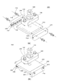
5, the
The
The
5, two
The supporting
The sliding
Since the Teflon bearing has a small frictional resistance, the Teflon bearing is provided inside the
The
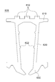
6, the
The
The
The fixing
Each of the fixing
The fixing
Two
The bearing
The
One end of the
The
More specifically, when the holding
Meanwhile, the other end of the
Although the
Various modified examples of the rigid electric wire and the connection structure thus installed will be described with reference to the drawings.
8 is a sectional view of a rigid electric wire according to the first embodiment of the present invention.
Referring to FIG. 8, the
In the present embodiment, the two
It is confirmed that the
Table 1 compares the experimental results of the stress and deformation amount (deflection amount) of the rigid body line according to the first embodiment of the present invention and the general rigid body line shown in Fig.
As shown in Table 1, it can be seen that the rigid electric wire according to the first embodiment of the present invention significantly improves the stress level and the deflection amount, thereby ensuring stability and reliability even when applied to a high-speed railway.
The clamping
The
Therefore, when the
Particularly, since the rigid
Further, the shape of the
When the inflection point is increased, the tension applied to the
In addition, although the thickness of the
9 is a sectional view of a rigid electric wire according to a second embodiment of the present invention.
9, the rigid
In the second embodiment, an
A plurality of the
The
Accordingly, not only stress and strain applied to the
The clamping
FIG. 10 is a cross-sectional view of a rigid-body electric wire according to a third embodiment of the present invention, and FIG. 11 is a cross-sectional view illustrating a rigid-wire connection structure according to a third embodiment of the present invention.
10 and 11, the
Meanwhile, in the present embodiment, at least one
The
11, a
The
At this time, the
The
A
The maximum thickness D1 of the
The length and thickness of the
12 is a cross-sectional view illustrating a rigid body connection structure according to a fourth embodiment of the present invention.
12, the
A
In the previous embodiment, two
As described above, the
Of course, ultimately, as in the previous embodiment, not only the accuracy and convenience of the alignment operation can be ensured, but also the secondary sectional area moment of the
The above-described rigid-body electric wire according to the present invention can secure a sufficient gripping force for a catenary, minimize stress and deformation applied to a rigid body line, and improve rigidity by improving rigidity.
In addition, it is possible to secure the safety and reliability of railway operation by the influence of pressure and lift from the pantograph as the speed of electric railway is increased. Also, by improving the sectional shape of the rigid catenary cable, structural stability can be achieved, have.
Also, it is possible to improve the productivity by aligning the connection part of the solid body line easily and precisely, and to prevent the deformation due to the self weight of the solid body line, it is possible to secure stability and reliability even when applied to the high speed railway. Sectional area can be sufficiently secured and the contact surface between the rigid body line and the connecting plate can be prevented from being reduced.
While the present invention has been particularly shown and described with reference to exemplary embodiments thereof, it will be apparent to those skilled in the art that various modifications and variations can be made in the present invention without departing from the spirit and scope of the invention as defined in the appended claims. You can do it. It is therefore to be understood that the modified embodiments are included in the technical scope of the present invention if they basically include elements of the claims of the present invention.
50: Rigid body line 100: Expansion joint
200: Support clamp 300: Support bracket
Claims (8)
Two tension arms integrally connected to the main bar and extending downward so as to be symmetrical to each other; And
And two clamping arms connected to the two tension arms and extending to face each other to a position spaced apart by a predetermined distance,
Wherein the two tension arms are formed such that the gap between the two tension arms is closer to the lower side.
Further comprising at least one upper protrusion provided on the main bar and increasing the rigidity so as to reduce the stress and deformation amount applied to the rigid body line.
Further comprising at least one protrusion protruding from the inside of the tension arm.
A first connection plate provided inside the tension arm;
A second connection plate provided outside the tension arm; And
And at least one protrusion protruding inward of the tension arm to align the first connection plate at a predetermined position.
Further comprising an insertion groove formed in the first connection plate to correspond to the protrusion.
Wherein the protrusions are protruded so as to form a soft curve in cross section, and the insertion grooves are formed to have a triangular section.
Wherein a maximum thickness D1 of the second connection plate is less than 1/2 of a distance D2 from an end of the main bar to a tension arm closest to the end of the main bar.
Wherein the two tension arms are formed to be inclined so that a gap between the two tension arms approaches each other.
Priority Applications (1)
| Application Number | Priority Date | Filing Date | Title |
|---|---|---|---|
| KR1020150162797A KR20170058766A (en) | 2015-11-19 | 2015-11-19 | double-tension rigid bar and connecting structure of the same |
Applications Claiming Priority (1)
| Application Number | Priority Date | Filing Date | Title |
|---|---|---|---|
| KR1020150162797A KR20170058766A (en) | 2015-11-19 | 2015-11-19 | double-tension rigid bar and connecting structure of the same |
Publications (1)
| Publication Number | Publication Date |
|---|---|
| KR20170058766A true KR20170058766A (en) | 2017-05-29 |
Family
ID=59053658
Family Applications (1)
| Application Number | Title | Priority Date | Filing Date |
|---|---|---|---|
| KR1020150162797A KR20170058766A (en) | 2015-11-19 | 2015-11-19 | double-tension rigid bar and connecting structure of the same |
Country Status (1)
| Country | Link |
|---|---|
| KR (1) | KR20170058766A (en) |
Cited By (3)
| Publication number | Priority date | Publication date | Assignee | Title |
|---|---|---|---|---|
| CN107985126A (en) * | 2017-12-26 | 2018-05-04 | 南京金城轨道交通设备有限公司 | A kind of conductive bus-bar |
| KR20190091912A (en) * | 2018-01-30 | 2019-08-07 | 엘에스전선 주식회사 | Rigid conductor and rigid conductor overlap |
| KR20190109844A (en) * | 2018-03-19 | 2019-09-27 | 엘에스전선 주식회사 | Vibration absorbing device and rigid bar transition device having the same |
-
2015
- 2015-11-19 KR KR1020150162797A patent/KR20170058766A/en active Search and Examination
Cited By (3)
| Publication number | Priority date | Publication date | Assignee | Title |
|---|---|---|---|---|
| CN107985126A (en) * | 2017-12-26 | 2018-05-04 | 南京金城轨道交通设备有限公司 | A kind of conductive bus-bar |
| KR20190091912A (en) * | 2018-01-30 | 2019-08-07 | 엘에스전선 주식회사 | Rigid conductor and rigid conductor overlap |
| KR20190109844A (en) * | 2018-03-19 | 2019-09-27 | 엘에스전선 주식회사 | Vibration absorbing device and rigid bar transition device having the same |
Similar Documents
| Publication | Publication Date | Title |
|---|---|---|
| CN102481861B (en) | For the cantilever of the live electric cable of support iron route, contact line and subway line | |
| KR101746285B1 (en) | support clamp for conductor rail | |
| EP3260326B1 (en) | Temperature compensation device for rigid overhead catenary | |
| KR101910230B1 (en) | connecting structure of rigid bar | |
| US20190118672A1 (en) | A power rail expansion joint without expansion gap | |
| KR20140110324A (en) | support clamp and rigid bar support system including the same | |
| KR200497341Y1 (en) | Support Clamp For Conductor Rail | |
| KR20170058766A (en) | double-tension rigid bar and connecting structure of the same | |
| KR101494996B1 (en) | Expansion connection arrangement for adjoining power rails of an overhead line system for electric locomotives | |
| KR20170043437A (en) | expansion joint | |
| KR101925149B1 (en) | expansion joint | |
| KR101900512B1 (en) | rigid bar support system | |
| KR101902361B1 (en) | Section insulator for rigid trolley line | |
| CN110509820A (en) | For connecting the attachment device of conductor rail and with its conductive rail assembly | |
| CN104627027A (en) | DC (direct current) 750V-3 kV flexible hanging section insulator | |
| KR20170039432A (en) | rigid bar | |
| US4187934A (en) | Section insulator for catenary systems | |
| CN102427172B (en) | Telescopic connector used for supporting power supply rail | |
| KR20170045849A (en) | reversely inclined rigid bar | |
| DK2613962T3 (en) | Stretch separation device for a busbar conduit system | |
| CN104538812A (en) | Slide wire installed on light rail | |
| KR102602939B1 (en) | Rigid conductor and rigid conductor overlap | |
| CN214899225U (en) | High-voltage feed system of railway side-moving type rigid contact net | |
| CN201712490U (en) | Tunnel partial tension compensation contact line system | |
| KR100933500B1 (en) | Fixing type insulation for an over head line |
Legal Events
| Date | Code | Title | Description |
|---|---|---|---|
| A201 | Request for examination | ||
| A302 | Request for accelerated examination | ||
| E902 | Notification of reason for refusal | ||
| AMND | Amendment | ||
| AMND | Amendment | ||
| E902 | Notification of reason for refusal | ||
| AMND | Amendment |