KR20170048954A - laser cladding system and method of using the same - Google Patents
laser cladding system and method of using the same Download PDFInfo
- Publication number
- KR20170048954A KR20170048954A KR1020150149686A KR20150149686A KR20170048954A KR 20170048954 A KR20170048954 A KR 20170048954A KR 1020150149686 A KR1020150149686 A KR 1020150149686A KR 20150149686 A KR20150149686 A KR 20150149686A KR 20170048954 A KR20170048954 A KR 20170048954A
- Authority
- KR
- South Korea
- Prior art keywords
- cladding
- laser
- cladding layer
- workpiece
- base plate
- Prior art date
Links
- 238000004372 laser cladding Methods 0.000 title claims abstract description 47
- 238000000034 method Methods 0.000 title claims abstract description 28
- 238000005253 cladding Methods 0.000 claims abstract description 82
- 239000000463 material Substances 0.000 claims abstract description 26
- 238000012545 processing Methods 0.000 claims abstract description 22
- 239000000843 powder Substances 0.000 claims description 15
- 238000003754 machining Methods 0.000 claims description 4
- 230000015572 biosynthetic process Effects 0.000 claims description 3
- 238000002844 melting Methods 0.000 claims description 3
- 230000008018 melting Effects 0.000 claims description 3
- 229910052751 metal Inorganic materials 0.000 description 7
- 239000002184 metal Substances 0.000 description 7
- 238000005516 engineering process Methods 0.000 description 5
- 238000004519 manufacturing process Methods 0.000 description 4
- 239000000919 ceramic Substances 0.000 description 3
- 229910045601 alloy Inorganic materials 0.000 description 2
- 239000000956 alloy Substances 0.000 description 2
- 238000002591 computed tomography Methods 0.000 description 2
- 238000002595 magnetic resonance imaging Methods 0.000 description 2
- 150000002739 metals Chemical class 0.000 description 2
- 238000000465 moulding Methods 0.000 description 2
- 239000000123 paper Substances 0.000 description 2
- 238000009825 accumulation Methods 0.000 description 1
- 238000005266 casting Methods 0.000 description 1
- 238000005520 cutting process Methods 0.000 description 1
- 238000010586 diagram Methods 0.000 description 1
- 230000000694 effects Effects 0.000 description 1
- 230000001678 irradiating effect Effects 0.000 description 1
- 239000000155 melt Substances 0.000 description 1
- 238000012986 modification Methods 0.000 description 1
- 230000004048 modification Effects 0.000 description 1
- 238000012544 monitoring process Methods 0.000 description 1
- 229920003023 plastic Polymers 0.000 description 1
- 239000004033 plastic Substances 0.000 description 1
- 238000007634 remodeling Methods 0.000 description 1
- 239000004065 semiconductor Substances 0.000 description 1
- 239000000758 substrate Substances 0.000 description 1
- 238000012546 transfer Methods 0.000 description 1
Images


Classifications
-
- B29C67/0085—
-
- B—PERFORMING OPERATIONS; TRANSPORTING
- B22—CASTING; POWDER METALLURGY
- B22F—WORKING METALLIC POWDER; MANUFACTURE OF ARTICLES FROM METALLIC POWDER; MAKING METALLIC POWDER; APPARATUS OR DEVICES SPECIALLY ADAPTED FOR METALLIC POWDER
- B22F3/00—Manufacture of workpieces or articles from metallic powder characterised by the manner of compacting or sintering; Apparatus specially adapted therefor ; Presses and furnaces
- B22F3/10—Sintering only
- B22F3/105—Sintering only by using electric current other than for infrared radiant energy, laser radiation or plasma ; by ultrasonic bonding
-
- B—PERFORMING OPERATIONS; TRANSPORTING
- B23—MACHINE TOOLS; METAL-WORKING NOT OTHERWISE PROVIDED FOR
- B23C—MILLING
- B23C3/00—Milling particular work; Special milling operations; Machines therefor
- B23C3/12—Trimming or finishing edges, e.g. deburring welded corners
-
- B—PERFORMING OPERATIONS; TRANSPORTING
- B23—MACHINE TOOLS; METAL-WORKING NOT OTHERWISE PROVIDED FOR
- B23C—MILLING
- B23C5/00—Milling-cutters
- B23C5/02—Milling-cutters characterised by the shape of the cutter
- B23C5/10—Shank-type cutters, i.e. with an integral shaft
-
- B—PERFORMING OPERATIONS; TRANSPORTING
- B23—MACHINE TOOLS; METAL-WORKING NOT OTHERWISE PROVIDED FOR
- B23K—SOLDERING OR UNSOLDERING; WELDING; CLADDING OR PLATING BY SOLDERING OR WELDING; CUTTING BY APPLYING HEAT LOCALLY, e.g. FLAME CUTTING; WORKING BY LASER BEAM
- B23K26/00—Working by laser beam, e.g. welding, cutting or boring
- B23K26/34—Laser welding for purposes other than joining
- B23K26/342—Build-up welding
-
- B29C67/0088—
-
- B—PERFORMING OPERATIONS; TRANSPORTING
- B33—ADDITIVE MANUFACTURING TECHNOLOGY
- B33Y—ADDITIVE MANUFACTURING, i.e. MANUFACTURING OF THREE-DIMENSIONAL [3-D] OBJECTS BY ADDITIVE DEPOSITION, ADDITIVE AGGLOMERATION OR ADDITIVE LAYERING, e.g. BY 3-D PRINTING, STEREOLITHOGRAPHY OR SELECTIVE LASER SINTERING
- B33Y30/00—Apparatus for additive manufacturing; Details thereof or accessories therefor
-
- B—PERFORMING OPERATIONS; TRANSPORTING
- B33—ADDITIVE MANUFACTURING TECHNOLOGY
- B33Y—ADDITIVE MANUFACTURING, i.e. MANUFACTURING OF THREE-DIMENSIONAL [3-D] OBJECTS BY ADDITIVE DEPOSITION, ADDITIVE AGGLOMERATION OR ADDITIVE LAYERING, e.g. BY 3-D PRINTING, STEREOLITHOGRAPHY OR SELECTIVE LASER SINTERING
- B33Y40/00—Auxiliary operations or equipment, e.g. for material handling
-
- B—PERFORMING OPERATIONS; TRANSPORTING
- B33—ADDITIVE MANUFACTURING TECHNOLOGY
- B33Y—ADDITIVE MANUFACTURING, i.e. MANUFACTURING OF THREE-DIMENSIONAL [3-D] OBJECTS BY ADDITIVE DEPOSITION, ADDITIVE AGGLOMERATION OR ADDITIVE LAYERING, e.g. BY 3-D PRINTING, STEREOLITHOGRAPHY OR SELECTIVE LASER SINTERING
- B33Y50/00—Data acquisition or data processing for additive manufacturing
- B33Y50/02—Data acquisition or data processing for additive manufacturing for controlling or regulating additive manufacturing processes
Landscapes
- Engineering & Computer Science (AREA)
- Manufacturing & Machinery (AREA)
- Mechanical Engineering (AREA)
- Physics & Mathematics (AREA)
- Optics & Photonics (AREA)
- Chemical & Material Sciences (AREA)
- Materials Engineering (AREA)
- Plasma & Fusion (AREA)
- Laser Beam Processing (AREA)
Abstract
The present invention relates to a laser cladding system and a laser cladding method using the same. The laser cladding system includes a base plate on which a material is placed at a predetermined position, first and second moving frames spaced apart from each other on the base plate, And a cladding layer provided on one side of the cladding means and measuring the thickness of the cladding layer. The cladding layer is provided on the second moving frame, And a processing means for processing the microscopic burrs present on the surface into an end mill. The present invention also provides a laser cladding system and a laser cladding method using the laser cladding system.
Description
The present invention relates to a laser cladding system and a laser cladding method using the laser cladding system. More specifically, the present invention relates to a laser cladding system for improving vulnerability generated on various machine parts and materials, surface processing by a simple process, And a laser cladding method using the same.
Laser-aided direct metal manufacturing is a process that uses precision materials such as metals, alloys, ceramics, etc., The laser cladding technique can be used to produce the tools necessary for producing a three-dimensional product or a product in a very short time.
The three-dimensional shape information includes three-dimensional CAD data, medical CT (computer tomography) and MRI (Magnetic Resonance Imaging) data, and digital data measured by a 3D object digitizing system It says.
A tool is a mass-production mold necessary for producing a die or a mold.
These technologies can be used to produce metal prototypes, mass production molds, complex final products and tools in a short period of time comparable to conventional machining methods such as cutting and casting using CNC (Computerized Numerical Control) And can also be applied to restoration, remodeling and repairing of a mold using reverse engineering.
The basic concept of implementing the physical shape from CAD data is similar to a general printer. Just as a printer produces documents by inking ink at precise locations on a two-dimensional paper plane using document data files stored on a computer, the direct molding technique uses three-dimensional CAD data to accurately position the three- Dimensional physical shape by forming a desired amount of functional material. These technologies are being developed as 3D printers and have recently been used in different directions depending on the characteristics of materials such as plastics, ceramics, paper, and metals.
In a laser direct metal forming technology, a two-dimensional plane is implemented physically using laser cladding technology.
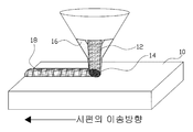
1 is a view for explaining a general laser cladding process.
The laser cladding is formed by locally forming a
In the laser direct metal forming technology, two-dimensional cross-sectional information is calculated from three-dimensional CAD data, and a cladding layer having a shape, thickness and / or height corresponding to each two-dimensional cross-sectional information is sequentially formed, It makes products or tools quickly.
The shape of the cladding layer corresponding to the two-dimensional cross-sectional information in the molding process depends mainly on the accuracy of the tool path and the transfer system calculated from the cross-sectional information, and the physical implementation is relatively easy. However, the height of the laser cladding layer depends on the output of the laser, the mode of the laser beam, the size of the laser beam, the feed rate of the material, the characteristics of the cladding powder, the powder feed rate, the falling rate of the powder, The type and the flow rate of the gas. External factors such as the temperature change of the material surface caused by heat accumulation during the cladding process, the material surface and the state of the laser oscillator also affect the height of the cladding layer formed.
Therefore, in order to obtain the height of the cladding layer corresponding to the two-dimensional cross-sectional information, there is a technical difficulty to control the process parameters affecting the height of the cladding layer in real time by monitoring the formation process of the cladding layer in real time.
In the conventional laser cladding process, it is difficult to accurately form a cladding layer due to an error occurring when the cladding layers are stacked due to plasma generated during the operation, There is a problem that it is difficult to utilize the laser cladding system in the work.
SUMMARY OF THE INVENTION Accordingly, the present invention has been made in an effort to solve the above-mentioned problems, and it is an object of the present invention to provide a cladding layer that can be formed by precisely controlling the thickness of a cladding layer formed on a work, And a laser cladding method using the same.
In order to achieve the above and other objects of the present invention, according to an embodiment of the present invention, there is provided a method of manufacturing a semiconductor device, comprising: a base plate on which a material is placed at a predetermined position; first and second movable frames spaced apart from each other on the base plate; A cladding layer provided on the first moving frame to form a cladding layer on the surface of the workpiece; measuring means provided on one side of the cladding means for measuring a thickness of the cladding layer; And processing means for processing a microscopic burr present on the surface of the cladding layer into an end mill.
The cladding means includes a cylinder coupled to a rail provided on an upper lower surface of the first moving frame and a support plate coupled to an end of a cylinder rod provided in the cylinder to irradiate a rare- And a cladding material supply member provided on the support plate at a predetermined distance from the laser head to supply cladding powder and auxiliary gas to the surface of the workpiece at the same time.
And the measuring means is any one of a 3D scanning or a CCD camera.
And an automatic tool changer (ATC) is installed at a predetermined position on one side of the base plate to automatically replace the end mill provided in the machining means.
It is still another object of the present invention to provide a laser cladding method using a laser cladding system, comprising the steps of: placing a material at a predetermined position of the base plate; cladding a surface of the material using cladding means provided on the first moving frame; Forming a cladding layer by melting the surface of the workpiece and the cladding powder by oscillating the laser beam while supplying the powder and the auxiliary gas at the same time; measuring the thickness of the cladding layer using the measuring means; A step of processing the surface of the cladding layer by the processing means so as to remove a minute burr present on a surface of the cladding layer formed on the surface of the cladding layer, And repeating the processing step.
According to the present invention having the above-mentioned constitution, the effect of enabling the formation of the cladding layer formed on the material by precisely controlling the thickness of the cladding layer formed on the surface of the cladding layer, irrespective of the moving direction of the laser beam or the material have.
1 is a view for explaining a conventional laser cladding process;
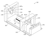
2 is a schematic view showing a laser cladding system according to an embodiment of the present invention;
3 is a side view of the laser cladding means shown in Fig.
4 is a side view of the processing means shown in Fig.
5A and 5B are operational states of a laser cladding system according to an embodiment of the present invention.
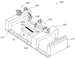
FIG. 6 is a schematic view showing a laser cladding system according to a modified embodiment of the present invention; FIG.
Hereinafter, preferred embodiments of the present invention will be described in detail with reference to the accompanying drawings. In this process, the thicknesses of the lines and the sizes of the components shown in the drawings may be exaggerated for clarity and convenience of explanation.
In addition, the terms described below are defined in consideration of the functions of the present invention, which may vary depending on the intention or custom of the user, the operator. Therefore, definitions of these terms should be made based on the contents throughout this specification.
FIG. 3 is a side view of the cladding means shown in FIG. 2; FIG. 4 is a side view of the processing means shown in FIG. 2; And FIG. 5B is an operational state diagram of a laser cladding system according to an embodiment of the present invention.
2 to 5B, a
The
The first and second moving
The laser cladding means 140 is provided on the first moving
That is, while the cladding powder and the auxiliary gas are simultaneously supplied from the cladding
The
The
The machining means 160 is provided on the second moving
When the height of the cladding layer is different from the input value (lower or higher), the cladding layer is processed by an end mill so that the height of the cladding layers is the same as the input value.
At this time, the processing means 160 includes a
An automatic tool changer (not shown) is provided at a predetermined position on one side of the
FIG. 6 is a schematic view showing a laser cladding system according to a modified embodiment of the present invention.
Referring to FIG. 6, a laser cladding system according to an exemplary embodiment of the present invention is similar to the laser cladding system of the present invention, except that the first and
The laser cladding method using the laser cladding system as described above includes the steps of placing the
More specifically, after a cladding layer is formed on the surface of the
Although the preferred embodiments of the present invention have been described with reference to the accompanying drawings, it will be apparent to those skilled in the art that various modifications and variations can be made in the present invention without departing from the spirit of the invention It can be understood that it is possible.
110; Base plate
120; The first movable frame
122; rail
130; The second moving frame
132; rail
140; Laser cladding means
142; cylinder
142a; Cylinder rod
144; Support plate
146; Laser head
148; Cladding material supply member
150; Measuring means
160; Processing means
162; cylinder
162a; Cylinder rod
164; Support plate
166; main body
168; End mill
170; Automatic tool changing means
Claims (5)
First and second moving frames spaced apart from each other on the base plate;
Laser cladding means provided on the first moving frame to form a cladding layer on a surface of the workpiece;
Measuring means installed on one side of the cladding means for measuring a thickness of the cladding layer; And
And a processing unit that is installed in the second moving frame and processes a microscopic burr present on a surface of the cladding layer into an end mill.
A cylinder coupled to a rail provided on an upper lower side of the first moving frame; a laser head mounted on a support plate coupled to an end of a cylinder rod provided in the cylinder, the laser head oscillating a laser beam on a surface of the work; And a cladding material supply member installed on the support plate at a predetermined distance from the laser head to simultaneously supply the cladding powder and the auxiliary gas to the surface of the workpiece.
Wherein the measuring means is one of a 3D scanning or a CCD camera.
Wherein an automatic tool changer (ATC) is installed at a predetermined position on one side of the base plate to automatically replace the end mill provided in the machining means.
Placing a material on a predetermined position of the base plate;
Forming a cladding layer by melting a surface of a workpiece and a cladding powder while supplying a cladding powder and an auxiliary gas to the surface of the workpiece simultaneously using laser cladding means provided in the first moving frame;
Measuring the thickness of the cladding layer using the measuring means;
Processing the surface of the cladding layer with the processing means to remove a minute burr present on the surface of the cladding layer formed on the surface of the workpiece; And
And repeating the cladding layer forming step and the processing step until the cladding formation of the workpiece is completed.
Priority Applications (1)
| Application Number | Priority Date | Filing Date | Title |
|---|---|---|---|
| KR1020150149686A KR20170048954A (en) | 2015-10-27 | 2015-10-27 | laser cladding system and method of using the same |
Applications Claiming Priority (1)
| Application Number | Priority Date | Filing Date | Title |
|---|---|---|---|
| KR1020150149686A KR20170048954A (en) | 2015-10-27 | 2015-10-27 | laser cladding system and method of using the same |
Publications (1)
| Publication Number | Publication Date |
|---|---|
| KR20170048954A true KR20170048954A (en) | 2017-05-10 |
Family
ID=58743882
Family Applications (1)
| Application Number | Title | Priority Date | Filing Date |
|---|---|---|---|
| KR1020150149686A KR20170048954A (en) | 2015-10-27 | 2015-10-27 | laser cladding system and method of using the same |
Country Status (1)
| Country | Link |
|---|---|
| KR (1) | KR20170048954A (en) |
Cited By (6)
| Publication number | Priority date | Publication date | Assignee | Title |
|---|---|---|---|---|
| CN107686989A (en) * | 2017-07-21 | 2018-02-13 | 浙江工业大学 | A kind of electromagnetic field regulation device for laser manufacture |
| CN109590678A (en) * | 2018-11-12 | 2019-04-09 | 中国航天空气动力技术研究院 | The production method and equipment of 3D printing composite space pressure vessel metal inner lining |
| CN110682099A (en) * | 2019-10-10 | 2020-01-14 | 河北瑞兆激光再制造技术股份有限公司 | Axle prosthetic devices under complicated stress condition |
| KR20220168078A (en) * | 2021-06-15 | 2022-12-22 | 주식회사 코렌텍 | Deviation Tolerance Correction Method for Using Additive Manufacturing |
| KR102507407B1 (en) * | 2022-12-09 | 2023-03-08 | 터보파워텍(주) | Fixture for thermal barrier coating of hot gas path parts by 3D printing laser cladding |
| CN116728001A (en) * | 2023-08-16 | 2023-09-12 | 西南交通大学 | High-integrity metal material surface processing method with gradient refinement of crystal grains |
-
2015
- 2015-10-27 KR KR1020150149686A patent/KR20170048954A/en not_active Application Discontinuation
Cited By (8)
| Publication number | Priority date | Publication date | Assignee | Title |
|---|---|---|---|---|
| CN107686989A (en) * | 2017-07-21 | 2018-02-13 | 浙江工业大学 | A kind of electromagnetic field regulation device for laser manufacture |
| CN109590678A (en) * | 2018-11-12 | 2019-04-09 | 中国航天空气动力技术研究院 | The production method and equipment of 3D printing composite space pressure vessel metal inner lining |
| CN110682099A (en) * | 2019-10-10 | 2020-01-14 | 河北瑞兆激光再制造技术股份有限公司 | Axle prosthetic devices under complicated stress condition |
| KR20220168078A (en) * | 2021-06-15 | 2022-12-22 | 주식회사 코렌텍 | Deviation Tolerance Correction Method for Using Additive Manufacturing |
| WO2022265327A1 (en) * | 2021-06-15 | 2022-12-22 | 주식회사 코렌텍 | Tolerance deviation correction method using lamination |
| KR102507407B1 (en) * | 2022-12-09 | 2023-03-08 | 터보파워텍(주) | Fixture for thermal barrier coating of hot gas path parts by 3D printing laser cladding |
| CN116728001A (en) * | 2023-08-16 | 2023-09-12 | 西南交通大学 | High-integrity metal material surface processing method with gradient refinement of crystal grains |
| CN116728001B (en) * | 2023-08-16 | 2023-11-03 | 西南交通大学 | High-integrity metal material surface processing method with gradient refinement of crystal grains |
Similar Documents
| Publication | Publication Date | Title |
|---|---|---|
| US11104064B2 (en) | Method and arrangement for producing a workpiece by using additive manufacturing techniques | |
| KR20170048954A (en) | laser cladding system and method of using the same | |
| US10688581B2 (en) | 3D metal printing device and process | |
| CN105945281B (en) | The deposition forming machining manufacture of part and mold | |
| US11975481B2 (en) | Adaptive closed-loop control of additive manufacturing for producing a workpiece | |
| JP6943512B2 (en) | Equipment and methods for construction surface mapping | |
| US10994355B2 (en) | Metal laminating and molding method | |
| CN112236289B (en) | Method and system for automatic tool path generation | |
| KR101790154B1 (en) | Laser cladding method and system | |
| CN105039971A (en) | Laser 3D printer and method for mold remanufacturing | |
| JP2018531815A (en) | Improving the control of, or related to, chain control of machines, including additive manufacturing machines, in the manufacture of workpieces. | |
| KR101492339B1 (en) | Method for controlling laser cladding and laser cladding system | |
| KR101673062B1 (en) | Method for measuring height of melt pool generated in laser cladding | |
| CN106032064B (en) | A kind of 3D printing aftertreatment technology based on FDM technology | |
| KR101692141B1 (en) | Forming device for three-dimensional structure and forming method thereof | |
| CA2913288C (en) | 3d metal printing device and process | |
| Tuteski et al. | Mold Design and Production by Using Additive Manufacturing (AM)–Present Status and Future Perspectives | |
| Wagiman et al. | Effect of GMAW-CMT heat input on weld bead profile geometry for freeform fabrication of aluminium parts | |
| DeWitte et al. | Initial process planning of a hybrid multi-tasking platform | |
| Chougule et al. | Design & manufacturing of components of modified bench vise on rapid prototype machine | |
| KR20160126949A (en) | Method for creating work path of work piece using laser cladding system | |
| JP6250355B2 (en) | Modeling equipment | |
| CN107617859A (en) | A kind of Digit Control Machine Tool aftertreatment technology based on SLS3D print dies | |
| Khan et al. | Development of novel hybrid manufacturing technique for manufacturing support structures free complex parts | |
| CN204939614U (en) | Mould manufactures laser 3D printer again |
Legal Events
| Date | Code | Title | Description |
|---|---|---|---|
| A201 | Request for examination | ||
| E902 | Notification of reason for refusal | ||
| E601 | Decision to refuse application |