KR20170045564A - Battery Cell Comprising Inner Surface Coated with Electrical Insulating Material - Google Patents
Battery Cell Comprising Inner Surface Coated with Electrical Insulating Material Download PDFInfo
- Publication number
- KR20170045564A KR20170045564A KR1020150145280A KR20150145280A KR20170045564A KR 20170045564 A KR20170045564 A KR 20170045564A KR 1020150145280 A KR1020150145280 A KR 1020150145280A KR 20150145280 A KR20150145280 A KR 20150145280A KR 20170045564 A KR20170045564 A KR 20170045564A
- Authority
- KR
- South Korea
- Prior art keywords
- battery case
- battery
- cell according
- battery cell
- insulating material
- Prior art date
Links
Images


Classifications
-
- H01M2/0267—
-
- H—ELECTRICITY
- H01—ELECTRIC ELEMENTS
- H01M—PROCESSES OR MEANS, e.g. BATTERIES, FOR THE DIRECT CONVERSION OF CHEMICAL ENERGY INTO ELECTRICAL ENERGY
- H01M10/00—Secondary cells; Manufacture thereof
- H01M10/05—Accumulators with non-aqueous electrolyte
- H01M10/052—Li-accumulators
-
- H—ELECTRICITY
- H01—ELECTRIC ELEMENTS
- H01M—PROCESSES OR MEANS, e.g. BATTERIES, FOR THE DIRECT CONVERSION OF CHEMICAL ENERGY INTO ELECTRICAL ENERGY
- H01M10/00—Secondary cells; Manufacture thereof
- H01M10/05—Accumulators with non-aqueous electrolyte
- H01M10/058—Construction or manufacture
-
- H01M2/0272—
-
- H01M2/0287—
-
- H01M2/1016—
-
- H—ELECTRICITY
- H01—ELECTRIC ELEMENTS
- H01M—PROCESSES OR MEANS, e.g. BATTERIES, FOR THE DIRECT CONVERSION OF CHEMICAL ENERGY INTO ELECTRICAL ENERGY
- H01M2220/00—Batteries for particular applications
- H01M2220/10—Batteries in stationary systems, e.g. emergency power source in plant
-
- H—ELECTRICITY
- H01—ELECTRIC ELEMENTS
- H01M—PROCESSES OR MEANS, e.g. BATTERIES, FOR THE DIRECT CONVERSION OF CHEMICAL ENERGY INTO ELECTRICAL ENERGY
- H01M2220/00—Batteries for particular applications
- H01M2220/20—Batteries in motive systems, e.g. vehicle, ship, plane
-
- H—ELECTRICITY
- H01—ELECTRIC ELEMENTS
- H01M—PROCESSES OR MEANS, e.g. BATTERIES, FOR THE DIRECT CONVERSION OF CHEMICAL ENERGY INTO ELECTRICAL ENERGY
- H01M2220/00—Batteries for particular applications
- H01M2220/30—Batteries in portable systems, e.g. mobile phone, laptop
-
- Y—GENERAL TAGGING OF NEW TECHNOLOGICAL DEVELOPMENTS; GENERAL TAGGING OF CROSS-SECTIONAL TECHNOLOGIES SPANNING OVER SEVERAL SECTIONS OF THE IPC; TECHNICAL SUBJECTS COVERED BY FORMER USPC CROSS-REFERENCE ART COLLECTIONS [XRACs] AND DIGESTS
- Y02—TECHNOLOGIES OR APPLICATIONS FOR MITIGATION OR ADAPTATION AGAINST CLIMATE CHANGE
- Y02E—REDUCTION OF GREENHOUSE GAS [GHG] EMISSIONS, RELATED TO ENERGY GENERATION, TRANSMISSION OR DISTRIBUTION
- Y02E60/00—Enabling technologies; Technologies with a potential or indirect contribution to GHG emissions mitigation
- Y02E60/10—Energy storage using batteries
-
- Y02E60/122—
-
- Y—GENERAL TAGGING OF NEW TECHNOLOGICAL DEVELOPMENTS; GENERAL TAGGING OF CROSS-SECTIONAL TECHNOLOGIES SPANNING OVER SEVERAL SECTIONS OF THE IPC; TECHNICAL SUBJECTS COVERED BY FORMER USPC CROSS-REFERENCE ART COLLECTIONS [XRACs] AND DIGESTS
- Y02—TECHNOLOGIES OR APPLICATIONS FOR MITIGATION OR ADAPTATION AGAINST CLIMATE CHANGE
- Y02P—CLIMATE CHANGE MITIGATION TECHNOLOGIES IN THE PRODUCTION OR PROCESSING OF GOODS
- Y02P70/00—Climate change mitigation technologies in the production process for final industrial or consumer products
- Y02P70/50—Manufacturing or production processes characterised by the final manufactured product
Abstract
Description
본 발명은 전지케이스의 내면이 전기 절연성 소재로 코팅되어 있는 전지셀에 관한 것이다.The present invention relates to a battery cell in which an inner surface of a battery case is coated with an electrically insulating material.
최근, 화석연료의 고갈에 의한 에너지원의 가격 상승, 환경 오염의 관심이 증폭되며, 친환경 대체 에너지원에 대한 요구가 미래생활을 위한 필수 불가결한 요인이 되고 있다. 이에 원자력, 태양광, 풍력, 조력 등 다양한 전력 생산기술들에 대한 연구가 지속되고 있으며, 이렇게 생산된 에너지를 더욱 효율적으로 사용하기 위한 전력저장장치 또한 지대한 관심이 이어지고 있다.In recent years, the demand for environmentally friendly alternative energy sources has become an indispensable factor for the future, as the increase in the price of energy sources due to depletion of fossil fuels and the interest in environmental pollution are amplified. Various researches on power generation technologies such as nuclear power, solar power, wind power, and tidal power have been continuing, and electric power storage devices for more efficient use of such generated energy have also been attracting much attention.
특히, 모바일 기기에 대한 기술 개발과 수요가 증가함에 따라 에너지원으로서의 전지의 수요가 급격히 증가하고 있고, 그에 따라 다양한 요구에 부응할 수 있는 전지에 대한 많은 연구가 행해지고 있다.Particularly, as technology development and demand for mobile devices are increasing, the demand for batteries as energy sources is rapidly increasing, and accordingly, a lot of researches on batteries that can meet various demands have been conducted.
대표적으로 전지의 형상 면에서는 얇은 두께로 휴대폰 등과 같은 제품들에 적용될 수 있는 각형 이차전지와 파우치형 이차전지에 대한 수요가 높고, 재료 면에서는 높은 에너지 밀도, 방전 전압, 출력 안정성 등의 장점을 가진 리튬이온 전지, 리튬이온 폴리머 전지 등과 같은 리튬 이차전지에 대한 수요가 높다.Typically, in terms of the shape of a battery, there is a high demand for a prismatic secondary battery and a pouch-type secondary battery which can be applied to products such as mobile phones with a small thickness, and has advantages such as high energy density, discharge voltage, There is a high demand for lithium secondary batteries such as lithium ion batteries and lithium ion polymer batteries.
또한, 이차전지는 양극, 음극, 및 양극과 음극 사이에 개재되는 분리막이 적층된 구조의 전극조립체가 어떠한 구조로 이루어져 있는지에 따라 분류되기도 하는 바, 대표적으로는, 긴 시트형의 양극들과 음극들을 분리막이 개재된 상태에서 권취한 구조의 젤리-롤형(권취형) 전극조립체, 소정 크기의 단위로 절취한 다수의 양극과 음극들을 분리막을 개재한 상태로 순차적으로 적층한 스택형(적층형) 전극조립체 등을 들 수 있으며, 최근에는, 상기 젤리-롤형 전극조립체 및 스택형 전극조립체가 갖는 문제점을 해결하기 위해, 상기 젤리-롤형과 스택형의 혼합 형태인 진일보한 구조의 전극조립체로서, 소정 단위의 양극과 음극들을 분리막을 개재한 상태로 적층한 단위셀들을 분리필름 상에 위치시킨 상태에서 순차적으로 권취한 구조의 스택/폴딩형 전극조립체가 개발되었다.Also, the secondary battery is classified according to the structure of the electrode assembly having the positive electrode, the negative electrode, and the separator interposed between the positive electrode and the negative electrode. Typically, the long battery- A stacked (stacked) electrode assembly in which a plurality of positive electrodes and negative electrodes cut in a predetermined size unit are sequentially stacked with a separator interposed therebetween, the jelly-roll type (wound type) electrode assembly having a structure in which a separator is interposed; In recent years, in order to solve the problems of the jelly-roll type electrode assembly and the stack type electrode assembly, an electrode assembly having an advanced structure, which is a combination of the jelly-roll type and the stack type, A stack / folding type electrode having a structure in which unit cells stacked with a separator interposed between an anode and a cathode are sequentially wound while being placed on a separation film Developed body lip.
또한, 이차전지는 전지케이스의 형상에 따라, 전극조립체가 원통형 또는 각형의 금속 캔에 내장되어 있는 원통형 전지 및 각형 전지와, 전극조립체가 알루미늄 라미네이트 시트의 파우치형 케이스에 내장되어 있는 파우치형 전지로 분류된다.The secondary battery includes a cylindrical battery and a prismatic battery in which the electrode assembly is housed in a cylindrical or rectangular metal can according to the shape of the battery case, and a pouch type battery in which the electrode assembly is housed in a pouch-shaped case of an aluminum laminate sheet .
특히, 최근에는 스택형 또는 스택/폴딩형 전극조립체를 알루미늄 라미네이트 시트의 파우치형 전지케이스에 내장한 구조의 파우치형 전지가, 낮은 제조비, 작은 중량, 용이한 형태 변형 등을 이유로, 많은 관심을 모으고 있고 또한 그것의 사용량이 점차적으로 증가하고 있다.In particular, in recent years, a pouch-shaped battery having a structure in which a stacked or stacked / folded electrode assembly is embedded in a pouch-shaped battery case of an aluminum laminate sheet has attracted much attention due to low manufacturing cost, small weight, And its usage is gradually increasing.
도 1에는 종래의 파우치형 전지셀의 구조를 개략적으로 나타낸 분해 사시도가 도시되어 있다.1 is an exploded perspective view schematically showing a structure of a conventional pouch-shaped battery cell.
도 1을 참조하면, 파우치형 전지셀(100)은, 전극조립체(130), 전극조립체(130)로부터 연장되어 있는 전극 탭들(131, 132), 전극 탭들(131, 132)에 용접되어 있는 전극리드들(140, 141), 및 전극조립체(130)를 수용하는 전지케이스(120)를 포함하는 것으로 구성되어 있다.1, the pouch-
전극조립체(130)는 분리막이 개재된 상태에서 양극과 음극이 순차적으로 적층되어 있는 발전소자로서, 스택형 또는 스택/폴딩형 구조로 이루어져 있다. 전극 탭들(131, 132)은 전극조립체(130)의 각 극판으로부터 연장되어 있고, 전극리드들(140, 141)은 각 극판으로부터 연장된 복수 개의 전극 탭들(131, 132)과, 예를 들어, 용접에 의해 각각 전기적으로 연결되어 있으며, 전지케이스(120)의 외부로 일부가 노출되어 있다. 또한, 전극리드들(140, 141)의 상하면 일부에는 전지케이스(120)와의 밀봉도를 높이고 동시에 전기적 절연상태를 확보하기 위하여 절연필름(150)이 부착되어 있다.The
전지케이스(120)는 전극조립체(130)가 안착될 수 있는 오목한 형상의 수납부(123)를 포함하는 케이스 본체(122)와 그러한 본체(122)에 일체로 연결되어 있는 덮개(121)로 이루어져 있고, 수납부(123)에 전극조립체(130)을 수납한 상태로 접촉부위인 양측부(124)와 상단부(125)를 결합시킴으로써 전지를 완성한다. 전지케이스(120)는 수지 외층/차단성의 금속층/열용융성 수지 실란트층의 알루미늄 라미네이트 구조로 이루어져 있어서, 서로 접하는 덮개(121)와 본체(122)의 양측부(124) 및 상단부(125) 부위에 열과 압력을 가하여 수지층을 상호 융착시킴으로써 결합시킨 밀봉 잉여부를 형성한다. 양측부(124)는 상하 전지케이스(120)의 동일한 수지층들이 직접 접하므로 용융에 의해 균일한 밀봉이 가능하다. 반면에, 상단부(125)에는 전극리드들(140, 141)이 돌출되어 있으므로 전극리드들(140, 141)의 두께 및 전지케이스(120) 소재와의 이질성을 고려하여 밀봉성을 높일 수 있도록 전극리드들(140, 141)과의 사이에 절연필름(150)을 개재한 상태에서 열융착시킨다.The
일반적으로, 이러한 구조의 파우치형 전지셀은 전지케이스에 대한 전극조립체와 전해액의 수납 공정, 열융착에 의한 전지케이스의 밀봉 공정, 충방전을 통한 숙성(aging) 공정, 숙성 공정에서 발생한 가스를 제거하기 위한 탈기(degas) 공정 등 다양한 공정을 거쳐 제조된다.Generally, the pouch-shaped battery cell having such a structure can be manufactured by a process of storing an electrode assembly and an electrolyte solution in a battery case, a sealing process of a battery case by heat fusion, an aging process by charging and discharging, And a degassing process for forming the film.
이때, 상기 각각의 공정들은 파우치형 전지셀을 소정의 진공 흡착에 의해 지그(jig) 내지 툴(tool)에 고정시킨 상태에서 수행되는 바, 상기 파우치형 전지셀은 전지케이스의 소재 특성으로 인해, 상기 진공 흡착되는 부위에서, 전지케이스의 외형이 변형될 수 있으며, 각 공정에서 지그 내지 툴에 대한 결합 및 분리가 반복되는 과정에서, 균일한 포지셔닝(positioning)이 어려워, 상기 포지셔닝 편차에 의한 불량이 발생하는 문제점이 있다.At this time, each of the above processes is performed in a state where the pouch-shaped battery cell is fixed to a jig or a tool by a predetermined vacuum suction. Due to the material characteristics of the battery case, the pouch- The outer shape of the battery case can be deformed at the vacuum-absorbed portion, uniform positioning is difficult in the process of repeatedly joining and separating the jigs and the tools in each process, and the defects due to the positioning deviation There is a problem that occurs.
또한, 파우치형 전지셀은 알루미늄 라미네이트 시트로 이루어진 전지케이스의 강성이 약하므로, 전극조립체의 외형에 대응하는 형상 및 크기로 수납부를 형성하는데 한계가 있으며, 외부로부터의 충격으로부터 전극조립체를 보호하는데 상대적으로 불리하다.In addition, since the battery case made of the aluminum laminate sheet has low rigidity, the pouch-shaped battery cell has a limitation in forming the housing portion in a shape and size corresponding to the external shape of the electrode assembly, .
따라서, 이러한 문제점을 근본적으로 해결할 수 있는 기술에 대한 필요성이 높은 실정이다.Therefore, there is a high need for a technique capable of fundamentally solving such problems.
본 발명은 상기와 같은 종래기술의 문제점과 과거로부터 요청되어온 기술적 과제를 해결하는 것을 목적으로 한다.SUMMARY OF THE INVENTION It is an object of the present invention to solve the above-mentioned problems of the prior art and the technical problems required from the past.
본 출원의 발명자들은 심도 있는 연구와 다양한 실험을 거듭한 끝에, 이후 설명하는 바와 같이, 수납부가 형성되어 있는 제 1 전지케이스를 금속 소재로 형성하고, 내면이 전기 절연성 소재로 코팅되도록 구성함으로써, 전지셀의 제조 공정간 지그 내지 툴에 대한 결합시 균일한 포지셔닝이 가능하고, 진공 흡착에 의한 외형 변형을 방지할 수 있으므로, 제품의 불량율을 최소화할 수 있으며, 전지셀의 전체적인 구조적 안정성이 향상됨으로써, 외부로부터의 충격으로부터 전지셀을 보다 안전하게 보호할 수 있고, 절연성을 확보하는 동시에, 열융착에 의한 전지케이스의 밀봉력을 향상시킬 수 있음을 확인하고, 본 발명을 완성하기에 이르렀다.The inventors of the present application have conducted intensive research and various experiments and, as will be described later, the first battery case having the storage portion is formed of a metal material and the inner surface thereof is coated with an electrically insulating material, It is possible to uniformly position the jigs or tools between the manufacturing processes of the cells and to prevent external deformations due to vacuum adsorption so that the defective rate of products can be minimized and the overall structural stability of the battery cells can be improved, It has been found that the battery cell can be more safely protected from an external impact, insulation can be ensured, and the sealing force of the battery case by heat fusion can be improved, thereby completing the present invention.
이러한 목적을 달성하기 위한 본 발명에 따른 전지셀은,According to an aspect of the present invention, there is provided a battery cell comprising:
양극, 음극 및 양극과 음극 사이에 개재된 분리막 구조의 전극조립체;An electrode assembly having a separator structure sandwiched between an anode, a cathode, and an anode and a cathode;
상기 전극조립체가 내장되는 수납부가 형성되어 있는 제 1 전지케이스; 및A first battery case having a housing portion in which the electrode assembly is housed; And
상기 수납부를 감싸도록 제 1 전지케이스 상에 장착되는 제 2 전지케이스;A second battery case mounted on the first battery case to enclose the storage unit;
를 포함하고,Lt; / RTI >
상기 제 1 전지케이스는 금속 소재로 이루어져 있으며, 내면이 전기 절연성 소재로 코팅되어 있는 구조일 수 있다.The first battery case may be made of a metal material and the inner surface of the first battery case may be coated with an electrically insulating material.
따라서, 전지셀의 제조 공정간 지그 내지 툴에 대한 결합시 균일한 포지셔닝이 가능하고, 진공 흡착에 의한 외형 변형을 방지할 수 있으므로, 제품의 불량율을 최소화할 수 있으며, 전지셀의 전체적인 구조적 안정성이 향상됨으로써, 외부로부터의 충격으로부터 전지셀을 보다 안전하게 보호할 수 있고, 절연성을 확보하는 동시에, 열융착에 의한 전지케이스의 밀봉력을 향상시킬 수 있다.Therefore, it is possible to uniformly position the battery cell during the manufacturing process of the battery cell during jig or tool bonding, and to prevent the outer shape deformation by vacuum suction, thereby minimizing the defective rate of the product and improving the overall structural stability of the battery cell. It is possible to more safely protect the battery cell from external impacts, to secure the insulation property, and to improve the sealing force of the battery case by heat fusion.
또한, 상기 제 1 케이스의 내면에는 전기 절연성 소재가 코팅되어 있어, 금속 소재로 이루어진 제 1 전지케이스와 전극조립체의 직접적인 접촉을 방지함으로써, 전기적 절연성을 확보할 수 있다.In addition, the inner surface of the first case is coated with an electrically insulating material, thereby preventing direct contact between the first battery case made of a metal material and the electrode assembly, thereby securing electrical insulation.
하나의 구체적인 예에서, 상기 제 1 전지케이스는 금속 플레이트로 이루어져 있고, 수납부가 전극조립체의 형상에 대응하여 만입되어 있는 구조로 이루어질 수 있다.In one specific example, the first battery case is made of a metal plate, and the housing part is recessed corresponding to the shape of the electrode assembly.
따라서, 상기 제 1 전지케이스는 알루미늄 라미네이트 시트로 이루어진 종래의 파우치형 전지케이스에 비해, 수납부의 크기 및 형상을 구성하는데 제약이 적거나 없을 수 있으며, 보다 높은 강도를 제공함으로써, 전지셀의 구조적 안정성을 향상시킬 수 있다.Therefore, compared with the conventional pouch-shaped battery case made of an aluminum laminate sheet, the first battery case may have little or no restriction on the size and shape of the storage portion, and by providing a higher strength, The stability can be improved.
이때, 상기 제 1 전지케이스의 수납부는 금속 플레이트를 가공해 형성되며, 상세하게는, 딥 드로잉(deep drawing) 가공법에 의해 형성될 수 있다.At this time, the receiving portion of the first battery case is formed by processing a metal plate, and more specifically, it may be formed by a deep drawing method.
딥 드로잉 가공법은 평판으로부터 이음부 없이 중공 용기를 만드는 대표적인 성형법으로, 다이 표면상에 위치시킨 소재판을 펀치로 가압하여 소성 가공하는 성형 방법을 말한다.The deep drawing method is a typical molding method for making a hollow container from a flat plate without a joint, and refers to a molding method in which a material plate placed on a die surface is pressed by a punch and subjected to plastic working.
그러나, 상기 수납부의 형성 방법이 이에 한정되는 것은 아니며, 금속 플레이트로 이루어진 제 1 전지케이스를 손상시키지 않는 동시에, 소망하는 크기 및 형상으로 수납부를 형성할 수 있는 방법이라면, 그 방법이 크게 제한되는 것은 아니다.However, the method of forming the receiving portion is not limited to this. If the first battery case made of the metal plate is not damaged and the receiving portion can be formed in a desired size and shape, the method is largely limited It is not.
한편, 상기 제 1 전지케이스는 소망하는 강도 및 구조적 안정성을 발휘하는 동시에, 수납부의 형상 및 크기를 용이하게 형성할 수 있는 금속이라면, 그 소재가 크게 제한되는 것은 아니며, 상세하게는, 외부로부터의 수분 유입을 방지할 수 있는 알루미늄 또는 알루미늄 합금으로 이루어져 있는 구조일 수 있다.On the other hand, if the first battery case exhibits desired strength and structural stability and can easily form the shape and size of the accommodating portion, the material of the first battery case is not limited to a great extent, Or an aluminum alloy that can prevent water inflow of water.
또한, 상기 제 2 전지케이스는 판상형의 시트 구조일 수 있다.The second battery case may be a sheet-like sheet structure.
즉, 상기 제 2 전지케이스는 제 1 전지케이스와 달리, 별도의 수납부를 포함하고 있지 않으며, 상기 제 1 전지케이스의 수납부를 감싸도록 제 1 전지케이스 상에 장착되는 판상형의 시트 구조로서, 제 1 전지케이스에 비해, 가공에 의한 손상 내지 변형의 위험이 적을 수 있다.That is, unlike the first battery case, the second battery case is a plate-like sheet structure that does not include a separate housing part and is mounted on the first battery case so as to surround the housing part of the first battery case, The risk of damage or deformation due to processing may be smaller than that of the battery case.
이에 따라, 상기 제 2 전지케이스는 종래와 동일한 알루미늄 라미네이트 시트로 이루어진 파우치형 케이스일 수 있으며, 상세하게는, 상기 제 2 전지케이스는, 외측 방향으로부터, 수지 외층, 차단성의 금속층, 및 열용융성 수지 실란트층을 포함하는 라미네이트 시트로 이루어져 있는 구조일 수 있다.Accordingly, the second battery case may be a pouch-type case made of the same aluminum laminate sheet as the conventional one. More specifically, the second battery case may include a resin outer layer, a barrier metal layer, and a heat- And a laminate sheet including a resin sealant layer.
더욱 구체적으로, 상기 수지 외층은 외부로부터 전지를 보호하는 역할을 할 수 있도록, 두께 대비 우수한 인장강도와 내후성 등을 발휘하며, 상세하게는 ONy(연신 나일론 필름)으로 이루어질 수 있다. 상기 차단성의 금속층은 공기, 습기 등이 전지의 내부로 유입되는 것을 방지하는 역할을 하며, 상세하게는 알루미늄(Al)으로 이루어질 수 있다. 상기 열용융성 수지 실란트층은 전극조립체를 내장한 상태에서 인가된 열과 압력에 의해 열융착되어 밀봉성을 제공하는 역할을 하며, 상세하게는, 폴리에틸렌 또는 폴리프로필렌과 같은 폴리올레핀계 수지로 이루어질 수 있다.More specifically, the resin outer layer exhibits excellent tensile strength, weather resistance, and the like relative to the thickness so as to protect the battery from the outside, and more specifically, it can be made of ONy (stretched nylon film). The barrier metal layer prevents air, moisture and the like from flowing into the battery, and may be made of aluminum (Al). The heat-sealable resin sealant layer is thermally fused by applying heat and pressure in a state in which the electrode assembly is embedded, thereby providing a sealability. Specifically, the sealant layer may be made of a polyolefin resin such as polyethylene or polypropylene .
또한, 상기 제 2 전지케이스는 제 1 전지케이스의 수납부를 감싸는 구조로 대면한 상태에서, 외주변이 프레스(press)에 의해 가열 및 가압되어 장착됨으로써, 접착 및 밀봉되는 구조일 수 있다.In addition, the second battery case may be a structure in which the outer periphery is heated and pressed by a press to be attached and sealed while facing the housing portion of the first battery case.
즉, 상기 제 2 전지케이스는 외주변이 열융착됨으로써, 제 1 전지케이스와 접착 및 밀봉되는 구조일 수 있다.That is, the second battery case may have a structure in which the outer periphery thereof is thermally fused to be adhered and sealed to the first battery case.
이때, 상기 제 1 전지케이스의 내면에 코팅되어 있는 전기 절연성 소재는 제 2 전지케이스의 열용융성 수지 실란트층의 소재와 동일할 수 있으며, 상세하게는, 상기 전기 절연성 소재는 폴리올레핀계 수지일 수 있다.At this time, the electrically insulating material coated on the inner surface of the first battery case may be the same as the material of the heat-fusible resin sealant layer of the second battery case. Specifically, the electrically insulating material may be a polyolefin resin have.
따라서, 제 1 전지케이스의 전기 절연성 소재와 제 2 전지케이스의 열용융성 수지 실란트층은 각각의 외주변 부위에서, 동일한 소재가 열융착에 의해 접착되므로, 보다 향상된 밀봉력을 제공할 수 있다.Therefore, since the same material is adhered to each other at the outer peripheral portions of the heat-meltable resin sealant layer of the first battery case and the second battery case by thermal fusion bonding, an improved sealing force can be provided.
한편, 상기 전기 절연성 소재는 10 마이크로미터 내지 100 마이크로미터의 두께로 코팅되어 있는 구조일 수 있다.The electrically insulating material may have a thickness of 10 micrometers to 100 micrometers.
만일, 상기 전기 절연성 소재의 코팅 두께가 10 마이크로미터 미만일 경우에는, 상기 전기 절연성 소재의 코팅 두께가 지나치게 얇아 소망하는 절연성을 발휘할 수 없거나, 전극조립체와의 직접적인 접촉에 의해 손상되어, 절연성을 발휘하지 못함으로써, 전기적 안정성이 저하될 수 있다.If the coating thickness of the electrically insulating material is less than 10 micrometers, the coating thickness of the electrically insulating material may be too thin to exhibit desired insulation properties, or may be damaged by direct contact with the electrode assembly, Failure to do so may reduce electrical stability.
이와 반대로, 상기 전기 절연성 소재의 코팅 두께가 100 마이크로미터를 초과할 경우에는, 상기 전기 절연성 소재의 코팅 두께가 소망하는 절연성을 발휘하기 위해 필요한 두께에 비해 지나치게 두꺼워져, 오히려 제 1 전지케이스의 수납부 공간이 감소될 수 있으므로, 상기 수납부에 내장되는 전극조립체의 용량을 저하시키는 결과를 초래할 수 있다.On the contrary, when the thickness of the coating of the electrically insulating material exceeds 100 micrometers, the thickness of the coating of the electrically insulating material becomes excessively thick compared to the thickness required for exhibiting the desired insulating property, The space for pouring may be reduced, which may result in lowering the capacity of the electrode assembly housed in the receiving portion.
하나의 구체적인 예에서, 상기 전기 절연성 소재는 제 1 전지케이스의 수납부 및 외주변 부위를 포함하는 내면 전체에 코팅되어 있는 구조일 수 있다.In one specific example, the electrically insulating material may be coated on the entire inner surface including the receiving portion of the first battery case and the outer peripheral portion.
따라서, 외주변 부위에서, 제 2 전지케이스의 열용융성 내부 실란트층과 열융착되어, 향상된 밀봉력을 발휘할 수 있다.Therefore, the outer peripheral portion can be thermally fused with the heat-fusible inner sealant layer of the second battery case, and an improved sealing force can be exhibited.
또 다른 구체적인 예에서, 상기 전기 절연성 소재는 제 1 전지케이스의 외주변 부위를 제외한 수납부의 내면에만 코팅되어 있는 구조일 수 있다.In another specific example, the electrically insulating material may be coated only on the inner surface of the housing portion except the outer peripheral portion of the first battery case.
더욱 구체적으로, 전극조립체는 제 1 전지케이스의 수납부에 탑재되며, 이에 따라, 제 1 전지케이스에서, 전극조립체와의 절연성이 필요한 부분은 수납부의 내면에 불과하므로, 상기 전기 절연성 소재는 제 1 전지케이스의 외주변 부위를 제외한 수납부의 내면에만 코팅됨으로써, 상기 전기 절연성 소재의 코팅에 소요되는 시간 및 비용을 절약할 수 있다.More specifically, the electrode assembly is mounted on the housing portion of the first battery case, so that the portion of the first battery case that needs to be insulated from the electrode assembly is only the inner surface of the housing portion, The battery case is coated only on the inner surface of the battery compartment excluding the outer peripheral portion of the battery case, thereby saving time and cost for coating the electrically insulating material.
이러한 경우에, 상기 제 1 전지케이스의 외주변 부위에서 전기 절연성 소재가 코팅되는 금속 소재의 표면은 요철을 형성하도록 표면처리 되어 있는 구조일 수 있다.In this case, the surface of the metal material coated with the electrically insulating material may be surface-treated to form irregularities at the outer peripheral portion of the first battery case.
더욱 구체적으로, 상기 전기 절연성 소재가 제 1 전지케이스의 외주변 부위를 제외한 수납부의 내면에만 코팅되어 있는 경우, 상기 제 1 전지케이스의 외주변 부위는 금속 소재가 제 2 전지케이스의 열용융성 내부 실란트층과 열융착에 의해 접착되며, 이에 따라, 상기 제 1 전지케이스의 외주변 부위의 표면이 요철을 형성하도록 표면처리 됨으로써, 서로 상이한 소재 사이의 결합력을 향상시킬 수 있다.More specifically, in the case where the electrically insulating material is coated only on the inner surface of the accommodating portion except the outer peripheral portion of the first battery case, the outer peripheral portion of the first battery case may be formed of a metal material, The surface of the outer peripheral portion of the first battery case is surface-treated so as to form irregularities, so that the bonding force between the different materials can be improved.
또한, 상기 전기 절연성 소재가 제 1 전지케이스의 수납부 및 외주변 부위를 포함하는 내면 전체에 코팅되어 있는 경우 역시, 상기 제 1 전지케이스의 외주변 부위의 표면이 요철을 형성하도록 표면처리 됨으로써, 제 1 전지케이스와 제 2 전지케이스의 결합에 의한 밀봉력을 향상시킬 수 있다.Also, when the electrically insulating material is coated on the entire inner surface of the first battery case including the receiving portion and the outer peripheral portion, the surface of the outer peripheral portion of the first battery case is surface- The sealing force of the first battery case and the second battery case can be improved.
이때, 상기 표면처리는 제 1 전지케이스의 외주변 부위에서, 금속 소재의 표면에 요철을 형성할 수 있는 것이라면, 그 방법이 크게 제한되는 것은 아니며, 상세하게는, 샌드블라스트(sand blast) 또는 에칭(etching)에 의해 수행될 수 있다.In this case, the surface treatment is not limited to a great extent as long as it can form a concavo-convex pattern on the surface of the metal material at the outer peripheral portion of the first battery case. Specifically, the surface treatment is not limited to sandblasting or etching etching can be performed.
여기서, 상기 샌드블라스트란 금속 소재의 표면을 가공하기 위한 방법으로서, 미세한 모래를 압축공기에 의해 가압 가속하여 분사시킴으로써, 상기 표면의 오염물을 제거하고, 미세한 요철을 형성할 수 있다.Here, the sandblast is a method for machining a surface of a metal material, in which fine sand is pressed and accelerated by pressurized air to remove contaminants on the surface, and fine irregularities can be formed.
또한, 상기 에칭이란, 산성 또는 염기성 약품에 의해 금속 소재의 표면을 부식시키는 방법으로서, 상기 표면을 연마하고, 소망하는 형상 및 크기를 갖는 요철을 보다 용이하게 형성시킬 수 있다.The etching is a method of corroding the surface of a metal material with acidic or basic chemicals, and the surface can be polished to form irregularities having a desired shape and size more easily.
한편, 상기 구조에도 불구하고, 제 2 전지케이스는 제 1 전지케이스와 동일한 구조적 안정성을 발휘하고, 수분의 침투를 방지할 수 있도록, 알루미늄 또는 알루미늄 합금으로 이루어져 있으며, 전극조립체에 대한 절연성을 확보하고, 제 1 전지케이스와의 접착 및 밀봉력을 향상시킬 수 있도록, 제 1 전지케이스와 대면하는 내면이 제 1 전지케이스의 내면에 코팅된 전기 절연성 소재와 동일한 소재로 코팅되어 있는 구조일 수 있다.Meanwhile, despite the above structure, the second battery case is made of aluminum or an aluminum alloy so as to exhibit the same structural stability as the first battery case and to prevent the penetration of moisture, ensuring insulation for the electrode assembly The inner surface of the first battery case facing the first battery case may be coated with the same material as the electrically insulating material coated on the inner surface of the first battery case so as to improve adhesion and sealing force with the first battery case.
다시 말해, 상기 제 2 전지케이스 역시, 알루미늄 라미네이트 시트가 아닌, 제 1 전지케이스와 동일한 소재로 이루어질 수 있다.In other words, the second battery case may be made of the same material as the first battery case, not the aluminum laminate sheet.
이때, 상기 전기 절연성 소재는, 제 1 전지케이스의 전기 절연성 소재의 코팅 구조와 마찬가지로, 제 2 전지케이스의 내면 전체에 코팅되어 있는 구조이거나, 제 2 전지케이스의 외주변 부위를 제외한 제 1 전지케이스의 수납부에 대응되는 내면에만 코팅되어 있는 구조일 수 있다.In this case, the electrically insulating material may be coated on the entire inner surface of the second battery case, like the coating structure of the electrically insulating material of the first battery case, or may have a structure in which the first battery case Or the inner surface of the inner wall of the housing.
다만, 이러한 경우에, 상기 제 1 전지케이스와 제 2 전지케이스 중에서, 적어도 하나의 전지케이스의 외주변 부위에는 전기 절연성 소재가 코팅되어 있어야만 열융착에 의한 접착 및 밀봉 효과를 발휘할 수 있다.However, in this case, the outer peripheral portion of at least one of the first battery case and the second battery case must be coated with an electrically insulating material, so that the bonding and sealing effect by heat fusion can be exerted.
또한, 이러한 경우에, 상기 제 2 전지케이스의 외주변 부위에서 전기 절연성 소재가 코팅되는 금속 소재의 표면 역시, 제 1 전지케이스에 대한 결합력과 밀봉력을 향상시키기 위해, 요철을 형성하도록 표면처리 되어 있는 구조일 수 있다.Also, in this case, the surface of the metal material coated with the electrically insulating material at the outer peripheral portion of the second battery case is also surface-treated so as to form irregularities in order to improve the bonding force and sealing force to the first battery case Lt; / RTI >
한편, 상기 전극조립체는 제 1 전지케이스의 수납부에 내장된 상태에서, 소망하는 용량 및 전기적 특성을 발휘할 수 있는 것이라면, 그 구조가 크게 제한되는 것은 아니며, 상세하게는, 폴딩형 구조, 또는 스택형 구조, 또는 스택/폴딩형 구조, 또는 라미네이션/스택형 구조로 이루어질 수 있다.The structure of the electrode assembly is not particularly limited as long as the electrode assembly can exhibit a desired capacity and electrical characteristics in a state of being housed in the housing portion of the first battery case. Specifically, the structure is not limited to a folding structure, Type structure, a stack / folding structure, or a lamination / stacking structure.
하나의 구체적인 예에서, 상기 전지셀은 그것의 종류가 특별히 한정되는 것은 아니지만, 구체적인 예로서, 높은 에너지 밀도, 방전 전압, 출력 안정성 등의 장점을 가진 리튬이온 전지, 리튬이온 폴리머 전지 등과 같은 리튬 이차전지일 수 있다.In one specific example, the type of the battery cell is not particularly limited, but specific examples thereof include a lithium ion battery having advantages such as a high energy density, a discharge voltage, and an output stability, a lithium secondary battery such as a lithium ion polymer battery, Battery.
일반적으로, 리튬 이차전지는 양극, 음극, 분리막, 및 리튬염 함유 비수 전해액으로 구성되어 있다. Generally, a lithium secondary battery is composed of a positive electrode, a negative electrode, a separator, and a non-aqueous electrolyte containing a lithium salt.
상기 양극은, 예를 들어, 양극 집전체 상에 양극 활물질, 도전재 및 바인더의 혼합물을 도포한 후 건조하여 제조되며, 필요에 따라서는, 상기 혼합물에 충진제를 더 첨가하기도 한다.The positive electrode is prepared, for example, by coating a mixture of a positive electrode active material, a conductive material and a binder on a positive electrode current collector, and then drying the mixture. Optionally, a filler may be further added to the mixture.
상기 양극 활물질은 리튬 코발트 산화물(LiCoO2), 리튬 니켈 산화물(LiNiO2) 등의 층상 화합물이나 1 또는 그 이상의 전이금속으로 치환된 화합물; 화학식 Li1+xMn2-xO4 (여기서, x 는 0 ~ 0.33 임), LiMnO3, LiMn2O3, LiMnO2 등의 리튬 망간 산화물; 리튬 동 산화물(Li2CuO2); LiV3O8, LiFe3O4, V2O5, Cu2V2O7 등의 바나듐 산화물; 화학식 LiNi1-xMxO2 (여기서, M = Co, Mn, Al, Cu, Fe, Mg, B 또는 Ga 이고, x = 0.01 ~ 0.3 임)으로 표현되는 Ni 사이트형 리튬 니켈 산화물; 화학식 LiMn2-xMxO2 (여기서, M = Co, Ni, Fe, Cr, Zn 또는 Ta 이고, x = 0.01 ~ 0.1 임) 또는 Li2Mn3MO8 (여기서, M = Fe, Co, Ni, Cu 또는 Zn 임)으로 표현되는 리튬 망간 복합 산화물; 화학식의 Li 일부가 알칼리토금속 이온으로 치환된 LiMn2O4; 디설파이드 화합물; Fe2(MoO4)3 등을 들 수 있지만, 이들만으로 한정되는 것은 아니다.The cathode active material may be a layered compound such as lithium cobalt oxide (LiCoO 2 ), lithium nickel oxide (LiNiO 2 ), or a compound substituted with one or more transition metals; Lithium manganese oxides such as Li 1 + x Mn 2 -x O 4 (where x is 0 to 0.33), LiMnO 3 , LiMn 2 O 3 , LiMnO 2 and the like; Lithium copper oxide (Li 2 CuO 2 ); Vanadium oxides such as LiV 3 O 8 , LiFe 3 O 4 , V 2 O 5 and Cu 2 V 2 O 7 ; A Ni-site type lithium nickel oxide expressed by the formula LiNi 1-x M x O 2 (where M = Co, Mn, Al, Cu, Fe, Mg, B or Ga and x = 0.01 to 0.3); Formula LiMn 2-x M x O 2 ( where, M = Co, Ni, Fe , Cr, and Zn, or Ta, x = 0.01 ~ 0.1 Im) or Li 2 Mn 3 MO 8 (where, M = Fe, Co, Ni, Cu, or Zn); LiMn 2 O 4 in which a part of Li in the formula is substituted with an alkaline earth metal ion; Disulfide compounds; Fe 2 (MoO 4 ) 3 , and the like. However, the present invention is not limited to these.
상기 도전재는 통상적으로 양극 활물질을 포함한 혼합물 전체 중량을 기준으로 1 내지 30 중량%로 첨가된다. 이러한 도전재는 당해 전지에 화학적 변화를 유발하지 않으면서 도전성을 가진 것이라면 특별히 제한되는 것은 아니며, 예를 들어, 천연 흑연이나 인조 흑연 등의 흑연; 카본블랙, 아세틸렌 블랙, 케첸 블랙, 채널 블랙, 퍼네이스 블랙, 램프 블랙, 서머 블랙 등의 카본블랙; 탄소 섬유나 금속 섬유 등의 도전성 섬유; 불화 카본, 알루미늄, 니켈 분말 등의 금속 분말; 산화아연, 티탄산 칼륨 등의 도전성 위스키; 산화 티탄 등의 도전성 금속 산화물; 폴리페닐렌 유도체 등의 도전성 소재 등이 사용될 수 있다.The conductive material is usually added in an amount of 1 to 30% by weight based on the total weight of the mixture including the cathode active material. Such a conductive material is not particularly limited as long as it has electrical conductivity without causing chemical changes in the battery, for example, graphite such as natural graphite or artificial graphite; Carbon black such as carbon black, acetylene black, ketjen black, channel black, furnace black, lamp black, and summer black; Conductive fibers such as carbon fiber and metal fiber; Metal powders such as carbon fluoride, aluminum, and nickel powder; Conductive whiskey such as zinc oxide and potassium titanate; Conductive metal oxides such as titanium oxide; Conductive materials such as polyphenylene derivatives and the like can be used.
상기 바인더는 활물질과 도전재 등의 결합과 집전체에 대한 결합에 조력하는 성분으로서, 통상적으로 양극 활물질을 포함하는 혼합물 전체 중량을 기준으로 1 내지 30 중량%로 첨가된다. 이러한 바인더의 예로는, 폴리불화비닐리덴, 폴리비닐알코올, 카르복시메틸셀룰로우즈(CMC), 전분, 히드록시프로필셀룰로우즈, 재생 셀룰로우즈, 폴리비닐피롤리돈, 테트라플루오로에틸렌, 폴리에틸렌, 폴리프로필렌, 에틸렌-프로필렌-디엔 테르 폴리머(EPDM), 술폰화 EPDM, 스티렌 브티렌 고무, 불소 고무, 다양한 공중합체 등을 들 수 있다.The binder is a component which assists in bonding of the active material and the conductive material and bonding to the current collector, and is usually added in an amount of 1 to 30% by weight based on the total weight of the mixture containing the cathode active material. Examples of such binders include polyvinylidene fluoride, polyvinyl alcohol, carboxymethylcellulose (CMC), starch, hydroxypropylcellulose, regenerated cellulose, polyvinylpyrrolidone, tetrafluoroethylene, polyethylene , Polypropylene, ethylene-propylene-diene terpolymer (EPDM), sulfonated EPDM, styrene butylene rubber, fluorine rubber, various copolymers and the like.
상기 충진제는 양극의 팽창을 억제하는 성분으로서 선택적으로 사용되며, 당해 전지에 화학적 변화를 유발하지 않으면서 섬유상 재료라면 특별히 제한되는 것은 아니며, 예를 들어, 폴리에틸렌, 폴리프로필렌 등의 올리핀계 중합체; 유리섬유, 탄소섬유 등의 섬유상 물질이 사용된다.The filler is optionally used as a component for suppressing the expansion of the anode, and is not particularly limited as long as it is a fibrous material without causing a chemical change in the battery. Examples of the filler include olefin polymers such as polyethylene and polypropylene; Fibrous materials such as glass fibers and carbon fibers are used.
상기 음극은 음극 집전체 상에 음극 활물질을 도포, 건조하여 제작되며, 필요에 따라, 앞서 설명한 바와 같은 성분들이 선택적으로 더 포함될 수도 있다.The negative electrode is manufactured by applying and drying a negative electrode active material on a negative electrode collector, and if necessary, the above-described components may be selectively included.
상기 음극 활물질로는, 예를 들어, 난흑연화 탄소, 흑연계 탄소 등의 탄소; LixFe2O3(0≤x≤1), LixWO2(0≤x≤1), SnxMe1-xMe'yOz (Me: Mn, Fe, Pb, Ge; Me': Al, B, P, Si, 주기율표의 1족, 2족, 3족 원소, 할로겐; 0<x≤1; 1≤y≤3; 1≤z≤8) 등의 금속 복합 산화물; 리튬 금속; 리튬 합금; 규소계 합금; 주석계 합금; SnO, SnO2, PbO, PbO2, Pb2O3, Pb3O4, Sb2O3, Sb2O4, Sb2O5, GeO, GeO2, Bi2O3, Bi2O4, and Bi2O5 등의 금속 산화물; 폴리아세틸렌 등의 도전성 고분자; Li-Co-Ni 계 재료 등을 사용할 수 있다.Examples of the negative electrode active material include carbon such as non-graphitized carbon and graphite carbon; Li x Fe 2 O 3 (0≤x≤1 ), Li x WO 2 (0≤x≤1), Sn x Me 1-x Me 'y O z (Me: Mn, Fe, Pb, Ge; Me' : Metal complex oxides such as Al, B, P, Si, Group 1, Group 2, Group 3 elements of the periodic table, Halogen, 0 < x < Lithium metal; Lithium alloy; Silicon-based alloys; Tin alloy; SnO, SnO 2, PbO, PbO 2, Pb 2 O 3, Pb 3 O 4, Sb 2 O 3, Sb 2 O 4, Sb 2 O 5, GeO, GeO 2, Bi 2 O 3, Bi 2 O 4, and Bi 2 O 5 ; Conductive polymers such as polyacetylene; Li-Co-Ni-based materials and the like can be used.
상기 분리막 및 분리필름은 양극과 음극 사이에 개재되며, 높은 이온 투과도와 기계적 강도를 가지는 절연성의 얇은 박막이 사용된다. 분리막의 기공 직경은 일반적으로 0.01 ~ 10 ㎛이고, 두께는 일반적으로 5 ~ 130 ㎛이다. 이러한 분리막으로는, 예를 들어, 내화학성 및 소수성의 폴리프로필렌 등의 올레핀계 폴리머; 유리섬유 또는 폴리에틸렌 등으로 만들어진 시트나 부직포 등이 사용된다. 전해질로서 폴리머 등의 고체 전해질이 사용되는 경우에는 고체 전해질이 분리막을 겸할 수도 있다.The separation membrane and the separation film are interposed between the anode and the cathode, and an insulating thin film having high ion permeability and mechanical strength is used. The pore diameter of the separator is generally 0.01 to 10 mu m, and the thickness is generally 5 to 130 mu m. Such separation membranes include, for example, olefinic polymers such as polypropylene, which are chemically resistant and hydrophobic; A sheet or nonwoven fabric made of glass fiber, polyethylene or the like is used. When a solid electrolyte such as a polymer is used as an electrolyte, the solid electrolyte may also serve as a separation membrane.
또한, 하나의 구체적인 예에서, 전지의 안전성의 향상을 위하여, 상기 분리막 및/또는 분리필름은 유/무기 복합 다공성의 SRS(Safety-Reinforcing Separators) 분리막일 수 있다.Further, in one specific example, in order to improve the safety of the battery, the separation membrane and / or the separation film may be an organic / inorganic composite porous SRS (Safety-Reinforcing Separators) separation membrane.
상기 SRS 분리막은 폴리올레핀 계열 분리막 기재상에 무기물 입자와 바인더 고분자를 활성층 성분으로 사용하여 제조되며, 이때 분리막 기재 자체에 포함된 기공 구조와 더불어 활성층 성분인 무기물 입자들간의 빈 공간(interstitial volume)에 의해 형성된 균일한 기공 구조를 갖는다.The SRS separator is manufactured by using inorganic particles and a binder polymer on the polyolefin-based separator substrate as an active layer component. In addition to the pore structure contained in the separator substrate itself, the SRS separator is formed by interstitial volume between inorganic particles And has a uniform pore structure.
이러한 유/무기 복합 다공성 분리막을 사용하는 경우 통상적인 분리막을 사용한 경우에 비하여 화성 공정(Formation)시의 스웰링(swelling)에 따른 전지 두께의 증가를 억제할 수 있다는 장점이 있고, 바인더 고분자 성분으로 액체 전해액 함침시 겔화 가능한 고분자를 사용하는 경우 전해질로도 동시에 사용될 수 있다. The use of such an organic / inorganic composite porous separator has the advantage of suppressing an increase in thickness of the cell due to swelling at the time of chemical conversion compared with the case of using a conventional separator, When a gelable polymer is used when liquid electrolyte is impregnated, it can also be used as an electrolyte.
또한, 상기 유/무기 복합 다공성 분리막은 분리막 내 활성층 성분인 무기물 입자와 바인더 고분자의 함량 조절에 의해 우수한 접착력 특성을 나타낼 수 있으므로, 전지 조립 공정이 용이하게 이루어질 수 있다는 특징이 있다.In addition, the organic / inorganic composite porous separator can exhibit excellent adhesion characteristics by controlling the contents of the inorganic particles and the binder polymer in the separator, so that the cell assembly process can be easily performed.
상기 무기물 입자는 전기화학적으로 안정하기만 하면 특별히 제한되지 않는다. 즉, 본 발명에서 사용할 수 있는 무기물 입자는 적용되는 전지의 작동 전압 범위(예컨대, Li/Li+ 기준으로 0~5V)에서 산화 및/또는 환원 반응이 일어나지 않는 것이면 특별히 제한되지 않는다. 특히, 이온 전달 능력이 있는 무기물 입자를 사용하는경우, 전기 화학 소자 내의 이온 전도도를 높여 성능 향상을 도모할 수 있으므로, 가능한 이온 전도도가 높은 것이 바람직하다. 또한, 상기 무기물 입자가 높은 밀도를 갖는 경우, 코팅시 분산시키는데 어려움이 있을 뿐만 아니라 전지 제조시 무게 증가의 문제점도 있으므로, 가능한 밀도가 작은 것이 바람직하다. 또한, 유전율이 높은 무기물인 경우, 액체 전해질 내 전해질 염, 예컨대 리튬염의 해리도 증가에 기여하여 전해액의 이온 전도도를 향상시킬 수 있다.The inorganic particles are not particularly limited as long as they are electrochemically stable. That is, the inorganic particles usable in the present invention are not particularly limited as long as the oxidation and / or reduction reaction does not occur in the operating voltage range of the applied battery (for example, 0 to 5 V based on Li / Li +). Particularly, when inorganic particles having an ion-transporting ability are used, the ion conductivity in the electrochemical device can be increased and the performance can be improved. Therefore, it is preferable that the ionic conductivity is as high as possible. In addition, when the inorganic particles have a high density, it is difficult to disperse the particles at the time of coating, and there is a problem of an increase in weight during the production of the battery. In the case of an inorganic substance having a high dielectric constant, dissociation of an electrolyte salt, for example, a lithium salt, in the liquid electrolyte also contributes to increase ionic conductivity of the electrolyte.
리튬염 함유 비수 전해액은, 극성 유기 전해액과 리튬염으로 이루어져 있다. 전해액으로는 비수계 액상 전해액, 유기 고체 전해질, 무기 고체 전해질 등이 사용된다. The nonaqueous electrolyte solution containing a lithium salt is composed of a polar organic electrolyte and a lithium salt. As the electrolytic solution, a non-aqueous liquid electrolytic solution, an organic solid electrolyte, an inorganic solid electrolyte and the like are used.
상기 비수계 액상 전해액으로는, 예를 들어, N-메틸-2-피롤리디논, 프로필렌 카르보네이트, 에틸렌 카르보네이트, 부틸렌 카르보네이트, 디메틸 카르보네이트, 디에틸 카르보네이트, 감마-부틸로 락톤, 1,2-디메톡시 에탄, 테트라히드록시 프랑(franc), 2-메틸 테트라하이드로푸란, 디메틸술폭시드, 1,3-디옥소런, 포름아미드, 디메틸포름아미드, 디옥소런, 아세토니트릴, 니트로메탄, 포름산 메틸, 초산메틸, 인산 트리에스테르, 트리메톡시 메탄, 디옥소런 유도체, 설포란, 메틸 설포란, 1,3-디메틸-2-이미다졸리디논, 프로필렌 카르보네이트 유도체, 테트라하이드로푸란 유도체, 에테르, 피로피온산 메틸, 프로피온산 에틸 등의 비양자성 유기용매가 사용될 수 있다.Examples of the nonaqueous liquid electrolytic solution include N-methyl-2-pyrrolidinone, propylene carbonate, ethylene carbonate, butylene carbonate, dimethyl carbonate, diethyl carbonate, gamma -Butyrolactone, 1,2-dimethoxyethane, tetrahydroxyfuran, 2-methyltetrahydrofuran, dimethylsulfoxide, 1,3-dioxolane, formamide, dimethylformamide, dioxolane , Acetonitrile, nitromethane, methyl formate, methyl acetate, triester phosphate, trimethoxymethane, dioxolane derivatives, sulfolane, methylsulfolane, 1,3-dimethyl-2-imidazolidinone, propylene carbonate Nonionic organic solvents such as tetrahydrofuran derivatives, ethers, methyl pyrophosphate, ethyl propionate and the like can be used.
상기 유기 고체 전해질로는, 예를 들어, 폴리에틸렌 유도체, 폴리에틸렌 옥사이드 유도체, 폴리프로필렌 옥사이드 유도체, 인산 에스테르 폴리머, 폴리 에지테이션 리신(agitation lysine), 폴리에스테르 술파이드, 폴리비닐 알코올, 폴리 불화 비닐리덴, 이온성 해리기를 포함하는 중합체 등이 사용될 수 있다.Examples of the organic solid electrolyte include a polymer electrolyte such as a polyethylene derivative, a polyethylene oxide derivative, a polypropylene oxide derivative, a phosphate ester polymer, an agitation lysine, a polyester sulfide, a polyvinyl alcohol, a polyvinylidene fluoride, Polymers containing ionic dissociation groups, and the like can be used.
상기 무기 고체 전해질로는, 예를 들어, Li3N, LiI, Li5NI2, Li3N-LiI-LiOH, LiSiO4, LiSiO4-LiI-LiOH, Li2SiS3, Li4SiO4, Li4SiO4-LiI-LiOH, Li3PO4-Li2S-SiS2 등의 Li의 질화물, 할로겐화물, 황산염 등이 사용될 수 있다.Examples of the inorganic solid electrolyte include Li 3 N, LiI, Li 5 NI 2 , Li 3 N-LiI-LiOH, LiSiO 4 , LiSiO 4 -LiI-LiOH, Li 2 SiS 3 , Li 4 SiO 4 , Nitrides, halides and sulfates of Li such as Li 4 SiO 4 -LiI-LiOH and Li 3 PO 4 -Li 2 S-SiS 2 can be used.
상기 리튬염은 상기 비수계 전해질에 용해되기 좋은 물질로서, 예를 들어, LiCl, LiBr, LiI, LiClO4, LiBF4, LiB10Cl10, LiPF6, LiCF3SO3, LiCF3CO2, LiAsF6, LiSbF6, LiAlCl4, CH3SO3Li, CF3SO3Li, (CF3SO2)2NLi, 클로로 보란 리튬, 저급 지방족 카르본산 리튬, 4 페닐 붕산 리튬, 이미드 등이 사용될 수 있다.The lithium salt is a material that is readily soluble in the non-aqueous electrolyte, for example, LiCl, LiBr, LiI, LiClO 4, LiBF 4, LiB 10 Cl 10, LiPF 6, LiCF 3 SO 3, LiCF 3 CO 2, LiAsF 6, LiSbF 6, LiAlCl 4, CH 3 SO 3 Li, CF 3 SO 3 Li, (CF 3 SO 2) 2 NLi, chloroborane lithium, lower aliphatic carboxylic acid lithium, lithium tetraphenyl borate and imide have.
또한, 비수계 전해액에는 충방전 특성, 난연성 등의 개선을 목적으로, 예를 들어, 피리딘, 트리에틸포스파이트, 트리에탄올아민, 환상 에테르, 에틸렌 디아민, n-글라임(glyme), 헥사 인산 트리 아미드, 니트로벤젠 유도체, 유황, 퀴논 이민 염료, N-치환 옥사졸리디논, N,N-치환 이미다졸리딘, 에틸렌 글리콜 디알킬 에테르, 암모늄염, 피롤, 2-메톡시 에탄올, 삼염화 알루미늄 등이 첨가될 수도 있다. 경우에 따라서는, 불연성을 부여하기 위하여, 사염화탄소, 삼불화에틸렌 등의 할로겐 함유 용매를 더 포함시킬 수도 있고, 고온 보존 특성을 향상시키기 위하여 이산화탄산 가스를 더 포함시킬 수도 있다.For the purpose of improving the charge-discharge characteristics and the flame retardancy, the non-aqueous liquid electrolyte may contain, for example, pyridine, triethylphosphite, triethanolamine, cyclic ether, ethylenediamine, glyme, N, N-substituted imidazolidine, ethylene glycol dialkyl ether, ammonium salt, pyrrole, 2-methoxyethanol, aluminum trichloride, etc. are added It is possible. In some cases, a halogen-containing solvent such as carbon tetrachloride or ethylene trifluoride may be further added to impart nonflammability, or a carbon dioxide gas may be further added to improve high-temperature storage characteristics.
본 발명은 또한, 상기 전지셀을 포함하고 있는 전지팩 및 상기 전지팩을 전원으로 포함하고 있는 디바이스를 제공하는 바, 상기 디바이스는 휴대폰, 태블릿 컴퓨터, 노트북 컴퓨터, 파워 툴, 웨어러블 전자기기, 전기자동차, 하이브리드 전기자동차, 플러그-인 하이브리드 전기자동차, 및 전력저장 장치로 이루어진 군에서 선택되는 어느 하나일 수 있다.The present invention also provides a battery pack including the battery cell and a device including the battery pack as a power source, wherein the device is used for a mobile phone, a tablet computer, a notebook computer, a power tool, a wearable electronic device, , A hybrid electric vehicle, a plug-in hybrid electric vehicle, and a power storage device.
상기와 같은 디바이스 내지 장치들은 당업계에 공지되어 있으므로, 본 명세서에서는 그에 대한 구체적인 설명을 생략한다.Such devices or devices are well known in the art, so a detailed description thereof will be omitted herein.
이상에서 설명한 바와 같이, 본 발명에 따른 전지셀은, 수납부가 형성되어 있는 제 1 전지케이스를 금속 소재로 형성하고, 내면이 전기 절연성 소재로 코팅되도록 구성함으로써, 전지셀의 제조 공정간 지그 내지 툴에 대한 결합시 균일한 포지셔닝이 가능하고, 진공 흡착에 의한 외형 변형을 방지할 수 있으므로, 제품의 불량율을 최소화할 수 있으며, 전지셀의 전체적인 구조적 안정성이 향상됨으로써, 외부로부터의 충격으로부터 전지셀을 보다 안전하게 보호할 수 있고, 절연성을 확보하는 동시에, 열융착에 의한 전지케이스의 밀봉력을 향상시킬 수 있는 효과가 있다.As described above, in the battery cell according to the present invention, the first battery case in which the storage portion is formed is formed of a metal material and the inner surface thereof is coated with an electrically insulating material, It is possible to minimize the defective rate of the product and improve the overall structural stability of the battery cell so that the battery cell can be prevented from being damaged due to external impact, It is possible to protect the battery case more securely, to secure the insulation property, and to improve the sealing force of the battery case by heat fusion.
도 1은 종래의 파우치형 전지셀의 구조를 개략적으로 나타낸 분해 사시도이다;
도 2는 본 발명의 하나의 실시예에 따른 전지셀을 구성하는 전지케이스의 구조를 개략적으로 나타낸 모식도이다;
도 3 내지 도 5는 본 발명의 또 다른 실시예에 따른 전지케이스의 구조를 개략적으로 나타낸 모식도이다.1 is an exploded perspective view schematically showing a structure of a conventional pouch-shaped battery cell;
2 is a schematic view showing a structure of a battery case constituting a battery cell according to an embodiment of the present invention;
3 to 5 are schematic views schematically showing the structure of a battery case according to another embodiment of the present invention.
이하에서는, 본 발명의 실시예에 따른 도면들을 참조하여 본 발명을 더욱 상술하지만, 본 발명의 범주가 그것에 의해 한정되는 것은 아니다.Hereinafter, the present invention will be described in detail with reference to the drawings according to the embodiments of the present invention, but the scope of the present invention is not limited thereto.
도 2에는 본 발명의 하나의 실시예에 따른 전지케이스의 구조를 개략적으로 나타낸 모식도가 도시되어 있다.2 is a schematic view schematically showing the structure of a battery case according to an embodiment of the present invention.
도 2를 참조하면, 전지케이스(200)는 제 1 전지케이스(210) 및 제 2 전지케이스(220)를 포함하고 있다.Referring to FIG. 2, the
제 1 전지케이스(210)는 전극조립체가 내장되는 수납부(213)가 만입된 구조로 형성되어 있으며, 제 2 전지케이스(220)는 제 1 전지케이스(210)의 수납부(213)를 감싸도록, 제 1 전지케이스(210)의 상면에 장착되는 판상형 구조로 이루어져 있다.The
제 1 전지케이스(210)는 알루미늄 플레이트(211)로 이루어져 있다. The
따라서, 전지셀의 제조 과정 중에, 제 1 전지케이스(210)가 진공에 의해 지그 내지 툴에 고정되더라도, 제 1 전지케이스(210)의 외형이 변형되지 않으며, 각 공정에서 지그 내지 툴에 대한 결합 및 분리가 반복되는 과정에서, 균일한 포지셔닝이 가능해, 상기 포지셔닝 편차에 의해 발생할 수 있는 불량을 최소화할 수 있다.Therefore, even if the
전극조립체가 수납되는 제 1 전지케이스(210)의 수납부(213) 내면 및 외주변 부위(214)에는 전기 절연성 소재(212)가 코팅되어 있는 구조로 이루어져 있다.The first and
따라서, 제 1 전지케이스(210)의 수납부(213)에 장착되는 전극조립체와 제 1 전지케이스(210)를 이루는 알루미늄 플레이트(211) 사이가 전기적으로 절연되어, 안전성을 향상시킬 수 있다.Therefore, the electrode assembly mounted on the storage part 213 of the
제 2 전지케이스(220)는 외측으로부터 수지 외층(221), 차단성의 금속층(222), 및 열용융성 수지 실란트층(223)을 포함하는 라미네이트 시트로 이루어져 있다.The
제 1 전지케이스(210)에 코팅되어 있는 전기 절연성 소재(212)는 제 2 전지케이스(220)의 열용융성 수지 실란트층(223)과 동일한 소재로 이루어져 있다.The electrically insulating
따라서, 제 1 전지케이스(210)와 제 2 전지케이스(220)의 외주변 부위(214, 224)가 프레스에 의해 가압되는 경우, 제 1 전지케이스(210)의 전기 절연성 소재(212)와 제 2 전지케이스(220)의 열용융성 수지 실란트층(223)이 용융되어, 서로 접착 및 밀봉된다.Therefore, when the outer
도 3 내지 도 5에는 본 발명의 또 다른 실시예에 따른 전지케이스의 구조를 개략적으로 나타낸 모식도가 도시되어 있다.3 to 5 are schematic views schematically showing the structure of a battery case according to another embodiment of the present invention.
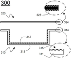
우선, 도 3을 참조하면, 전지케이스(300)는 수납부(313)가 형성되어 있는 제 1 전지케이스(310)와 상기 제 1 전지케이스(310)의 수납부(313)를 감싸는 형태로 상면에 장착되는 제 2 전지케이스(320)를 포함하고 있다.3, the
제 1 전지케이스(310)에는 외주변 부위(314)를 제외한 수납부(313)의 내면에만 전기 절연성 소재(312)가 코팅되어 있다.The
제 1 전지케이스(310)의 외주변 부위에는 요철(315)이 형성되어 있다.The
따라서, 제 1 전지케이스(310)와 제 2 전지케이스(320)의 외주변 부위(314, 324)가 프레스에 의해 가압되는 경우, 제 2 전지케이스(320)의 열용융성 수지 실란트층(323)이 용융되어 보다 넓은 표면에 접착되므로, 보다 높은 밀봉력을 발휘할 수 있다.Therefore, when the outer
상기 구조를 제외한 나머지 구조는 도 2의 전지케이스(도 2의 200)와 동일하므로, 이에 대한 자세한 설명은 생략한다.The remaining structure except for the above structure is the same as that of the battery case 200 (FIG. 2) in FIG. 2, so a detailed description thereof will be omitted.
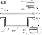
도 4를 참조하면, 전지케이스(400)는 수납부가 형성되어 있는 제 1 전지케이스(410)와 상기 제 1 전지케이스(410)의 수납부(413)를 감싸는 형태로 상면에 장착되는 제 2 전지케이스(420)를 포함하고 있다.4, the
제 2 전지케이스(420)는 알루미늄 플레이트(421)로 이루어져 있으며, 제 1 전지케이스(410)의 수납부(413)와 대면하는 내면에 전기 절연성 소재(423)가 코팅되어 있는 구조로 이루어져 있다.The
따라서, 제 2 전지케이스(420)는 라미네이트 시트로 이루어진 구조에 비해, 상대적으로 높은 강도를 발휘할 수 있어, 전지셀의 구조적 안정성을 향상시킬 수 있다.Therefore, the
또한, 제 2 전지케이스(420)는 내면이, 제 1 전지케이스(410)의 내면에 코팅되어 있는 전기 절연성 소재(412)와 동일한 소재의 전기 절연성 소재(423)로 코팅되어 있어, 제 1 전지케이스(410)의 수납부(413)에 장착되는 전극조립체와 제 2 전지케이스(420)를 이루는 알루미늄 플레이트(421) 사이가 전기적으로 절연되어, 안전성을 향상시킬 수 있으며, 제 1 전지케이스(410)와 제 2 전지케이스(420)의 외주변 부위(414, 424)가 프레스에 의해 가압되는 경우, 제 1 전지케이스(410)의 전기 절연성 소재(412)와 제 2 전지케이스(420)의 전기 절연성 소재(423)가 용융되어, 서로 접착 및 밀봉된다.The inner surface of the
상기 제 2 전지케이스(420)를 제외한 나머지 구조는 도 2의 전지케이스(도 2의 200)와 동일하므로, 이에 대한 자세한 설명은 생략한다.The remaining structure except for the
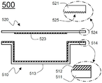
도 5를 참조하면, 전지케이스(500)는 수납부가 형성되어 있는 제 1 전지케이스(510)와 상기 제 1 전지케이스(510)의 수납부(513)를 감싸는 형태로 상면에 장착되는 제 2 전지케이스(520)를 포함하고 있다.5, the
제 1 전지케이스(510)는 도 2의 제 1 전지케이스(도 2의 210)와 동일한 구조로 이루어져 있다.The
제 2 전지케이스(520)는 알루미늄 플레이트(521)로 이루어져 있으며, 제 1 전지케이스(510)의 수납부(513)와 대면하는 내면에 전기 절연성 소재(523)가 코팅되어 있는 구조로 이루어져 있다.The
제 2 전지케이스(520)의 내면에 코팅되어 있는 전기 절연성 소재(523)는 제 2 전지케이스(520)의 외주변 부위(524)를 제외한 제 1 전지케이스(510)의 수납부(513)에 대응되는 부위에만 코팅되어 있다.The electrically insulating
제 2 전지케이스(520)의 외주변 부위(524)에는 요철(525)이 형성되어 있다.The outer
따라서, 전지케이스(500)는 전체적인 강도가 향상되는 동시에, 제 1 전지케이스(510)와 제 2 전지케이스(520)의 외주변 부위(514, 524)가 프레스에 의해 가압되는 경우, 제 1 전지케이스(510)의 전기 절연성 소재(512)가 용융되어 제 2 전지케이스(520)의 외주변 부위(524)에서 보다 넓은 표면에 접착되므로, 보다 높은 밀봉력을 발휘할 수 있다.Therefore, when the
본 발명이 속한 분야에서 통상의 지식을 가진 자라면 상기 내용을 바탕으로 본 발명의 범주내에서 다양한 응용 및 변형을 행하는 것이 가능할 것이다.Those skilled in the art will appreciate that various modifications, additions and substitutions are possible, without departing from the scope and spirit of the invention as disclosed in the accompanying claims.
Claims (22)
상기 전극조립체가 내장되는 수납부가 형성되어 있는 제 1 전지케이스; 및
상기 수납부를 감싸도록 제 1 전지케이스 상에 장착되는 제 2 전지케이스;
를 포함하고,
상기 제 1 전지케이스는 금속 소재로 이루어져 있으며, 내면이 전기 절연성 소재로 코팅되어 있는 것을 특징으로 하는 전지셀.An electrode assembly having a separator structure sandwiched between an anode, a cathode, and an anode and a cathode;
A first battery case having a housing portion in which the electrode assembly is housed; And
A second battery case mounted on the first battery case to enclose the storage unit;
Lt; / RTI >
Wherein the first battery case is made of a metal material and the inner surface is coated with an electrically insulating material.
Priority Applications (1)
| Application Number | Priority Date | Filing Date | Title |
|---|---|---|---|
| KR1020150145280A KR102157150B1 (en) | 2015-10-19 | 2015-10-19 | Battery Cell Comprising Inner Surface Coated with Electrical Insulating Material |
Applications Claiming Priority (1)
| Application Number | Priority Date | Filing Date | Title |
|---|---|---|---|
| KR1020150145280A KR102157150B1 (en) | 2015-10-19 | 2015-10-19 | Battery Cell Comprising Inner Surface Coated with Electrical Insulating Material |
Publications (2)
| Publication Number | Publication Date |
|---|---|
| KR20170045564A true KR20170045564A (en) | 2017-04-27 |
| KR102157150B1 KR102157150B1 (en) | 2020-09-18 |
Family
ID=58702713
Family Applications (1)
| Application Number | Title | Priority Date | Filing Date |
|---|---|---|---|
| KR1020150145280A KR102157150B1 (en) | 2015-10-19 | 2015-10-19 | Battery Cell Comprising Inner Surface Coated with Electrical Insulating Material |
Country Status (1)
| Country | Link |
|---|---|
| KR (1) | KR102157150B1 (en) |
Cited By (10)
| Publication number | Priority date | Publication date | Assignee | Title |
|---|---|---|---|---|
| KR102208159B1 (en) | 2020-10-27 | 2021-01-28 | 정치효 | Auto cleaning apparatus of battery case |
| KR102235529B1 (en) | 2020-10-27 | 2021-04-05 | 정치효 | Auto inner coating apparatus of battery case |
| KR102235526B1 (en) | 2020-10-27 | 2021-04-05 | 정치효 | Auto masking apparatus of battery case |
| KR102235524B1 (en) | 2020-10-27 | 2021-04-06 | 정치효 | Powder coating system and method of battery case |
| KR102237765B1 (en) | 2021-02-26 | 2021-04-08 | 정치효 | Powder coating system of battery case |
| KR102237766B1 (en) | 2021-02-26 | 2021-04-08 | 정치효 | Inner coating apparatus of battery case |
| KR102419024B1 (en) | 2021-07-27 | 2022-07-11 | 정치효 | Horizontal type inner coating apparatus of battery case |
| KR102506639B1 (en) | 2022-07-08 | 2023-03-07 | 정치효 | Powder suction apparatus of battery case |
| KR20230076103A (en) | 2021-11-23 | 2023-05-31 | 주식회사 엘지에너지솔루션 | Pouch type secondary battery and method thereof |
| WO2023229388A1 (en) * | 2022-05-25 | 2023-11-30 | 주식회사 엘지에너지솔루션 | Secondary battery module and secondary battery used therefor |
Citations (9)
| Publication number | Priority date | Publication date | Assignee | Title |
|---|---|---|---|---|
| KR20040048295A (en) * | 2002-12-02 | 2004-06-07 | 히다치 막셀 가부시키가이샤 | Battery |
| KR20070091877A (en) * | 2006-03-08 | 2007-09-12 | 주식회사 엘지화학 | Secondary battery of improved sealability |
| KR20070112488A (en) * | 2006-05-22 | 2007-11-27 | 주식회사 엘지화학 | Laminate sheet for battery case and lithium secondary battery employed with the same |
| KR20100099532A (en) * | 2009-03-03 | 2010-09-13 | 주식회사 엘지화학 | Laminate sheet for battery case and lithium secondary battery using the same |
| KR20110073837A (en) * | 2009-12-24 | 2011-06-30 | 주식회사 루트제이드 | Secondry battery |
| KR20120056316A (en) * | 2010-11-24 | 2012-06-04 | 주식회사 엘지화학 | Process of Improved Productivity for Preparation of Secondary Battery |
| KR20120060315A (en) * | 2010-12-02 | 2012-06-12 | 주식회사 엘지화학 | Secondary Battery of Improved Insulating Property |
| KR20120113527A (en) * | 2011-04-05 | 2012-10-15 | 삼성에스디아이 주식회사 | Case for secondary battery and secondary battery having the same |
| KR20140143150A (en) * | 2012-02-29 | 2014-12-15 | 닛신 세이코 가부시키가이샤 | Exterior material for laminated battery, method for manufacturing exterior material for laminated battery, method for manufacturing laminated battery and laminated battery |
-
2015
- 2015-10-19 KR KR1020150145280A patent/KR102157150B1/en active IP Right Grant
Patent Citations (9)
| Publication number | Priority date | Publication date | Assignee | Title |
|---|---|---|---|---|
| KR20040048295A (en) * | 2002-12-02 | 2004-06-07 | 히다치 막셀 가부시키가이샤 | Battery |
| KR20070091877A (en) * | 2006-03-08 | 2007-09-12 | 주식회사 엘지화학 | Secondary battery of improved sealability |
| KR20070112488A (en) * | 2006-05-22 | 2007-11-27 | 주식회사 엘지화학 | Laminate sheet for battery case and lithium secondary battery employed with the same |
| KR20100099532A (en) * | 2009-03-03 | 2010-09-13 | 주식회사 엘지화학 | Laminate sheet for battery case and lithium secondary battery using the same |
| KR20110073837A (en) * | 2009-12-24 | 2011-06-30 | 주식회사 루트제이드 | Secondry battery |
| KR20120056316A (en) * | 2010-11-24 | 2012-06-04 | 주식회사 엘지화학 | Process of Improved Productivity for Preparation of Secondary Battery |
| KR20120060315A (en) * | 2010-12-02 | 2012-06-12 | 주식회사 엘지화학 | Secondary Battery of Improved Insulating Property |
| KR20120113527A (en) * | 2011-04-05 | 2012-10-15 | 삼성에스디아이 주식회사 | Case for secondary battery and secondary battery having the same |
| KR20140143150A (en) * | 2012-02-29 | 2014-12-15 | 닛신 세이코 가부시키가이샤 | Exterior material for laminated battery, method for manufacturing exterior material for laminated battery, method for manufacturing laminated battery and laminated battery |
Cited By (10)
| Publication number | Priority date | Publication date | Assignee | Title |
|---|---|---|---|---|
| KR102208159B1 (en) | 2020-10-27 | 2021-01-28 | 정치효 | Auto cleaning apparatus of battery case |
| KR102235529B1 (en) | 2020-10-27 | 2021-04-05 | 정치효 | Auto inner coating apparatus of battery case |
| KR102235526B1 (en) | 2020-10-27 | 2021-04-05 | 정치효 | Auto masking apparatus of battery case |
| KR102235524B1 (en) | 2020-10-27 | 2021-04-06 | 정치효 | Powder coating system and method of battery case |
| KR102237765B1 (en) | 2021-02-26 | 2021-04-08 | 정치효 | Powder coating system of battery case |
| KR102237766B1 (en) | 2021-02-26 | 2021-04-08 | 정치효 | Inner coating apparatus of battery case |
| KR102419024B1 (en) | 2021-07-27 | 2022-07-11 | 정치효 | Horizontal type inner coating apparatus of battery case |
| KR20230076103A (en) | 2021-11-23 | 2023-05-31 | 주식회사 엘지에너지솔루션 | Pouch type secondary battery and method thereof |
| WO2023229388A1 (en) * | 2022-05-25 | 2023-11-30 | 주식회사 엘지에너지솔루션 | Secondary battery module and secondary battery used therefor |
| KR102506639B1 (en) | 2022-07-08 | 2023-03-07 | 정치효 | Powder suction apparatus of battery case |
Also Published As
| Publication number | Publication date |
|---|---|
| KR102157150B1 (en) | 2020-09-18 |
Similar Documents
| Publication | Publication Date | Title |
|---|---|---|
| KR101776885B1 (en) | Prismatic Battery Cell Having Two or More Case Members | |
| KR102157150B1 (en) | Battery Cell Comprising Inner Surface Coated with Electrical Insulating Material | |
| KR101826861B1 (en) | Secondary Battery and Battery Module Having the Same | |
| KR102018849B1 (en) | Battery Cell Comprising Electrode Lead Having Protruding Extension Part and Tab Connection Part | |
| EP3327854B1 (en) | Battery cell including electrode lead containing gas adsorbent | |
| KR20170055144A (en) | Pouch-typed Battery Cell Including Double Folded Sealing Portion | |
| KR20170089276A (en) | Device for Manufacturing Battery Cell Having One-Stop Folding Member | |
| KR101933655B1 (en) | Battery Cell Having Recess Portion Formed at Portion of Electrode Tab | |
| KR20180028200A (en) | Battery Case Sealing Device Having Wrinkle Removal Function | |
| KR101936074B1 (en) | Battery Cell Comprising Electrolyte-Containing Member for Supplying Electrolyte | |
| KR101794939B1 (en) | Battery Cell Comprising Electrode Assemblies of Different Size and Method for Preparing the Same | |
| KR101725921B1 (en) | Battery Cell Comprising Unit Cell Stacks and Intermediate Stack Cell | |
| KR20170044416A (en) | Pouch-typed Battery Cell Having Electrode Lead of Folded Structure | |
| KR101671386B1 (en) | Method of Secondary Battery Using Protective Case | |
| KR20160074209A (en) | Can Type Curved Battery and Method for Manufacturing the Same | |
| KR20170082239A (en) | Battery Cell Having Extended Electrode Lead | |
| KR101554141B1 (en) | Plate-Typed Battery Cell | |
| KR101726767B1 (en) | Battery Pack Having Elastic Rib for Fixing Battery Cell | |
| KR101778670B1 (en) | Battery Module Based upon Interpenetrating Coolant Channel Structure | |
| KR20170088024A (en) | Pouch-typed Battery Cell Having Height Difference between Bent Sealing Portion and Electrode Assembly-receiving Part | |
| KR20170110300A (en) | Method for Manufacturing Battery Cell by Pre-Heating Electrode Lead | |
| KR101864882B1 (en) | Battery Case Comprising PTFE-Based Material | |
| KR101738542B1 (en) | Battery Cell Having Film for Fixing of Electrode Assembly | |
| KR101798929B1 (en) | Battery Case Having Label for Reinforcement and Secondary Battery Comprising the Same | |
| KR20180063454A (en) | Battery Module Having Module Compression Limiting Structure |
Legal Events
| Date | Code | Title | Description |
|---|---|---|---|
| A201 | Request for examination | ||
| E902 | Notification of reason for refusal | ||
| E902 | Notification of reason for refusal | ||
| E701 | Decision to grant or registration of patent right |