KR20170043331A - Cooling apparatus using electrochemical reaction - Google Patents
Cooling apparatus using electrochemical reaction Download PDFInfo
- Publication number
- KR20170043331A KR20170043331A KR1020150142953A KR20150142953A KR20170043331A KR 20170043331 A KR20170043331 A KR 20170043331A KR 1020150142953 A KR1020150142953 A KR 1020150142953A KR 20150142953 A KR20150142953 A KR 20150142953A KR 20170043331 A KR20170043331 A KR 20170043331A
- Authority
- KR
- South Korea
- Prior art keywords
- chamber
- refrigerant
- liquefied
- vaporized
- hydrogen gas
- Prior art date
Links
- 238000001816 cooling Methods 0.000 title abstract description 66
- 238000003487 electrochemical reaction Methods 0.000 title abstract description 3
- 239000003507 refrigerant Substances 0.000 claims abstract description 225
- UFHFLCQGNIYNRP-UHFFFAOYSA-N Hydrogen Chemical compound [H][H] UFHFLCQGNIYNRP-UHFFFAOYSA-N 0.000 claims abstract description 72
- 239000001257 hydrogen Substances 0.000 claims abstract description 47
- 229910052739 hydrogen Inorganic materials 0.000 claims abstract description 47
- 239000003054 catalyst Substances 0.000 claims abstract description 13
- 238000003825 pressing Methods 0.000 claims abstract description 7
- GPRLSGONYQIRFK-UHFFFAOYSA-N hydron Chemical compound [H+] GPRLSGONYQIRFK-UHFFFAOYSA-N 0.000 claims abstract 3
- 239000012528 membrane Substances 0.000 claims description 65
- 239000003792 electrolyte Substances 0.000 claims description 64
- -1 hydrogen ions Chemical class 0.000 claims description 33
- 238000000034 method Methods 0.000 claims description 20
- 230000003197 catalytic effect Effects 0.000 claims description 13
- QGZKDVFQNNGYKY-UHFFFAOYSA-N Ammonia Chemical compound N QGZKDVFQNNGYKY-UHFFFAOYSA-N 0.000 claims description 8
- 239000000919 ceramic Substances 0.000 claims description 6
- 230000003647 oxidation Effects 0.000 claims description 6
- 238000007254 oxidation reaction Methods 0.000 claims description 6
- 230000009467 reduction Effects 0.000 claims description 5
- XLYOFNOQVPJJNP-UHFFFAOYSA-N water Substances O XLYOFNOQVPJJNP-UHFFFAOYSA-N 0.000 claims description 5
- 229910021529 ammonia Inorganic materials 0.000 claims description 4
- 239000012078 proton-conducting electrolyte Substances 0.000 claims description 4
- LFQSCWFLJHTTHZ-UHFFFAOYSA-N Ethanol Chemical compound CCO LFQSCWFLJHTTHZ-UHFFFAOYSA-N 0.000 claims description 3
- 238000007599 discharging Methods 0.000 claims description 3
- 239000003125 aqueous solvent Substances 0.000 claims description 2
- 230000005611 electricity Effects 0.000 abstract 1
- 239000007788 liquid Substances 0.000 description 9
- 230000032258 transport Effects 0.000 description 7
- BASFCYQUMIYNBI-UHFFFAOYSA-N platinum Chemical compound [Pt] BASFCYQUMIYNBI-UHFFFAOYSA-N 0.000 description 6
- 239000000463 material Substances 0.000 description 5
- 239000012466 permeate Substances 0.000 description 4
- HEMHJVSKTPXQMS-UHFFFAOYSA-M Sodium hydroxide Chemical compound [OH-].[Na+] HEMHJVSKTPXQMS-UHFFFAOYSA-M 0.000 description 3
- 238000010586 diagram Methods 0.000 description 3
- 239000007789 gas Substances 0.000 description 3
- 230000008569 process Effects 0.000 description 3
- 238000005057 refrigeration Methods 0.000 description 3
- 229920000557 Nafion® Polymers 0.000 description 2
- FAPWRFPIFSIZLT-UHFFFAOYSA-M Sodium chloride Chemical compound [Na+].[Cl-] FAPWRFPIFSIZLT-UHFFFAOYSA-M 0.000 description 2
- 238000009792 diffusion process Methods 0.000 description 2
- 239000012530 fluid Substances 0.000 description 2
- 239000000203 mixture Substances 0.000 description 2
- 239000010955 niobium Substances 0.000 description 2
- 229910052697 platinum Inorganic materials 0.000 description 2
- 239000010936 titanium Substances 0.000 description 2
- 230000008016 vaporization Effects 0.000 description 2
- NWUYHJFMYQTDRP-UHFFFAOYSA-N 1,2-bis(ethenyl)benzene;1-ethenyl-2-ethylbenzene;styrene Chemical compound C=CC1=CC=CC=C1.CCC1=CC=CC=C1C=C.C=CC1=CC=CC=C1C=C NWUYHJFMYQTDRP-UHFFFAOYSA-N 0.000 description 1
- RTAQQCXQSZGOHL-UHFFFAOYSA-N Titanium Chemical compound [Ti] RTAQQCXQSZGOHL-UHFFFAOYSA-N 0.000 description 1
- 230000009471 action Effects 0.000 description 1
- 238000005341 cation exchange Methods 0.000 description 1
- 239000003729 cation exchange resin Substances 0.000 description 1
- 125000002091 cationic group Chemical group 0.000 description 1
- 150000001768 cations Chemical class 0.000 description 1
- 230000008859 change Effects 0.000 description 1
- NEHMKBQYUWJMIP-NJFSPNSNSA-N chloro(114C)methane Chemical compound [14CH3]Cl NEHMKBQYUWJMIP-NJFSPNSNSA-N 0.000 description 1
- 238000009833 condensation Methods 0.000 description 1
- 230000005494 condensation Effects 0.000 description 1
- 239000002826 coolant Substances 0.000 description 1
- 230000000694 effects Effects 0.000 description 1
- 238000000909 electrodialysis Methods 0.000 description 1
- 238000005868 electrolysis reaction Methods 0.000 description 1
- 229910000856 hastalloy Inorganic materials 0.000 description 1
- 239000001307 helium Substances 0.000 description 1
- 229910052734 helium Inorganic materials 0.000 description 1
- SWQJXJOGLNCZEY-UHFFFAOYSA-N helium atom Chemical compound [He] SWQJXJOGLNCZEY-UHFFFAOYSA-N 0.000 description 1
- 238000000752 ionisation method Methods 0.000 description 1
- 150000002500 ions Chemical class 0.000 description 1
- 238000004519 manufacturing process Methods 0.000 description 1
- 230000007246 mechanism Effects 0.000 description 1
- 239000002184 metal Substances 0.000 description 1
- 229910052751 metal Inorganic materials 0.000 description 1
- 230000004048 modification Effects 0.000 description 1
- 238000012986 modification Methods 0.000 description 1
- 229910052758 niobium Inorganic materials 0.000 description 1
- GUCVJGMIXFAOAE-UHFFFAOYSA-N niobium atom Chemical compound [Nb] GUCVJGMIXFAOAE-UHFFFAOYSA-N 0.000 description 1
- 238000012856 packing Methods 0.000 description 1
- 239000002245 particle Substances 0.000 description 1
- 239000002798 polar solvent Substances 0.000 description 1
- 238000011946 reduction process Methods 0.000 description 1
- 239000011347 resin Substances 0.000 description 1
- 229920005989 resin Polymers 0.000 description 1
- VSZWPYCFIRKVQL-UHFFFAOYSA-N selanylidenegallium;selenium Chemical compound [Se].[Se]=[Ga].[Se]=[Ga] VSZWPYCFIRKVQL-UHFFFAOYSA-N 0.000 description 1
- 239000011780 sodium chloride Substances 0.000 description 1
- 229910001220 stainless steel Inorganic materials 0.000 description 1
- 239000010935 stainless steel Substances 0.000 description 1
- 229910052719 titanium Inorganic materials 0.000 description 1
- 238000009834 vaporization Methods 0.000 description 1
- 239000003021 water soluble solvent Substances 0.000 description 1
Images

Classifications
-
- F—MECHANICAL ENGINEERING; LIGHTING; HEATING; WEAPONS; BLASTING
- F25—REFRIGERATION OR COOLING; COMBINED HEATING AND REFRIGERATION SYSTEMS; HEAT PUMP SYSTEMS; MANUFACTURE OR STORAGE OF ICE; LIQUEFACTION SOLIDIFICATION OF GASES
- F25D—REFRIGERATORS; COLD ROOMS; ICE-BOXES; COOLING OR FREEZING APPARATUS NOT OTHERWISE PROVIDED FOR
- F25D19/00—Arrangement or mounting of refrigeration units with respect to devices or objects to be refrigerated, e.g. infrared detectors
-
- B—PERFORMING OPERATIONS; TRANSPORTING
- B01—PHYSICAL OR CHEMICAL PROCESSES OR APPARATUS IN GENERAL
- B01J—CHEMICAL OR PHYSICAL PROCESSES, e.g. CATALYSIS OR COLLOID CHEMISTRY; THEIR RELEVANT APPARATUS
- B01J23/00—Catalysts comprising metals or metal oxides or hydroxides, not provided for in group B01J21/00
- B01J23/38—Catalysts comprising metals or metal oxides or hydroxides, not provided for in group B01J21/00 of noble metals
- B01J23/40—Catalysts comprising metals or metal oxides or hydroxides, not provided for in group B01J21/00 of noble metals of the platinum group metals
- B01J23/42—Platinum
-
- F—MECHANICAL ENGINEERING; LIGHTING; HEATING; WEAPONS; BLASTING
- F25—REFRIGERATION OR COOLING; COMBINED HEATING AND REFRIGERATION SYSTEMS; HEAT PUMP SYSTEMS; MANUFACTURE OR STORAGE OF ICE; LIQUEFACTION SOLIDIFICATION OF GASES
- F25B—REFRIGERATION MACHINES, PLANTS OR SYSTEMS; COMBINED HEATING AND REFRIGERATION SYSTEMS; HEAT PUMP SYSTEMS
- F25B15/00—Sorption machines, plants or systems, operating continuously, e.g. absorption type
- F25B15/02—Sorption machines, plants or systems, operating continuously, e.g. absorption type without inert gas
- F25B15/04—Sorption machines, plants or systems, operating continuously, e.g. absorption type without inert gas the refrigerant being ammonia evaporated from aqueous solution
-
- F25B41/003—
-
- F25B41/062—
Abstract
Description
본 발명은 전기 화학 반응에 의해 냉매가 순환되면서 장치를 냉각시키는 냉각 장치에 관한 것이다.BACKGROUND OF THE INVENTION 1. Field of the Invention The present invention relates to a cooling device for cooling an apparatus while a refrigerant is circulated by an electrochemical reaction.
냉각 장치는 냉매가 순환되어 응축 또는 팽창 과정을 거치면서 냉동 사이클을 구현하는 장치이다. 냉각 장치에서 냉매는 증발기에서 열을 흡수하여 기화되고, 압축기(펌프)로부터 압력을 받아 응축기에서 응축되면서 열을 방출하게 된다. 그 후 냉매는 팽창밸브를 거쳐 압력이 낮아지면서 증발기로 이동되는 과정을 거치게 되고, 이러한 순환 과정을 통해 열을 흡수하여 외부로 방출함으로써 연결된 장치를 냉각시킬 수 있게 된다.The cooling device is a device that implements a refrigeration cycle by circulating refrigerant to undergo condensation or expansion. In the cooling system, the refrigerant absorbs heat in the evaporator and is vaporized. The refrigerant is pressurized by the compressor (pump) and condenses in the condenser to release heat. Then, the refrigerant passes through the expansion valve and moves to the evaporator while the pressure is lowered. Through the circulation process, the refrigerant absorbs heat and discharges the refrigerant to the outside, thereby cooling the connected device.
종래의 전기 화학식 냉동사이클 냉각 장치는 수소 기체 및 냉매가 혼합되어 증발기 및 응축기를 거쳐 순환되는 방식으로, 혼합된 수소 기체와 냉매는 증발기를 거치면서 기화된 후 투과막(membrane)을 통과하게 된다. 이때, 기화된 냉매가 투과막 면에서 응축되는 경우가 발생하는데, 이 경우 냉매가 증발기와 연결된 부분에서 응축되면서 증발기 온도가 낮아지지 않고 올라갈 수 있으며, 냉매의 흐름이 원활하지 않게되므로 냉각 효율이 상대적으로 낮아지게 된다.In the conventional electrochemical refrigeration cycle cooling apparatus, hydrogen gas and refrigerant are mixed and circulated through an evaporator and a condenser, and the mixed hydrogen gas and refrigerant pass through a membrane after being vaporized while passing through an evaporator. In this case, the evaporated refrigerant condenses on the permeable membrane surface. In this case, since the refrigerant is condensed at the portion connected to the evaporator, the evaporator temperature can be raised without lowering the temperature, and the refrigerant flow is not smooth, .
즉, 종래의 냉각 장치는 증발기와 응축기 사이에서 온도 차이가 줄어드는 결과를 초래하여 냉각 장치로서의 효율이 낮아지는 문제점이 있다. 또한, 종래의 냉각 장치는 수소 기체와 냉매가 혼합된 상태로 이동하게 되어 그 흐름이 원활하지 못한 문제점이 있다.That is, the conventional cooling device has a problem that the temperature difference between the evaporator and the condenser is reduced, and the efficiency as a cooling device is lowered. In addition, the conventional cooling device has a problem that the flow of hydrogen gas and refrigerant is mixed and the flow thereof is not smooth.
본 발명의 일 목적은, 냉매 및 수소가 증발기, 압축기 및 응축기 사이에서 원활한 흐름을 가지도록 하는 냉각 장치의 구조를 제안하는 것이다.It is an object of the present invention to propose a structure of a cooling device in which refrigerant and hydrogen flow smoothly between an evaporator, a compressor and a condenser.
본 발명의 다른 일 목적은, 냉매 및 수소를 각각 분리 이동시켜 냉각 효율을 높이는 냉각 장치의 구조를 제안하는 것이다.Another object of the present invention is to propose a structure of a cooling device for separating refrigerant and hydrogen from each other to enhance cooling efficiency.
본 발명의 또 다른 일 목적은, 냉매가 원활하게 순환되어 냉각 효율을 높이는 또 다른 냉각 장치의 구조를 제안하는 것이다.Another object of the present invention is to propose a structure of another cooling device in which refrigerant is smoothly circulated to enhance cooling efficiency.
상기한 과제를 실현하기 위한 본 발명의 일 실시예와 관련된 냉각 장치는, 액화된 냉매를 수용하는 제1 챔버를 구비하고, 외부의 열을 흡수하여 상기 액화된 냉매를 기화시키는 증발기; 상기 제1 챔버로부터 기화된 냉매를 전달받고, 수소 기체가 유입되도록 구성되는 제2 챔버; 상기 제2 챔버를 사이에 두고 상기 제1 챔버와 마주보도록 배치되고, 전원부로부터 공급된 전원에 의해 상기 제2 챔버와 접하는 일 측에서 상기 제2 챔버에 유입된 수소 기체를 이온화시키는 촉매부; 및 상기 제2 챔버로부터 상기 기화된 냉매 및 수소 이온을 전달받고, 상기 기화된 냉매에 압력이 인가되어 액화된 냉매 및 상기 수소 이온이 상기 전원부로부터 전자를 공급받아 환원된 수소 기체를 수용하는 제3 챔버를 구비하며, 상기 냉매의 액화에 의해 외부로 열을 방출시키는 응축기를 포함하고, 상기 제3 챔버에 수용된 액화된 냉매 및 수소 기체는 상기 제1 챔버 및 상기 제2 챔버로 각각 분리 이동된다.According to an aspect of the present invention, there is provided a cooling device comprising: an evaporator having a first chamber for receiving liquefied refrigerant and absorbing external heat to vaporize the liquefied refrigerant; A second chamber configured to receive vaporized refrigerant from the first chamber and to introduce hydrogen gas; A catalytic part disposed to face the first chamber with the second chamber interposed therebetween and ionizing the hydrogen gas introduced into the second chamber at one side in contact with the second chamber by a power source supplied from a power source part; And a third chamber for receiving the vaporized refrigerant and hydrogen ions from the second chamber, a refrigerant liquefied by applying pressure to the vaporized refrigerant, and a third refrigerant for receiving the reduced hydrogen gas, And a condenser for discharging heat to the outside by liquefaction of the refrigerant, wherein the liquefied refrigerant and the hydrogen gas accommodated in the third chamber are separated and transferred to the first chamber and the second chamber, respectively.
본 발명과 관련된 일 예에 따르면, 상기 제3 챔버로부터 상기 액화된 냉매 및 수소 기체가 분리 이동되는 통로를 구비하는 배관부를 더 포함하고, 상기 배관부는, 상기 제1 챔버 및 상기 제3 챔버의 하부를 연결하여 상기 제3 챔버에서 액화된 냉매를 상기 제1 챔버로 수송하는 제1 배관; 및 상기 제2 챔버 및 상기 제3 챔버의 상부를 연결하여 상기 제3 챔버에서 환원된 수소 기체를 상기 제2 챔버로 수송하는 제2 배관을 포함한다.According to an embodiment of the present invention, the apparatus further includes a piping section having a passage through which the liquefied refrigerant and the hydrogen gas are separated from the third chamber, and the piping section is connected to the lower part of the first chamber and the lower part of the third chamber A first pipe connected to the first chamber and connected to the third chamber to transport the refrigerant liquefied in the third chamber to the first chamber; And a second conduit connecting the second chamber and the upper portion of the third chamber to transport the hydrogen gas reduced in the third chamber to the second chamber.
본 발명과 관련된 다른 일 예에 따르면, 상기 제2 배관의 일 측에 설치되고, 상기 제2 배관 내의 압력을 조절하여 상기 수소 기체의 이동을 제어하는 팽창밸브를 더 포함할 수 있다.According to another embodiment of the present invention, the apparatus may further include an expansion valve installed at one side of the second pipe and controlling the movement of the hydrogen gas by controlling a pressure in the second pipe.
본 발명과 관련된 일 예에 따르면, 상기 제1 챔버 및 상기 제2 챔버 사이에 개재되어 상기 증발기에 의해 기화된 냉매를 상기 제1 챔버로부터 제2 챔버로 투과되도록 하는 제1 전해질막을 더 포함한다.According to an embodiment of the present invention, the apparatus further includes a first electrolyte membrane interposed between the first chamber and the second chamber, for allowing refrigerant vaporized by the evaporator to pass from the first chamber to the second chamber.
본 발명과 관련된 일 예에 따르면, 상기 제2 챔버 및 상기 제3 챔버 사이에 개재되어 상기 기화된 냉매 및 수소 이온을 상기 제2 챔버로부터 상기 제3 챔버로 투과되도록 하는 제2 전해질막을 더 포함한다.According to an embodiment related to the present invention, the apparatus further includes a second electrolyte film interposed between the second chamber and the third chamber to allow the vaporized refrigerant and hydrogen ions to pass from the second chamber to the third chamber .
본 발명과 관련된 일 예에 따르면, 상기 제2 전해질막은 상기 촉매부에 의해 형성되는 수소 이온이 이동 가능하도록 양성자 전도 전해질막으로 이루어질 수 있다.According to an embodiment of the present invention, the second electrolyte membrane may be formed of a proton conducting electrolyte membrane so that hydrogen ions formed by the catalyst unit can move.
본 발명과 관련된 일 예에 따르면, 상기 촉매부는 상기 제2 전해질막의 외측에 형성되고, 상기 제2 챔버 및 상기 제3 챔버의 사이에 위치될 수 있다.According to one example related to the present invention, the catalyst portion is formed outside the second electrolyte membrane, and may be positioned between the second chamber and the third chamber.
본 발명과 관련된 일 예에 따르면, 상기 촉매부는 상기 제2 챔버와 접하는 일 측에서 상기 제2 챔버 내의 상기 수소 기체의 산화를 유도하고, 상기 제3 챔버와 접하는 타 측에서 상기 제3 챔버 내의 상기 수소 이온의 환원을 유도할 수 있다.According to an embodiment of the present invention, the catalytic portion induces oxidation of the hydrogen gas in the second chamber at a side contacting the second chamber, and at the other side in contact with the third chamber, It is possible to induce reduction of hydrogen ions.
본 발명과 관련된 일 예에 따르면, 상기 증발기는 제2 챔버와 마주보도록 배치된다.According to one embodiment of the present invention, the evaporator is disposed to face the second chamber.
본 발명과 관련된 일 예에 따르면, 상기 냉매는 수용성 용매로서 물(H2O), 알코올(alcohol) 및 암모니아(NH3) 중 적어도 어느 하나이거나 2개 이상의 혼합물이다.According to one embodiment of the present invention, the refrigerant is at least one of water (H 2 O), alcohol and ammonia (NH 3 ) or a mixture of two or more as an aqueous solvent.
본 발명과 관련된 일 예에 따르면, 상기 전원부는, 상기 제2 챔버에 수용된 수소 기체는 산화되고 상기 제3 챔버에 수용된 수소 이온은 환원되도록, 상기 제2 챔버 및 상기 제3 챔버에 각각 (+)극 및 (-)극이 연결되며, 기설정된 전압을 공급하여 상기 냉매의 전기 분해를 방지한다.According to one example related to the present invention, the power source unit is connected to the second chamber and the third chamber, respectively, so that the hydrogen gas contained in the second chamber is oxidized and the hydrogen ions contained in the third chamber are reduced. And a negative (-) electrode are connected, and a predetermined voltage is supplied to prevent the refrigerant from being electrolyzed.
본 발명과 관련된 일 예에 따르면, 상기 제3 챔버에서 상기 냉매가 액화되면서 발생하는 열이 외부로 방출되도록 상기 응축기의 일 측에 구비되는 열교환기를 더 포함한다.According to an embodiment of the present invention, the heat exchanger further includes a heat exchanger provided on one side of the condenser so that heat generated when the refrigerant is liquefied in the third chamber is discharged to the outside.
상기한 또 다른 과제를 실현하기 위한 본 발명의 일 실시예와 관련된 냉각 장치는, 액화된 냉매를 수용하는 제1 챔버를 구비하고, 외부의 열을 흡수하여 상기 액화된 냉매를 기화시키는 증발기; 상기 제1 챔버로부터 기화된 냉매를 전달받아 수용하는 제2 챔버; 상기 제2 챔버로부터 기화된 냉매를 전달받고, 상기 기화된 냉매에 압력이 인가되어 액화된 냉매를 수용하는 제3 챔버를 구비하며, 상기 냉매의 액화에 의해 외부로 열을 방출시키는 응축기; 및 상기 제2 챔버 및 상기 제3 챔버 사이에 개재되어 설정된 전압의 인가로 상기 기화된 냉매를 상기 제2 챔버로부터 상기 제3 챔버로 투과시키는 전기 삼투압 펌프를 포함하고, 상기 제3 챔버에서 액화된 냉매 및 상기 제3 챔버에서 기화된 상태로 잔존하는 냉매는 상기 제1 챔버 및 상기 제2 챔버로 각각 분리 이동될 수 있다.According to another aspect of the present invention, there is provided a cooling apparatus comprising: an evaporator having a first chamber for receiving liquefied refrigerant and absorbing external heat to vaporize the liquefied refrigerant; A second chamber for receiving and receiving the vaporized refrigerant from the first chamber; And a third chamber receiving the vaporized refrigerant from the second chamber and receiving the liquefied refrigerant by applying pressure to the vaporized refrigerant, wherein the condenser discharges heat to the outside by liquefying the refrigerant; And an electroosmotic pump for passing the vaporized refrigerant from the second chamber to the third chamber by application of a voltage interposed between the second chamber and the third chamber, The refrigerant and the refrigerant remaining in the vaporized state in the third chamber may be separated from the first chamber and the second chamber, respectively.
본 발명과 관련된 일 예에 따르면, 상기 제1 챔버 및 상기 제2 챔버 사이에 개재되어 상기 증발기에 의해 기화된 냉매를 상기 제1 챔버로부터 제2 챔버로 투과되도록 하는 제1 전해질막을 더 포함한다.According to an embodiment of the present invention, the apparatus further includes a first electrolyte membrane interposed between the first chamber and the second chamber, for allowing refrigerant vaporized by the evaporator to pass from the first chamber to the second chamber.
본 발명과 관련된 또 다른 일 예에 따르면, 상기 전기 삼투압 펌프는 다공성 세라믹 막으로 형성되고, 상기 다공성 세라믹 막에 존재하는 미세 채널을 통해 상기 기화된 냉매가 이동된다.According to another embodiment of the present invention, the electroosmotic pump is formed of a porous ceramic membrane, and the vaporized refrigerant is moved through fine channels existing in the porous ceramic membrane.
본 발명과 관련된 일 예에 따르면, 상기 제2 챔버로부터 상기 액화된 냉매 및 기화된 냉매를 각각 분리 이동시키는 통로를 구비하는 배관부를 더 포함하고, 상기 배관부는, 상기 제1 챔버 및 상기 제2 챔버의 하단을 연결하여 상기 제2 챔버에서 액화된 냉매를 상기 제1 챔버로 수송하는 제1 배관; 및 상기 제2 챔버 및 상기 제3 챔버의 상단을 연결하여 상기 제2 챔버에서 기화된 상태로 잔존하는 냉매를 상기 제3 챔버로 수송하는 제2 배관을 포함한다.According to an embodiment of the present invention, the apparatus further includes a piping section having a passage for separating the liquefied refrigerant and the vaporized refrigerant from the second chamber, respectively, and the piping section is connected to the first chamber and the second chamber A first pipe connecting the lower ends of the first and second chambers to the first chamber for transporting the refrigerant liquefied in the second chamber to the first chamber; And a second conduit connecting the upper ends of the second chamber and the third chamber to transport the remaining refrigerant vaporized in the second chamber to the third chamber.
본 발명과 관련된 일 예에 따르면, 상기 제2 배관은 일 측에 연결되는 팽창밸브를 통해 압력이 조절되어 상기 기화된 상태로 잔존하는 냉매의 이동을 제어한다.According to an embodiment of the present invention, the second pipe controls the movement of the refrigerant remaining in the vaporized state by controlling the pressure through an expansion valve connected to one side.
상기한 또 다른 과제를 실현하기 위한 본 발명의 일 실시예와 관련된 냉각 장치는, 액화된 냉매를 수용하는 제1 챔버를 구비하고, 외부의 열을 흡수하여 상기 액화된 냉매를 기화시키는 복수 개의 증발기; 상기 제1 챔버와 제1 전해질막을 사이에 두고 위치되어 상기 제1 전해질막을 거쳐 상기 제1 챔버로부터 기화된 냉매를 전달받는 제2 챔버; 및 진공 펌프의 작동에 의해 상기 제2 챔버로부터 기화된 냉매를 전달받고, 상기 기화된 냉매에 압력이 인가되어 상기 기화된 냉매가 액화되어 외부로 열이 방출되도록 하는 응축기를 포함하며, 상기 응축기에서 액화된 냉매는 상기 복수 개의 증발기에 구비되는 상기 제1 챔버들로 각각 이동된다.According to another aspect of the present invention, there is provided a cooling apparatus including a first chamber for accommodating liquefied refrigerant, a plurality of evaporators for absorbing external heat to vaporize the liquefied refrigerant, ; A second chamber positioned between the first chamber and the first electrolyte membrane and receiving vaporized refrigerant from the first chamber through the first electrolyte membrane; And a condenser that receives vaporized refrigerant from the second chamber by the operation of a vacuum pump and applies pressure to the vaporized refrigerant to cause the vaporized refrigerant to be liquefied to discharge heat to the outside, And the liquefied refrigerant is respectively transferred to the first chambers provided in the plurality of evaporators.
본 발명과 관련된 일 예에 따르면, 상기 진공 펌프는 상기 제2 챔버 및 상기 응축기를 연결하는 배관의 일 측에 위치되어 기화된 냉매를 상기 제2 챔버로부터 방출시킨다.According to an embodiment of the present invention, the vacuum pump is disposed at one side of a pipe connecting the second chamber and the condenser, and discharges vaporized refrigerant from the second chamber.
상기와 같은 구성의 본 발명에 의하면, 복수 개의 챔버를 이용하여 냉매 및 수소를 별도로 분리 이동시킴으로써 냉각 장치 내에서 원활한 흐름을 가지도록 할 수 있다.According to the present invention as described above, refrigerant and hydrogen are separately separated and moved using a plurality of chambers, so that a smooth flow can be obtained in the cooling device.
상기와 같은 구조에 의하면, 냉매 및 수소가 별도의 배관부를 통해 분리 이동되어 냉각 장치 내에서 원활한 순환이 가능하여 냉각 효율이 높아지게 된다.According to the above structure, the refrigerant and the hydrogen are separated and moved through the separate piping portion, so that the refrigerant can circulate smoothly in the cooling device, thereby improving the cooling efficiency.
또한, 수소의 이온화 없이 전기 삼투압 펌프 및 진공 펌프를 이용하여 냉매의 원활한 흐름을 도모할 수 있으므로 냉각 효율을 높일 수 있다.In addition, since the osmosis pump and the vacuum pump can be used to smoothly flow the refrigerant without hydrogen ionization, the cooling efficiency can be increased.
도 1은 본 발명의 냉각 장치의 일 예를 보인 개념도.
도 2는 도 1에 도시된 냉각 장치를 다르게 나타낸 개념도.
도 3는 도 1에 도시된 냉각 장치의 제2 전해질막에서 수소 및 냉매가 투과되는 과정을 나타내는 개념도.
도 4는 도 1의 냉각 장치의 다른 실시예를 나타내는 개념도.
도 5는 다른 실시예로서 전기 삼투압 펌프를 포함하는 냉각 장치를 나타내는 개념도.
도 6은 또 다른 실시예로서 진공 펌프를 포함하는 냉각 장치를 나타내는 개념도.1 is a conceptual diagram showing an example of a cooling device of the present invention.
FIG. 2 is a conceptual view showing the cooling device shown in FIG. 1 differently. FIG.
3 is a conceptual view showing a process of passing hydrogen and a refrigerant through the second electrolyte membrane of the cooling device shown in FIG.
4 is a conceptual view showing another embodiment of the cooling device of Fig.
5 is a conceptual view showing a cooling device including an electroosmotic pump as another embodiment;
6 is a conceptual view showing a cooling device including a vacuum pump as another embodiment;
이하, 본 발명에 관련된 냉각 장치에 대하여 도면을 참조하여 보다 상세하게 설명한다.Hereinafter, a cooling apparatus according to the present invention will be described in detail with reference to the drawings.
본 명세서에서는 서로 다른 실시예라도 동일·유사한 구성에 대해서는 동일·유사한 참조번호를 부여하고, 그 설명은 처음 설명으로 갈음한다. 본 명세서에서 사용되는 단수의 표현은 문맥상 명백하게 다르게 뜻하지 않는 한 복수의 표현을 포함한다.In the present specification, the same or similar reference numerals are given to different embodiments in the same or similar configurations. As used herein, the singular forms "a", "an" and "the" include plural referents unless the context clearly dictates otherwise.
본 발명의 냉각 장치(100, 200, 300)는 연결된 장치의 냉각을 위해 응용되어 사용될 수 있다. 이하, 냉각 장치의 구조 및 메커니즘에 대해 설명하기로 한다.The
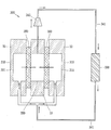
도 1은 본 발명의 냉각 장치(100)의 일 예를 나타낸다.Fig. 1 shows an example of a
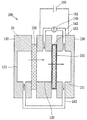
냉각 장치(100)는 수소의 이온화를 이용하여 냉매를 순환시켜 냉동 사이클을 구현하게 된다. 본 발명의 냉각 장치(100)는 제1 챔버(111)를 포함하는 증발기(110), 제2 챔버(120), 제3 챔버(131)를 포함하는 응축기(130) 및 촉매부(153)를 포함한다.The
도 1의 냉각 장치(100)는 세 개의 챔버(111, 120, 131)를 포함하고, 전해질막(150, 151)이 챔버(111, 120, 131)들 사이에 개재되는 구조를 가진다. 여기서 챔버(chamber)란 물질을 수용 가능하고 물리적으로 구분된 공간을 의미하는 것으로, 도 1에서 각 챔버(111, 120, 131)는 냉매 및 수소 기체 혹은 수소 이온을 수용할 수 있다.1 includes three
이하, 도 1을 통해 나타난 냉각 장치(100)의 각각의 구성에 대해 살펴보겠다.Hereinafter, each configuration of the
증발기(110)는 팽창밸브(145)와 제1 배관(141)을 거쳐 유입된 액체 냉매를 주위의 공간 또는 피냉각물체와 열교환시켜 냉매가 기화되면서 열을 흡수하는 장치이다. 증발기(110)는 건식, 반만액식, 만액식 및 액순환식의 종류가 있으나, 본 발명에서의 증발기(110)는 특별히 한정되지 않고 다양한 종류로 구성이 가능하다.The
증발기(110)는 도 1에서 보는 바와 같이 액화된 냉매를 수용하는 제1 챔버(111)를 구비하고, 액화된 냉매가 기화되면서 외부로부터 열을 흡수하게 된다. 증발기(110)는 내부에 제1 챔버(111)가 구비되고, 제1 챔버(111)를 둘러싸는 케이스(10)로 이루어진다. 케이스(10)는 통상적으로 열전도율이 큰 금속으로 이루어지는 것이 일반적일 것이다.1, the
응축기(130)는 냉매의 액화를 통해 열을 외부로 방출하는 장치를 의미한다. 응축기(130)는 냉매를 압축하여 냉매를 액화시키면서 흡수한 열을 제거하게 된다. 응축기(130)의 종류로는 수냉, 공냉 및 증발식이 있고, 사용 목적에 따라 여러 종류의 응축기(130)가 사용될 수 있다. 본 발명에서 사용되는 응축기(130)는 특정 종류에만 한정되지는 않을 것이다.The
도 1의 냉각 장치(100)는 각 챔버(chamber)를 포함하고, 챔버(111, 120, 131)는 제1 챔버(111), 제2 챔버(120) 및 제3 챔버(131)로 구성된다. 챔버(chamber)는 물질이 수용 가능한 공간을 구비하면 되므로, 그 형상에는 특별한 제한이 없으며, 각 도면에 나타난 챔버의 형상은 하나의 예시에 불과하다. 제1 챔버(111)는 증발기(110)의 내부에 구비되고, 제3 챔버(131)는 응축기(130)의 내부에 구비되며, 제2 챔버(120)는 제1 챔버(111)와 제2 챔버(120)의 사이에 위치되는 구조를 가진다.1 includes
각각의 챔버(111, 120, 131)에 대해 살펴보면, 제1 챔버(111)는 제3 챔버(131)와 연결된 제1 배관(141)을 통해 제3 챔버(131)로부터 응축된 냉매를 전달받는다.The
제2 챔버(120)는 제1 챔버(111)와 전해질막을 사이에 두고 위치되고, 여기서 전해질막은 제1 전해질막(150)이라 한다. 제2 챔버(120)는 증발기(110)의 제1 챔버(111)에서 열을 흡수하여 기화된 냉매를 제1 챔버(111)로부터 전달받는다. 또한, 제3 챔버(131)와 연결된 제2 배관(142)을 통해 수소 기체는 제2 챔버(120)로 유입된다.The
제3 챔버(131)는 응축기(130)의 내부에 구비된다. 제3 챔버(131)는 제2 챔버(120)로부터 기화된 냉매 및 수소 이온을 전달받고, 기화된 냉매에 압력이 인가되어 액화된 냉매 및 수소 이온이 전원부(160)로부터 전자를 공급받아 환원된 수소 기체를 수용하게 된다.The
제3 챔버(131)에 수용된 액화된 냉매 및 수소 기체는 연결된 배관을 통해서 제1 챔버(111) 및 제2 챔버(120)로 각각 분리 이동된다. 액화된 냉매 및 수소 기체를 각각 별도의 챔버로 분리 이동시킴으로써 액화된 냉매 및 수소 기체가 결합되어 한번에 이동되는 것보다 원활한 순환이 이루어질 수 있는 장점이 있다. 냉매와 수소 기체를 별도의 챔버(chamber)로 구분 이동시키지 않고 한꺼번에 이동시키면, 전해질막을 투과할 때는 서로 간의 이동을 방해하게 되는 문제점이 발생한다.The liquefied refrigerant and the hydrogen gas contained in the
전해질막(150, 151)은 제1 챔버(111)와 제2 챔버(120) 사이에 위치하는 제1 전해질막(150)과 제2 챔버(120)와 제3 챔버(131) 사이에 개재되는 제2 전해질막(151)을 포함한다. 전해질막(150, 151)은 양성자 전도 전해질인 PEM(Proton Exchange Membrane)을 의미하는 것이 일반적이다.The
전해질막은 GDL(Gas Diffusion Layer) 및 전해질(electrolyte)로 이루어지고, GDL이란 수소 기체나 냉매가 균일하게 분포되어 유입되는 층을 의미한다. 전해질(electrolyte)은 수소 이온(H+)과 냉매를 통과시키는 것으로, 전해질막(150, 151)의 양 단에 결합된 챔버들(111, 120, 131) 사이에서 수소 기체나 냉매가 이동되도록 하는 역할을 한다. 전해질은 내피온(Nafion)과 같은 물질로 구성될 수 있다. 내피온은 불소 수지계의 카티온교환막(Cation-Exchange Resin Membrahnce)으로 고온에서 내산화성 및 내알칼리성이 뛰어나 전기투석용 격막 외에 NaCl의 전해에 의한 NaOH 제조용의 격막에 이용될 수 있는 물질이다.The electrolyte membrane is composed of a GDL (Gas Diffusion Layer) and an electrolyte, and the GDL means a layer into which hydrogen gas or a coolant is uniformly distributed. The electrolyte serves to allow the hydrogen gas or the refrigerant to move between the
냉각 장치(100)는 제1 전해질막(150), 제2 전해질막(151)을 포함한다.The
제1 전해질막(150)은 제1 챔버(111) 및 제2 챔버(120) 사이에 배치된다. 제1 전해질막(150)은 제1 챔버(111) 및 제2 챔버(120)와 각각 접하는 일 측을 가지고, 제1 챔버(111) 및 제2 챔버(120)간 냉매의 이동이가능하도록 제1 챔버(111) 및 제2 챔버(120)의 상하 길이보다는 크게 형성되는 것이 바람직할 것이다. 제1 전해질막(150)은 제1 챔버(111) 및 제2 챔버(120)의 케이스(10)에 고정되도록 형성될 수 있다. 제1 전해질막(150)은 증발기(110)에 의해 기화된 냉매를 제1 챔버(111)로부터 제2 챔버(120)로 투과되도록 하는 역할을 한다. 이때, 냉매는 압력차에 의한 확산으로 제1전해질막(150)을 통과한다. 전해질막 테두리 밖에는 각 챔버 사이의 냉매 및 가스 누설을 방지하기 위한 패킹(미도시)이 설치된다.The
제2 전해질막(151)은 제2 챔버(120) 및 제3 챔버(131) 사이에 배치된다. 제2 전해질막(151)은 제2 챔버(120) 및 제3 챔버(131)와 각각 접하는 일 측을 구비하고, 제2 챔버(120)에서 제3 챔버(131)로 수소 이온 및 기화된 냉매가 투과되므로, 제2 챔버(120) 및 제3 챔버(131)의 상하 길이보다 크게 형성되는 것이 바람직할 것이다. 제2 전해질막(151)은 제2 챔버(120) 및 제3 챔버(131)의 케이스(10)에 고정되도록 형성될 수 있다. 제2 전해질막(151)은 상기에 기재한 바와 같은 양성자 전도 전해질막으로 형성될 수 있다.The
제2 전해질막(151)의 외측에는 촉매부(153)가 형성되고, 제2 챔버(120) 및 제3 챔버(131)의 사이에 위치된다. 구체적으로, 촉매부(153)는 제2 전해질막(151)을 둘러싸도록 형성되고, 제2 챔버(120) 및 제3 챔버(131)의 사이에 개재된다. 촉매부(153)는 제2 전해질막(151)의 외측에 형성되고, 제2 챔버(120) 및 제3 챔버(131)의 사이에 위치하게 된다. 도 1을 참조하면, 전해질막 중 제2 전해질막(151)에는 촉매부(153)가 형성되는 것을 알 수 있다.A
촉매부(153)는 제2 챔버(120)와 접하는 양극(Anode), 제3 챔버(131)와 접하는 음극(Cathode)으로 각각 구분되고, 전원부(160)에서 제2 챔버(120) 및 제3 챔버(131)로 공급되는 직류 전원에 의해 Anode 측에서는 수소 기체의 산화를 유도하고, Cathode 측에서는 산화된 수소 이온의 환원을 유도하는 역할을 한다. 즉, 촉매부(153)는 제2 챔버(120)와 접하는 일 측에서 제2 챔버(120) 내의 수소 기체의 산화를 유도하고, 제3 챔버(131)와 접하는 타 측에서 제3 챔버(131) 내의 수소 이온의 환원을 유도하는 역할을 하게 된다.The
촉매로는 백금(Pt)이 사용되는 것이 일반적이고, 본 발명에서 촉매부(153)는 백금(Pt)을 이용하여 형성될 수 있다. 다만, 촉매부(153)는 제2 챔버(120) 및 제3 챔버(131)에서 수소 이온의 산화 및 환원을 유도할 수 있다면 다른 물질을 이용하여 형성되는 것도 가능할 것이다.As the catalyst, platinum (Pt) is generally used, and in the present invention, the
냉각 장치(100)는 각 챔버를 연결하고, 물질을 수송하는 배관부(141, 142)를 더 포함한다. 배관부(141, 142)는 제3 챔버(131)로부터 액화된 냉매 및 수소 기체가 제1 챔버(111) 및 제2 챔버(120)로 각각 분리 이동되는 통로를 형성한다. 배관부(141, 142)는 제1 배관(141) 및 제2 배관(142)으로 구성된다.The
제1 배관(141)은 제1 챔버(111) 및 제3 챔버(131)의 하부를 연결하여 제3 챔버(131)에서 액화된 냉매를 상기 제1 챔버(111)로 수송하는 역할을 한다. 여기서 하부란 아래쪽을 의미하는 것으로, 도 1에서 처럼 반드시 챔버의 바닥에 위치해야 하는 것은 아니다. 제1 배관(141)이 제1 챔버(111) 및 제3 챔버(131)의 하부를 연결하는 것은 제3 챔버(131)에서 액화된 냉매는 수소 기체보다 무거워 아래쪽에 위치되기 때문이며, 제3 챔버(131)에서 액화된 냉매는 제3 챔버(131)로부터 제1 챔버(111)로 별도의 에너지 공급이 없더라도 이동될 수 있다. 다만, 원활한 이동을 위하여 제1 배관(141)의 일 측에는 액화된 냉매의 유동을 돕는 장치(미도시)가 설치될 수 있을 것이다.The
제2 배관(142)은 제2 챔버(120) 및 제3 챔버(131)의 상부를 연결하여 제3 챔버(131)에서 환원된 수소 기체를 제2 챔버(120)로 수송하는 역할을 한다. 제3 챔버(131)에서 환원된 수소 기체는 액화된 냉매보다 무게가 가벼워 제3 챔버(131)의 상측에 위치되므로 제2 배관(142)을 통해 제3 챔버(131)에서 제2 챔버(120)로 이동될 수 있다. 제3 챔버(131)에서 제2 챔버(120)로 수소 기체의 이동은 제3 챔버(131)에서 형성된 수소 기체 자체의 압력을 통해 가능하다. 또한, 제2 배관(142)의 일 측에 설치되는 팽창밸브(145)를 통해 제2 배관(142) 내의 압력이 조절될 수 있어 이동이 가능하다.The
팽창밸브(145)는 유체의 압력을 강하시키는 역할을 하는 것으로, 일반적으로 사용된다. 도 1에 나타난 팽창밸브(145)의 형상은 하나의 예를 나타내는 것으로 그 형상은 제한되지 않을 것이다.The
냉매는 냉각 장치(100)에 사용되어 냉각 작용을 하는 물질을 의미하는 것으로 냉매로는 암모니아(NH3), 프레온(CCl2F2), 메틸클로라이드 등이 사용될 수 있으며, 초저온을 얻기 위해 액체 헬륨, 액체 수소가 사용될 수 있다. 본 발명에서 냉매는 수용성 용매인 물(H2O), 알코올(alcohol) 및 암모니아(NH3) 중 적어도 어느 하나 또는 2종이상의 혼합물로 이루어질 수 있다. 본 장치에서 극성 용매가 사용되는 것은 냉매의 극성으로 인해 이온과 함께 전해질막을 통과하여 이동 가능하기 때문이다.The refrigerant may be ammonia (NH 3 ), freon (CCl 2 F 2 ), methyl chloride, or the like. The refrigerant may be liquid helium , Liquid hydrogen may be used. In the present invention, the refrigerant may be composed of at least one of water-soluble solvents (H 2 O), alcohol and ammonia (NH 3 ), or a mixture of two or more kinds of water. The reason why polar solvents are used in the present apparatus is that they can move through the electrolyte membrane together with ions due to the polarity of the refrigerant.
전원부(160)는 제2 챔버(120) 및 제3 챔버(131)와 각각 (+)극 및 (-)극이 연결되도록 구성된다. 본 발명에서 전원부(160)는 직류(DC) 전원을 공급하여 제2 챔버(120)에 수용된 수소 기체가 산화되고 제3 챔버(131)에 수용된 수소 이온이 환원되도록 제2 챔버(120) 및 제3 챔버(131)에 각각 기설정된 전압을 공급한다. 여기서 전원부(160)는 냉매가 물(H2O)인 경우라면 물이 전기 분해되는 것을 방지하고자 1V 이하의 전압을 제공하게 된다.The
이하, 도 1 및 도 2를 참조하여 냉각 장치(100)의 작동 원리에 대해 설명한다.Hereinafter, the operation principle of the
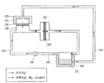
도 2은 냉각 장치(100)를 냉매 및 수소의 흐름이 잘 보이도록 다르게 표현한 것으로, 제2 챔버(120)에는 수소 기체(H2)가 수용되고, 수용된 수소 기체는 전원의 공급으로 이온화되게 된다. 수소 기체의 이온화는 제2 챔버(120)와 접하거나 혹은 맞닿아 있는 촉매부(153)에서 이루어지게 된다. 여기서 전원부(160)는 직류(DC) 전원을 제공하는 것으로, 제2 챔버(120)와 제3 챔버(131)에 연결되어 각각의 챔버에 (+)전원 및 (-)전원을 공급하게 된다.FIG. 2 is a diagram illustrating the
제2 챔버(120)는 전원부(160)로부터 (+)전원을 공급받아 제2 챔버(120)와 접하는 촉매부(153)의 일 측에서 수소 기체의 이온화를 유도하게 된다. (+)전원이 공급되는 제2 챔버(120)에서 수소 기체는 전자를 잃고 양이온이 되므로, 화학적으로 양극(Anode)이라고 할 수 있다.The
제2 챔버(120)와 접하는 촉매부(153)에 의해 수소 기체는 이온화되어 제2 챔버(120)에 수용되고, 수소 이온은 제3 챔버(131)로 이동하게 된다. 수소 이온은 제2 챔버(120) 및 제3 챔버(131) 사이에 개재된 제2 전해질막(151)에 투과되어 제3 챔버(131)로 이동하게 되는데, 수소 이온은 제3 챔버(131)로 이동하면서 제2 챔버(120)에 수용된 기화된 냉매를 함께 이동시키게 된다. 수소 이온은 양이온의 성질을 가지며, 주변에 존재하는 냉매는 극성을 띄므로 함께 이동할 수 있게 된다. 즉, 수소 이온 및 기화된 냉매는 전해질막에 투과되어 제3 챔버(131)로 이동하게 된다. 본 실시예에서는 증발기 챔버와 압축기 챔버가 분리되어 있어 압축기 챔버내의 냉매가 응축되어 액체인 상태로 투과되어도 문제가 되지 않는다.The hydrogen gas is ionized into the
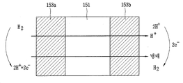
도 3은 수소 이온 및 기화된 냉매가 전해질막에 투과되는 모습을 나타낸다.3 shows a state in which hydrogen ions and a vaporized refrigerant are permeated through the electrolyte membrane.
도 3의 화살표 방향에서 보듯이, 수소는 수소 이온으로 산화되고, 냉매는 수소 이온과 함께 제2 챔버로(120)부터 제3 챔버(131)로 이동하게 된다.3, the hydrogen is oxidized to hydrogen ions, and the refrigerant moves from the
제3 챔버(131)는 연결된 전원부(160)에 의해 (-)전원을 공급받고, 제3 챔버(131)에 수용된 수소 이온은 제3 챔버(131)에 접하는 촉매부(153)에 의해 수소 이온의 환원이 유도된다. 도 3의 우측을 보면, 수소 이온의 환원 과정을 알 수 있는데, 수소 이온은 제3 챔버(131)에서 전자를 얻어 수소 기체로 환원되므로, 화학적으로는 음극(Cathode)이라고 할 수 있다.The
제3 챔버(131)는 응축기(130)의 내부에 위치되고, 응축기(130)는 제3 챔버(131)에 압력을 인가하게 된다. 응축기(130)에 인가된 압력에 의해 제3 챔버(131)에 수용된 기화된 냉매는 액화되어 열을 외부로 방출하게 된다. 이에 제3 챔버(131)에는 액화된 냉매 및 환원된 수소 이온(수소 기체)이 존재하게 된다.The
제3 챔버(131)에서 환원되면서 발생하는 수소 기체는 제3 챔버(131)에 누적되어 압력을 발생시키고, 제3 챔버(131) 및 제2 챔버(120)를 연결하는 제2 배관(142)을 통해 제2 챔버(120)로 이동하게 된다. 수소 기체의 제2 챔버(120)로의 이동은 팽창밸브(145)의 조작을 통해서 용이하게 가능하다. 또한, 제3 챔버(131)에서 액화된 냉매는 수소 기체보다 무거우므로 제3 챔버(131)의 아래쪽에 위치되고, 제3 챔버(131) 및 제1 챔버(111)를 연결하는 제1 배관(141)에 의해 제1 챔버(111)를 향해 이동하게 된다.The hydrogen gas generated by the reduction in the
제1 챔버(111)는 증발기(110) 내부에 위치되고, 제1 챔버(111) 내부에 수용되는 액화된 냉매는 증발기(110)에 연결된 장치로부터 열을 흡수한다. 구체적으로 제3 챔버(131)로부터 전달되어 제1 챔버(111)에 수용된 액화된 냉매는 열을 흡수하여 제1 전해질막(150)을 통과하면서 압력차에 의해 기화된다.The
제1 챔버(111)와 제2 챔버(120) 사이에는 전해질막이 개재되고, 냉매는 전해질막을 통해 제2 챔버(120)로 투과되면서 기화되어 제2 챔버(120)에는 제1 챔버(111)로부터 수용된 기화된 냉매와 제3 챔버(131)로부터 수용된 수소 기체가 존재하게 된다.An electrolyte membrane is interposed between the
그 후, 상기와 같이 제2 챔버(120)에 수용되는 수소 기체(H2)는 전원의 공급으로 제2 챔버(120)와 접하는 촉매부(153)에 의해 이온화되어 기화된 냉매와 함께 제3 챔버(131)로 이동되고, 제3 챔버(131)에 수용된 기화된 냉매는 액화되어 제1 챔버(111)로 이동하며, 제3 챔버에 수용된 수소 이온은 촉매부(153)에 의해 환원되어 제2 챔버(120)로 이동되는 과정이 수행되게 된다.Then, the hydrogen gas H 2 contained in the
이상에서 설명한 도 1의 냉각 장치(100)의 작동 과정은 도 2의 냉각 장치(100)를 다르게 나타내는 개념도를 통해 더욱 상세하게 알 수 있다. 도 2의 냉각 장치(100)는 도 1의 냉각 장치(100)의 작동을 쉽게 알아볼 수 있도록 표현한 것으로, 도 1의 냉각 장치(100)와 동일한 것이다. 도 2에서 수소 및 냉매의 흐름은 화살표를 통해서 나타내었고, 이들의 흐름을 통해서 냉각 장치(100)의 작동을 알 수 있다. 또한, 도 2을 통해서 본 발명인 냉각 장치(100)는 냉매 및 수소가 순환되어 증발기(110)에서 냉매에 의해 흡수되는 열은 압축기에서 응축되어 열을 외부로 방출되는 과정이 반복적으로 수행하게 되는 것을 알 수 있다.The operation of the
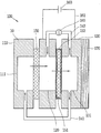
도 4는 도 1의 냉각 장치와 다른 실시예를 나타내는 개념도를 의미하는 것으로, 도 1과 다르게 응축기(130)의 일 측에 열교환기(170)가 결합된다.FIG. 4 is a conceptual diagram illustrating an embodiment different from the cooling apparatus of FIG. 1, in which a
도 4를 참조하면, 냉각 장치(100)의 응축기(130) 일 측에는 제3 챔버(131)에서 냉매가 액화되면서 발생하는 열을 외부로 방출하도록 열교환기(170)가 배치될 수 있다. 열교환기(Heat Exchanger)는 열을 주고받는 장치를 말하며 열의 회수를 목적으로 한다. 열교환기(170)는 스테인리스, 티탄(Ti), 하스테로이, 지르코늄(Zr), 니오브(Nb) 등의 재료로 형성될 수 있다. 본 발명에서 열교환기(170)는 응축기(130)에서 방출되는 열을 흡수하기 위한 것으로 그 형상은 특별히 제한되지 않을 것이다.Referring to FIG. 4, a
상기 기재된 바와 같이, 본 발명에 따르는 냉각 장치(100)는 도 1 및 도 3에서 보듯이 각 챔버와 각 전해질막 및 각 배관이 일체로서 결합되도록 형성될 수 있고, 각 구성이 개별적으로 결합되어 형성될 수도 있을 것이다.As described above, the
이상에서는 도 1 내지 도 4를 통해 수소 기체의 이온화를 이용하는 냉각 장치에 대해 설명하였고, 이하 도 1 내지 도 4와는 다른 냉각 장치의 또 다른 실시예에 대해 설명하겠다.In the foregoing, a cooling apparatus using ionization of hydrogen gas has been described with reference to FIGS. 1 to 4, and another embodiment of the cooling apparatus, which is different from FIGS. 1 to 4, will be described.
도 5는 전기 삼투압 펌프(251)을 포함하는 냉각 장치(200)의 다른 실시예를 나타내는 것으로, 전기 삼투압 펌프(251)를 포함한다. 도 5의 냉각 장치(200)는 도 1 및 도 3의 냉각 장치(100)와 유사한 구성을 가지나, 촉매부(153)에 의한 수소 이온화 과정이 없이 냉매의 순환에 의해 동작되는 구성을 가지므로 촉매부(153)를 포함하지 않는다.FIG. 5 shows another embodiment of a
도 5의 냉각 장치(200)는 증발기(210), 챔버, 응축기(230) 및 전기 삼투압 펌프(251)를 포함하고, 챔버는 제1 챔버(211), 제2 챔버(220), 제3 챔버(231)의 총 3개로 이루어진다. 냉각 장치(200)의 구조에 대해서는 도 1 내지 도 4에서 상세하게 설명하였는바, 이하 도 5의 냉각 장치(200)의 작동 과정을 중심으로 살펴보겠다.5 includes an
도 5의 냉각 장치(200)의 작동에 대해 살펴보면, 증발기(210)는 제1 챔버(211)를 구비하고, 제1 챔버(211)는 액화된 냉매를 제1 배관(241)을 통해 제3 챔버(231)로부터 수용하게 된다. 제1 챔버(211)에 수용되는 액화된 냉매는 외부로부터 열을 흡수하여 기화되게 된다.5, the
제2 챔버(220)는 제1 챔버(211)로부터 전해질막(250)을 통과하면서 기화된 냉매를 전달받아 수용하게 된다. 제1 챔버(211)와 제2 챔버(220) 사이에는 제1 전해질막(250)이 배치되므로 제2 챔버(220)는 제1 챔버(211)로부터 제1 전해질막(250)을 투과한 기화된 냉매를 수용하게 된다.The
응축기(230)는 제2 챔버(220)로부터 기화된 냉매를 전달받고, 기화된 냉매에 압력이 인가되어 액화된 냉매를 수용하는 제3 챔버(231)를 구비하며, 제3 챔버(231)에 수용되는 냉매의 액화에 의해 발생하는 열을 외부로 방출하게 된다.The
도 5의 냉각 장치(200)는 제2 챔버(220) 및 제3 챔버(231) 사이에 전기 삼투압 펌프(251)가 개재되는 구조를 가진다. 이에, 기화된 냉매의 제3 챔버(231)로의 투과는 도 1 및 도 3와는 다르게 제2 전해질막(151)이 아닌 전기 삼투압 펌프(251)에 의해 수행되게 되게 된다.The
전기 삼투압 펌프(electro-osmotic pump, EOP)는 다공성 세라믹 막으로 형성되는 것으로, 다공성 세라믹 막에 존재하는 미세 채널을 통해 기화된 냉매를 이동시킬 수 있다. 전기 삼투압 펌프(251)는 양단에 전압을 걸 때, 유체가 이동하는 현상을 이용한 펌프로서 소음이 없고, 작고 가벼우며, 전기적으로 쉽게 제어 가능한 장점이 있다. The electro-osmotic pump (EOP) is formed of a porous ceramic membrane, and it is possible to move the vaporized refrigerant through the microchannels present in the porous ceramic membrane. The
전기 삼투압 펌프(251)는 수소 이온이 이동하면서 냉매를 수송하는 것이 아닌 전원부(260)에 의해 공급되는 고압 전원을 이용하여 제2 챔버(220)로부터 제3 챔버(231)로 기화된 냉매를 이동시킨다. 구체적으로 전원부(260)는 10V 이상의 직류 전원을 제2 챔버(220) 및 제3 챔버(231)에 인가하게 된다. 즉, 전기 삼투압 펌프(251)는 설정된 전압이 인가되어 기화된 냉매를 제2 챔버(220)로부터 제3 챔버(231)로 투과시킬 수 있다.The
제3 챔버(231)에 수용되는 기화된 냉매는 응축부에 가해진 압력에 의해 응축되게 되고, 액화된 냉매는 제3 챔버(231)의 아래쪽에 위치된다. 다만, 제3 챔버에 인가된 압력에도 액화되지 않고 기화된 상태로 존재하는 냉매는 액화된 냉매보다는 가벼우므로 제3 챔버의 위쪽에 위치하게 된다.The vaporized refrigerant contained in the
제3 챔버에 존재하는 액화된 냉매 및 가해진 압력에도 액화되지 않고 존재하는 기화된 냉매는 제3 챔버와 연결된 배관을 통해 제1 챔버(211) 및 제2 챔버(220)로 각각 분리 이동된다. 액화된 냉매 및 액화되지 않은 냉매를 각각 별도의 챔버로 분리 이동시키면, 액화된 냉매 및 액화되지 않은 냉매를 한번에 전해질막에 투과시키는 것보다 원활한 이동을 도모할 수 있다. 액화된 냉매는 입자가 크기 때문에 전해질막을 투과하기 더 어렵고, 이에 기화된 냉매가 투과되는 것을 방해하기 때문이다. 이에, 도 5에 나타난 바와 같이, 제3 챔버(231)에 연결되는 제1 배관(241) 및 제2 배관(242)을 구현하여 냉매의 원활한 이동을 도모하여 냉각 장치(200)의 효율이 향상될 수 있다.The liquefied refrigerant existing in the third chamber and the vaporized refrigerant that is not liquefied even under the applied pressure are separated and transferred to the
도 5의 냉각 장치(200)에서 제3 챔버(231)에서 액화된 냉매 및 제3 챔버(231)에서 기화된 상태로 잔존하는 냉매를 제1 챔버(211) 및 제2 챔버(220)로 각각 분리 이동되는데, 이는 배관부(241, 242)에 의해 수행된다. 배관부(241, 242)는 제1 배관(241), 제2 배관(242)을 포함한다.The refrigerant liquefied in the
제1 배관(241)은 제1 챔버(211) 및 제2 챔버(220)의 하단을 연결하여 제2 챔버(220)에서 액화된 냉매를 제1 챔버(211)로 수송하는 역할을 한다. 제2 배관(242)은 제2 챔버(220) 및 제3 챔버(231)의 상단을 연결하여 제2 챔버(220)에서 기화된 상태로 잔존하는 냉매를 제3 챔버(231)로 수송하는 역할을 한다. 제2 배관(242)의 일 측에는 팽창밸브(245)가 구비되어 압력이 조절 가능하여 기화된 상태로 잔존하는 냉매의 이동을 제어할 수 있다.The
도 6은 다른 실시예로서 진공 펌프(345)를 포함하는 냉각 장치(300)를 나타낸다. 냉각 장치(300)는 제1 챔버(311)를 포함하는 증발기(310), 제2 챔버(320), 응축기(330) 및 배관부(341)를 포함하는 구성을 가진다.6 shows a
제1 챔버(311)를 구비하는 증발기(310)는 복수 개로 형성될 수 있다. 증발기(310)가 복수 개로 형성되면, 제1 챔버(311)는 증발기(310) 내부에 구비되므로 역시 복수 개로 형성되게 된다. 도 6을 참조하면, 증발기(310)는 제2 챔버(320)의 양쪽에 위치되는 구조를 가지고, 증발기(310)의 내부에 구비된 제1 챔버(311)와 제2 챔버(320)가 서로 마주보는 구조를 가지게 된다.The
제1 챔버(311)에 수용되는 액화된 냉매는 외부의 열을 흡수하여 기화되고, 제1 챔버(311)와 마주보도록 위치되는 제2 챔버(320)를 향해 이동하게 된다. 제1 챔버(311)와 제2 챔버(320)의 사이에는 제1 전해질막(350)이 배치되는데, 제2 챔버(320)는 제1 챔버(311)로부터 제1 전해질막(350)을 투과한 냉매를 전달받아 수용하게 된다. 냉매는 제1 전해질막(350)을 투과하면서 압력변화에 의해 기화한다.The liquefied refrigerant contained in the
제2 챔버(320)는 응축기(330)와 배관을 통해 연결되고, 기화된 냉매는 배관을 통해 제2 챔버(320)로부터 응축기(330)를 향해 이동하게 된다. 여기서 냉매가 이동하는 배관은 제1 배관(341)이라 칭한다.The
제1 챔버(311)로부터 제2 챔버(320)에 수용된 기화된 냉매는 제2 챔버(320)에서 응축기(330)를 향해 제1 배관(341)을 따라 이동하게 된다. 기화된 냉매가 제2 챔버(320)로부터 응축기(330)를 향해 이동될 수 있도록 제2 챔버(320)와 응축기(330)를 연결하는 제1 배관(341)의 일 측에는 진공 펌프(345)가 위치되게 된다.The vaporized refrigerant received in the
진공 펌프(345)는 제2 챔버(320)로부터 기화된 냉매를 응축기(330)를 향해 이동시키는 역할을 하는 것으로, 일정 크기의 용기 내에서 기체를 퍼내 대기압보다 높게 압축하여 배출하는 장치이다. 진공 펌프(345)에는 기계의 왕복, 회전 작용을 이용하는 피스톤 펌프, 회전 펌프가 있다. 즉, 진공 펌프(345)는 기화된 냉매를 제2 챔버(320)로부터 퍼내 응축기(330)를 향해 이동시키는 역할을 하게 된다. 진공 펌프(345)에 의해 도 3의 화살표 방향을 따라 기화된 냉매는 응축기(330)로 유입되게 된다.The
응축기(330)는 진공 펌프(345)의 작동에 의해 제2 챔버(320)로부터 기화된 냉매를 전달받고, 기화된 냉매에 압력을 인가하여 기화된 냉매가 액화되어 외부로 열이 방출되도록 하는 역할을 하게 된다.The
응축기(330)에서 액화된 냉매는 응축기(330)의 아래쪽에 위치하는 제1 배관(341)을 따라 제1 챔버(311)를 향해 이동하게 된다. 액화된 냉매는 자연적으로 아래쪽에 모이게 되고, 그 압력 혹은 아래 방향의 힘에 의해 제1 챔버(311)를 향해 유입되게 된다.The refrigerant liquefied in the
예를 들어, 도 6과 같이 증발기(310)가 제2 챔버(320)를 중심으로 두 개가 설치되는 경우, 응축기(330)에서 액화된 냉매는 응축기(330)로부터 제1 챔버(311)를 연결하는 제1 배관(341)을 따라 제1 챔버(311) 상호간에 연결되어 있는 배관까지 유입되고, 결과적으로 각각의 제1 챔버(311)에 수용되는 결과를 가져온다. 즉, 각각의 제1 챔버(311)에는 응축기(330)로부터 액화된 냉매가 분산되어 유입되는 결과가 생기게 된다. 그 후, 각 제1 챔버(311)에 유입된 액화된 냉매는 열을 흡수하여 기화되게 되고, 제1 전해질막(350)을 거쳐 제2 챔버(320)로 수용되게 된다. 그리고 상기와 같은 과정이 반복되어 수행되게 된다. 결과적으로 냉매는 증발기(310)에서 열을 흡수하여 기화되고, 기화된 냉매는 응축기(330)에서 액화되면서 열을 방출하는 결과를 가져오게 된다. 이때, 제2 챔버(320)에 연결된 진공 펌프(345)를 통해 응축기(330)를 향해 기화된 냉매는 원활히 이동된다.For example, when two
이처럼, 도 6의 냉각 장치(300)는 복수 개의 챔버를 이용하여 냉매를 물리적 상태에 따라 구분하여 순환시킴으로써 냉매의 원활한 순환을 도모하여 냉각 효율을 향상시키는 효과를 가진다.As described above, the
아울러 상기 전기 삼투압 펌프나 진공펌프는 증발기와 응축기 사이의 압력차이를 유도할 수 있도록 제어 되어야 한다.In addition, the electroosmotic pump or the vacuum pump should be controlled to induce a pressure difference between the evaporator and the condenser.
이상에서 설명된 냉각 장치는 상기 설명된 실시예들의 구성과 방법에 한정되는 것이 아니라, 상기 실시예들의 다양한 변형이 이루어질 수 있도록, 각 실시예들의 전부 또는 일부가 선택적으로 조합될 수 있다.The cooling device described above is not limited to the configuration and method of the embodiments described above, but all or some of the embodiments may be selectively combined so that various modifications of the embodiments can be made.
10: 케이스 100, 200, 300: 냉각 장치
110, 210, 310: 증발기 111, 211, 311: 제1 챔버
120, 220, 320: 제2 챔버 130, 230, 330: 응축기
131, 231: 제3 챔버 140: 배관부
141, 241, 341: 제1 배관 142, 242: 제2 배관
145, 245: 팽창밸브 150, 250, 350: 제1 전해질막
151, 251: 제2 전해질막 153: 촉매부
160, 260: 전원부 170: 열교환기
251: 전기 삼투압 펌프 345: 진공 펌프10:
110, 210, 310:
120, 220, 320:
131, 231: Third chamber 140: Piping section
141, 241, 341: first piping 142, 242: second piping
145, 245:
151, 251: Second electrolyte membrane 153:
160, 260: power source unit 170: heat exchanger
251: electroosmotic pump 345: vacuum pump
Claims (19)
상기 제1 챔버로부터 기화된 냉매를 전달받고, 수소 기체가 유입되도록 구성되는 제2 챔버;
상기 제2 챔버를 사이에 두고 상기 제1 챔버와 마주보도록 배치되고, 전원부로부터 공급된 전원에 의해 상기 제2 챔버와 접하는 일 측에서 상기 제2 챔버에 유입된 수소 기체를 이온화시키는 촉매부; 및
상기 제2 챔버로부터 상기 기화된 냉매 및 수소 이온을 전달받고, 상기 기화된 냉매에 압력이 인가되어 액화된 냉매 및 상기 수소 이온이 상기 전원부로부터 전자를 공급받아 환원된 수소 기체를 수용하는 제3 챔버를 구비하며, 상기 냉매의 액화에 의해 외부로 열을 방출시키는 응축기를 포함하고,
상기 제3 챔버에 수용된 액화된 냉매 및 수소 기체는 상기 제1 챔버 및 상기 제2 챔버로 각각 분리 이동되는 것을 특징으로 하는 냉각 장치.An evaporator having a first chamber for receiving liquefied refrigerant and absorbing external heat to vaporize the liquefied refrigerant;
A second chamber configured to receive vaporized refrigerant from the first chamber and to introduce hydrogen gas;
A catalytic part disposed to face the first chamber with the second chamber interposed therebetween and ionizing the hydrogen gas introduced into the second chamber at one side in contact with the second chamber by a power source supplied from a power source part; And
A third chamber for receiving the vaporized refrigerant and hydrogen ions from the second chamber, and a refrigerant liquefied by applying pressure to the vaporized refrigerant, and a third chamber for receiving the reduced hydrogen gas supplied by the hydrogen ions from the power source unit, And a condenser for discharging heat to the outside by liquefaction of the refrigerant,
And the liquefied refrigerant and the hydrogen gas accommodated in the third chamber are separated and moved to the first chamber and the second chamber, respectively.
상기 제3 챔버로부터 상기 액화된 냉매 및 수소 기체가 분리 이동되는 통로를 구비하는 배관부를 더 포함하고,
상기 배관부는,
상기 제1 챔버 및 상기 제3 챔버의 하부를 연결하여 상기 제3 챔버에서 액화된 냉매를 상기 제1 챔버로 수송하는 제1 배관; 및
상기 제2 챔버 및 상기 제3 챔버의 상부를 연결하여 상기 제3 챔버에서 환원된 수소 기체를 상기 제2 챔버로 수송하는 제2 배관을 포함하는 것을 특징으로 하는 냉각 장치.The method according to claim 1,
Further comprising a piping section having a passage through which the liquefied refrigerant and the hydrogen gas are separated from the third chamber,
Wherein,
A first pipe connecting the first chamber and the lower portion of the third chamber to transport the refrigerant liquefied in the third chamber to the first chamber; And
And a second pipe connecting the second chamber and an upper portion of the third chamber to transport hydrogen gas reduced in the third chamber to the second chamber.
상기 제2 배관의 일 측에 설치되고, 상기 제2 배관 내의 압력을 조절하여 상기 수소 기체의 이동을 제어하는 팽창밸브를 더 포함하는 것을 특징으로 하는 냉각 장치.3. The method of claim 2,
Further comprising an expansion valve provided at one side of the second pipe for controlling the movement of the hydrogen gas by controlling a pressure in the second pipe.
상기 제1 챔버 및 상기 제2 챔버 사이에 개재되어 상기 증발기에 의해 기화된 냉매를 상기 제1 챔버로부터 제2 챔버로 투과되도록 하는 제1 전해질막을 더 포함하는 것을 특징으로 하는 냉각 장치.The method according to claim 1,
Further comprising a first electrolyte membrane interposed between the first chamber and the second chamber to allow refrigerant vaporized by the evaporator to pass from the first chamber to the second chamber.
상기 제2 챔버 및 상기 제3 챔버 사이에 개재되어 상기 기화된 냉매 및 수소 이온을 상기 제2 챔버로부터 상기 제3 챔버로 투과되도록 하는 제2 전해질막을 더 포함하는 것을 특징으로 하는 냉각 장치.The method according to claim 1,
And a second electrolyte film interposed between the second chamber and the third chamber to allow the vaporized refrigerant and hydrogen ions to be transmitted from the second chamber to the third chamber.
상기 제2 전해질막은 상기 촉매부에 의해 형성되는 수소 이온이 이동 가능하도록 양성자 전도 전해질막으로 이루어지는 것을 특징으로 하는 냉각 장치.6. The method of claim 5,
Wherein the second electrolyte membrane is made of a proton conducting electrolyte membrane so that hydrogen ions formed by the catalyst unit can move.
상기 촉매부는 상기 제2 전해질막의 외측에 형성되고, 상기 제2 챔버 및 상기 제3 챔버의 사이에 위치되는 것을 특징으로 하는 냉각 장치.6. The method of claim 5,
Wherein the catalyst portion is formed outside the second electrolyte film, and is located between the second chamber and the third chamber.
상기 촉매부는 상기 제2 챔버와 접하는 일 측에서 상기 제2 챔버 내의 상기 수소 기체의 산화를 유도하고, 상기 제3 챔버와 접하는 타 측에서 상기 제3 챔버 내의 상기 수소 이온의 환원을 유도하는 것을 특징으로 하는 냉각 장치.8. The method of claim 7,
The catalytic portion induces oxidation of the hydrogen gas in the second chamber at one side in contact with the second chamber and induces reduction of the hydrogen ion in the third chamber at the other side in contact with the third chamber .
상기 증발기는 제2 챔버와 마주보도록 배치되는 것을 특징으로 하는 냉각 장치.The method according to claim 1,
Wherein the evaporator is arranged to face the second chamber.
상기 냉매는 수용성 용매로서 물(H2O), 알코올(alcohol) 및 암모니아(NH3) 중 적어도 어느 하나인 것을 특징으로 하는 냉각 장치.The method according to claim 1,
Wherein the refrigerant is at least one of water (H 2 O), alcohol and ammonia (NH 3 ) as an aqueous solvent.
상기 전원부는,
상기 제2 챔버에 수용된 수소 기체는 산화되고 상기 제3 챔버에 수용된 수소 이온은 환원되도록, 상기 제2 챔버 및 상기 제3 챔버에 각각 (+)극 및 (-)극이 연결되며, 기설정된 전압을 공급하여 상기 냉매의 전기 분해를 방지하는 것을 특징으로 하는 냉각 장치.The method according to claim 1,
The power supply unit,
(+) And (-) poles are connected to the second chamber and the third chamber so that the hydrogen gas contained in the second chamber is oxidized and the hydrogen ions contained in the third chamber are reduced, So as to prevent the refrigerant from being electrolyzed.
상기 제3 챔버에서 상기 냉매가 액화되면서 발생하는 열이 외부로 방출되도록 상기 응축기의 일 측에 구비되는 열교환기를 더 포함하는 것을 특징으로 하는 냉각 장치.The method according to claim 1,
Further comprising a heat exchanger provided on one side of the condenser so that heat generated when the refrigerant is liquefied in the third chamber is discharged to the outside.
상기 제1 챔버로부터 기화된 냉매를 전달받아 수용하는 제2 챔버;
상기 제2 챔버로부터 기화된 냉매를 전달받고, 상기 기화된 냉매에 압력이 인가되어 액화된 냉매를 수용하는 제3 챔버를 구비하며, 상기 냉매의 액화에 의해 외부로 열을 방출시키는 응축기; 및
상기 제2 챔버 및 상기 제3 챔버 사이에 개재되어 설정된 전압의 인가로 상기 기화된 냉매를 상기 제2 챔버로부터 상기 제3 챔버로 투과시키는 전기 삼투압 펌프를 포함하고,
상기 제3 챔버에서 액화된 냉매 및 상기 제3 챔버에서 기화된 상태로 잔존하는 냉매는 상기 제1 챔버 및 상기 제2 챔버로 각각 분리 이동되는 것을 특징으로 하는 냉각 장치.An evaporator having a first chamber for receiving liquefied refrigerant and absorbing external heat to vaporize the liquefied refrigerant;
A second chamber for receiving and receiving the vaporized refrigerant from the first chamber;
And a third chamber receiving the vaporized refrigerant from the second chamber and receiving the liquefied refrigerant by applying pressure to the vaporized refrigerant, wherein the condenser discharges heat to the outside by liquefying the refrigerant; And
And an electroosmotic pump for passing the vaporized refrigerant from the second chamber to the third chamber by application of a voltage interposed between the second chamber and the third chamber,
Wherein the refrigerant liquefied in the third chamber and the refrigerant remaining in the vaporized state in the third chamber are separated and moved to the first chamber and the second chamber, respectively.
상기 제1 챔버 및 상기 제2 챔버 사이에 개재되어 상기 증발기에 의해 기화된 냉매를 상기 제1 챔버로부터 제2 챔버로 투과되도록 하는 제1 전해질막을 더 포함하는 것을 특징으로 하는 냉각 장치.14. The method of claim 13,
Further comprising a first electrolyte membrane interposed between the first chamber and the second chamber to allow refrigerant vaporized by the evaporator to pass from the first chamber to the second chamber.
상기 전기 삼투압 펌프는 다공성 세라믹 막으로 형성되고, 상기 다공성 세라믹 막에 존재하는 미세 채널을 통해 상기 기화된 냉매가 이동되도록 하는 것을 특징으로 하는 냉각 장치.14. The method of claim 13,
Wherein the electroosmotic pump is formed of a porous ceramic membrane, and the vaporized refrigerant is moved through fine channels existing in the porous ceramic membrane.
상기 제2 챔버로부터 상기 액화된 냉매 및 기화된 냉매를 각각 분리 이동시키는 통로를 구비하는 배관부를 더 포함하고,
상기 배관부는,
상기 제1 챔버 및 상기 제2 챔버의 하단을 연결하여 상기 제2 챔버에서 액화된 냉매를 상기 제1 챔버로 수송하는 제1 배관; 및
상기 제2 챔버 및 상기 제3 챔버의 상단을 연결하여 상기 제2 챔버에서 기화된 상태로 잔존하는 냉매를 상기 제3 챔버로 수송하는 제2 배관을 포함하는 것을 특징으로 하는 냉각 장치.14. The method of claim 13,
Further comprising a piping section having a passage for separating and moving the liquefied refrigerant and the vaporized refrigerant from the second chamber, respectively,
Wherein,
A first pipe connecting the first chamber and the lower end of the second chamber to transport refrigerant liquefied in the second chamber to the first chamber; And
And a second pipe connecting the upper ends of the second chamber and the third chamber to transport the remaining refrigerant vaporized in the second chamber to the third chamber.
상기 제2 배관은 일 측에 연결되는 팽창밸브를 통해 압력이 조절되어 상기 기화된 상태로 잔존하는 냉매의 이동을 제어하는 것을 특징으로 하는 냉각 장치.17. The method of claim 16,
And the second piping is controlled in pressure through an expansion valve connected to one side to control the movement of the refrigerant remaining in the vaporized state.
상기 제1 챔버와 제1 전해질막을 사이에 두고 위치되어 상기 제1 전해질막을 거쳐 상기 제1 챔버로부터 기화된 냉매를 전달받는 제2 챔버; 및
진공 펌프의 작동에 의해 상기 제2 챔버로부터 기화된 냉매를 전달받고, 상기 기화된 냉매에 압력이 인가되어 상기 기화된 냉매가 액화되어 외부로 열이 방출되도록 하는 응축기를 포함하며,
상기 응축기에서 액화된 냉매는 상기 복수 개의 증발기에 구비되는 상기 제1 챔버들로 각각 이동되는 것을 특징으로 하는 냉각 장치.A plurality of evaporators having a first chamber for accommodating liquefied refrigerant and absorbing external heat to vaporize the liquefied refrigerant;
A second chamber positioned between the first chamber and the first electrolyte membrane and receiving vaporized refrigerant from the first chamber through the first electrolyte membrane; And
And a condenser for receiving the vaporized refrigerant from the second chamber by operation of the vacuum pump and applying pressure to the vaporized refrigerant to cause the vaporized refrigerant to be liquefied to discharge heat to the outside,
And the refrigerant liquefied in the condenser is respectively transferred to the first chambers provided in the plurality of evaporators.
상기 진공 펌프는 상기 제2 챔버 및 상기 응축기를 연결하는 배관의 일 측에 위치되어 기화된 냉매를 상기 제2 챔버로부터 방출시키는 것을 특징으로 하는 냉각 장치.19. The method of claim 18,
Wherein the vacuum pump is located at one side of a pipe connecting the second chamber and the condenser to discharge the vaporized refrigerant from the second chamber.
Priority Applications (1)
| Application Number | Priority Date | Filing Date | Title |
|---|---|---|---|
| KR1020150142953A KR102364086B1 (en) | 2015-10-13 | 2015-10-13 | Cooling apparatus using electrochemical reaction |
Applications Claiming Priority (1)
| Application Number | Priority Date | Filing Date | Title |
|---|---|---|---|
| KR1020150142953A KR102364086B1 (en) | 2015-10-13 | 2015-10-13 | Cooling apparatus using electrochemical reaction |
Publications (2)
| Publication Number | Publication Date |
|---|---|
| KR20170043331A true KR20170043331A (en) | 2017-04-21 |
| KR102364086B1 KR102364086B1 (en) | 2022-02-17 |
Family
ID=58705497
Family Applications (1)
| Application Number | Title | Priority Date | Filing Date |
|---|---|---|---|
| KR1020150142953A KR102364086B1 (en) | 2015-10-13 | 2015-10-13 | Cooling apparatus using electrochemical reaction |
Country Status (1)
| Country | Link |
|---|---|
| KR (1) | KR102364086B1 (en) |
Cited By (2)
| Publication number | Priority date | Publication date | Assignee | Title |
|---|---|---|---|---|
| KR102118871B1 (en) * | 2018-11-28 | 2020-06-04 | 한국에너지기술연구원 | Heat pump system by electro-osmosis |
| WO2020248003A1 (en) * | 2019-06-13 | 2020-12-17 | Noh5 Cooling Pty. Ltd. | Vacuum cooling system and method |
Citations (9)
| Publication number | Priority date | Publication date | Assignee | Title |
|---|---|---|---|---|
| JP2003262424A (en) * | 2002-03-08 | 2003-09-19 | Sekisui Chem Co Ltd | Heat pump |
| JP2003262423A (en) * | 2002-03-08 | 2003-09-19 | Sekisui Chem Co Ltd | Heat pump |
| US20050117300A1 (en) * | 2003-03-31 | 2005-06-02 | Ravi Prasher | Channeled heat sink and chassis with integrated heat rejecter for two-phase cooling |
| KR20130085839A (en) * | 2012-01-20 | 2013-07-30 | 지에스파워주식회사 | Heating and cooling system using heat from fuel cell |
| KR20130120082A (en) * | 2012-04-25 | 2013-11-04 | 한국수력원자력 주식회사 | Hydrogen storage vessel capable of control simultaneously exothermic and endothermic |
| KR20140031241A (en) * | 2011-03-30 | 2014-03-12 | 알스톰 테크놀러지 리미티드 | Cryogenic co?? separation using a refrigeration system |
| KR20140059749A (en) * | 2012-11-08 | 2014-05-16 | 가부시끼가이샤 도시바 | Apparatus for reducing oxygen and refrigerator |
| KR20150007554A (en) * | 2013-07-11 | 2015-01-21 | 유니셈(주) | Method for controlling temperature in chiller device |
| JP5681978B2 (en) * | 2013-01-24 | 2015-03-11 | パナソニックIpマネジメント株式会社 | Heat pump equipment |
-
2015
- 2015-10-13 KR KR1020150142953A patent/KR102364086B1/en active IP Right Grant
Patent Citations (9)
| Publication number | Priority date | Publication date | Assignee | Title |
|---|---|---|---|---|
| JP2003262424A (en) * | 2002-03-08 | 2003-09-19 | Sekisui Chem Co Ltd | Heat pump |
| JP2003262423A (en) * | 2002-03-08 | 2003-09-19 | Sekisui Chem Co Ltd | Heat pump |
| US20050117300A1 (en) * | 2003-03-31 | 2005-06-02 | Ravi Prasher | Channeled heat sink and chassis with integrated heat rejecter for two-phase cooling |
| KR20140031241A (en) * | 2011-03-30 | 2014-03-12 | 알스톰 테크놀러지 리미티드 | Cryogenic co?? separation using a refrigeration system |
| KR20130085839A (en) * | 2012-01-20 | 2013-07-30 | 지에스파워주식회사 | Heating and cooling system using heat from fuel cell |
| KR20130120082A (en) * | 2012-04-25 | 2013-11-04 | 한국수력원자력 주식회사 | Hydrogen storage vessel capable of control simultaneously exothermic and endothermic |
| KR20140059749A (en) * | 2012-11-08 | 2014-05-16 | 가부시끼가이샤 도시바 | Apparatus for reducing oxygen and refrigerator |
| JP5681978B2 (en) * | 2013-01-24 | 2015-03-11 | パナソニックIpマネジメント株式会社 | Heat pump equipment |
| KR20150007554A (en) * | 2013-07-11 | 2015-01-21 | 유니셈(주) | Method for controlling temperature in chiller device |
Cited By (2)
| Publication number | Priority date | Publication date | Assignee | Title |
|---|---|---|---|---|
| KR102118871B1 (en) * | 2018-11-28 | 2020-06-04 | 한국에너지기술연구원 | Heat pump system by electro-osmosis |
| WO2020248003A1 (en) * | 2019-06-13 | 2020-12-17 | Noh5 Cooling Pty. Ltd. | Vacuum cooling system and method |
Also Published As
| Publication number | Publication date |
|---|---|
| KR102364086B1 (en) | 2022-02-17 |
Similar Documents
| Publication | Publication Date | Title |
|---|---|---|
| JP5681978B2 (en) | Heat pump equipment | |
| JP6371413B2 (en) | Electrolysis system | |
| KR102591724B1 (en) | Electrodialysis system used to remove solvent from fluid and non-fluid flows | |
| US8769972B2 (en) | Electrochemical compressor and refrigeration system | |
| US7488421B2 (en) | Method and device for the purification, especially desalination, of water | |
| US11015875B2 (en) | Electrochemical heat pump | |
| CN105186026A (en) | Biopolar Plate For Fuel Cell Or Electrolysis | |
| WO2015147142A1 (en) | Water-electrolysis method and water-electrolysis device | |
| KR20170043331A (en) | Cooling apparatus using electrochemical reaction | |
| US20160195306A1 (en) | Electrochemical refrigeration systems and appliances | |
| JP3080865B2 (en) | Hydrogen / oxygen generator | |
| JP6348143B2 (en) | Depressurization method for high pressure water electrolysis system | |
| US9574796B2 (en) | Electrochemical refrigeration systems and appliances | |
| KR20200060146A (en) | Electrolysis system | |
| US11710845B2 (en) | Systems, devices, and methods employing electrochemical processing with oxygen as carrier gas | |
| JP2011168862A (en) | Water electrolysis system and method for operating the same | |
| JP2006510186A (en) | Electrochemical power generator and method of using the same | |
| JP5415168B2 (en) | Water electrolysis system | |
| US20160195307A1 (en) | Electrochemical refrigeration systems and appliances | |
| JP5421876B2 (en) | Water electrolysis system and depressurization method thereof | |
| JP2003262424A (en) | Heat pump | |
| JP2019102170A (en) | Cooling apparatus | |
| JP2003262423A (en) | Heat pump | |
| US20160195305A1 (en) | Electrochemical refrigeration systems and appliances | |
| JP4159220B2 (en) | Absorption refrigerator hydrogen gas removal device |
Legal Events
| Date | Code | Title | Description |
|---|---|---|---|
| E701 | Decision to grant or registration of patent right | ||
| GRNT | Written decision to grant |