KR20170040919A - Battery Module Having Prove for Sensing Expansion of Battery Cell - Google Patents
Battery Module Having Prove for Sensing Expansion of Battery Cell Download PDFInfo
- Publication number
- KR20170040919A KR20170040919A KR1020150140182A KR20150140182A KR20170040919A KR 20170040919 A KR20170040919 A KR 20170040919A KR 1020150140182 A KR1020150140182 A KR 1020150140182A KR 20150140182 A KR20150140182 A KR 20150140182A KR 20170040919 A KR20170040919 A KR 20170040919A
- Authority
- KR
- South Korea
- Prior art keywords
- battery
- battery module
- electrode assembly
- case
- battery cell
- Prior art date
Links
- 239000000523 sample Substances 0.000 claims abstract description 37
- 230000008859 change Effects 0.000 claims abstract description 4
- 230000002093 peripheral effect Effects 0.000 claims description 6
- 238000007789 sealing Methods 0.000 claims description 6
- 229910052751 metal Inorganic materials 0.000 claims description 5
- 239000002184 metal Substances 0.000 claims description 5
- 239000011347 resin Substances 0.000 claims description 5
- 229920005989 resin Polymers 0.000 claims description 5
- 238000007599 discharging Methods 0.000 claims description 3
- 230000004927 fusion Effects 0.000 claims description 3
- 238000012544 monitoring process Methods 0.000 claims description 2
- HBBGRARXTFLTSG-UHFFFAOYSA-N Lithium ion Chemical compound [Li+] HBBGRARXTFLTSG-UHFFFAOYSA-N 0.000 description 3
- 229910001416 lithium ion Inorganic materials 0.000 description 3
- 229920000642 polymer Polymers 0.000 description 3
- 238000004519 manufacturing process Methods 0.000 description 2
- 239000000463 material Substances 0.000 description 2
- 238000000034 method Methods 0.000 description 2
- WHXSMMKQMYFTQS-UHFFFAOYSA-N Lithium Chemical compound [Li] WHXSMMKQMYFTQS-UHFFFAOYSA-N 0.000 description 1
- 238000007792 addition Methods 0.000 description 1
- 238000003915 air pollution Methods 0.000 description 1
- 229910052782 aluminium Inorganic materials 0.000 description 1
- XAGFODPZIPBFFR-UHFFFAOYSA-N aluminium Chemical compound [Al] XAGFODPZIPBFFR-UHFFFAOYSA-N 0.000 description 1
- 230000004888 barrier function Effects 0.000 description 1
- 230000000694 effects Effects 0.000 description 1
- 239000003792 electrolyte Substances 0.000 description 1
- 239000008151 electrolyte solution Substances 0.000 description 1
- 238000004880 explosion Methods 0.000 description 1
- 239000002803 fossil fuel Substances 0.000 description 1
- 238000009413 insulation Methods 0.000 description 1
- 229910052744 lithium Inorganic materials 0.000 description 1
- 230000007257 malfunction Effects 0.000 description 1
- 238000012986 modification Methods 0.000 description 1
- 230000004048 modification Effects 0.000 description 1
- 230000035515 penetration Effects 0.000 description 1
- 230000008569 process Effects 0.000 description 1
- 239000000243 solution Substances 0.000 description 1
- 238000006467 substitution reaction Methods 0.000 description 1
Images


Classifications
-
- H—ELECTRICITY
- H01—ELECTRIC ELEMENTS
- H01M—PROCESSES OR MEANS, e.g. BATTERIES, FOR THE DIRECT CONVERSION OF CHEMICAL ENERGY INTO ELECTRICAL ENERGY
- H01M10/00—Secondary cells; Manufacture thereof
- H01M10/42—Methods or arrangements for servicing or maintenance of secondary cells or secondary half-cells
- H01M10/48—Accumulators combined with arrangements for measuring, testing or indicating the condition of cells, e.g. the level or density of the electrolyte
-
- H—ELECTRICITY
- H01—ELECTRIC ELEMENTS
- H01M—PROCESSES OR MEANS, e.g. BATTERIES, FOR THE DIRECT CONVERSION OF CHEMICAL ENERGY INTO ELECTRICAL ENERGY
- H01M10/00—Secondary cells; Manufacture thereof
- H01M10/42—Methods or arrangements for servicing or maintenance of secondary cells or secondary half-cells
- H01M10/425—Structural combination with electronic components, e.g. electronic circuits integrated to the outside of the casing
-
- H—ELECTRICITY
- H01—ELECTRIC ELEMENTS
- H01M—PROCESSES OR MEANS, e.g. BATTERIES, FOR THE DIRECT CONVERSION OF CHEMICAL ENERGY INTO ELECTRICAL ENERGY
- H01M10/00—Secondary cells; Manufacture thereof
- H01M10/42—Methods or arrangements for servicing or maintenance of secondary cells or secondary half-cells
- H01M10/48—Accumulators combined with arrangements for measuring, testing or indicating the condition of cells, e.g. the level or density of the electrolyte
- H01M10/482—Accumulators combined with arrangements for measuring, testing or indicating the condition of cells, e.g. the level or density of the electrolyte for several batteries or cells simultaneously or sequentially
-
- H01M2/0287—
-
- H01M2/1083—
-
- H01M2/34—
-
- H—ELECTRICITY
- H01—ELECTRIC ELEMENTS
- H01M—PROCESSES OR MEANS, e.g. BATTERIES, FOR THE DIRECT CONVERSION OF CHEMICAL ENERGY INTO ELECTRICAL ENERGY
- H01M50/00—Constructional details or processes of manufacture of the non-active parts of electrochemical cells other than fuel cells, e.g. hybrid cells
- H01M50/10—Primary casings; Jackets or wrappings
- H01M50/102—Primary casings; Jackets or wrappings characterised by their shape or physical structure
- H01M50/105—Pouches or flexible bags
-
- H—ELECTRICITY
- H01—ELECTRIC ELEMENTS
- H01M—PROCESSES OR MEANS, e.g. BATTERIES, FOR THE DIRECT CONVERSION OF CHEMICAL ENERGY INTO ELECTRICAL ENERGY
- H01M50/00—Constructional details or processes of manufacture of the non-active parts of electrochemical cells other than fuel cells, e.g. hybrid cells
- H01M50/10—Primary casings; Jackets or wrappings
- H01M50/116—Primary casings; Jackets or wrappings characterised by the material
- H01M50/124—Primary casings; Jackets or wrappings characterised by the material having a layered structure
-
- H—ELECTRICITY
- H01—ELECTRIC ELEMENTS
- H01M—PROCESSES OR MEANS, e.g. BATTERIES, FOR THE DIRECT CONVERSION OF CHEMICAL ENERGY INTO ELECTRICAL ENERGY
- H01M50/00—Constructional details or processes of manufacture of the non-active parts of electrochemical cells other than fuel cells, e.g. hybrid cells
- H01M50/20—Mountings; Secondary casings or frames; Racks, modules or packs; Suspension devices; Shock absorbers; Transport or carrying devices; Holders
- H01M50/204—Racks, modules or packs for multiple batteries or multiple cells
- H01M50/207—Racks, modules or packs for multiple batteries or multiple cells characterised by their shape
- H01M50/211—Racks, modules or packs for multiple batteries or multiple cells characterised by their shape adapted for pouch cells
-
- H—ELECTRICITY
- H01—ELECTRIC ELEMENTS
- H01M—PROCESSES OR MEANS, e.g. BATTERIES, FOR THE DIRECT CONVERSION OF CHEMICAL ENERGY INTO ELECTRICAL ENERGY
- H01M50/00—Constructional details or processes of manufacture of the non-active parts of electrochemical cells other than fuel cells, e.g. hybrid cells
- H01M50/50—Current conducting connections for cells or batteries
- H01M50/569—Constructional details of current conducting connections for detecting conditions inside cells or batteries, e.g. details of voltage sensing terminals
-
- H—ELECTRICITY
- H01—ELECTRIC ELEMENTS
- H01M—PROCESSES OR MEANS, e.g. BATTERIES, FOR THE DIRECT CONVERSION OF CHEMICAL ENERGY INTO ELECTRICAL ENERGY
- H01M50/00—Constructional details or processes of manufacture of the non-active parts of electrochemical cells other than fuel cells, e.g. hybrid cells
- H01M50/50—Current conducting connections for cells or batteries
- H01M50/572—Means for preventing undesired use or discharge
- H01M50/574—Devices or arrangements for the interruption of current
- H01M50/578—Devices or arrangements for the interruption of current in response to pressure
-
- H—ELECTRICITY
- H01—ELECTRIC ELEMENTS
- H01M—PROCESSES OR MEANS, e.g. BATTERIES, FOR THE DIRECT CONVERSION OF CHEMICAL ENERGY INTO ELECTRICAL ENERGY
- H01M2200/00—Safety devices for primary or secondary batteries
- H01M2200/20—Pressure-sensitive devices
-
- H—ELECTRICITY
- H01—ELECTRIC ELEMENTS
- H01M—PROCESSES OR MEANS, e.g. BATTERIES, FOR THE DIRECT CONVERSION OF CHEMICAL ENERGY INTO ELECTRICAL ENERGY
- H01M2220/00—Batteries for particular applications
- H01M2220/20—Batteries in motive systems, e.g. vehicle, ship, plane
-
- Y—GENERAL TAGGING OF NEW TECHNOLOGICAL DEVELOPMENTS; GENERAL TAGGING OF CROSS-SECTIONAL TECHNOLOGIES SPANNING OVER SEVERAL SECTIONS OF THE IPC; TECHNICAL SUBJECTS COVERED BY FORMER USPC CROSS-REFERENCE ART COLLECTIONS [XRACs] AND DIGESTS
- Y02—TECHNOLOGIES OR APPLICATIONS FOR MITIGATION OR ADAPTATION AGAINST CLIMATE CHANGE
- Y02E—REDUCTION OF GREENHOUSE GAS [GHG] EMISSIONS, RELATED TO ENERGY GENERATION, TRANSMISSION OR DISTRIBUTION
- Y02E60/00—Enabling technologies; Technologies with a potential or indirect contribution to GHG emissions mitigation
- Y02E60/10—Energy storage using batteries
-
- Y02E60/122—
Landscapes
- Chemical & Material Sciences (AREA)
- Chemical Kinetics & Catalysis (AREA)
- Electrochemistry (AREA)
- General Chemical & Material Sciences (AREA)
- Engineering & Computer Science (AREA)
- Manufacturing & Machinery (AREA)
- Microelectronics & Electronic Packaging (AREA)
- Sealing Battery Cases Or Jackets (AREA)
- Secondary Cells (AREA)
- Battery Mounting, Suspending (AREA)
Abstract
Description
본 발명은 전지셀의 팽창을 감지하기 위한 프로브를 포함하고 있는 전지모듈에 관한 것이다.The present invention relates to a battery module including a probe for detecting the expansion of a battery cell.
최근, 충방전이 가능한 이차전지는 와이어리스 모바일 기기의 에너지원으로 광범위하게 사용되고 있다. 또한, 이차전지는, 화석 연료를 사용하는 기존의 가솔린 차량, 디젤 차량 등의 대기오염 등을 해결하기 위한 방안으로 제시되고 있는 전기자동차, 하이브리드 전기자동차 등의 에너지원으로서도 주목받고 있다. 따라서, 이차전지를 사용하는 애플리케이션의 종류는 이차전지의 장점으로 인해 매우 다양화되고 있으며, 향후에는 지금보다는 많은 분야와 제품들에 이차전지가 적용될 것으로 예상된다.BACKGROUND ART [0002] In recent years, rechargeable secondary batteries have been widely used as energy sources for wireless mobile devices. In addition, the secondary battery is attracting attention as an energy source for electric vehicles, hybrid electric vehicles, and the like, which is proposed as a solution for air pollution in existing gasoline vehicles and diesel vehicles using fossil fuels. Therefore, the types of applications using secondary batteries are diversifying due to the advantages of secondary batteries, and it is expected that secondary batteries will be applied to many fields and products in the future.
이러한 이차전지는 전극과 전해액의 구성에 따라 리튬이온 전지, 리튬이온 폴리머 전지, 리튬 폴리머 전지 등으로 분류되기도 하며, 그 중 전해액의 누액 가능성이 적으며, 제조가 용이한 리튬이온 폴리머 전지의 사용량이 늘어나고 있다. 일반적으로, 이차전지는 전지케이스의 형상에 따라, 전극조립체가 원통형 또는 각형의 금속 캔에 내장되어 있는 원통형 전지 및 각형 전지와, 전극조립체가 알루미늄 라미네이트 시트의 파우치형 케이스에 내장되어 있는 파우치형 전지로 분류된다.Such a secondary battery may be classified as a lithium ion battery, a lithium ion polymer battery, or a lithium polymer battery depending on the configuration of an electrode and an electrolytic solution. The amount of the lithium ion polymer battery Is growing. 2. Description of the Related Art Generally, a secondary battery includes a cylindrical battery and a prismatic battery in which an electrode assembly is embedded in a cylindrical or rectangular metal can according to the shape of a battery case, and a pouch type battery in which an electrode assembly is embedded in a pouch- .
이 중, 전지의 고용량화로 인해 케이스의 대면적화 및 얇은 소재로의 가공이 많은 관심을 모으고 있고, 이에 따라, 스택형 또는 스택/폴딩형 전극조립체를 알루미늄 라미네이트 시트의 파우치형 전지케이스에 내장한 구조의 파우치형 전지가, 낮은 제조비, 작은 중량, 용이한 형태 변형 등을 이유로, 사용량이 점차적으로 증가하고 있다.Among them, due to the high capacity of the battery, enlargement of the size of the case and the processing of a thin material are attracting much attention. Accordingly, a stacked or stacked / folded type electrode assembly is embedded in a pouch-shaped battery case of an aluminum laminate sheet The pouch-shaped battery of the present invention has been gradually increased in usage due to low manufacturing cost, small weight, and easy shape deformation.
도 1에는 종래의 파우치형 전지의 모식도가 도시되어 있다.1 is a schematic view of a conventional pouch-type battery.
도 1을 참조하면, 파우치형 이차전지(10)는, 파우치형 전지케이스(20) 내부에, 양극, 음극 및 이들 사이에 배치되는 분리막으로 이루어진 전극조립체(30)가 그것의 양극 및 음극 탭들(31, 32)과 전기적으로 연결되는 두 개의 전극리드들(40, 41)이 외부로 노출되도록 밀봉되어 있는 구조로 이루어져 있다.Referring to FIG. 1, the pouch type
전지케이스(20)는 전극조립체(30)가 안착될 수 있는 오목한 형상의 수납부(23)를 포함하는 케이스 본체(21)와 그러한 본체(21)에 일체로서 연결되어 있는 커버(22)로 이루어져 있다.The
스택형 전극조립체(30)는 다수의 양극 탭들(31)과 다수의 음극 탭들(32)이 각각 융착되어 전극리드(40, 41)에 함께 결합되어 있다. 또한, 케이스 본체(21)의 상단부(24)와 커버(22)의 상단부에는 전극리드(40, 41)가 위치하고 쇼트 발생을 방지하기 위해 절연필름(50)이 부착되어 있다.In the stacked
이러한 파우치형 이차전지는 각종 모바일 기기는 물론 다양한 전자제품의 에너지원으로 널리 사용되고 있지만, 충방전 과정에서 내부에서 가스가 발생하는 경우에 전지케이스가 파단되어 유해 가스가 유출되고 이는 사용자의 건강상 안전에 위협이 될 수 있으며 추가적인 전지 오작동으로 예상치 못한 발열, 폭발 등의 위험성이 있다.Such a pouch-type secondary battery is widely used as an energy source for various electronic devices as well as various mobile devices. However, when gas is generated in the charging / discharging process, the battery case is broken and harmful gas is leaked. Which may lead to unexpected heat or explosion due to malfunction of the battery.
이차전지 및 이를 포함하는 중대형 전지모듈에는 과충전, 과방전, 과전류시 전류를 차단하는 보호회로, 퓨즈 등의 안전 장치들이 구비되어 있지만 전지 내부 가스 발생량을 실시간으로 검출하지 못하며, 이에 따라 전지케이스의 파단 시점을 판단하지 못하여 안전성이 크게 저하되어 소망하는 효과를 발휘하기 어려운 문제점이 있다.The secondary battery and the middle- or large-sized battery module including the secondary battery are provided with safety devices such as a protection circuit and a fuse for shutting off current during overcharging, overdischarge, and overcurrent, but the amount of gas generated in the battery can not be detected in real time, The time is not judged, and the safety is significantly lowered, so that it is difficult to exhibit a desired effect.
본 발명은 상기와 같은 종래기술의 문제점과 과거로부터 요청되어온 기술적 과제를 해결하는 것을 목적으로 한다.SUMMARY OF THE INVENTION It is an object of the present invention to solve the above-mentioned problems of the prior art and the technical problems required from the past.
구체적으로, 본 발명의 목적은 이차전지의 내부 압력을 검출하여 전지케이스가 파단 되기 전에 경고 신호를 전송하여 사고를 사전에 예방하기 위한 것으로, 전지모듈을 구성하고 있는 이차전지의 전지셀의 외면에 설치되어, 전지셀의 국부적인 부피 팽창 변화를 감지하여 신호를 송신하고, 신호에 의한 내부 압력이 임계 압력값 이상일 때 전지모듈의 안전성 확보를 위한 경고 신호를 생성하는 전지모듈을 제공하는 것이다.More particularly, the present invention relates to a method for detecting an internal pressure of a secondary battery and transmitting an alarm signal to the battery cell before the battery cell breaks, And a battery module for generating a warning signal for securing the safety of the battery module when the internal pressure of the signal exceeds a critical pressure value.
이러한 목적을 달성하기 위한 본 발명에 따른 전지셀의 팽창을 감지하기 위한 프로브를 포함하고 있는 전지모듈은,In order to accomplish the above object, according to the present invention, there is provided a battery module including a probe for detecting expansion of a battery cell,
충방전이 가능한 둘 이상의 전지셀들을 포함하고 있는 전지모듈로서,A battery module comprising at least two battery cells capable of charging and discharging,
상기 전지셀들 중의 적어도 하나의 전지셀의 외면에 설치되어, 전지셀의 국부적인 부피 변화를 감지하여 신호를 송신하는 센싱 프로브; 및A sensing probe installed on an outer surface of at least one of the battery cells to sense a change in a local volume of the battery cell and transmit a signal; And
상기 센싱 프로브로부터 신호를 수신하고, 수신된 신호에서 추정된 전지셀의 내부 압력이 임계 압력값 이상일 때 전지모듈의 안전성 확보를 위한 경고 신호를 생성하는 제어부;를 포함하고 있는 구조로 구성되어 있다.And a controller for receiving a signal from the sensing probe and generating an alarm signal for securing the safety of the battery module when the internal pressure of the battery cell estimated from the received signal is equal to or greater than a critical pressure value.
즉, 본 발명에 따른 전지셀의 팽창을 감지하기 위한 프로브를 포함하고 있는 전지모듈은, 전지셀의 내부 압력을 추정하여 전지케이스가 파단되기 전에 경고 신호를 전송하여 내부 압력이 임계 압력값 이상일 때 전지모듈의 안전성 확보를 위한 경고 신호를 생성하여 사고를 사전에 예방하므로 전지모듈의 수명 및 안전성을 증가시킬 수 있다.That is, the battery module including the probe for detecting the expansion of the battery cell according to the present invention estimates the internal pressure of the battery cell and transmits a warning signal before the battery case is broken. When the internal pressure is equal to or higher than the critical pressure value A warning signal is generated for securing the safety of the battery module, so that the life of the battery module and the safety of the battery module can be increased.
하나의 구체적인 예에서, 상기 전지셀의 전지케이스는 수지층과 금속층을 포함하는 라미네이트 시트의 파우치형 전지케이스이고, 전극조립체 수납부에 전극조립체와 전해액이 내장된 상태에서 전극조립체 수납부의 외주면을 열융착하여 밀봉한 구조일 수 있다.In one specific example, the battery case of the battery cell is a pouch-shaped battery case of a laminate sheet including a resin layer and a metal layer, and the outer peripheral surface of the electrode assembly receiving part is And may be a structure that is sealed by heat fusion.
이 경우에, 상기 전극조립체 수납부는 전극조립체의 내장을 위해 파우치형 케이스의 일부가 만입되어 있는 구조일 수 있다.In this case, the electrode assembly housing part may have a structure in which a part of the pouch-shaped case is recessed for embedding the electrode assembly.
이러한 구조에서, 상기 전극조립체는 상하 양면이 상대적으로 큰 크기의 육면체 구조로 이루어져 있고, 상기 전극조립체 수납부는 전극조립체의 높이에 대응하는 깊이로 만입되어 있으며, 전극조립체 수납부의 저면과 열융착을 위한 외주면 사이에 전극조립체 수납부의 깊이를 제공하는 측면이 위치할 수 있다.In this structure, the electrode assembly has a hexahedron structure having a relatively large size on both upper and lower sides, the electrode assembly receiving portion is recessed to a depth corresponding to the height of the electrode assembly, A side surface providing the depth of the electrode assembly receiving portion can be positioned between the outer peripheral surfaces for the electrode assembly receiving portion.
예를 들어, 상기 전극조립체 수납부의 측면은 저면을 기준으로 45도 내지 85도로 기울어져 있는 구조일 수 있다.For example, the side surface of the electrode assembly receiving part may be inclined by 45 to 85 degrees with respect to the bottom surface.
또, 상기 전극조립체 수납부의 측면의 바깥면에 접하도록 센싱 프로브가 설치되어 있을 수 있다.In addition, a sensing probe may be provided to contact the outer surface of the side surface of the electrode assembly receiving portion.
이 때, 상기 센싱 프로브는, 전극조립체 수납부의 측면들 중에서, 전지셀의 전극 단자가 위치하는 측면의 바깥면에 접하도록 설치되어 있을 수 있다.At this time, the sensing probe may be installed to contact with an outer surface of a side surface of the electrode assembly accommodating portion where the electrode terminal of the battery cell is located.
하나의 구체적인 예에서, 상기 센싱 프로브는 적어도 둘 이상의 전지셀들에 설치될 수 있다.In one specific example, the sensing probe may be installed in at least two battery cells.
본 발명에 따르면, 상기 전지셀들이 육면체 형상의 모듈 케이스에 내장되어 있고, 상기 모듈 케이스의 내부에는 센싱 프로브의 외형에 대응하는 형상의 프로브 장착부가 형성될 수 있다.According to the present invention, the battery cells are housed in a hexahedral module case, and a probe mounting portion having a shape corresponding to the outer shape of the sensing probe may be formed in the module case.
하나의 구체적인 예에서, 상기 임계 압력값은 전지케이스의 밀봉 부위가 파열되는 전지셀의 내부 압력 보다 낮은 범위에서 설정될 수 있다.In one specific example, the critical pressure value may be set in a range lower than the internal pressure of the battery cell where the sealing portion of the battery case ruptures.
이 경우에, 상기 임계 압력값은 1.5 atm 내지 3 atm 범위에서 설정될 수 있다.In this case, the critical pressure value may be set in the range of 1.5 atm to 3 atm.
또, 상기 임계 압력값은 2.5 atm 내지 3 atm 범위에서 설정될 수 있다.Also, the critical pressure value may be set in a range of 2.5 atm to 3 atm.
본 발명에 따르면, 상기 제어부는 전지모듈의 작동을 모니터링 및 제어하는 BMS (Battery Management System)일 수 있다.According to the present invention, the controller may be a BMS (Battery Management System) for monitoring and controlling the operation of the battery module.
하나의 구체적인 예에서, 상기 경고 신호는, 전지모듈의 안전성 확보를 위해, 전지모듈의 작동을 중단시키는 작동 제어 신호일 수 있다.In one specific example, the warning signal may be an operation control signal for stopping the operation of the battery module to secure the safety of the battery module.
또, 상기 경고 신호는, 전지모듈의 안전성 확보를 위해, 전지모듈이 장착된 디바이스의 사용자 또는 정비사에게 위험성을 시각적 또는 청각적으로 인지시키는 인지 신호일 수 있다.The warning signal may be an acknowledgment signal for visually or audibly recognizing a danger to a user or a mechanic of a device equipped with the battery module in order to secure the safety of the battery module.
본 발명에 따르면, 상기 디바이스는 자동차이고, 상기 사용자는 운전자일 수 있다.According to the present invention, the device may be an automobile, and the user may be a driver.
본 발명은 전지모듈을 단위모듈로 하나 이상 포함하는 전지팩을 제공한다.The present invention provides a battery pack including at least one battery module as a unit module.
본 발명은 또한, 상기 전지팩을 전원으로 포함하는 디바이스를 제공할 수 있다.The present invention can also provide a device including the battery pack as a power source.
상기 디바이스는 전기자동차, 하이브리드 전기자동차, 플러그-인 하이브리드 전기자동차, 전기 이륜차, 또는 전기 골프 카트 등으로부터 선택되는 것일 수 있다.The device may be selected from an electric vehicle, a hybrid electric vehicle, a plug-in hybrid electric vehicle, a electric two-wheeled vehicle, or an electric golf cart.
이러한 디바이스의 구조 및 제작 방법은 당업계에 공지되어 있으므로, 본 명세서에서는 그에 대한 자세한 설명을 생략한다.The structure and manufacturing method of such a device are well known in the art, so a detailed description thereof will be omitted herein.
이상에서 설명한 바와 같이, 본 발명에 따른 전지셀의 팽창을 감지하기 위한 프로브를 포함하고 있는 전지모듈은, 전지셀의 국부적인 부피 팽창부터 내부 압력을 추정하여 전지케이스가 파단되기 전에 경고 신호를 전송하여 내부 압력이 임계 압력값 이상일 때 전지모듈의 안전성 확보를 위한 경고 신호를 생성하여 사고를 방지할 수 있다.As described above, the battery module including the probe for detecting the expansion of the battery cell according to the present invention estimates the internal pressure from the local volume expansion of the battery cell, and transmits a warning signal before the battery case is broken Thereby generating a warning signal for securing the safety of the battery module when the internal pressure is equal to or higher than the critical pressure value, thereby preventing an accident.
따라서, 전지모듈의 수명 연장 및 안전성을 향상시킬 수 있는 효과를 제공한다.Therefore, it is possible to extend the service life and safety of the battery module.
도 1은 종래의 전극조립체를 포함하고 있는 파우치형 이차전지의 모식도이다;
도 2는 본 발명의 하나의 실시예에 따른 전지모듈을 구성하고 있는 전지셀의 모식도이다;
도 3은 전지셀의 팽창을 감지하기 위한 프로브를 포함하고 있는 전지모듈의 일부 모식도이다;
도 4는 3의 전지셀에서 내압이 증가된 상태를 나타내는 전지모듈의 일부 모식도이다;
도 5는 4의 전지셀에서 내압이 더 증가된 상태를 나타내는 전지모듈의 일부 모식도이다;
도 6은 본 발명의 다른 실시예에 따른 전지모듈의 일부 모식도이다.1 is a schematic view of a pouch type secondary battery including a conventional electrode assembly;
2 is a schematic view of a battery cell constituting a battery module according to an embodiment of the present invention;
3 is a partial schematic view of a battery module including a probe for sensing the expansion of the battery cell;
4 is a partial schematic view of the battery module showing a state in which the internal pressure of the battery cell 3 is increased;
5 is a partial schematic view of a battery module showing a state in which the internal pressure is further increased in the battery cell of 4;
6 is a partial schematic view of a battery module according to another embodiment of the present invention.
이하에서는, 본 발명의 실시예에 따른 도면을 참조하여 설명하지만, 이는 본 발명의 더욱 용이한 이해를 위한 것으로, 본 발명의 범주가 그것에 의해 한정되는 것은 아니다.Hereinafter, embodiments of the present invention will be described with reference to the accompanying drawings, but the present invention is not limited by the scope of the present invention.
도 2에는 본 발명의 하나의 실시예에 따른 본 발명의 하나의 실시예에 따른 전지모듈을 구성하고 있는 전지셀의 모식도가 도시되어 있다.FIG. 2 is a schematic view of a battery cell constituting a battery module according to an embodiment of the present invention, according to an embodiment of the present invention.
도 2를 참조하면, 전지셀(101)의 전지케이스(120)는 수지층과 금속층을 포함하는 라미네이트 시트의 파우치형 케이스로 이루어져 있고, 제 1 케이스(121) 및 제 2 케이스(122)로 구성되어 있다.2, the
전지케이스(120)는 라미네이트 시트로 이루어져 있으며, 최외각을 이루는 외측 수지층(120A), 물질의 관통을 방지하는 차단성 금속층(120B), 및 밀봉을 위한 내측 수지층(120C)으로 구성되어 있다.The
전지케이스(120)는 전극조립체 수납부(123)에 전극조립체(130)와 전해액이 내장된 상태에서 전극조립체 수납부(123)의 외주면을 열융착하여 밀봉한 구조로 이루어져 있다.The
제 1 케이스(121)의 만입되어 있는 부분에 전극조립체 수납부(123)가 형성되어 있고, 제 2 케이스(122)는 제 1 케이스(121)의 일측 단부로부터 연장되어 있다. 제 2 케이스(122)는 화살표 방향으로 절곡된 상태에서 제 1 케이스(121)의 수납부(123)를 밀폐한다.The electrode
전극조립체(130)는 상하 양면이 높이보다 상대적으로 큰 크기의 육면체 구조로 이루어져 있다.The
전극조립체 수납부(123)는 전극조립체(130)의 내장을 위해 제 1 케이스(121)의 일부가 만입되어 있는 구조이다. 즉, 전극조립체 수납부(123)는 전극조립체(130)의 높이에 대응하는 깊이로 만입되어 있으며, 전극조립체 수납부(123)의 저면과 열융착을 위한 외주면들(121a, 121b, 121c, 121d) 사이에 전극조립체 수납부(123)의 깊이를 제공하는 측면이 위치한다.The electrode
전극조립체 수납부(123)의 밀봉을 위해 수납부(123)의 외주 부위를 따라 열융착 외주부들(121a, 121b, 121c, 121d)이 형성되어 있다. 즉, 제 1 케이스(121)와 제 2 케이스(122)는 전극조립체(130)의 수납부(123)의 외주부들(121a, 121b, 121c, 121d)을 밀봉하는 구조로 이루어져 있다.121b, 121c, 121d are formed along the outer circumferential portion of the
전극조립체(130)에 결합되어 있는 양극단자 및 음극단자(141, 142)는 제 1 케이스(121)와 제 2 케이스(122)가 연결되어 있는 부위에 대향하는 제 1 열융착 외주부(121a)에 위치한다.The positive and
양극단자 및 음극단자(141, 142)의 상하면에는 절연을 위한 절연필름들(150)이 각각 부착되어 있다.Insulating
제 1 열융착 외주부(121a)의 양측 단부들에 인접하여 제 2 열융착 외주부(121b)와 제 3 열융착 외주부(121c)가 각각 위치하며, 제 2 열융착 외주부(121b)와 제 3 열융착 외주부(121c)는 서로 대향하여 위치한다.The second fused outer
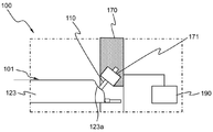
도 3에는 내압이 증가된 전지셀의 상태 및 전지셀의 팽창을 감지하기 위한 프로브를 포함하고 있는 전지모듈의 일부 모식도가 도시되어 있다.3 is a partial schematic view of a battery module including a battery cell having an increased internal pressure and a probe for detecting the expansion of the battery cell.
도 3을 참조하면, 전지모듈(100)은 전지셀(101)의 내부 압력 변화를 감지하여 신호를 송신하는 센싱 프로브(110) 및 센싱 프로브(110)로부터 신호를 수신하고 전지모듈(100)의 안전성 확보를 위한 경고 신호를 생성하는 제어부(190)를 포함하여 구성되어 있다.3, the
전극조립체 수납부(123)의 측면(123a)은 저면을 기준으로 75도로 기울어져 있고, 센싱 프로브(110)는 전지셀(101)의 전극 단자들(도 2: 141, 142)이 위치하는 측면(123a)의 바깥면(123a'')에 접하도록 설치되어 있다.The
전극조립체 수납부(123)의 측면(123a)은 전극조립체(130)와 접하는 내측면(123a')과 센싱 프로브(110)와 접하는 바깥면(123a'') 중에서, 센싱 프로브(110)가 전극조립체 수납부(123)의 측면(123a)과 마주하는 바깥면(123a'')에 설치되어 전지셀(101)의 충방전 과정에서 내압이 증가함에 따라 전극조립체 수납부(123)의 측면(123a'')과 접하게 된다.The
모듈 케이스(170)는 전지셀(101)을 내부에 수납하고 있고, 그 내부에는 센싱 프로브(110)의 외형에 대응하는 형상의 프로브 장착부(171)가 형성되어 있다.The
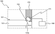
도 4에는 3의 전지셀에서 내압이 증가된 상태를 나타내는 전지모듈의 일부 모식도가 도시되어 있고, 도 5에는 4의 전지셀에서 내압이 더 증가된 상태를 나타내는 전지모듈의 일부 모식도가 도시되어 있다.4 is a partial schematic view of the battery module showing a state in which the internal pressure of the battery cell 3 is increased, and FIG. 5 is a partial schematic view of the battery module showing a state in which the internal pressure is further increased in the battery cell 4 .
도 4 및 도 5를 함께 참조하면, 센싱 프로브(110)가 모듈 케이스(170)의 내부에 센싱 프로브(110)의 외형에 대응하는 형상의 프로브 장착부(171)에 고정되어 있다.4 and 5, the
전극조립체 수납부(123)의 내부 압력이 증가하면 전극조립체 수납부(123)의 측면(123a)이 팽창하고, 센싱 프로브(110)가 전지셀(101)의 압력을 검출하여 제어부(190)에 전송한다.When the internal pressure of the electrode
전극조립체 수납부(123)의 측면(123a)이 내부 압력이 증가하여 부피가 증가하는 점을 제외하면 도 3의 구조와 동일하므로 중복되는 설명은 생략한다.3 is the same as that of FIG. 3 except that the
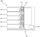
도 6에는 본 발명의 다른 실시예에 따른 전지모듈의 일부 모식도가 도시되어 있다.6 is a partial schematic view of a battery module according to another embodiment of the present invention.
도 6을 참조하면, 전지모듈(200)은 모듈 케이스(270) 내에 충방전이 가능한 다수의 전지셀들(201, 202, 203, 204, 205)을 포함하고 있다. 전지셀들(201, 202, 203, 204, 205)은 지면을 기준으로 수직 방향으로 적층되어 있다.Referring to FIG. 6, the
센싱 프로브들(210, 211)은 전지셀들(201, 202, 203, 204, 205)의 두께에 따라 경사가 조정되어 장착되어 있다. 센싱 프로브들(210, 211)이 다수의 전지셀들(201, 202, 203, 204, 205) 중 일부의 전지셀(201, 205)의 측면에 설치되어 있고, 각각의 전지셀들(201, 202, 203, 204, 205)의 측면에 장착될 수도 있다.The sensing probes 210 and 211 are mounted with their inclination adjusted according to the thickness of the
센싱 프로브들(210, 211)은 검출한 신호들을 제어부(290)로 전송하고, 제어부(290)는 내부 압력이 임계 압력값 이상일 때 경고 신호를 생성할지에 대해 판단한다.The sensing probes 210 and 211 transmit the detected signals to the
센싱 프로브들(210, 211)이 다수의 전지셀들(201, 202, 203, 204, 205)에 설치되어 있는 점을 제외하면 구조가 동일하므로 중복되는 설명은 생략한다.Except that the sensing probes 210 and 211 are provided in the plurality of
본 발명이 속한 분야에서 통상의 지식을 가진 자라면, 상기 내용을 바탕으로 본 발명의 범주 내에서 다양한 응용 및 변형을 행하는 것이 가능할 것이다.Those skilled in the art will appreciate that various modifications, additions and substitutions are possible, without departing from the scope and spirit of the invention as disclosed in the accompanying claims.
Claims (18)
상기 전지셀들 중의 적어도 하나의 전지셀의 외면에 설치되어, 전지셀의 국부적인 부피 팽창 변화를 감지하여 신호를 송신하는 센싱 프로브; 및
상기 센싱 프로브로부터 신호를 수신하고, 수신된 신호로부터 전지셀의 내부 압력을 추정하여 임계 압력값 이상일 때 전지모듈의 안전성 확보를 위한 경고 신호를 생성하는 제어부;
를 포함하고 있는 것을 특징으로 하는 전지모듈.A battery module comprising at least two battery cells capable of charging and discharging,
A sensing probe installed on an outer surface of at least one of the battery cells to sense a change in a local volume expansion of the battery cell and transmit a signal; And
A controller receiving a signal from the sensing probe and estimating an internal pressure of the battery cell from the received signal and generating a warning signal for securing the safety of the battery module when the internal pressure of the battery cell is equal to or greater than a critical pressure value;
The battery module comprising:
Priority Applications (7)
| Application Number | Priority Date | Filing Date | Title |
|---|---|---|---|
| KR1020150140182A KR101950463B1 (en) | 2015-10-06 | 2015-10-06 | Battery Module Having Prove for Sensing Expansion of Battery Cell |
| EP16853844.5A EP3255720B1 (en) | 2015-10-06 | 2016-09-29 | Battery module comprising probe for sensing expansion of battery cell |
| US15/555,858 US10476068B2 (en) | 2015-10-06 | 2016-09-29 | Battery module including probe for detecting expansion of battery cell |
| PL16853844T PL3255720T3 (en) | 2015-10-06 | 2016-09-29 | Battery module comprising probe for sensing expansion of battery cell |
| JP2017547532A JP6442074B2 (en) | 2015-10-06 | 2016-09-29 | Battery module including a probe for sensing expansion of a battery cell |
| PCT/KR2016/010900 WO2017061728A1 (en) | 2015-10-06 | 2016-09-29 | Battery module comprising probe for sensing expansion of battery cell |
| CN201680022625.5A CN107534191B (en) | 2015-10-06 | 2016-09-29 | Battery module including probe for detecting swelling of battery cell |
Applications Claiming Priority (1)
| Application Number | Priority Date | Filing Date | Title |
|---|---|---|---|
| KR1020150140182A KR101950463B1 (en) | 2015-10-06 | 2015-10-06 | Battery Module Having Prove for Sensing Expansion of Battery Cell |
Publications (2)
| Publication Number | Publication Date |
|---|---|
| KR20170040919A true KR20170040919A (en) | 2017-04-14 |
| KR101950463B1 KR101950463B1 (en) | 2019-02-20 |
Family
ID=58487935
Family Applications (1)
| Application Number | Title | Priority Date | Filing Date |
|---|---|---|---|
| KR1020150140182A KR101950463B1 (en) | 2015-10-06 | 2015-10-06 | Battery Module Having Prove for Sensing Expansion of Battery Cell |
Country Status (7)
| Country | Link |
|---|---|
| US (1) | US10476068B2 (en) |
| EP (1) | EP3255720B1 (en) |
| JP (1) | JP6442074B2 (en) |
| KR (1) | KR101950463B1 (en) |
| CN (1) | CN107534191B (en) |
| PL (1) | PL3255720T3 (en) |
| WO (1) | WO2017061728A1 (en) |
Cited By (7)
| Publication number | Priority date | Publication date | Assignee | Title |
|---|---|---|---|---|
| KR20200036960A (en) | 2018-09-28 | 2020-04-08 | 한국철도기술연구원 | Sterilizing Air Putifier |
| KR20200127717A (en) | 2019-05-03 | 2020-11-11 | 주식회사 엘지화학 | Danger sensing battery cell |
| KR20210021174A (en) | 2019-08-14 | 2021-02-25 | 한국철도기술연구원 | Sterilizing filter |
| WO2021235652A1 (en) | 2020-05-20 | 2021-11-25 | 주식회사 엘지에너지솔루션 | Pouch-type secondary battery including pressure-sensing device for measuring internal pressure |
| WO2022014888A1 (en) | 2020-07-15 | 2022-01-20 | 주식회사 엘지에너지솔루션 | Pouch-type secondary battery having improved safety, and battery module comprising same |
| KR20230053057A (en) * | 2021-10-13 | 2023-04-21 | 주식회사 성우하이텍 | Electric vehicle battery management system and method therefor |
| WO2023163394A1 (en) * | 2022-02-28 | 2023-08-31 | 주식회사 엘지에너지솔루션 | Pouch cell venting detection device |
Families Citing this family (10)
| Publication number | Priority date | Publication date | Assignee | Title |
|---|---|---|---|---|
| US20150276636A1 (en) * | 2014-03-28 | 2015-10-01 | Intel Corporation | Device to detect battery expansion |
| US10714795B2 (en) * | 2017-05-01 | 2020-07-14 | Infineon Technologies Ag | Monitoring battery cell internal pressure |
| WO2018232629A1 (en) * | 2017-06-21 | 2018-12-27 | 深圳市柔宇科技有限公司 | Mobile terminal and battery bulge detecting device |
| JP7211246B2 (en) * | 2019-04-22 | 2023-01-24 | トヨタ自動車株式会社 | BATTERY MANUFACTURING METHOD AND BATTERY |
| JP7306645B2 (en) * | 2019-11-20 | 2023-07-11 | エルジー エナジー ソリューション リミテッド | Apparatus and method for detecting swelling of battery module |
| US11215519B2 (en) * | 2020-02-20 | 2022-01-04 | Lenovo (Singapore) Pte. Ltd. | Device component swelling detection |
| KR20210128196A (en) | 2020-04-16 | 2021-10-26 | 주식회사 엘지에너지솔루션 | Battery Pack for swelling detection |
| KR20220056445A (en) | 2020-10-28 | 2022-05-06 | 주식회사 엘지에너지솔루션 | Battery Pack Comprising Sensor Member |
| CN112886082B (en) * | 2021-01-12 | 2022-04-15 | 中国汽车技术研究中心有限公司 | Power battery thermal runaway early warning method and device, electronic equipment and medium |
| CN113267299B (en) * | 2021-05-17 | 2023-02-17 | 中国第一汽车股份有限公司 | Battery box body leakage detection device and detection method |
Citations (3)
| Publication number | Priority date | Publication date | Assignee | Title |
|---|---|---|---|---|
| KR20060110576A (en) * | 2005-04-20 | 2006-10-25 | 주식회사 엘지화학 | Secondary battery module having piezo sensor |
| KR20070093165A (en) * | 2006-03-13 | 2007-09-18 | 주식회사 엘지화학 | Battery module having stability means of simple structure |
| KR20130040575A (en) * | 2011-10-14 | 2013-04-24 | 삼성에스디아이 주식회사 | Apparatus and method for detecting failure of battery |
Family Cites Families (23)
| Publication number | Priority date | Publication date | Assignee | Title |
|---|---|---|---|---|
| JP3993320B2 (en) * | 1998-08-28 | 2007-10-17 | 三菱電線工業株式会社 | Sheet battery and manufacturing method thereof |
| KR20000051638A (en) | 1999-01-25 | 2000-08-16 | 김순택 | Secondary battery |
| EP1406340B1 (en) * | 2001-06-05 | 2008-07-23 | GS Yuasa Corporation | Storage battery device and power source apparatus comprising it |
| KR100579377B1 (en) * | 2004-10-28 | 2006-05-12 | 삼성에스디아이 주식회사 | Secondary battery |
| WO2007029941A1 (en) | 2005-09-07 | 2007-03-15 | Lg Chem, Ltd. | Secondary battery employing safety device |
| KR20070075927A (en) | 2006-01-17 | 2007-07-24 | 주식회사 엘지화학 | Small-sized battery pack of improved stability |
| JP5219587B2 (en) * | 2008-03-31 | 2013-06-26 | 三洋電機株式会社 | Laminated battery and battery module including the laminated battery |
| KR101072955B1 (en) | 2009-08-14 | 2011-10-12 | 에스비리모티브 주식회사 | Battery module |
| KR101093928B1 (en) * | 2009-11-26 | 2011-12-13 | 삼성에스디아이 주식회사 | Battery pack capable of preventing battery cell from high temperature swelling and method thereof |
| KR101351427B1 (en) | 2010-02-12 | 2014-01-14 | 주식회사 엘지화학 | Apparatus for monitoring and controlling swelling of secondary cell |
| JP5489797B2 (en) * | 2010-03-17 | 2014-05-14 | 三菱重工業株式会社 | Battery system |
| KR101264527B1 (en) * | 2010-03-19 | 2013-05-14 | 주식회사 엘지화학 | Pouch case and battery pack using the same |
| KR101152662B1 (en) | 2010-09-03 | 2012-06-15 | (주)열린기술 | Apparatus for preventing explosion of secondary battery |
| US8986866B2 (en) * | 2010-11-29 | 2015-03-24 | Apple Inc. | Fault detection and monitoring in batteries |
| JP5916623B2 (en) * | 2010-11-30 | 2016-05-11 | 住友理工株式会社 | Power storage device |
| KR101965447B1 (en) * | 2011-10-07 | 2019-04-03 | 현대모비스 주식회사 | Battery Pack and Battery Pack type Battery Module |
| KR101383167B1 (en) * | 2011-10-20 | 2014-04-10 | 주식회사 엘지화학 | Battery Pack of Improved Safety |
| KR101402719B1 (en) * | 2012-06-08 | 2014-06-03 | (주)고려진공안전 | traffic sign board |
| TW201407179A (en) * | 2012-08-12 | 2014-02-16 | Compal Electronics Inc | Electronic device and method for detecting swelling of battery thereof |
| KR101944837B1 (en) | 2012-09-28 | 2019-02-07 | 에스케이이노베이션 주식회사 | Overcharge Prevent Apparatus for Battery-cell of Secondary Battery |
| KR101449306B1 (en) * | 2013-06-28 | 2014-10-08 | 현대자동차주식회사 | Safety unit for overcharge of battery |
| KR101558694B1 (en) * | 2013-12-18 | 2015-10-07 | 현대자동차주식회사 | High voltage battery for vehicle |
| KR20150071571A (en) * | 2013-12-18 | 2015-06-26 | 현대자동차주식회사 | Apparatus for preventing over-charge for battery of vehicle |
-
2015
- 2015-10-06 KR KR1020150140182A patent/KR101950463B1/en active IP Right Grant
-
2016
- 2016-09-29 PL PL16853844T patent/PL3255720T3/en unknown
- 2016-09-29 EP EP16853844.5A patent/EP3255720B1/en active Active
- 2016-09-29 JP JP2017547532A patent/JP6442074B2/en active Active
- 2016-09-29 US US15/555,858 patent/US10476068B2/en active Active
- 2016-09-29 WO PCT/KR2016/010900 patent/WO2017061728A1/en active Application Filing
- 2016-09-29 CN CN201680022625.5A patent/CN107534191B/en active Active
Patent Citations (3)
| Publication number | Priority date | Publication date | Assignee | Title |
|---|---|---|---|---|
| KR20060110576A (en) * | 2005-04-20 | 2006-10-25 | 주식회사 엘지화학 | Secondary battery module having piezo sensor |
| KR20070093165A (en) * | 2006-03-13 | 2007-09-18 | 주식회사 엘지화학 | Battery module having stability means of simple structure |
| KR20130040575A (en) * | 2011-10-14 | 2013-04-24 | 삼성에스디아이 주식회사 | Apparatus and method for detecting failure of battery |
Cited By (10)
| Publication number | Priority date | Publication date | Assignee | Title |
|---|---|---|---|---|
| KR20200036960A (en) | 2018-09-28 | 2020-04-08 | 한국철도기술연구원 | Sterilizing Air Putifier |
| KR20200127717A (en) | 2019-05-03 | 2020-11-11 | 주식회사 엘지화학 | Danger sensing battery cell |
| WO2020226303A1 (en) | 2019-05-03 | 2020-11-12 | 주식회사 엘지화학 | Battery cell for detecting danger |
| KR20210021174A (en) | 2019-08-14 | 2021-02-25 | 한국철도기술연구원 | Sterilizing filter |
| WO2021235652A1 (en) | 2020-05-20 | 2021-11-25 | 주식회사 엘지에너지솔루션 | Pouch-type secondary battery including pressure-sensing device for measuring internal pressure |
| KR20210143603A (en) | 2020-05-20 | 2021-11-29 | 주식회사 엘지에너지솔루션 | Pouch type secondary battery having the Pressure Measuring Device for measuring the internal pressure |
| WO2022014888A1 (en) | 2020-07-15 | 2022-01-20 | 주식회사 엘지에너지솔루션 | Pouch-type secondary battery having improved safety, and battery module comprising same |
| KR20220009009A (en) | 2020-07-15 | 2022-01-24 | 주식회사 엘지에너지솔루션 | Pouch type secondary battery with improved safety and Battery module including the same |
| KR20230053057A (en) * | 2021-10-13 | 2023-04-21 | 주식회사 성우하이텍 | Electric vehicle battery management system and method therefor |
| WO2023163394A1 (en) * | 2022-02-28 | 2023-08-31 | 주식회사 엘지에너지솔루션 | Pouch cell venting detection device |
Also Published As
| Publication number | Publication date |
|---|---|
| KR101950463B1 (en) | 2019-02-20 |
| JP6442074B2 (en) | 2018-12-19 |
| US20180047972A1 (en) | 2018-02-15 |
| CN107534191A (en) | 2018-01-02 |
| EP3255720A4 (en) | 2018-07-25 |
| EP3255720A1 (en) | 2017-12-13 |
| JP2018508107A (en) | 2018-03-22 |
| WO2017061728A1 (en) | 2017-04-13 |
| US10476068B2 (en) | 2019-11-12 |
| PL3255720T3 (en) | 2021-05-17 |
| CN107534191B (en) | 2020-07-14 |
| EP3255720B1 (en) | 2020-11-18 |
Similar Documents
| Publication | Publication Date | Title |
|---|---|---|
| KR101950463B1 (en) | Battery Module Having Prove for Sensing Expansion of Battery Cell | |
| US9653724B2 (en) | Secondary battery, and secondary battery module and secondary battery pack comprising the same | |
| CN107949932B (en) | Battery cell having venting structure using adhesive tape | |
| EP2357685B1 (en) | Rechargeable battery | |
| RU2468477C2 (en) | Accumulator battery of middle or large size of increased security | |
| EP2768047A1 (en) | Battery pack having improved safety | |
| US11975615B2 (en) | Vehicle battery fire sensing apparatus and method | |
| US12087918B2 (en) | Vehicle battery fire sensing apparatus and method | |
| KR102080903B1 (en) | Electrode lead and secondary battery including the same | |
| KR102250180B1 (en) | Battery module, battery pack including the same, and vehicle including the same | |
| KR101487152B1 (en) | Unit Module Assembly and Battery Module Comprising The Same | |
| US10847980B2 (en) | Battery module | |
| KR20120136826A (en) | Apparatus for preventing from over-charging battery | |
| KR102267056B1 (en) | Battery module, battery pack including the same, and vehicle including the same | |
| US20160149168A1 (en) | Receptacle Device, Battery, and Motor Vehicle | |
| KR20160103255A (en) | Battery Pack Having Small PCM | |
| KR20200084403A (en) | Battery module for electric vehicles and control methode thereof | |
| KR102104966B1 (en) | Battery Cell Having Sealing Protrusion Between Electrode Terminals | |
| KR20200104614A (en) | Battery pack having bending shaped sensing bus bar and device including the same | |
| KR20190112579A (en) | Sensing bus bar for reducing voltage deviation | |
| US20240021888A1 (en) | Battery module having electrolytic solution leakage detection function and battery pack including the same | |
| KR101211217B1 (en) | Pouch type secondary battery capable of preventing short between electrode lead | |
| KR20140146936A (en) | Battery cell with improved safety and method of manufacturing the same |
Legal Events
| Date | Code | Title | Description |
|---|---|---|---|
| A201 | Request for examination | ||
| E902 | Notification of reason for refusal | ||
| E701 | Decision to grant or registration of patent right | ||
| GRNT | Written decision to grant |