KR20170036065A - Acceleration-sensing electrochemical pressure sensor compositions - Google Patents
Acceleration-sensing electrochemical pressure sensor compositions Download PDFInfo
- Publication number
- KR20170036065A KR20170036065A KR1020177005311A KR20177005311A KR20170036065A KR 20170036065 A KR20170036065 A KR 20170036065A KR 1020177005311 A KR1020177005311 A KR 1020177005311A KR 20177005311 A KR20177005311 A KR 20177005311A KR 20170036065 A KR20170036065 A KR 20170036065A
- Authority
- KR
- South Korea
- Prior art keywords
- accelerometer
- conductive foam
- electrode
- sensor
- bracket
- Prior art date
Links
Images


Classifications
-
- G—PHYSICS
- G01—MEASURING; TESTING
- G01L—MEASURING FORCE, STRESS, TORQUE, WORK, MECHANICAL POWER, MECHANICAL EFFICIENCY, OR FLUID PRESSURE
- G01L5/00—Apparatus for, or methods of, measuring force, work, mechanical power, or torque, specially adapted for specific purposes
- G01L5/0052—Apparatus for, or methods of, measuring force, work, mechanical power, or torque, specially adapted for specific purposes measuring forces due to impact
-
- A—HUMAN NECESSITIES
- A41—WEARING APPAREL
- A41D—OUTERWEAR; PROTECTIVE GARMENTS; ACCESSORIES
- A41D1/00—Garments
- A41D1/002—Garments adapted to accommodate electronic equipment
-
- A—HUMAN NECESSITIES
- A41—WEARING APPAREL
- A41D—OUTERWEAR; PROTECTIVE GARMENTS; ACCESSORIES
- A41D20/00—Wristbands or headbands, e.g. for absorbing sweat
-
- A—HUMAN NECESSITIES
- A42—HEADWEAR
- A42B—HATS; HEAD COVERINGS
- A42B3/00—Helmets; Helmet covers ; Other protective head coverings
- A42B3/04—Parts, details or accessories of helmets
- A42B3/0406—Accessories for helmets
- A42B3/0433—Detecting, signalling or lighting devices
- A42B3/046—Means for detecting hazards or accidents
-
- A—HUMAN NECESSITIES
- A63—SPORTS; GAMES; AMUSEMENTS
- A63B—APPARATUS FOR PHYSICAL TRAINING, GYMNASTICS, SWIMMING, CLIMBING, OR FENCING; BALL GAMES; TRAINING EQUIPMENT
- A63B71/00—Games or sports accessories not covered in groups A63B1/00 - A63B69/00
- A63B71/08—Body-protectors for players or sportsmen, i.e. body-protecting accessories affording protection of body parts against blows or collisions
- A63B71/10—Body-protectors for players or sportsmen, i.e. body-protecting accessories affording protection of body parts against blows or collisions for the head
-
- G—PHYSICS
- G01—MEASURING; TESTING
- G01P—MEASURING LINEAR OR ANGULAR SPEED, ACCELERATION, DECELERATION, OR SHOCK; INDICATING PRESENCE, ABSENCE, OR DIRECTION, OF MOVEMENT
- G01P15/00—Measuring acceleration; Measuring deceleration; Measuring shock, i.e. sudden change of acceleration
- G01P15/02—Measuring acceleration; Measuring deceleration; Measuring shock, i.e. sudden change of acceleration by making use of inertia forces using solid seismic masses
- G01P15/08—Measuring acceleration; Measuring deceleration; Measuring shock, i.e. sudden change of acceleration by making use of inertia forces using solid seismic masses with conversion into electric or magnetic values
- G01P15/12—Measuring acceleration; Measuring deceleration; Measuring shock, i.e. sudden change of acceleration by making use of inertia forces using solid seismic masses with conversion into electric or magnetic values by alteration of electrical resistance
Abstract
브래킷(110), 한 쌍의 전극(210/220/230/240/250), 제 1 도전성 발포체(120), 제 2 도전성 발포체(130)를 포함하는 가속도계(100)로서, 상기 한 쌍의 전극과 브래킷 사이에 제 1 도전성 발포체 및 제 2 도전성 발포체가 삽입된다.An accelerometer (100) comprising a bracket (110), a pair of electrodes (210/220/230/240/250), a first conductive foam (120) and a second conductive foam (130) The first conductive foam and the second conductive foam are inserted between the brackets.
Description
관련 출원의 상호 참조Cross reference of related application
본 출원은 2014년 7월 25일에 출원된 미국 가특허출원 번호 62/029,176에 대해 우선권을 주장한다.This application claims priority to U.S. Provisional Patent Application No. 62 / 029,176, filed on July 25, 2014.
발명의 분야Field of invention
폴리우레탄 발포체를 기초로 한 가속도계는 개시되어 있다.An accelerometer based on polyurethane foam is disclosed.
일상적으로, 가속도계는 일반적인 전자장치, 수송 및 심지어 의료 장치의 기능 및 유용성을 개선하는데 중요한 역할을 한다. 휴대 전화의 움직임의 검출로부터, 가속도계는 자동차 사고 시의 에어백의 전개, 가전 제품의 조기 고장 검출, 및 지진의 검출을 모두 가능하게 한다. 착용가능한 의료 장치 및 이식가능한 의료 장치의 양자 모두의 대두에 따라 가속도계는 통상적으로 환자의 진단의 보조기구로서 사용되고 있다. On a routine basis, accelerometers play an important role in improving the functionality and usability of common electronic devices, transport, and even medical devices. From the detection of the movement of the mobile phone, the accelerometer enables the deployment of the airbag at the time of a car accident, the early failure detection of appliances, and the detection of an earthquake. Depending on the soybeans of both wearable medical devices and implantable medical devices, accelerometers are typically used as aids in the diagnosis of patients.
본 발명은 도면을 참조한 다음의 상세한 설명으로부터 더 깊이 이해될 것이다. 도면에서 동일한 참조부호는 동일한 요소를 표시하기 위해 사용된다.The invention will be better understood from the following detailed description with reference to the drawings. In the drawings, the same reference numerals are used for the same elements.
도 1a는 출원인의 어셈블리(100)의 측면도이고;
도 1b는 출원인의 어셈블리(102)의 측면도이고;
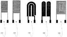
도 2는 센서(210, 220, 230, 240, 250)의 디자인이고;
도 3a는 출원인의 모두 5개의 가속도 전극 보드의 6.28Hz에서의 고속 퓨리에 변환을 도시하고;
도 3b는 6.28Hz에서 MMA7361 가속도계에 의해 발생된 데이터의 고속 퓨리에 변환을 도시하고;
도 4a는 출원인의 모두 5개의 가속도 전극 보드의 8.3528Hz에서의 고속 퓨리에 변환을 도시하고;
도 4b는 8.35Hz에서 MMA7361 가속도계에 의해 발생된 데이터의 고속 퓨리에 변환을 도시하고;
도 5a는 출원인의 모두 5개의 가속도 전극 보드의 11.00Hz에서의 고속 퓨리에 변환을 도시하고;
도 5b는 11.00Hz에서 MMA7361 가속도계에 의해 발생된 데이터의 고속 퓨리에 변환을 도시하고;
도 6, 도 7, 및 도 8은 각각 6.28Hz, 8.35Hz, 및 11.00Hz의 원하는 주파수 피크와 각각의 센서의 고조파의 피크에 대한 정규화 값의 그래프이고;
도 9는 전류에 대한 출원인의 가속도계 관련 힘의 보정 곡선이다.IA is a side view of applicant's
1B is a side view of applicant's
Figure 2 is a design of
Figure 3a shows a fast Fourier transform at 6.28 Hz of all five acceleration electrode boards of the applicant;
Figure 3b shows a fast Fourier transform of data generated by the MMA7361 accelerometer at 6.28 Hz;
4A shows a fast Fourier transform at 8.3528 Hz for all five acceleration electrode boards of the applicant;
Figure 4b shows a fast Fourier transform of the data generated by the MMA7361 accelerometer at 8.35 Hz;
5A shows a fast Fourier transform at 11.00 Hz of all five acceleration electrode boards of the applicant;
Figure 5B shows a fast Fourier transform of data generated by the MMA 7361 accelerometer at 11.00 Hz;
Figures 6, 7, and 8 are graphs of normalized values for the desired frequency peaks at 6.28 Hz, 8.35 Hz, and 11.00 Hz and the peaks of harmonics for each sensor, respectively;
Figure 9 is a calibration curve of the applicant's accelerometer related force for current.
본 발명은 도면을 참조한 다음의 설명에서 바람직한 실시형태로 설명되고, 여기서 동일한 번호는 동일하거나 유사한 요소를 표시한다. 본 명세서의 전체를 통해 언급되는 "하나의 실시형태", "일 실시형태" 또는 이와 유사한 용어는 이 실시형태와 관련하여 설명되는 특정의 기구, 구조 또는 특성이 본 발명의 적어도 하나의 실시형태 내에 포함됨을 의미한다. 따라서, 본 명세서의 전체를 통해 나타나는 "하나의 실시형태에서", "일 실시형태에서" 및 이와 유사한 용어는 모두 동일한 실시형태를 지칭할 수 있으나, 필수적인 것은 아니다.The present invention is illustrated in the following description with reference to the drawings, in which like numerals denote like or similar elements. It is to be understood that "one embodiment", "one embodiment", or the like, which is referred to throughout this specification, means that a particular feature, structure, or characteristic described in connection with this embodiment is within the scope of at least one embodiment . Thus, the appearances of the phrases " in an embodiment, "" in an embodiment," and similar terms appearing throughout this specification may all refer to the same embodiment, but are not required.
본 발명의 설명된 기구, 구조, 또는 특성은 하나 이상의 실시형태에서 임의의 적절한 방식으로 조합될 수 있다. 다음의 설명에서, 본 발명의 실시형태의 철저한 이해를 돕기 위해 다수의 구체적인 세부내용이 열거된다. 그러나, 관련 기술분야의 당업자는 본 발명이 이 구체적인 세부내용 중 하나 이상을 포함하지 않은 상태로, 또는 다른 방법, 컴포넌트, 재료 등을 포함하여 실시될 수 있다는 것을 인식할 것이다. 다른 경우에, 본 발명의 양태를 모호하게 하지 않도록 하기 위해 주지의 구조, 재료, 또는 작동은 상세히 설명되지 않는다.The described mechanism, structure, or characteristic of the invention may be combined in any suitable manner in one or more embodiments. In the following description, numerous specific details are set forth in order to provide a thorough understanding of embodiments of the present invention. However, those skilled in the relevant art will recognize that the present invention may be practiced without one or more of these specific details, or with other methods, components, materials, and so on. In other instances, well-known structures, materials, or operations are not described in detail so as not to obscure aspects of the present invention.
특정의 실시형태에서, 출원인의 장치는 일회성 "텔테일(telltale)" 가속도계로서 사용될 수 있다. 다른 실시형태에서, 출원인의 장치는 실시간 응답으로 여러번 반복하여 사용될 수 있다. 용도는 스포츠 헬멧(즉, 특정의 한계치를 구비하는 텔테일의 양호한 용도)을 위한 내부 가속도계 또는 외부 가속도계일 수 있다. 다른 구현형태는 공기하중, 예하중(텔테일)의 측정값으로서의 구조 하중, 충격 시험 및 탄도 시험(심지어 탱크 및 기타 차량에 적용될 수 있는 동체 방호구를 포함함), 음향 하중(다른 방법으로는 측정이 곤란함), 지상 하중 등을 포함한다.In certain embodiments, applicant's apparatus may be used as a one-time "telltale" accelerometer. In another embodiment, applicant's apparatus may be used multiple times in real-time response. The application may be an internal accelerometer or an external accelerometer for a sports helmet (i. E., Good use of a teletail with a certain threshold). Other implementations may include, but are not limited to, air loads, structural loads as measured values of the preload (teltel), impact tests and ballistic tests (including even fuselage guards that may be applied to tanks and other vehicles), acoustic loads Measurement difficult), ground load, and the like.
출원인의 폴리우레탄 발포체를 기초로 한 가속도계는 확장가능하고, 저비용이고, 견고한 센서를 제공한다. 본 출원인의 가속도계는 크기, 검출 방법, 감도 범위, 및 상업용 가속도계용으로 통상적으로 부적당한 용도로 설계되는 능력의 면에서 종래의 가속도계와 다르다. Applicants' polyurethane foam-based accelerometers provide a scalable, low-cost, and robust sensor. Applicants' accelerometers are different from conventional accelerometers in terms of size, detection method, sensitivity range, and ability to be designed for applications typically unsuitable for commercial accelerometers.
특정의 실시형태에서, 출원인의 장치는 PCB 센서, 중량체, 및 이 중량체를 포함하는 2개의 부재의 도전성 폴리우레탄 발포체의 3개의 주요 컴포넌트를 포함한다. In a particular embodiment, Applicant's apparatus comprises a PCB sensor, a weight, and three major components of a two-element conductive polyurethane foam comprising this weight.
PCB를 기초로 한 구리 및 금 도금 센서는 중량 또는 발포체의 유형을 조절함으로써 다양한 용도에 적용될 수 있다. 발포체는 두께, 밀도, 및 조성이 상이할 수 있고, 각각은 특정의 다이내믹 레인지(dynamic range) 및 동적 반응의 달성을 허용한다. PCB-based copper and gold-plated sensors can be applied to a variety of applications by controlling the weight or type of foam. The foams may be different in thickness, density, and composition, each allowing a specific dynamic range and dynamic response to be achieved.
출원인의 가속도계는 5개의 상이한 센서 디자인을 사용하여 6.281Hz, 8.353Hz, 및 11.000Hz의 3가지 주파수로 시험되었다. 시간의 경과 및 조건의 변화에 따른 센서의 거동을 결정하기 위해 전도성 폴리우레탄 발포체의 처리가 또한 시험되었다. 발포체 센서의 굴곡가능한 성질은 헬멧의 내부, 팔다리의 주위, 또는 신발의 발다닥 내부를 포함하는 곡면을 따른 부착을 가능하게 한다. 신호 검출은 현재 출시되어 있는 종래의 가속도계에 비해 독특한 접근방법인 전류측정 및 사이클릭 볼타메트리의 사용을 통해 수행된다. 출원인의 가속도계의 전체적인 크기, 범위, 및 확장가능성은 의료 분야 및 스포츠 분야에서 많은 용도에 대해 큰 도움을 준다.Applicants' accelerometers were tested at three frequencies of 6.281 Hz, 8.353 Hz, and 11.000 Hz using five different sensor designs. The treatment of the conductive polyurethane foam was also tested to determine the behavior of the sensor over time and with changes in conditions. The bendable nature of the foam sensor allows attachment along curved surfaces, including the interior of the helmet, the peripheries of the limbs, or the footprint of the shoe. Signal detection is accomplished through the use of current measurement and cyclic voltammetry, a unique approach compared to current accelerometers. Applicant's overall size, range, and scalability of the accelerometer is of great benefit for many applications in the medical and sports arenas.
출원인의 가속도계의 잠재적 용도는 오락의 목적을 위해 또는 체육 활동을 위해 현장에서 헬멧을 착용하고 있는 사람에게 지속되는 충격력 및 결과적인 머리 부상을 모니터링하는 것을 포함한다. 가속도계의 발포체 구조는 용이한 모니터링을 위한 패딩을 가진 헬멧의 내부에서의 결합에 큰 도움을 준다. 사람에 대한 충격의 강도, 지속시간, 및 국부 영역의 검출은 외상성 뇌손상의 치료 및 감소를 위한 귀중한 정보일 수 있다. 외상성 뇌손상은 머리에 대한 급격한 가속, 감속, 또는 충격력에 기인된다. 통상적으로 스포츠와 관련된 부상으로 생각되지만 외상성 뇌손상은 많은 상이한 메커니즘의 결과이고, 미국에서 매일 138명을 사망자를 내는 주요 원인이다. The potential use of the applicant's accelerometer includes monitoring the ongoing impact and resultant head injury to a person wearing a helmet for the purpose of entertainment or for athletic activity in the field. The foam structure of the accelerometer is a great help in the bonding of the inside of the helmet with padding for easy monitoring. Detection of the intensity, duration, and local area of impact on a person can be valuable information for the treatment and reduction of traumatic brain injury. Traumatic brain injury is caused by sudden acceleration, deceleration, or impact on the head. Traumatic brain injury is usually the result of many different mechanisms, though it is thought to be a sports related injury, and is the leading cause of death to 138 people in the US daily.
외상성 뇌손상은 고교 운동선수 및 군인에게 점점 더 큰 문제가 되고 있듯이 임의의 연령 범위에 특유한 것은 아니다. 발견되지 않거나 또는 보장성 치료 또는 보고를 요할 정도로 심각하지 않은 많은 심각도의 레벨이 존재하므로 보고된 외상성 뇌손상의 사례는 실재보다 훨씬 더 적을 것으로 생각된다. 더욱이, 헬멧의 정확하게 기능하는 수명은 유한하므로 사용자에게 부상을 일으키기 전에 교체될 필요가 있고, 충격 데이터가 축적된 다른 경우 충격 데이터는 안전의 관점에서 뿐만 아니라 비용이 관점에서도 중요하다.Traumatic brain injury is not unique to any age range, as it is increasingly a problem for high school athletes and soldiers. The reported cases of traumatic brain injury are believed to be far less likely than they are, as there are many levels of severity that are not found or are not serious enough to require protective treatment or reporting. Moreover, the precise functional lifetime of the helmet is finite, so it needs to be replaced before it can cause injury to the user, and in other cases where impact data is accumulated, impact data is important not only in terms of safety but also in terms of cost.
가속도계 데이터는 환자의 웰빙을 모니터링하기 위한 목적을 위해 착용가능하거나 이식가능한 의료 장치의 디자인에서 활용되고 있다. 이러한 장치는 사용자에 관한 다중의 데이터 점을 수집하기 위한 목적을 위해 종종 다른 센서와 조합된다. Accelerometer data is being used in the design of wearable or implantable medical devices for the purpose of monitoring patient well-being. Such a device is often combined with other sensors for the purpose of collecting multiple data points about the user.
출원인은 고밀도 폴리우레탄 정전기 방전(ESD) 발포체가 센서 디자인을 위한 바람직한 특성을 포함한다는 것을 발견하였다. ESD 발포체는 고밀도 및 저밀도, 다양한 두께, 및 다양한 발포체 화학 조성을 포함하는 수개의 변종이 있다. 전형적으로 ESD 발포체는 보관 및 수송 중에 정전기로부터 전자장치를 보호하기 위해 사용되지만, 그 전도성 특성으로 인해 이것에 다양한 힘이 가해지는 경우에 가변 저항기로서 작용할 수 있다. 압축, 굴곡 또는 신장으로 인해 발포체는 자신의 저항을 변화시키고, 그 결과 발포체는 이러한 특정의 용도를 위한 센서로서 사용될 수 있다. Applicants have discovered that high density polyurethane electrostatic discharge (ESD) foams include desirable properties for sensor design. ESD foams have several variants including high density and low density, varying thicknesses, and various foam chemistries. Typically, ESD foams are used to protect electronic devices from static electricity during storage and transportation, but they can act as variable resistors when a variety of forces are applied thereto due to their conductive nature. As a result of compression, flexing or stretching, the foam changes its resistance, so that the foam can be used as a sensor for this particular application.
본 출원인의 가속도계를 포함하는 기존의 디자인은 전도성 발포체의 천연의 형상이 변형되는 경우에 발생되는 저항 변화에 기초한다. 하나의 연구팀은 호흡 패턴을 측정하기 위해 착용가능한 조끼의 내부에 매립된 발포체를 기초로 한 센서를 사용하여 사인 곡선을 얻었다. 마찬가지로, 다른 연구팀은 육체적 운동 중인 운동선수의 호흡을 측정하기 위한 목적으로 전도성 폴리머 폴리피롤(PPy)의 층을 적층함으로써 전도성 발포체를 제조하였다.Existing designs, including Applicants' accelerometers, are based on resistance changes that occur when the natural shape of the conductive foam is deformed. One team obtained a sinusoid using a foam-based sensor embedded in a wearable vest to measure breathing patterns. Likewise, other researchers have fabricated conductive foams by layering conductive polymer polypyrroles (PPy) for the purpose of measuring the respiration of athletes under physical exercise.
매우 광범위한 동적 범위에 걸쳐 정확하게 작은 전류의 변화를 검출하기 위한 능력을 위해 포텐쇼스탯이 사용되었다. 포텐쇼스탯은 환경, 산업, 의약 및 식품 산업을 포함하는 많은 영역에 걸쳐 전기화학적 반응을 연구하기 위해 사용된다. 많은 상용 유닛은 지나치게 고가이지만 개발 분야에서의 사용을 위한 저비용의 오픈 소스(open source) 모델을 제조하기 위해 노력해왔다. 가장 단순하게, 포텐쇼스탯은 2 개의 전극, 즉 작용 전극과 대전극 사이에서 흐르는 전류의 양을 측정함으로써 기능을 발휘하고, 이것의 결과는 경과된 시간에 대한 출력이다. Potentiostats have been used for the ability to accurately detect small current changes over a very wide dynamic range. Potentiostats are used to study electrochemical reactions in many areas, including the environment, industry, medicine and food industry. While many commercial units are overly expensive, they have been trying to manufacture low cost open source models for use in development. Most simply, a potentiostat functions by measuring the amount of current flowing between two electrodes, the working electrode and the counter electrode, and the result is an output over time.
3개의 전극 구성의 포텐쇼스탯은 대전극 또는 기준 전극으로부터의 간섭을 받음이 없이 단일의 전극(작용 전극)에서의 전류 변화를 측정할 수 있다. 발포체가 굴곡, 압축 또는 신장과 같은 어떤 방식으로 변형되는 경우, 시스템에 의해 출력되는 전류가 변화된다. 이러한 방식으로 발포체의 저항 변화에 기인되는 힘이 측정될 수 있다. 이 시스템에 조정된 중량체를 가하면 중력에 기인되는 가속도가 결정될 수 있다.Potentiostats of three electrode configurations can measure the current change in a single electrode (working electrode) without interference from the counter electrode or the reference electrode. When the foam is deformed in some way, such as flexing, compressing or stretching, the current output by the system is changed. In this way, the force due to the resistance change of the foam can be measured. Applying an adjusted weight to this system can determine the acceleration due to gravity.
특정의 실시형태에서, 출원인의 가속도계는 전극의 표면에 대해 압축 상태로 발포체와 조정된 중량체를 설치하므로 어떤 유형의 접착제도 불필요하다. 이 센서는 또한 많은 상이한 용도 및 상이한 다이내믹 레인지용으로 확장가능하다. In certain embodiments, applicant's accelerometers provide foam and calibrated weights in a compressed state against the surface of the electrode, so that no type of glue is required. This sensor is also scalable for many different applications and for different dynamic ranges.
센서의 시험은 다양한 주파수에 걸친 사인 곡선으로 운동하는 가변 속도의 왕복식 톱을 사용하여 달성되었다. 시판되는 가속도계에 대한 시험은 센서 자체의 신뢰성을 입증할 수 있음과 동시에 신호 진폭 및 고조파의 분석을 가능하게 하였다.Testing of the sensor was accomplished using a variable speed, reciprocating saw that moves on a sinusoidal curve over a range of frequencies. Tests on commercially available accelerometers have proved the reliability of the sensor itself and made it possible to analyze signal amplitudes and harmonics.
재료 및 방법:Materials and Methods:
이하 도 1a 및 도 1b를 참조하면, 가속도계(100)의 본체용으로 1.588mm 두께의 스테인리스강의 시트(Industrial Metal Supply Co, Phoenix, AZ, USA)이 사용되었다. 센서의 내부를 위해 6.35mm 두께의 전도성 고밀도 폴리우레탄 발포체의 시트(ESDProduct, Torrance, CA, USA)가 사용되었다. 가속도계용 중량체로서 6.35mm 부재의 스테인리스 바 금속재료(Industrial Metal Supply Co, Phoenix, AZ, USA)가 사용되었다. 1A and 1B, a 1.588 mm thick sheet of stainless steel (Industrial Metal Supply Co., Phoenix, AZ, USA) is used for the body of the
센서의 디자인은 PADS PCB 디자인 소프트웨어(Mentor Graphics Corporation, Wilsonville, OR, USA)를 이용하여 수행되었다. 맞춤식 설계된 구리 PCB 전극이 인쇄되었고(Advanced Circuits - Tempe Division, Tempe, AZ, USA), 가속도계의 감지 부분으로서 사용되었다. 센서의 시험에서 사용된 설비는 CH Instruments Electrochemical Analyzer CHI1230A(CH Instruments, Inc., Austin, TX, USA) 및 CSI3003X5 DC 조절식 전원(Circuit Specialists, Mesa, AZ, USA)를 포함하였다. 시험은 가변 속도 왕복식 톱(Harbor Freight Tools, Tempe, AZ, USA) 상에서 수행되었다. 기타 측정 설비는 APX-60 디지털 저울(Denver Instrument, Bohemia, NY, USA), MMA7361 프리스케일 반도체 3축 가속도계(Virtuabotix LLC, Colorado Springs, CO, USA), 및 Arduino Uno Rev 3(GarageLab, Doral, FL, USA)을 포함하였다. 사용된 기타 부차적 설비는 경부하 로진 코어 솔더(Radio Shack, Fort Worth, Texas, USA)를 구비하는 EC1002 납땜용 인두(Apex Tool Group, Sparks, Maryland, USA), 다양한 길이의 와이어(General Electric, Schenectady, NY, USA), 및 M3 나사, 볼트, 및 스타 와셔, USB 케이블, 및 오픈 소스 Arduino IDE 소프트웨어(Arduino 1.0.5)를 포함하였다. 미가공 데이터의 분석은 마이크로소프트 엑셀(Microsoft Corporation, Redmond, WA, USA)을 이용하여 실시되었다.The design of the sensor was performed using PADS PCB design software (Mentor Graphics Corporation, Wilsonville, OR, USA). A custom designed copper PCB electrode was printed (Advanced Circuits - Tempe Division, Tempe, AZ, USA) and used as the sensing part of the accelerometer. The equipment used in the testing of the sensor included a CH Instruments Electrochemical Analyzer CHI1230A (CH Instruments, Inc., Austin, TX, USA) and a CSI3003X5 DC controlled power source (Circuit Specialists, Mesa, AZ, USA). The tests were performed on a variable speed reciprocating saw (Harbor Freight Tools, Tempe, AZ, USA). Other measurement equipment include the APX-60 digital scales (Denver Instrument, Bohemia, NY, USA), MMA 7361 Freescale Semiconductor 3-axis accelerometer (Virtuabotix LLC, Colorado Springs, CO, USA), and
출원인의 가속도계의 구성은 도 2에 도시된 5개의 센서의 디자인으로 시작되었다. 도 2에 도시된 다양한 센서의 인쇄 회로 보드 전극쌍이 도 1a에 도시된 센서(150)로서 개별적으로 사용되었다.The applicant's accelerometer configuration began with the design of the five sensors shown in FIG. The printed circuit board electrode pairs of the various sensors shown in FIG. 2 were used individually as the
이 디자인은 디지털화되었고, 44.45mm의 길이 x 17.78mm의 폭 x 1.5mm의 두께의 PCB 상에 인쇄되었다. The design was digitized and printed on a 44.45mm long x 17.78mm wide x 1.5mm thick PCB.
5 개의 센서 보드의 각각에 2개의 와이어(152, 154)가 납땜되었다. 이하 도 1b를 참조하면, 나사(102, 104)의 사용을 통해 브래킷에 부착시키기 위한 2개의 3mm 구멍이 감지 표면의 양 면 상에 천공되었다. Two
1.588mm 부재의 스테인리스강은 73mm x 18.5mm의 치수를 갖는 사각형으로 절단되었고, 단부로부터 16mm에서 90°의 각도로 굴곡되어 브래킷(110)을 형성하였다. 이 금속 브래킷 내에 총 4개의 3mm 구멍이 천공되었고, 2개는 시험 메커니즘에 브래킷을 장착하기 위한 것이고, 2개는 브래킷에 센서를 부착하기 위한 것이다. 이 브래킷은 왕복식 톱에 장착되었고, 이 왕복식 톱은 센서가 지면에 대해 직각이 되도록 수직으로 장착되었다. The 1.588 mm member stainless steel was cut into a square having dimensions of 73 mm x 18.5 mm and bent at an angle of 90 mm from the end to 16 mm to form the
이하 도 1b를 참조하면, 고밀도 전도성 발포체 시트로부터 18mm x 29mm의 특정의 실시형태의 치수를 갖는 사각형 부재(120, 130)가 절단되었고, 센서(150)와 브래킷(110) 사이에 삽입되었다. 도 1a를 참조하면, 특정의 실시형태에서 Referring now to FIG. 1B,
6.35mm의 스테인리스 바 금속재료(140)가 23g의 정사각 중량체로 절단되었다. 이 중량체(140)는 전술한 2개의 발포체 부재의 중간에 삽입되었다. A 6.35 mm stainless steel
다음에 센서 보드를 브래킷에 고정하는 2개의 나사(106, 108)가 조여져서 전체 어셈블리(100)는 20.2mm의 총두께를 가졌다. 이러한 공정이 시험 중인 5개의 디자인의 각각에 대해 반복되었다. 각각의 센서의 구성 중에, 금속 브래킷, 중량체, 센서 PCB는 측정에 부정적인 영향을 줄 수 있는 오염 오일 및 오물을 제거하기 위해 이소프로판올 알코올로 철저히 세척되었다. The two screws (106, 108) securing the sensor board to the bracket were then tightened so that the entire assembly (100) had a total thickness of 20.2 mm. This process was repeated for each of the five designs under test. During the construction of each sensor, metal brackets, weights, and sensor PCBs were thoroughly cleaned with isopropanol alcohol to remove contaminated oil and dirt that could negatively affect the measurement.
시험 과정Examination Process
양자 모두의 가속도계가 지면에 수직으로 장착될 수 있도록 먼저 왕복식 톱이 실험대에 클램핑되었다. 시험 중에 톱의 배터리는 사용되지 않았고, 오히려 이 톱은 반복가능하고 변화가능한 속도가 달성될 수 있도록 DC 전원에 접속되었다. The reciprocating saw was first clamped to the bench so that both accelerometers could be mounted perpendicular to the ground. During testing, the top battery was not used, but rather the saw was connected to a DC power source so that repeatable and variable speed could be achieved.
출원인의 가속도계는 톱 블레이트의 일면 상에 장착되었고, 상용 MMA7361 가속도계는 타면 상에 장착되었고, 본 시스템은 모든 시험 중에 균형이 유지되었다. MMA7361는 Arduino Uno Rev 3에 와이어로 연결되었고, 다음에 이것은 데이터 로깅을 위해 USB를 통해 컴퓨터에 접속되었다. 출원인의 가속도계는 대전극 및 센서 보드의 하나의 리드에 부착되는 기준 전극, 및 다른 리드에 부착되는 작용 전극을 구비하는 CHI1230A에 접속되었다. 모두 5개의 센서 보드 디자인 및 MMA7361 가속도계를 시험하기 위해, 동일한 CHI 기계, 발포체 직사각형, 조정된 중량체, 및 주파수 범위가 사용되었다. Applicant's accelerometer was mounted on one side of the saw blades, commercial MMA 7361 accelerometer mounted on the other side, and the system was balanced during all tests. The MMA7361 was wired to the
왕복식 톱은 MMA7361에 의해 확인되는 바와 같이 순차적으로 3V, 4V, 및 5V로 설정되었고, 이것은 각각 6.281Hz, 8.353Hz, 및 11.000Hz에 대응한다. 이러한 전압 및 주파수는 시험 메커니즘을 신뢰할 수 있는, 그리고 센서가 이후의 데이터 분석 및 후속의 최상의 작동 디자인의 선택을 위한 신호를 재현가능하게 생성할 수 있는 범위이므로 이러한 전압 및 주파수가 선택되었다The reciprocating saw was set to 3 V, 4 V, and 5 V sequentially as identified by MMA 7361, which corresponds to 6.281 Hz, 8.353 Hz, and 11.000 Hz, respectively. These voltages and frequencies were chosen because the test mechanism is reliable and the sensor is capable of reproducibly generating signals for subsequent data analysis and subsequent selection of the best operational design
데이터 분석 기법Data analysis techniques
5개의 센서 디자인의 각각, 즉 센서(210, 220, 230, 240, 250)이 3개의 주파수에 걸쳐 시험되었다. 출원인의 가속도계 및 MMA7361로부터 얻어진 데이터는 시간 영역 내에 있고, 그래프의 x축은 기록된 시간을 나타내고, y축은 출력 신호의 크기를 나타낸다. 양자 모두의 가속도계로부터의 미가공 데이터는 센서의 주파수 대 신호의 진폭을 보여주는 주파수 영역에서 고속 퓨리에 변환을 이용하여 분석되었다. 이러한 분석에 의해 주파수와 크기를 서로 비교할 수 있었다. Each of the five sensor designs, i. E. Sensors 210,220, 230,240 and 250, were tested over three frequencies. Data from the applicant's accelerometer and MMA 7361 are in the time domain, the x-axis of the graph represents the recorded time, and the y-axis represents the magnitude of the output signal. The raw data from both accelerometers was analyzed using a fast Fourier transform in the frequency domain showing the amplitude of the frequency versus signal of the sensor. This analysis allowed us to compare frequencies and sizes.
결과 및 검토Results and review
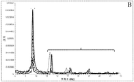
출원인의 가속도계는 왕복식 시험 장치의 사인곡선 패턴에 대한 반응에 대한 데이터를 수집하기 위해 3개의 주파수에서 평가되었다. 도 3a 및 도 3b는 FFT를 이용하여 주파수 영역으로 전환된 후의 수집된 데이터를 그래프로 표시한다.The applicant's accelerometer was evaluated at three frequencies to collect data on the response to the sinusoidal pattern of the reciprocal test device. FIGS. 3A and 3B graphically display the collected data after being converted to the frequency domain using the FFT.
이 주파수 영역 그래프는 2개의 가속도계에 의해 검출되는 주파수의 범위 및 이들의 상대 크기를 도시한다. MMA7361의 결과를 보여주는 도 3b와 출원인의 가속도계의 결과를 도시하고 있는 도 3a를 비교하면, 출원인의 가속도계는 원하는 주파수(기본 주파수)의 피크를 정확하게 하게 검출하여 양호하게 표시함을 알 수 있다. 도 3a의 데이터는 모든 센서가 중첩되도록, 그리고 6.28Hz의 공지된 주파수와 정렬되는 주파수 스케일로 작도되었다.This frequency domain graph shows the range of frequencies detected by the two accelerometers and their relative magnitudes. Comparing FIG. 3B, which shows the results of MMA 7361 with FIG. 3A, which shows the results of the applicant's accelerometer, the applicant's accelerometer accurately detects and displays the peak of the desired frequency (fundamental frequency) accurately. The data in Figure 3a was plotted with a frequency scale such that all the sensors were superimposed and aligned with a known frequency of 6.28 Hz.
도 3a는 5개의 상이한 PCB 트레이싱(tracing)의 각각에 대한 데이터를 열거하고 있다. 검출된 주파수 고조파의 수는 5개의 상이한 센서 디자인(210, 220, 230, 240, 250)에 대해 명확하게 다르다. Figure 3A lists data for each of five different PCB traces. The number of detected frequency harmonics is distinctly different for the five
도 3a는 왕복식 톱 시험 장치의 회전 성질의 결과인 고조파의 존재를 보여준다. 이러한 고조파는 일부의 용도를 위해 중요한 측정결과일 가능성이 있다. 출원인의 가속도계는 검출된 고조파에 대해 훨씬 더 높은 피크를 갖는 점에서 상용의 MMA7361 가속도계와 다르다. 출원인의 가속도계의 이러한 증가된 감도는 시스템 내에서 극히 작은 검출가능한 변화를 발생시키는 전도성 발포체의 높은 감도에 기인하는 것으로, 이러한 특징은 많은 용도, 특히 의료 분야에서 바람직할 수 있다.Figure 3a shows the presence of harmonics as a result of the rotational properties of the reciprocating saw testing apparatus. These harmonics may be important measurement results for some applications. Applicant's accelerometer differs from the commercial MMA 7361 accelerometer in that it has a much higher peak for the detected harmonics. This increased sensitivity of the applicant's accelerometer is due to the high sensitivity of the conductive foam to produce a very small detectable change in the system, which may be desirable in many applications, particularly in the medical field.
도 4a 및 도 4b는 8.35Hz의 시험에 대한 데이터를 도시하고 있다. 도 4a는 5개의 상이한 PCB 트레이싱의 각각에 대한 데이터를 열거하고 있다. 검출된 주파수 고조파의 수는 5개의 상이한 센서 디자인(210, 220, 230, 240, 250)에 대해 명확하게 다르다. Figures 4a and 4b show data for a test at 8.35 Hz. Figure 4A lists the data for each of the five different PCB traces. The number of detected frequency harmonics is distinctly different for the five
도 4a는 왕복식 톱 시험 장치의 회전 성질의 결과인 고조파의 존재를 보여준다. 이러한 고조파는 일부의 용도를 위해 중요한 측정결과일 가능성이 있다. 출원인의 가속도계는 검출된 고조파에 대해 훨씬 더 높은 피크를 갖는 점에서 상용의 MMA7361 가속도계와 다르다. 출원인의 가속도계의 이러한 증가된 감도는 시스템 내에서 극히 작은 검출가능한 변화를 발생시키는 전도성 발포체의 높은 감도에 기인하는 것으로, 이러한 특징은 많은 용도, 특히 의료 분야에서 바람직할 수 있다.Figure 4a shows the presence of harmonics as a result of the rotational properties of the reciprocating saw testing apparatus. These harmonics may be important measurement results for some applications. Applicant's accelerometer differs from the commercial MMA 7361 accelerometer in that it has a much higher peak for the detected harmonics. This increased sensitivity of the applicant's accelerometer is due to the high sensitivity of the conductive foam to produce a very small detectable change in the system, which may be desirable in many applications, particularly in the medical field.
도 5a는 11.00Hz의 시험에 대한 데이터를 열거하고 있다. 도 5a는 5개의 상이한 PCB 트레이싱의 각각에 대한 데이터를 열거하고 있다. 검출된 주파수 고조파의 수는 5개의 상이한 센서 디자인(210, 220, 230, 240, 250)에 대해 명확하게 다르다. Figure 5A lists the data for the 11.00 Hz test. Figure 5A lists the data for each of the five different PCB traces. The number of detected frequency harmonics is distinctly different for the five
도 5a는 왕복식 톱 시험 장치의 회전 성질의 결과인 고조파의 존재를 보여준다. 이러한 고조파는 일부의 용도를 위해 중요한 측정결과일 가능성이 있다. 출원인의 가속도계는 검출된 고조파에 대해 훨씬 더 높은 피크를 갖는 점에서 상용의 MMA7361 가속도계와 다르다. 출원인의 가속도계의 이러한 증가된 감도는 시스템 내에서 극히 작은 검출가능한 변화를 발생시키는 전도성 발포체의 높은 감도에 기인하는 것으로, 이러한 특징은 많은 용도, 특히 의료 분야에서 바람직할 수 있다.5A shows the presence of harmonics as a result of the rotational properties of the reciprocating saw testing apparatus. These harmonics may be important measurement results for some applications. Applicant's accelerometer differs from the commercial MMA 7361 accelerometer in that it has a much higher peak for the detected harmonics. This increased sensitivity of the applicant's accelerometer is due to the high sensitivity of the conductive foam to produce a very small detectable change in the system, which may be desirable in many applications, particularly in the medical field.
출원인의 가속도계의 주파수 영역 그래프인 도 3a, 도 4a, 및 도 5a에서 프리스케일 가속도계 그래프에서는 보이지 않는 수개의 추가의 피크가 존재한다. 이들 고조파는 시험 메커니즘의 자연적인 불균형으로 인해 유발되는 것으로서 몇 가지 원인에 의해 출원인의 가속도계의 그래프 상에 나타난다. There are several additional peaks that are not visible in the Freescale accelerometer graphs in Figures 3a, 4a, and 5a, which are frequency domain graphs of the applicant's accelerometer. These harmonics are caused by the natural imbalance of the test mechanism and appear on the graph of the applicant's accelerometer for several reasons.
출원인의 가속도계는 MMA7361 가속도계와 달리 이들 고조파를 제거하기 위해 실시되는 필터링 또는 처리 공정을 갖지 않는다. 발포체 가속도계와 MMA7361 가속도계 사이의 디자인 차이(거대 디자인 대 미소 디자인)도 또한 이들 고조파의 원인이다. 또한 검출 방법 및 전극의 디자인에 기인되어 고조파 왜곡이 발생될 수 있고, 이것은 부정 고조파(false harmonics)를 출현시키는 원인이 된다. 실제로, 이러한 이유들의 하나 이상을 조합할 수 있다.Applicants' accelerometers, unlike the MMA7361 accelerometer, do not have a filtering or processing process that is implemented to remove these harmonics. The design difference between the foam accelerometer and the MMA7361 accelerometer (large vs. small designs) is also the cause of these harmonics. In addition, harmonic distortion may occur due to the detection method and electrode design, which causes false harmonics to appear. Indeed, one or more of these reasons can be combined.
이하 도 6을 참조하면, 6.28Hz에서 시험된 출원인의 가속도계의 주파수 영역으로부터의 고조파 데이터가 고조파의 진폭과 0 내지 1의 척도로 비교된다. 여기서 각각의 센서의 제 1 바는 6.28Hz의 측정된 주파수를 나타내고, 후속의 바는 주파수 영역의 측정가능한 고조파를 나타낸다. 이 그래프에서 각각의 센서는 도 2에 도시된 바와 같은 상이한 전극 디자인에 대응된다. Referring now to FIG. 6, harmonic data from the applicant's accelerometer frequency domain tested at 6.28 Hz are compared with the amplitude of the harmonics and a scale of 0 to 1. Where the first bar of each sensor represents the measured frequency of 6.28 Hz and the following bar represents the measurable harmonics in the frequency domain. In this graph, each sensor corresponds to a different electrode design as shown in Fig.
이하 도 7을 참조하면, 8.35Hz에서 시험된 출원인의 가속도계의 주파수 영역으로부터의 고조파 데이터가 고조파의 진폭과 0 내지 1의 척도로 비교된다. 여기서 각각의 센서의 제 1 바는 8.35Hz의 측정된 주파수를 나타내고, 후속의 바는 주파수 영역의 측정가능한 고조파를 나타낸다. 이 그래프에서 각각의 센서는 도 2에 도시된 바와 같은 상이한 전극 디자인에 대응된다.Referring now to FIG. 7, harmonic data from the applicant's accelerometer frequency domain tested at 8.35 Hz are compared to the amplitude of the harmonics and to a scale of 0 to 1. Where the first bar of each sensor represents the measured frequency of 8.35 Hz and the subsequent bars represent the measurable harmonics in the frequency domain. In this graph, each sensor corresponds to a different electrode design as shown in Fig.
이하 도 8을 참조하면, 11.00Hz에서 시험된 출원인의 가속도계의 주파수 영역으로부터의 고조파 데이터가 고조파의 진폭과 0 내지 1의 척도로 비교된다. 여기서 각각의 센서의 제 1 바는 11.00Hz의 측정된 주파수를 나타내고, 후속의 바는 주파수 영역의 측정가능한 고조파를 나타낸다. 이 그래프에서 각각의 센서는 도 2에 도시된 바와 같은 상이한 전극 디자인에 대응된다.Referring now to FIG. 8, harmonic data from the frequency domain of the accelerometer of the applicant tested at 11.00 Hz are compared with the amplitude of the harmonics and a scale of 0 to 1. Where the first bar of each sensor represents the measured frequency of 11.00 Hz and the subsequent bars represent the measurable harmonics in the frequency domain. In this graph, each sensor corresponds to a different electrode design as shown in Fig.
도 6, 도 7, 및 도 8에 도시된 바와 같이, 단일의 전극 디자인이 고조파의 전부를 최소화하거나 최대화하지 않는다. 어떤 용도에서 특정의 주파수를 경험하는 경우, 다른 전극에 비해 하나의 전극 디자인을 고조파를 최소화하거나 증폭하기 위한 목적으로 사용하는 것이 바람직할 수 있다. 도 6에서, 센서(240)는 전체적으로 최저 진폭을 갖지만 도 8에서는 최대 진폭을 가지므로 이것은 더 낮은 주파수 및 최소 고조파 진폭용으로 선택되는 것이 더 유리하다. 마찬가지로, 센서(230)은 8.35Hz의 범위에서 고조파를 최소화하지만 6.28 내지 11Hz 범위의 양자 모두에서 고조파에 대한 감도를 증가시킨다. As shown in Figures 6, 7 and 8, a single electrode design does not minimize or maximize all of the harmonics. It may be desirable to use one electrode design for the purpose of minimizing or amplifying harmonics compared to other electrodes when experiencing a particular frequency in an application. In FIG. 6,
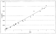
이하 도 9를 참조하면, 관련성을 결정하기 위해 전류의 양과 측정된 g-힘을 비교하였다. 도 9에 도시되어 있는 바와 같이, 증가되는 선형 관계가 발견되었고, 여기서 R2 값은 0.9669이다. 그래프 상의 더 조밀한 간격의 점들은 더 낮은 g-힘에서 힘과 전류 사이에 더 강한 상호관련이 존재함을 나타낸다. Referring now to Figure 9, the amount of current and the measured g-force are compared to determine the relevance. As shown in FIG. 9, an increasing linear relationship was found, where the R2 value is 0.9669. Denser spaced points on the graph indicate that there is a stronger correlation between force and current at the lower g-force.
결론:conclusion:
가속도계는 의료 분야에서 착용가능한 장치 및 이식가능한 장치의 양자 모두에서 중요한 역할을 유지한다. 운동선수, 군인, 및 심지어 고령 환자의 외상성 뇌손상의 검출은 실행가능한 해결책이 없는 점증하는 현안문제이다. 출원인의 가속도계는 다양한 형상 및 크기로 충격 및 가속력을 정확하게 검출하는 능력으로 이러한 문제에 대해 대처하기 위한 잠재력을 갖는다. Accelerometers play an important role in both wearable devices and implantable devices in the medical field. Detection of traumatic brain injury in athletes, soldiers, and even elderly patients is an increasing issue that lacks a viable solution. The applicant's accelerometer has the potential to cope with this problem with the ability to accurately detect shock and acceleration forces in a variety of shapes and sizes.
앞에서 설명한 바와 같이, 이 센서의 굴곡가능한 발포체 성질로 인해 이 가속도계는 기존의 헬멧의 내부, 손목 주위의 착용가능한 센서에 장착될 수 있거나, 심지어 소형화되어 이식가능한 장치의 내부에 장착될 수 있다. 검출 방법으로서 포텐쇼스탯을 사용하면 높은 감도 레벨이 보장되고, 특정의 전극 디자인과 조합된 각각의 가속도계는 특정의 용도에 맞춰질 수 있다. As described above, due to the flexible foam nature of the sensor, the accelerometer can be mounted inside a conventional helmet, on a wearable sensor around the wrist, or even down-sized and mounted inside the implantable device. Using a potentiostat as a detection method ensures a high sensitivity level, and each accelerometer combined with a specific electrode design can be tailored to a particular application.
본 발명의 바람직한 실시형태가 상세히 설명되었으나, 본 기술분야의 당업자는 본 명세서에서 설명된 바와 같은 본 발명의 범위로부터 벗어나지 않는 범위 내에서 이들 실시형태에 대한 개조 및 개작을 실시할 수 있다.While the preferred embodiments of the invention have been described in detail, those skilled in the art will be able to make modifications and adaptations to these embodiments without departing from the scope of the invention as described herein.
Claims (15)
제 1 부재 및 이동가능한 제 2 부재를 갖는 브래킷;
한 쌍의 전극;
제 1 도전성 발포체; 및
제 2 도전성 발포체를 포함하고,
상기 제 1 도전성 발포체 및 상기 제 2 도전성 발포체는 상기 한 쌍의 전극 및 상기 브래킷 사이에 삽입되는,
가속도계.As an accelerometer,
A bracket having a first member and a movable second member;
A pair of electrodes;
A first conductive foam; And
A second electrically conductive foam,
Wherein the first conductive foam and the second conductive foam are inserted between the pair of electrodes and the bracket,
Accelerometer.
인쇄 회로 보드는 상기 제 1 전극 및 상기 제 2 전극을 포함하는,
가속도계.The method according to claim 1,
The printed circuit board includes the first electrode and the second electrode.
Accelerometer.
상기 인쇄 회로 보드는 상기 제 2 전극과 인터리빙(interleaving)된 상기 제 1 전극을 포함하는,
가속도계.3. The method of claim 2,
Wherein the printed circuit board includes the first electrode interleaved with the second electrode.
Accelerometer.
상기 가속도계는 상기 제 1 도전성 발포체와 상기 제 2 도전성 발포체 사이에 배치되는 중량체를 더 포함하는,
가속도계.The method according to claim 1,
Wherein the accelerometer further comprises a weight disposed between the first conductive foam and the second conductive foam,
Accelerometer.
상기 가속도계는,
브래킷;
한 쌍의 전극;
제 1 도전성 발포체; 및
제 2 도전성 발포체를 포함하고,
상기 제 1 도전성 발포체 및 상기 제 2 도전성 발포체는 상기 한 쌍의 전극 및 상기 브래킷 사이에 삽입되는,
풋볼 헬멧.A football helmet with an accelerometer mounted therein,
The accelerometer,
Bracket;
A pair of electrodes;
A first conductive foam; And
A second electrically conductive foam,
Wherein the first conductive foam and the second conductive foam are inserted between the pair of electrodes and the bracket,
Football helmet.
인쇄 회로 보드는 상기 제 1 전극 및 상기 제 2 전극을 포함하는,
풋볼 헬멧.6. The method of claim 5,
The printed circuit board includes the first electrode and the second electrode.
Football helmet.
상기 인쇄 회로 보드는 상기 제 2 전극과 인터리빙된 상기 제 1 전극을 포함하는,
풋볼 헬멧.6. The method of claim 5,
Wherein the printed circuit board includes the first electrode interleaved with the second electrode,
Football helmet.
상기 풋볼 헬멧은 상기 제 1 도전성 발포체와 상기 제 2 도전성 발포체 사이에 배치되는 중량체를 더 포함하는,
풋볼 헬멧.6. The method of claim 5,
Wherein the football helmet further comprises a weight disposed between the first electrically conductive foam and the second electrically conductive foam.
Football helmet.
상기 가속도계는,
브래킷;
한 쌍의 전극;
제 1 도전성 발포체; 및
제 2 도전성 발포체를 포함하고,
상기 제 1 도전성 발포체 및 상기 제 2 도전성 발포체는 상기 한 쌍의 전극 및 상기 브래킷 사이에 삽입되는,
손목 밴드.A wristband comprising an accelerometer,
The accelerometer,
Bracket;
A pair of electrodes;
A first conductive foam; And
A second electrically conductive foam,
Wherein the first conductive foam and the second conductive foam are inserted between the pair of electrodes and the bracket,
Wrist band.
인쇄 회로 보드는 상기 제 1 전극 및 상기 제 2 전극을 포함하는,
풋볼 헬멧.10. The method of claim 9,
The printed circuit board includes the first electrode and the second electrode.
Football helmet.
상기 인쇄 회로 보드는 상기 제 2 전극과 인터리빙된 상기 제 1 전극을 포함하는,
풋볼 헬멧.11. The method of claim 10,
Wherein the printed circuit board includes the first electrode interleaved with the second electrode,
Football helmet.
상기 풋볼 헬멧은 상기 제 1 도전성 발포체와 상기 제 2 도전성 발포체 사이에 배치되는 중량체를 더 포함하는,
풋볼 헬멧.10. The method of claim 9,
Wherein the football helmet further comprises a weight disposed between the first electrically conductive foam and the second electrically conductive foam.
Football helmet.
브래킷, 한 쌍의 전극, 제 1 도전성 발포체, 제 2 도전성 발포체를 포함하는 가속도계를 제공하는 단계 - 상기 제 1 도전성 발포체 및 상기 제 2 도전성 발포체는 상기 한 쌍의 전극과 상기 브래킷 사이에 삽입됨 -;
대상물에 상기 가속도계를 부착하는 단계;
힘으로 상기 대상물/가속도계 어셈블리에 충격을 가하는 단계;
상기 충격 중에 발생되는 전류를 측정하는 단계; 및
상기 측정된 전류에 기초하여 G 힘 충격을 결정하는 단계를 포함하는,
충격력 측정 방법.As a method for measuring an impact force,
Providing an accelerometer comprising a bracket, a pair of electrodes, a first conductive foam, and a second conductive foam, the first conductive foam and the second conductive foam being inserted between the pair of electrodes and the bracket, ;
Attaching the accelerometer to an object;
Impacting the object / accelerometer assembly with force;
Measuring a current generated during the impact; And
And determining a G force impulse based on the measured current.
Impact force measurement method.
인쇄 회로 보드는 상기 제 1 전극 및 상기 제 2 전극을 포함하는,
충격력 측정 방법.14. The method of claim 13,
The printed circuit board includes the first electrode and the second electrode.
Impact force measurement method.
상기 인쇄 회로 보드는 상기 제 2 전극과 인터리빙된 상기 제 1 전극을 포함하는,
충격력 측정 방법.15. The method of claim 14,
Wherein the printed circuit board includes the first electrode interleaved with the second electrode,
Impact force measurement method.
Applications Claiming Priority (3)
| Application Number | Priority Date | Filing Date | Title |
|---|---|---|---|
| US201462029176P | 2014-07-25 | 2014-07-25 | |
| US62/029,176 | 2014-07-25 | ||
| PCT/US2015/041386 WO2016014572A1 (en) | 2014-07-25 | 2015-07-21 | Acceleration-sensing electrochemical pressure sensor compositions |
Publications (1)
| Publication Number | Publication Date |
|---|---|
| KR20170036065A true KR20170036065A (en) | 2017-03-31 |
Family
ID=55163650
Family Applications (1)
| Application Number | Title | Priority Date | Filing Date |
|---|---|---|---|
| KR1020177005311A KR20170036065A (en) | 2014-07-25 | 2015-07-21 | Acceleration-sensing electrochemical pressure sensor compositions |
Country Status (6)
| Country | Link |
|---|---|
| US (1) | US9909942B2 (en) |
| EP (1) | EP3172773A4 (en) |
| JP (1) | JP2017527825A (en) |
| KR (1) | KR20170036065A (en) |
| CA (1) | CA2956523A1 (en) |
| WO (1) | WO2016014572A1 (en) |
Families Citing this family (9)
| Publication number | Priority date | Publication date | Assignee | Title |
|---|---|---|---|---|
| WO2012009322A1 (en) | 2010-07-12 | 2012-01-19 | Arizona Board Of Regents, A Body Corporate Of The State Of Arizona, Acting For And On Behalf Of Arizona State University | Methods and device for tuning multiplexed markers for disease assay |
| US10323008B2 (en) | 2014-06-06 | 2019-06-18 | Arizona Board Of Regents On Behalf Of Arizona State University | Unique self-assembled poly-amidoamine polymers and their electrochemical reactivity |
| EP3180618B1 (en) | 2014-08-13 | 2022-01-26 | Arizona Board of Regents on behalf of Arizona State University | Noninvasive body fluid stress sensing |
| WO2018067626A1 (en) | 2016-10-04 | 2018-04-12 | Arizona Board Of Regents On Behalf Of Arizona State University | Flexible sensors incorporating piezoresistive composite materials and fabrication methods |
| JP2018189438A (en) * | 2017-04-28 | 2018-11-29 | 北川工業株式会社 | Pressure sensitive sensor |
| US11331019B2 (en) | 2017-08-07 | 2022-05-17 | The Research Foundation For The State University Of New York | Nanoparticle sensor having a nanofibrous membrane scaffold |
| PL234977B1 (en) * | 2017-10-11 | 2020-05-18 | Bioengineering Spolka Z Ograniczona Odpowiedzialnoscia | Control system of a prosthesis and the prosthetic system equipped with the prosthesis control system installed in the footwear |
| WO2019147978A1 (en) | 2018-01-26 | 2019-08-01 | Arizona Board of Regents of behalf of Arizona State University | Wearable optical sensor for respiratory rate monitoring |
| US11173057B2 (en) | 2018-11-30 | 2021-11-16 | Arizona Board Of Regents On Behalf Of Arizona State University | Volume adjustable transtibial socket |
Family Cites Families (15)
| Publication number | Priority date | Publication date | Assignee | Title |
|---|---|---|---|---|
| US3996922A (en) * | 1973-08-17 | 1976-12-14 | Electronic Monitors, Inc. | Flexible force responsive transducer |
| JPH0537728Y2 (en) * | 1987-01-21 | 1993-09-24 | ||
| US6529122B1 (en) * | 1999-12-10 | 2003-03-04 | Siemens Technology-To-Business Center, Llc | Tactile sensor apparatus and methods |
| DE10232053A1 (en) * | 2002-07-16 | 2004-02-05 | Robert Bosch Gmbh | Motor vehicle impact sensor, especially suited to detection of an impact with a pedestrian, comprises foam whose conductivity changes when compressed and that is integrated into the vehicle bumper or bodywork |
| TWI255341B (en) * | 2004-06-10 | 2006-05-21 | Chung Shan Inst Of Science | Miniature accelerator |
| US7426861B2 (en) * | 2005-06-15 | 2008-09-23 | The Charles Stark Draper Laboratory, Inc. | Tuning fork gyroscopes, accelerometers, and other sensors with improved scale factor |
| US20070034007A1 (en) * | 2005-08-12 | 2007-02-15 | Cenk Acar | Multi-axis micromachined accelerometer |
| NZ551819A (en) * | 2006-12-04 | 2009-03-31 | Zephyr Technology Ltd | Impact detection system |
| JP2011505015A (en) * | 2007-11-27 | 2011-02-17 | 24エイト エルエルシー | System, method and computer program product for measuring pressure points |
| US20100152619A1 (en) * | 2008-12-16 | 2010-06-17 | 24/8 Llc | System, method, and computer-program product for measuring pressure points |
| FR2940904B1 (en) * | 2009-01-13 | 2012-08-31 | Urgo Laboratoires | INTERFACE PRESSURE MEASURING SYSTEM |
| US8120232B2 (en) * | 2009-01-20 | 2012-02-21 | Palo Alto Research Center Incorporated | Sensors and actuators using piezo polymer layers |
| US20100277328A1 (en) * | 2009-05-04 | 2010-11-04 | Mullan Deborah D | Force-sensitive presence detectors and methods of detecting presence |
| US8596147B2 (en) * | 2010-11-30 | 2013-12-03 | Hallmark Cards, Incorporated | Non-rigid sensor for detecting deformation |
| WO2014100045A1 (en) * | 2012-12-17 | 2014-06-26 | Qi2 ELEMENTS II, LLC | Foot-mounted sensor systems for tracking body movement |
-
2015
- 2015-07-21 JP JP2017525301A patent/JP2017527825A/en active Pending
- 2015-07-21 WO PCT/US2015/041386 patent/WO2016014572A1/en active Application Filing
- 2015-07-21 CA CA2956523A patent/CA2956523A1/en not_active Abandoned
- 2015-07-21 EP EP15824712.2A patent/EP3172773A4/en not_active Withdrawn
- 2015-07-21 KR KR1020177005311A patent/KR20170036065A/en unknown
-
2017
- 2017-01-24 US US15/414,238 patent/US9909942B2/en active Active
Also Published As
| Publication number | Publication date |
|---|---|
| JP2017527825A (en) | 2017-09-21 |
| EP3172773A4 (en) | 2018-03-14 |
| US20170131163A1 (en) | 2017-05-11 |
| EP3172773A1 (en) | 2017-05-31 |
| WO2016014572A1 (en) | 2016-01-28 |
| CA2956523A1 (en) | 2016-01-28 |
| US9909942B2 (en) | 2018-03-06 |
Similar Documents
| Publication | Publication Date | Title |
|---|---|---|
| US9909942B2 (en) | Acceleration-sensing electrochemical pressure sensor compositions | |
| US20240044728A1 (en) | Negative poisson ratio piezoresistive sensor and method of manufacture | |
| Beckham et al. | Force plate use in performance monitoring and sport science testing | |
| EP2632327B1 (en) | A method and a device for measuring muscle signals | |
| Gilchrist et al. | Development of an inertia-driven model of sideways fall for detailed study of femur fracture mechanics | |
| HK1107242A1 (en) | Methods and device for the evaluation of muscular capacity of athletes with short tests | |
| Tarabini et al. | The potential of micro-electro-mechanical accelerometers in human vibration measurements | |
| Burkhart et al. | Determining the optimal system-specific cut-off frequencies for filtering in-vitro upper extremity impact force and acceleration data by residual analysis | |
| KR20170139645A (en) | Indicators, wearable devices and mobile devices | |
| WO2017213066A1 (en) | Tremor detection device, stress evaluation system using same, and stress evaluation method | |
| Jones et al. | Surface waves and spatial localization in vibrotactile displays | |
| Jack et al. | Validation of the Vicon 460 Motion Capture System™ for whole-body vibration acceleration determination | |
| Carlson et al. | Evidence of reliability and validity for the use of a helmet impact drop system | |
| RU156046U1 (en) | VIBRATION SIGNAL SPECTRUM ANALYZER | |
| Sundet et al. | Smartfoam Based Pressure Mapping | |
| Psota et al. | Mechanical testing of PCB using computer simulations | |
| Naves et al. | Design and evaluation of a biomechanical system for athletes performance analysis | |
| Provot et al. | Instrumentation for Mechanical Vibration Analysis | |
| WO2002094091A1 (en) | Fatigue inspection device and fatigue evaluation method | |
| CN216777065U (en) | Human body composition analyzer | |
| Provot et al. | 1 InstrumentationforMechanical | |
| US20220155160A1 (en) | Sensor Apparatus | |
| Singh et al. | Wearable Exercise Protocol Monitoring System for Athletic Training | |
| Ahn | Design and testing of [a] vibratory force measurement system for hand-arm vibration applications | |
| Ali et al. | Evaluating instrumented Charpy impact strain signals using curve fitting equations |