KR20170033296A - Method and apparatus for adjustable coupling for improved wireless high q resonant power transfer - Google Patents
Method and apparatus for adjustable coupling for improved wireless high q resonant power transfer Download PDFInfo
- Publication number
- KR20170033296A KR20170033296A KR1020177000835A KR20177000835A KR20170033296A KR 20170033296 A KR20170033296 A KR 20170033296A KR 1020177000835 A KR1020177000835 A KR 1020177000835A KR 20177000835 A KR20177000835 A KR 20177000835A KR 20170033296 A KR20170033296 A KR 20170033296A
- Authority
- KR
- South Korea
- Prior art keywords
- coupling
- resonator
- amount
- power
- load
- Prior art date
Links
- 238000010168 coupling process Methods 0.000 title claims abstract description 386
- 238000005859 coupling reaction Methods 0.000 title claims abstract description 386
- 230000008878 coupling Effects 0.000 title claims abstract description 381
- 238000000034 method Methods 0.000 title claims abstract description 78
- 238000012546 transfer Methods 0.000 title description 9
- 230000005540 biological transmission Effects 0.000 claims abstract description 51
- 230000001939 inductive effect Effects 0.000 claims abstract description 41
- 239000003990 capacitor Substances 0.000 claims description 61
- 230000005291 magnetic effect Effects 0.000 description 47
- 230000004044 response Effects 0.000 description 33
- 238000010586 diagram Methods 0.000 description 31
- 238000004891 communication Methods 0.000 description 30
- 238000000926 separation method Methods 0.000 description 30
- 230000004907 flux Effects 0.000 description 17
- 230000005855 radiation Effects 0.000 description 16
- 230000009471 action Effects 0.000 description 12
- 230000006870 function Effects 0.000 description 11
- 230000005684 electric field Effects 0.000 description 10
- 230000008901 benefit Effects 0.000 description 7
- 230000001965 increasing effect Effects 0.000 description 7
- 238000004364 calculation method Methods 0.000 description 6
- 230000002500 effect on skin Effects 0.000 description 6
- 238000005259 measurement Methods 0.000 description 6
- 238000001228 spectrum Methods 0.000 description 6
- 238000012360 testing method Methods 0.000 description 6
- 230000007423 decrease Effects 0.000 description 5
- 230000010355 oscillation Effects 0.000 description 5
- 239000000243 solution Substances 0.000 description 5
- XEEYBQQBJWHFJM-UHFFFAOYSA-N Iron Chemical compound [Fe] XEEYBQQBJWHFJM-UHFFFAOYSA-N 0.000 description 4
- 239000004020 conductor Substances 0.000 description 4
- 239000011162 core material Substances 0.000 description 4
- 238000013461 design Methods 0.000 description 4
- 238000004146 energy storage Methods 0.000 description 4
- 230000007704 transition Effects 0.000 description 3
- 238000004804 winding Methods 0.000 description 3
- RYGMFSIKBFXOCR-UHFFFAOYSA-N Copper Chemical compound [Cu] RYGMFSIKBFXOCR-UHFFFAOYSA-N 0.000 description 2
- 238000004422 calculation algorithm Methods 0.000 description 2
- 230000001419 dependent effect Effects 0.000 description 2
- 230000000694 effects Effects 0.000 description 2
- 230000005672 electromagnetic field Effects 0.000 description 2
- 230000006698 induction Effects 0.000 description 2
- 239000012212 insulator Substances 0.000 description 2
- 229910052742 iron Inorganic materials 0.000 description 2
- 230000007935 neutral effect Effects 0.000 description 2
- 230000003287 optical effect Effects 0.000 description 2
- 238000005457 optimization Methods 0.000 description 2
- 239000002245 particle Substances 0.000 description 2
- 238000010079 rubber tapping Methods 0.000 description 2
- 230000005236 sound signal Effects 0.000 description 2
- 238000010408 sweeping Methods 0.000 description 2
- 241000282816 Giraffa camelopardalis Species 0.000 description 1
- 238000003915 air pollution Methods 0.000 description 1
- 238000013459 approach Methods 0.000 description 1
- 230000002238 attenuated effect Effects 0.000 description 1
- 230000015556 catabolic process Effects 0.000 description 1
- 230000008859 change Effects 0.000 description 1
- 239000012141 concentrate Substances 0.000 description 1
- 238000013016 damping Methods 0.000 description 1
- 238000006731 degradation reaction Methods 0.000 description 1
- 239000003989 dielectric material Substances 0.000 description 1
- 230000005674 electromagnetic induction Effects 0.000 description 1
- 238000002474 experimental method Methods 0.000 description 1
- 238000000605 extraction Methods 0.000 description 1
- 239000003302 ferromagnetic material Substances 0.000 description 1
- 239000000945 filler Substances 0.000 description 1
- 238000001914 filtration Methods 0.000 description 1
- 239000002803 fossil fuel Substances 0.000 description 1
- 238000010438 heat treatment Methods 0.000 description 1
- 238000002347 injection Methods 0.000 description 1
- 239000007924 injection Substances 0.000 description 1
- 230000005415 magnetization Effects 0.000 description 1
- 239000000463 material Substances 0.000 description 1
- 230000007246 mechanism Effects 0.000 description 1
- 238000012986 modification Methods 0.000 description 1
- 230000004048 modification Effects 0.000 description 1
- 230000035515 penetration Effects 0.000 description 1
- 230000010363 phase shift Effects 0.000 description 1
- 230000021715 photosynthesis, light harvesting Effects 0.000 description 1
- 238000005381 potential energy Methods 0.000 description 1
- 230000001902 propagating effect Effects 0.000 description 1
- 230000000087 stabilizing effect Effects 0.000 description 1
- 230000001360 synchronised effect Effects 0.000 description 1
- 238000012800 visualization Methods 0.000 description 1
- 229910000859 α-Fe Inorganic materials 0.000 description 1
Images


Classifications
-
- B60L11/182—
-
- B—PERFORMING OPERATIONS; TRANSPORTING
- B60—VEHICLES IN GENERAL
- B60L—PROPULSION OF ELECTRICALLY-PROPELLED VEHICLES; SUPPLYING ELECTRIC POWER FOR AUXILIARY EQUIPMENT OF ELECTRICALLY-PROPELLED VEHICLES; ELECTRODYNAMIC BRAKE SYSTEMS FOR VEHICLES IN GENERAL; MAGNETIC SUSPENSION OR LEVITATION FOR VEHICLES; MONITORING OPERATING VARIABLES OF ELECTRICALLY-PROPELLED VEHICLES; ELECTRIC SAFETY DEVICES FOR ELECTRICALLY-PROPELLED VEHICLES
- B60L53/00—Methods of charging batteries, specially adapted for electric vehicles; Charging stations or on-board charging equipment therefor; Exchange of energy storage elements in electric vehicles
- B60L53/10—Methods of charging batteries, specially adapted for electric vehicles; Charging stations or on-board charging equipment therefor; Exchange of energy storage elements in electric vehicles characterised by the energy transfer between the charging station and the vehicle
- B60L53/12—Inductive energy transfer
- B60L53/122—Circuits or methods for driving the primary coil, e.g. supplying electric power to the coil
-
- B—PERFORMING OPERATIONS; TRANSPORTING
- B60—VEHICLES IN GENERAL
- B60L—PROPULSION OF ELECTRICALLY-PROPELLED VEHICLES; SUPPLYING ELECTRIC POWER FOR AUXILIARY EQUIPMENT OF ELECTRICALLY-PROPELLED VEHICLES; ELECTRODYNAMIC BRAKE SYSTEMS FOR VEHICLES IN GENERAL; MAGNETIC SUSPENSION OR LEVITATION FOR VEHICLES; MONITORING OPERATING VARIABLES OF ELECTRICALLY-PROPELLED VEHICLES; ELECTRIC SAFETY DEVICES FOR ELECTRICALLY-PROPELLED VEHICLES
- B60L53/00—Methods of charging batteries, specially adapted for electric vehicles; Charging stations or on-board charging equipment therefor; Exchange of energy storage elements in electric vehicles
- B60L53/10—Methods of charging batteries, specially adapted for electric vehicles; Charging stations or on-board charging equipment therefor; Exchange of energy storage elements in electric vehicles characterised by the energy transfer between the charging station and the vehicle
- B60L53/12—Inductive energy transfer
- B60L53/126—Methods for pairing a vehicle and a charging station, e.g. establishing a one-to-one relation between a wireless power transmitter and a wireless power receiver
-
- B—PERFORMING OPERATIONS; TRANSPORTING
- B60—VEHICLES IN GENERAL
- B60L—PROPULSION OF ELECTRICALLY-PROPELLED VEHICLES; SUPPLYING ELECTRIC POWER FOR AUXILIARY EQUIPMENT OF ELECTRICALLY-PROPELLED VEHICLES; ELECTRODYNAMIC BRAKE SYSTEMS FOR VEHICLES IN GENERAL; MAGNETIC SUSPENSION OR LEVITATION FOR VEHICLES; MONITORING OPERATING VARIABLES OF ELECTRICALLY-PROPELLED VEHICLES; ELECTRIC SAFETY DEVICES FOR ELECTRICALLY-PROPELLED VEHICLES
- B60L53/00—Methods of charging batteries, specially adapted for electric vehicles; Charging stations or on-board charging equipment therefor; Exchange of energy storage elements in electric vehicles
- B60L53/30—Constructional details of charging stations
-
- H—ELECTRICITY
- H01—ELECTRIC ELEMENTS
- H01F—MAGNETS; INDUCTANCES; TRANSFORMERS; SELECTION OF MATERIALS FOR THEIR MAGNETIC PROPERTIES
- H01F38/00—Adaptations of transformers or inductances for specific applications or functions
- H01F38/14—Inductive couplings
-
- H02J5/005—
-
- H—ELECTRICITY
- H02—GENERATION; CONVERSION OR DISTRIBUTION OF ELECTRIC POWER
- H02J—CIRCUIT ARRANGEMENTS OR SYSTEMS FOR SUPPLYING OR DISTRIBUTING ELECTRIC POWER; SYSTEMS FOR STORING ELECTRIC ENERGY
- H02J50/00—Circuit arrangements or systems for wireless supply or distribution of electric power
- H02J50/005—Mechanical details of housing or structure aiming to accommodate the power transfer means, e.g. mechanical integration of coils, antennas or transducers into emitting or receiving devices
-
- H—ELECTRICITY
- H02—GENERATION; CONVERSION OR DISTRIBUTION OF ELECTRIC POWER
- H02J—CIRCUIT ARRANGEMENTS OR SYSTEMS FOR SUPPLYING OR DISTRIBUTING ELECTRIC POWER; SYSTEMS FOR STORING ELECTRIC ENERGY
- H02J50/00—Circuit arrangements or systems for wireless supply or distribution of electric power
- H02J50/10—Circuit arrangements or systems for wireless supply or distribution of electric power using inductive coupling
- H02J50/12—Circuit arrangements or systems for wireless supply or distribution of electric power using inductive coupling of the resonant type
-
- H—ELECTRICITY
- H02—GENERATION; CONVERSION OR DISTRIBUTION OF ELECTRIC POWER
- H02J—CIRCUIT ARRANGEMENTS OR SYSTEMS FOR SUPPLYING OR DISTRIBUTING ELECTRIC POWER; SYSTEMS FOR STORING ELECTRIC ENERGY
- H02J50/00—Circuit arrangements or systems for wireless supply or distribution of electric power
- H02J50/80—Circuit arrangements or systems for wireless supply or distribution of electric power involving the exchange of data, concerning supply or distribution of electric power, between transmitting devices and receiving devices
-
- H02J7/025—
-
- H—ELECTRICITY
- H04—ELECTRIC COMMUNICATION TECHNIQUE
- H04B—TRANSMISSION
- H04B5/00—Near-field transmission systems, e.g. inductive loop type
- H04B5/0025—Near field system adaptations
- H04B5/0037—Near field system adaptations for power transfer
-
- H04B5/24—
-
- H04B5/79—
-
- H—ELECTRICITY
- H03—ELECTRONIC CIRCUITRY
- H03J—TUNING RESONANT CIRCUITS; SELECTING RESONANT CIRCUITS
- H03J2200/00—Indexing scheme relating to tuning resonant circuits and selecting resonant circuits
- H03J2200/35—Inductance tunable by switching in/out parts of the inductor
-
- Y—GENERAL TAGGING OF NEW TECHNOLOGICAL DEVELOPMENTS; GENERAL TAGGING OF CROSS-SECTIONAL TECHNOLOGIES SPANNING OVER SEVERAL SECTIONS OF THE IPC; TECHNICAL SUBJECTS COVERED BY FORMER USPC CROSS-REFERENCE ART COLLECTIONS [XRACs] AND DIGESTS
- Y02—TECHNOLOGIES OR APPLICATIONS FOR MITIGATION OR ADAPTATION AGAINST CLIMATE CHANGE
- Y02T—CLIMATE CHANGE MITIGATION TECHNOLOGIES RELATED TO TRANSPORTATION
- Y02T10/00—Road transport of goods or passengers
- Y02T10/60—Other road transportation technologies with climate change mitigation effect
- Y02T10/70—Energy storage systems for electromobility, e.g. batteries
-
- Y—GENERAL TAGGING OF NEW TECHNOLOGICAL DEVELOPMENTS; GENERAL TAGGING OF CROSS-SECTIONAL TECHNOLOGIES SPANNING OVER SEVERAL SECTIONS OF THE IPC; TECHNICAL SUBJECTS COVERED BY FORMER USPC CROSS-REFERENCE ART COLLECTIONS [XRACs] AND DIGESTS
- Y02—TECHNOLOGIES OR APPLICATIONS FOR MITIGATION OR ADAPTATION AGAINST CLIMATE CHANGE
- Y02T—CLIMATE CHANGE MITIGATION TECHNOLOGIES RELATED TO TRANSPORTATION
- Y02T10/00—Road transport of goods or passengers
- Y02T10/60—Other road transportation technologies with climate change mitigation effect
- Y02T10/7072—Electromobility specific charging systems or methods for batteries, ultracapacitors, supercapacitors or double-layer capacitors
-
- Y—GENERAL TAGGING OF NEW TECHNOLOGICAL DEVELOPMENTS; GENERAL TAGGING OF CROSS-SECTIONAL TECHNOLOGIES SPANNING OVER SEVERAL SECTIONS OF THE IPC; TECHNICAL SUBJECTS COVERED BY FORMER USPC CROSS-REFERENCE ART COLLECTIONS [XRACs] AND DIGESTS
- Y02—TECHNOLOGIES OR APPLICATIONS FOR MITIGATION OR ADAPTATION AGAINST CLIMATE CHANGE
- Y02T—CLIMATE CHANGE MITIGATION TECHNOLOGIES RELATED TO TRANSPORTATION
- Y02T90/00—Enabling technologies or technologies with a potential or indirect contribution to GHG emissions mitigation
- Y02T90/10—Technologies relating to charging of electric vehicles
- Y02T90/12—Electric charging stations
-
- Y—GENERAL TAGGING OF NEW TECHNOLOGICAL DEVELOPMENTS; GENERAL TAGGING OF CROSS-SECTIONAL TECHNOLOGIES SPANNING OVER SEVERAL SECTIONS OF THE IPC; TECHNICAL SUBJECTS COVERED BY FORMER USPC CROSS-REFERENCE ART COLLECTIONS [XRACs] AND DIGESTS
- Y02—TECHNOLOGIES OR APPLICATIONS FOR MITIGATION OR ADAPTATION AGAINST CLIMATE CHANGE
- Y02T—CLIMATE CHANGE MITIGATION TECHNOLOGIES RELATED TO TRANSPORTATION
- Y02T90/00—Enabling technologies or technologies with a potential or indirect contribution to GHG emissions mitigation
- Y02T90/10—Technologies relating to charging of electric vehicles
- Y02T90/14—Plug-in electric vehicles
Abstract
무선 유도성 전력 전송을 위한 방법들 및 장치들이 본 명세서에서 설명된다. 하나의 구현은 무선 유도성 전력 전송을 위한 장치를 포함할 수도 있다. 장치는 무선 전력 수신기의 로드에 커플링된 2 차 공진기에 전력을 무선으로 송신하도록 구성된 1 차 공진기를 포함한다. 장치는 1 차 공진기에 소스 전력 공급기로부터의 에너지를 커플링하도록 구성된 커플링 회로를 포함한다. 장치는 2 차 공진기와 무선 전력 수신기의 로드 사이의 커플링의 제 2 양의 조정과, 커플링 회로를 통한, 소스 전력 공급기와 1 차 공진기 사이의 커플링의 제 1 양의 조정을 코디네이션하도록 구성된 제어기를 포함한다. 커플링 회로는, 각각이 소스 전력 공급기에 선택적으로 전기적으로 연결되도록 구성되는, 복수의 세그먼트들을 포함하는 제 1 커플링 루프를 포함하고, 제 1 커플링 루프는 1 차 공진기로부터 전기적으로 격리된다.Methods and apparatus for wireless inductive power transmission are described herein. One implementation may include an apparatus for wireless inductive power transmission. The apparatus includes a primary resonator configured to wirelessly transmit power to a secondary resonator coupled to a load of the wireless power receiver. The apparatus includes a coupling circuit configured to couple energy from the source power supply to the primary resonator. The apparatus is configured to coordinate a second amount of coupling between the second resonator and the load of the wireless power receiver and to coordinate the adjustment of the first amount of coupling between the source power supply and the first resonator through the coupling circuit Controller. The coupling circuit includes a first coupling loop comprising a plurality of segments each of which is configured to be selectively electrically connected to the source power supply, wherein the first coupling loop is electrically isolated from the first resonator.

Description
설명된 기술은 일반적으로 무선 전력에 관한 것이다. 보다 구체적으로, 본 개시는 개선된 무선 고 Q 공진 전력 전송을 위해 조정가능한 커플링을 위한 방법들 및 장치들에 관련된다.The techniques described generally relate to wireless power. More particularly, this disclosure relates to methods and apparatus for tunable coupling for improved radio, high Q resonant power transmission.
현대의 휴대용 전자 디바이스들은 더 낮은 전력을 소비하면서 보다 고성능 배터리 전력 소스들을 포함하여, 보다 유능해졌다. 이 향상된 능력 및 항시 이용할 수 있는 상태 (always-on availability) 로 인해, 소비자들은 온갖 종류의 태스크들을 위해 휴대용 전자 디바이스들 (예를 들어, 전화기들 및 컴퓨터들) 에 의존하게 되었다. 소비자들은 디바이스들의 지속적인 이용가능성에 익숙해졌기 때문에, 연관된 배터리들이 무선으로 재충전가능한 것이 바람직하다. 유도성 무선 전력 전송이 무선 전력을 제공하기 위한 선호된 솔루션이 되었다. 유사하게, 배터리 전력공급된 전기 차량들은 증가하는 대기 오염의 수준과 화석 연료의 고갈에 대응하기 위한 솔루션으로서 더욱 인기를 끌고 있다. 전기 차량들의 추가 시장 침투에 대한 하나의 장애물은 그 차량에 과중한 전력 케이블을 일상적으로 연결하는 요건이다. 유도성 전력 전송에 의한 무선 충전은 정지 충전을 위한 선호된 솔루션이고 온더고 (on-the-go) 충전을 위한 유일한 솔루션이다. 유도성 전력 전송은 전력 송신기 및 전력 수신기에서의 공진 커플링된 인덕터들에 의해 개선된다. 추가로, 고도 공진 인덕터들은 더 장거리에 걸쳐 전력을 커플링하고 조금 더 효율적으로 하는 것이 가능하다. 이에 따라, 개선된 무선 고도 공진 유도성 전력 전송을 위해 조정가능한 커플링을 위한 방법들 및 장치들이 요망된다.Modern portable electronic devices have become more capable, including higher power battery power sources, while consuming lower power. With this improved capability and always-on availability, consumers have become dependent on portable electronic devices (e.g., phones and computers) for all sorts of tasks. Since consumers have become accustomed to the continued availability of devices, it is desirable that the associated batteries be rechargeable wirelessly. Inductive wireless power transmission has become the preferred solution for providing wireless power. Similarly, battery-powered electric vehicles are becoming more popular as a solution to cope with increasing levels of air pollution and depletion of fossil fuels. One obstacle to the further market penetration of electric vehicles is the requirement to routinely connect heavy power cables to the vehicle. Wireless charging with inductive power transmission is the preferred solution for stationary charging and is the only solution for on-the-go charging. The inductive power transmission is improved by the resonant coupled inductors in the power transmitter and power receiver. In addition, highly resonant inductors can couple power over longer distances and make them more efficient. Accordingly, there is a need for methods and apparatus for tunable coupling for improved wireless highly resonant inductive power transmission.
무선 유도성 전력 전송을 위한 장치가 제공된다. 장치는 무선 전력 수신기의 로드 (load) 에 커플링된 2 차 공진기에 전력을 무선으로 전송하도록 구성된 1 차 공진기를 포함한다. 장치는 1 차 공진기에 소스 전력 공급기로부터의 에너지를 커플링하도록 구성된 커플링 회로를 포함한다. 장치는 2 차 공진기와 무선 전력 수신기의 로드 사이의 커플링의 제 2 양의 조정과, 커플링 회로를 통한, 소스 전력 공급기와 1 차 공진기 사이의 커플링의 제 1 양의 조정을 코디네이션 (coordination) 하도록 구성된 제어기를 포함한다.An apparatus for wireless inductive power transmission is provided. The apparatus includes a primary resonator configured to wirelessly transmit power to a secondary resonator coupled to a load of the wireless power receiver. The apparatus includes a coupling circuit configured to couple energy from the source power supply to the primary resonator. The apparatus includes coordinating a second amount of coupling between the second resonator and the load of the wireless power receiver and adjusting a first amount of coupling between the source power supply and the first resonator through the coupling circuit, ).
무선 유도성 전력 전송을 위한 방법이 제공된다. 방법은 무선 전력 수신기의 로드에 커플링된 2 차 공진기에 무선 전력 송신기의 1 차 공진기로부터의 전력을 무선으로 전송하는 단계를 포함한다. 방법은 1 차 공진기에 소스 전력 공급기로부터의 에너지를 커플링하도록 구성된 커플링 회로를 통해 소스 전력 공급기와 1 차 공진기 사이의 커플링의 제 1 양을 조정하는 단계를 포함하고, 커플링의 제 1 양을 조정하는 단계는 2 차 공진기와 로드 사이의 커플링의 제 2 양의 조정과 코디네이션된다.A method for wireless inductive power transmission is provided. The method includes wirelessly transmitting power from a primary resonator of a wireless power transmitter to a secondary resonator coupled to a load of the wireless power receiver. The method includes adjusting a first amount of coupling between the source power supply and the primary resonator through a coupling circuit configured to couple energy from the source power supply to the primary resonator, The step of adjusting the amount is coordinated with the adjustment of the second amount of coupling between the secondary resonator and the rod.
무선 유도성 전력 전송을 위한 장치가 제공된다. 장치는 전력을 무선으로 수신하는 수단에 전력을 무선으로 전송하도록 구성된 무선장을 생성하는 수단을 포함하고, 전력을 무선으로 수신하는 수단은 무선 전력 수신기의 로드에 커플링된다. 장치는 무선장을 생성하는 수단에 전력 소스 공급기로부터의 에너지를 커플링하는 수단을 포함한다. 장치는 전력을 무선으로 수신하는 수단과 무선 전력 수신기의 로드 사이의 커플링의 제 2 양의 조정과, 에너지를 커플링하는 수단을 통한, 소스 전력 공급기와 무선장을 생성하는 수단 사이의 커플링의 제 1 양의 조정을 코디네이션하는 수단을 포함한다.An apparatus for wireless inductive power transmission is provided. The apparatus includes means for generating a wireless field configured to wirelessly transmit power to a means for wirelessly receiving power, and means for wirelessly receiving power is coupled to a load of the wireless power receiver. The apparatus includes means for coupling energy from the power source supply to the means for generating the wireless field. The apparatus comprises a coupling between the means for wirelessly receiving power and the second amount of coupling between the load of the wireless power receiver and the means for generating the wireless field by means of coupling the energy, And means for coordinating the adjustment of the first amount of the first quantity.
무선 전력을 유도적으로 수신하기 위한 장치가 제공된다. 장치는 무선 전력 송신기의 1 차 공진기로부터 전력을 무선으로 수신하도록 구성된 2 차 공진기를 포함한다. 장치는 로드에 2 차 공진기로부터의 에너지를 커플링하도록 구성된 커플링 회로를 포함한다. 장치는 소스 전력 공급기와 무선 전력 송신기의 1 차 공진기 사이의 커플링의 제 1 양의 조정과, 커플링 회로를 통한, 2 차 공진기와 로드 사이의 커플링의 제 2 양의 조정을 코디네이션하도록 구성된 제어기를 포함한다.An apparatus for inductively receiving wireless power is provided. The apparatus includes a secondary resonator configured to wirelessly receive power from a primary resonator of the wireless power transmitter. The apparatus includes a coupling circuit configured to couple energy from the secondary resonator to the load. The apparatus is configured to adjust the first amount of coupling between the source power supply and the primary resonator of the wireless power transmitter and to coordinate the adjustment of the second amount of coupling between the secondary resonator and the load through the coupling circuitry Controller.
무선으로 전력을 유도적으로 수신하기 위한 방법이 제공된다. 방법은 무선 전력 송신기의 1 차 공진기로부터 전력을 무선으로 수신하는 단계를 포함한다. 방법은 로드와 2 차 공진기로부터의 에너지를 커플링하도록 구성된 커플링 회로를 통해 로드와 2 차 공진기 사이의 커플링의 제 2 양을 조정하는 단계를 포함하고, 커플링의 제 2 양을 조정하는 단계는 소스 전력 공급기와 1 차 공진기 사이의 커플링의 제 1 양의 조정과 코디네이션된다.A method for inductively receiving power wirelessly is provided. The method includes wirelessly receiving power from a primary resonator of a wireless power transmitter. The method includes adjusting a second amount of coupling between the rod and the secondary resonator via a coupling circuit configured to couple energy from the load and the secondary resonator, The step is coordinated with the adjustment of the first amount of coupling between the source power supply and the primary resonator.
무선 전력을 유도적으로 수신하기 위한 장치가 제공된다. 장치는 무선 전력 송신기의 무선장을 생성하는 수단으로부터 전력을 수신하는 수단을 포함한다. 장치는 로드에 전력을 수신하는 수단으로부터의 에너지를 커플링하는 수단을 포함한다. 장치는 소스 전력 공급기와 무선 전력 송신기의 무선장을 생성하는 수단 사이의 커플링의 제 1 양의 조정과, 에너지를 커플링하는 수단을 통한, 전력을 수신하는 수단과 로드 사이의 커플링의 제 2 양의 조정을 코디네이션하는 수단을 포함한다.An apparatus for inductively receiving wireless power is provided. The apparatus includes means for receiving power from a means for generating a wireless field of a wireless power transmitter. The apparatus includes means for coupling energy from the means for receiving power to the load. The apparatus comprises means for adjusting the first amount of coupling between the source power supply and the means for generating the wireless field of the wireless power transmitter and means for coupling the means for receiving power and means for coupling, 2 < / RTI >
도 1 은 스킨 효과가 관찰될 수도 있는 일 예시적인 인덕터 코일 와이어를 예시한다.
도 2 는 전기적 공진기의 일 예시적인 모델을 예시한다.
도 3 은 일 예시적인 물리적 공진기의 모델로서 벨을 예시한다.
도 4 는 일 예시적인 공진기에 대한 주파수 응답 곡선을 예시한다.
도 5 는 일 예시적인 구현에 따른, 무선 전력 전송 시스템의 기능적 블록 다이어그램이다.
도 6 은 일 예시적인 구현에 따른, 무선 공진 유도성 충전을 위한 근거리장, 트랜지션, 및 원거리장 영역들의 다이어그램을 도시한다.
도 7 은 스피커로부터 방출된 사운드의 파장보다 더 작은 디멘젼들을 갖는 룸에서의 스피커의 다이어그램이다.
도 8 은 스피커로부터 방출된 사운드의 파장보다 더 큰 디멘젼들을 갖는 룸에서의 스피커의 다이어그램이다.
도 9 는 일 예시적인 구현에 따른, 무선 전력 스루풋이 측정되는 동안의 1 차 공진기 및 2 차 공진기의 복수의 포지션들을 예시한다.
도 10 은 일 예시적인 구현에 따른, 고 로딩된 Q 1 차 대 2 차 공진기 전력 전송 셋업을 위한 전력 스루풋 대 주파수를 예시한다.
도 11 은 일 예시적인 구현에 따른, 저 로딩된 Q 1 차 대 2 차 공진기 전력 전송 셋업을 위한 전력 스루풋 대 주파수를 예시한다.
도 12a 내지 도 12f 는 일 예시적인 구현에 따른, 루스하게 커플링될 때 도 9 의 1 차 공진기와 2 차 공진기 사이의 여러 상이한 분리들을 위한 중심 주파수에서의 전력 스루풋을 예시한다.
도 13a 내지 도 13f 는 일 예시적인 구현에 따른, 루스하게 커플링될 때 도 9 의 1 차 공진기와 2 차 공진기 사이의 분리들을 위한 주파수 대역폭에 걸친 전력 스루풋을 예시한다.
도 14a 내지 도 14d 는 일 예시적인 구현에 따른, 타이트하게 커플링될 때 도 9 의 1 차 공진기와 2 차 공진기 사이의 분리들을 위한 주파수 대역폭에 걸친 전력 스루풋을 예시한다.
도 15 는 일 예시적인 구현에 따른, 1 차 및 2 차 측 커플링 조정 능력을 갖는 무선 전력 전송 시스템의 기능적 블록 다이어그램이다.
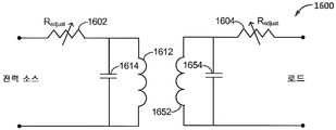
도 16 은 일 예시적인 구현에 따른, 가변 저항성 커플링을 활용한 도 15 의 커플링 회로의 부분의 개략적 다이어그램이다.
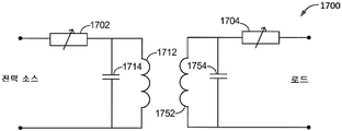
도 17 은 일 예시적인 구현에 따른, 가변 리액티브 커플링을 활용한 도 15 의 커플링 회로의 부분의 개략적 다이어그램이다.
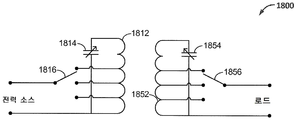
도 18 은 일 예시적인 구현에 따른, 탭핑된 인덕터 커플링을 활용한 도 15 의 커플링 회로의 부분의 개략적 다이어그램이다.
도 19 는 일 예시적인 구현에 따른, 탭핑된 커패시터 커플링을 활용한 도 15 의 커플링 회로의 부분의 개략적 다이어그램이다.
도 20 은 일 예시적인 구현에 따른, 물리적으로 조정가능한 커플링을 활용한 도 15 의 커플링 회로의 부분의 개략적 다이어그램이다.
도 21 은 일 예시적인 구현에 따른, 탭핑된 커플링 루프를 활용한 도 15 의 커플링 회로의 부분의 개략적 다이어그램이다.
도 22 는 일 예시적인 구현에 따른, 기하학적으로 눈금이 매겨진 (geometrically graduated) 루프 사이즈들을 갖는 탭핑된 커플링 루프를 활용한 도 15 의 커플링 회로의 부분의 개략적 다이어그램이다.
도 23 은 일 예시적인 구현에 따른, 1 차 공진기 위에 정렬된 차량의 다이어그램이다.
도 24 는 일 예시적인 구현에 따른, 무선 유도성 전력 전송을 위한 방법의 플로우차트를 도시한다.
도 25 는 일 예시적인 구현에 따른, 무선 유도성 전력 전송을 위한 장치의 기능적 블록 다이어그램이다.
도 26 은 일 예시적인 구현에 따른, 무선으로 전력을 유도적으로 수신하기 위한 방법의 플로우차트를 도시한다.
도 27 은 일 예시적인 구현에 따른, 무선 전력을 유도적으로 수신하기 위한 장치의 기능적 블록 다이어그램이다.
도면들에 예시된 다양한 피처들은 일정 비율로 그려지지 않을 수도 있다. 이에 따라, 다양한 피처들의 디멘젼들은 명료성을 위해 임의적으로 확대 또는 축소될 수도 있다. 추가로, 도면들 중 일부는 주어진 시스템, 방법 또는 디바이스의 컴포넌트들 모두를 도시하지 않을 수도 있다. 마지막으로, 동일한 참조 부호들은 명세서 및 도면들 전반에 걸쳐 유사한 피처들을 나타내는데 사용될 수도 있다.Figure 1 illustrates an exemplary inductor coil wire in which the skin effect may be observed.
Figure 2 illustrates one exemplary model of an electrical resonator.
3 illustrates bell as a model of an exemplary physical resonator.
4 illustrates a frequency response curve for an exemplary resonator.
5 is a functional block diagram of a wireless power transmission system, in accordance with one exemplary implementation.
Figure 6 shows a diagram of near field, transition, and far field regions for wireless resonance inductive charging, in accordance with one exemplary implementation.
Fig. 7 is a diagram of a speaker in a room with dimensions smaller than the wavelength of the sound emitted from the speaker. Fig.
8 is a diagram of a speaker in a room with dimensions greater than the wavelength of the sound emitted from the speaker.
FIG. 9 illustrates a plurality of positions of a primary resonator and a secondary resonator during wireless power throughput measurements, in accordance with one exemplary implementation.
10 illustrates power throughput versus frequency for a heavily loaded Q primary-to-secondary resonator power transfer setup, in accordance with one exemplary implementation.
11 illustrates power throughput versus frequency for a low loaded Q primary-to-secondary resonator power transfer setup, in accordance with one exemplary implementation.
12A-12F illustrate power throughput at a center frequency for several different separations between the primary resonator and the secondary resonator of FIG. 9 when loosely coupled, in accordance with one exemplary implementation.
13A-13F illustrate power throughput over a frequency bandwidth for separations between the primary resonator and the secondary resonator of FIG. 9 when coupled loosely, in accordance with one exemplary implementation.
14A-14D illustrate power throughput over a frequency bandwidth for separations between the primary resonator and the secondary resonator of FIG. 9 when tightly coupled, in accordance with one exemplary implementation.
15 is a functional block diagram of a wireless power transmission system with primary and secondary side coupling coordination capabilities, in accordance with one exemplary implementation.
16 is a schematic diagram of a portion of the coupling circuit of FIG. 15 utilizing a variable resistive coupling, in accordance with one exemplary implementation.
Figure 17 is a schematic diagram of a portion of the coupling circuit of Figure 15 utilizing variable reactive coupling, in accordance with one exemplary implementation.
Figure 18 is a schematic diagram of a portion of the coupling circuit of Figure 15 utilizing a tapped inductor coupling, in accordance with one exemplary implementation.
19 is a schematic diagram of a portion of the coupling circuit of FIG. 15 utilizing tapped capacitor coupling, in accordance with one exemplary implementation.
FIG. 20 is a schematic diagram of a portion of the coupling circuit of FIG. 15 utilizing physically adjustable coupling, in accordance with one exemplary implementation.
Figure 21 is a schematic diagram of a portion of the coupling circuit of Figure 15 utilizing a tapped coupling loop, in accordance with one exemplary implementation.
FIG. 22 is a schematic diagram of a portion of the coupling circuit of FIG. 15 utilizing a tapped coupling loop having geometricly graduated loop sizes according to one exemplary implementation.
23 is a diagram of a vehicle arranged on a primary resonator, according to one exemplary implementation.
24 illustrates a flow chart of a method for wireless inductive power transmission, according to one exemplary implementation.
25 is a functional block diagram of an apparatus for wireless inductive power transmission, according to one exemplary implementation.
26 illustrates a flowchart of a method for inductively receiving power wirelessly, in accordance with one exemplary implementation.
27 is a functional block diagram of an apparatus for inductively receiving wireless power, according to one exemplary implementation.
The various features illustrated in the figures may not be drawn at a constant rate. Accordingly, the dimensions of the various features may be arbitrarily enlarged or reduced for clarity. In addition, some of the drawings may not show all of the components of a given system, method, or device. Finally, like reference numbers may be used to denote like features throughout the specification and drawings.
첨부된 도면들과 관련하여 이하 기재된 상세한 설명은 본 발명의 소정의 구현들의 설명으로서 의도되고 본 발명이 실시될 수도 있는 유일한 구현들을 나타내도록 의도되지 않는다. 본 설명 전반에 걸쳐 사용된 용어 "예시적인" 은 "일 예, 인스턴스, 또는 예시로서 기능하는 것" 을 의미하고, 선호되거나 또는 다른 예시적인 구현들에 비해 유리한 것으로 반드시 해석되는 것은 아니어야 한다. 상세한 설명은 개시된 구현들의 철저한 이해를 제공하는 목적을 위해 특정 상세들을 포함한다. 일부 인스턴스들에서, 일부 디바이스들은 블록 다이어그램 형태로 도시된다.The following detailed description with reference to the accompanying drawings is intended as a description of certain implementations of the invention and is not intended to represent the only implementations in which the invention may be practiced. The word "exemplary " used throughout this description shall mean" serving as an example, instance, or illustration, "and should not necessarily be construed as advantageous over other or exemplary implementations. The detailed description includes specific details for the purpose of providing a thorough understanding of the disclosed implementations. In some instances, some devices are shown in block diagram form.
무선 전력 전송은 전기장, 자기장, 전자기장, 또는 다른 것과 연관된 임의의 형태의 에너지를, 물리적 전기 도체들의 이용 없이 (예를 들어, 전력은 자유 공간을 통해 전송될 수도 있다) 송신기로부터 수신기로 전송하는 것을 지칭할 수도 있다. "송신 안테나" 또는 "1 차 공진기" 에 의해 무선장 (예를 들어, 자기장 또는 전자기장) 으로 출력된 전력은 "수신 안테나" 또는 "2 차 공진기" 에 의해 수신되거나, 캡처되거나, 또는 커플링되어 전력 전송을 달성할 수도 있다.Wireless power transmission may involve transferring any form of energy associated with an electric field, magnetic field, electromagnetic field, or the like from a transmitter to a receiver without the use of physical electrical conductors (e.g., power may be transmitted through free space) It can also be called. The power output by a "transmit antenna" or "primary resonator" to a radio field (eg, magnetic field or electromagnetic field) is received, captured, or coupled by a "receive antenna" or a " Power transmission may be achieved.
고도 공진, 또는 고 "품질 팩터" (즉, Q) 를 이용하면, 공진기들은 1 차 코일에 주입된 에너지로 하여금, 비-공진 1 차 코일로 가능한 것을 훨씬 넘어서 자기장을 재순환 및 구축하는 것을 가능하게 한다. 유사하게, 고 Q 2 차 공진기는 저 Q 2 차 공진기보다 자기장을 더 많이 캡처하고 그것을 유용한 전력으로 바꿀 수도 있다. 그러나, 시스템의 고 동작 Q 를 유지 및 안정화하면서 1 차 공진기 안으로 에너지를 효율적으로 커플링하고, 1 차 공진기와 2 차 공진기 사이에 효율적으로 에너지를 커플링하고, 그리고 2 차 공진기 밖으로 효율적으로 에너지를 커플링하는데 있어서 어려움을 경험하였다.Using a high resonance, or a high "quality factor" (i.e., Q), the resonators enable the energy injected into the primary to recirculate and build up the magnetic field well beyond what is possible with a non- resonant primary do. Similarly, a high Q secondary resonator may capture more magnetic field than a low Q secondary resonator and turn it into useful power. However, by efficiently coupling energy into the primary resonator while maintaining and stabilizing the high Q of the system, coupling energy efficiently between the primary resonator and the secondary resonator, and efficiently delivering energy out of the secondary resonator And experienced difficulties in coupling.
본 출원은 시스템의 엘리먼트들 사이 (예를 들어, 전력 소스와 1 차 공진기 사이, 1 차 공진기와 2 차 공진기 사이, 그리고 2 차 공진기와 로드 사이) 의 커플링의 코디네이션된 조정이, 양자가 시스템의 최적의 동작 포인트를 변화시킬 수도 있는, 전력이 전송될 거리의 변동에 응답하여 뿐만 아니라 로드의 변동에 응답하여 달성될 수도 있는 방법을 기술한다. 예를 들어, 거리 및 Q 가 증가됨에 따라, 최적의 동작 포인트는 코디네이션된 방식으로 1 차 공진기와 2 차 공진기 양자에서의 커플링의 조정 없이 안정화하기에 점점 더 결정적이고 어려워진다. 처음으로, Q 의 논의가 뒤따른다.The present application discloses that a coordinated adjustment of the coupling between elements of the system (e.g., between the power source and the primary resonator, between the primary resonator and the secondary resonator, and between the secondary resonator and the load) Lt; / RTI > may be achieved in response to variations in the load as well as variations in the distance over which power is to be transmitted, which may change the optimal operating point of the power supply. For example, as the distance and Q increase, the optimum operating point becomes increasingly more critical and difficult to stabilize without coordination of coupling in both the primary resonator and the secondary resonator in a coordinated manner. For the first time, discussion of Q follows.
Q 는 컴포넌트의 품질, 공진기의 에너지 저장 능력 (예를 들어, 전기적, 기계적 또는 물리적) 및 회로의 주파수 선택성을 포함하지만 이들에 제한되지는 않는 많은 엔지니어링 목적들을 위해 이용된 무단위 (unit-less) 양이다. Q 는 특정한 회로의 바람직한 품질들 대 바람직하지 않은 품질들의 비이다. 보다 구체적으로는, Q 는 특정한 공진 시스템에서의 저장된 에너지 (예를 들어, 양호한 스터프 (good stuff)) 대 소산된 에너지 (예를 들어, 열악한 스터프 (bad stuff)) 의 비이다. Q 는 인덕터들 또는 커패시터들의 리액턴스 (예를 들어, 양호한 스터프) 대 유효 저항 (예를 들어, 열악한 스터프) 의 비로서 또한 정의될 수도 있다.Q is a unit-less, non-limiting example used for many engineering purposes, including, but not limited to, the quality of components, the energy storage capability of resonators (e.g., electrical, mechanical or physical) It is a quantity. Q is the ratio of the desired to the undesirable quality of a particular circuit. More specifically, Q is the ratio of stored energy (e.g., good stuff) to dissipated energy (e.g., bad stuff) in a particular resonant system. Q may also be defined as the ratio of the reactance (e.g., good stuff) of the inductors or capacitors to the effective resistance (e.g., poor stuff).
물리적 공진기들의 예들은 휘슬 (whistle) 들, 스트링 악기 (string instrument) 들, 스윙 진자 (swinging pendulum) 들, 및 링잉 벨 (ringing bell) 들을 포함할 수도 있다. 예를 들어, 휘슬에서, 공기가 개구부를 지나서 흐르고 공기압 또는 공기 흐름이 발진하기 시작할 때 사운드가 생성된다. 톤 (tone) 의 주파수는 휘슬의 사이즈 및 형상에 의해 결정된다. 트럼펫은 밸브들이 공기 경로를 변화시켜 상이한 주파수들에서 음 (note) 들을 생성하는 물리적 공진기의 다른 예이다. 마찬가지로, 스트링 악기들은 기계적 진동들을 이용하여 사운드를 생성한다. 뜯을 때 더 높은 음들을 생성하는 더 짧은 스트링들과 비교하여 더 긴 스트링들은 뜯을 때 낮은 음들을 생성한다. 진자들은 물리적 공진기들의 또 다른 예를 제공한다. 진자는 앞뒤로 자유롭게 스윙하는 긴 막대에 달려 있는 추로 구성된다. 스트링과 유사하게, 더 긴 막대는 진자에, 발진의, 더 긴 주기, 또는 더 낮은 주파수를 부여한다. 진자 추가 한쪽으로 변위될 때, 그것은 상승되고, 이는 그 추에 위치 에너지를 부여한다. 추가 중심을 향하여 다시 스윙할 때, 위치 에너지는 운동 에너지로 변환된다. 진자 추가 중심을 거쳐 다른 쪽으로 스윙할 때, 운동 에너지는 다시 위치 에너지로 변환된다. 따라서, 진자가 스윙함에 따라, 진자는 에너지를 위치 에너지와 운동 에너지 사이에서 왔다갔다 계속해서 변환한다. 보다 친숙한 물리적 공진기들로부터, 우리의 논의가 전기적 공진기들로 바뀔 수도 있다. 전기 회로들에서, 인덕터들 및 커패시터들이 상기 언급된 물리적 공진기들에서와 같이 공기 기둥들, 스트링들 또는 진자들 대신에 발진들을 제어하기 위해 이용된다. 전자기 유도의 이론에 따르면, 와이어에서의 전류는 와이어 주위에 자기장을 유도하고 와이어를 가로 질러가는 자기장이 와이어에서 전류를 유도한다. 인덕터들은 자기장에서의 에너지를 저장하는 와이어의 코일들이다. 인덕터는 그것을 통해 흐르는 전류의 변화들을 방해한다. 이런 이유로, 인덕터를 통과한 전류 파형은 전압 파형보다 90°(예를 들어, 1/4 사이클) 만큼 뒤떨어진다. 와이어의 더 많은 턴들 또는 더 큰 턴들을 갖는 인덕터들은 더 많은 인덕턴스를 갖는다. 실제로, 와이어는 종종 철을 포함한 코어 재료 주위에 감기고, 이는 플럭스의 자력선들을 집중시키고 턴들의 수 및 주어진 단면에 대한 인덕턴스를 증가시킨다. 완전한 인덕터는 손실 없이 자기장의 에너지를 저장할 것이다. 그러나, 실세계의 인덕터들의 와이어는 저항을 갖는다. 추가로, 인덕터가 철을 포함한 코어 재료를 포함한다면, 그 코어 내에 히스테리시스 및 와전류들과 연관된 추가적인 손실들이 존재한다. 통상적으로, 전력 회로에서 이용된 인덕터는 동작 주파수에서의 저항으로 인한 손실보다 적어도 100 배 더 큰 유도 리액턴스를 보인다. 다시 말해서, 언로딩된 또는 고유 Q 는 실제 시스템들의 경우 100 보다 더 크다. 인덕터들에서의 손실의 이슈는 무선 전력의 논의에 있어서 중요해진다.Examples of physical resonators may include whistles, string instruments, swinging pendulums, and ringing bells. For example, in a whistle, a sound is produced when air flows past an opening and air pressure or air flow begins to oscillate. The frequency of the tone is determined by the size and shape of the whistle. A trumpet is another example of a physical resonator in which valves vary air paths to produce notes at different frequencies. Likewise, string instruments produce sound using mechanical vibrations. Compared to shorter strings that produce higher tones when tapped, longer strings produce lower tones when tapped. Pendulums provide another example of physical resonators. The pendulum consists of a weight on a long bar that swings freely back and forth. Similar to a string, a longer rod gives the pendulum a longer period of oscillation, or a lower frequency. When displaced to the side of the pendulum addition, it is lifted, which imparts potential energy to the weight. When swinging again toward the additional center, the kinetic energy is converted into kinetic energy. When swinging to the other side through the center of pendulum addition, kinetic energy is again converted into position energy. Thus, as the pendulum swings, the pendulum continually converts energy back and forth between the kinetic energy and the kinetic energy. From more familiar physical resonators, our discussion may turn into electrical resonators. In electrical circuits, inductors and capacitors are used to control oscillations instead of air columns, strings or pendulums as in the above-mentioned physical resonators. According to the theory of electromagnetic induction, current in a wire induces a magnetic field around the wire and a magnetic field that traverses the wire induces current in the wire. Inductors are coils of wire that store energy in the magnetic field. The inductor interferes with changes in current flowing through it. For this reason, the current waveform passing through the inductor lags behind the voltage waveform by 90 degrees (for example, 1/4 cycle). Inductors with more turns of wire or larger turns have more inductance. In practice, the wire is often wound around the core material, including the iron, which concentrates the flux lines of the flux and increases the number of turns and the inductance for a given cross section. A complete inductor will store the energy of the magnetic field without loss. However, the wires of real-world inductors have resistances. Additionally, if the inductor comprises a core material comprising iron, there are additional losses associated with hysteresis and eddy currents in the core. Typically, inductors used in power circuits exhibit inductive reactances at least 100 times greater than losses due to resistance at the operating frequency. In other words, unloaded or native Q is greater than 100 for real systems. The issue of losses in inductors becomes important in the discussion of wireless power.
커패시터들은 절연체에 의해 분리된 평행 전도성 플레이트들을 포함한다. 커패시터들은 그 플레이트들 사이에 전기장의 에너지를 저장한다. 인덕터가 그것을 통해 흐르는 전류의 변화들을 방해하는 경우, 커패시터는 그 플레이트들에 걸쳐 부여된 전압의 변화들을 방해한다. 이런 이유로, 커패시터를 통과한 전류 파형은 전압 파형을 90°(예를 들어, 1/4 사이클) 만큼 앞선다. 더 큰 플레이트들 및 그 플레이트들 사이의 더 가까운 간격은 커패시턴스를 증가시킨다. 추가로, 플레이트들 사이의 절연체, 또는 유전체는 그 플레이트들이 주어진 플레이트 단면 및 분리를 위해 더 많은 전기 전하를 저장하는 것을 허용함으로써 커패시턴스를 증가시킬 수도 있다. 커패시터들은 플레이트들의 저항 뿐만 아니라 유전 재료로 인한 손실들을 갖고, 이는 전기장의 부분을 소산한다. 실제 무선 전력 회로들에서, 인덕터들의 손실들은 보통 커패시터들의 손실들을 좌우한다. 따라서, 인덕터들이 일반적으로 회로의 성능을 정의한다. 인덕터에서의 와이어의 직류 (DC) 저항 (rdc) 이 손실을 나타낸 경우, 과중한, 순구리 와이어를 이용하면 손실을 최소화할 수 있다. 그러나, 더 높은 주파수들에서, 거리에 걸친 유도 커플링이 실용적인 경우, "스킨 효과 (skin effect)" 라 불리는 현상이 중요해진다. 와이어에서의 고주파수 손실의 상세들은 "The Influence of Frequency upon the Self-Inductance of Coils" (August 1906), Bulletin of the Bureau of Standards, vol. 2, 275-296, 1906, Scientific Paper 37 에서 확인될 수 있다.The capacitors include parallel conductive plates separated by an insulator. The capacitors store the energy of the electric field between the plates. If the inductor interferes with changes in the current flowing through it, the capacitor interferes with changes in voltage applied across the plates. For this reason, the current waveform passed through the capacitor goes 90 degrees (e. G., 1/4 cycle) in voltage waveform. The larger plates and the closer spacing between the plates increases the capacitance. In addition, an insulator, or dielectric, between the plates may increase the capacitance by allowing the plates to store more electrical charge for a given plate cross section and separation. The capacitors have losses due to the dielectric material as well as the resistance of the plates, which dissipate a portion of the electric field. In actual wireless power circuits, the losses of the inductors usually dominate the losses of the capacitors. Thus, inductors generally define the performance of the circuit. If the direct current (dc) resistance (r dc ) of the wire in the inductor exhibits loss, then excessive, pure copper wire can be used to minimize losses. However, at higher frequencies, when inductive coupling across a distance is practical, a phenomenon called "skin effect" becomes important. Details of the high frequency losses in the wire are described in "The Influence of Frequency on the Self-Inductance of Coils" (August 1906), Bulletin of the Bureau of Standards, vol. 2, 275-296, 1906, Scientific Paper 37, which is incorporated herein by reference.
도 1 은 스킨 효과가 관찰될 수도 있는 일 예시적인 인덕터 코일 와이어 (100) 를 예시한다. 와이어 (100) 에서의 교류는 "오른손 법칙" 에 따라 교류에 직각으로 와이어 내에 및 주위에 교류 자기장 (106) 을 생성한다. 자기장 (106) 은 차례로 "오른손 법칙" 에 따라, 다시 자기장에 직각으로 와이어에서 와전류들 (108) 을 유도한다. 이들 와전류들 (108) 은 와이어의 중간의 전류 (Icenter) 의 흐름을 방해하여, 전류가 강제로 와이어의 표면 (Iskin) 근처에 흐르게 한다. 이 스킨 효과는 고주파 전류가 강제로 와이어의 외부 표면 근처에만 흐르게 하고, 이는 와이어 (100) 의 유효 단면 (예를 들어, 회색 음영된 영역) 을 감소시키고 따라서 저항을 증가시킨다. 전류 밀도가 최대치 (예를 들어, 컨덕터의 표면에서의 값) 의 대략 37% 로 떨어진 컨덕터의 표면 아래의 깊이는 "스킨 깊이" (104) 로 알려져 있다. 이 스킨 효과로 인해, 98% 초과의 전류가 컨덕터의 표면으로부터 스킨 깊이의 4 배의 깊이 내에서 흐를 것이다. 스킨 효과는 주파수의 증가로 증가한다. 예를 들어, 100kHz (예를 들어, 고전력 전기 차량 충전을 위해 통상 이용되는 주파수) 에서, 구리 와이어에 대한 스킨 깊이는 대략 0.2mm 이다. 따라서, 거의 모든 전류는 100kHz 에서 큰 게이지 와이어의 외부 0.8mm 에서 흐를 것이다. 이것은 와이어의 저항을 크게 증가시킨다. 이런 이유로, rdc 는 공진 계산들에 있어서 유용하지 않다. 이에 따라, 실제로, 고전력 무선 전력 전송 애플리케이션들은 많은 더 작은 게이지 절연된 와이어들이 병렬로 감겨있고 번들의 내측으로부터 외측으로 엮여서 각각의 와이어가 매 다른 와이어와 내측에 길이의 동일한 프랙션을 가져, 스킨 깊이 손실들을 최소화하는 리츠 와이어를 활용한다. 도 2 는 전기적 공진기 (200) 의 일 예시적인 모델을 예시한다. L-C 공진기들에 대한 광범위한 배경 및 설계 정보는 Radio Instruments and Measurements, U.S. Department of Commerce, National Bureau of Standards, Circular C74 에서 확인될 수 있다.Figure 1 illustrates an exemplary
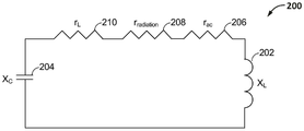
전기적 공진기 (200) 는 인덕터 (202) 가 커패시터 (204) 에 연결될 때 형성된다. L-C 공진기 (200) 는 그것이 에너지를 저장하기 때문에 종종 "탱크 회로" 라 불린다. 일단 에너지가 L-C 공진기 (200) 로 도입되면, 인덕터 (202) 의 자기장에서 에너지가 점점 커지는 한편 커패시터 (204) 의 전기장은 대폭 감소되고, 그 후 사이클은 뒤바뀌고 자기장은 붕괴하여, 에너지가 커패시터 (204) 의 전기장에서 점점 커지게 된다. 공진에서, 인덕터 (202) 의 유도 리액턴스 (XL) 및 커패시터 (204) 의 용량 리액턴스 (XC) 는 크기에 있어서 동일하고 위상 변위에 있어서 반대이다. 이것은 공진기에서의 전압 및 전류가 서로 동위상이 되게 하는 공진에서의 L-C 공진기의 특별한 동작 피처이다. 이 공진 액션은 이전에 설명한 바와 같은 진자와 유사하다. 그러나, 진자의 위치 및 운동 에너지의 교번 대신에, 전기적 공진기는 인덕터의 자기장과 커패시터의 전기장에서의 에너지 저장을 교번시킨다. 진자의 경우와 같이, L-C 공진기에서의 에너지의 앞뒤로의 흐름은 초기 에너지가 공진기 내로 주입된 후 오랫동안 지속할 수 있다. 진자 예에서, 추를 결국 늦추는 손실은 공기 저항이다. 실제의 L-C 공진기에서, 가장 큰 손실은 인덕터 와이어의 AC 저항 (rac) 에 있으며, 이는 도 2 에서 저항 (206) 에 의해 모델링될 수도 있다. L-C 공진기 (200) 의 모델은 또한, 원거리장 전자기 (EM) 파 전파로 인한 방사 손실들을 설명하기 위한 저항 (208) (rradiation) 뿐만 아니라 로드를 설명하기 위한 저항 (210) (rL) 을 포함할 수도 있다. 그러나, 이하 더 상세히 설명될 바와 같이, rradiation 은 공진 유도성 전력 전송 애플리케이션들의 경우 rac 와 비교하여 극도로 작고, 그래서 본 논의의 경우, 그것은 무시될 수도 있다. 논의가 현재 컴포넌트 Q 에 초점을 맞추고 있기 때문에, 로드 저항 (210) (rL) 또한 본 논의에 있어 무시될 수도 있다.The
컴포넌트들의 품질이 공진 회로 (200) 의 동작에 매우 중요하기 때문에, 측정치 Q 가 이용된다. 컴포넌트 Q 는 인덕터 (202) 의 리액턴스 (XL) 또는 커패시터 (204) 의 리액턴스 (XC), 대 rac (여기서 rac 는 Q 가 측정 또는 계산되고 있는 컴포넌트의 AC 저항이다) 의 비로서 정의된다. 이전에 기재한 바와 같이, 유도 또는 용량 리액턴스는 그것이 공진기 (200) 에 저장된 에너지에 기여하기 때문에 "양호한 스터프" 인 한편, rac 는 그것이 공진기 컴포넌트들에서 열로서 손실된 에너지에 기여하기 때문에 "열악한 스터프" 이다. 컴포넌트 Q 는 이하의 식 1 및 식 2 에 따라 계산될 수도 있다.Since the quality of the components is very important for the operation of the
식 1 : QL = XL/rac 인덕터의 컴포넌트 QL Equation 1: Q L = X L / r ac The component of the inductor Q L
식 2 : QC = XC/rac 커패시터의 컴포넌트 QC Equation 2: Q C = X C / r ac Component Q C of the capacitor
무선 전력 전송에 이용되는 인덕터들에 대한 통상의 컴포넌트 Q 값들은 최고 품질 인덕터들의 경우 대략 100 과 500 사이일 수도 있는 한편, 커패시터들은 통상적으로 수 천 내지 수 만의 컴포넌트 Q 값들을 갖는다.Typical component Q values for inductors used for wireless power transmission may be between approximately 100 and 500 for best quality inductors, while capacitors typically have component Q values of several thousands to tens of thousands.
인덕터의 리액턴스는 이하의 식 3 에 따라 계산될 수도 있고, 여기서 f 는 헤르츠 (Hz) 단위의 동작 주파수이고, L 은 헨리 (H) 단위의 인덕터의 인덕턴스이고, 그리고 그리스 문자 오메가 (ω) 는 초당 라디안 단위의 각주파수 (예를 들어, 2πf) 이다.Where f is the operating frequency in hertz and L is the inductance of the inductor in Henry H and the Greek letter Omega is in degrees per second (For example, 2? F) in radians.
식 3 : XL = 2πfL = ωL 인덕터의 리액턴스 Equation 3: X L = 2πfL = ωL Reactance of the inductor
식 1 을 재배열함으로써, 전기 차량 충전 패드에서의 코일의 AC 저항 (rac) 은 식 4 에 따라 측정된 또는 계산된 코일 인덕턴스 (XL) 를 활용하여 계산될 수도 있다.By rearranging
식 4 : rac = XL/QL 인덕터의 AC 저항 Equation 4: r ac = X L / Q L AC resistance of the inductor
이에 따라, 7 개의 턴들, 58μH 의 인덕턴스, 어떤 차량도 존재하지 않을 때의 500 의 Q, 및 차량이 존재하지만 충전하지 않을 때의 300 의 Q 를 갖는 1 미터 직경 코일이 80kHz 의 주파수에서 드라이빙되는 일 예에서, 어떤 차량도 존재하지 않는 동안의 인덕터의 AC 저항은 rac = 2π*80,000*0.000058/500 = 58mΩ 일 것이다.Thus, a 1 meter diameter coil with 7 turns, 58 μH inductance, 500 Q when no vehicle is present, and 300 Q when the vehicle is present but not charging, is driven at a frequency of 80 kHz In the example, the AC resistance of the inductor while no vehicle is present would be r ac = 2π * 80,000 * 0.000058 / 500 = 58mΩ.
공진기 (예를 들어, 공진기 (200)) 의 에너지 저장 능력이 또한 Q 로 알려져 있다. 이 Q 는 공진기 단독의 고유 또는 언로딩된 Q 이다. 그에 반해서, 공진기는 또한 로딩된 Q 를 갖고, 이는 그것이 로딩될 때 공진기의 에너지 저장 능력이다.The energy storage capability of a resonator (e.g., resonator 200) is also known as Q. This Q is the unique or unloaded Q of the resonator alone. On the other hand, the resonator also has a loaded Q, which is the energy storage capability of the resonator when it is loaded.
유용하게는, 일부 에너지가 공진기로부터 추출되어야 한다. 진자에 의해 드라이빙된 클록의 경우에, 에너지는 표면상으로는 시계를 돌리는 기어들을 드라이빙하기 위해 진자로부터 추출된다. 무선 전력 전송의 경우에, 전력은 배터리를 충전하거나 디바이스 또는 차량을 동작시키기 위해 추출된다. 에너지가 공진기로부터 추출되어야 하면, 에너지는 먼저 공진기 안으로 주입되어야 한다. 진자-드라이빙된 클록의 경우, 별개의 낙추 시스템이 그것을 스윙 상태로 유지하기 위해 진자에 "푸시" 를 부여함으로써 진자 안으로 에너지를 주입하는데 이용된다. 이 방식으로, 낙추 시스템에 저장된 위치 에너지는 진자에서 운동 에너지로 트랜스퍼된다. 무선 전력 시스템의 경우, 소스 (예를 들어, 그리드 전력공급되거나 다른 전력 소스, 이를 테면 배터리를 통함) 는 공진기 안으로 에너지를 커플링한다. 에너지의 공진기 안으로의 주입 및 공진기 밖으로의 추출 양자는 각각 마치 공진기가 추가적인 손실들을 갖는 것처럼 공진기의 발진을 로딩한다. 이것은 Q 를 효과적으로 낮춘다. 이것은 로딩된 또는 동작 Q 로 알려져 있다.Advantageously, some energy must be extracted from the resonator. In the case of a clock driven by a pendulum, the energy is extracted from the pendulum to drive gears that rotate clockwise on the surface. In the case of wireless power transmission, the power is extracted to charge the battery or to operate the device or vehicle. If energy is to be extracted from the resonator, the energy must first be injected into the resonator. For pendulum-driven clocks, a separate retracting system is used to inject energy into the pendulum by imparting a "push" to the pendulum to keep it in the swing state. In this way, the position energy stored in the declining system is transferred from the pendulum to kinetic energy. In the case of a wireless power system, a source (e.g., grid powered or another power source, such as a battery) couples energy into the resonator. Both the injection of energy into the resonator and the extraction out of the resonator both load the oscillation of the resonator as if the resonator had additional losses. This effectively lowers Q. This is known as loaded or motion Q.
언로딩된 Q 대 로딩된 Q 의 개념을 구상하는 것을 돕기 위해, 링잉 벨에 대한 유추가 유용할 수도 있다. 도 3 은 일 예시적인 물리적 공진기의 모델로서 벨 (300) 을 예시한다. 벨 (300) 은 기계적 진동들의 에너지를 저장하는 물리적 공진기이다. 진동들은 벨 (300) 의 마우스를 플렉싱하게 한다. 클래퍼 (302) 에 의한 벨 (300) 의 초기 스트라이킹은 벨 (300) 로 에너지를 부여하여 벨 (300) 을 구부러지게 하여, 그 정지하고 있는 라운드 형상 (304) 과 타원 형상 (306) 간에 발진하게 한다. 이것은 발진 스프링에 저장한 것과 유사한, 저장된 위치 에너지의 형태이다. 이 위치 에너지는 벨의 마우스의 형상이 앞뒤로 발진할 때 사운드 파들의 형태로 시간의 경과에 따라 릴리스된다. 클래퍼 (302) 의 날카로운 스트라이크는 추가 로딩 없이 에너지를 벨 (300) 에 부여하여, 고 Q 기계적 공진기가 드라이빙력에 의해 방해받지 않고 발진하게 한다. 이것은 무선 전력 전송 시스템의 1 차 공진기와 에너지 소스 사이의 매우 루스한 커플링과 유사하며, 이는 1 차 공진기가 드라이빙력에 의해 실질적으로 언로딩되어 발진하게 한다. 벨 (300) 둘레의 공기는 진동의 모션을 저항함으로써 벨 (300) 을 로딩한다. 공기는 에너지를 추출하기 위해 2 차 공진기에 커플링되는 로드와 유사하다. 스트라이킹된 후에 벨 (300) 이 링잉하는 시간은, 에너지 대부분이 사운드 파들의 형태로 릴리스될 때, 그 로딩된 Q 의 측정치이다. 그에 반해서, 벨 (300) 이 진공에 배치되었고 벨 (300) 이 링잉을 멈추는데 걸리는 시간이 측정되었다면, 이 측정은 단지 에너지 손실이 공진기에 고유할 것이고 이는 벨 (300) 의 만곡부-유도 가열로부터 발생하기 때문에 벨 (300) 의 언로딩된 Q 를 드러낼 것이다.To help visualize the concept of unloaded Q vs. loaded Q, analogy to ringing bell may be useful. FIG. 3 illustrates
공진기의 로딩된 Q 를 계산하는 것은 언로딩된 Q 와 동일한 로직을 뒤따른다. 다시, 그것은 저장된 에너지 대 소산된 에너지의 비이다. 공진기 상의 로드가 소산 팩터이기 때문에, 그것은 도 2 에 도시한 바와 같이 공진기 (200) 의 다른 컴포넌트들과 직렬의 저항 (210) (rL) 으로서 표현될 수도 있다. 따라서, 로딩 저항 (rL) (극도로 작은 방사 손실들 (rradiation) 을 방치) 에 컴포넌트 손실 저항 (rac) 을 추가함으로써, 로딩된 Q (QLOADED) 는 이하의 식 5 에 도시한 바와 같이 리액턴스 대 저항들의 비에 따라 결정될 수도 있다.Calculating the loaded Q of the resonator follows the same logic as unloaded Q. Again, it is the ratio of stored energy to dissipated energy. Because the load on the resonator is a dissipation factor, it may be represented as a resistor 210 (r L ) in series with the other components of the
식 5 : QLOADED = XL/(rac + rL) 진공기의 로딩된 Q Equation 5: Q LOADED = X L / (r ac + r L ) The loaded Q
실제로, 저항기 자체의 손실들은 설계에 의해 최소화되기 때문에 그리고 로딩은 반드시 회로 안으로 또는 회로 밖으로 유용한 전력을 전송하기에 크기 때문에 rL>>rac 이다. 따라서, 식 5 는 이하의 식 6 의 근사화로 단순화될 수도 있다.In practice, the losses in the resistors themselves are minimized by design, and loading is always r L >> r ac because it is large enough to transfer useful power into or out of the circuit. Therefore,
식 6 : QLOADED = XL/rL 진공기의 근사 로딩된 Q Equation 6: Q LOADED = X L / r L binary approximation the loaded Q of the air
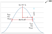
Q 에 대한 상기 논의는 이제까지는 공진기에서 에너지를 소산하는데 걸리는 시간에 기초하였다. 그러나, 공진기들은 또한, 공진기가 발진할 수 있는 주파수들의 범위 또는 대역폭의 속성을 갖는다. 대역폭은 에너지 소산의 레이트에 밀접하게 관련된다. 에너지를 빨리 소산하는 공진기들은 넓은 대역폭들을 갖는 한편, 더 긴 발진들을 지속시키는 공진기들은 좁은 대역폭들을 갖는다. 편의를 위해, 대역폭은 일반적으로는, 발진들이 피크 응답 값의 1/2 보다 더 큰 값에서 발생하는 주파수 범위로서 정의된다. 시각화의 용이함을 위해, 도 4 는 일 예시적인 공진기에 대한 주파수 응답 곡선 (400) 을 예시한다. 피크 응답은 "중심 주파수", 예를 들어, ωC 또는 fC 로서 지정된다. 예를 들어, 공진기의 대역폭을 결정하면 피크 공진 값을 발견한다. 최대 임계적으로 커플링되거나 임계 미만으로 커플링된 환경들 하에서, 단일 피크 응답은 중심 주파수에서 발생한다. 이제 응답이 피크 값의 1/2 일 때까지 주파수는 감소한다. 이 값은 하위 컷오프 주파수 (flower 또는 ωlower) 이다. 그 후, 중심 주파수에서 다시 시작하여, 응답이 다시 피크의 1/2 일 때까지 주파수는 증가한다. 이 값은 상위 컷오프 주파수 (fupper 또는 ωupper) 이다. 상위 컷오프 주파수와 하위 컷오프 주파수 간의 차이는 이하의 식 7 및 식 8 에 의해 나타낸 바와 같이, 대역폭이고, 여기서 문자 델타 (![]()
![]()
식 7 : 대역폭 = fupper - flower = ![]()
![]()
식 8 : 대역폭 = ωupper - ωlower = ![]()
![]()
주파수의 유닛들은 중심 주파수 fc 또는 ωc 의 프랙션으로서 대역폭을 표현함으로써 식으로부터 제거될 수 있다. 그것이 나타남에 따라, 공진기의 대역폭은 그 Q 에 반비례하고, 이는 이하의 식 9 및 식 10 에 나타낸 Q 에 대한 대안적 표현들이 생기게 하며, 여기서 ωc 는 중심 각주파수이고 fc 는 중심 주파수이다.The units of frequency can be removed from the equation by expressing the bandwidth as a fraction of the center frequency f c or ω c . It according to appear, the bandwidth of the resonator and causing are inversely proportional, and this alternative expression for Q shown in equation 9 and
식 9 : ![]()
![]()
![]()
![]()
식 10 : Q = ωc/![]()
![]()
![]()
![]()
다음은 2 개의 예시적인 공진기들에 대한 예의 대역폭 계산들이다. 제 1 예에서, 중심 주파수 fc = 100Hz 및 Q = 25 를 가진 공진기를 가정하면, ![]()
![]()
![]()
![]()
추가로, 그리스 문자 감마 (Γ) 는 공진 폭 (예를 들어, 대역폭의 절반), 또는 중심 주파수 (fc) 로부터 컷오프 주파수들 (예를 들어, fupper 또는 flower) 의 편차를 위해 일반적으로 이용된다. 따라서, 공진 폭 (Γ) 은 이하의 식 11 에 따라 표현될 수도 있다.Additionally, the Greek letter gamma (Γ) is a common for the deviation of the resonance width (for example half of the bandwidth), or the center frequency of the cutoff frequency (e.g., f upper or f lower) from (f c) . Therefore, the resonance width (G) may be expressed by the following Expression (11).
식 11 : Γ = ![]()
![]()
![]()
![]()
![]()
![]()
![]()
![]()
식 12 : Γ = ωc/2Q = fc/2Q Equation 12: Γ = ω c / 2Q = f c / 2Q
식 13 : Q = ωc/2Γ = fc/2Γ Equation 13: Q = ω c / 2Γ = f c / 2Γ
상기와 같이, Γ 는 프랙셔널 대역폭으로서 표현될 수도 있고, 여기서 주파수는 이하의 식 14 에 의해 나타낸 바와 같이, 식으로부터 사라진다.As described above, Γ may be expressed as a fractional bandwidth, where the frequency disappears from the equation, as shown by Equation 14 below.
식 14 : Q = 1/2Γ Equation 14: Q = 1 / 2Γ
거리에 걸쳐 전력을 무선으로 전송하기 위해 2 개의 공진기들이 필요하다; 하나는 전기 전력 소스를 자기장으로 변환하기 위한 1 차 공진기의 역할을 하고, 다른 것은 자기장으로부터 전력을 흡수하고 그것을 전기 전력으로 변환하기 위한 2 차 공진기의 역할을 한다. 이 논의는 1 차 공진기가 소스이고 2 차 공진기가 전력 전송의 싱크인 변압기 액션과 관련된다. 변압기 액션에 대한 엔지니어링 공식들이 무선 전력 전송의 동작을 정확하게 설명하기 때문에 이를 구분하는 것이 중요한다. 그에 반해서, 라디오파 전파에 대한 공식들은 무선 전력 전송의 맥락에서 부정확할 뿐만 아니라, 그들은 당면한 구성들에 대해 정의되지 않는다. 간단한 설명이 도 5 에 대하여 뒤따른다.Two resonators are required to transmit power wirelessly over a distance; One serving as a primary resonator for converting an electric power source into a magnetic field and the other serving as a secondary resonator for absorbing power from a magnetic field and converting it to electrical power. This discussion relates to the transformer action where the primary resonator is the source and the secondary resonator is the sink of the power transmission. It is important to distinguish the engineering formulas for transformer actions because they accurately describe the operation of the wireless power transmission. On the contrary, the formulas for radio wave propagation are not only inaccurate in the context of wireless power transmission, but they are not defined for the immediate configurations. A brief description follows with respect to Fig.
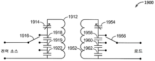
도 5 는 일 예시적인 구현에 따른, 무선 전력 전송 시스템 (500) 의 기능적 블록 다이어그램이다. 시스템 (500) 은 소스 (502), 예를 들어, AC 플러그로부터 전력을 수신한다. 주파수 생성기 (504) 는 에너지를 송신기 (510) 에 커플링하기 위해 이용된다. 송신기 (510) 는 커플링 회로 (511) (예를 들어, 하나의 예로서 유도 또는 커플링 루프, 이는 1 차 공진기 (512) 에 유도적으로 커플링되지만, 1 차 공진기 (512) 로부터 전기적으로 또는 전기화학적으로 격리된다) 를 포함한다. 1 차 공진기 (512) 는 다수 (N 개) 의 코일 루프들 (예를 들어, 인덕터) (513) 을 포함한다; 각각의 루프는 반지름 (rA) 을 갖는다. 여기에 가변 커패시터로 도시된 커패시터 (514) 는 코일 루프들 (513) 과 직렬로 위치될 수도 있어, 도 2 와 관련하여 이전에 설명한 바와 같이, 공진 루프를 형성한다. 구현에서, 커패시터는 코일 루프들 (513) 로부터 완전히 분리된 구조이다. 그러나, 소정의 구현들에서, 코일 루프들 (513) 을 형성하는 와이어의 자기-용량은 커패시터 (514) 를 형성할 수도 있다. 주파수 생성기 (504) 는 1 차 공진기 (512) 의 공진 주파수에서 신호를 출력하도록 튜닝될 수도 있다. 이전에 설명한 바와 같이, 1 차 공진기 (512) 는 1 차 공진기 (512) 의 출력의 대부분이 전자기 에너지를 방사하고 있지 않고 오히려 1 차 공진기 (512) 의 근거리장에서 자기장 (515) 을 방사하고 있다는 점에서, 비방사적이다. FIG. 5 is a functional block diagram of a wireless
수신기 (550) 는 1 차 공진기 (512) 로부터 거리 "d" 떨어져 배치된 2 차 공진기 (552) 를 포함한다. 2 차 공진기 (552) 는 루프들의 코일 (예를 들어, 제 2 유도 커플링 루프 (551) 에 커플링된, 인덕터 (553) 및 커패시터 (554)) 을 포함할 수도 있다. 커플링 회로 (551) 의 출력은 또한 정류기에서 정류되고 및/또는 로드 (560) 에 제공될 수도 있다. 도시된 커플링 회로 (551) 는 2 차 공진기 (522) 에 유도적으로 커플링되지만, 2 차 공진기 (522) 로부터 전기적으로 또는 전기화학적으로 격리되는 커플링 루프로서 구성된 하나의 타입의 커플링 회로 (551) 의 일 예이다. 자기장 커플링이 본 명세서에서 일 구현으로서 대부분 설명되지만, 에너지는 전기장 커플링 또는 자기장 커플링 중 어느 하나를 통해 전송될 수 있다. 자기장 (515) 에서의 외래의 오브젝트들이 "빈 (empty)" 공간과 동일한 자성들을 갖기 때문에 자기장 커플링이 선호될 수도 있다.
2 개의 공진기들 (512 및 552) 이 함께 밀접하게 될 때, 1 차 공진기 (512) 에서 인덕터 (513) 로부터의 자기 플럭스 (515) 는 2 차 공진기 (552) 에서의 인덕터 (553) 를 가로질러 간다. 제 1 인덕터 (513) (예를 들어, 1 차 공진기) 에서 흐르는 전류는 제 2 인덕터 (553) (예를 들어, 2 차 공진기) 에서의 전압을 유도하여 전류가 제 2 인덕터 (553) 에서 흐르게 한다. 이 회로는 2 개의 인덕터들 사이의 변압기 액션을 뒤따를 수도 있다. 2 개의 인덕터들 (513/553) 은 커플링 계수 k 에 의해 나타내진 정도로 커플링되고, 커플링 계수 k 는 0 과 1 사이의 값들을 갖는다. 커플링 계수는 2 차 공진기 (552) 를 가로질러 가는 1 차 공진기 (512) 로부터의 플럭스의 양의 측정치이다. 1 차 공진기 (512) 로부터의 플럭스의 어떤 것도 2 차 공진기 (552) 를 가로질러 가지 않는 경우, k=0 이다. 1 차 공진기 (512) 로부터의 플럭스 전부가 2 차 공진기 (552) 를 가로질러 가는 경우, k=1 이다. 커플링 계수 (k) 의 값은 다른 것들 중에서도, 인덕터들 (513/553) 에서의 턴들의 수 및 물리적 사이즈, 인덕터들 (513/553) 사이의 거리 "d", 및 인덕터들 (513/553) 의 구성에서의 페라이트 및/또는 다른 페로마그네틱 재료들의 사용에 의존한다.The
2 개의 인덕터들 (513/553) 은 헨리 (H) 단위로 표현된 상호 인덕턴스 (M) 를 갖고, 이는 2 개의 인덕터들 (513/553) 사이의 커플링의 측정치이고, 이하의 식 15 에 따라 결정될 수도 있으며, 여기서 L1 및 L2 는 각각 제 1 (513) (예를 들어, 1 차) 및 제 2 (553) (예를 들어, 2 차) 인덕터들의 인덕턴스들이다.The two
식 15 : M = k√(L1L2) Equation 15: M = k√ (L1L2)
상호적이지 않은 인덕턴스의 일부는 제 2 인덕터 (553) 를 가로질러 가지 않고 누설 인덕턴스라 불리는 제 1 인덕터 (513) 에 의해 생성된 플럭스를 나타낸다. 고품질 전력 변압기에서의 누설 인덕턴스는 총 인덕턴스의 단지 몇 퍼센트에 이를 수도 있다. 이러한 경우들에서, 커플링 계수 k 는 거지반 1 일 것이다. 무선 전력 전송의 경우에, 누설 인덕턴스는 상호 인덕턴스를 초과할 수도 있다. 이러한 경우들에서, 커플링 계수 k 는 0.5 미만일 수도 있다. 매우 루스하게 커플링된 1 차 및 2 차 공진기들 (예를 들어, 1 차 및 2 차 공진기들 사이에 큰 거리가 존재하는 경우) 은 0.1 미만의 커플링 계수를 가질 수도 있다. 커플링 계수 k 가 일 공진기가 다른 공진기에 얼마나 많은 영향을 미치는지를 나타내기 때문에, 그것은 공진기에 대한 로딩 팩터를 결정하기 위해 이용될 수 있고, 이는 결국 공진기의 로딩된 Q 를 결정한다. 로직은 상기 로딩 팩터의 계산을 뒤따른다. 로드 (rL) 대신에 k<0.5 인 경우, k 는 이하의 식 16 에 따라, 공진기에서의 소산 팩터를 나타내는데 이용될 수도 있다.A portion of the non-mutual inductance represents the flux produced by the
식 16 : QLOADED = XL/rL ![]()
![]()
물론, 실세계 엔지니어링 분석은 상기 원리들이 여전히 일반적으로 적용되지만, 1 차 공진기에 커플링된 에너지의 계산, 1 차 공진기로부터 2 차 공진기에 커플링된 에너지의 계산, 및 2 차 공진기로부터 로드에 커플링된 에너지의 계산을 포함하여, 보다 복잡하다.Of course, in real-world engineering analysis, the above principles are still generally applied, but the calculation of the energy coupled to the first resonator, the calculation of the energy coupled to the second resonator from the first resonator, and the coupling from the second resonator to the load Including the calculation of the energy that has been generated.
실제의 무선 전력 전송의 거리들 및 주파수들에서, 자기장이 좌우한다. 용어들 근거리장 및 원거리장은 장들이 파들로 변환되는 영역들을 설명하기 위해 이용된다. 근거리장과 원거리장 사이의 경계를 정의하는 여러 정의들이 존재한다. 그러나, 다음이 가장 보수적이다. 도 6 은 일 예시적인 구현에 따른, 무선 공진 유도성 충전을 위한 근거리장, 트랜지션, 및 원거리장 영역들의 다이어그램 (600) 을 도시한다. 리액티브 근거리장 (602) 은 예를 들어, λ/2π 의 거리 내에서, 자기장이 좌우하는 볼륨으로 존재하고, 여기서 λ 는 자기장의 파장이다. 도 5 의 코일 (513) 에서의 전류가 사이클의 양의 절반에서 흐름에 따라, 자기장은 일 방향으로 구축된다. 전류가 음의 절반 사이클에서 역전할 때, 자기장은 붕괴하고 코일 (513) 로 다시 에너지를 드라이빙한다. 자기장은 그 후 반대 방향으로 구축된다. 매 사이클 동안, 에너지는 전류와 자기장 사이에서 교환된다. 이에 따라, 100kHz 에서 동작하는 무선 전력 전송 시스템에 대한 리액티브 근거리장은 충전 패드의 477 미터 내의 볼륨을 포함할 것이다. 6MHz 에서 동작하는 충전 패드의 경우, 8 미터 내의 볼륨은 리액티브 근거리장일 것이다.At distances and frequencies of actual wireless power transmission, the magnetic field is dominant. Terminology The near field and far field are used to describe areas where fields are converted into waves. There are several definitions that define the boundary between the near and far fields. However, the following are the most conservative. FIG. 6 illustrates a diagram 600 of near field, transition, and far field regions for wireless resonance inductive charging, in accordance with one exemplary implementation. The reactive near field 602 is, for example, within a distance of? / 2? With a magnetic field-dependent volume, where? Is the wavelength of the magnetic field. As the current in the
무선 전력 전송 1 차 코일이 파장보다 훨씬 더 작을 때, 거의 모든 에너지가 1 차 코일 둘레의 발진하는 자기장에 포함된 상태가 된다. "근거리장" 존 (602) 에는, 그것에 대한 어떤 룸도 문자그대로 없기 때문에 전자기파가 없다. λ/2π 와 2D2/λ 사이의 1 차 코일 (513) 로부터 거리에 의해 정의된, 트랜지션 존 (604) 에서 (여기서 D 는 공진기의 가장 큰 디멘젼이고 λ 는 파장이다), 자기장 에너지의 일부가 전기장에 커플링하고 EM 파를 생성한다. 1 차 코일 (513) 에서 전류에 의해 드라이빙된, 자기장이 구축 및 붕괴될 때, 자기장의 에너지의 일부는 전류로 되돌아 변환되지 않는다. 자기장이 붕괴중일 때, 플럭스 라인들은 이동중이고, 이는 코일 (514) 둘레의 공간에 전기장을 생성한다. 이들 이동 전기장들은 결국 자기장을 생성하여, 에너지가 소스로부터 멀리 이동하는 전자기파에서 앞뒤로 커플링하게 한다. 방사하는 원거리장 (606) 에서, 2D2/λ 보다 더 큰 1 차 코일 (513) 로부터의 거리에서, 순수 자기장이 감쇠하였고 더 이상 전기장을 좌우하지 않는다. 외향하는 이 거리에서, EM 파가 잘 확립되고 코일에 리턴되지 않는 에너지 대부분을 포함한다.When the wireless power transmission primary coil is much smaller than the wavelength, almost all of the energy is contained in the oscillating magnetic field around the primary coil. In the " near zone "zone 602, there is no electromagnetic wave because there is no room for it literally. In the transition zone 604 (where D is the largest dimension of the resonator and λ is the wavelength), defined by the distance from the
근거리장과 원거리장 사이의 차이들을 더 잘 이해하기 위해, 음향 유추가 도움이 될 수도 있고, 여기서 에너지의 소스는 원거리장과 유사한 미한정된 볼륨에 대한 리액티브 근거리장과 유사한 한정된 볼륨에 있다. 도 7 은 스피커 (702) 로부터 방출된 사운드의 파장보다 더 작은 디멘젼들을 갖는 룸 (704) 에서의 스피커 (702) 의 다이어그램 (700) 이다. 도 7 에 도시한 바와 같이, 룸 (704) 의 디멘젼들은 스피커 (702) 에 의해 방출된 사운드의 파장 (λ) 보다 더 작다. 룸 (704) 은 어떤 공기도 벗어나거나 또는 들어갈 수 없도록 밀봉된다. 스피커 (702) 는 룸 (704) 내측에 위치된다. 스피커 박스는 어떤 공기도 들어가거나 또는 벗어나지 않도록 밀봉된다. 이러한 상황에서, 스피커 콘은 피스톤의 역할을 한다. 콘이 밖으로 이동할 때, 전체 룸 (704) 에서의 공기압은 증가하는 한편, 스피커 박스에서의 공기압은 감소한다. 콘이 안으로 이동할 때, 전체 룸 (704) 에서의 공기압은 감소하는 한편, 스피커 박스에서의 공기압은 증가한다. 이것은 콘이 뒤로 물러나기 시작하기 전에 룸 (704) 의 경계들에 압력 변화가 전파하기 때문이다. 사운드 신호의 파장이 룸 (704) 보다 더 길기 때문에, 전체 룸 (704) 에서의 공기압은 실질적으로 동시에 변화한다. 따라서, 룸이 동시에 사운드 파의 저압과 고압 부분들 양자를 포함할 정도로 충분히 크지 않기 때문에 어떤 파도 생성되지 않는다.To better understand the differences between the near and far fields, acoustic analogy may be helpful, where the source of energy is in a limited volume similar to a reactive near field for a finite volume similar to the far field. 7 is a diagram 700 of the
도 8 은 스피커 (702) 로부터 방출된 사운드의 파장보다 더 큰 디멘젼들을 갖는 룸 (804) 에서의 스피커 (702) 의 다이어그램 (800) 이다. 도 8 에 도시한 바와 같이, 룸 (802) 의 디멘젼들은 사운드 신호의 파장 (λ) 보다 훨씬 더 크다. 룸 (804) 및 스피커 박스는 도 7 과 관련하여 상기 설명한 바와 같이 밀봉된다. 이제 스피커 콘이 밖으로 이동할 때 그 콘의 바로 앞의 공기압은 증가된다. 룸 (804) 이 단일 파장 (λ) 보다 훨씬 더 크기 때문에, 그 콘은 방향을 바꾸고 증가된 압력이 룸의 나머지로 전파할 수 있기 전에 다시 안쪽으로 이동하기 시작한다. 이것은 콘 바로 앞의 감소된 압력으로서 명시한다. 룸 (804) 의 에지들로 전파하기 위해 공기압 변화들에 대해 스피커 콘 움직임의 하나의 사이클보다 더 오래 걸리기 때문에, 스피커 콘에서 더 멀리 떨어진 공기압은 콘이 행하는 변화들에 대해 알게 될 수 없어, 압력파들이 스피커 콘으로부터 멀리 전파하게 한다. 룸 (804) 에서의 어느 지점에서, 압력은 압력의 피크가 되고, 중립으로 감쇠하고, 음의 피크가 되고, 그 후 중립으로 다시 감쇠한다. 압력 피크를 추적할 예정이었다면, 사운드의 속도 (예를 들어, 대략 초당 1 피트) 로 스피커로부터 멀리 이동하는 파로서 나타날 것이다.8 is a diagram 800 of the
따라서, 스피커 콘의 앞부분에 매우 가까운 관찰자에게, 공기압이 콘의 움직임을 뒤따르는 것으로 보일 것이다. 이것은 리액티브 근거리장과 유사하다. 이에 반하여, 스피커 콘에서 더 멀면, 압력 변화들은 사운드의 속도로 전파하는 파들로 이동하는 것으로 보인다. 전자기파들의 경우에, 파들이 빛의 속도로, 사운드보다 대략 100 만배 더 빠르게 전파하긴 하지만, 이것은 원거리장과 유사하다.Thus, for an observer very close to the front of the speaker cone, air pressure would appear to follow the motion of the cone. This is similar to a reactive near field. On the other hand, farther from the speaker cone, pressure changes appear to move to waves propagating at the speed of sound. In the case of electromagnetic waves, waves propagate at a speed of light about 100 million times faster than sound, but this is similar to the far field.
근거리장 및 원거리장들은 교란력 (예를 들어, 도 7 및 도 8 의 음향 예들에서의 스피커 콘 및 도 5 의 1 차 공진기 (512) 에 의해 생성된 자기장 (515)) 의 주파수 (예를 들어, 파장) 에 대해 정의된다. 예를 들어, 거실에서의 서브우퍼로부터의 사운드는 완전히 근거리장에 있을 수도 있는 한편, 트위터로부터의 사운드는 트위터로부터 수 센티미터 거리 내의 원거리장에 있을 수도 있다.The near and far fields are used to determine the frequency of disturbance forces (e.g., the speaker cone in the acoustic examples of FIGS. 7 and 8 and the
L-C 공진기의 언로딩된 Q 는 인덕터 와인딩의 저항 손실에 의해 보통 좌우된다. 용어 고유 Q 는 인덕터 와인딩의 저항 손실들 뿐만 아니라 방사 손실 양자를 포함한다. 방사 손실은 안테나 효과로 또한 불리는 전자기 (EM) 파의 비의도된 누설이다. 방사 손실은 도 2 에 이전에 도시한 바와 같이, rac 와 직렬의 다른 저항기 (208) (Rradiation) 로서 표현될 수 있다. 그러나, Rradiation 은, 방사가 파 현상들을 기술하고 전력 전송에 이용되는 커플링이 단순히 교번 자기장이기 때문에, 자기장 커플링을 통해 전송된 에너지와 혼동되지 않아야 한다. 방사 손실 (Rradiation) 은 이하의 식 17 에 따라 계산될 수도 있고, 여기서 N 은 코일에서의 턴들의 수이고, S 는 코일의 표면적 (예를 들어, 실질적으로 원형 코일의 경우, π*반지름2 과 동일) 이고, λ 는 방출된 파들의 파장 (예를 들어, 주파수로 나눠진 빛의 속도) 이다.The unloaded Q of the LC resonator usually depends on the resistance loss of the inductor winding. The term unique Q includes both the resistance losses as well as the radiation losses of the inductor winding. Radiation losses are unintentional leakage of electromagnetic (EM) waves, also called antenna effects. The radiation loss may be represented as another resistor 208 (R radiation ) in series with r ac , as shown previously in Fig. However, R radiation should not be confused with the energy transmitted through the magnetic field coupling, since the radiation describes wave phenomena and the coupling used for power transmission is simply an alternating magnetic field. May be calculated according to the radiation loss (R radiation) is Equation 17 below, where N is the number of turns of the coil, S is the surface area of the coil (for example, substantially in the case of circular coil, π * radius 2 ), And lambda is the wavelength of the emitted waves (e.g., the speed of light divided by the frequency).
식 17 : Rradiation = (177*N*S/λ2)2 Equation 17: R radiation = (177 * N * S /? 2 ) 2
예를 들어, 7 개의 원형 턴들, 1 미터의 직경을 갖고 80kHz 의 주파수에서 드라이빙되는, 이전의 예에서와 동일한 1 차 공진기 코일을 활용하면, S = π(직경/2)2 = π(1m/2)2 = 0.785m2, λ = 300,000,000/f = 300,000,000/80,000 = 3,750m, 및 Rradiation = ((177*7*0.785)/3,7502)2 = 4.79nΩ (10-9Ω) 이다.For example, if S = π (diameter / 2) 2 = π (1 m / s), using the same primary resonator coil as in the previous example, with seven round turns, a diameter of 1 meter, and a frequency of 80 kHz, 2) a 2 = 0.785m 2, λ = 300,000,000 / f = 300,000,000 / 80,000 = 3,750m, and R radiation = ((177 * 7 * 0.785) / 3,750 2) 2 = 4.79nΩ (10 -9 Ω).
상기 예는 안테나 효율이 예시적인 유도성 전력 1 차 코일의 경우 대략 0.000000016% 인 것을 보여준다. 이런 이유로, 유도성 전력 코일들은 매우 열악한 안테나들이 된다. 코일이 배출 기준에 부합해야 하기 때문에, 동작 주파수 및 자기학 구성은 이 작은 양의 방사를 훨씬 더 억압하도록 선택 및 설계된다.The above example shows that the antenna efficiency is approximately 0.000000016% for the exemplary inductive power primary coil. For this reason, inductive power coils become very poor antennas. Because the coils must meet emission standards, the operating frequency and magnetics configuration is chosen and designed to further suppress this small amount of radiation.
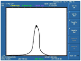
수신기에 전력을 무선으로 전송하는 송신기에 대한 고 Q 대 저 Q 구성들의 성능에 대하여, 다음의 입증이 예시적일 수도 있다. 도 9 는 일 예시적인 구현에 따른, 무선 전력 스루풋이 측정되는 동안의 1 차 공진기 및 2 차 공진기의 복수의 포지션들을 예시한다. 도 9 는 내장 (built-in) 추적 생성기를 갖는 스펙트럼 분석기 (902) 를 포함한다. 추적 생성기는 주파수 대역에 걸쳐 스윕되는 일정한 진폭 신호를 생성할 수도 있다. 스펙트럼 분석기 (902) 는 대역에 걸쳐 수신기 (예를 들어, 공진기 (906)) 를 스윕함으로써 신호를 측정한다. 스펙트럼 분석기 (902) 는 분석기 디스플레이의 중심에 설정된 동작 주파수와 함께 진폭 대 주파수를 디스플레이할 수도 있다. 시작 및 정지 주파수들 및 스윕핑은 추적 생성기와 스펙트럼 분석기 (902) 사이에 동기화될 수도 있다. 네트워크 분석기는 주파수의 함수로서 전기 네트워크들을 측정하기 위해 신호 소스 및 분석기와 유사한 기기이다. 스펙트럼 분석기 (902) 는 또한 네트워크 분석기를 포함할 수도 있다. 입증은 다음과 같이 구성된다. 추적 생성기의 출력 (922) 은 고품질 커패시터 (미도시) 에 연결된 인쇄 회로 코일을 포함하는 제 1 공진기 (904) 에 커플링된다. 제 1 공진기와 동일한 제 2 공진기 (906) 는 스펙트럼 분석기 입력 (924) 에 커플링된다. 제 1 (904) 및 제 2 (906) 공진기들은 각각 동일한 중심 주파수로 튜닝되고 198 의 측정된 고유 또는 언로딩된 Q 를 갖는다. 이 실험을 위해, 제 1 (904) 및 제 2 (906) 공진기들은 직경이 6 인치인 와이어의 4 개의 턴들을 각각 갖는 코일들을 포함한다.For the performance of high Q vs. low Q configurations for transmitters that transmit power wirelessly to the receiver, the following proof may be exemplary. FIG. 9 illustrates a plurality of positions of a primary resonator and a secondary resonator during wireless power throughput measurements, in accordance with one exemplary implementation. Figure 9 includes a
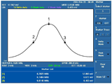
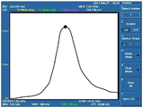
2 개의 구성들은 커플링에 의해 단지 다른 것으로 테스트되었다. 예를 들어, 소스 (예를 들어, 추적 생성기) 로부터 1 차 공진기에의 커플링은 고 Q 테스트의 경우 매우 루스하고 저 Q 테스트의 경우 매우 타이트한 것으로 설정되었다. 도 10 및 도 11 은 로딩된 Q 를 결정하기 위한 고 Q 및 저 Q 테스트에 대한 전력 스루풋 대 주파수를 각각 도시한다.The two configurations were tested by coupling only to be different. For example, coupling from a source (e.g., a trace generator) to the primary resonator was set to very loose for high Q tests and very tight for low Q tests. Figures 10 and 11 show the power throughput versus frequency for the high Q and low Q tests to determine the loaded Q, respectively.
도 10 은 일 예시적인 구현에 따른, 고 로딩된 Q 1 차 대 2 차 공진기 전력 전송 셋업을 위한 전력 스루풋 대 주파수를 예시한다. 도시한 바와 같이, 중심 주파수 (fc) 는, 숫자 "1" 로 나타낸 바와 같이, 6.78MHz 에 있고, 하위 컷오프 주파수 (flower) 는, 숫자 "2" 로 나타낸 바와 같이, 6.74MHz 에 있고, 상위 컷오프 주파수 (fupper) 는, 숫자 "3" 으로 나타낸 바와 같이, 6.81MHz 에 있다. 이들 결과들은 이하 표 1 에 요약된다.10 illustrates power throughput versus frequency for a heavily loaded Q primary-to-secondary resonator power transfer setup, in accordance with one exemplary implementation. As shown in the figure, the center frequency f c is 6.78 MHz as indicated by the numeral "1" and the lower cutoff frequency f lower is 6.74 MHz as indicated by the numeral "2" The upper cutoff frequency (f upper ) is at 6.81 MHz, as indicated by the number "3 ". These results are summarized in Table 1 below.
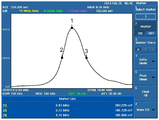
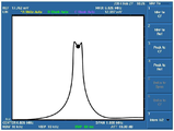
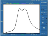
도 11 은 일 예시적인 구현에 따른, 낮은 로딩된 Q 1 차 대 2 차 공진기 전력 전송 셋업을 위한 전력 스푸풋 대 주파수를 예시한다. 도시한 바와 같이, 중심 주파수 (fc) 는, 숫자 "1" 로 나타낸 바와 같이, 6.12MHz 에 있고, 하위 컷오프 주파수 (flower) 는, 숫자 "2" 로 나타낸 바와 같이, 6.93MHz 에 있고, 그리고 상위 컷오프 주파수 (fupper) 는, 숫자 "3" 으로 나타낸 바와 같이, 8.16MHz 에 있다. 이들 결과들은 이하 표 1 에 또한 요약된다.FIG. 11 illustrates a power spread versus frequency for a low loaded Q primary-to-secondary resonator power transfer setup, in accordance with one exemplary implementation. As shown, the center frequency f c is at 6.12 MHz and the lower cutoff frequency f lower is 6.93 MHz, as indicated by the numeral "2 " And the upper cutoff frequency f upper is at 8.16 MHz, as indicated by the number "3 ". These results are also summarized in Table 1 below.
루스한 (예를 들어, 고 Q) 및 타이트한 (예를 들어, 저 Q) 커플링들의 측정된 응답들이 이하 표 1 에 요약된다. 루스한 커플링은 고 로딩된 Q 를 초래하는 한편, 타이트한 커플링은 훨씬 더 저 로딩된 Q 값을 초래한다.The measured responses of loose (e.g., high Q) and tight (e.g., low Q) couplings are summarized in Table 1 below. Loose coupling results in a heavily loaded Q, while tight coupling results in a much lower loaded Q value.

전력 스루풋의 입증은 3 개의 스테이지들에서 수행되었다. 3 개의 스테이지들의 각각에서, 공진기들 (904/906) 은 멀리 떨어져 포지셔닝되기 시작하고 복수의 연속적인 측정들의 각각에 대해 서로 더 가깝게 이동되고, 그 포지션들은 도 9 에 도시한 바와 같이 점선들 (910, 912, 914, 916, 918 및 920) 의 적어도 서브세트에 의해 표현된다. 스크린의 상부에 더 가까운 응답은 더 높은 스루풋을 나타낸다. 스크린의 하부에 더 가까운 응답은 더 낮은 스루풋을 나타낸다. 제 1 스테이지는 주파수가 피크 공진 주파수 (ωc 또는 fc) 에서 일정하게 유지되는 고 Q 구성의 테스트를 예시한다. 제 2 스테이지는 주파수가 특정한 대역폭에 걸쳐 스윕되는 고 Q 구성의 테스트를 예시한다. 제 3 스테이지는 주파수가 특정한 대역폭에 걸쳐 스윕되는 저 Q 구성의 테스트를 예시한다.Evidence of power throughput was performed in three stages. In each of the three stages, the resonators 904/906 begin to be positioned farther away and are moved closer to each other for each of a plurality of successive measurements, the positions of which are shown by dashed
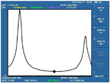
도 12a 내지 도 12f 는 일 예시적인 구현에 따른, 루스하게 커플링될 때 도 9 의 1 차 공진기와 2 차 공진기 사이의 여러 상이한 분리들을 위한 중심 주파수에서의 전력 스루풋을 예시한다. 도 12a 에 의해 도시한 바와 같이, 제 1 스테이지에서, 제 1 및 제 2 공진기들이 도 9 의 포지션 (910) 에 대응하여, 대략 30 센티미터 떨어져 유지될 때, 응답은 양호한 스루풋을 나타내는 스크린의 중간 부근에 있다. 제 1 및 제 2 공진기들이 도 9 의 포지션 (912) 에 대응하여, 대략 25cm 떨어져 있는 것으로 조정되는 도 12b 에서, 응답은 위로 가고, 이는 도 12a 의 30cm 분리와 비교하여 더 나은 스루풋을 나타낸다. 도 12c 에서, 제 1 및 제 2 공진기들은 도 9 의 포지션 (914) 에 대응하여, 대략 20cm 떨어져 있고, 응답은 각각 도 12a 및 도 12b 의 30cm 또는 25cm 분리들 중 어느 하나와 비교하여 강하한다. 도 12d 에서, 제 1 및 제 2 공진기들은 도 9 의 포지션 (916) 에 대응하여, 대략 10cm 의 분리로 조정되고, 응답은 또 다시 강하한다. 유사하게, 도 12e 및 도 12f 에서, 제 1 및 제 2 공진기들은 도 9 의 포지션들 (918 및 920) 에 대응하여, 각각 대략 5cm 및 0cm 의 분리들로 조정된다. 도시한 바와 같이, 응답은 제 1 및 제 2 공진기들이 함께 더 가깝게 조정될 때 계속 강하한다.12A-12F illustrate power throughput at a center frequency for several different separations between the primary resonator and the secondary resonator of FIG. 9 when loosely coupled, in accordance with one exemplary implementation. As shown by Fig. 12A, in the first stage, when the first and second resonators are held approximately 30 centimeters apart, corresponding to the
더 가까운 분리들에서 제 1 및 제 2 공진기들을 유지하면 더 나은 커플링을 부여할 것이다. 도 13a 내지 도 13f 는 공진기들이 서로 더 밀접하게 이동될 때 피크 공진 주파수 (ωc 및 fc) 에서의 응답이 열화해야 하는 이유를 기술한다. 도 13a 내지 도 13f 의 각각에서, 주파수는 도 9 에 도시한 바와 같이 제 1 공진기와 제 2 공진기 사이의 상기 언급된 분리들의 각각을 위해 대역폭에 걸쳐 스윕된다.Maintaining the first and second resonators in closer separations will give better coupling. Figure 13a to Figure 13f will be described the reason why the response at the peak resonant frequency (ω c and f c) have deteriorated when the resonator are moved to each other more closely. In each of Figures 13A-13F, the frequency is swept across the bandwidth for each of the above-mentioned separations between the first resonator and the second resonator, as shown in Figure 9.
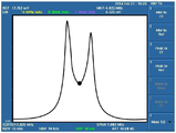
도 13a 내지 도 13f 는 일 예시적인 구현에 따른, 루스하게 커플링될 때 도 9 의 1 차 공진기와 2 차 공진기 사이의 분리들을 위한 주파수 대역폭에 걸친 전력 스루풋을 예시한다. 도 13a 내지 도 13f 에 대한 제 1 공진기와 제 2 공진기 사이의 분리들은 주파수가 상기 도 10 과 관련하여 설명한 바와 같이 측정된 fupper 및 flower 에 대응하는 주파수 대역폭에 걸쳐 스윕되었을 때 전력 스루풋이 측정된 것을 제외하고는, 도 12a 내지 도 12f 에 대한 것들에 각각 대응할 수도 있다. 도 13a 내지 도 13f 의 각각에서, 중심 주파수 (fc) 는 응답 곡선들에서 점들로 도시된다. 도 13a 에서, 응답은 양호한데, 이는 단일 피크를 나타낸다. 도 13b 에서, 1 차 및 2 차 공진기들 사이의 거리가 감소함에 따라 응답은 예상대로 증가한다. 도 13c 에서, 응답은 실질적으로 중심 주파수 (fc) 의 어느 한 쪽에서 2 개의 피크들로 스플리팅한다. 이것은 스루풋이 측면 피크들에서 증가하게 하지만 중심 주파수 (fc) 에서 감소하게 한다. 제 1 및 제 2 공진기들이 도 13d 내지 도 13f 의 각각에서 도시한 바와 같이, 서로 점점 더 가깝게 이동됨에 따라, 응답 피크들은 동작 주파수에서의 스루풋이 도 13f 에서 거의 0 으로 강하하기 때문에 중심 주파수 (fc) 에서 계속 점점 더 멀리 스플리팅한다. 이 조건은 종종 중심 주파수 (fc) 의 시프트와 혼동된다. 그러나, 도 13a 내지 도 13f 에 도시한 바와 같이, 중심 주파수는 크게 시프트하지 않는다. 그 대신에, 최고 전력 스루풋은 2 개의 피크들로 스플리팅한다. 2 개의 피크들로 스플리팅하는 피크 스루풋은 제 1 공진기와 제 2 공진기 사이의 오버 커플링의 조건을 나타낸다. 도 13a 내지 도 13f 에 도시한 바와 같이, 스플릿의 크기 (예를 들어, 스플릿 피크들 사이의 주파수 차이) 는 오버 커플링의 정도에 의존한다. 더욱이, 오버 커플링 동안의 스플릿 피크들 중 하나에서 동작하는 것은 고도 리액티브 로드를 드라이빙하는 것을 요구할 수도 있으며, 이는 고순환 전류들, 고손실들, 및 불충분한 동작을 생성할 수도 있다.13A-13F illustrate power throughput over a frequency bandwidth for separations between the primary resonator and the secondary resonator of FIG. 9 when coupled loosely, in accordance with one exemplary implementation. The separations between the first resonator and the second resonator for Figs. 13A-13F are obtained when the power throughput is measured when the frequency is swept over the frequency bandwidth corresponding to f upper and f lower measured as described above with respect to Fig. 10 12A to 12F, respectively, except for the fact that it is the same as that shown in Fig. In each of Figs. 13a through 13f, the center frequency (f c) is shown in the response curve with dots. In Figure 13A, the response is good, indicating a single peak. In Fig. 13B, the response increases as expected as the distance between the primary and secondary resonators decreases. In Fig. 13C, the response splits into two peaks at substantially one of the center frequencies f c . This causes the throughput to increase at the side peaks but to decrease at the center frequency (f c ). As the first and second resonators move closer and closer to each other, as shown in each of FIGS. 13d-13f, the response peaks are centered at the center frequency f c ) continue to splice farther and further. This condition is often confused with the shift of the center frequency (f c ). However, as shown in Figs. 13A to 13F, the center frequency does not largely shift. Instead, peak power throughput splits into two peaks. The peak throughput splitting into two peaks represents the condition of over-coupling between the first and second resonators. As shown in Figures 13A-13F, the size of the split (e.g., the frequency difference between the split peaks) depends on the degree of over-coupling. Moreover, operating at one of the split peaks during overcoupling may require driving a highly reactive rod, which may produce high circulating currents, high losses, and insufficient operation.
도 14a 내지 도 14d 는 일 예시적인 구현에 따른, 타이트하게 커플링될 때 도 9 의 1 차 공진기와 2 차 공진기 사이의 분리들을 위한 주파수 대역폭에 걸친 전력 스루풋을 예시한다. 제 1 내지 제 4 스크린들은 도 9 의 포지션들 (914, 916, 918 및 920) 에 각각 대응하고, 각각 대략 15cm, 10cm, 5cm 및 0cm 의 분리 거리들에서 저 Q 어레인지먼트를 도시한다. 도 14a 내지 도 14d 는 주파수가 상기 도 11 과 관련하여 설명한 바와 같이 측정된 fupper 및 flower 에 대응하는 주파수 대역폭에 걸쳐 스윕되었을 때 측정된 전력 스루풋을 나타내고, 여기서 중심 주파수 (fc) 는 각각 응답 곡선들 상에 점들로 나타내진다. 도시한 바와 같이, 보다 저 Q 구성은 제 1 공진기와 제 2 공진기 사이의 더 먼 분리들에서 고 Q 구성만큼 높은 스루풋을 제공하지 않는다. 도 14a 에서, 응답은 스크린 중간에 근접해 있다. 도 14b 에서, 응답은 스크린의 상부에 근접한, 도 14a 의 것보다 더 강하다. 도 14c 에서, 응답은 여전히 상대적으로 강하지만, 응답은 스플리팅하기 시작한다. 도 14d 에서, 응답은 더욱 스플리팅하였다. 그러나, 동작 주파수 (fc) 에서의 스루풋은 여전히 상대적으로 높다. 따라서, 도 14c 및 도 14d (뿐만 아니라 도 13c 내지 도 13f) 는 제 1 및 제 2 공진기들이 오버-커플링의 조건에서 전송중인 무선 전력 전송을 도시한다.14A-14D illustrate power throughput over a frequency bandwidth for separations between the primary resonator and the secondary resonator of FIG. 9 when tightly coupled, in accordance with one exemplary implementation. The first through fourth screens correspond to the
상기 예시로부터, 동작 주파수를 스플릿 응답의 피크들 중 하나로 단순히 리튜닝하는데 직관적인 것으로 보일 수도 있다. 그러나, 동작 주파수가 재조정될 때, 피크들은 그 재조정하는 것이 동작 조건들을 변화시키기 때문에 조정을 따르는 경향이 있다. 동작 주파수를 피크들 중 하나로 리튜닝하는 것은 예를 들어, 배터리가 충전되고 로드가 변화할 때 또는 심지어 제 1 공진기와 제 2 공진기 사이의 분리 거리에서의 작은 변화들이 발생할 때, 회로 조건들이 바뀜에 따라 주파수 단위로 피크를 추격하는 제어 시스템을 초래할 것이다. 추가로, 오버-커플링 동안 스플릿 피크들 중 하나에서 동작하는 것은 고도 리액티브 로드를 드라이빙하는 것을 요구한다. 리액티브 로드들은 로드에 전력을 전달하지 않는 손실들을 야기하는 고 순환 전류들을 생성하여, 비효율적인 동작을 야기한다. 이런 이유로, 리액티브 로드들을 제거하기 위하여 가능한 한 단위 역률 (unity power factor) 에 가깝게 (예를 들어, 중심 주파수 (fc) 에 가깝게) 시스템을 동작시키는 것이 바람직하다. 그것이 나타남에 따라, 단지 트루 공진 포인트에서의 동작만이 단위에 가까운 역률을 제공하는 것이 가능하다. 소스와 제 1 공진기 사이, 제 1 공진기와 제 2 공진기 사이, 그리고 제 2 공진기와 로드 사이의 커플링을 조정하는 것은 임계 커플링을 가진 트루 공진 포인트 (예를 들어, 피크가 스플리팅하기 시작하기 전의 최대 커플링의 포인트) 에서 동작을 허용한다. 임계 커플링 시에, 로드는 커플링된 공진기들의 변압기 액션을 통하여, 소스에 적절히 반영되고, 역률은 거의 단위이며, 시스템은 전력 스루풋 대역폭에 있어서 단 하나의 피크가 존재하기 때문에 안정되어 있다.From the above example, it may seem intuitive to simply retune the operating frequency to one of the peaks of the split response. However, when the operating frequency is readjusted, the peaks tend to follow the adjustment because their readjustment changes operating conditions. Retuning the operating frequency to one of the peaks can be achieved, for example, when the battery is charged and the load changes, or even when small changes occur in the separation distance between the first resonator and the second resonator, Thus leading to a control system that tracks the peak in frequency units. Additionally, operating at one of the split peaks during over-coupling requires driving the highly reactive rod. Reactive rods produce high circulating currents that cause losses that do not deliver power to the load, resulting in inefficient operation. For this reason, it is desirable to operate the system as close to unity power factor as possible (e.g. close to the center frequency (f c )) to eliminate reactive loads. As it appears, it is possible for only the operation at the true resonance point to provide a power factor close to the unit. Adjusting the coupling between the source and the first resonator, between the first resonator and the second resonator, and between the second resonator and the load may be accomplished by using a true resonant point with a critical coupling (e.g., Lt; / RTI > point of maximum coupling before < RTI ID = 0.0 > At critical coupling, the load is properly reflected at the source through the transformer action of the coupled resonators, the power factor is near the unit, and the system is stable because there is only one peak in the power throughput bandwidth.
도 10 내지 도 14d 의 이전의 논의로부터, 고 Q 동작이 큰 분리 거리들에서 낮은 Q 동작보다 더 높은 스루풋을 제공하지만 더 작은 분리 거리들에서 훨씬 덜 효율적으로 수행하는 것이 보여질 수 있다. 따라서, 고 Q 동작은 단지 상대적으로 큰 공진기 분리 거리들의 좁은 범위에 걸쳐 유용하다. 추가로, 고 Q 동작 하에서, 공진은 거리, 정렬, 주파수, 로딩 조건들 또는 인근 오브젝트들의 변화들에 의해 취약하고 용이하게 업셋된다. 그에 반해서, 저 Q 동작은 넓고 안정된 동작을 제공하고 1/2 공진기 코일 직경과 0 사이의 분리 거리들을 위한 고 Q 동작보다 더 높은 스루풋 및 공진 안정성을 제공한다.It can be seen from the previous discussion of Figures 10-14d that high Q operation provides higher throughput than low Q operation at large separation distances but much less efficiently at smaller separation distances. Thus, high Q operation is only useful over a narrow range of relatively large resonator separation distances. Additionally, under high Q operation, the resonance is weak and easily upset by changes in distance, alignment, frequency, loading conditions or nearby objects. In contrast, low Q operation provides a wide and stable operation and provides higher throughput and resonant stability than high Q operation for half resonator coil diameters and separation distances between zero.
상기 입증에서 나타낸 바와 같이, 가능한 한 효율적으로 전력 소스로부터 로드로 에너지를 커플링하는 목표는 그것이 보이는 것만큼 단순하지 않다. 보다 타이트한 커플링은 시스템을 가까운 공진기 분리 거리에서 보다 효율적이고 안정되게 하지만, 더 큰 분리에 반대의 효과를 가져올 것이다. 보다 루스한 커플링은 더 먼 분리에서 작동하지만 더 가까운 분리에서 매우 빠르게 실패한다.As indicated in the above proof, the goal of coupling energy from the power source to the load as efficiently as possible is not as simple as it seems. Tighter coupling will make the system more efficient and stable at near resonator separation distances, but will have the opposite effect of larger separation. A loose coupling works at a farther separation but fails very quickly at closer separation.
충전가능한 디바이스의 유도 공진 무선 충전을 위한 시스템에 대하여, 그 시스템은 4 개의 변수들 1) 전력 소스로부터 1 차 공진기로의 커플링, 2) 제 1 공진기와 제 2 공진기 사이의 공기 커플링, 3) 2 차 공진기로부터 로드로의 커플링, 및 4) 로드로 브레이크 다운될 수도 있다. 공기 커플링 및 로드는 시스템의 제어 하에 있지 않다. 예를 들어, 충전될 디바이스 (예를 들어, 차량) 는 이동될 수도 있거나 또는 배터리는 풀 용량으로 점차 충전될 수도 있으며, 이들 각각은 로드를 변화시킬 수도 있다. 따라서, 전력 소스와 1 차 공진기 사이의 커플링 및 2 차 공진기와 로드 사이의 커플링은 시스템에 의해 제어될 수도 있고 최대 효율을 위해 시스템의 동작을 조정하기 위한 주요한 제어 포인트들이다.For a system for inductive resonant charging of a rechargeable device, the system comprises four variables: 1) coupling from a power source to a primary resonator, 2) air coupling between the first resonator and the second resonator, 3 ) Coupling from the secondary resonator to the load, and 4) the rod. Air coupling and load are not under system control. For example, the device to be charged (e.g., a vehicle) may be moved or the battery may be gradually charged to full capacity, each of which may vary the load. Thus, the coupling between the power source and the primary resonator and the coupling between the secondary resonator and the load may be controlled by the system and are the primary control points for adjusting the operation of the system for maximum efficiency.
매 공기 커플링 팩터 및 로드 조건에 대해, 시스템의 임계 커플링 및 가장 효율적인 전력 전송을 초래하는 조정가능한 커플링들의 조합이 존재할 수도 있다. 전력 소스와 1 차 공진기 사이의 커플링과 2 차 공진기와 로드 사이의 커플링 양자가 공기 커플링에 영향을 주기 때문에 1 차 측 커플링 또는 2 차 측 커플링 만을 변화시키는 것은 임계 커플링을 생성하기 위한 최적의 동작 포인트로 시스템을 튜닝하는데 충분하지 않을 수도 있으므로 전력 소스로부터 1 차 공진기로의 그리고 2 차 공진기로부터 로드로의 양자의 커플링은 공기 커플링 또는 로드 중 어느 하나가 변화할 때, 조정되는 것이 바람직하다.For every air coupling factor and load condition, there may be a combination of critical coupling of the system and adjustable couplings leading to the most efficient power transfer. Changing both the primary-side coupling or the secondary-side coupling only because the coupling between the power source and the primary resonator and the coupling between the secondary resonator and the rod affect the air coupling creates a critical coupling Coupling of both from the power source to the primary resonator and from the secondary resonator to the load may occur when either the air coupling or the load changes, Is preferably adjusted.
일부 구현들에서, 전력 소스 및/또는 로드 임피던스들의 변동은 조정가능한 커플링의 일부일 수 있다. 추가적으로, 전력 소스가 1 차 공진기에 제시하는 임피던스 또는 로드가 2 차 공진기에 제시하는 임피던스를 변화시키는 방법들이 유용할 수도 있다. 그러나, 이들 방법들은 조정의 범위 또는 레졸루션에 있어서 제한되는 경향이 있다. 이에 따라, 소스/로드 임피던스의 변동은 원하는 동작 조건들을 커버하는데 충분하지 않을 수도 있다. 일부 저 Q 구현들에서, 로딩 또는 공기 커플링의 변동은 1 차 공진기로의 전력 소스의 드라이브를 조정함으로써 보상될 수도 있는데, 이는 상기 설명된 소스 임피던스의 조정보다 훨씬 더 제한될 수도 있다. 따라서, 일부 고 Q 동작 구현들에서, 단대단으로부터 임계 커플링을 달성하기 위하여 전력 소스와 1 차 공진기 사이 및 2 차 공진기와 로드 사이의 커플링을 조정할 필요성이 존재할 수도 있다. 이에 따라, 일부 구현들에서, 이를 테면 이하의 도 15 에 예시된 구현에서, 실제 고 Q 무선 전력 전송 시스템들은 전력 소스와 1 차 공진기 사이의 커플링 및 2 차 공진기와 로드 사이의 커플링의 조정을 코디네이션할 수도 있다.In some implementations, the variation of the power source and / or load impedances may be part of the adjustable coupling. Additionally, methods may be useful in which the impedance presented by the power source to the primary resonator or the impedance that the load presents to the secondary resonator. However, these methods tend to be limited in scope or resolution of adjustment. Accordingly, variations in the source / load impedance may not be sufficient to cover desired operating conditions. In some low Q implementations, variations in loading or air coupling may be compensated by adjusting the drive of the power source to the primary resonator, which may be much more limited than the adjustment of the source impedance described above. Thus, in some high Q operation implementations, there may be a need to adjust the coupling between the power source and the primary resonator and between the secondary resonator and the load to achieve critical coupling from the far-end. Thus, in some implementations, such as in the implementation illustrated in FIG. 15 below, actual high Q power transmission systems may include coupling between the power source and the primary resonator and coupling between the secondary resonator and the load May be coordinated.
도 15 는 일 예시적인 구현에 따른, 1 차 및 2 차 측 커플링 조정 능력을 갖는 무선 전력 전송 시스템 (1500) 의 기능적 블록 다이어그램이다. 시스템 (1500) 은 1 차, 충전 또는 송신기 측 (1502) 및 2 차, 충전가능 또는 수신기 측 (1504) 을 포함할 수도 있다. 송신기 측 (1502) 은 1 차 공진기 (1516) 에 커플링될 수도 있는 커플링 회로 (1508) 에 연결된 전력 소스 (1506) 를 포함할 수도 있다. 송신기 측 (1502) 은 커플링 회로 (1508), 센서 회로 (1514) 및 통신 회로 (1512) 의 각각에 연결된 제어기 회로 (1510) 를 더 포함할 수도 있다. 센서 회로 (1514) (예를 들어, 전류 센서, 전압 센서, 전력 센서, 로드 센서, 전압 또는 전류 위상 센서) 는 1 차 공진기 (1516) 에 커플링되는 전력 스루풋의 적어도 하나의 파라미터를 측정하도록 구성될 수도 있다. 수신기 측 (1504) 은 정류기 회로 (1530) 및 제어기 회로 (1524) 에 연결되는 커플링 회로 (1528) 에 커플링된 2 차 공진기 (1518) 를 포함할 수도 있다. 정류기 회로 (1530) 는 로드 (1532) (예를 들어, 배터리 또는 충전가능한 차량 내의 다른 충전 회로) 에 연결될 수도 있다. 제어기 회로 (1524) 는 통신 채널 (1520) 을 통해 송신기 측 (1502) 의 통신 회로 (1512) 와 통신하도록 구성될 수도 있는 통신 회로 (1526) 및 센서 회로 (1522) 에 추가로 연결될 수도 있다. 센서 회로 (1522) 는 2 차 공진기 (1518) 로부터 커플링되는 전력 스루풋의 적어도 하나의 파라미터를 측정하도록 구성될 수도 있다.15 is a functional block diagram of a wireless
일부 구현들에 따르면, 전력 소스 (1506) 와 1 차 공진기 (1516) 사이의 커플링 회로 (1508) 뿐만 아니라 2 차 공진기 (1518) 와 정류기 회로 (1530) 와 로드 (1532) 사이의 커플링 회로 (1528) 는 특히, 1 차 (1516) 및 2 차 (1518) 공진기들이 유사한 구성인 경우 동시에 조정될 수도 있다. 조정들은 송신기 측 (1502) 의 제어기 회로 (1510) 와 수신기 측 (1504) 의 제어기 회로 (1524) 사이에서 통신 채널 (1520) 을 통해 코디네이션될 수도 있다. 센서 회로들 (1514 및 1522) 은 각각 송신기 측 (1502) 및 수신기 측 (1504) 에서의 조건들을 감지하고, 감지된 조건들에 관한 정보를 적어도 각각의 제어기 회로들 (1510 및 1524) 에 통신할 수도 있다.According to some implementations, the
일부 구현들에서, 송신기 측 (1502) 이 마스터 제어기인 (예를 들어, 1 차 측 커플링의 코디네이션된 조정을 직접적으로 제어하고 2 차 측 커플링들의 조정을 간접적으로 제어하는) 경우, 송신기 측 제어기 회로 (1510) 는 1 차 공진기 (1516) 에 커플링되는 전력의 파라미터들을 결정하기 위해 센서 회로 (1514) 로부터 제 1 입력을 수신할 수도 있다. 이러한 파라미터들은 전압, 전류, 실제 전력 (real power) (Watts), 무효 전력 (Volt-Amperes), 전압과 전류 사이의 위상각, 센싱 컴포넌트 (예를 들어, 저항기, 커패시터, 인덕터 등) 에 걸리는 전압 강하, 전류 변압기로부터의 전류 또는 전력의 임의의 다른 측정치를 포함할 수도 있지만 이들에 제한되지는 않는다. 마찬가지로, 수신기 측 제어기 회로 (1524) 는 2 차 공진기 (1518) 로부터 커플링되는 전력의 파라미터들을 결정하기 위해 센서 회로 (1522) 로부터 제 1 입력을 수신할 수도 있다. 이러한 파라미터들은 전압, 전류, 실제 전력 (Watts), 무효 전력 (Volt-Amperes), 전압과 전류 사이의 위상각, 센싱 컴포넌트 (예를 들어, 저항기, 커패시터 또는 인덕터) 에 걸리는 전압 강하, 전류 변압기로부터의 전류 또는 전력의 임의의 다른 측정치를 포함할 수도 있지만 이들에 제한되지는 않는다.In some implementations, when the
제어기 회로 (1510) 는 무선 통신 채널 (1520) 을 통해 (또는 1 차 공진기에 의해 통신하도록 생성된 자기장을 이용하여 대역-내 채널을 통해) 통신 회로 (1526) 로 통신을 전송하여, 수신기 측 (1504) 상에서 센서 회로 (1522) 에 의해 센싱된 전력 파라미터들의 표시를 요청할 것을 통신 회로 (1512) 에 지시할 수도 있다. 대안으로, 제어기 회로 (1524) 는 통신 채널 (1520) 을 통해 통신 회로 (1512) 에 센서 회로 (1522) 에 의해 센싱된 전력 파라미터들의 표시를 송신할 것을 통신 회로 (1526) 에 자율적으로 지시할 수도 있다. 일단 수신되면, 그 표시는 통신 회로 (1512) 로부터 제어기 회로 (1510) 로 포워딩될 수도 있다. 제어기 회로 (1510) 는 그 후 커플링 회로 (1508) 가 센서 회로들 (1514 및 1522) 로부터의 상기 설명된 표시들에 따른 전력 스루풋에 기초하여 증가 (타이트닝) 되어야 하는지 또는 감소 (루스닝) 되어야 하는지를 결정할 수도 있다. 제어기 회로 (1510) 는 송신기 측 (1502) 상에서 커플링 회로 (1508) 를 직접 제어할 수도 있다. 제어기 회로 (1510) 는 또한, 특정한 방향으로 커플링 회로 (1528) 를 조정할 것을 제어기 회로 (1524) 에 명령하는 하나 이상의 메시지들을 통신 채널 (1520) 을 통해 통신 회로 (1526) 에 송신하도록 통신 회로 (1512) 를 구성함으로써 수신기 측 (1504) 의 커플링 회로 (1528) 를 간접적으로 제어할 수도 있다.Controller circuitry 1510 transmits communications to
연속적인 제어 사이클에서, 제어기 회로 (1510) 는 상기 설명된 방식으로 통신 회로 (1512) 에 의하여 통신 회로 (1526) 를 통해 센서 회로 (1522) 로부터 그리고 센서 회로 (1514) 로부터 표시들의 제 2 세트를 수신할 수도 있다. 제어기 회로 (1510) 는 그 후 이전 표시들의 세트 뿐만 아니라 현재의 표시들의 세트를 활용하여, 전력 스루풋이 개선되었는지 또는 열화되었는지를 결정할 수도 있다. 표준 제어 루프 기법들을 이용하여, 제어기 회로 (1510) 는 센서 회로들 (1522) 로부터의 표시들의 수신 및 커플링 회로들 (1508 및 1528) 의 조정을 반복하여 최적의 동작 포인트로 조정하고 그 후 최적의 동작 포인트를 유지할 수도 있다.In a continuous control cycle, the controller circuit 1510 receives a second set of indications from the
예시적인 제어 루프 기법들은 비례, 적분, 비례-미분 (PD), 비례-적분 (PI), 비례-적분-미분 (PID) 제어, 히스테리시스, 불감대, 댐핑, 세트 포인트 램핑, 피드-포워드, 게인 스케줄링, 적분 디스에이블링, 적분 바운딩, 퍼지 로직, 또는 임의의 다른 루프 제어 기법 또는 최적화를 포함할 수도 있다. 일부 구현들에서, 이 무선 전력 전송 제어는 로드 제어 및/또는 전력 소스 제어와 추가로 코디네이션될 수도 있다. 이러한 코디네이션은 시스템의 어딘가의 스텝 변화들로 인한 시스템의 열화를 회피할 수도 있다. 이 코디네이션은 시스템 파라미터들 또는 동작의 변화를 더 잘 핸들링하기 위해 상기 언급된 기법들에 의해 제어 루프의 최적화들을 트리거링할 수도 있다.Exemplary control loop techniques include, but are not limited to, proportional, integral, proportional-differential (PD), proportional-integral (PI), proportional-integral-derivative (PID) control, hysteresis, deadband, damping, setpoint ramping, Scheduling, integral disabling, integral bounding, fuzzy logic, or any other loop control technique or optimization. In some implementations, the wireless power transmission control may be further coordinated with load control and / or power source control. This coordination may avoid system degradation due to step changes somewhere in the system. This coordination may trigger optimizations of the control loop by the above-mentioned techniques to better handle changes in system parameters or operations.
일부 대안적 구현들에서, 수신기 측 (1504) 이 1 차 및 2 차 측 커플링들의 코디네이션된 조정을 제어하는 경우, 제어기 회로 (1510), 센서 회로 (1514) 및 통신 회로 (1512) 의 상기 설명된 액션들은 제어기 회로 (1524), 센서 회로 (1522) 및 통신 회로 (1526) 의 액션들과 각각 스왑될 수도 있고 그 역도 또한 마찬가지이다.In some alternate implementations, the controller circuit 1510, the
상기 구현들은 1 차 및 2 차 공진기들의 사이즈들 및 구성이 유사할 때 유리하다. 구현들은 단순하고, 빠르며 가장 적은 수의 통신을 요구한다. 1 차 및 2 차 공진기들의 사이즈들 및 구성들이 유사하지 않으면, 다음의 구현들이 유리할 수도 있다.These implementations are advantageous when the sizes and configurations of the primary and secondary resonators are similar. Implementations are simple, fast, and require the least number of communications. If the sizes and configurations of the primary and secondary resonators are not similar, the following implementations may be advantageous.
송신기 측 (1502) 이 1 차 및 2 차 측 커플링들의 코디네이션된 조정을 제어하는 경우, 송신기 측 제어기 회로 (1510) 는 1 차 공진기 (1516) 에 커플링되는 전력의 파라미터들을 결정하기 위해 센서 회로 (1514) 로부터 제 1 입력을 수신할 수도 있다. 수신기 측 제어기 회로 (1524) 는 마찬가지로 2 차 공진기 (1518) 로부터 커플링되는 전력의 파라미터들을 결정하기 위해 센서 회로 (1522) 로부터 제 1 입력을 수신할 수도 있다. 예를 들어, 제어기 회로 (1510) 는 제어기 회로 (1524) 가 2 차 공진기 (1518) 로부터 통신 회로 (1512) 에 커플링되는 전력의 파라미터들의 표시를 전송하도록 통신 회로 (1526) 를 구성하는 것을, 무선 통신 채널 (1520) 을 통해 요청하도록 통신 회로 (1512) 를 구성할 수도 있다. 일부 대안적 구현들에서, 제어기 (1524) 는 제어기 회로 (1510) 로 포워딩될 표시를 통신 채널 (1520) 을 통해 통신 회로 (1512) 로 전송하도록 통신 회로 (1526) 를 자율적으로 구성할 수도 있다. 제어기 회로 (1510) 는 그 후, 커플링 회로 (1508) 가 증가 (타이트닝) 되어야 하는지 또는 감소 (루스닝) 되어야 하는지를 결정할 수도 있다. 이러한 구현들에서, 제어기 회로 (1510) 는 송신기 측 (1502) 상에서 커플링 회로 (1508) 에 직접 커맨드할 수도 있다.If the
제어기 회로 (1510) 는 그 후 상기 설명된 방식으로 센서 회로 (1514) 및 센서 회로 (1522) 의 각각으로부터 입력들의 제 2 세트 (예를 들어, 전력 전송의 센싱된 파라미터들의 표시들) 를 수신할 수도 있다. 제어기 회로 (1510) 는 전력 전송이 개선되었는지 또는 열화되었는지를 입력들의 제 1 및 제 2 세트들 (예를 들어, 전력 전송의 센싱된 파라미터들의 표시들) 로부터 결정할 수도 있다. 이전에 설명한 바와 같이, 제어기 (1510) 는 제어기 회로 (1524) 가 수신기 측 (1504) 상의 커플링 회로 (1528) 를 조정하게 하기 위해 통신 채널 (1520) 을 통해 커맨드 또는 메시지를 전송함으로써 수신기 측 (1504) 의 커플링 회로 (1528) 를 간접적으로 제어할 수도 있다.Controller circuit 1510 then receives a second set of inputs (e.g., indicia of sensed parameters of power transfer) from each of
제어기 회로 (1510) 는 상기 설명된 방식으로 센서 회로 (1514) 와 센서 회로 (1522) 양자로부터 입력들의 제 3 세트 (예를 들어, 전력 전송의 센싱된 파라미터들의 표시들) 를 추가적으로 수신할 수도 있다. 제어기 회로 (1510) 는 입력들의 제 2 및 제 3 세트들을 활용하여, 전력 전송이 개선되었는지 또는 열화되었는지를 결정할 수도 있다. 표준 제어 루프 기법들을 이용하여, 제어기 회로 (1510) 는 최적의 동작 포인트를 달성 및 유지하기 위해 커플링 회로 (1508) 및 커플링 회로 (1528) 를 제어할 수도 있다.Controller circuitry 1510 may additionally receive a third set of inputs (e.g., indicia of sensed parameters of power transfer) from both
일부 대안적 구현들에서, 수신기 측 (1504) 이 1 차 및 2 차 측 커플링들의 코디네이션된 조정을 제어하는 경우, 제어기 회로 (1510), 센서 회로 (1514) 및 통신 회로 (1512) 의 상기 설명된 액션들은 제어기 회로 (1524), 센서 회로 (1522) 및 통신 회로 (1526) 의 액션들과 각각 스왑될 수도 있고 그 역도 또한 마찬가지이다. 커플링 회로들 (1508 및 1528) 은 이하 도 16 내지 도 23 과 관련하여 더 상세히 설명될 바와 같이 임의의 수의 물리적 어레인지먼트들 중 하나를 포함할 수도 있다.In some alternate implementations, the controller circuit 1510, the
도 16 은 일 예시적인 구현에 따른, 가변 저항 커플링을 활용한 도 15 의 커플링 회로의 부분의 개략적 다이어그램이다. 간략화를 위해, 도 16 내지 도 23 의 각각에 대한 다음의 논의들은 커플링 회로 구현의 동일한 타입이 1 차 및 2 차 측들 양자에서 이용되고 조정이 1 차 및 2 차 측들에 행해진다는 것을 가정한다. 전력 소스와 1 차 공진기 사이 또는 2 차 공진기와 로드 사이의 조정가능한 커플링을 제공하기 위한 일부 구현들은 각각의 공진기로부터 소스 또는 로드를 분리하는 가변 저항기를 활용한다. 예를 들어, 커플링 회로 (1600) 는 1 차 또는 송신기 측 커플링 회로 및 2 차 또는 수신기 측 커플링 회로를 예시한다. 1 차 또는 송신기 측은 커패시터 (1614) 에 연결된 인덕터 (1612) 를 적어도 포함하는 1 차 공진기에 연결된 조정가능한 저항기 (1602) 를 포함할 수도 있다. 2 차 또는 수신기 측은 커패시터 (1654) 에 연결된 인덕터 (1652) 를 적어도 포함하는 2 차 공진기에 연결된 조정가능한 저항기 (1604) 를 포함할 수도 있다. 가변 저항기 (1602) 및 가변 저항기 (1604) 를 낮은 저항 값들로 조정하는 것은 소스 및 로드가 각각 무선 전력 전송 시스템의 동작 Q 를 감소시키는 것을 허용한다. 이것은 1 차 및 2 차 공진기들이 매우 근접해 있는 경우에 유리할 수도 있다. 가변 저항기들 (1602 및 1604) 을 높은 저항 값으로 조정하는 것은 1 차 및 2 차 공진기들을 각각 격리시키고 더 높은 Q 값에서의 동작을 허용한다. 이것은 공진기들이 더 멀리 떨어져 있는 경우에 유리할 수도 있다. 그러나, 저항기들을 이용하는 주요한 결점은 전력이 저항기들에서 소산되어, 효율을 낮춘다는 것이다.Figure 16 is a schematic diagram of a portion of the coupling circuit of Figure 15 utilizing variable resistance coupling, in accordance with one exemplary implementation. For simplicity, the following discussion of each of Figures 16-23 assumes that the same type of coupling circuit implementation is used in both the primary and secondary sides and that adjustments are made to the primary and secondary sides. Some implementations for providing an adjustable coupling between the power source and the primary resonator or between the secondary resonator and the load utilize variable resistors that separate the source or the load from each resonator. For example, the
도 17 은 일 예시적인 구현에 따른, 가변 리액티브 커플링을 활용한 도 15 의 커플링 회로의 부분의 개략적 다이어그램이다. 커플링 회로 (1700) 는 도 16 에 도시된 것과 유사하게, 1 차 또는 송신기 측 커플링 회로 및 2 차 또는 수신기 측 커플링 회로를 예시한다. 그러나, 도 16 에 도시된 것보다 더 효율적인 솔루션은, 조정가능한 저항기들 (1602 및 1604) 이 조정가능한 커플링으로서 활용되는 경우, 조정가능한 저항기들 (1602 및 1604) 을 각각 가변 리액티브 컴포넌트들 (예를 들어, 인덕터들 또는 커패시터들) (1702 및 1704) 로 대신할 것이다. 리액티브 컴포넌트들의 리액턴스의 크기는 동작의 주파수에서 조정가능한 저항기들 (1602 및 1604) 의 저항의 크기와 동일할 수도 있다. 1 차 또는 송신기 측은 커패시터 (1714) 에 연결된 인덕터 (1712) 를 적어도 포함하는 1 차 공진기에 연결된 조정가능한 리액티브 컴포넌트 (예를 들어, 인덕터 또는 커패시터) (1602) 를 포함할 수도 있다. 2 차 또는 수신기 측은 커패시터 (1754) 에 연결된 인덕터 (1752) 를 적어도 포함하는 2 차 공진기에 연결된 조정가능한 리액티브 컴포넌트 (예를 들어, 인덕터 또는 커패시터) (1704) 를 포함할 수도 있다. 그러나, 인덕터들 또는 커패시터들을 가변적이게 하는 것은 어려울 수도 있다. 인덕터의 탭들 간 또는 다수의 커패시터들 간의 스위칭은 이러한 구현에서 스텝-와이즈 가변 리액턴스를 제공할 수도 있다. 다른, 보다 복잡한 네트워크들의 리액티브 엘리먼트들은 조정가능한 커플링 기능 뿐만 아니라 임피던스 매칭 및 고조파 필터링을 제공하기 위해 이용될 수도 있다. 그러나, 이러한 멀티-기능 네트워크들을 가변적이게 하는 것은 증가된 복잡성 및 비용 뿐만 아니라 감소된 효율을 요구할 수도 있다.Figure 17 is a schematic diagram of a portion of the coupling circuit of Figure 15 utilizing variable reactive coupling, in accordance with one exemplary implementation.
도 18 은 일 예시적인 구현에 따른, 탭핑된 인덕터 커플링을 활용한 도 15 의 커플링 회로의 부분의 개략적 다이어그램이다. 일부 구현들에서, 조정가능한 커플링을 제공하기 위한 다른 방식은 공진기들의 인덕터들 상에서 복수의 탭들 중 하나를 선택하는 것이다. 이러한 구현들은 이미 공진기들의 일부인 리액티브 엘리먼트들을 이용한다. 예를 들어, 커플링 회로 (1800) 는 1 차 또는 송신기 측 커플링 회로 및 2 차 또는 수신기 측 커플링 회로를 예시한다. 1 차 또는 송신기 측은 조정가능한 커패시터 (1814) 에 연결된 인덕터 (1812) 를 포함할 수도 있다. 전력 소스의 제 1 단자는 인덕터 (1812) 의 하나의 단자에 연결될 수도 있는 한편, 전력 소스의 제 2 단자는 스위치 (1816) 를 통해 인덕터 (1812) 상의 별개의 로케이션들을 따라 배치된 복수의 탭들 중 하나에 연결되도록 구성될 수도 있다. 2 차 또는 수신기 측은 마찬가지로 조정가능한 커패시터 (1854) 에 연결된 인덕터 (1852) 를 포함할 수도 있다. 로드의 제 1 단자 (또는 2 차 측 커플링과 로드 사이의 일부 중간 (intervening) 회로 또는 모듈) 는 인덕터 (1852) 의 하나의 단자에 연결될 수도 있는 한편, 로드의 제 2 단자 (또는 2 차 측 커플링과 로드 사이의 일부 중간 회로 또는 모듈) 는 스위치 (1856) 를 통해 인덕터 (1852) 상의 별개의 로케이션들을 따라 배치된 복수의 탭들 중 하나에 연결되도록 구성될 수도 있다. 인덕터들 (1812 및 1852) 상의 하이 탭을 이용하면 소스 및 로드가 가까운 공진기 동작을 위해 시스템의 동작 Q 를 감소시키는 것을 허용한다. 인덕터들 (1812 및 1852) 상의 로우 탭을 이용하면 공진기들을 격리시키고 더 큰 거리 동작을 위해 더 높은 Q 에서의 동작을 허용한다. 이 구현은 고효율을 제공할 수도 있지만, 공진기로의 탭핑은 공진 주파수를 변화시키며, 이는 가변 커패시터에 공진을 조정할 것 (예를 들어, 공진기의 공진 주파수를 일정하게 유지할 것) 을 요구한다. 또한, 이 방법은 그들이 공진기들의 각각에서 순환 전류들을 스위칭하고 있기 때문에 고전압, 저손실 스위치들을 요구한다.Figure 18 is a schematic diagram of a portion of the coupling circuit of Figure 15 utilizing a tapped inductor coupling, in accordance with one exemplary implementation. In some implementations, another way to provide tunable coupling is to select one of the plurality of taps on the inductors of the resonators. These implementations use reactive elements that are already part of resonators. For example, the
도 19 는 일 예시적인 구현에 따른, 탭핑된 커패시터 커플링을 활용한 도 15 의 커플링 회로의 부분의 개략적 다이어그램이다. 커플링 회로 (1900) 는 1 차 또는 송신기 측 커플링 회로 및 2 차 또는 수신기 측 커플링 회로를 예시한다. 1 차 또는 송신기 측은 조정가능한 커패시터 (1914) 에 연결된 인덕터 (1912) 및 직렬로 연결된 복수의 탭핑된 커패시터들 (1918, 1920, 1922) (예를 들어, 직렬-연결된 커패시터들) 을 포함할 수도 있다. 전력 소스의 제 1 단자는 인덕터 (1912) 의 하나의 단자에 연결될 수도 있는 한편, 전력 소스의 제 2 단자는 스위치 (1916) 를 통해 탭핑된 커패시터들 (1918, 1920, 1922) 사이에 배치된 복수의 탭들 중 하나에 연결되도록 구성될 수도 있다. 2 차 또는 수신기 측은 마찬가지로 조정가능한 커패시터 (1954) 에 연결된 인덕터 (1952) 및 직렬로 연결된 복수의 탭핑된 커패시터들 (1918, 1920, 1922) 을 포함할 수도 있다. 로드의 제 1 단자 (또는 2 차 측 커플링과 로드 사이의 일부 중간 회로 또는 모듈) 는 인덕터 (1952) 의 하나의 단자에 연결될 수도 있는 한편, 로드의 제 2 단자 (또는 2 차 측 커플링과 로드 사이의 일부 중간 회로 또는 모듈) 는 스위치 (1956) 를 통해 탭핑된 커패시터들 (1958, 1960, 1962) 사이에 배치된 복수의 탭들 중 하나에 연결되도록 구성될 수도 있다. 스택된 커패시터들 상의 하이 탭을 이용하면, 소스 및 로드가 가까운 공진기 동작을 위해 시스템의 동작 Q 를 감소시키는 것을 허용한다. 스택된 커패시터들 상의 로우 탭을 이용하면 공진기들을 격리시키고 더 큰 거리 동작을 위해 더 높은 Q 에서의 동작을 허용한다. 이 구현은 고효율을 제공할 수도 있다. 그러나, 공진기로의 탭핑은 공진 주파수를 변화시키며, 이는 가변 커패시터에 공진을 조정할 것을 요구한다. 추가로, 고 Q 공진기에서 발견된 고전압을 견디고 요구된 큰 커패시턴스 값을 제공할 수 있는 가변 커패시터들은 매우 고가일 수도 있다. 더욱이, 커패시터들은 직렬로 있기 때문에, 이 구현은 인덕터 (1912/1952) 와 공진하도록 요구된 조정가능한 커패시터 (1914/1954) 보다 더 큰 값의 커패시터들의 시리즈 스택을 요구한다. 이 구현은 또한, 그들이 공진기에서 순환 전류들을 스위칭하고 있기 때문에 고전압, 저손실 스위치들을 요구한다.19 is a schematic diagram of a portion of the coupling circuit of FIG. 15 utilizing tapped capacitor coupling, in accordance with one exemplary implementation.
도 20 은 일 예시적인 구현에 따른, 물리적으로 조정가능한 커플링을 활용한 도 15 의 커플링 회로의 부분의 개략적 다이어그램이다. 공진기들에 대한 직접 연결을 활용하는 대신에, 일부 구현들은 각각 1 차 및 2 차 공진기들 안으로 및 밖으로 전력을 커플링하기 위한 유도 커플링 루프를 활용한다. 이러한 구현들은 도 5 및 도 16 에 도시된 장치에 직접 대응할 수도 있다. 커플링 회로 (2000) 는 1 차 또는 송신기 측 및 2 차 또는 수신기 측을 포함할 수도 있다. 1 차 또는 송신기 측은 커패시터 (2014) 와 직렬로 연결된 인덕터 (2012) 를 포함하는 공진기를 포함할 수도 있다. 송신기 측은 인덕터 (2012) 및 커패시터 (2014) 를 포함하는 공진기에 더 가깝게 또는 더 멀리 물리적으로 이동되도록 구성되는 커플링 루프 (2016) 를 추가적으로 포함할 수도 있다. 2 차 또는 수신기 측은 커패시터 (2054) 와 직렬로 연결된 인덕터 (2052) 를 포함하는 공진기를 포함할 수도 있다. 수신기 측은 인덕터 (2052) 및 커패시터 (2054) 를 포함하는 공진기에 더 가깝게 또는 더 멀리 물리적으로 이동되도록 구성되는 커플링 루프 (2056) 를 추가적으로 포함할 수도 있다. 커플링 루프들 (2016/2056) 은 그들끼리만 공진할 수도 있거나 또는 공진하지 않을 수도 있다. 단순 시스템들에서, 유도 커플링 루프들 (2016/2056) 은 비-공진하고 단지 더 큰 L-C 공진기들만이 공진한다. 초고 Q 시스템들의 경우에, 유도 커플링 루프들 (2016/2056) 은 각각, 공진기들에서의 초고전압들로의 스텝 업 및 이들로부터의 스텝 다운을 위해 공진될 수도 있다.FIG. 20 is a schematic diagram of a portion of the coupling circuit of FIG. 15 utilizing physically adjustable coupling, in accordance with one exemplary implementation. Instead of utilizing a direct connection to the resonators, some implementations utilize an inductive coupling loop to couple power into and out of the primary and secondary resonators, respectively. These implementations may correspond directly to the devices shown in Figures 5 and 16. [
일부 구현들에서, 유도 커플링 루프 (2016) 는 1 차 측 상에서 전력 소스에 직접 연결되는 한편, 유도 커플링 루프 (2056) 는 2 차 측 상에서 로드에 직접 연결된다. 따라서, 유도 커플링 루프들과 공진기들 사이에 전기화학적 연결들이 존재하지 않는다. 유도 커플링 루프들 (2016 및 2056) 은 자기 플럭스가 커플링 루프들과 각각의 공진기들 사이에 공유되도록 각각의 공진기들에 근접하게 포지셔닝된다. 유도 커플링 루프들 (2016 및 2056) 및 공진기들이 서로 전기화학적으로 격리되기 때문에, 엔지니어는 공유된 플럭스에 의해서보다는 커플링 또는 임피던스 매칭을 무시하고 각각을 자유롭게 최적화한다. 예를 들어, 인덕터들 (2012/0252) 및 커패시터들 (2014/2054) 에 대한 리액턴스 값들의 비는 최적의 자기장 생성 또는 수신을 위해 선택될 수도 있는 한편, 유도 커플링 루프들 (2016/2056) 은 각각 소스 및 로드에 최상의 임피던스 매칭을 위해 설계될 수도 있다. 유도 커플링 루프 (2016) 및 공진기 (예를 들어, 커패시터 (2014) 와 조합한 인덕터 (2012)) 는 변압기를 형성하여, 변압기의 권선비는 공진기 및 소스 또는 로드의 다른 임피던스들을 매칭하는데 유리할 수 있다.In some implementations, the
고 Q 무선 전력 전송 시스템에서 유용하도록, 유도성 커플링 루프들 (2016/2056) 과 각각의 공진기들 사이의 커플링은 조정가능해야 한다. 조정가능한 커플링을 제공하기 위한 하나의 방식은 그들 각각의 공진기에 더 가깝게 또는 더 멀리 커플링 루프들 (2016/2056) 을 단순히 이동시키는 것이다. 다른 대안은 그들 단면들이 커플링을 감소시키기 위해 공진기의 단면의 평면과 평행하지 않은 평면에 놓이도록 커플링 루프들 (2016/2056) 을 돌리는 것이다. 이러한 대안은 자기 플럭스에 대하여 각각의 공진기들에 의해 "보이는" 바와 같이 커플링 루프들 (2016/2056) 의 유효 단면을 감소시킴으로써 커플링을 감소시킨다. 그러나, 이 스킴은 루프들 뿐만 아니라 플렉시블 와이어들을 이동시키기 위한 모터들 및 벨트들과 같은 기계적 파트들 및 커플링 루프들 (2016/2056) 을 앞뒤로 이동시키거나 또는 커플링 루프들 (2016/2056) 을 회전시키기 위한 클리어런스를 요구한다. 커플링 루프의 다른 물리적 조정 구현들은 커플링 루프들과 공진기들 사이의 커플링을 조정하기 위해 페라이트 재료들을 이동시키는 것을 수반할 수도 있다.To be useful in high Q wireless power transmission systems, the coupling between the
도 21 은 일 예시적인 구현에 따른, 탭핑된 커플링 루프를 활용한 도 15 의 커플링 회로의 부분의 개략적 다이어그램이다. 이러한 구현들은 또한, 도 5 및 도 15 에 도시된 장치에 직접 대응할 수도 있다. 조정가능한 커플링을 위한 방법은 탭핑된 커플링 루프 어레인지먼트를 활용할 수도 있다. 구현 (2100) 은 인덕터 (2112) 및 커패시터 (2114) 를 포함하는 연관된 공진기를 오버레이 또는 언더레이하지만, 이로부터 전기적으로 격리되는 탭핑된 커플링 루프 (2116) 를 포함한다. 일부 구현들에서, 공진기는 어떤 다른 물리적 연결들을 갖지 않는다. 탭핑된 커플링 루프 (2116) 와 공진기 사이에 공유된 플럭스의 양을 조정하기 위해, 스위치 (2114) 는 커플링 루프 (2116) 의 턴들 상의 별개의 로케이션들을 따라 연결된 복수의 탭들 중 하나에서 탭핑된 커플링의 하나의 단자를 연결하도록 구성될 수도 있다. 일부 구현들에서, 커플링 루프 (2116) 의 턴들의 각각은 서로 실질적으로 동일한 단면적을 가질 수도 있다. 스위치 (2114) 는 탭핑된 커플링 루프 (2116) 의 단자들에 연결 (예를 들어, 루프들, 턴들 또는 세그먼트들은 전기적으로 연결가능하다) 되도록 구성되는 탭핑된 커플링 루프 (2116) 의 다수의 턴들 (예를 들어, 세그먼트들) 을 선택한다. 단자들은 1 차 (예를 들어, 송신기) 측 상의 전력 소스에 대한 연결을 위한 입력, 또는 2 차 (예를 들어, 수신기) 측 상의 로드에 대한 연결을 위한 출력이다. 탭핑된 커플링 루프 (2116) 는 더 많거나 또는 더 적은 턴들 (예를 들어, 세그먼트들) 에 대한 스위치 (2114) 의 포지션을 선택함으로써 공진기와의 더 타이트한 또는 더 루스한 커플링을 위해 구성될 수도 있다. 더 많은 턴들 (예를 들어, 세그먼트들) 은 더 타이트한 커플링 및 더 낮은 변압기 권선비를 제공한다. 더 적은 턴들 (예를 들어, 세그먼트들) 은 더 루스한 커플링 및 더 높은 권선비를 제공한다. 1 차 및 2 차 사이의 넓은 분리를 위해, 단일의 턴 (예를 들어, 세그먼트) 은 루스한 커플링 및 초고 Q 동작을 위해 선택될 수도 있다. 작은 분리를 위해, 다수의 턴들 (예를 들어, 세그먼트들) 이 시스템의 오버 커플링을 회피하기 위해 더 타이트한 커플링 및 더 낮은 Q 동작을 위해 선택될 수도 있다.Figure 21 is a schematic diagram of a portion of the coupling circuit of Figure 15 utilizing a tapped coupling loop, in accordance with one exemplary implementation. These implementations may also correspond directly to the devices shown in Figures 5 and 15. [ The method for adjustable coupling may utilize a tapped coupling loop arrangement. The
탭핑된 커플링 루프 (2116) 는 2 개 사이에 어떤 직접 전기 연결이 없기 때문에 공진기 (2112/2114) 의 공진 주파수에 최소 영향을 준다. 이것은 커플링이 단지 공유된 플럭스에 의해서만 존재하기 때문에 커플링이 변화될 때 공진기 (2112/2114) 를 리튜닝하는 요건을 회피한다. 탭핑된 커플링 루프 (2116) 는 공진기가 행하는 것처럼 고순환 전류들을 운반하지 않고, 그 대신 소스로부터 공진기 (2112/2114) 로 또는 공진기 (2112/2114) 로부터 로드로 커플링된 전류를 단지 운반한다. 추가로, 공진에서 동작될 때, 탭핑된 커플링 루프 (2116) 의 리액티브 전류들은 매우 작아, 유용한 작업을 행하는 실제 전류만을 남긴다. 유사하게, 모든 스위칭은 공진기 (2112/2114) 에서 직접 대신에 탭핑된 커플링 루프 (2116) 에서 수행되기 때문에, 고전압, 고전류 공진기 와인딩들에서 어떤 스위치들도 존재하지 않는다. 이러한 구현의 다른 이점은 탭핑된 커플링 루프 (2116) 와 공진기 (2112/2114) 사이에서, 그리고 최적의 커플링으로 스위칭하는 변압기 액션은 다른 상기 언급된 커플링 구현들과 비교할 때 단자들에서 전력 소스 또는 로드에 의해 보여진 임피던스에 있어서 훨씬 더 작은 변동 범위들을 초래한다는 것이다. 이로써, 공진에서 동작하는 경우, 로드의 임피던스 (동위상 전압 및 전류) 는 로드와 2 차 공진기 사이의 커플링을 통하여, 공기 커플링을 통하여, 1 차 공진기로부터의 커플링을 통하여 반영되고 실제 로드의 임피던스에 가장 가깝게 전력 소스에 제시될 것이다. 이러한 단위에 가까운 역률에서의 동작은 효율적인 동작, (공진기들 자체에서의 것들을 제외한) 컴포넌트들 상의 낮은 동작 응력, 공진기들을 튜닝하기 위한 요건 없음, 및 단순 저전압, 저전류 스위칭의 이점을 갖는다.The tapped
도 22 는 일 예시적인 구현에 따르면, 기하학적으로 눈금이 매겨진 루프 사이즈들을 갖는 탭핑된 커플링 루프를 활용한 도 15 의 커플링 회로의 부분의 개략적 다이어그램이다. 도 21 과 관련하여 상기 설명된 탭핑된 커플링 루프 (2116) 는 대략 동일한 사이즈의 턴들을 가졌다. 그러나, 더 넓은 범위의 커플링 선택은 도 22 에 도시한 바와 같이, 기하학적으로 눈금이 매겨진 사이즈들로 배열된 상이한 사이즈 턴들 (예를 들어, 세그먼트들) 을 갖는 커플링 루프 (2216) 를 활용함으로써 달성될 수도 있다. 커플링 루프 (2216) 의 제 1 루프 또는 세그먼트는 작은 단면적 또는 사이즈가 될 것이다. 제 2 루프 또는 세그먼트 (2 개의 턴들이 선택될 때) 는 제 1 의 것보다 더 큰 단면적 (예를 들어, 일부 구현들에서, 제 1 루프의 사이즈의 대략 2 배) 을 가질 것이다. 제 3 루프 또는 세그먼트는 다시 제 2 루프 또는 세그먼트보다 더 큰 단면적 (예를 들어, 일부 구현들에서, 제 2 루프의 사이즈의 2 배) 을 가질 수도 있다. 그러나, 단면들 또는 사이즈들의 비는 커플링을 조정하기 위해 원하는 변화들을 제공하는 임의의 비일 수 있다. 이에 따라, 복수의 세그먼트들의 인접한 세그먼트들의 단면적은 커플링 루프 (2116) 의 제 1 세그먼트에서 마지막 세그먼트까지 증가할 수도 있다. 탭핑된 커플링 루프 (2216) 와 공진기 (도 22 에는 도시되지 않음) 사이의 커플링의 메커니즘은 플럭스의 공유이기 때문에, 상이한 사이즈의 턴들 또는 세그먼트들은 상이한 양의 플럭스를 캡처한다. 2 개의 동일한 사이즈의 턴들 또는 세그먼트들은 하나의 턴 또는 세그먼트의 플럭스를 2 회 캡처한다. 제 1 의 사이즈의 2 배의 턴 또는 세그먼트는 플럭스를 2 회 캡처한다. 상이한 수들의 턴들 또는 세그먼트들 및 상이한 사이즈들의 비들을 선택함으로써, 매우 다양한 커플링 팩터들이 달성될 수도 있다. 스텝들의 보다 미세한 레졸루션을 위해, 스위치들 (예를 들어, 스위치들 (2214 및 2218)) 은 턴들 (예를 들어, 세그먼트들) 의 부분들을 단절 또는 단축시키기 위해 포지셔닝될 수도 있다. 스위치들 (2314 및 2318) 은 더 크고 더 작은 턴들의 또는 턴들의 부분들의 상이한 조합들을 연결 또는 단절시키기 위해 독립적으로 설정될 수도 있다. 커플링해제 초크들을 이용함으로써 자기장에 커플링하는 스위치들의 제어 라인들을 회피하기 위해 이 접근법을 고려해야 한다. 기하학적 탭핑된 커플링 루프 (2216) 의 동작에서, 가장 작은 턴 (루프 또는 세그먼트) 은 루스한 커플링에 의한 초고 Q 동작 및 공진기들 사이의 매우 큰 분리를 도모하기 위한 높은 변압기 비를 허용할 것이다. 더 많고 더 넓은 턴들 또는 세그먼트들을 선택하는 것은 커플링을 타이트닝하고 더 낮은 Q 및 더 가까운 공진기 분리 거리를 위해 변압기 비를 감소시킨다.Figure 22 is a schematic diagram of a portion of the coupling circuit of Figure 15 utilizing a tapped coupling loop with geometrically scaled loop sizes, according to one exemplary implementation. The tapped
본 명세서에서 설명된 기법들 및 방법들은 무선 전력 전송 시스템 설계자에게 고효율을 유지하면서 넓은 범위의 동작, 단순 및 쉬운 회로 설계 및 컴포넌트들 상의 낮은 응력을 가진 고 Q 동작을 제공하는 여러 대안들을 제공한다. 전력 소스와 1 차 공진기 사이 및 2 차 공진기와 로드 사이의 커플링의 코디네이션된 조정은 로드에서의 변동들을 수용하고 및/또는 더 가까운 공진기 분리 거리를 또한 수용하면서 긴 거리에 걸쳐 전력이 효율적으로 전송되도록 허용한다.The techniques and methods described herein provide wireless power transmission system designers with a number of alternatives that provide a wide range of operation while maintaining high efficiency, simple and easy circuit design and high Q operation with low stress on components. The coordinated adjustment of the coupling between the power source and the primary resonator and between the secondary resonator and the load allows the power to be efficiently transmitted over a long distance while accommodating variations in the load and / or accommodating a closer resonator separation distance. .
도 23 은 일 예시적인 구현에 따른, 1 차 공진기 위에 정렬된 차량 (2302) 의 다이어그램이다. 무선 전력 전송 시스템 (2300) 은 차량 (2302) 이 송신기 (2304) 에 가까이 주차되어 있는 동안 차량 (2302) 의 충전을 가능하게 한다. 송신기 (2304) 는 베이스 패드 (2308) 로부터 공간적으로 분리된 것으로 도시되지만, 본 출원은 그렇게 제한되지 않고 송신기 (2304) 는 베이스 패드 (2308) 와 실질적으로 동일한 로케이션을 포함한, 임의의 다른 로케이션에 위치될 수도 있다. 차량 (2302) 이 예를 들어 도 5 의 1 차 공진기 (512) 에 대응할 수도 있는 1 차 공진기 (2306) 위에 주차되도록 공간이 도시된다. 1 차 공진기 (2306) 는 베이스 패드 (2308) 내에 위치될 수도 있다. 일부 구현들에서, 송신기 (2304) 는 전력 백본 (2310) 에 연결될 수도 있다. 송신기 (2304) 는 교류 (AC) 를, 전기 연결 (2312) 을 통해, 베이스 패드 (2308) 내에 위치된 1 차 공진기 (2306) 에 제공하도록 구성될 수도 있다. 도 15 와 관련하여 이전에 설명한 바와 같이, 차량 (2302) 은 각각이 수신기 (2320) 에 연결되는 배터리 (2314), 2 차 공진기 (2316), 및 안테나 (2318) (예를 들어, 통신 모듈 또는 회로의 파트임) 를 포함할 수도 있다.23 is a diagram of a
일부 구현들에서, 2 차 공진기 (2316) 는 2 차 공진기 (2316) 가 1 차 공진기 (2306) 에 의해 생성된 무선 (예를 들어, 자기) 장에 위치될 때 전력을 수신할 수도 있다. 일부 구현들에서, 2 차 공진기 (2316) 는 도 5 의 2 차 공진기 (552) 에 대응할 수도 있다. 무선장 (미도시) 은 1 차 공진기 (2306) 에 의해 출력된 자기 에너지가 2 차 공진기 (2316) 에 의해 캡처될 수도 있는 영역에 대응한다. 일부 경우들에서, 무선장은 1 차 공진기 (2306) 의 "근거리장" 에 대응할 수도 있다. 도 15 내지 도 22 를 참조하여 상기 설명한 바와 같은 커플링의 코디네이션된 조정은 도 23 에 도시한 바와 같은 시스템에 의해 구현될 수도 있다. 이 경우에는, 1 또는 다중 킬로와트 정도의 전력이 차량 (2302) 의 배터리 (2314) 를 충전하기 위해 전송될 수도 있다. 추가로, 도 15 내지 도 22 를 참조하여 상기 설명한 바와 같은 커플링의 코디네이션된 조정은 상기 설명한 바와 같은 전력공급 또는 충전 휴대용 전자 디바이스들에 대해 전력을 무선으로 제공하기 위한 시스템에서 구현될 수도 있다. 예를 들어, 이러한 시스템은 룸 또는 다른 영역 내에 위치되거나 또는 패드 상과 같은 충전 영역 내에 위치된 하나 이상의 휴대용 디바이스들을 무선으로 충전하는 단일 또는 다중 디바이스 충전 패드를 포함할 수도 있다. 이 경우에는, 전력이 ~ 1 와트 내지 50-60 와트 정도로 휴대용 전자 디바이스에 전송될 수도 있다.In some implementations, the
도 24 는 일 예시적인 구현에 따른, 무선 유도성 전력 전송을 위한 방법 (2400) 의 플로우차트를 도시한다. 방법 (2400) 은 무선 전력 수신기의 로드에 커플링된 2 차 공진기에 무선 전력 송신기의 1 차 공진기로부터의 전력을 무선으로 전송하는 것을 포함하는 블록 (2402) 으로 시작할 수도 있다. 예를 들어, 적어도 도 5 및 도 15 와 관련하여 이전에 설명한 바와 같이, 무선 전력은 1 차 공진기 (512/1516) 와 2 차 공진기 (552/1518) 사이에 송신될 수도 있다.FIG. 24 shows a flowchart of a
방법 (2400) 은 그 후 1 차 공진기에 소스 전력 공급기로부터의 에너지를 커플링하도록 구성된 커플링 회로를 통해 소스 전력 공급기와 1 차 공진기 사이의 커플링의 제 1 양을 조정하는 것으로서, 커플링의 제 1 양을 조정하는 것은 2 차 공진기와 로드 사이의 커플링의 제 2 양의 조정과 코디네이션되는, 상기 커플링의 제 1 양을 조정하는 것을 포함하는 블록 (2404) 으로 진행할 수도 있다. 예를 들어, 적어도 도 5 및 도 15 와 관련하여 이전에 설명한 바와 같이, 제어기 회로 (1510) 는 2 차 공진기 (552/1518) 와 로드 (560/1532) 사이의 커플링의 조정과, 커플링 회로 (511/1508) 를 통한, 전력 소스 (504/1506) 와 1 차 공진기 (512/1516) 사이의 커플링의 조정을 코디네이션할 수도 있다.The
도 25 는 일 예시적인 구현에 따른, 무선 유도성 전력 전송을 위한 장치 (2500) 의 기능적 블록 다이어그램이다. 장치 (2500) 는 적어도 도 5, 도 15, 도 24 에 대하여 논의된 다양한 액션들을 위해 수단 (2502), 수단 (2504) 및 수단 (2506) 을 포함한다. 장치 (2500) 는 전력을 무선으로 수신하는 수단에 전력을 무선으로 전송하도록 구성된 무선장을 생성하는 수단 (2502) 을 포함한다. 전력을 무선으로 수신하는 수단은 무선 전력 수신기의 로드에 커플링될 수도 있다. 일 구현에서, 수단 (2502) 은 도 24 의 블록 (2402) 에 대하여 상기 논의된 기능들 중 하나 이상을 수행하도록 구성될 수 있다. 다양한 구현들에서, 수단 (2502) 은 1 차 공진기 (512/1516) (도 5/도 15) 에 의해 구현될 수 있다.25 is a functional block diagram of an
장치 (2500) 는 무선장을 생성하는 수단 (2502) 에 소스 전력 공급기로부터의 에너지를 커플링하는 수단 (2504) 을 더 포함한다. 일 구현에서, 수단 (2504) 은 도 24 의 블록 (2402) 에 대하여 상기 논의된 기능들 중 하나 이상을 수행하도록 구성될 수도 있다. 다양한 구현들에서, 수단 (2504) 은 커플링 회로 (511/1508) (도 5/도 15) 에 의해 구현될 수 있다.
장치 (2500) 는 전력을 무선으로 수신하는 수단과 무선 전력 수신기의 로드 사이의 커플링의 제 2 양의 조정과, 에너지를 커플링하는 수단 (2504) 을 통한, 전력 소스 공급기와 무선장을 생성하는 수단 (2502) 사이의 커플링의 제 1 양의 조정을 코디네이션하는 수단 (2506) 을 더 포함한다. 일 구현에서, 수단 (2506) 은 도 24 의 블록 (2404) 에 대하여 상기 논의된 기능들 중 하나 이상을 수행하도록 구성될 수도 있다. 다양한 구현들에서, 수단 (2506) 은 적어도 제어기 회로 (1510) (도 15) 에 의해 구현될 수 있다.The
도 26 은 일 예시적인 구현에 따른, 무선으로 전력을 유도적으로 수신하는 방법 (2600) 의 플로우차트를 도시한다. 방법 (2600) 은 무선 전력 송신기의 1 차 공진기로부터 전력을 무선으로 수신하는 것을 포함하는 블록 (2602) 으로 시작할 수도 있다. 예를 들어, 적어도 도 5 및 도 15 와 관련하여 이전에 설명한 바와 같이, 무선 전력은 2 차 공진기 (552/1518) 에 의해 1 차 공진기 (512/1516) 로부터 수신될 수도 있다.26 illustrates a flowchart of a
방법 (2600) 은 그 후 로드와 2 차 공진기로부터의 에너지를 커플링하도록 구성된 커플링 회로를 통해 로드와 2 차 공진기 사이의 커플링의 제 2 양을 조정하는 것으로서, 커플링의 제 2 양을 조정하는 것은 소스 전력 공급기와 1 차 공진기 사이의 커플링의 제 1 양의 조정과 코디네이션되는, 상기 커플링의 제 2 양을 조정하는 것을 포함하는 블록 (2604) 으로 진행할 수도 있다. 이 동작은 예를 들어, 도 15 와 관련하여 이전에 설명한 바와 같이 수행될 수도 있다.The
도 27 은 일 예시적인 구현에 따른, 무선 전력을 유도적으로 수신하기 위한 장치 (2700) 의 기능적 블록 다이어그램이다. 장치 (2700) 는 적어도 도 5, 도 15, 도 26 에 대하여 논의된 다양한 액션들을 위해 수단 (2702), 수단 (2704), 및 수단 (2706) 을 포함한다. 장치 (2700) 는 무선 전력 송신기 (2500) 의 무선장 (2502) 을 생성하는 수단으로부터 전력을 수신하는 수단 (2702) 을 포함한다. 일 구현에서, 수단 (2702) 은 도 26 의 블록 (2602) 에 대하여 상기 논의된 기능들 중 하나 이상을 수행하도록 구성될 수 있다. 다양한 구현들에서, 수단 (2702) 은 2 차 공진기 (552/1518) (도 5/도 15) 에 의해 구현될 수 있다.27 is a functional block diagram of an
장치 (2700) 는 로드에 전력을 수신하는 수단 (2702) 으로부터의 에너지를 커플링하는 수단 (2704) 을 더 포함한다. 일 구현에서, 수단 (2704) 은 도 26 의 블록 (2602) 에 대하여 상기 논의된 기능들 중 하나 이상을 수행하도록 구성될 수도 있다. 다양한 구현들에서, 수단 (2704) 은 커플링 회로 (551/1528) (도 5/도 15) 에 의해 구현될 수 있다.
장치 (2700) 는 소스 전력 공급기와 무선 전력 송신기 (2600) 의 무선장을 생성하는 수단 (2602) 사이의 커플링의 제 1 양의 조정과, 에너지를 커플링하는 수단 (2704) 을 통한, 전력을 수신하는 수단 (2702) 과 로드 사이의 커플링의 제 2 양의 조정을 코디네이션하는 수단 (2706) 을 더 포함한다. 일 구현에서, 수단 (2706) 은 도 26 의 블록 (2604) 에 대하여 상기 논의된 기능들 중 하나 이상을 수행하도록 구성될 수도 있다. 다양한 구현들에서, 수단 (2706) 은 적어도 제어기 회로 (1524) (도 15) 에 의해 구현될 수 있다.
상기 설명된 방법들의 다양한 동작들은 다양한 하드웨어 및/또는 소프트웨어 컴포넌트(들), 회로들, 및/또는 모듈(들)과 같이, 동작들을 수행하는 것이 가능한 임의의 적합한 수단에 의해 수행될 수도 있다. 일반적으로, 도면들에 예시된 임의의 동작들은 그 동작들을 수행하는 것이 가능한 대응하는 기능적 수단에 의해 수행될 수도 있다.The various operations of the above-described methods may be performed by any suitable means capable of performing operations, such as various hardware and / or software component (s), circuits, and / or module (s). In general, any of the operations illustrated in the Figures may be performed by corresponding functional means capable of performing the operations.
정보 및 신호들은 다양한 상이한 기술들 및 기법들 중 임의의 것을 이용하여 표현될 수도 있다. 예를 들어, 상기 설명 전반에 걸쳐 참조될 수도 있는 데이터, 명령들, 커맨드들, 정보, 신호들, 비트들, 심볼들, 및 칩들은 전압들, 전류들, 전자기파들, 자기장들 또는 입자들, 광학장들 또는 입자들, 또는 그 임의의 조합에 의해 표현될 수도 있다.The information and signals may be represented using any of a variety of different techniques and techniques. For example, data, instructions, commands, information, signals, bits, symbols, and chips that may be referenced throughout the above description may refer to voltages, currents, electromagnetic waves, magnetic fields or particles, Optical fields or particles, or any combination thereof.
본 명세서에서 개시된 구현들과 관련하여 설명된 다양한 예시적인 논리적 블록들, 모듈들, 회로들, 및 알고리즘 단계들은 전자 하드웨어, 컴퓨터 소프트웨어, 또는 양자의 조합들로서 구현될 수도 있다. 하드웨어와 소프트웨어의 이 상호교환가능성을 명확히 예시하기 위해, 다양한 예시적인 컴포넌트들, 블록들, 모듈들, 회로들, 및 단계들은 그들의 기능성의 관점에서 일반적으로 상기 설명되었다. 이러한 기능성이 하드웨어로서 구현되는지 소프트웨어로서 구현되는지는 전체 시스템에 부과된 설계 제약들 및 특정한 애플리케이션에 의존한다. 설명된 기능성은 각각의 특정한 애플리케이션에 대해 다양한 방식들로 구현될 수도 있지만, 이러한 구현 판정들은 본 발명의 구현들의 범위로부터 벗어남을 야기하는 것으로 해석되지 않아야 한다.The various illustrative logical blocks, modules, circuits, and algorithm steps described in connection with the implementations disclosed herein may be implemented as electronic hardware, computer software, or combinations of both. To clearly illustrate this interchangeability of hardware and software, various illustrative components, blocks, modules, circuits, and steps have been described above generally in terms of their functionality. Whether such functionality is implemented as hardware or software depends upon the design constraints and specific applications imposed on the overall system. The described functionality may be implemented in various ways for each particular application, but such implementation decisions should not be interpreted as causing a departure from the scope of the implementations of the present invention.
본 명세서에서 개시된 구현들과 관련하여 설명된 다양한 예시적인 블록들, 모듈들, 및 회로들은 범용 프로세서, 디지털 신호 프로세서 (DSP), 주문형 집적 회로 (ASIC), 필드 프로그래밍가능 게이트 어레이 (FPGA) 또는 다른 프로그래밍가능 로직 디바이스, 이산 게이트 또는 트랜지스터 로직, 이산 하드웨어 컴포넌트들, 또는 본 명세서에서 설명된 기능들을 수행하도록 설계된 그 임의의 조합으로 구현 또는 수행될 수도 있다. 범용 프로세서는 마이크로프로세서일 수도 있지만, 대안으로, 프로세서는 임의의 종래의 프로세서, 제어기, 마이크로제어기, 또는 상태 머신일 수도 있다. 프로세서는 또한, 컴퓨팅 디바이스들의 조합, 예를 들어, DSP 와 마이크로프로세서의 조합, 복수의 마이크로프로세서들, DSP 코어와 결합된 하나 이상의 마이크로프로세서들, 또는 임의의 다른 이러한 구성으로서 구현될 수도 있다.The various illustrative blocks, modules, and circuits described in connection with the implementations disclosed herein may be implemented or performed with a general purpose processor, a digital signal processor (DSP), an application specific integrated circuit (ASIC), a field programmable gate array Programmable logic device, discrete gate or transistor logic, discrete hardware components, or any combination thereof designed to perform the functions described herein. A general purpose processor may be a microprocessor, but, in the alternative, the processor may be any conventional processor, controller, microcontroller, or state machine. The processor may also be implemented as a combination of computing devices, e.g., a combination of a DSP and a microprocessor, a plurality of microprocessors, one or more microprocessors in conjunction with a DSP core, or any other such configuration.
본 명세서에서 개시된 구현들과 관련하여 설명된 기능들 및 방법 또는 알고리즘의 단계들은 직접 하드웨어로, 프로세서에 의해 실행된 소프트웨어 모듈로, 또는 이 둘의 조합으로 구현될 수도 있다. 소프트웨어로 구현되면, 그 기능들은 유형의, 비일시적 컴퓨터 판독가능 매체 상에 하나 이상의 명령들 또는 코드로서 저장 또는 송신될 수도 있다. 소프트웨어 모듈은 랜덤 액세스 메모리 (RAM), 플래시 메모리, 판독 전용 메모리 (ROM), 전기적으로 프로그래밍가능 ROM (EPROM), 전기적으로 소거가능한 프로그래밍가능 ROM (EEPROM), 레지스터들, 하드 디스크, 착탈식 디스크, CD ROM, 또는 당업계에 알려진 임의의 다른 형태의 저장 매체에 상주할 수도 있다. 저장 매체는 프로세서가 저장 매체로부터 정보를 판독하고 그 저장 매체에 정보를 기록할 수도 있도록 프로세서에 커플링된다. 대안으로, 저장 매체는 프로세서와 일체형일 수도 있다. 디스크 (disk) 및 디스크 (disc) 는 본 명세서에서 사용한 바와 같이, 콤팩트 디스크 (CD), 레이저 디스크, 광 디스크, 디지털 다기능 디스크 (DVD), 플로피 디스크 및 블루 레이 디스크를 포함하며, 여기서 디스크 (disk) 들은 보통 데이터를 자기적으로 재생하는 한편, 디스크 (disc) 들은 레이저로 데이터를 광학적으로 재생한다. 상기의 조합들이 또한 컴퓨터 판독가능 매체들의 범위 내에 포함되어야 한다. 프로세서 및 저장 매체는 ASIC 에 상주할 수도 있다. ASIC 은 사용자 단말기에 상주할 수도 있다. 대안으로, 프로세서 및 저장 매체는 사용자 단말기에 별개의 컴포넌트들로서 상주할 수도 있다.The steps of the functions and methods or algorithms described in connection with the implementations disclosed herein may be embodied directly in hardware, in a software module executed by a processor, or in a combination of the two. When implemented in software, the functions may be stored or transmitted as one or more instructions or code on a type of non-transitory computer readable medium. The software module may be a random access memory (RAM), a flash memory, a read only memory (ROM), an electrically programmable ROM (EPROM), an electrically erasable programmable ROM (EEPROM), registers, ROM, or any other form of storage medium known in the art. The storage medium is coupled to the processor such that the processor may read information from, and write information to, the storage medium. Alternatively, the storage medium may be integral with the processor. A disk and a disc as used herein include a compact disc (CD), a laser disc, an optical disc, a digital versatile disc (DVD), a floppy disc and a Blu-ray disc, ) Usually reproduce data magnetically, while discs reproduce data optically with a laser. Combinations of the above should also be included within the scope of computer readable media. The processor and the storage medium may reside in an ASIC. The ASIC may reside in a user terminal. In the alternative, the processor and the storage medium may reside as separate components in the user terminal.
본 개시를 요약하는 목적들을 위해, 본 발명들의 소정의 양태들, 이점들 및 신규한 피처들은 본 명세서에서 설명되었다. 반드시 모든 이러한 이점들이 본 발명의 임의의 특정한 구현에 따라 달성되는 것은 아닐 수도 있다는 것이 이해되어야 한다. 따라서, 본 발명은 본 명세서에 교시 또는 제안될 수도 있는 바와 같이 반드시 다른 이점들을 달성하지 않고도 본 명세서에서 교시한 바와 같은 하나의 이점 또는 이점들의 그룹을 달성 또는 최적화하는 방식으로 구현되거나 또는 수행될 수도 있다.For purposes of summarizing the disclosure, certain aspects, advantages and novel features of the invention have been described herein. It is to be understood that not necessarily all such advantages may be achieved in accordance with any particular implementation of the present invention. Accordingly, the present invention may be embodied or carried out in such a manner as to achieve or to optimize a group of benefits or advantages as taught herein without necessarily achieving other advantages, as may be taught or suggested herein. have.
상기 설명된 구현들의 다양한 수정들은 용이하게 명백할 것이고, 본 명세서에서 정의된 일반적인 원리들은 본 발명의 사상 또는 범위로부터 벗어남 없이 다른 구현들에 적용될 수도 있다. 따라서, 본 발명은 본 명세서에서 도시된 구현들에 제한되도록 의도되지 않고 본 명세서에서 개시된 원리들 및 신규한 피처들에 부합하는 최광의 범위를 부여받게 될 것이다.Various modifications to the above described implementations will be readily apparent, and the generic principles defined herein may be applied to other implementations without departing from the spirit or scope of the invention. Accordingly, the present invention is not intended to be limited to the embodiments shown herein but is to be accorded the widest scope consistent with the principles and novel features disclosed herein.
Claims (40)
무선 전력 수신기의 로드 (load) 에 커플링된 2 차 공진기에 전력을 무선으로 전송하도록 구성된 1 차 공진기;
상기 1 차 공진기에 소스 전력 공급기로부터의 에너지를 커플링하도록 구성된 커플링 회로; 및
상기 2 차 공진기와 상기 무선 전력 수신기의 상기 로드 사이의 커플링의 제 2 양의 조정과, 상기 커플링 회로를 통한, 상기 소스 전력 공급기와 상기 1 차 공진기 사이의 커플링의 제 1 양의 조정을 코디네이션 (coordination) 하도록 구성된 제어기
를 포함하는, 무선 유도성 전력 전송을 위한 장치.An apparatus for wireless inductive power transmission,
A primary resonator configured to wirelessly transmit power to a secondary resonator coupled to a load of the wireless power receiver;
A coupling circuit configured to couple energy from the source power supply to the primary resonator; And
Adjusting a second amount of coupling between the secondary resonator and the rod of the wireless power receiver and adjusting a first amount of coupling between the source power supply and the primary resonator through the coupling circuit, A controller configured to < RTI ID = 0.0 >
/ RTI > for a wireless inductive power transmission.
상기 커플링의 제 1 양의 코디네이션된 상기 조정은 상기 1 차 공진기의 동작 품질 팩터를 변화시키고, 상기 커플링 회로에 의해 상기 소스 전력 공급기에 제시된 역률 (power factor), 또는 상기 로드에 전달된 전력의 양, 또는 상기 로드에 전달된 전력의 효율, 또는 그 임의의 조합 중 적어도 하나를 증가시키는, 무선 유도성 전력 전송을 위한 장치.The method according to claim 1,
Wherein the coordinated adjustment of the first amount of coupling changes the operational quality factor of the primary resonator and controls the power factor presented to the source power supply by the coupling circuit or the power delivered to the load Of the power delivered to the load, or the efficiency of the power delivered to the load, or any combination thereof.
상기 커플링 회로는, 각각이 상기 소스 전력 공급기에 선택적으로 전기적으로 연결되도록 구성되는, 복수의 세그먼트들을 포함하는 제 1 커플링 루프를 포함하고, 상기 제 1 커플링 루프는 상기 1 차 공진기로부터 전기적으로 격리되고; 그리고
상기 제어기는 상기 제 1 커플링 루프에 상기 복수의 세그먼트들의 적어도 서브세트를 선택적으로 연결함으로써 상기 커플링의 제 1 양을 조정하도록 구성되는, 무선 유도성 전력 전송을 위한 장치.The method according to claim 1,
Wherein the coupling circuit comprises a first coupling loop comprising a plurality of segments each configured to be selectively electrically connected to the source power supply, wherein the first coupling loop is electrically Lt; / RTI > And
Wherein the controller is configured to adjust a first amount of coupling by selectively coupling at least a subset of the plurality of segments to the first coupling loop.
상기 복수의 세그먼트들 중 인접한 세그먼트들의 단면적은 상기 제 1 커플링 루프의 제 1 세그먼트로부터 마지막 세그먼트까지 증가하는, 무선 유도성 전력 전송을 위한 장치.The method of claim 3,
Wherein a cross-sectional area of adjacent segments of the plurality of segments increases from a first segment to a last segment of the first coupling loop.
상기 제어기는 :
상기 제 1 커플링 루프와 상기 1 차 공진기 사이의 커플링의 계수; 또는
상기 제 1 커플링 루프와 상기 1 차 공진기 사이의 상호 인덕턴스 대 상기 제 1 커플링 루프의 누설 인덕턴스의 비, 또는 그 조합
중 적어도 하나를 조정함으로써 상기 커플링의 제 1 양을 조정하도록 구성되는, 무선 유도성 전력 전송을 위한 장치.The method of claim 3,
The controller comprising:
A coefficient of coupling between the first coupling loop and the primary resonator; or
The ratio of the mutual inductance between said first coupling loop and said primary resonator to the leakage inductance of said first coupling loop,
To adjust the first amount of coupling. ≪ Desc / Clms Page number 17 >
상기 커플링 회로는 :
각각이 상기 1 차 공진기의 복수의 직렬-연결된 커패시터들 중 대응하는 하나에 연결되는 복수의 로케이션들 중 하나; 또는
상기 1 차 공진기의 인덕터 상의 복수의 로케이션들 중 하나
중 어느 하나에 상기 소스 전력 공급기를 선택적으로 연결하도록 구성된 스위치를 포함하고; 그리고
상기 제어기는 상기 복수의 로케이션들 중 하나에 상기 소스 전력 공급기를 선택적으로 연결함으로써 상기 커플링의 제 1 양을 조정하도록 구성되는, 무선 유도성 전력 전송을 위한 장치.The method according to claim 1,
The coupling circuit comprising:
One of a plurality of locations, each of which is coupled to a corresponding one of a plurality of series-connected capacitors of the primary resonator; or
One of a plurality of locations on the inductor of the primary resonator
A switch configured to selectively connect the source power supply to any one of the plurality of power supplies; And
Wherein the controller is configured to adjust the first amount of coupling by selectively coupling the source power supply to one of the plurality of locations.
상기 커플링의 제 2 양의 조정과의 상기 커플링의 제 1 양의 조정의 코디네이션은 :
상기 제어기가 상기 무선 전력 수신기에 상기 커플링의 제 2 양을 조정할 것을 명령하는 메시지를 상기 무선 전력 수신기에 송신하는 것; 또는
상기 제어기가 상기 무선 전력 수신기로부터, 역률, 또는 전력 스루풋, 또는 상기 로드에 전달된 전력의 효율 중 적어도 하나의 표시를 수신하는 것
중 적어도 하나에 기초하는, 무선 유도성 전력 전송을 위한 장치.The method according to claim 1,
The coordination of the adjustment of the first amount of coupling with the adjustment of the second amount of coupling is:
Sending a message to the wireless power receiver instructing the controller to adjust the second amount of coupling to the wireless power receiver; or
The controller receiving from the wireless power receiver an indication of at least one of power factor, or power throughput, or efficiency of power delivered to the load
Based on at least one of the first and second states.
상기 1 차 공진기는 제 1 주파수에서 공진하도록 구성되고 상기 제어기는 상기 제 1 주파수에서 상기 1 차 공진기의 공진을 유지하면서 상기 소스 전력 공급기와 상기 1 차 공진기 사이의 상기 커플링의 제 1 양을 조정하도록 구성되는, 무선 유도성 전력 전송을 위한 장치.The method according to claim 1,
Wherein the first resonator is configured to resonate at a first frequency and the controller adjusts a first amount of coupling between the source power supply and the first resonator while maintaining resonance of the first resonator at the first frequency, Gt; and / or < / RTI >
상기 제어기는 상기 커플링의 제 1 양을, 상기 1 차 공진기와 상기 2 차 공진기 사이의 커플링의 양과 실질적으로 동일한 것으로 조정하도록 구성되는, 무선 유도성 전력 전송을 위한 장치.The method according to claim 1,
Wherein the controller is configured to adjust the first amount of coupling to be substantially equal to the amount of coupling between the primary resonator and the secondary resonator.
상기 소스 전력 공급기와 상기 1 차 공진기 사이의 전력 스루풋의 적어도 하나의 파라미터를 측정하도록 구성된 센서를 더 포함하고,
상기 제어기는, 상기 커플링의 제 2 양의 조정과 상기 커플링의 제 1 양의 조정을 코디네이션 시에 :
상기 센서로부터의 상기 전력 스루풋의 적어도 하나의 파라미터의 제 1 표시 및 상기 무선 전력 수신기로부터의 상기 2 차 공진기와 상기 로드 사이의 전력 스루풋의 적어도 하나의 파라미터의 제 1 표시를 수신하고;
상기 커플링의 제 1 양을 조정하고 상기 무선 전력 수신기에 상기 커플링의 제 2 양을 조정할 것을 명령하고;
상기 센서로부터의 상기 전력 스루풋의 적어도 하나의 파라미터의 제 2 표시 및 상기 무선 전력 수신기로부터의 상기 전력 스루풋의 적어도 하나의 파라미터의 제 2 표시를 수신하고; 그리고
상기 센서 및 상기 무선 전력 수신기 각각으로부터의 상기 제 1 표시 및 상기 제 2 표시의 비교에 적어도 부분적으로 기초하여 상기 커플링의 제 1 양을 조정할지 여부 및 상기 무선 전력 수신기에 상기 커플링의 제 2 양을 조정할 것을 명령할지 여부를 결정하도록
구성되는, 무선 유도성 전력 전송을 위한 장치.The method according to claim 1,
Further comprising a sensor configured to measure at least one parameter of power throughput between the source power supply and the primary resonator,
Wherein the controller is configured to: adjust the second amount of coupling and the adjustment of the first amount of coupling to:
Receive a first indication of at least one parameter of the power throughput from the sensor and a first indication of at least one parameter of power throughput between the second resonator and the load from the wireless power receiver;
Instructing the wireless power receiver to adjust a first amount of the coupling and a second amount of the coupling to the wireless power receiver;
Receive a second indication of at least one parameter of the power throughput from the sensor and a second indication of at least one parameter of the power throughput from the wireless power receiver; And
Determining whether to adjust a first amount of the coupling based at least in part on a comparison of the first indication and the second indication from the sensor and the wireless power receiver, respectively, To determine whether to command to adjust the amount
/ RTI > A device for wireless inductive power transmission, comprising:
무선 전력 수신기의 로드에 커플링된 2 차 공진기에 무선 전력 송신기의 1 차 공진기로부터의 전력을 무선으로 전송하는 단계; 및
상기 1 차 공진기에 소스 전력 공급기로부터의 에너지를 커플링하도록 구성된 커플링 회로를 통해 상기 소스 전력 공급기와 상기 1 차 공진기 사이의 커플링의 제 1 양을 조정하는 단계로서, 상기 커플링의 제 1 양을 조정하는 단계는 상기 2 차 공진기와 상기 로드 사이의 커플링의 제 2 양의 조정과 코디네이션 (coordination) 되는, 상기 커플링의 제 1 양을 조정하는 단계
를 포함하는, 무선 유도성 전력 전송을 위한 방법.CLAIMS 1. A method for wireless inductive power transmission,
Wirelessly transmitting power from a primary resonator of a wireless power transmitter to a secondary resonator coupled to a load of the wireless power receiver; And
Adjusting a first amount of coupling between the source power supply and the primary resonator through a coupling circuit configured to couple energy from a source power supply to the primary resonator, Adjusting the amount comprises coordinating and coordinating a second amount of coupling between the secondary resonator and the rod, adjusting a first amount of coupling
/ RTI > for a wireless inductive power transmission.
상기 커플링의 제 1 양의 코디네이션된 상기 조정은 상기 1 차 공진기의 동작 품질 팩터를 변화시키고, 상기 커플링 회로에 의해 상기 소스 전력 공급기에 제시된 역률 (power factor), 또는 상기 로드에 전달된 전력의 양, 또는 상기 로드에 전달된 전력의 효율, 또는 그 임의의 조합 중 적어도 하나를 증가시키는, 무선 유도성 전력 전송을 위한 방법.12. The method of claim 11,
Wherein the coordinated adjustment of the first amount of coupling changes the operational quality factor of the primary resonator and controls the power factor presented to the source power supply by the coupling circuit or the power delivered to the load Of the power delivered to the load, or the efficiency of the power delivered to the load, or any combination thereof.
상기 소스 전력 공급기에 제 1 커플링 루프의 전기적으로 연결가능한 복수의 세그먼트들의 적어도 서브세트를 선택적으로 연결함으로써 상기 커플링의 제 1 양을 조정하는 단계를 포함하고, 상기 제 1 커플링 루프는 상기 1 차 공진기로부터 전기적으로 격리되는, 무선 유도성 전력 전송을 위한 방법.12. The method of claim 11,
And adjusting the first amount of coupling by selectively coupling at least a subset of the plurality of electrically connectable segments of the first coupling loop to the source power supply, A method for wireless inductive power transmission, electrically isolated from a primary resonator.
상기 복수의 세그먼트들 중 인접한 세그먼트들의 단면적은 상기 제 1 커플링 루프의 제 1 세그먼트로부터 마지막 세그먼트까지 증가하는, 무선 유도성 전력 전송을 위한 방법.14. The method of claim 13,
Wherein a cross-sectional area of adjacent segments of the plurality of segments increases from a first segment to a last segment of the first coupling loop.
상기 커플링의 제 1 양을 조정하는 단계는 :
상기 제 1 커플링 루프와 상기 1 차 공진기 사이의 커플링의 계수; 또는
상기 제 1 커플링 루프와 상기 1 차 공진기 사이의 상호 인덕턴스 대 상기 제 1 커플링 루프의 누설 인덕턴스의 비, 또는 그 조합
중 적어도 하나를 조정하는 단계를 포함하는, 무선 유도성 전력 전송을 위한 방법.14. The method of claim 13,
Wherein adjusting the first amount of coupling comprises:
A coefficient of coupling between the first coupling loop and the primary resonator; or
The ratio of the mutual inductance between said first coupling loop and said primary resonator to the leakage inductance of said first coupling loop,
And adjusting at least one of the at least one of the first and second power levels.
각각이 상기 1 차 공진기의 복수의 직렬-연결된 커패시터들 중 대응하는 하나에 연결되는 복수의 로케이션들 중 하나; 또는
상기 1 차 공진기의 인덕터 상의 복수의 로케이션들 중 하나
중 어느 하나에 상기 소스 전력 공급기를 선택적으로 연결함으로써 상기 커플링의 제 1 양을 조정하는 단계를 포함하는, 무선 유도성 전력 전송을 위한 방법.12. The method of claim 11,
One of a plurality of locations, each of which is coupled to a corresponding one of a plurality of series-connected capacitors of the primary resonator; or
One of a plurality of locations on the inductor of the primary resonator
And adjusting the first amount of coupling by selectively coupling the source power supply to any one of the first and second power supplies.
상기 커플링의 제 2 양의 조정과의 상기 커플링의 제 1 양의 조정의 코디네이션은 :
상기 무선 전력 수신기에 상기 커플링의 제 2 양을 조정할 것을 명령하는 상기 무선 전력 수신기에 송신된 메시지; 또는
상기 무선 전력 수신기로부터, 역률, 또는 전력 스루풋, 또는 상기 로드에 전달된 전력의 효율 중 적어도 하나의 표시를 수신하는 것
중 적어도 하나에 기초하는, 무선 유도성 전력 전송을 위한 방법.12. The method of claim 11,
The coordination of the adjustment of the first amount of coupling with the adjustment of the second amount of coupling is:
A message sent to the wireless power receiver instructing the wireless power receiver to adjust a second amount of the coupling; or
Receiving, from the wireless power receiver, an indication of at least one of power factor, or power throughput, or efficiency of power delivered to the load;
The method comprising the steps of:
상기 1 차 공진기는 제 1 주파수에서 공진하도록 구성되고, 상기 커플링의 제 1 양을 조정하는 단계는 제 1 주파수에서 상기 1 차 공진기의 공진을 유지하면서 상기 커플링의 제 1 양을 조정하는 단계를 포함하는, 무선 유도성 전력 전송을 위한 방법.12. The method of claim 11,
Wherein the first resonator is configured to resonate at a first frequency and the step of adjusting the first amount of coupling comprises adjusting a first amount of the coupling while maintaining resonance of the first resonator at a first frequency / RTI > for a wireless inductive power transmission.
상기 커플링의 제 1 양을, 상기 1 차 공진기와 상기 2 차 공진기 사이의 커플링의 양과 실질적으로 동일한 것으로 조정하는 단계를 포함하는, 무선 유도성 전력 전송을 위한 방법.12. The method of claim 11,
And adjusting the first amount of coupling to be substantially equal to the amount of coupling between the primary resonator and the secondary resonator.
상기 소스 전력 공급기와 상기 1 차 공진기 사이의 전력 스루풋의 적어도 하나의 파라미터를 측정하는 단계;
상기 소스 전력 공급기와 상기 1 차 공진기 사이의 상기 전력 스루풋의 적어도 하나의 파라미터의 제 1 표시 및 상기 2 차 공진기와 상기 로드 사이의 전력 스루풋의 적어도 하나의 파라미터의 제 1 표시를 수신하는 단계;
상기 커플링의 제 1 양을 조정하고 상기 무선 전력 수신기에 상기 커플링의 제 2 양을 조정할 것을 명령하는 단계;
상기 소스 전력 공급기와 상기 1 차 공진기 사이의 상기 전력 스루풋의 적어도 하나의 파라미터의 제 2 표시 및 상기 2 차 공진기와 상기 로드 사이의 상기 전력 스루풋의 적어도 하나의 파라미터의 제 2 표시를 수신하는 단계; 및
상기 소스 전력 공급기와 상기 1 차 공진기 사이의 전력 스루풋의 상기 제 1 표시 및 상기 제 2 표시 및 상기 2 차 공진기와 상기 로드 사이의 전력 스루풋의 상기 제 1 표시 및 상기 제 2 표시의 비교에 적어도 부분적으로 기초하여 상기 커플링의 제 1 양을 조정할지 여부 및 상기 무선 전력 수신기에 상기 커플링의 제 2 양을 조정할 것을 명령할지 여부를 결정하는 단계
를 포함하는, 무선 유도성 전력 전송을 위한 방법.12. The method of claim 11,
Measuring at least one parameter of power throughput between the source power supply and the primary resonator;
Receiving a first indication of at least one parameter of the power throughput between the source power supply and the primary resonator and a first indication of at least one parameter of power throughput between the secondary resonator and the load;
Instructing the wireless power receiver to adjust a first amount of the coupling and a second amount of the coupling to the wireless power receiver;
Receiving a second indication of at least one parameter of the power throughput between the source power supply and the first resonator and a second indication of at least one parameter of the power throughput between the second resonator and the load; And
At least in part, the first indication of power throughput between the source power supply and the primary resonator and the comparison of the first indication and the second indication of the second indication and the power throughput between the secondary resonator and the load, Determining whether to adjust the first amount of coupling based on the first amount of coupling and to adjust the second amount of coupling to the wireless power receiver
/ RTI > for a wireless inductive power transmission.
무선 전력 송신기의 1 차 공진기로부터 전력을 무선으로 수신하도록 구성된 2 차 공진기;
로드에 상기 2 차 공진기로부터의 에너지를 커플링하도록 구성된 커플링 회로; 및
소스 전력 공급기와 상기 무선 전력 송신기의 상기 1 차 공진기 사이의 커플링의 제 1 양의 조정과, 상기 커플링 회로를 통한, 상기 2 차 공진기와 상기 로드 사이의 커플링의 제 2 양의 조정을 코디네이션 (coordination) 하도록 구성된 제어기
를 포함하는, 무선 전력을 유도적으로 수신하기 위한 장치.An apparatus for inductively receiving wireless power,
A secondary resonator configured to wirelessly receive power from a primary resonator of the wireless power transmitter;
A coupling circuit configured to couple energy from the secondary resonator to the load; And
Adjustment of a first amount of coupling between the source power supply and the primary resonator of the wireless power transmitter and adjustment of a second amount of coupling between the secondary resonator and the load through the coupling circuit A controller configured to coordinate < RTI ID = 0.0 >
And for receiving the wireless power.
상기 커플링의 제 2 양의 코디네이션된 상기 조정은 상기 2 차 공진기의 동작 품질 팩터를 변화시키고, 상기 소스 전력 공급기에 제시된 역률 (power factor), 또는 상기 로드에 전달된 전력의 양, 또는 상기 로드에 전달된 전력의 효율, 또는 그 임의의 조합 중 적어도 하나를 증가시키는, 무선 전력을 유도적으로 수신하기 위한 장치.22. The method of claim 21,
The coordinated adjustment of the second amount of coupling changes the operating quality factor of the secondary resonator and adjusts the amount of power supplied to the load or the power factor presented to the source power supply, The efficiency of the power delivered to the antenna, or any combination thereof.
상기 커플링 회로는, 각각이 상기 로드에 선택적으로 전기적으로 연결되도록 구성되는, 복수의 세그먼트들을 포함하는 제 2 커플링 루프를 포함하고, 상기 제 2 커플링 루프는 상기 2 차 공진기로부터 전기적으로 격리되고; 그리고
상기 제어기는 상기 제 2 커플링 루프에 상기 복수의 세그먼트들의 적어도 서브세트를 선택적으로 연결함으로써 상기 커플링의 제 2 양을 조정하도록 구성되는, 무선 전력을 유도적으로 수신하기 위한 장치.22. The method of claim 21,
Wherein the coupling circuit comprises a second coupling loop comprising a plurality of segments each of which is configured to be selectively electrically connected to the load, the second coupling loop electrically isolating from the secondary resonator Being; And
Wherein the controller is configured to adjust a second amount of coupling by selectively coupling at least a subset of the plurality of segments to the second coupling loop.
상기 복수의 세그먼트들 중 인접한 세그먼트들의 단면적은 상기 제 2 커플링 루프의 제 1 세그먼트로부터 마지막 세그먼트까지 증가하는, 무선 전력을 유도적으로 수신하기 위한 장치.24. The method of claim 23,
Wherein a cross-sectional area of adjacent segments of the plurality of segments increases from a first segment to a last segment of the second coupling loop.
상기 제어기는 :
상기 제 2 커플링 루프와 상기 로드 사이의 커플링의 계수; 또는
상기 제 2 커플링 루프와 상기 로드 사이의 상호 인덕턴스 대 상기 제 2 커플링 루프의 누설 인덕턴스의 비, 또는 그 조합
중 적어도 하나를 조정함으로써 상기 커플링의 제 2 양을 조정하도록 구성되는, 무선 전력을 유도적으로 수신하기 위한 장치.24. The method of claim 23,
The controller comprising:
A coefficient of coupling between the second coupling loop and the rod; or
The ratio of the mutual inductance between said second coupling loop and said rod to the leakage inductance of said second coupling loop,
To adjust a second amount of the coupling by adjusting at least one of the at least one coupling.
상기 커플링 회로는 :
각각이 상기 2 차 공진기에 걸쳐 연결된 복수의 직렬-연결된 커패시터들 중 대응하는 하나에 연결되는 복수의 로케이션들 중 하나; 또는
상기 2 차 공진기의 인덕터 상의 복수의 로케이션들 중 하나
중 어느 하나에 상기 로드를 선택적으로 연결하도록 구성된 스위치를 포함하고,
상기 제어기는 상기 복수의 로케이션들 중 하나에 상기 로드를 선택적으로 연결함으로써 상기 커플링의 제 2 양을 조정하도록 구성되는, 무선 전력을 유도적으로 수신하기 위한 장치.22. The method of claim 21,
The coupling circuit comprising:
One of a plurality of locations each coupled to a corresponding one of a plurality of series-connected capacitors coupled across the secondary resonator; or
One of a plurality of locations on the inductor of the secondary resonator
And a switch configured to selectively connect the load to any one of the plurality of switches,
Wherein the controller is configured to adjust a second amount of the coupling by selectively coupling the load to one of the plurality of locations.
상기 커플링의 제 2 양의 조정은 :
상기 제어기가 상기 무선 전력 송신기에 상기 커플링의 제 1 양을 조정할 것을 명령하는 메시지를 상기 무선 전력 송신기에 송신하는 것; 또는
상기 제어기가 상기 무선 전력 송신기로부터, 상기 1 차 커플링 루프의 입력에서의 역률, 또는 전력 스루풋, 또는 상기 로드에 전달된 전력의 효율 중 적어도 하나의 표시를 수신하는 것
중 적어도 하나에 기초하는, 무선 전력을 유도적으로 수신하기 위한 장치.22. The method of claim 21,
The adjustment of the second amount of coupling is carried out by:
Sending a message to the wireless power transmitter instructing the controller to adjust the first amount of coupling to the wireless power transmitter; or
The controller receiving from the wireless power transmitter at least one indication of the power factor at the input of the primary coupling loop, or the power throughput, or the efficiency of the power delivered to the load
Based on at least one of the first and second power levels.
상기 2 차 공진기는 제 1 주파수에서 공진하도록 구성되고 상기 제어기는 상기 제 1 주파수에서 상기 2 차 공진기의 공진을 유지하면서 상기 2 차 공진기와 상기 로드 사이의 상기 커플링의 제 2 양을 조정하도록 구성되는, 무선 전력을 유도적으로 수신하기 위한 장치.22. The method of claim 21,
Wherein the second resonator is configured to resonate at a first frequency and the controller is configured to adjust a second amount of coupling between the second resonator and the rod while maintaining resonance of the second resonator at the first frequency. Wherein the device is for receiving wireless power.
상기 제어기는 상기 커플링의 제 2 양을, 상기 1 차 공진기와 상기 2 차 공진기 사이의 커플링의 양과 실질적으로 동일한 것으로 조정하도록 구성되는, 무선 전력을 유도적으로 수신하기 위한 장치.22. The method of claim 21,
Wherein the controller is configured to adjust the second amount of coupling to be substantially equal to the amount of coupling between the primary resonator and the secondary resonator.
상기 2 차 공진기로부터 상기 로드로의 전력 스루풋의 적어도 하나의 파라미터를 측정하도록 구성된 센서를 더 포함하고,
상기 제어기는 상기 커플링의 제 1 양의 조정과 상기 커플링의 제 2 양의 조정을 코디네이션 시에 :
상기 센서로부터의 상기 전력 스루풋의 적어도 하나의 파라미터의 제 1 표시 및 상기 무선 전력 송신기로부터의 상기 소스 전력 공급기와 상기 1 차 공진기 사이의 전력 스루풋의 적어도 하나의 파라미터의 제 1 표시를 수신하고;
상기 커플링의 제 2 양을 조정하고 상기 무선 전력 송신기에 상기 커플링의 제 1 양을 조정할 것을 명령하고;
상기 센서로부터의 상기 전력 스루풋의 적어도 하나의 파라미터의 제 2 표시 및 상기 무선 전력 송신기로부터의 상기 전력 스루풋의 적어도 하나의 파라미터의 제 2 표시를 수신하고; 그리고
상기 센서 및 상기 무선 전력 송신기 각각으로부터의 상기 제 1 표시 및 상기 제 2 표시의 비교에 적어도 부분적으로 기초하여 상기 커플링의 제 2 양을 조정할지 여부 및 상기 무선 전력 송신기에 상기 커플링의 제 1 양을 조정할 것을 명령할지 여부를 결정하도록
구성되는, 무선 전력을 유도적으로 수신하기 위한 장치.22. The method of claim 21,
Further comprising a sensor configured to measure at least one parameter of power throughput from the secondary resonator to the load,
Wherein the controller is arranged to adjust the adjustment of the first amount of coupling and the adjustment of the second amount of coupling:
Receive a first indication of at least one parameter of the power throughput from the sensor and a first indication of at least one parameter of power throughput between the source power supply and the primary resonator from the radio power transmitter;
Adjust the second amount of the coupling and instruct the wireless power transmitter to adjust the first amount of coupling;
Receive a second indication of at least one parameter of the power throughput from the sensor and a second indication of at least one parameter of the power throughput from the wireless power transmitter; And
Determining whether to adjust the second amount of coupling based at least in part on a comparison of the first indication and the second indication from the sensor and the wireless power transmitter, To determine whether to command to adjust the amount
≪ / RTI > wherein the device is configured for inductively receiving wireless power.
무선 전력 송신기의 1 차 공진기로부터 전력을 무선으로 수신하는 단계;
로드와 2 차 공진기로부터의 에너지를 커플링하도록 구성된 커플링 회로를 통해 상기 로드와 상기 2 차 공진기 사이의 커플링의 제 2 양을 조정하는 단계로서, 상기 커플링의 제 2 양을 조정하는 단계는 상기 1 차 공진기와 소스 전력 공급기 사이의 커플링의 제 1 양의 조정과 코디네이션 (coordination) 되는, 상기 커플링의 제 2 양을 조정하는 단계
를 포함하는, 무선으로 전력을 유도적으로 수신하기 위한 방법.CLAIMS 1. A method for inductively receiving power wirelessly,
Wirelessly receiving power from a primary resonator of a wireless power transmitter;
Adjusting a second amount of coupling between the rod and the secondary resonator through a coupling circuit configured to couple energy from the rod and the secondary resonator, Adjusting a second amount of the coupling, wherein the second amount of coordination is coordinated and coordinated with a first amount of coupling between the primary resonator and the source power supply
Gt; of claim < / RTI >
상기 커플링의 제 2 양의 코디네이션된 상기 조정은 상기 2 차 공진기의 동작 품질 팩터를 변화시키고, 상기 소스 전력 공급기에 제시된 역률 (power factor), 또는 상기 로드에 전달된 전력의 양, 또는 상기 로드에 전달된 전력의 효율, 또는 그 임의의 조합 중 적어도 하나를 증가시키는, 무선으로 전력을 유도적으로 수신하기 위한 방법.32. The method of claim 31,
The coordinated adjustment of the second amount of coupling changes the operating quality factor of the secondary resonator and adjusts the amount of power supplied to the load or the power factor presented to the source power supply, The efficiency of the power delivered to the base station, or any combination thereof.
상기 로드에 제 2 커플링 루프의 전기적으로 연결가능한 복수의 세그먼트들의 적어도 서브세트를 선택적으로 연결함으로써 상기 커플링의 제 2 양을 조정하는 단계를 포함하고, 상기 제 2 커플링 루프는 상기 2 차 공진기로부터 전기적으로 격리되는, 무선으로 전력을 유도적으로 수신하기 위한 방법.32. The method of claim 31,
And adjusting a second amount of the coupling by selectively connecting at least a subset of a plurality of electrically connectable segments of a second coupling loop to the rod, A method for inductively receiving power wirelessly, electrically isolated from a resonator.
상기 복수의 세그먼트들 중 인접한 세그먼트들의 단면적은 상기 제 2 커플링 루프의 제 1 세그먼트로부터 마지막 세그먼트까지 증가하는, 무선으로 전력을 유도적으로 수신하기 위한 방법.34. The method of claim 33,
Wherein a cross-sectional area of adjacent ones of the plurality of segments increases from a first segment to a last segment of the second coupling loop.
상기 커플링의 제 2 양을 조정하는 단계는 :
상기 2 차 공진기와 상기 제 2 커플링 루프 사이의 커플링의 계수; 또는
상기 2 차 공진기와 상기 제 2 커플링 루프 사이의 상호 인덕턴스 대 상기 제 2 커플링 루프의 누설 인덕턴스의 비, 또는 그 조합
중 적어도 하나를 조정하는 단계를 포함하는, 무선으로 전력을 유도적으로 수신하기 위한 방법.34. The method of claim 33,
Wherein adjusting the second amount of coupling comprises:
A coefficient of coupling between the second resonator and the second coupling loop; or
The ratio of the mutual inductance between the second resonator and the second coupling loop to the leakage inductance of the second coupling loop,
≪ / RTI > wherein the method comprises adjusting at least one of:
각각이 상기 2 차 공진기의 복수의 직렬-연결된 커패시터들 중 대응하는 하나에 연결되는 복수의 로케이션들 중 하나; 또는
상기 2 차 공진기의 인덕터 상의 복수의 로케이션들 중 하나
중 어느 하나에 상기 로드를 선택적으로 연결함으로써 상기 커플링의 제 2 양을 조정하는 단계를 포함하는, 무선으로 전력을 유도적으로 수신하기 위한 방법.34. The method of claim 33,
One of a plurality of locations, each of which is coupled to a corresponding one of a plurality of series-connected capacitors of the secondary resonator; or
One of a plurality of locations on the inductor of the secondary resonator
And adjusting the second amount of the coupling by selectively connecting the load to either of the first and second ends of the coupling.
상기 커플링의 제 1 양의 조정과의 상기 커플링의 제 2 양의 조정의 코디네이션은 :
상기 무선 전력 송신기에 상기 커플링의 제 1 양을 조정할 것을 명령하는 상기 무선 전력 송신기에 송신된 메시지; 또는
상기 무선 전력 송신기로부터, 역률, 또는 전력 스루풋, 또는 상기 로드에 전달된 전력의 효율 중 적어도 하나의 표시를 수신하는 것
중 적어도 하나에 기초하는, 무선으로 전력을 유도적으로 수신하기 위한 방법.32. The method of claim 31,
The coordination of the adjustment of the second amount of coupling with the adjustment of the first amount of coupling is:
A message sent to the wireless power transmitter instructing the wireless power transmitter to adjust a first amount of the coupling; or
Receiving, from the wireless power transmitter, an indication of at least one of power factor, or power throughput, or efficiency of power delivered to the load;
Based on at least one of the first and second power levels.
상기 2 차 공진기는 제 1 주파수에서 공진하도록 구성되고, 상기 커플링의 제 2 양을 조정하는 단계는 상기 제 1 주파수에서 상기 2 차 공진기의 공진을 유지하면서 상기 커플링의 제 2 양을 조정하는 단계를 포함하는, 무선으로 전력을 유도적으로 수신하기 위한 방법.32. The method of claim 31,
Wherein the second resonator is configured to resonate at a first frequency and the step of adjusting a second amount of coupling adjusts a second amount of the coupling while maintaining resonance of the second resonator at the first frequency ≪ / RTI > wherein the method comprises the steps of:
상기 커플링의 제 2 양을, 상기 1 차 공진기와 상기 2 차 공진기 사이의 커플링의 양과 실질적으로 동일한 것으로 조정하는 단계를 포함하는, 무선으로 전력을 유도적으로 수신하기 위한 방법.32. The method of claim 31,
And adjusting the second amount of coupling to be substantially equal to the amount of coupling between the primary resonator and the secondary resonator.
상기 2 차 공진기와 상기 로드 사이의 전력 스루풋의 적어도 하나의 파라미터를 측정하는 단계;
상기 2 차 공진기와 상기 로드 사이의 상기 전력 스루풋의 적어도 하나의 파라미터의 제 1 표시 및 상기 소스 전력 공급기와 상기 1 차 공진기 사이의 전력 스루풋의 적어도 하나의 파라미터의 제 1 표시를 수신하는 단계;
상기 커플링의 제 2 양을 조정하고 상기 무선 전력 송신기에 상기 커플링의 제 1 양을 조정할 것을 명령하는 단계;
상기 2 차 공진기와 상기 로드 사이의 상기 전력 스루풋의 적어도 하나의 파라미터의 제 2 표시 및 상기 소스 전력 공급기와 상기 1 차 공진기 사이의 상기 전력 스루풋의 적어도 하나의 파라미터의 제 2 표시를 수신하는 단계; 및
상기 2 차 공진기와 상기 로드 사이의 전력 스루풋의 상기 제 1 표시 및 상기 제 2 표시 및 상기 소스 전력 공급기와 상기 1 차 공진기 사이의 전력 스루풋의 상기 제 1 표시 및 상기 제 2 표시의 비교에 적어도 부분적으로 기초하여 상기 커플링의 제 2 양을 조정할지 여부 및 상기 무선 전력 송신기에 상기 커플링의 제 1 양을 조정할 것을 명령할지 여부를 결정하는 단계
를 포함하는, 무선으로 전력을 유도적으로 수신하기 위한 방법.32. The method of claim 31,
Measuring at least one parameter of power throughput between the secondary resonator and the load;
Receiving a first indication of at least one parameter of the power throughput between the secondary resonator and the load and a first indication of at least one parameter of power throughput between the source power supply and the primary resonator;
Commanding a second amount of coupling and adjusting the first amount of coupling to the wireless power transmitter;
Receiving a second indication of at least one parameter of the power throughput between the secondary resonator and the load and a second indication of at least one parameter of the power throughput between the source power supply and the primary resonator; And
At least partially, of the first indication of power throughput between the secondary resonator and the rod and the comparison of the first indication of the power and the second indication of power throughput between the source power supply and the primary resonator, Determining whether to adjust the second amount of coupling based on the first amount of coupling and to instruct the wireless power transmitter to adjust the first amount of coupling
Gt; of claim < / RTI >
Applications Claiming Priority (3)
| Application Number | Priority Date | Filing Date | Title |
|---|---|---|---|
| US14/330,569 | 2014-07-14 | ||
| US14/330,569 US9852843B2 (en) | 2014-07-14 | 2014-07-14 | Method and apparatus for adjustable coupling for improved wireless high Q resonant power transfer |
| PCT/US2015/033263 WO2016010636A1 (en) | 2014-07-14 | 2015-05-29 | Method and apparatus for adjustable coupling for improved wireless high q resonant power transfer |
Publications (1)
| Publication Number | Publication Date |
|---|---|
| KR20170033296A true KR20170033296A (en) | 2017-03-24 |
Family
ID=53366341
Family Applications (1)
| Application Number | Title | Priority Date | Filing Date |
|---|---|---|---|
| KR1020177000835A KR20170033296A (en) | 2014-07-14 | 2015-05-29 | Method and apparatus for adjustable coupling for improved wireless high q resonant power transfer |
Country Status (6)
| Country | Link |
|---|---|
| US (1) | US9852843B2 (en) |
| EP (1) | EP3170239A1 (en) |
| JP (1) | JP6619416B2 (en) |
| KR (1) | KR20170033296A (en) |
| CN (1) | CN106575873B (en) |
| WO (1) | WO2016010636A1 (en) |
Cited By (2)
| Publication number | Priority date | Publication date | Assignee | Title |
|---|---|---|---|---|
| KR20200063185A (en) * | 2017-12-21 | 2020-06-04 | 인테그레이티드 디바이스 테크놀로지, 인코포레이티드 | Coil design for wireless power transmission |
| KR20200063197A (en) * | 2017-10-09 | 2020-06-04 | 인테그레이티드 디바이스 테크놀로지, 인코포레이티드 | Q factor measurement |
Families Citing this family (24)
| Publication number | Priority date | Publication date | Assignee | Title |
|---|---|---|---|---|
| US10050463B2 (en) * | 2013-08-15 | 2018-08-14 | Humavox Ltd. | Wireless charging device |
| US10243389B2 (en) * | 2015-03-27 | 2019-03-26 | Goodrich Corporation | Systems and methods for near resonant wireless power and data transfer |
| KR101615067B1 (en) * | 2015-04-15 | 2016-04-25 | 엘에스산전 주식회사 | Inductor assembly for obc of electric vehicle |
| US10855115B2 (en) * | 2015-07-08 | 2020-12-01 | The Regents Of The University Of California | Wireless power transfer device and method with dual-frequency operation |
| WO2017033859A1 (en) * | 2015-08-25 | 2017-03-02 | 株式会社Ihi | Coil device and coil system |
| US10714960B2 (en) * | 2015-12-22 | 2020-07-14 | Intel Corporation | Uniform wireless charging device |
| CN106231046B (en) * | 2016-08-03 | 2019-04-09 | 厦门傅里叶电子有限公司 | According to the method for grip Automatic Optimal earpiece performance |
| KR101846715B1 (en) * | 2016-09-26 | 2018-04-10 | 연세대학교 산학협력단 | Apparatus for transmitting wireless power, apparatus for receiving wireless power and system for transmitting wireless power |
| US10442400B2 (en) | 2016-11-01 | 2019-10-15 | GM Global Technology Operations LLC | Wiper assembly and method |
| JP3224671U (en) * | 2016-12-06 | 2020-01-16 | ネオグラフ ソリューションズ,リミティド ライアビリティ カンパニー | Electric vehicle with energy conditioning system and thermally conditioned article |
| WO2018215973A1 (en) * | 2017-05-24 | 2018-11-29 | Jorgen Nielsen | Apparatus and method for controlling a resonator |
| US10164392B1 (en) | 2017-06-26 | 2018-12-25 | GM Global Technology Operations LLC | Tow vehicle electric connector system and method |
| US10363889B2 (en) * | 2017-07-07 | 2019-07-30 | GM Global Technology Operations LLC | Vehicle wireless electrical connection system and method |
| US10892799B2 (en) | 2017-11-07 | 2021-01-12 | Electric Sky Holdings, Inc. | Systems and methods for long-distance mobile wireless power |
| FR3075524B1 (en) * | 2017-12-15 | 2020-01-03 | Alessandro Manneschi | DOUBLE TECHNOLOGY DETECTOR WITH TRANSVERSE REELS |
| JP2019176707A (en) * | 2018-03-29 | 2019-10-10 | Tdk株式会社 | Wireless power transmission device and wireless power transmission system |
| AU2019256623A1 (en) * | 2018-04-20 | 2020-10-22 | Etherdyne Technologies, Inc. | Tiles having built-in wireless power transfer transmitter and receiver devices |
| US10951053B2 (en) * | 2018-09-10 | 2021-03-16 | Apple Inc. | Portable electronic device |
| JP7313477B2 (en) * | 2019-05-08 | 2023-07-24 | テレフオンアクチーボラゲット エルエム エリクソン(パブル) | multiband equalizer |
| GB2587634A (en) * | 2019-10-02 | 2021-04-07 | Univ Of West Bohemia | Wireless power supply |
| US11437867B2 (en) * | 2020-01-03 | 2022-09-06 | Nucurrent, Inc. | Systems and methods for wireless power and data transfer utilizing multiple antenna receivers |
| WO2021149283A1 (en) * | 2020-07-27 | 2021-07-29 | 三菱電機エンジニアリング株式会社 | Wireless power transfer system and wireless power reception device |
| KR102432870B1 (en) | 2020-12-09 | 2022-08-16 | 에스케이씨 주식회사 | Wireless charging device and vehicle comprising same |
| CN112600317B (en) * | 2020-12-18 | 2022-09-09 | 清华大学 | High-efficiency resonant wireless power transmission method and system |
Family Cites Families (14)
| Publication number | Priority date | Publication date | Assignee | Title |
|---|---|---|---|---|
| CN103944196B (en) | 2008-03-13 | 2017-09-22 | 捷通国际有限公司 | Induction power supply system with multiple coil primaries |
| JP5351499B2 (en) * | 2008-11-28 | 2013-11-27 | 長野日本無線株式会社 | Contactless power transmission system |
| JP5262785B2 (en) * | 2009-02-09 | 2013-08-14 | 株式会社豊田自動織機 | Non-contact power transmission device |
| JP5481091B2 (en) * | 2009-04-14 | 2014-04-23 | 富士通テン株式会社 | Wireless power transmission apparatus and wireless power transmission method |
| JP2011030404A (en) * | 2009-06-22 | 2011-02-10 | Felica Networks Inc | Information processing apparatus, program, and information processing system |
| JP2013529451A (en) | 2010-04-30 | 2013-07-18 | パワーマッド テクノロジーズ リミテッド | System and method for inductively transferring power over an extended area |
| BR112012027696A2 (en) | 2010-04-30 | 2016-08-16 | Fujitsu Ltd | power receiving apparatus and power receiving method |
| US20120153739A1 (en) | 2010-12-21 | 2012-06-21 | Cooper Emily B | Range adaptation mechanism for wireless power transfer |
| KR20120084659A (en) * | 2011-01-20 | 2012-07-30 | 가부시키가이샤 한도오따이 에네루기 켄큐쇼 | Power feeding device and wireless power feeding system |
| JP5594375B2 (en) * | 2011-02-15 | 2014-09-24 | トヨタ自動車株式会社 | Non-contact power receiving device and vehicle equipped with the same, non-contact power feeding equipment, control method for non-contact power receiving device, and control method for non-contact power feeding equipment |
| US20120217817A1 (en) | 2011-02-28 | 2012-08-30 | Bingnan Wang | Tuning Electromagnetic Fields Characteristics for Wireless Energy Transfer Using Arrays of Resonant Objects |
| JP5665710B2 (en) | 2011-09-26 | 2015-02-04 | 株式会社東芝 | Wireless power transmission system, power transmission device and power reception device |
| US9118203B2 (en) | 2011-11-15 | 2015-08-25 | Qualcomm Incorporated | Systems and methods for induction charging with a closed magnetic loop |
| WO2013142840A1 (en) | 2012-03-23 | 2013-09-26 | Witricity Corporation | Integrated repeaters for cell phone applications |
-
2014
- 2014-07-14 US US14/330,569 patent/US9852843B2/en not_active Expired - Fee Related
-
2015
- 2015-05-29 WO PCT/US2015/033263 patent/WO2016010636A1/en active Application Filing
- 2015-05-29 EP EP15727843.3A patent/EP3170239A1/en not_active Withdrawn
- 2015-05-29 JP JP2017501365A patent/JP6619416B2/en active Active
- 2015-05-29 CN CN201580037579.1A patent/CN106575873B/en active Active
- 2015-05-29 KR KR1020177000835A patent/KR20170033296A/en not_active Application Discontinuation
Cited By (2)
| Publication number | Priority date | Publication date | Assignee | Title |
|---|---|---|---|---|
| KR20200063197A (en) * | 2017-10-09 | 2020-06-04 | 인테그레이티드 디바이스 테크놀로지, 인코포레이티드 | Q factor measurement |
| KR20200063185A (en) * | 2017-12-21 | 2020-06-04 | 인테그레이티드 디바이스 테크놀로지, 인코포레이티드 | Coil design for wireless power transmission |
Also Published As
| Publication number | Publication date |
|---|---|
| CN106575873B (en) | 2019-12-13 |
| US20160012966A1 (en) | 2016-01-14 |
| JP6619416B2 (en) | 2019-12-11 |
| WO2016010636A1 (en) | 2016-01-21 |
| JP2017528100A (en) | 2017-09-21 |
| US9852843B2 (en) | 2017-12-26 |
| CN106575873A (en) | 2017-04-19 |
| EP3170239A1 (en) | 2017-05-24 |
Similar Documents
| Publication | Publication Date | Title |
|---|---|---|
| US9852843B2 (en) | Method and apparatus for adjustable coupling for improved wireless high Q resonant power transfer | |
| Zhong et al. | Wireless power domino-resonator systems with noncoaxial axes and circular structures | |
| AU2011332142B2 (en) | Wireless power utilization in a local computing environment | |
| JP5689682B2 (en) | Inductive power supply device | |
| JP5883448B2 (en) | Resonance impedance tracking apparatus and method for resonant power transmission system | |
| US20150332845A1 (en) | System, method and apparatus for reducing the height of bipolar transmitters and/or receivers in electric vehicle charging | |
| US20130207603A1 (en) | Wireless energy transmission | |
| US20110156491A1 (en) | Resonance power generator | |
| US10224750B2 (en) | Wireless power transmission apparatus | |
| KR102098643B1 (en) | Method and apparatus for transceiving wireless power | |
| JP2012196117A (en) | Wireless power-feeding device, power-receiving device, and power-feeding system | |
| EP3257131A1 (en) | Method and apparatus for wireless power transfer utilizing transmit coils driven by phase-shifted currents | |
| JP2016529864A (en) | Wireless power transmitter | |
| CN107852015B (en) | Apparatus and method for wireless power transmitter coil configuration | |
| JP2014017916A (en) | Radio power transmitter | |
| Xu et al. | Selection of high transfer stability and optimal power-efficiency tradeoff with respect to distance region for underground wireless power transfer systems | |
| Chaidee et al. | Influence of distance and frequency variations on wireless power transfer | |
| US10224752B2 (en) | Method and apparatus for computer aided designing, tuning and matching of wireless power transfer systems | |
| KR20160063004A (en) | Apparatus for wireless power transmission | |
| Kavitha et al. | A study on effect of coil structures and core configurations on parameters of wireless EV charging system | |
| Ishida et al. | Improving the Critical Transmission Distance of Inductively Coupled Wireless Power Transfer Having Parity-Time Symmetry | |
| Rehman et al. | Design and Analysis of Resonant Wireless Power Transfer System | |
| Dang | Magnetic resonance coupled wireless power transfer systems | |
| Hatchavanich et al. | Operation region of LCL resonant inverter for inductive power transfer application | |
| George et al. | Evaluation of Coil Parameters of Transmission and Receiver Side of a Wireless Power Transfer |
Legal Events
| Date | Code | Title | Description |
|---|---|---|---|
| A201 | Request for examination | ||
| E902 | Notification of reason for refusal | ||
| E601 | Decision to refuse application |