KR20170032388A - Pressure vessel - Google Patents
Pressure vessel Download PDFInfo
- Publication number
- KR20170032388A KR20170032388A KR1020177004019A KR20177004019A KR20170032388A KR 20170032388 A KR20170032388 A KR 20170032388A KR 1020177004019 A KR1020177004019 A KR 1020177004019A KR 20177004019 A KR20177004019 A KR 20177004019A KR 20170032388 A KR20170032388 A KR 20170032388A
- Authority
- KR
- South Korea
- Prior art keywords
- boss
- sealing mass
- impermeable liner
- liner
- impermeable
- Prior art date
Links
Images


Classifications
-
- F—MECHANICAL ENGINEERING; LIGHTING; HEATING; WEAPONS; BLASTING
- F17—STORING OR DISTRIBUTING GASES OR LIQUIDS
- F17C—VESSELS FOR CONTAINING OR STORING COMPRESSED, LIQUEFIED OR SOLIDIFIED GASES; FIXED-CAPACITY GAS-HOLDERS; FILLING VESSELS WITH, OR DISCHARGING FROM VESSELS, COMPRESSED, LIQUEFIED, OR SOLIDIFIED GASES
- F17C1/00—Pressure vessels, e.g. gas cylinder, gas tank, replaceable cartridge
- F17C1/02—Pressure vessels, e.g. gas cylinder, gas tank, replaceable cartridge involving reinforcing arrangements
- F17C1/04—Protecting sheathings
- F17C1/06—Protecting sheathings built-up from wound-on bands or filamentary material, e.g. wires
-
- F—MECHANICAL ENGINEERING; LIGHTING; HEATING; WEAPONS; BLASTING
- F17—STORING OR DISTRIBUTING GASES OR LIQUIDS
- F17C—VESSELS FOR CONTAINING OR STORING COMPRESSED, LIQUEFIED OR SOLIDIFIED GASES; FIXED-CAPACITY GAS-HOLDERS; FILLING VESSELS WITH, OR DISCHARGING FROM VESSELS, COMPRESSED, LIQUEFIED, OR SOLIDIFIED GASES
- F17C1/00—Pressure vessels, e.g. gas cylinder, gas tank, replaceable cartridge
- F17C1/16—Pressure vessels, e.g. gas cylinder, gas tank, replaceable cartridge constructed of plastics materials
-
- F—MECHANICAL ENGINEERING; LIGHTING; HEATING; WEAPONS; BLASTING
- F17—STORING OR DISTRIBUTING GASES OR LIQUIDS
- F17C—VESSELS FOR CONTAINING OR STORING COMPRESSED, LIQUEFIED OR SOLIDIFIED GASES; FIXED-CAPACITY GAS-HOLDERS; FILLING VESSELS WITH, OR DISCHARGING FROM VESSELS, COMPRESSED, LIQUEFIED, OR SOLIDIFIED GASES
- F17C2201/00—Vessel construction, in particular geometry, arrangement or size
- F17C2201/01—Shape
- F17C2201/0104—Shape cylindrical
- F17C2201/0109—Shape cylindrical with exteriorly curved end-piece
-
- F—MECHANICAL ENGINEERING; LIGHTING; HEATING; WEAPONS; BLASTING
- F17—STORING OR DISTRIBUTING GASES OR LIQUIDS
- F17C—VESSELS FOR CONTAINING OR STORING COMPRESSED, LIQUEFIED OR SOLIDIFIED GASES; FIXED-CAPACITY GAS-HOLDERS; FILLING VESSELS WITH, OR DISCHARGING FROM VESSELS, COMPRESSED, LIQUEFIED, OR SOLIDIFIED GASES
- F17C2201/00—Vessel construction, in particular geometry, arrangement or size
- F17C2201/05—Size
- F17C2201/056—Small (<1 m3)
-
- F—MECHANICAL ENGINEERING; LIGHTING; HEATING; WEAPONS; BLASTING
- F17—STORING OR DISTRIBUTING GASES OR LIQUIDS
- F17C—VESSELS FOR CONTAINING OR STORING COMPRESSED, LIQUEFIED OR SOLIDIFIED GASES; FIXED-CAPACITY GAS-HOLDERS; FILLING VESSELS WITH, OR DISCHARGING FROM VESSELS, COMPRESSED, LIQUEFIED, OR SOLIDIFIED GASES
- F17C2203/00—Vessel construction, in particular walls or details thereof
- F17C2203/06—Materials for walls or layers thereof; Properties or structures of walls or their materials
- F17C2203/0602—Wall structures; Special features thereof
- F17C2203/0604—Liners
-
- F—MECHANICAL ENGINEERING; LIGHTING; HEATING; WEAPONS; BLASTING
- F17—STORING OR DISTRIBUTING GASES OR LIQUIDS
- F17C—VESSELS FOR CONTAINING OR STORING COMPRESSED, LIQUEFIED OR SOLIDIFIED GASES; FIXED-CAPACITY GAS-HOLDERS; FILLING VESSELS WITH, OR DISCHARGING FROM VESSELS, COMPRESSED, LIQUEFIED, OR SOLIDIFIED GASES
- F17C2203/00—Vessel construction, in particular walls or details thereof
- F17C2203/06—Materials for walls or layers thereof; Properties or structures of walls or their materials
- F17C2203/0602—Wall structures; Special features thereof
- F17C2203/0607—Coatings
-
- F—MECHANICAL ENGINEERING; LIGHTING; HEATING; WEAPONS; BLASTING
- F17—STORING OR DISTRIBUTING GASES OR LIQUIDS
- F17C—VESSELS FOR CONTAINING OR STORING COMPRESSED, LIQUEFIED OR SOLIDIFIED GASES; FIXED-CAPACITY GAS-HOLDERS; FILLING VESSELS WITH, OR DISCHARGING FROM VESSELS, COMPRESSED, LIQUEFIED, OR SOLIDIFIED GASES
- F17C2203/00—Vessel construction, in particular walls or details thereof
- F17C2203/06—Materials for walls or layers thereof; Properties or structures of walls or their materials
- F17C2203/0602—Wall structures; Special features thereof
- F17C2203/0612—Wall structures
- F17C2203/0614—Single wall
- F17C2203/0619—Single wall with two layers
-
- F—MECHANICAL ENGINEERING; LIGHTING; HEATING; WEAPONS; BLASTING
- F17—STORING OR DISTRIBUTING GASES OR LIQUIDS
- F17C—VESSELS FOR CONTAINING OR STORING COMPRESSED, LIQUEFIED OR SOLIDIFIED GASES; FIXED-CAPACITY GAS-HOLDERS; FILLING VESSELS WITH, OR DISCHARGING FROM VESSELS, COMPRESSED, LIQUEFIED, OR SOLIDIFIED GASES
- F17C2203/00—Vessel construction, in particular walls or details thereof
- F17C2203/06—Materials for walls or layers thereof; Properties or structures of walls or their materials
- F17C2203/0602—Wall structures; Special features thereof
- F17C2203/0612—Wall structures
- F17C2203/0614—Single wall
- F17C2203/0621—Single wall with three layers
-
- F—MECHANICAL ENGINEERING; LIGHTING; HEATING; WEAPONS; BLASTING
- F17—STORING OR DISTRIBUTING GASES OR LIQUIDS
- F17C—VESSELS FOR CONTAINING OR STORING COMPRESSED, LIQUEFIED OR SOLIDIFIED GASES; FIXED-CAPACITY GAS-HOLDERS; FILLING VESSELS WITH, OR DISCHARGING FROM VESSELS, COMPRESSED, LIQUEFIED, OR SOLIDIFIED GASES
- F17C2203/00—Vessel construction, in particular walls or details thereof
- F17C2203/06—Materials for walls or layers thereof; Properties or structures of walls or their materials
- F17C2203/0634—Materials for walls or layers thereof
- F17C2203/0658—Synthetics
- F17C2203/066—Plastics
-
- F—MECHANICAL ENGINEERING; LIGHTING; HEATING; WEAPONS; BLASTING
- F17—STORING OR DISTRIBUTING GASES OR LIQUIDS
- F17C—VESSELS FOR CONTAINING OR STORING COMPRESSED, LIQUEFIED OR SOLIDIFIED GASES; FIXED-CAPACITY GAS-HOLDERS; FILLING VESSELS WITH, OR DISCHARGING FROM VESSELS, COMPRESSED, LIQUEFIED, OR SOLIDIFIED GASES
- F17C2203/00—Vessel construction, in particular walls or details thereof
- F17C2203/06—Materials for walls or layers thereof; Properties or structures of walls or their materials
- F17C2203/0634—Materials for walls or layers thereof
- F17C2203/0658—Synthetics
- F17C2203/0663—Synthetics in form of fibers or filaments
-
- F—MECHANICAL ENGINEERING; LIGHTING; HEATING; WEAPONS; BLASTING
- F17—STORING OR DISTRIBUTING GASES OR LIQUIDS
- F17C—VESSELS FOR CONTAINING OR STORING COMPRESSED, LIQUEFIED OR SOLIDIFIED GASES; FIXED-CAPACITY GAS-HOLDERS; FILLING VESSELS WITH, OR DISCHARGING FROM VESSELS, COMPRESSED, LIQUEFIED, OR SOLIDIFIED GASES
- F17C2205/00—Vessel construction, in particular mounting arrangements, attachments or identifications means
- F17C2205/03—Fluid connections, filters, valves, closure means or other attachments
- F17C2205/0302—Fittings, valves, filters, or components in connection with the gas storage device
- F17C2205/0305—Bosses, e.g. boss collars
-
- F—MECHANICAL ENGINEERING; LIGHTING; HEATING; WEAPONS; BLASTING
- F17—STORING OR DISTRIBUTING GASES OR LIQUIDS
- F17C—VESSELS FOR CONTAINING OR STORING COMPRESSED, LIQUEFIED OR SOLIDIFIED GASES; FIXED-CAPACITY GAS-HOLDERS; FILLING VESSELS WITH, OR DISCHARGING FROM VESSELS, COMPRESSED, LIQUEFIED, OR SOLIDIFIED GASES
- F17C2205/00—Vessel construction, in particular mounting arrangements, attachments or identifications means
- F17C2205/05—Vessel or content identifications, e.g. labels
- F17C2205/051—Vessel or content identifications, e.g. labels by coating
-
- F—MECHANICAL ENGINEERING; LIGHTING; HEATING; WEAPONS; BLASTING
- F17—STORING OR DISTRIBUTING GASES OR LIQUIDS
- F17C—VESSELS FOR CONTAINING OR STORING COMPRESSED, LIQUEFIED OR SOLIDIFIED GASES; FIXED-CAPACITY GAS-HOLDERS; FILLING VESSELS WITH, OR DISCHARGING FROM VESSELS, COMPRESSED, LIQUEFIED, OR SOLIDIFIED GASES
- F17C2223/00—Handled fluid before transfer, i.e. state of fluid when stored in the vessel or before transfer from the vessel
- F17C2223/01—Handled fluid before transfer, i.e. state of fluid when stored in the vessel or before transfer from the vessel characterised by the phase
- F17C2223/0107—Single phase
- F17C2223/0123—Single phase gaseous, e.g. CNG, GNC
-
- F—MECHANICAL ENGINEERING; LIGHTING; HEATING; WEAPONS; BLASTING
- F17—STORING OR DISTRIBUTING GASES OR LIQUIDS
- F17C—VESSELS FOR CONTAINING OR STORING COMPRESSED, LIQUEFIED OR SOLIDIFIED GASES; FIXED-CAPACITY GAS-HOLDERS; FILLING VESSELS WITH, OR DISCHARGING FROM VESSELS, COMPRESSED, LIQUEFIED, OR SOLIDIFIED GASES
- F17C2223/00—Handled fluid before transfer, i.e. state of fluid when stored in the vessel or before transfer from the vessel
- F17C2223/03—Handled fluid before transfer, i.e. state of fluid when stored in the vessel or before transfer from the vessel characterised by the pressure level
- F17C2223/035—High pressure (>10 bar)
-
- F—MECHANICAL ENGINEERING; LIGHTING; HEATING; WEAPONS; BLASTING
- F17—STORING OR DISTRIBUTING GASES OR LIQUIDS
- F17C—VESSELS FOR CONTAINING OR STORING COMPRESSED, LIQUEFIED OR SOLIDIFIED GASES; FIXED-CAPACITY GAS-HOLDERS; FILLING VESSELS WITH, OR DISCHARGING FROM VESSELS, COMPRESSED, LIQUEFIED, OR SOLIDIFIED GASES
- F17C2223/00—Handled fluid before transfer, i.e. state of fluid when stored in the vessel or before transfer from the vessel
- F17C2223/03—Handled fluid before transfer, i.e. state of fluid when stored in the vessel or before transfer from the vessel characterised by the pressure level
- F17C2223/036—Very high pressure (>80 bar)
-
- F—MECHANICAL ENGINEERING; LIGHTING; HEATING; WEAPONS; BLASTING
- F17—STORING OR DISTRIBUTING GASES OR LIQUIDS
- F17C—VESSELS FOR CONTAINING OR STORING COMPRESSED, LIQUEFIED OR SOLIDIFIED GASES; FIXED-CAPACITY GAS-HOLDERS; FILLING VESSELS WITH, OR DISCHARGING FROM VESSELS, COMPRESSED, LIQUEFIED, OR SOLIDIFIED GASES
- F17C2260/00—Purposes of gas storage and gas handling
- F17C2260/01—Improving mechanical properties or manufacturing
- F17C2260/012—Reducing weight
-
- F—MECHANICAL ENGINEERING; LIGHTING; HEATING; WEAPONS; BLASTING
- F17—STORING OR DISTRIBUTING GASES OR LIQUIDS
- F17C—VESSELS FOR CONTAINING OR STORING COMPRESSED, LIQUEFIED OR SOLIDIFIED GASES; FIXED-CAPACITY GAS-HOLDERS; FILLING VESSELS WITH, OR DISCHARGING FROM VESSELS, COMPRESSED, LIQUEFIED, OR SOLIDIFIED GASES
- F17C2270/00—Applications
- F17C2270/01—Applications for fluid transport or storage
Abstract
압력 용기(1)에 있어서, 상기 압력 용기(1)는 가스 불투과성 라이너(2)와 상기 불투과성 라이너(2) 주위의 외부에서 형성되는 복합 재료의 보강 레이어(4)를 갖고, 상기 불투과성 라이너(2) 및 상기 보강 레이어(4)에 커플링되는 적어도 하나의 보스(5)를 구비하고,
상기 불투과성 라이너(2) 및 상기 보스(5) 사이의 중합체 실링 매스(7)는, 상기 실링 매스(7)의 제자리의 가교 결합에 의해서 상기 불투과성 라이너(2) 및 상기 보스(5)에 묶이도록 배열되는 압력 용기(1).A pressure vessel (1) comprising a gas impermeable liner (2) and a reinforcing layer (4) of a composite material formed outside the impermeable liner (2) Liner (2) and at least one boss (5) coupled to said reinforcement layer (4)
The polymeric sealing mass 7 between the impermeable liner 2 and the boss 5 is formed by the cross-linking of the sealing mass 7 into the opaque liner 2 and the boss 5 A pressure vessel (1) arranged to be bundled.
Description
본 발명은 압력 용기들에 관한 것으로, 보다 구체적으로는, 보강 레이어에 의해 둘러싸이는 복합 재료의 압력 용기들을 위한 새로운 시스템들 및 방법들에 관한 것이다.The present invention relates to pressure vessels and, more particularly, to new systems and methods for composite pressure vessels surrounded by a reinforcement layer.
개선된 복합 재료들의 개발은, 비금속 내부 라이닝(lining, “라이너(liner)) 및 복합 보강(reinforcement) 외부 레이어를 갖는 압력 용기들을 나타내는 타입 4와 같은, 다른 카테고리들로 분류되는 복합 재료(“복합 겉포장 재료”)로 포장되는 경량의 압력 용기들의 창작(create)을 가능하게 했다.The development of the improved composites has led to the development of composite materials (" composite ") composites that are classified in different categories, such as
타입 4 압력 용기를 만드는 중요한 측면들 중 하나는 비금속 내부 라이너 및 금속 “보스(boss)” 사이의 인터페이스(interface)고, 보스는 밸브를 소장(house) 및/또는 외부 유체의 덕트를 갖는 압력 용기의 연결을 형성한다.One of the important aspects of making a
비금속 내부 라이너, 일반적으로 플라스틱, 및 금속 보스 사이의 인터페이스는 압력 용기의 전체 수명을 위해 불투과성 실(impermeable seal)이 주기적인 가압 및 감압을 견디도록 보장한다. The interface between the non-metallic innerliner, typically plastic, and the metal boss ensures that the impermeable seal withstands the periodic pressurization and decompression for the entire life of the pressure vessel.
이를 위해 내부 라이너를 칼라(collar)를 가진 플라스틱으로 만드는 것이 알려져 있고, 칼라는 보스의 축 방향으로 튀어나오고(project), 벨브의 나사 고정(screw)을 위한 내부 나사산(thread)까지 보스 내부로 연장한다. 보스 내로 나사로 고정되는 밸브와 함께, 플라스틱 라이너의 칼라에 맞물리고, 보스의 안쪽 표면에 대하여 방사상으로 바깥쪽으로 스트레스(stress)하는 실링 오링(O-ring)들을 소장하는 원주의 그루브(groove)들이 밸브에 제공된다. 이러한 불투과성 실은 라이너의 밸브 오링 내부 칼라 인터페이스에 의해 달성된다(도 1a 내지 도 1d).To this end, it is known to make the inner liner into a plastic with collar, the collar projecting in the axial direction of the boss and extending into the boss to an internal thread for screwing the valve do. Circumferential grooves that engage with the collar of the plastic liner and contain sealing O-rings that radially outwardly stress against the inner surface of the boss, together with valves screwed into the boss, . This impermeable seal is achieved by the valve o-ring internal color interface of the liner (Figures Ia-Id).
제 2 이전 솔루션에서는, 플라스틱 내부 라이닝은 보스에 직접적으로 접촉하지 않고, 벨브를 나사로 결합하기 위한 나사산까지 보스 내부로 연장하는 열가소성 재료의 부가적인 삽입물에 접촉된다. 보스 내로 나사로 고정되는 밸브와 함께, 열가소성 재료의 삽입물에 맞물리고, 보스의 안쪽 표면에 대하여 방사상으로 바깥쪽으로 스트레스하는 실링 오링(O-ring)들을 소장하는 원주의 그루브들이 밸브에 제공된다. 이러한 불투과성 실은 밸브 오링 내부 및 삽입물 내부 라이너 인터페이스에 의해 달성된다(도 2a 내지 도 2d).In the second prior solution, the plastic inner lining is not in direct contact with the boss, but is contacted with additional inserts of thermoplastic material extending into the boss up to threads for threading the valve. With the valve threaded into the boss, circumferential grooves are provided in the circumferential grooves that engage the insert of the thermoplastic material and enclose sealing O-rings that stress radially outwardly against the inner surface of the boss. This impermeable seal is achieved by the interior of the valve O-ring and the inner liner interface (Figure 2a-d).
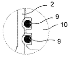
2개의 이전 솔루션들 모두는 투과성의 위험 및 오링들을 따라 누수(leakage)를 야기하고, 누수는 시간에 따라 증가하고, 도 1d 및 2d에서 보이는 바와 같이, 실들과의 접촉 구역들에서 내부 라이너 칼라 및 열가소성 재료의 삽입물의 “크립(creep)” 현상(시간 및 영구적인 스트레스의 조건에 의존하는 점차적인 플라스틱 변형)의 원인이 된다.Both of the two previous solutions cause leakage along the risk of osmosis and o-rings, the leakage increases with time, and the inner liner collar and the inner liner collar at contact zones with the chambers, as shown in Figs. 1d and 2d, &Quot; creep " phenomenon of thermoplastic material inserts (gradual plastic deformation depending on time and conditions of permanent stress).
따라서 본 발명의 목적은 비금속 라이너 라이닝 및 타입 4 압력 용기들의 금속 보스 사이의 커플링을 향상시켜 영구적인 가스 불투과성을 보장하는 것이다.It is therefore an object of the present invention to improve the coupling between the metal bosses of non-metallic liner linings and
이런 목적들 및 다른 목적들은, 가스 불투과성 라이너와 가스 불투과성 라이너의 주위의 외부에서 형성되는 복합 재료의 보강 레이어뿐만 아니라 외부 덕트와 연결될 수 있는 용기의 개구부를 형성하기 위해 불투과성 라이너 및 보강 레이어에 커플링되는 보스를 갖는 압력 용기의 수단들로 달성되고, 중합체 실링 매스(7)는 불투과성 라이너(2) 및 보스(5) 사이에 배열되고, 중합체 실링 매스(7)는 실링 매스(7)의 제자리의(in-situ) 가교 결합(cross-linking)의 수단들에 의해 불투과성 라이너(2) 및 보스(5) 모두에 묶인다.These and other objects are achieved by providing an article comprising a reinforcing layer of a composite material formed outside of a gas impermeable liner and a gas impermeable liner, as well as an impermeable liner and a reinforcing layer to form an opening in the container, The
가교 결합된 중합체 실링 매스는, 비금속 불투과성 라이너 및 금속 보스 모두에 묶인 안정적, 불투과성 및 영구적인 결합을 창작한다.The crosslinked polymer sealing mass creates a stable, impermeable and permanent bond tied to both the non-metal impermeable liner and the metal boss.
발명의 일 측면에 따르면, 가교 결합된 실링 매스는 불투과성 라이너의 가능한 변형들을 보상(compensate)하도록 적응할 수 있는 탄성 중합체이다.According to one aspect of the invention, the crosslinked sealing mass is an elastomer that is adapted to compensate for possible deformations of the impermeable liner.
또한, 보스 및 보스 내로 나사 결합하는 밸브 사이의 하나 이상의 오링들은 보스의 금속 실링 표면에 직접적으로 접촉한다.In addition, one or more O-rings between the boss and the valve threaded into the boss directly contact the metal sealing surface of the boss.
이러한 방식으로, 실(seal)에 의해 맞물리는 표면들의 미끄러짐(“크립”) 현상의 위험을 간단하고 효율적으로 제거하고 타입 1 압력 용기들(강)의 신뢰성 수준들을 달성하는 것이 가능하다.In this way, it is possible to simply and efficiently eliminate the risk of slipping (" creep ") phenomena of the surfaces engaged by the seals and to achieve the reliability levels of
본 발명 및 그것의 실시 예들의 이점들을 보다 명확한 이해를 위해, 비-제한적인 예들에 의해 만들어진 실시 예들의 일부가 도면들을 참조하여 아래에서 설명될 것이다:
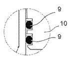
도 1a 내지 도 1d는 이전 기술의 가스 실린더 내의 불투과성 라이너 및 보스 사이의 결합의 크립 현상을 나타낸다.
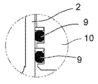
도 2a 내지 도 2d는 가스 실린더 내의 불투과성 라이너 및 보스 사이의 결합의 또 다른 결합 해결책의 크립 현상을 나타낸다.
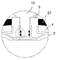
도 3은 본 발명에 따른 압력 용기의 상세한 단면도이다.
도 4는 도 3의 용기의 보스-불투과성 라이너 커플링 구역의 확대도이다.
도 5는 다른 실시 예에 따른 압력 용기의 보스-불투과성 라이너 커플링 구역의 확대도이다.
도 6은 일 실시 예에 따른 압력 용기의 보스에서 불투과성 라이너의 상세한 확대도이다.
도 7은 일 실시 예에 따른 압력 용기의 보스의 부분의 사시도이다.For a clearer understanding of the present invention and the advantages of its embodiments, some of the embodiments made by non-limiting examples will be described below with reference to the drawings:
Figs. 1a to 1d show the creep phenomenon of the bond between the impermeable liner and the boss in the gas cylinder of the prior art.
Figures 2a to 2d show the creep phenomenon of another bonding solution of bonding between the impermeable liner and the boss in the gas cylinder.
3 is a detailed sectional view of a pressure vessel according to the present invention.
Figure 4 is an enlarged view of the boss-impermeable liner coupling section of the container of Figure 3;
5 is an enlarged view of a boss-impermeable liner coupling zone of a pressure vessel according to another embodiment.
6 is a detailed enlarged view of an impermeable liner in a boss of a pressure vessel according to one embodiment.
7 is a perspective view of a portion of a boss of a pressure vessel in accordance with one embodiment.
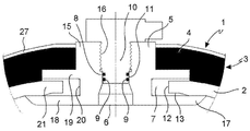
도 3 내지 도 7을 참조하면, 압력 용기(1)는 가스 불투과성 라이너(2, 일반적으로 용기(1)의 벽(3)의 가장 내부의 레이어)와, 불투과성 라이너(2)의 주위의 외부에서 형성되는 복합 재료의 보강 레이어(4)와, 압력 용기(1)의 개구부(6)를 얻기 위해 불투과성 라이너(2) 및 보강 레이어(4)에 커플링되는 적어도 하나의 보스(5)를 구비하고, 적어도 하나의 보스(5)는 외부 덕트(도시되지 않음)에 연결 가능하고, 중합체 실링 매스(7)는 불투과성 라이너(2) 및 보스(5) 사이에 배열되고, 중합체 실링 매스(7)는 실링 매스(7)의 제자리의 가교 결합의 수단들에 의해 불투과성 라이너(2) 및 보스(5) 모두에 묶인다.3 to 7, the
가교 결합된 중합체 실링 매스(7)는, 비금속 불투과성 라이너(2) 및 금속 보스(5) 모두에 묶인 안정적, 불투과성 및 영구적인 결합을 창작한다.The crosslinked
일 실시 예에서, 실링 매스(7)는 일정 한계들 내에서 불투과성 라이너(2)의 가능한 변형들에 적응하고 보상하는데 적합한 탄성 중합체(elastomer)다.In one embodiment, the sealing
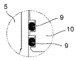
또한, 불투과성 라이너(2) 및 실링 매스(7)는 보스(5) 내부에 나사로 고정되는 밸브(10)의 하나 이상의 오링들(9) 및 보스(5) 사이의 밸브 실링 인터페이스(8)에 의해 이격되고, 밸브(10)의 하나 이상의 실링 링들(9)은 보스(5)의 금속 실링 표면(11)에 직접적으로 접촉한다.The
이러한 방식으로, 실(seal)에 의해 맞물리는 표면들의 미끄러짐(“크립”) 현상의 위험을 간단하고 효율적으로 제거하고, 타입 1 압력 용기들(강(steel))의 신뢰성 수준들을 달성하는 것이 가능하다.In this way it is possible to simply and efficiently eliminate the risk of slippage (" creep ") of surfaces engaging by a seal and to achieve reliability levels of
일 실시 예에서, 제자리의 가교 결합된 중합체 실링 매스(7)의 접착은 불투과성 라이너(2) 및 실링 매스(7) 사이의 인터페이스(12)에서의 제 1 보조 접착제(13)의 존재에 의해 더욱 향상된다. 보조 접착제(13)의 일 예는, 폴리아미드(polyamide) 불투과성 라이너(2, PA6 또는 PA66)의 예에서 아미드와 강한 화학 결합을 생성하는 레조르시놀 포름알데히드 라텍스(RFL, resorcinol formaldehyde latex)이다.In one embodiment, the adhesion of the in situ crosslinked
유사하게, 제 2 보조 접착제(14)가 실링 매스(7) 및 보스(5) 사이의 인터페이스(14)에 제공될 수 있다.Similarly, a second
일 실시 예에서, 전체 실링 매스(7)는 전구체(precursor)들을 기초로 한 레조르시놀 포름알데히드 라텍스(RFL)의 혼합물로 구성됨으로써, 제자리의 가교 결합 프로세스는 탄성 중합체(라텍스)가 금속 보스에 미리 접착하고, 안정적이고 비가역적인 방식으로 불투과성 라이너(2)와 화학 결합들을 고정하게 한다.In one embodiment, the entire sealing
일 실시 예에서, 보스(5)는 용기의 개구부(6)를 통해 가압된 유체를 위한 통로를 형성하고, 밸브(10)의 하나 이상의 실링 링(9)들이 맞닿는, 바람직하게 부드럽고 실린더형(cylinderical)이거나 부드럽고 절두원추형(frustoconical)인 상기 금속 실링 표면(11, 관 모양 부분(15)의 내부 표면)에 밸브(10)를 나사로 결합시키기 위한 나사산 시트(16, threaded seat)를 형성하는 중앙 관 모양의 부분(15)을 포함한다. 커플링 플랜지(17, coupling flange)는 예를 들어 단일 또는 이중 고리 모양의 디스크 형상으로 관 모양의 부분(15)으로부터 튀어나오고(project), 보스(5) 및 불투과성 라이너(2)의 연결을 위한 시트를 형성한다(도 3 및 도 4). 관 모양의 부분(15) 및 커플링 플랜지(17)로 구성되는 보스(5)는, 예를 들어 칩 제거 기계가공(machining), 포깅(forging), 몰딩(moulding) 또는 이들 기계가공 및 형성 작업들의 조합에 의해, 또는 후속적으로 함께 조립되는 몇 개의 초기 분리된 피스(piece, 도 5)들에 의해, 하나의 피스(도 4)로 만들어 질 수 있다.In one embodiment, the
일 실시 예에서, 커플링 플랜지(17)는 2개(반드시 원 모양일 필요는 없음)의, 바람직하게는 실질적으로 평행한 고리 모양의 디스크들(18, 19)을 형성하고, 디스크들 사이에는 보스(5)의 외측을 향하여 방사상의 방향으로 개구된 고리 모양의 슬롯 또는 그루브(20)가 형성된다. 고리 모양의 슬롯(20)은 실링 매스(7)의 인터페이스에 의해 불투과성 라이너(2)의 대응하는 프리 엣지(21) 또는 칼라를 수용한다. 그것의 최종 구성에서, 제자리의 가교 결합 후, 실링 매스(7)는 커플링 플랜지(17)의 고리 모양의 슬롯(20)에 소장된 링을 형성할 수 있고, 횡단면(보스에 관하여 방사상)에서 불투과성 라이너의 프리 엣지(21)를 포위하는 U 형상을 구비할 수 있다. 불투과성 라이너(2)의 칼라(21) 및 실링 매스(7) 모두는 커플링 플랜지의 고리 모양의 슬롯(20) 내부에 배열된다.In one embodiment, the
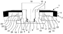
일 실시 예(도 5)에서, 커플링 플랜지(17)의 내부 고리 모양의 디스크(18)는 관 모양의 부분(15)과 하나의 피스로 형성되고, 외부 고리 모양의 디스크(19)는 2개의 디스크들(18, 19) 사이의 축 거리를 조정할 수 있도록 관 모양의 부분(15)의 외측 나사산에 나사로 결합될 수 있다. 이는 실링 매스(7)의 형성 이전에 불투과성 라이너(2) 및 보스(5)의 조립을 용이하게 하고, 다른 두께들을 갖는 불투과성 라이너들에 보스를 적용할 수 있게 한다.In one embodiment (Figure 5), the inner
내부 고리 모양의 디스크(18) 및 불투과성 라이너(2)의 프리 엣지(21)는 불투과성 라이너(2)의 개구부(6)에 보스(5)를 삽입 및, 예를 들어 90° 회전에 의해 형상-잠금(shape-locking)을 허용하기 위해 타원형 또는 일반적으로 가늘고 상보적인(complementary) 형상을 가질 수 있다(도 6 및 도 7).The inner
신뢰성 있고 반복 가능한 포지셔닝(positioning) 기준을 제공하기 위해, 커플 링 플랜지(17)의 외부 고리 모양의 디스크(19)는 적어도 하나의 포지셔닝 돌출부(22, protrusion)를 구비하고, 적어도 하나의 포지셔닝 돌출부(22)는 예를 들어 원형이고 대응하는 포지셔닝 리세스(23, recess), 예를 들어, 불투과성 라이너(2)의 외부 표면(24)에 만들어진 원형 그루브에 삽입되기에 적합한 관 모양의 부분(15)의 길이 방향 축과 동심(concentric)을 이룰 수 있다(도 5 및 도 7).To provide a reliable and repeatable positioning reference the outer
일 실시 예에서, 불투과성 라이너(2)의 칼라 또는 프리 엣지(21)는 실링 매스(7)와 접촉 영역에 하나 이상의 리세스들 또는 관통 구멍들(25)을 가지며, 이로써 리세스들 및/또는 관통 구멍들(25) 내에서의 실링 매스(7)의 관통(penetration)과, 탄성 중합체 실링 매스(7) 및 불투과성 라이너(2) 사이에 부가적인 구조적 커플링을 형성한다(도 5 및 도 6).In one embodiment, the collar or
커플링 플랜지(17)의 보스(5), 특히 외부 고리 모양의 디스크(19)는 보스(5)의 외측으로부터 실링 매스(7)에 의해 채워지도록 의도된 공간까지 연장하는 하나 이상의 주입 구멍들(26)을 형성할 수 있다. 상기 주입 구멍들(26)은 실링 매스(7)의 아직 가교 결합되지 않은 전구체의 삽입을 용이하게 하고, 실링 매스(7)의 제자리의 가교 결합 후에 부가적인 기계적 커플링을 형성한다.The
실링 매스(7)는 바람직하게는 고무, 예를 들어 실리콘 또는 라텍스 고무 또는 다른 단일 성분 전구체 또는 다성분 전구체들의 혼합물 형태로 주입 가능하거나 퍼질수 있는(spreadable) 탄성 중합체이고, 예를 들어 열 처리(가열)에 의해서 가교 결합될 수 있다.The sealing
실링 매스(7) 및 보조 접착제(13) 모두는,Both the sealing
- 적어도 하나의 레조르시놀 포름알데히드(resorcinol formaldehyde) 수지(resin) 및 클로로술폰화 폴리에틸렌(chlorosulfonated polyethylene)을 함유하는 라텍스,A latex containing at least one resorcinol formaldehyde resin and chlorosulfonated polyethylene,
- 비닐피리딘(vinylpiridine) 및/또는 수소화 아크릴로니트릴 부타디엔 고무(HNBR, hydrogenated acrylonitrile butadiene rubber)를 갖거나 갖지 않는 레조르시놀 포름알데히드 수지를 포함하는 라텍스,A latex comprising a resorcinol formaldehyde resin with or without vinyl pyridine and / or hydrogenated acrylonitrile butadiene rubber (HNBR)
- 적어도 하나의 레조르시놀 포름알데히드 비닐피리딘 수지 및 아크릴로니트릴 부타디엔 고무(NBR)를 포함하는 라텍스,A latex comprising at least one resorcinol formaldehyde vinylpyridine resin and acrylonitrile butadiene rubber (NBR)
- 적어도 하나의 레조르시놀 포름알데히드 수지 및 클로로술폰화 폴리에틸렌 수지를 포함하는 라텍스를 포함할 수 있다.- a latex comprising at least one resorcinol formaldehyde resin and a chlorosulfonated polyethylene resin.
합성(synthetic) 재료의 불투과성 라이너(2)는 예를 들어 폴리아미드(PA6 또는 PA66), 폴리에틸렌(PE), 고밀도 폴리에틸렌(HDPE), 폴리프로필렌(PP), 아크릴로니트릴 부타디엔 스티렌(ABS)이거나, 이와 유사할 수 있다.The
불투과성 라이너(2)는 이하 수단들에 의해 보강 레이어(4)에 붙을 수 있다:The
- 하나 이상의 가능한 중간 레이어들을 갖는 보강 레이어(4)로 구성된 몰드(mould) 내로의 블로우 몰딩(blow moulding) 및/또는- blow molding into a mold consisting of a reinforcing layer (4) with one or more possible intermediate layers and / or
- 불투과성 라이너(2)의 몰딩(예를 들어, 보강 레이어(4)로부터 다른 몰드를 사용하는 것) 및 불투과성 라이너(2) 주변의 보강 레이어(4)의 이어지는 포장.The subsequent packaging of the impermeable liner 2 (for example using a different mold from the reinforcement layer 4) and the
보강 레이어(4)는 저장된 유체에 의해 가해지는 내부 압력을 견디는 기능을 구비할 수 있고, 보강 레이어(4)는 이전에 제조된 불투과성 라이너 또는 레이어(2), 또는 이어서 제거되는 맨드릴(mandrel) 상에 에폭시 수지(epoxy resin)로 함침된(impregnate) 연속 탄소 섬유들의 필라멘트들을 권취(wind)에 의해 제조될 수 있다.The reinforcing
보강 레이어(4) 의 보강 섬유들은 4500MPa을 넘는, 바람직하게는 4800MPa-5200MPa의 인장력을 구비할 수 있고, 200GPa를 넘는 탄성의 모듈러스(modulus), 바람직하게는 200GPa-250GPa의 탄성의 모듈러스이다.The reinforcing fibers of the reinforcing
유리하게는 보강 레이어(4)는 보강 섬유들의 (부피)함량을 50% 내지 70%, 바람직하게는 55% 내지 65 %, 보다 바람직하게는 약 60%로 포함하고, 나머지 체적은 열처리, 예를 들어 약 5시간동안 120도 이상에서의 가열에 의해 경화되는 에폭시 수지 또는 비닐에스테르(vinylester)일 수 있는 매트릭스(matrix)로 이루어진다.Advantageously, the reinforcing
보강 레이어(4)의 주위로 더 외부 보호 레이어(27), 예를 들어 페인트 레이어 또는 내충격성(shock-proof) 레이어가 만들어진다.A further outer
보스(5)는 금속 재료, 예를 들어 강(steel)로 만들어진다. The
실링 매스(7)의 불투과성 라이너(2)에 대한 점착성(adherence)을 향상시키기 위해, 플라즈마 표면 활성화 프로세스를 사용하여 실링 매스(7)를 도포(apply)하기 전에 불투과성 라이너(2)를 처리하는 것이 적절할 수 있다.In order to improve the adherence of the sealing
이러한 목적을 위해 플라즈마, 즉 매우 낮은 표면 에너지를 가진 가볍게 분극된(polarize) 플라스틱 재료들과도 반응할 수 있는 양이온들, 음이온들 및 중성자들로 구성된 전기적으로 중성인 매체(medium) 또는 슈퍼 이온화된(super-ionised) 가스가 생성된다. 용어 “이온화된”은 원자 또는 분자에 묶이지 않은 자유 전자들의 존재를 나타낸다. 플라즈마는 가스에 고 에너지 방전을 가함으로써 생성된다. 가스는 전자들, 이온들, 고 반응성 자유 라디칼(radical)들, 단파 UV 광 포토(light photo)들 및 기타 에너지화된 입자들로 분해된다. 고 활성 플라즈마 내의 자유 라디칼들 및 다른 입자들은, 플라스틱 재료의 불투과성 라이너(2)의 표면에 결합할 수 있고, 탄성 중합체 실링 매스(7)에 대해 개선된 화학적 인력(attraction)을 갖는 부가적인 극성 그룹들이 형성된다.To this end, a plasma, an electrically neutral medium consisting of cations, anions and neutrons capable of reacting with lightly polarized plastic materials with very low surface energies, or a superionic a super-ionised gas is produced. The term " ionized " refers to the presence of free electrons that are not bound to atoms or molecules. Plasma is generated by applying a high energy discharge to the gas. The gas decomposes into electrons, ions, highly reactive free radicals, short wave UV light photos, and other energized particles. The free radicals and other particles in the highly active plasma are capable of binding to the surface of the
보스(5)의 금속 표면(7)은, 샌딩(sanding) 또는 피킹(picking) 및/또는 접착성 프라이머(primer)의 레이어의 도포에 의해 실링 매스(7)의 도포 전에 처리될 수 있다.The
불투과성 라이너(2)를 갖는 보스(5)의 기계적인 조립 후, 예를 들어 보스의 커플링 플랜지에 만들어진 주입 구멍들을 통해, 보스(5) 및 불투과성 라이너(2) 사이의 커플링 구역으로 실링 매스(7)의 전구체가 퍼지거나 주입된다.After the mechanical assembly of the
실링 매스(7)의 전구체를 주입한 후, 예를 들어 가열에 의해 가교 결합 프로세스가 실행된다. 이는, 예를 들어 전기 저항기들 또는 전기 유도를 사용하여, 보스의 금속 파트들을 가열함으로써 수행될 수 있다.After injecting the precursor of the sealing
이렇게 제조 및 구성된 압력 용기(1)는, 예를 들어, 가스 실린더 또는 압력 축전지(accumulator)로 사용될 수 있다.The
명백하게, 당업자는 하기 청구 범위들에 정의된 바와 같은 본 발명의 보호 범위 내에서 조건부 및 특정 요구사항들을 만족시키기 위해 본 발명에 따른 압력 용기 및 제조 방법을 추가로 변형 및 다양화시킬 수 있다.Obviously, those skilled in the art will be able to further modify and diversify the pressure vessel and method of manufacture according to the present invention to meet conditional and specific requirements within the scope of protection of the present invention as defined in the following claims.
Claims (16)
상기 압력 용기(1)는, 가스 불투과성 라이너(2)와 상기 불투과성 라이너(2) 주위의 외부에서 형성되는 복합 재료의 보강 레이어(4)를 갖고, 상기 압력 용기(1)의 개구부(6)를 얻기 위해 상기 불투과성 라이너(2) 및 상기 보강 레이어(4)에 커플링되는 적어도 하나의 보스(5)를 구비하고,
중합체 실링 매스(7)는 상기 불투과성 라이너(2) 및 상기 보스(5) 사이에 배열되고, 상기 중합체 실링 매스(7)는 상기 실링 매스(7)의 제자리의 가교 결합에 의해서 상기 불투과성 라이너(2) 및 상기 보스(5)에 묶이는 압력 용기(1).
In the pressure vessel 1,
The pressure vessel 1 has a gas impervious liner 2 and a reinforcement layer 4 of a composite material formed outside the impermeable liner 2 at the periphery thereof. At least one boss (5) coupled to the impermeable liner (2) and to the reinforcing layer (4)
A polymeric sealing mass (7) is arranged between said impermeable liner (2) and said boss (5), said polymeric sealing mass (7) being formed by in situ crosslinking of said sealing mass (7) (2) and the boss (5).
상기 불투과성 라이너(2)는 비금속이고, 상기 보스(5)는 금속이고, 상기 실링 매스(7)는 탄성 중합체의 고무인 압력 용기(1).
The method according to claim 1,
Wherein the impermeable liner (2) is a base metal, the boss (5) is a metal, and the sealing mass (7) is an elastomeric rubber.
상기 불투과성 라이너(2) 및 상기 실링 매스(7)는, 상기 보스(5)에 나사로 고정되는 밸브(10)의 적어도 하나의 오링 개스킷(9) 및 상기 보스(5) 사이의 밸브 실링 인터페이스(8)에 의해 이격되고, 상기 오링 개스킷(9)은 상기 보스(5)의 금속 실링 표면(11)에 직접적으로 접촉하는 압력 용기(1).
3. The method according to claim 1 or 2,
Characterized in that the opaque liner (2) and the sealing mass (7) comprise at least one o-ring gasket (9) of a valve (10) screwed onto the boss (5) 8), said o-ring gasket (9) being in direct contact with the metal sealing surface (11) of said boss (5).
상기 불투과성 라이너(2) 및 상기 실링 매스(7) 사이의 인터페이스(12)에서의 제 1 보조 접착제(13)를 포함하는 압력 용기(1).
4. The method according to any one of claims 1 to 3,
And a first auxiliary adhesive (13) at the interface (12) between the impermeable liner (2) and the sealing mass (7).
상기 실링 매스(7) 및 상기 보스(5) 사이의 인터페이스(14)에서의 제 2 보조 접착제(14)를 포함하는 압력 용기(1).
5. The method according to any one of claims 1 to 4,
And a second secondary adhesive (14) at the interface (14) between the sealing mass (7) and the boss (5).
- 상기 보스(5)는 밸브(10)를 나사로 고정하기 위한 나사산 시트(16)를 갖는 관 모양의 중앙 부분(15)과, 상기 관 모양의 부분(15)으로부터 튀어나오고 2개의 고리 모양의 디스크들(18, 19)를 형성하는 커플링 플랜지(17)를 포함하고, 상기 2개의 고리 모양의 디스크들(18, 19)은 상기 보스(5)의 길이 방향의 축에 대하여 방사상으로 바깥쪽으로 개구되는 고리 모양의 슬롯(20)을 상기 2개의 고리 모양의 디스크들(18, 19) 사이에 규정하고,
- 상기 고리 모양의 슬롯(20)은 상기 실링 매스(7)의 개재에 의해 상기 불투과성 라이너(2)의 대응하는 프리 엣지(21)를 수용하고,
- 상기 실링 매스(7)는, 상기 고리 모양의 슬롯(20) 내에 수용되고 상기 불투과성 라이너(2)의 상기 프리 엣지(21)를 에워싸는 U형상의 단면을 구비하는 링을 형성하고,
- 상기 불투과성 라이너(2)의 상기 프리 엣지(21) 및 상기 실링 매스(7)는 상기 고리 모양의 슬롯(20) 내부에 배열되는 압력 용기(1).
6. The method according to any one of claims 1 to 5,
The boss 5 comprises a tubular central portion 15 having a threaded seat 16 for screwing the valve 10 and a central annular portion 15 projecting from the tubular portion 15 and having two annular discs 15, Wherein the two annular discs (18, 19) are radially outwardly open with respect to the longitudinal axis of the boss (5), and a coupling flange (17) Shaped slot 20 between the two annular discs 18, 19,
- said annular slot (20) receives the corresponding free edge (21) of said impermeable liner (2) by interposition of said sealing mass (7)
Said sealing mass (7) forming a ring having a U-shaped cross-section which is received in said annular slot (20) and which surrounds said free edge (21) of said impermeable liner (2)
- the pressure vessel (1) in which the free edge (21) and the sealing mass (7) of the impermeable liner (2) are arranged inside the annular slot (20).
상기 커플링 플랜지(17)의 내부 고리 모양의 디스크(18)는 상기 관 모양의 부분(15)과 함께 단일 피스로 형성되고, 외부 고리 모양의 디스크(19)는 상기 2개의 고리 모양의 디스크들(18, 19) 사이의 축 거리를 조정할 수 있도록 상기 관 모양의 부분(15)의 외부 나사산에 나사로 고정될 수 있는 압력 용기(1).
The method according to claim 6,
An inner annular disk 18 of the coupling flange 17 is formed as a single piece with the tubular portion 15 and an outer annular disk 19 is formed as a single piece, Can be screwed to the external threads of the tubular part (15) so as to adjust the shaft distance between the tubular part (18, 19).
상기 내부 고리 모양의 디스크(18) 및 상기 불투과성 라이너(2)의 상기 개구부(6)의 상기 프리 엣지(21)는 타원 또는 일반적으로 가늘고 상보적인 형상을 가져서, 상기 불투과성 라이너(2)의 상기 개구부(6) 내로 상기 보스(5)의 삽입과 상기 불투과성 라이너(2)에 대하여 상기 보스의 회전의 차단을 허용하는 압력 용기(1).
8. The method of claim 7,
The inner annular disc 18 and the free edge 21 of the opening 6 of the impermeable liner 2 have an elliptical or generally generally slender and complementary shape so that the opaque liner 2 (1) allowing insertion of said boss (5) into said opening (6) and interruption of rotation of said boss relative to said impermeable liner (2).
상기 커플링 플랜지(17)의 상기 외부 고리 모양의 디스크(19)는, 바람직하게는 원형이고 상기 관 모양의 부분(15)의 길이 방향의 축과 동심인 적어도 하나의 포지셔닝 돌출부(22)를 형성하고, 상기 포지셔닝 돌출부(22)는 상기 불투과성 라이너(2)의 외부 표면(24)에 형성된 대응하는 포지셔닝 리세스(23), 바람직하게는 원형 그루브에 삽입되는 압력 용기.
8. The method of claim 7,
The outer annular disc 19 of the coupling flange 17 is preferably circular and forms at least one positioning projection 22 concentric with the longitudinal axis of the tubular portion 15 And said positioning protrusion (22) is inserted into a corresponding positioning recess (23), preferably a circular groove, formed in the outer surface (24) of said impermeable liner (2).
상기 불투과성 라이너(2)는 상기 실링 매스(7)와의 접촉 구역에 하나 이상의 관통 구멍들(25)을 구비하고, 상기 관통 구멍들(25) 내로 연장하는 상기 실링 매스(7)의 섹션들은 상기 실링 매스(7) 및 상기 불투과성 라이너(2) 사이에 부가적인 구조적 커플링을 만드는 압력 용기(1).
10. The method according to any one of claims 1 to 9,
The impermeable liner 2 has one or more through holes 25 in the area of contact with the sealing mass 7 and the sections of the sealing mass 7 extending into the through holes 25, A pressure vessel (1) that creates additional structural coupling between the sealing mass (7) and the impermeable liner (2).
상기 보스(5)는 상기 보스(5)의 외측으로부터 상기 실링 매스(7)에 의해 차지되는 공간까지 연장하는 하나 이상의 주입 구멍들(26)을 형성하는 압력 용기(1).
11. The method according to any one of claims 1 to 10,
Wherein the boss (5) forms one or more injection holes (26) extending from the outside of the boss (5) to the space occupied by the sealing mass (7).
A) 상기 실링 매스(7)는 고무, 실리콘 고무, 라텍스, 탄성 중합체로 구성되는 군으로부터 선택되고, 단일성분 전구체 또는 다성분 전구체들의 혼합물 형태로 주입 가능하거나 퍼질 수 있고, 열처리에 의해 가교 결합될 수 있고,
B) 상기 불투과성 라이너(2)는 폴리아미드, 폴리에틸렌, 고밀도 폴리에틸렌, 폴리프로필렌, 아크릴로니트릴 부타디엔 스티렌으로 구성되는 군으로부터 선택된 합성 물질로 만들어지고,
- 상기 보강 레이어(4)는 에폭시 수지가 함침된, 연속적인 탄소 또는 유리 섬유들의 필라멘트의 포장을 포함하고,
- 상기 보스(5)는 강으로 만들어지는 압력 용기(1).
12. The method according to any one of claims 1 to 11,
A) The sealing mass 7 is selected from the group consisting of rubber, silicone rubber, latex, elastomer and can be injected or dispersed in the form of a mixture of single component precursors or multicomponent precursors and crosslinked by heat treatment Can,
B) The impermeable liner (2) is made of a synthetic material selected from the group consisting of polyamide, polyethylene, high density polyethylene, polypropylene, acrylonitrile butadiene styrene,
- the reinforcing layer (4) comprises a package of filaments of continuous carbon or glass fibers impregnated with an epoxy resin,
- the pressure vessel (1) in which the boss (5) is made of steel.
상기 실링 매스(7) 또는 상기 보조 접착제(13)는,
- 적어도 하나의 레조르시놀 포름알데히드 수지 및 클로로술폰화 폴리에틸렌을 함유하는 라텍스,
- 비닐피리딘 및/또는 수소화 아크릴로니트릴 부타디엔 고무(HNBR)를 갖거나 갖지 않는 레조르시놀 포름알데히드 수지를 포함하는 라텍스,
- 적어도 하나의 레조르시놀 포름알데히드 비닐피리딘 수지 및 아크릴로니트릴 부타디엔 고무(NBR)를 포함하는 라텍스,
- 적어도 하나의 레조르시놀 포름알데히드 수지 및 클로로술폰화 폴리에틸렌 수지를 포함하는 라텍스,
로 구성된 군으로부터 선택되는 압력 용기(1).
13. The method according to any one of claims 1 to 12,
The sealing mass (7) or the auxiliary adhesive (13)
A latex containing at least one resorcinol formaldehyde resin and chlorosulfonated polyethylene,
A latex comprising a resorcinol formaldehyde resin with or without vinyl pyridine and / or hydrogenated acrylonitrile butadiene rubber (HNBR)
A latex comprising at least one resorcinol formaldehyde vinylpyridine resin and acrylonitrile butadiene rubber (NBR)
A latex comprising at least one resorcinol formaldehyde resin and a chlorosulfonated polyethylene resin,
(1). ≪ / RTI >
- 상기 불투과성 라이너(2)를 제조하고 상기 보스(5)를 제조하는 단계,
- 상기 불투과성 라이너(2)와 함께 상기 보스(5)를 조립하고, 상기 보스(5) 및 상기 불투과성 라이너(2) 사이의 커플링 영역에 중공 공간을 배열하는 단계,
- 제공된 중공 공간 내에 실링 매스(7)의 전구체를 퍼지게 하거나 주입하는 단계, 및
- 이어서, 상기 실링 매스를 상기 보스(5) 및 불투과성 라이너(2) 모두에 묶기 위해 상기 실링 매스(7)의 전구체가 가교 결합 프로세스를 겪게 하는 단계,
를 포함하는 압력 용기(1)를 제조하는 방법.
14. The method according to any one of claims 1 to 13,
- fabricating said impermeable liner (2) and producing said boss (5)
- assembling said boss (5) with said impermeable liner (2), arranging a hollow space in a coupling region between said boss (5) and said impermeable liner (2)
- spreading or injecting the precursor of the sealing mass (7) into the provided hollow space, and
- causing the precursor of the sealing mass (7) to undergo a crosslinking process to bind the sealing mass to both the boss (5) and the impermeable liner (2)
(1). ≪ / RTI >
상기 가교 결합 프로세스는 상기 보스(5)의 금속 파트들을 가열하는 단계를 포함하는 압력 용기를 제조하는 방법.
15. The method of claim 14,
Wherein the cross-linking process comprises heating the metal parts of the boss (5).
플라즈마 표면 활성화 프로세스에 의해 상기 실링 매스(7)를 도포하기 전에 상기 불투과성 라이너(2)를 처리하는 단계를 포함하는 압력 용기를 제조하는 방법.16. The method according to claim 14 or 15,
Treating the impermeable liner (2) prior to applying the sealing mass (7) by a plasma surface activation process.
Applications Claiming Priority (3)
| Application Number | Priority Date | Filing Date | Title |
|---|---|---|---|
| ITMI20141311 | 2014-07-17 | ||
| ITMI2014A001311 | 2014-07-17 | ||
| PCT/IB2015/054540 WO2016009288A1 (en) | 2014-07-17 | 2015-06-16 | Pressure vessel |
Publications (1)
| Publication Number | Publication Date |
|---|---|
| KR20170032388A true KR20170032388A (en) | 2017-03-22 |
Family
ID=51628347
Family Applications (1)
| Application Number | Title | Priority Date | Filing Date |
|---|---|---|---|
| KR1020177004019A KR20170032388A (en) | 2014-07-17 | 2015-06-16 | Pressure vessel |
Country Status (7)
| Country | Link |
|---|---|
| US (1) | US10240720B2 (en) |
| EP (1) | EP3169929A1 (en) |
| JP (1) | JP2017528666A (en) |
| KR (1) | KR20170032388A (en) |
| AR (1) | AR103109A1 (en) |
| MX (1) | MX2017000709A (en) |
| WO (1) | WO2016009288A1 (en) |
Families Citing this family (6)
| Publication number | Priority date | Publication date | Assignee | Title |
|---|---|---|---|---|
| US10379073B2 (en) * | 2014-03-28 | 2019-08-13 | Faber Industrie S.P.A. | Composite-material pressure vessel and system and method for controlling the vessel |
| ITUA20164707A1 (en) * | 2016-06-28 | 2017-12-28 | Faber Ind Spa | PRESSURE CONTAINER |
| US10753474B2 (en) * | 2017-11-07 | 2020-08-25 | Hexagon Technology As | Blind boss fitting with redundant seal |
| CN109751506A (en) * | 2019-02-28 | 2019-05-14 | 上海华敬氢能科技有限公司 | A kind of plastic inner container carbon fiber winds hydrogen storage cylinder entirely |
| FR3116880B1 (en) * | 2020-11-30 | 2023-06-23 | Faurecia Systemes Dechappement | Pressurized gas storage tank including an anti-shock system |
| KR102460148B1 (en) * | 2021-01-04 | 2022-11-01 | 주식회사 성우하이텍 | pressure vessel |
Family Cites Families (16)
| Publication number | Priority date | Publication date | Assignee | Title |
|---|---|---|---|---|
| US3843010A (en) * | 1971-10-13 | 1974-10-22 | Brunswick Corp | Metal lined pressure vessel |
| CH670419A5 (en) * | 1986-08-11 | 1989-06-15 | Ciba Geigy Ag | |
| US5429845A (en) * | 1992-01-10 | 1995-07-04 | Brunswick Corporation | Boss for a filament wound pressure vessel |
| DE69206114T2 (en) * | 1992-01-10 | 1996-04-18 | Technical Products Group Inc | Pole piece for a fiber-wound pressure vessel. |
| JPH10231998A (en) * | 1997-02-24 | 1998-09-02 | Toyoda Gosei Co Ltd | Pressure vessel and its manufacture |
| JPH1182887A (en) * | 1997-09-08 | 1999-03-26 | Toyoda Gosei Co Ltd | Pressure vessel |
| JP3523802B2 (en) * | 1999-04-07 | 2004-04-26 | 豊田合成株式会社 | Pressure vessel |
| US20030111473A1 (en) * | 2001-10-12 | 2003-06-19 | Polymer & Steel Technologies Holding Company, L.L.C. | Composite pressure vessel assembly and method |
| JP4193492B2 (en) * | 2002-12-27 | 2008-12-10 | 豊田合成株式会社 | Pressure vessel |
| JP4935117B2 (en) * | 2005-11-08 | 2012-05-23 | トヨタ自動車株式会社 | tank |
| JP2009293742A (en) * | 2008-06-06 | 2009-12-17 | Toyota Motor Corp | Tank |
| WO2011152732A1 (en) * | 2010-05-31 | 2011-12-08 | Ragasco As | Inlet/outlet system for composite pressure container |
| JP5955497B2 (en) * | 2010-08-31 | 2016-07-20 | 横浜ゴム株式会社 | Rubber composition for bonding brass plating wire and hydraulic hose |
| DE102011120041A1 (en) * | 2011-12-02 | 2013-06-06 | Volkswagen Aktiengesellschaft | Pressure tank for motor vehicle, for storing fluid medium, has sealing portion that is formed between wall section of base surface and mounting flange portions connected with connecting terminal structure to form one-piece portion |
| JP5807535B2 (en) * | 2011-12-14 | 2015-11-10 | セントラル硝子株式会社 | Glass fiber sizing agent and glass fiber coated with the same |
| WO2014014049A1 (en) * | 2012-07-18 | 2014-01-23 | 三菱レイヨン株式会社 | Pressure vessel |
-
2015
- 2015-06-16 WO PCT/IB2015/054540 patent/WO2016009288A1/en active Application Filing
- 2015-06-16 EP EP15736633.7A patent/EP3169929A1/en not_active Withdrawn
- 2015-06-16 JP JP2017522745A patent/JP2017528666A/en active Pending
- 2015-06-16 KR KR1020177004019A patent/KR20170032388A/en unknown
- 2015-06-16 MX MX2017000709A patent/MX2017000709A/en unknown
- 2015-06-16 US US15/326,110 patent/US10240720B2/en not_active Expired - Fee Related
- 2015-07-03 AR ARP150102150A patent/AR103109A1/en unknown
Also Published As
| Publication number | Publication date |
|---|---|
| EP3169929A1 (en) | 2017-05-24 |
| WO2016009288A1 (en) | 2016-01-21 |
| JP2017528666A (en) | 2017-09-28 |
| US20170211747A1 (en) | 2017-07-27 |
| US10240720B2 (en) | 2019-03-26 |
| AR103109A1 (en) | 2017-04-19 |
| MX2017000709A (en) | 2017-10-16 |
Similar Documents
| Publication | Publication Date | Title |
|---|---|---|
| KR20170032388A (en) | Pressure vessel | |
| JP6409887B2 (en) | Pressure vessel | |
| RU2749888C2 (en) | Pressure receiver | |
| CA2559452C (en) | The high gas-tighten metallic nozzle-boss for the high pressure composite vessel | |
| US10400956B2 (en) | Boss seal for composite overwrapped pressure vessel | |
| CN102537653B (en) | Gas storage tank comprising a liquid sealant | |
| US20130152371A1 (en) | Clamped liner-boss connection | |
| EP2787254B1 (en) | Internal pressure vessel for seawater dessalination | |
| CA3018551A1 (en) | Boss and liner interface for a pressure vessel | |
| US20160257403A1 (en) | Aircraft Water Tank | |
| US20180238491A1 (en) | Hydrogen tank body and method of producing the same, and hydrogen tank and method of producing the same | |
| MX2020013095A (en) | High-pressure tank, method for manufacturing high-pressure tank, and method for manufacturing fiber-reinforced resin layer for high-pressure tank. | |
| KR20170130650A (en) | Pressure vessel having degassing structure | |
| KR20110123429A (en) | Double nozzle-boss for the plastic liner of high pressure vessel | |
| KR102381103B1 (en) | Inner enclosure for pressurized fluid storage tanks for automobiles | |
| CN112833324A (en) | Pressure vessel | |
| KR102188243B1 (en) | Device and method for molding composite materials using VARTM | |
| KR102108437B1 (en) | Valve lining devices and lining valves | |
| JP2023160000A (en) | High-pressure tank | |
| CN110249170B (en) | High pressure seal | |
| BR102015017549A8 (en) | HIGH RESISTANCE PRESSURE CYLINDER FOR STORING GAS FLUIDS, AND PROCESS FOR PRODUCTION OF A PRESSURE CYLINDER | |
| KR20210145157A (en) | How to prevent breakage of corrugated pipe of type IV pressure vessel | |
| CN115723317A (en) | High-pressure tank with plastic-coated projections |