KR20170031033A - Methods, systems and apparatus for over-exposure correction - Google Patents
Methods, systems and apparatus for over-exposure correction Download PDFInfo
- Publication number
- KR20170031033A KR20170031033A KR1020160111738A KR20160111738A KR20170031033A KR 20170031033 A KR20170031033 A KR 20170031033A KR 1020160111738 A KR1020160111738 A KR 1020160111738A KR 20160111738 A KR20160111738 A KR 20160111738A KR 20170031033 A KR20170031033 A KR 20170031033A
- Authority
- KR
- South Korea
- Prior art keywords
- pixels
- luminance
- rti
- pixel
- block
- Prior art date
Links
- 238000000034 method Methods 0.000 title claims abstract description 73
- 238000012937 correction Methods 0.000 title description 16
- 238000012545 processing Methods 0.000 claims abstract description 21
- 239000013598 vector Substances 0.000 claims description 46
- 238000005457 optimization Methods 0.000 claims description 8
- 230000001788 irregular Effects 0.000 claims 1
- 238000003672 processing method Methods 0.000 claims 1
- 238000007670 refining Methods 0.000 claims 1
- 230000015654 memory Effects 0.000 description 26
- 238000003860 storage Methods 0.000 description 14
- 230000008569 process Effects 0.000 description 13
- 238000004891 communication Methods 0.000 description 10
- 230000006870 function Effects 0.000 description 10
- 238000010586 diagram Methods 0.000 description 6
- 238000012512 characterization method Methods 0.000 description 5
- 230000003287 optical effect Effects 0.000 description 5
- 238000009792 diffusion process Methods 0.000 description 4
- 238000013507 mapping Methods 0.000 description 4
- 230000000007 visual effect Effects 0.000 description 4
- 229920001690 polydopamine Polymers 0.000 description 3
- 238000012360 testing method Methods 0.000 description 3
- 238000012546 transfer Methods 0.000 description 3
- 239000004020 conductor Substances 0.000 description 2
- 238000005259 measurement Methods 0.000 description 2
- 238000009877 rendering Methods 0.000 description 2
- 238000007493 shaping process Methods 0.000 description 2
- 230000007704 transition Effects 0.000 description 2
- 208000004547 Hallucinations Diseases 0.000 description 1
- 239000000654 additive Substances 0.000 description 1
- 230000000996 additive effect Effects 0.000 description 1
- 238000013459 approach Methods 0.000 description 1
- 230000002457 bidirectional effect Effects 0.000 description 1
- 230000005540 biological transmission Effects 0.000 description 1
- 230000015572 biosynthetic process Effects 0.000 description 1
- 230000000295 complement effect Effects 0.000 description 1
- 230000003247 decreasing effect Effects 0.000 description 1
- 230000007547 defect Effects 0.000 description 1
- 230000000694 effects Effects 0.000 description 1
- 238000005562 fading Methods 0.000 description 1
- 238000009499 grossing Methods 0.000 description 1
- 238000003384 imaging method Methods 0.000 description 1
- 238000012886 linear function Methods 0.000 description 1
- 238000004519 manufacturing process Methods 0.000 description 1
- 239000002184 metal Substances 0.000 description 1
- 229910044991 metal oxide Inorganic materials 0.000 description 1
- 150000004706 metal oxides Chemical class 0.000 description 1
- 238000002156 mixing Methods 0.000 description 1
- 238000012986 modification Methods 0.000 description 1
- 230000004048 modification Effects 0.000 description 1
- 238000010606 normalization Methods 0.000 description 1
- 238000003909 pattern recognition Methods 0.000 description 1
- 238000007781 pre-processing Methods 0.000 description 1
- 230000003362 replicative effect Effects 0.000 description 1
- 238000012552 review Methods 0.000 description 1
- 238000005070 sampling Methods 0.000 description 1
- 239000004065 semiconductor Substances 0.000 description 1
- 238000001228 spectrum Methods 0.000 description 1
- 230000003068 static effect Effects 0.000 description 1
- 238000003786 synthesis reaction Methods 0.000 description 1
Images


Classifications
-
- G06T5/90—
-
- G06T5/94—
-
- G06T5/77—
-
- G—PHYSICS
- G06—COMPUTING; CALCULATING OR COUNTING
- G06T—IMAGE DATA PROCESSING OR GENERATION, IN GENERAL
- G06T5/00—Image enhancement or restoration
- G06T5/007—Dynamic range modification
-
- G—PHYSICS
- G06—COMPUTING; CALCULATING OR COUNTING
- G06T—IMAGE DATA PROCESSING OR GENERATION, IN GENERAL
- G06T7/00—Image analysis
- G06T7/10—Segmentation; Edge detection
- G06T7/13—Edge detection
-
- G—PHYSICS
- G06—COMPUTING; CALCULATING OR COUNTING
- G06T—IMAGE DATA PROCESSING OR GENERATION, IN GENERAL
- G06T7/00—Image analysis
- G06T7/90—Determination of colour characteristics
-
- H—ELECTRICITY
- H04—ELECTRIC COMMUNICATION TECHNIQUE
- H04N—PICTORIAL COMMUNICATION, e.g. TELEVISION
- H04N23/00—Cameras or camera modules comprising electronic image sensors; Control thereof
- H04N23/70—Circuitry for compensating brightness variation in the scene
- H04N23/741—Circuitry for compensating brightness variation in the scene by increasing the dynamic range of the image compared to the dynamic range of the electronic image sensors
-
- H04N5/2355—
-
- G—PHYSICS
- G06—COMPUTING; CALCULATING OR COUNTING
- G06T—IMAGE DATA PROCESSING OR GENERATION, IN GENERAL
- G06T2207/00—Indexing scheme for image analysis or image enhancement
- G06T2207/20—Special algorithmic details
- G06T2207/20172—Image enhancement details
- G06T2207/20208—High dynamic range [HDR] image processing
Landscapes
- Engineering & Computer Science (AREA)
- Physics & Mathematics (AREA)
- General Physics & Mathematics (AREA)
- Theoretical Computer Science (AREA)
- Computer Vision & Pattern Recognition (AREA)
- Multimedia (AREA)
- Signal Processing (AREA)
- Image Processing (AREA)
- Image Analysis (AREA)
- Studio Devices (AREA)
Abstract
Description
본 개시내용은 이미지 프로세싱 및 이미지 복원에 관한 것이다. 특히, 본 개시내용은 과노출된 또는 클리핑된 스페큘러 이미지 영역(들)의 정정에 관한 것이다.This disclosure relates to image processing and image reconstruction. In particular, this disclosure relates to the correction of overexposed or clipped specular image region (s).
카메라들은 통상적으로 실제 장면들보다 더 작은 동적 범위를 가진다. 카메라의 동적 범위를 초과하는 밝은 이미지 부분들은 과노출된 또는 클리핑된 영역들로서 나타날 것이다. 카메라는 이러한 과노출된 또는 클리핑된 영역들에 컬러 채널의 최대 가능한 값을 할당할 것이다. 그러나, 이러한 최대 값의 할당은 이러한 영역들에서의 컬러, 텍스쳐, 콘트라스트 및 휘도 정보의 손실을 초래한다.Cameras typically have a smaller dynamic range than real scenes. Bright image portions that exceed the dynamic range of the camera will appear as overexposed or clipped regions. The camera will assign the maximum possible value of the color channel to these and exposed or clipped regions. However, this maximum value allocation results in loss of color, texture, contrast and luminance information in these areas.
자동차 또는 금속 물체들과 같은 스페큘러 또는 광택 물체들은 카메라 센서를 이용하여 이미징될 때 과노출된 또는 클리핑된 이미지 영역들을 초래하는 경향이 있는 스페큘러 표면들을 가진다. 스페큘러 표면들은 스페큘러 형상을 전달하기 위해 정확하게(또는 적어도 실제같이) 재생될 필요가 있는 하이라이트들을 가지는 경향이 있다.Specular or glossy objects, such as automotive or metal objects, have specular surfaces that are imaged when using a camera sensor and tend to result in exposed or clipped image areas. Specular surfaces tend to have highlights that need to be reproduced precisely (or at least practically) to deliver a specular shape.
인페인팅(inpainting)은, 과노출된 또는 클리핑된 영역들의 정보와 같은, 유실 이미지 정보의 이미지 영역들을 재구성하는 프로세스이다. 인페인팅은 통상적으로, 유실 정보 영역 주변의 정보를 분석하고, 유사한 주변 영역들로부터 유실 정보 영역으로 정보를 전달하거나 복제한다. 그러나, 이는, 재구성될 영역이 그것의 주변과 유사하지 않을 때 성공적이지 않다. 특히, 이는, 스페큘러 하이라이트 영역들이 이들의 주변과 상이한 특징들을 가지기 때문에, 이러한 영역들에 대해 성공적이지 않다.Inpainting is a process of reconstructing image areas of lost image information, such as information of overexposed or clipped regions. Inpainting typically analyzes information around the loss information area and transfers or replicates information from similar surrounding areas to the loss information area. However, this is not successful when the area to be reconstructed is not similar to its surroundings. In particular, this is unsuccessful for these areas because the specular highlight areas have features that are different from their surroundings.
스페큘러 하이라이트 영역들은 이웃 이미지 영역들에서 양호하게 표현되지 않는 피크 휘도 프로파일을 가진다. 그러나, 과노출 이미지 영역들의 휘도 값들은 나머지 이미지의 휘도 값들을 초과하며, 따라서, 이미지 내의 다른 곳으로부터 정보를 전달하고 복제하는 것이 적용가능하지 않다.The specular highlight areas have a peak luminance profile that is not well represented in neighboring image areas. However, the luminance values of the overexposed image areas exceed the luminance values of the remaining image, and therefore, it is not applicable to transfer and duplicate information from elsewhere in the image.
과노출 영역들의 존재는 종래의 디스플레이들 상에서 저하된 시각적 외양을 가져온다. 그러나, 이러한 문제점은 과노출 콘텐츠를 가지는 화상(imagery)이 높은 동적 범위(high dynamic range)(HDR) 디스플레이 상에서의 디스플레이를 위해 준비될 때 악화된다. 표준 동적 범위(standard dynamic range)(SDR) 콘텐츠는 일반적으로 반전 톤 재생 오퍼레이터(또한, 반전 톤 매핑 오퍼레이터 또는 짧게 iTMO로서 공지됨)의 보조로 HDR 디바이스 상에서의 디스플레이를 위해 준비될 수 있다. iTMO는 동적 범위를 비선형으로 확장시키며, 밝은 이미지 영역들이 특히 가장 큰 확장을 수용한다. 그 결과, 특징없는(featureless) 과노출 영역들이 강조될 수 있고, 시각적으로 훨씬 덜 매력적이게 될 수 있다.And the presence of exposed areas results in a degraded visual appearance on conventional displays. However, this problem is exacerbated when imagery having overexposed content is prepared for display on a high dynamic range (HDR) display. Standard SDR content can be prepared for display on HDR devices with the aid of an inverted tone reproduction operator (also known as an inverted tone mapping operator or briefly iTMO). iTMO extends the dynamic range nonlinearly, with bright image areas particularly accommodating the largest expansion. As a result, featureless and exposed areas can be emphasized and become visually much less attractive.
Pouli 등은 'Image Statistics in Visual Computing'(A K Peters / CRC Press, 2013)에서 자연 이미지들에서 발견되는 통계적 규칙성들의 개요를 제공하고, 많은 RGB-유사 컬러 공간들이 자연 이미지들에 대한 컬러 채널들 사이에서 강한 상관들을 보임을 보고한다. 이러한 특징은 하나 또는 두 개의 클리핑된 채널들을 가지는 영역들의 재구성을 위해 조정될 수 있다. 예를 들어, Abebe 등은 'Color Clipping and Over-exposure Correction'(Eurographics Symposium on Rendering (Experimental Ideas & Implementations track), 2015)에서, 컬러 이미지들의 RGB 채널들 사이의 상관에 의존하여 하나의 그리고 두 개의 채널들이 클리핑되는 영역들을 복원하는, 정정 방법을 기술한다. 밝기 재성형 방법은 모든 3개 채널들이 클리핑될 때 사용된다. Abebe 등은 'Correction of Over-Exposure using Color Channel Correlations'(IEEE GlobalSIP, 2014)에서, 교차-채널 상관들을 조정하여 클리핑된 영역들을 재구성하는 추가적인 방법을 기술한다.Pouli et al. Provide an overview of the statistical regularities found in natural images in 'Image Statistics in Visual Computing' (AK Peters / CRC Press, 2013), and note that many RGB- In the United States. This feature can be adjusted for reconstruction of regions with one or two clipped channels. For example, Abebe et al., In " Color Clipping and Over-exposure Correction ", Eurographics Symposium on Rendering (Experimental Ideas & Implementations track) Desc /
Rempel 등은, Ldr2hdr: on-the-fly reverse tone mapping of legacy video and photographs(ACM Transactions on Graphics (TOG)(2007년 8월, Vol. 26, No.3, p.39))에서, 과노출 영역들을 지시하는 마스크에 가우시안 컨볼루션(Gaussian convolution)을 적용함으로써 과노출 영역들의 재구성을 포함하는 반전 톤 매핑 기법을 기술한다. 컨볼빙된 마스크는 동일한 입력 마스크에 적용되는 에지-스톱 함수로 곱해지고, 결과적인 프로파일은 반전 톤 매핑된 이미지에 더해진다.Rempel et al., In Ldr2hdr: on-the-fly reverse tone mapping of legacy video and photographs (ACM Transactions on Graphics (TOG) (August 2007, Vol. 26, No.3, Desc /
정보가, 즉, 과노출 영역들에, 존재하지 않는 경우, 일부 기법들은 단순한 가우시안 휘도 프로파일을 중첩시켜서 이러한 영역들에 형상을 제공하는 것을 제안한다. 예를 들어, Wang 등은, High dynamic range image hallucination(높은 동적 범위 이미지 환영)(Proceedings of the 18th Eurographics conference on Rendering Techniques, 2007년 6월 (pp. 321-326))에서, 저주파수 휘도 표현을 생성하기 위해 양방향 필터를 이용한 이미지 휘도의 프로세싱을 논의한다. 고주파수 표현은 이미지와 저주파수 버전 사이의 레지듀얼(residual)에 기초하여 획득된다. 원대칭 가우시안 프로파일이 중첩되어 각각의 클리핑된 영역에 대한 새로운 휘도 프로파일들을 생성한다. Wang은 하나 이상의 스트로크(stroke)들을 이용하여 이미지를 마킹함으로써 사용자가 텍스쳐 기준을 선택할 것을 요구한다. 텍스쳐는 텍스쳐 합성 프로세스를 통해 클리핑된 영역 내에 전달된다. 새로운 휘도 프로파일, 텍스쳐 및 원래 이미지가 포아송 편집(Poisson editing)을 통해 블렌딩되어 트랜지션들을 스무스하게 한다(smooth).If information is not present, i. E., In overexposed areas, some techniques suggest superimposing a simple Gaussian luminance profile to provide a shape to these areas. For example, Wang et al. Have generated low frequency luminance representations in High dynamic range image hallucination (Proceedings of the 18th Eurographics conference on Rendering Techniques, June 2007 (pp. 321-326)). We discuss the processing of image brightness using a bidirectional filter. The high frequency representation is obtained based on the residual between the image and the low frequency version. The original symmetric Gaussian profiles are superimposed to create new luminance profiles for each clipped region. Wang requires the user to select a texture reference by marking the image using one or more strokes. The texture is delivered in the clipped region through the texture synthesis process. The new luminance profile, texture, and original image are blended through Poisson editing to smooth the transitions.
Guo 등은 Correcting over-exposure in photographs(Computer Vision and Pattern Recognition (CVPR), 2010 IEEE Conference, 2010년 6월, (pp. 515-521))에서, 각각의 픽셀의 과노출 우도비를 고려하는 최적화 프로세스를 통해 휘도 프로파일을 재생성한다.Guo et al., In Optimization to consider overexposure likelihood ratio of each pixel, in Correcting over-exposure in photographs (CVPR), 2010 IEEE Conference, June 2010 (pp. 515-521) Regenerates the luminance profile through the process.
Hou 등은 Recovering Over-/Underexposed Regions( Photographs, 2013, SIAM J. Imaging Sciences, 6(4), 2213-2235)에서, CIE 랩 컬러 공간에서 조작함으로써 이미지를 밝기 및 색차 정보로 분리하는 것을 논의한다. 이들은 웨이블렛 계수들을 스무스하게 하고 감쇠시킴으로써 인페이팅 밝기 값들을 사용하는 것을 제안한다. 생성되는 밝기 프로파일은 톤 매핑을 통해 압축될 수 있다. 색 채널들은 웨이블렛 계수들이 스무스하게 되는 유사한 절차를 사용하여 인페인팅된다. 추가적인 조정/정규화는 밝기 조정들을 고려한다.Hou et al. Discuss separating an image into brightness and chrominance information by operating in the CIE lab color space at Recovering Over- / Underexposed Regions (Photographs, 2013, SIAM J. Imaging Sciences, 6 (4), 2213-2235) . They propose to use in-fading brightness values by smoothing and attenuating the wavelet coefficients. The resulting brightness profile can be compressed through tone mapping. The color channels are inpainted using a similar procedure in which the wavelet coefficients are smoothed. Additional adjustment / normalization consider brightness adjustments.
Rouf 등은 Gradient domain color restoration of clipped highlights(2012년 6월, Computer Vision and Pattern Recognition Workshops (CVPRW), 2012 IEEE Computer Society Conference on (pp. 7-14). IEEE)에서, 클리핑된 영역들에서의 색상 복원에 초점을 둔다. 과노출 영역들에 대해, 경계에서의 계조 값들이 평활화되어 경계 결함들을 회피하고, 가우시안 프로파일을 재구성한다.Rouf et al., In Gradient domain color restoration of clipped highlights (IEEE Transactions on Computer Vision and Pattern Recognition Workshops (CVPRW), 2012 IEEE Focus on color restoration. And exposure areas, the gray level values at the boundary are smoothed to avoid boundary defects and reconstruct the Gaussian profile.
Elboher 등은 Recovering color and details of clipped image regions(2012년 6월, Proc. CGVCVIP)에서, 컬러 라인들, 즉, 픽셀 값들의 3D 플롯들에서 식별되는 선형 구조들에 기초하는, 클리핑된 이미지 영역들에 대한 컬러 정정 방법을 논의한다.Elboher et al., In Recovering color and details of clipped image regions (June 2012, Proc. CGVCVIP), found that the clipped image areas The color correction method will be discussed.
본 원리들의 양태는 이미지 프로세싱을 위한 방법들, 장치, 시스템들 및 컴퓨터 판독가능 매체에 관한 것이다. 이미지 프로세싱은 표준 동적 범위(SDR) 이미지를 수신하는 것 또는 표준 동적 범위(SDR) 이미지를 수신하기 위한 수신기를 포함할 수 있다. 그것은 SDR 이미지의 과노출 영역을 결정하는 것 및 과노출 영역의 적어도 하나의 픽셀에 대한 정정된 휘도 값을 결정하는 것, 또는 SDR 이미지의 과노출 영역 및 과노출 영역의 적어도 하나의 픽셀에 대한 정정된 휘도 값을 결정하도록 구성되는 프로세서를 더 포함할 수 있다. 정정된 휘도 값은 과노출 영역의 형상, 과노출 영역 주변의 픽셀들의 휘도 정보, 및 과노출 영역 주변의 픽셀들의 에지 정보 중 적어도 하나에 기초하여 결정된다. 과노출 영역은 불규칙한 형상의 영역일 수 있다.Embodiments of the present principles are directed to methods, apparatus, systems, and computer readable media for image processing. The image processing may include receiving a standard dynamic range (SDR) image or a receiver for receiving a standard dynamic range (SDR) image. It may be advantageous to determine an overexposed area of the SDR image and to determine a corrected luminance value for at least one pixel of the exposed area or to correct for at least one pixel of the overexposed area and overexposed area of the SDR image, And to determine a brightness value that has been determined. The corrected luminance value is determined based on at least one of the shape of the overexposed area, the luminance information of the pixels around the overexposed area, and the edge information of the pixels around the overexposed area. And the exposed region may be irregularly shaped regions.
과노출 영역의 타입이 추가로 결정되는 것 및 과노출 영역의 타입에 기초하여 정정된 휘도를 결정하는 것이 추가로 존재할 수 있다. 타입은 스페큘러 하이라이트 영역, 확산, 또는 광원들 중 하나일 수 있다.And the type of the exposed area are further determined, and the type of the overexposed area, to determine the corrected brightness. The type may be a specular highlight area, diffuse, or light sources.
휘도는 과노출 영역의 골격에 기초하여 정정될 수 있다. 휘도는 골격을 따르는 픽셀들의 피크 휘도에 기초하여 정정될 수 있다. 휘도는 과노출 영역 주변의 픽셀들의 링에 기초하여 정정될 수 있다.The luminance can be corrected based on the skeleton of the overexposed area. The luminance can be corrected based on the peak luminance of the pixels along the skeleton. The luminance can be corrected based on the ring of pixels around the overexposed area.
휘도는 픽셀의 링에 기초하여 결정되는 에지들에 기초하여 정정될 수 있다. 휘도는 픽셀들의 링에 기초하여 결정되는 방향 벡터들에 기초하여 정정될 수 있다. 방향 벡터들은 픽셀들의 링의 등광도선 벡터들에 기초하여 결정될 수 있다. 방향 벡터들은 픽셀들의 링의 기울기들에 기초하여 결정될 수 있다. 휘도는 에지 픽셀에서의 휘도 ![]()
![]()
![]()
![]()
![]()
![]()
![]()
![]()
휘도는 골격에서의 휘도![]()
![]()
![]()

![]()
![]()
![]()
![]()
![]()
![]()
![]()
![]()
![]()
![]()
![]()
![]()
![]()
![]()
![]()
![]()
![]()
![]()
![]()
![]()
![]()
![]()
![]()
![]()
![]()
![]()
![]()
![]()
![]()
![]()
![]()
![]()
![]()
![]()
![]()
![]()
![]()
본 발명의 특징들 및 장점들은 하기에 기술되는 도면들과 함께 취해질 때 하기의 상세한 설명으로부터 명백할 것이다.
도 1은 본 원리들에 따른 예시적인 방법을 도시하는 다이어그램이다.
도 2는 본 원리들에 따른 예시적인 방법을 도시하는 다이어그램이다.
도 3은 본 원리들에 따른 예시적인 방법을 도시하는 다이어그램이다.
도 4a는 본 원리들에 따른 예시적인 방법을 도시하는 다이어그램이다.
도 4b는 본 원리들에 따른 예시적인 방법을 도시하는 다이어그램이다.
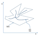
도 5a는 과노출 영역의 골격의 예를 예시한다.
도 5b는 과노출 영역의 골격의 예를 예시한다.
도 5c는 과노출 영역의 골격의 예를 예시한다.
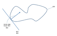
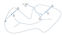
도 6은 과노출 영역의 접선 및 접선에 대한 직교 벡터의 예를 예시한다.
도 7은 과노출 영역의 후보 픽셀들의 예를 예시한다.
도 8은 과노출 영역 및 섹터들의 예를 예시한다.
도 9는 본 원리들에 따른 예시적인 장치를 도시하는 다이어그램이다.The features and advantages of the present invention will become apparent from the following detailed description when taken in conjunction with the accompanying drawings.
Figure 1 is a diagram illustrating an exemplary method in accordance with the present principles.
Figure 2 is a diagram illustrating an exemplary method in accordance with the present principles.
Figure 3 is a diagram illustrating an exemplary method in accordance with the present principles.
Figure 4A is a diagram illustrating an exemplary method in accordance with the present principles.
4B is a diagram illustrating an exemplary method according to the present principles.
5A illustrates an example of a skeleton of an overexposed region.
FIG. 5B illustrates an example of the skeleton of the overexposed region.
FIG. 5C illustrates an example of the skeleton of the overexposed region.
Figure 6 illustrates an example of an orthogonal vector for the tangent and tangent of the overexposed area.
Figure 7 illustrates an example of candidate pixels in the overexposed region.
Figure 8 illustrates an example of overexposed areas and sectors.
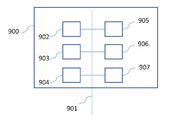
9 is a diagram illustrating an exemplary apparatus according to the present principles.
본 원리들은 과노출 이미지 영역(들)의 정정 및/또는 재구성을 위한 방법들, 장치 및 시스템들에 관한 것이다. 일 예에서, 과노출 영역(들)은 과노출 영역(들) 주변의 잘-노출된 픽셀들의 등광도선들을 분석함으로써 재구성될 수 있다.The present principles are directed to methods, apparatus and systems for correcting and / or reconstructing overexposed image region (s). In one example, the overexposed area (s) can be reconstructed by analyzing the equipotential lines of well-exposed pixels around the overexposed area (s).
본원에서 사용되는 바와 같이, "등광도선(isophote line)들"은 영역의 기울기에 직교하는 방향들을 가지는 라인들로서 정의될 수 있다. 본원에서 사용되는 바와 같이, "잘-노출된(well-exposed)" 픽셀들은 과노출 영역(들)의 일부분이 아닌 픽셀들로서 정의될 수 있다. "영역(region)"은 함께 그룹화되는 복수의 픽셀들로서 정의될 수 있다. 픽셀들은 그룹의 각각의 픽셀이 그룹의 적어도 하나의 다른 픽셀에 접속되는 경우 함께 그룹화된다. 이미지는 다수의 이러한 영역들을 가질 수 있다.As used herein, "isophote lines" may be defined as lines having directions orthogonal to the slope of the region. As used herein, "well-exposed" pixels may be defined as pixels that are not part of the overexposed area (s). A "region" may be defined as a plurality of pixels grouped together. Pixels are grouped together when each pixel in the group is connected to at least one other pixel in the group. An image can have many such areas.
클리핑된 또는 과노출된 이미지 영역들은 통상적으로, 1개, 2개 또는 3개의 컬러 채널들이 최대 표현가능한 픽셀 값에 도달한 영역들이다. 본 원리들의 양태는 모든 3개의 컬러 채널들이 최대 표현가능한 픽셀 값에 도달한 이미지 영역들의 재구성에 관한 것이다. 그러나, 단 1개 또는 2개의 채널들이 최대 픽셀 값들을 가지는 이미지 영역들은 추가적인 전처리 단계에 기초할 수 있다.Clipped or overexposed image areas are typically areas where one, two, or three color channels have reached the maximum representable pixel value. An aspect of these principles relates to the reconstruction of image regions in which all three color channels have reached a maximum representable pixel value. However, image areas with only one or two channels having maximum pixel values may be based on additional preprocessing steps.
본원에서 사용되는 바와 같이, 첨자 i 및 j는 상호교환가능하게 사용될 수 있다. 그러나, 두 첨자들 모두가 동일한 방정식에서 나타나는 경우, 이들은 상이한 세트들을 지시한다. 예를 들어, 세트 ![]()
![]()
![]()
![]()
![]()
![]()
![]()
![]()
![]()
![]()
본 원리들의 양태는 이미지 프로세싱 파이프라인 내의 과노출 영역들의 정정에 관한 것이다. 일 예에서, 본 원리들의 양태는 디바이스(예를 들어, 셋톱 박스, 컴퓨터, 태블릿, 스마트폰, 랩톱 또는 디스플레이를 위한 정보를 제공할 수 있는 임의의 다른 디바이스)에서의 과노출된 또는 클리핑된 영역들의 재구성에 관한 것이다. 일 예에서, SDR 이미지 콘텐츠는 HDR 디스플레이 디바이스에 대해 HDR로 전환된다. 또다른 예에서, 이미지의 과노출된 또는 클리핑된 영역들은 캡쳐 프로세스 동안 재구성될 수 있다. 예를 들어, (예를 들어, 카메라, 스마트폰에 의한) 이미지 캡쳐 동안, 이미지는 본 원리들에 따라 향상될 수 있다. 또다른 예에서, 본 원리들의 양태는 후반-제작 동안 과노출된 또는 클리핑된 영역들의 재구성에 관한 것이다. 본 원리들의 양태는 과노출 영역들에 대한 저주파수 재구성 알고리즘에 관한 것이다. 본 원리들의 양태는 영역의 형상 뿐만 아니라 과노출 영역의 바로 주변의 영역들로부터 취해진 정보를 고려함으로써 저주파수 휘도 프로파일을 과노출 영역에 피팅하는 것에 관한 것이다.Embodiments of the present principles are directed to the correction of overexposed areas in an image processing pipeline. In one example, aspects of the present principles may be applied to an overexposed or clipped region (e.g., a set top box, a computer, a tablet, a smartphone, a laptop, or any other device capable of providing information for a display) Lt; / RTI > In one example, the SDR image content is converted to HDR for the HDR display device. In another example, overexposed or clipped regions of an image may be reconstructed during the capture process. For example, during image capture (e.g., by a camera, a smartphone), the image may be enhanced according to the present principles. In another example, aspects of these principles relate to post-fabrication and reconstruction of exposed or clipped regions. Embodiments of these principles are directed to low frequency reconstruction algorithms for overexposed regions. Embodiments of the present principles are directed to fitting a low frequency luminance profile to an overexposed area by taking into account not only the shape of the area but also the information taken from areas immediately in the immediate vicinity of the exposed area.
본 원리들의 양태는 바람직하지 않은 시각적 주목을 감소시키기 위한 과노출 영역들의 휘도 정정 또는 재구성에 관한 것이다. 본 원리들의 양태는 과노출 영역들의 크기 및 형상, 뿐만 아니라 과노출 영역 주변의 잘-노출된 콘텐츠의 휘도 값들, 기울기 값들, 등광도선 방향들 및/또는 기울기 방향들과 같은 이미지 정보에 기초하여 과노출 영역들의 실제같은 재구성을 개선하는 것에 관한 것이다. 본 원리들의 양태는 최적화 프로세스에 기초하여 정정된 휘도 픽셀들을 비-정정 픽셀들과 끊김 없이 시각적으로 블렌딩하는 것에 관한 것이다.Embodiments of these principles relate to brightness correction or reconstruction of overexposed areas to reduce undesirable visual attention. Embodiments of the present principles may also be applied to other types of exposure based on image information, such as the size and shape of the overexposed areas, as well as the luminance values, tilt values, isoderm lines and / or tilt directions of the well- Lt; RTI ID = 0.0 > realization < / RTI > of the exposed areas. An aspect of the present principles relates to seamlessly blending corrected luminance pixels with non-correcting pixels seamlessly based on an optimization process.
도 1, 2 및 3은 예시적인 휘도 프로파일 재구성 방법들을 예시한다. 도 1은 휘도 프로파일 재구성을 위한 방법(100)을 예시한다. 방법(100)은 영역 특성화를 위한 블록(101)을 포함할 수 있다. 블록(101)은 입력 이미지에 대한 이미지 영역(들)의 형상들을 특성화할 수 있다. 블록(101)은 블록(102)에 제어를 전달할 수 있다. 블록(102)은 영역 정정을 수행할 수 있다. 선택적으로, 휘도 프로파일 재구성은 (예를 들어, 블록(101) 이전에) 이미지 다운샘플링 및 (예를 들어, 블록(102) 이후에) 이미지 업샘플링을 포함할 수 있다. 이러한 샘플링은 영역의 높은 공간 주파수들의 부재에 대해 책임질 수 있다. 더 낮은 픽셀 해상도들을 프로세싱함으로써 프로세싱 양이 감소할 수 있다.Figures 1, 2 and 3 illustrate exemplary luminance profile reconstruction methods. Figure 1 illustrates a
도 2는 휘도 프로파일 재구성을 수행하기 위한 방법(200)을 예시한다. 방법(200)은 입력 이미지를 다운샘플링하기 위한 블록(201)을 포함할 수 있다. 일 예에서, 블록(201)은 선택적일 수 있다. 블록(202)은 영역 특성화를 수행할 수 있다. 블록(203)은 과노출 영역(들) 각각을 분류함으로써 영역 특성화를 수행할 수 있다. 예를 들어, 블록(203)은 과노출 영역이 스페큘러 하이라이트, 확산 표면, 또는 광원이었는지를 결정할 수 있다. 전용 재구성 알고리즘은 블록(203)에 의해 결정된 표면 타입에 기초하여 결정될 수 있다. 예를 들어, 확산 영역에 대해, 블록(204)은 확산 표면 정정을 수행할 수 있다. 스페큘러 하이라이트 영역에 대해, 블록(205)은 스페큘러 하이라이트 영역 재구성을 수행할 수 있다. 광원에 대해, 블록(206)은 광원 정정을 수행할 수 있다. 블록들(204, 205 및 206)로부터 초래되는 정정은 병합되어(도 2의 블록(207)) 정정된 이미지를 생성할 수 있다. 블록(208)은 정정된 이미지를 입력 이미지의 해상도로 업샘플링할 수 있다. 일 예에서, 블록(208)은 선택적일 수 있다.Figure 2 illustrates a
본 원리들의 양태는 영역 특성화에 관한 것이다. 영역 특성화는 도 1의 블록(101) 및 도 2의 블록(202)에 의해 수행될 수 있다. 본 원리들의 양태는 영역 정정에 관한 것이다. 영역 정정은 도 1의 블록(102) 및 도 2의 블록들(204, 205 및 206) 중 하나 이상에 의해 수행될 수 있다.An aspect of these principles relates to domain characterization. Region characterization may be performed by
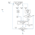
도 3은 본 원리들에 따른 영역 정정을 위한 예시적인 방법(300)을 예시한다. 방법(300)은 입력 이미지 1 (301)를 수신할 시에 시작할 수 있다. 일 예에서, 과노출 영역들의 식별과 같은, 이미지에 관한 추가 정보가 또한 제공될 수 있다. 각각의 영역은, 예를 들어, 마스크 ![]()
![]()
블록(302)은 각각의 과노출 영역(들)에 대한 골격을 결정할 수 있다. 일 예에서, 골격은 도 5a에 도시된 바와 같이 임의의 형상의 과노출 영역(501)에 대해 결정될 수 있다. 도 5a는 과노출 영역(501)에 대해 결정되는 예시적인 골격(502)을 예시한다.
일 예에서, 블록(302)은 중앙축 알고리즘에 기초하여 골격을 결정할 수 있다. 골격 위에 있는 과노출 영역 내의 픽셀들은 세트 ![]()
![]()
블록(302)에 의해 결정되는 골격은 과노출 영역의 형상의 중심이 평가됨을 나타낼 수 있다. 골격화는 과노출 영역을 가지는 2차원 휘도 프로파일의 피팅을 영역의 에지의 포인트들과 골격 상의 포인트들 사이의 1차원 휘도 프로파일의 하나 이상의 피팅들이 되도록 허용한다.The skeleton determined by
블록(303)은 블록(302)으로부터의 골격을 따라 휘도 값들을 결정할 수 있다. 블록(303)은 골격선(들)의 일부분인 각각의 픽셀에 대한 휘도 값들을 결정할 수 있다. 동일한 영역의 골격에 더하여 이용가능한 과노출 영역의 외곽선을 이용하여, 이 영역에 적용될 실제같은 휘도 프로파일은 통상적으로, 영역의 경계에서 최저 휘도 값들을 가지고, 골격의 픽셀 위치들에서 최고 휘도 값들을 가짐으로써 특성화될 것이다.
일 예에서, 블록(303)은 골격 위에 있는 픽셀들에 대한 피크 휘도 값들을 결정할 수 있다. 골격 위에 있는 픽셀들의 세트는 ![]()
![]()
일 예에서, 블록(303)은 하기에 수학식 번호 1, 3, 4, 6, 8, 9, 10, 11, 12 및 14와 관련하여 기술되는 원리들에 따라 각각의 픽셀 ![]()
![]()
![]()
![]()
![]()
![]()
일 예에서, 블록(303)은 세트 ![]()
![]()
![]()
![]()
특정된 값 ![]()
![]()
또다른 예에서, ![]()
![]()
![]()
![]()
![]()
![]()
![]()
![]()
![]()
![]()
![]()
![]()
![]()
![]()
![]()
![]()
![]()
![]()
![]()
![]()
![]()
![]()
![]()
![]()
![]()
![]()
![]()
![]()
또다른 예에서, 골격을 따르는 픽셀들 ![]()
![]()
![]()
![]()
![]()
![]()
![]()
![]()
![]()
![]()
수학식 3에서, ![]()
![]()
![]()
![]()
![]()
![]()
![]()
![]()
또다른 예에서, 골격 픽셀들 ![]()
![]()
![]()
![]()
![]()
![]()
![]()
![]()
![]()
![]()
![]()
![]()
![]()
![]()
![]()
![]()
여기서, 골격 픽셀들 ![]()
![]()
또다른 예에서, 선택적으로, 골격의 휘도는 골격의 휘도를 증가시키거나 감소시킬 수 있는 추가적인 재성형에 기초하여 결정될 수 있다. 일 예에서, 재성형은 과노출 영역의 분류 동안 결정되는 특징들에 기초할 수 있다. 예를 들어, 과노출 영역들은 광원, 스페큘러 하이라이트, 또는 확산 영역으로서 이들의 원천을 가지는 것으로서 분류될 수 있다. 이를 다음과 같이 쓸 수 있다:In another example, alternatively, the brightness of the framework can be determined based on additional re-shaping that can increase or decrease the brightness of the framework. In one example, re-shaping may be based on features determined during the classification of the over-exposure area. For example, overexposed regions can be classified as having a source of light, a specular highlight, or a diffusion region as their source. This can be written as:
![]()
![]()
여기서, Cr은 영역 ![]()
![]()
![]()
![]()
[수학식 5a](5a)

일 예에서, 골격 픽셀들의 휘도 값들은 과노출 영역 아래에 있는 예상되는 장면 콘텐츠의 분류에 기초하여 결정될 수 있다. 일 예에서, 골격 픽셀들의 휘도는 수학식 3에 기초하여, 수학식 5a에 제시된 바와 같은 영역 분류-특정 스케일링 인자 ![]()
![]()
![]()
![]()
수학식 4의 우항은 또한 수학식 5a에서 결정되는 스케일링 인자와 곱해져서 분류-특정 골격 휘도 값들을 구할 수 있다.The right term of Equation (4) can also be multiplied by the scaling factor determined in Equation (5a) to obtain the classification-specific skeleton luminance values.
일 예에서, 골격 픽셀들의 피크 휘도 값들은 세트 ![]()
![]()
본원에서 사용되는 바와 같이, 픽셀 ![]()
![]()
![]()
![]()
![]()
![]()
대안적으로, 기울기들은 후방 또는 중앙 차분 방식들에 기초하여 결정될 수 있다.Alternatively, the slopes may be determined based on backward or center differential schemes.
일 예에서, 기울기 정보를 사용하는 골격을 따르는 픽셀들의 피크 휘도는 과노출 영역 주변의 픽셀들에 기초하여 결정될 수 있다. 예를 들어, 피크 휘도는 ![]()
![]()
![]()
![]()
![]()
![]()
![]()
![]()
![]()
![]()
![]()
![]()
![]()
![]()
수학식 8은 세트 ![]()
![]()
![]()
![]()
에 기초하여, ![]()
![]()
![]()
![]()
![]()
![]()
![]()
![]()
![]()
![]()
![]()
![]()
![]()
![]()
![]()
![]()
![]()
![]()
![]()
![]()
![]()
![]()
일 예에서, 각각의 골격 픽셀은 골격 픽셀 ![]()
![]()
![]()
![]()
![]()
![]()
![]()
![]()
![]()
![]()
과노출 영역의 경계에 가까운 골격 픽셀들은 경계로부터 더 멀리 떨어진 골격 픽셀들보다 더 낮은 휘도를 유리하게 수신할 수 있다. 주어진 골격 픽셀에 대해, 과노출 영역의 에지까지의 최소 거리는 ![]()
![]()
![]()
![]()
![]()
![]()
수학식 11에서의 나머지 항목들은 수학식 8에서의 항목들과 동일하다. 마찬가지로, 수학식 9은 각각의 골격 픽셀의 그것의 영역의 경계까지의 거리를 고려하도록 수정될 수 있다. 결과적인 결정은 다음과 같이 표현될 수 있으며, 나머지 항목들은 수학식 9에서의 항목들과 동일하다:The remaining items in Equation (11) are the same as those in Equation (8). Similarly, equation (9) can be modified to take into account the distance to the boundary of its region of each skeletal pixel. The resulting decision can be expressed as follows, and the remaining items are the same as those in Equation 9:
![]()
![]()
수학식 11 및 12 내의 예들은 주어진 골격 픽셀 ![]()
![]()
![]()
![]()
![]()
![]()
![]()
![]()
![]()
![]()
![]()
![]()
![]()
![]()
![]()
![]()
![]()
![]()
![]()
![]()
에 따라 픽셀 ![]()
![]()
골격 픽셀들 ![]()
![]()
![]()
![]()
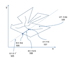
블록(304)은 각각의 과노출 영역(들)에 대한 에지 픽셀들을 결정할 수 있다. 일 예에서, 블록(304)은 각각의 과노출 영역 주위의 픽셀들의 링을 결정할 수 있다. 이러한 링 내의 픽셀들은 에지들과 같은 이미지 상세항목들을 제공할 수 있는데, 왜냐하면 이들이 휘도 및 컬러 변화를 포함하기 때문이다. 도 5b는 영역(501), 골격(502), 및 영역(501) 주위의 픽셀들의 링(503)을 예시한다. 픽셀들의 이러한 링(503)의 폭은 도 5b에서 504에 의해 식별될 수 있다. 픽셀들의 링의 폭은 ![]()
![]()
![]()
![]()
![]()
![]()
블록(304)에 의해 결정된 에지 픽셀들에 대해, 블록(306)은 기울기를 결정할 수 있고, 블록(305)은 하나 이상의 방향들을 결정할 수 있다. 일 예에서, 블록(305)은 방향들의 세트 ![]()
![]()
![]()
![]()
![]()
![]()
![]()
![]()
![]()
![]()
![]()
![]()
일 예에서, 블록(305)은 과노출 영역의 형상에 기초하여 세트 ![]()
![]()
![]()
![]()
![]()
![]()
또다른 예에서, 블록(305)은 ![]()
![]()
![]()
![]()
![]()
![]()
![]()
![]()
![]()
![]()
![]()
![]()
![]()
![]()
추가적인 예에서, 블록(305)은 등광도선 방향들에 기초하여 세트 P 내의 픽셀들에 대한 방향 벡터들 ![]()
![]()
![]()
![]()
![]()
![]()
수학식 15로부터 초래되는 등광도선 벡터들 ![]()
![]()
![]()
![]()
또한, 각각의 픽셀 ![]()
![]()
![]()
![]()
![]()
![]()
![]()
![]()
![]()
![]()
![]()
![]()
에 따라 결정될 수 있다.≪ / RTI >
이 예에서, 적절한 방향 벡터가 ![]()
![]()
![]()
![]()
![]()
![]()
![]()
![]()
이 예에서, 적절한 방향 벡터들은 ![]()
![]()
![]()
![]()
![]()
![]()
![]()
![]()
![]()
![]()
![]()
![]()
![]()
![]()
![]()
![]()
![]()
![]()
![]()
![]()
![]()
![]()
![]()
![]()
일 예에서, 블록(306)은 블록(304)에 의해 결정되는 에지 픽셀들에 대한 휘도 경사들을 결정할 수 있다. 일 예에서, 경사들의 세트 ![]()
![]()
![]()
![]()
![]()
![]()
![]()
![]()
![]()
![]()
![]()
![]()
블록(307)은 과노출 영역 내의 각각의 픽셀에 대한 휘도 값들을 결정할 수 있다. 블록(307)은 블록들(302, 303, 304, 305 및/또는 306)에 의해 결정되는 정보에 기초하여 과노출 영역(들)의 픽셀들의 휘도 값들을 정정 및/또는 재구성할 수 있다. 예를 들어, 블록(305)으로부터의 방향 벡터들은 과노출 영역에 대해 내부에 있는 픽셀들에 대한 휘도 값들을 합성하기 위해 사용될 수 있다.
일 예에서, 블록(307)은 하나 이상의 골격 픽셀들 ![]()
![]()
![]()
![]()
블록(307)에 따른 정정된 휘도 값들 ![]()
![]()
도 4a는 휘도 값들을 정정하기 위한 예시적인 방법(1000)을 예시한다. 일 예에서, 블록(307)은 방법(1000)에 따라 과노출 영역(들) 내의 픽셀(들)에 대한 정정된 휘도 값들을 결정할 수 있다. 방법(1000)은 (예를 들어, 블록(305)에 의해 결정되는) 방향 벡터들 ![]()
![]()
![]()
![]()
![]()
![]()
![]()
![]()
![]()
![]()
![]()
![]()
![]()
![]()
도 4a는 과노출 영역의 픽셀들에 대한 정정된 휘도 값들 ![]()
![]()
![]()
![]()
![]()
![]()
![]()
![]()
![]()
![]()
![]()
![]()
![]()
![]()
![]()
![]()
![]()
![]()
![]()
![]()
![]()
![]()
![]()
![]()
![]()
![]()
![]()
![]()
![]()
![]()
![]()
![]()
![]()
![]()
![]()
![]()
![]()
![]()
블록(1005)은 에지 픽셀 및 방향 벡터 ![]()
![]()
![]()
![]()
![]()
![]()
![]()
![]()
![]()
![]()
![]()
![]()
![]()
![]()
![]()
![]()
![]()
![]()
![]()
![]()
블록(1010)은 내부 픽셀들(1006)의 서브세트 내의 각각의 픽셀에 대한 정정된 휘도 값을 결정할 수 있다. 블록(1010)은 골격 픽셀 ![]()
![]()
![]()
![]()
![]()
![]()
![]()
![]()
블록(1012)은 블록(1002)에 의해 결정되는 픽셀 ![]()
![]()
도 4b는 과노출 영역의 픽셀들에 대한 정정된 휘도 값들 ![]()
![]()
![]()
![]()
블록(1104)은 내부 픽셀 o i (1003)에 대한 최적의 후보 에지 픽셀 ![]()
![]()
![]()
![]()
![]()
![]()
![]()
![]()
![]()
![]()
![]()
![]()
![]()
![]()
![]()
![]()
![]()
![]()
![]()
![]()
블록(1104)은:
![]()
![]()
에 기초하여 이 거리가 충분히 가까운지 또는 작은지를 결정할 수 있고, 여기서, ![]()
![]()
![]()
![]()
![]()
![]()
![]()
![]()
![]()
![]()
![]()
![]()
![]()
![]()
![]()
![]()
![]()
![]()
![]()
![]()
또다른 예에서, 블록(1104)은, 각각의 픽셀 ![]()
![]()
![]()
![]()
![]()
![]()
![]()
![]()
![]()
![]()
![]()
![]()
![]()
![]()
![]()
![]()
![]()
![]()
블록(1104)이 픽셀 ![]()
![]()
![]()
![]()
블록(1106)은 에지 픽셀 ![]()
![]()
![]()
![]()
![]()
![]()
![]()
![]()
![]()
![]()
![]()
![]()
![]()
![]()
![]()
![]()
![]()
![]()
![]()
![]()
![]()
![]()
![]()
![]()
![]()
![]()
대안적인 예에서, 블록(1104)은 각각의 픽셀 ![]()
![]()
![]()
![]()
![]()
![]()
![]()
![]()
![]()
![]()
![]()
![]()
![]()
![]()
![]()
![]()
![]()
![]()
![]()
![]()
![]()
![]()
![]()
![]()
![]()
![]()
![]()
![]()
블록(1108)이 골격 픽셀 ![]()
![]()
![]()
![]()
![]()
![]()
![]()
![]()
![]()
![]()
블록(1110)은 내부 픽셀 ![]()
![]()
![]()
![]()
![]()
![]()
![]()
![]()
![]()
![]()
블록(1112)은 블록(1102)에 의해 결정된 픽셀 ![]()
![]()
일 예에서, 블록들(1010, 1110 또는 307)은 에지 픽셀에서의 휘도 ![]()
![]()
![]()
![]()
![]()
![]()
![]()
![]()
![]()
![]()
여기서, ![]()
![]()
또다른 예에서, 블록(1010, 1110, 또는 307)은 골격 ![]()
![]()
![]()
![]()
![]()
![]()
![]()
![]()
![]()
![]()
![]()
![]()
![]()
![]()
![]()
![]()
![]()
![]()
또다른 예에서, 블록들(1010, 1110 또는 307)은 비-선형 보간에 기초하여 과노출 영역의 내부 픽셀 ![]()
![]()
![]()
![]()
여기서, 비선형 함수 ![]()
![]()
또다른 예에서, 블록들(1010, 1110 또는 307)은 단일 내부 픽셀 ![]()
![]()
![]()
![]()
![]()
![]()
여기서, ![]()
![]()
또다른 예에서, 블록들(1010, 1110 또는 307)은 과노출 영역의 분류에 기초하여 휘도 값들을 결정할 수 있다. 예를 들어, 과노출 영역이 영역 타입(예를 들어, 스페큘러 하이라이트, 확산 표면, 광원)에 기초하여 분류되는 경우, 휘도는 그에 따라 선택되는 비선형 스케일링 함수에 기초하여 결정될 수 있다. 일 예에서, 블록들(1010, 1110 또는 307)은 스페큘러 영역에 대해 비선형 함수에 기초하여 휘도를 결정할 수 있다. 일 예에서, 이 함수는 골격 픽셀들 근처에서 급격한 기울기를 가질 수 있다. 일 예에서, 블록들(1010, 1110 또는 307)은 다음:In another example, blocks 1010, 1110, or 307 may determine the luminance values based on the classification of the overexposed regions. For example, if overexposed areas are classified based on area type (e.g., specular highlight, diffuse surface, light source), the luminance may be determined based on the nonlinear scaling function selected accordingly. In one example, blocks 1010, 1110, or 307 may determine the luminance based on a non-linear function for the specular region. In one example, this function may have a steep slope near skeletal pixels. In one example, blocks 1010, 1110, or 307 may be:

에 기초하여 스페큘러 하이라이트 영역들에 대한 휘도를 결정할 수 있다.The brightness for the specular highlight areas can be determined.
일 예에서, 블록들(1010, 1110 또는 307)은 다음:In one example, blocks 1010, 1110, or 307 may be:
![]()
![]()
에 기초하여 확산 영역들에 대한 휘도를 결정할 수 있다.Lt; / RTI > can determine the brightness for the diffusion regions.
일 예에서, 블록들(1010, 1110 또는 307)은 다음:In one example, blocks 1010, 1110, or 307 may be:
![]()
![]()
에 기초하여 광원 영역들에 대한 휘도를 결정할 수 있다.The brightness of the light source regions can be determined.
블록(308)은 픽셀 보간을 수행할 수 있다. 휘도 정정 또는 재구성 이후, 과노출 영역 내의 일부 픽셀들은 아직 휘도 값들을 수신하지 않아서, 재구성된 휘도 프로파일 내에 갭을 남길 수 있다. 블록(308)은 과노출 영역 내의 나머지 갭들을 채울 수 있다. 블록(308)은 (양-)선형 보간을 수행할 수 있다. 또다른 예에서, 블록(308)은 고차 보간을 수행할 수 있다.
블록(309)은 픽셀 리파인을 수행할 수 있다. 픽셀 보간 이후, 과노출 영역 내의 모든 픽셀은 휘도 값![]()
![]()
블록(309)은 이웃하는 재구성된 픽셀들 사이의 일관성을 개선시키기 위한 픽셀 리파인을 수행할 수 있다. 블록(309)은 2D 어레이 또는 벡터 ![]()
![]()
![]()
![]()
![]()
![]()
에 따라 (![]()
![]()
![]()
![]()
수학식 27은 휘도 프로파일의 일관성을 개선하는 원하는 효과를 달성하기 위해 추가적인 제약들이 부과될 것을 요구한다. 수학식 28 내지 32는, 그 중 하나 이상이 수학식 27의 최적화에 추가될 수 있는, 제약들의 세트를 기술한다. 예를 들어, 블록(309)은 재구성된 휘도 값들이 에지 픽셀들 ![]()
![]()
![]()
![]()
여기서, ![]()
![]()
최적화 동안 블록(309)에 의해 고려될 수 있는 또다른 제약은, 출력 값들 ![]()
![]()
![]()
![]()
![]()
![]()
로서 공식화될 수 있고, 여기서 ![]()
![]()
최적화 동안 블록(309)에 의해 고려될 수 있는 또다른 제약은, 골격 픽셀들이 영역 내의 나머지 내부 픽셀들보다 더 높은 휘도 값들을 가질 것을 요구할 수 있다. 블록(309)은 각각의 스캔라인에 대한 이러한 제약을 개별적으로 포함할 수 있고, 따라서, 영역의 각각의 스캔라인에 대해, 제약은 다음:Another constraint that may be considered by the
![]()
![]()
과 같이 공식화될 수 있고, 여기서 ![]()
![]()
수학식 30의 제약이 스캔 라인들(즉, 픽셀 행들)에 대해 공식화된다. 블록(309)은 픽셀 열들에 작용하지만, 그렇지 않은 경우 수학식 30에 도시된 제약과 동일한, 추가적인 제약을 포함할 수 있다.The constraint of Equation 30 is formulated for the scan lines (i. E., Pixel rows).
![]()
![]()
최적화 동안 블록(309)에 의해 고려될 수 있는 또다른 제약은 과노출 영역 외부의 픽셀들로부터 골격 픽셀들로의 점진적, 단조 증가 트랜지션을 요구할 수 있다. 주어진 방향을 따른 각각의 픽셀 ![]()
![]()
![]()
![]()
![]()
![]()
을 초래한다.≪ / RTI >
블록(309)은 입력 이미지의 나머지(잘-노출된) 픽셀들과 병합되기에 적합한 이미지 내의 각각의 과노출 영역에 대한 평활화된 휘도 프로파일을 출력할 수 있다.
일 예에서, 블록(207)은 블록(309)에 의해 출력되는 재구성된 휘도 값들의, 입력 이미지의 잘 노출된 픽셀들과의 병합을 수행할 수 있다. 블록(207)은 과노출된 휘도 값들을 재구성된 휘도 값들로 대체할 수 있다. 일 예에서, 휘도 값들은 인페인팅 알고리즘의 출력과 병합될 수 있다. 일 예에서, 휘도 값들과 인페인팅 출력의 병합은 ![]()
![]()
![]()
![]()
![]()
![]()
![]()
![]()

수학식 33은 블록(309)에 의해 출력되는 재구성된 휘도 프로파일 및 인페인팅 방법의 출력이 가산적일 때 블록(207)에 의해 수행될 수 있다. 승산 방식(multiplicative approach)이 요구되는 경우, 과노출 영역 내의 각각의 픽셀에 대한 중간 휘도 값은 블록(207)에 의해 다음과 같이 결정될 수 있다:Equation 33 may be performed by

출력 RGB 컬러 값들은 이후:The output RGB color values are then:

를 이용하여 블록(207)에 의해 결정된다. 수학식 33, 34 및 35에 관해 기술되는 원리들은 색차 채널들에 영향을 주지 않고, 휘도 채널에 대해, 컬러 반대 공간(또는 색차로부터 휘도를 분리시키는 임의의 다른 공간)에서 수행될 수 있다.Is determined by
도 9는 도 1, 2 및 3 및 수학식 1 내지 32에 관련하여 기술되는 방법들을 구현하도록 구성될 수 있는 장치(900)의 예시적인 아키텍처를 나타낸다.FIG. 9 illustrates an exemplary architecture of an
장치(900)는 데이터 및 어드레스 버스(901)에 의해 함께 링크되는 후속하는 엘리먼트들을 포함한다:
- 예를 들어, DSP(또는 Digital Signal Processor)(디지털 신호 프로세서)인, 마이크로프로세서(902)(또는 CPU);A microprocessor 902 (or CPU), for example a DSP (or Digital Signal Processor) (a digital signal processor);
- ROM(또는 Read Only Memory)(판독 전용 메모리)(903);- ROM (or Read Only Memory) (read-only memory) 903;
- RAM(또는 Random Access Memory)(랜덤 액세스 메모리)(904);- RAM (or Random Access Memory) (Random Access Memory) 904;
- 애플리케이션으로부터, 전송할 데이터의 수신을 위한 I/O 인터페이스(905); 및An I /
- 배터리(906)(또는 다른 적절한 전원).- Battery 906 (or other suitable power source).
변형예에 따르면, 배터리(906)는 장치에 대해 외부에 있다. 언급된 메모리 각각에서, 명세서에서 사용되는 단어 <<레지스터>>는 작은 용량(일부 비트)의 영역 또는 매우 큰 영역(예를 들어, 전체 프로그램 또는 다량의 수신된 또는 디코딩된 데이터)에 대응할 수 있다. ROM(903)은 적어도 프로그램 및 파라미터들을 포함한다. 발명에 따른 방법들의 알고리즘은 ROM(903)에 저장된다. 스위치온될 때, CPU(902)은 RAM 내에 프로그램을 업로드시키고, 대응하는 명령들을 실행한다.According to a variant, the
RAM(904)은, 레지스터 내에, CPU(902)에 의해 실행되며 장치(900)의 스위치 온 이후 업로드되는 프로그램, 레지스터 내의 입력 데이터, 레지스터 내의 방법의 상이한 상태들에 있는 중간 데이터, 및 레지스터 내의 방법의 실행을 위해 사용되는 다른 변수들을 포함할 수 있다.The
본원에 기술되는 구현예들은 예를 들어, 방법 또는 프로세스, 장치, 소프트웨어 프로그램, 데이터 스트림, 또는 신호에서 구현될 수 있다. 단일 형태의 구현예의 상황에서 논의되었지만(예를 들어, 방법 또는 장치로서만 논의됨), 논의되는 특징들의 구현예는 또한 다른 형태(예를 들어, 프로그램)로 구현될 수 있다. 장치는, 예를 들어, 적절한 하드웨어, 소프트웨어 및 펌웨어에서 구현될 수 있다. 방법은, 예를 들어, 컴퓨터, 마이크로프로세서, 집적 회로, 또는 프로그래밍가능 논리 디바이스를 포함하는, 일반적으로 프로세싱 디바이스들을 지칭하는 예를 들어, 프로세서와 같은 장치에서 구현될 수 있다. 프로세서들은 또한, 예를 들어, 컴퓨터, 셀 폰, 휴대용/개인 디지털 정보 단말("PDA"), 및 최종-사용자들 사이의 정보의 통신을 용이하게 하는 통신 디바이스들을 포함한다.Implementations described herein may be implemented in, for example, a method or process, an apparatus, a software program, a data stream, or a signal. Although discussed in the context of a single form of implementation (for example, discussed only as a method or apparatus), the implementation of the features discussed may also be implemented in other forms (e.g., a program). The device may be implemented in, for example, suitable hardware, software, and firmware. The method may be implemented in an apparatus such as, for example, a processor, generally referred to as a processing device, including, for example, a computer, microprocessor, integrated circuit, or programmable logic device. The processors also include communication devices that facilitate communication of information between, for example, a computer, a cell phone, a portable / personal digital assistant ("PDA"), and end-users.
이미지 프로세싱의 특정 예에 따르면, 이미지 또는 픽처 I가 소스로부터 획득된다. 예를 들어, 소스는:According to a particular example of image processing, an image or a picture I is obtained from a source. For example, the source is:
- 로컬 메모리(903 또는 904), 예를 들어, 비디오 메모리 또는 RAM(또는 Random Access Memory)(랜덤 액세스 메모리), 플래시 메모리, ROM(Read Only Memory)(판독 전용 메모리), 하드 디스크;
- 저장 인터페이스(905), 예를 들어, 대용량 저장소, RAM, 플래시 메모리, ROM, 광학 디스크 또는 자기 지지대를 가지는 인터페이스;An interface having a
- 통신 인터페이스(905), 예를 들어, 유선 인터페이스(예를 들어, 버스 인터페이스, 광역 네트워크 인터페이스, 로컬 영역 네트워크 인터페이스) 또는 무선 인터페이스(예컨대, IEEE 802.11 인터페이스 또는 Bluetooth® 인터페이스); 및A
- 이미지 캡쳐 회로(예를 들어, 예컨대, CCD(또는 Charge-Coupled Device)(전하-결합 디바이스) 또는 CMOS(또는 상보적 금속-산화물 반도체))Image capture circuitry (e.g., a CCD (or Charge-Coupled Device) (charge-coupled device) or CMOS (or complementary metal-oxide semiconductor)
를 포함하는 세트에 속한다.≪ / RTI >
상이한 실시예들에 따르면, 디코딩된 이미지 ![]()
![]()
- 로컬 메모리(903 또는 904), 예를 들어, 비디오 메모리 또는 RAM 또는 플래시 메모리, 하드 디스크;
- 저장 인터페이스(905), 예를 들어, 대용량 저장소, RAM, 플래시 메모리, ROM, 광학 디스크 또는 자기 지지대;
- 통신 인터페이스(905), 예를 들어, 유선 인터페이스(예를 들어, 버스 인터페이스(예를 들어, USB(또는 Universal Serial Bus)(유니버설 직렬 버스), 광역 네트워크 인터페이스, 로컬 영역 네트워크 인터페이스, HDMI(High Definition Multimedia Interface)(고 해상도 멀티미디어 인터페이스) 인터페이스 또는 무선 인터페이스(예컨대, IEEE 802.11 인터페이스, Wi-Fi ® 또는 Bluetooth ® 인터페이스); 및- a
- 디스플레이- display
를 포함하는 세트에 속한다.≪ / RTI >
상이한 예들에 따르면, 비트스트림 BF 및/또는 F가 목적지에 송신된다. 예로서, 비트스트림 F 및 BF 중 하나 또는 비트스트림들 F 및 BF 모두는 로컬 또는 원격 메모리, 예를 들어, 비디오 메모리(904) 또는 RAM(904), 하드 디스크(903)에 저장된다. 변형예에서, 하나의 또는 두 비트스트림들 모두가 저장 인터페이스(905), 예를 들어 대용량 저장소, 플래시 메모리, ROM, 광학 디스크 또는 자기 지지대를 가지는 인터페이스에 송신되고 그리고/또는 통신 인터페이스(905), 예를 들어, 포인트 대 포인트 링크, 통신 버스, 포인트 대 멀티포인트 링크 또는 방송 네트워크에 대한 인터페이스를 통해 전송된다.According to different examples, the bit streams BF and / or F are transmitted to the destination. By way of example, either bitstreams F and BF or both bitstreams F and BF are stored in a local or remote memory, e.g.,
상이한 예들에 따르면, 비트스트림 BF 및/또는 F는 소스로부터 획득된다. 예시적으로, 비트스트림은 로컬 메모리, 예를 들어, 비디오 메모리(904), RAM(904), ROM(903), 플래시 메모리(903) 또는 하드 디스크(903)로부터 판독된다. 변형예에서, 비트스트림은 저장 인터페이스(905), 예를 들어, 대용량 저장소, RAM, ROM, 플래시 메모리, 광학 디스크 또는 자기 지지대를 가지는 인터페이스로부터 수신되고, 그리고/또는 통신 인터페이스(905), 예를 들어, 포인트 대 포인트 링크, 버스, 포인트 대 멀티포인트 링크 또는 방송 네트워크에 대한 인터페이스로부터 수신된다.According to different examples, the bit streams BF and / or F are obtained from a source. Illustratively, the bit stream is read from a local memory, e.g.,
상이한 예들에 따르면, 본 원리들에 따라 방법들을 구현하도록 구성되는 장치(900)는:According to different examples, an
- 모바일 디바이스;- mobile devices;
- 통신 디바이스;A communication device;
- 게임 디바이스;- a game device;
- 태블릿(또는 태블릿 컴퓨터);- Tablet (or tablet computer);
- 랩톱;- Laptop;
- 스틸 이미지 카메라;- Still image camera;
- 비디오 카메라;- a video camera;
- 인코딩 칩;- encoding chip;
- 스틸 이미지 서버; 및- Still image server; And
- 비디오 서버(예를 들어, 방송 서버, 주문형 비디오(video-on-demand) 서버 또는 웹 서버)A video server (e.g., a broadcast server, a video-on-demand server, or a web server)
를 포함하는 세트에 속한다.≪ / RTI >
상이한 예들에 따르면, 본 원리들에 따라 이미지 프로세싱 프로세스를 구현하도록 구성되는 장치(900)는:According to different examples, an
- 모바일 디바이스;- mobile devices;
- 통신 디바이스;A communication device;
- 게임 디바이스;- a game device;
- 셋톱 박스;- set-top box;
- TV 세트;- TV set;
- 태블릿(또는 태블릿 컴퓨터);- Tablet (or tablet computer);
- 랩톱;- Laptop;
- 디스플레이; 및- display; And
- 디코딩 칩- Decoding chip
을 포함하는 세트에 속한다.. ≪ / RTI >
본원에 기술되는 다양한 프로세스들 및 특징들의 구현예들은 다양한 상이한 장비 또는 애플리케이션들에서 구현될 수 있다. 이러한 장비의 예들은 인코더, 디코더, 디코더로부터의 출력을 프로세싱하는 후처리기, 인코더에 입력을 제공하는 전처리기, 비디오 코더, 비디오 디코더, 비디오 코덱, 웹 서버, 셋톱 박스, 랩톱, 개인용 컴퓨터, 셀 폰, PDA, 및 다른 통신 디바이스들을 포함한다. 명백해야 할 바와 같이, 장비는 이동식이며, 심지어 자동차에 설치될 수도 있다.Implementations of the various processes and features described herein may be implemented in a variety of different equipment or applications. Examples of such equipment include an encoder, a decoder, a post-processor that processes the output from the decoder, a preprocessor that provides input to the encoder, a video coder, a video decoder, a video codec, a web server, a set- , A PDA, and other communication devices. As will be apparent, the equipment is mobile and may even be installed in a vehicle.
추가로, 방법들은 프로세서에 의해 명령들이 수행됨으로써 구현될 수 있고, 이러한 명령들(및/또는 구현예에 의해 생성되는 데이터 값들)은 예를 들어, 집적 회로, 소프트웨어 캐리어 또는 예를 들어, 하드 디스크, 컴팩트 디스켓("CD"), 광학 디스크(예를 들어, 디지털 다목적 디스크 또는 디지털 비디오 디스크라고 종종 지칭되는 DVD와 같은), 랜덤 액세스 메모리("RAM"), 또는 판독-전용 메모리("ROM")과 같은 다른 저장 디바이스와 같은, 프로세서-판독가능 매체 상에 저장될 수 있다. 명령들은 프로세서-판독가능 매체 상에 유형적으로 구현되는 응용 프로그램을 형성할 수 있다. 명령들은, 예를 들어, 하드웨어, 펌웨어, 소프트웨어, 또는 조합일 수 있다. 명령들은, 예를 들어, 운영 체제, 별도의 애플리케이션, 또는 이들 둘의 조합에서 발견될 수 있다. 따라서, 프로세서는, 예를 들어, 프로세스를 수행하도록 구성되는 디바이스 및 프로세스를 실행하기 위한 명령들을 가지는 (저장 디바이스와 같은) 프로세서-판독가능 매체를 포함하는 디바이스 둘 모두로서 특성화될 수 있다. 또한, 프로세서-판독가능 매체는, 명령들에 더하여 또는 명령들 대신, 구현예에 의해 생성되는 데이터 값들을 저장할 수 있다.In addition, the methods may be implemented by instructions executed by a processor, and such instructions (and / or data values generated by the implementation) may be stored, for example, in an integrated circuit, a software carrier, , A compact disk ("CD"), an optical disk (such as a DVD often referred to as a digital versatile disk or digital video disk), a random access memory , ≪ / RTI > or other storage device, such as a memory card). The instructions may form an application tangibly embodied on the processor-readable medium. The instructions may be, for example, hardware, firmware, software, or a combination. The instructions may be found, for example, in an operating system, in a separate application, or a combination of both. Thus, a processor may be characterized, for example, as both a device configured to perform a process and a device comprising a processor-readable medium (such as a storage device) having instructions for executing the process. In addition, the processor-readable medium may store data values generated by an implementation in addition to or instead of the instructions.
본 기술분야의 통상의 기술자에게 명백할 바와 같이, 구현예들은, 예를 들어, 저장되거나 전송될 수 있는 정보를 수행하도록 포맷팅되는 다양한 신호들을 생성할 수 있다. 정보는, 예를 들어, 기술되는 구현예들 중 하나에 의해 생성되는 데이터, 또는 방법을 수행하기 위한 명령들을 포함할 수 있다. 예를 들어, 신호는 기술된 예의 구문분석(syntax)을 기록하거나 판독하기 위한 규정들을 데이터로서 반송하도록, 또는 기술된 예에 의해 기록되는 실제 구문분석-값들을 데이터로서 반송하도록 포맷팅될 수 있다. 이러한 신호는, 예를 들어, 전자기파로서(예를 들어, 스펙트럼의 라디오 주파수 부분을 사용하여) 또는 베이스밴드 신호로서 포맷팅될 수 있다. 포맷팅은, 예를 들어, 데이터 스트림을 인코딩하는 것 및 인코딩된 데이터 스트림을 이용하여 캐리어를 변조하는 것을 포함할 수 있다. 신호가 반송하는 정보는, 예를 들어, 아날로그 또는 디지털 정보일 수 있다. 신호는 공지된 바와 같이, 다양한 상이한 유선 또는 무선 링크들을 통해 전송될 수 있다. 신호는 프로세서-판독가능 매체에 저장될 수 있다.As will be apparent to those of ordinary skill in the art, implementations may generate various signals that are formatted, for example, to carry information that may be stored or transmitted. The information may include, for example, data generated by one of the implementations described, or instructions for performing the method. For example, the signal may be formatted to carry back the rules for recording or reading the syntax of the described example as data, or to return the actual parsing-values that are recorded by the described example as data. Such a signal may be formatted, for example, as an electromagnetic wave (e.g., using a radio frequency portion of the spectrum) or as a baseband signal. Formatting may include, for example, encoding the data stream and modulating the carrier using the encoded data stream. The information that the signal carries may be, for example, analog or digital information. The signal may be transmitted over a variety of different wired or wireless links, as is known. The signal may be stored in a processor-readable medium.
다수의 구현예들이 기술된다. 그럼에도, 다양한 수정들이 이루어질 수 있다는 것이 이해될 것이다. 예를 들어, 상이한 구현예들의 엘리먼트들이 조합되고, 보충되고, 수정되거나 제거되어, 다른 구현예들을 생성할 수 있다. 추가로, 통상의 기술자는, 다른 구조들 및 프로세스들이 개시된 것에 대해 치환될 수 있으며, 결과적인 구현예들이 적어도 실질적으로 동일한 방식(들)으로 적어도 실질적으로 동일한 기능(들)을 수행하여, 개시된 구현예들과 적어도 실질적으로 동일한 결과(들)를 달성할 것임을 이해할 것이다. 따라서, 이러한 그리고 다른 구현예들이 이 출원에 의해 참작된다.A number of implementations are described. Nevertheless, it will be understood that various modifications may be made. For example, elements of different implementations may be combined, supplemented, modified or eliminated to produce other implementations. Additionally, it is to be appreciated that the skilled artisan will appreciate that other structures and processes may be substituted for what is disclosed, and that the resulting implementations perform at least substantially the same function (s) in at least substantially the same manner Will achieve at least substantially the same result (s) as the examples. Accordingly, these and other implementations are contemplated by this application.
다수의 특정 상세항목들이 본 발명의 철저한 이해를 제공하기 위해 본원에서 설명된다. 그러나, 위의 예들이 이러한 특정 상세항목들 없이도 구현될 수 있음이 본 기술분야의 통상의 기술자에 의해 이해될 것이다. 다른 경우들에서, 널리-알려진 동작들, 컴포넌트들 및 회로들은 본 발명을 모호하게 하지 않기 위해 상세히 기술되지 않았다. 본원에 개시된 특정 구조적 및 기능적 상세항목들이 대표적이며, 본 발명의 범위를 반드시 제한하지는 않음이 인지될 수 있다.Many specific details are set forth herein to provide a thorough understanding of the present invention. However, it will be understood by those of ordinary skill in the art that the above examples may be implemented without these specific details. In other instances, well-known operations, components, and circuits have not been described in detail in order not to obscure the present invention. It is to be appreciated that the specific structural and functional details disclosed herein are exemplary and do not necessarily limit the scope of the invention.
본 발명의 다양한 예들은 하드웨어 엘리먼트들, 소프트웨어 엘리먼트들, 또는 이들 둘의 조합을 사용하여 구현될 수 있다. 일부 예들은, 머신에 의해 실행되는 경우, 머신이 예들에 따른 방법 및/또는 동작들을 수행하게 할 수 있는 명령 또는 명령들의 세트를 저장할 수 있는, 예를 들어, 컴퓨터 판독가능 매체 또는 물품을 사용하여 구현될 수 있다. 이러한 머신은, 예를 들어, 임의의 적절한 프로세싱 플랫폼, 컴퓨팅 플랫폼, 컴퓨팅 디바이스, 프로세싱 디바이스, 컴퓨팅 시스템, 프로세싱 시스템, 컴퓨터, 프로세서 등을 포함할 수 있고, 하드웨어 및/또는 소프트웨어의 임의의 적절한 조합을 사용하여 구현될 수 있다. 컴퓨터-판독가능 매체 또는 물품은, 예를 들어, 임의의 적절한 타입의 메모리 유닛, 메모리 디바이스, 메모리 물품, 메모리 매체, 저장 디바이스, 저장 물품, 저장 매체 및/또는 저장 유닛을 포함할 수 있다. 명령들은, 임의의 적절한 고-레벨, 저-레벨, 객체-지향적, 시각적, 컴파일링된 그리고/또는 분석된 프로그래밍 언어를 사용하여 구현되는, 소스 코드, 컴파일 코드, 분석된 코드, 실행가능 코드, 정적 코드, 동적 코드, 암호화된 코드 등과 같은, 임의의 적절한 타입의 코드를 포함할 수 있다.Various examples of the present invention may be implemented using hardware elements, software elements, or a combination of both. Some examples are described using a computer readable medium or article that, when executed by a machine, is capable of storing a set of instructions or instructions that may cause the machine to perform the methods and / Can be implemented. Such a machine may include any suitable processing platform, computing platform, computing device, processing device, computing system, processing system, computer, processor, and / or the like, and may include any suitable combination of hardware and / ≪ / RTI > The computer-readable medium or article may comprise, for example, any suitable type of memory unit, memory device, memory article, memory medium, storage device, storage article, storage medium and / or storage unit. The instructions may be in the form of source code, compiled code, analyzed code, executable code, executable code, etc., which are implemented using any suitable high-level, low-level, object-oriented, visual, compiled and / For example, static code, dynamic code, encrypted code, and the like.
본원에 기술되는 구현예들은, 예를 들어 방법 또는 프로세스, 장치, 소프트웨어 프로그램, 데이터 스트림 또는 신호에서 구현될 수 있다. 단일 형태의 구현예의 상황에서만 논의되었지만(예를 들어, 방법으로서만 논의되었지만), 논의되는 특징들의 구현예는 또한 다른 형태들(예를 들어, 장치 또는 프로그램)로 구현될 수 있다. 장치 및 그 내에 포함되는 구성요소들, 예를 들어, 프로세서, 인코더 및 디코더는, 예를 들어, 적절한 하드웨어, 소프트웨어 및 펌웨어에서 구현될 수 있다. 방법들은 예를 들어, 컴퓨터, 마이크로프로세서, 집적 회로, 또는 프로그래밍가능 논리 디바이스를 포함하는, 예를 들어, 일반적으로 프로세싱 디바이스들을 지칭하는 프로세서와 같은, 예를 들어, 장치에서 구현될 수 있다. 프로세서들은 또한, 예를 들어, 컴퓨터, 셀 폰, 휴대용/개인 디지털 보조단말("PDA"), 및 최종-사용자들 사이에서의 정보의 통신을 용이하게 하는 다른 디바이스들과 같은, 통신 디바이스들을 포함한다.Implementations described herein may be implemented in, for example, a method or process, an apparatus, a software program, a data stream, or a signal. Although discussed only in the context of a single form of implementation (e.g., discussed only as a method), an implementation of the features discussed may also be implemented in other forms (e.g., a device or a program). The apparatus and the components contained therein, for example, a processor, an encoder and a decoder, may be implemented in, for example, suitable hardware, software and firmware. The methods may be implemented in, for example, a device, such as, for example, a processor generally referred to as a processing device, including, for example, a computer, microprocessor, integrated circuit, or programmable logic device. The processors also include communication devices, such as, for example, computers, cell phones, portable / personal digital assistants ("PDAs"), and other devices that facilitate communication of information between end- do.
추가로, 이 출원 또는 그 청구항들은 다양한 정보 피스들을 "결정하는" 것을 지칭할 수 있다. 정보의 결정은 예를 들어, 정보를 추정하는 것, 정보를 계산하는 것, 정보를 예측하는 것, 또는 메모리로부터 정보를 검색하는 것 중 하나 이상을 포함할 수 있다.In addition, this application or claims may refer to "determining " various information pieces. The determination of information may include, for example, one or more of estimating the information, calculating the information, predicting the information, or retrieving information from the memory.
또한, 이 출원 및 그 청구항들은 다양한 정보 피스들에 "액세스하는" 것을 지칭할 수 있다. 정보에 액세스하는 것은, 예를 들어, 정보를 수신하는 것, (예를 들어, 메모리로부터) 정보를 검색하는 것, 정보를 저장하는 것, 정보를 프로세싱하는 것, 정보를 전송하는 것, 정보를 이동시키는 것, 정보를 복제하는 것, 정보를 삭제하는 것, 정보를 계산하는 것, 정보를 결정하는 것, 정보를 예측하는 것, 또는 정보를 추정하는 것 중 하나 이상을 포함할 수 있다.In addition, this application and its claims may refer to "accessing " various information pieces. Accessing information may include, for example, receiving information, retrieving information (e.g., from memory), storing information, processing information, transferring information, May include one or more of moving, copying information, deleting information, calculating information, determining information, predicting information, or estimating information.
추가로, 이 출원 및 그 청구항들은 다양한 정보 피스들을 "수신하는" 것을 지칭할 수 있다. 수신하는 것은, "액세스하는" 것과 마찬가지로, 넓은 용어이도록 유도된다. 정보를 수신하는 것은 예를 들어, 정보에 액세스하는 것, 또는 (예를 들어, 메모리로부터) 정보를 검색하는 것 중 하나 이상을 포함할 수 있다. 또한, "수신하는" 것은 예를 들어, 정보를 저장하는 것, 정보를 프로세싱하는 것, 정보를 전송하는 것, 정보를 이동시키는 것, 정보를 복제하는 것, 정보를 삭제하는 것, 정보를 계산하는 것, 정보를 결정하는 것, 정보를 예측하는 것, 또는 정보를 추정하는 것과 같은 동작들 동안 한 방식으로 또는 또다른 방식으로 통상적으로 수반된다.In addition, this application and its claims may refer to "receiving " various information pieces. Receiving is induced to be a broad term as well as "accessing ". Receiving information may include, for example, one or more of accessing information, or retrieving information (e.g., from memory). Also, "receiving" may include, for example, storing information, processing information, transferring information, moving information, replicating information, deleting information, In one way or another during operations such as, for example, determining information, predicting information, or estimating information.
Claims (15)
표준 동적 범위(standard dynamic range)(SDR) 이미지로부터 결정되는 과노출 영역의 적어도 한 픽셀에 대한 정정된 휘도 값을 결정하는 단계를 포함하고,
상기 정정된 휘도 값은 상기 과노출 영역의 형상, 및 상기 과노출 영역을 둘러싸는 픽셀들의 에지 정보 중 적어도 하나에 기초하여 결정되는, 방법.An image processing method comprising:
Determining a corrected luminance value for at least one pixel of an overexposed area determined from a standard dynamic range (SDR) image,
Wherein the corrected luminance value is determined based on at least one of a shape of the overexposed area and edge information of pixels surrounding the overexposed area.
표준 동적 범위(standard dynamic range)(SDR) 이미지로부터 결정되는 과노출 영역의 적어도 한 픽셀에 대한 정정된 휘도 값을 결정하도록 구성되는 프로세서
를 포함하고, 상기 정정된 휘도 값은 상기 과노출 영역의 형상, 및 상기 과노출 영역을 둘러싸는 픽셀들의 에지 정보 중 적어도 하나에 기초하여 결정되는, 장치.An apparatus for image processing,
A processor configured to determine a corrected luminance value for at least one pixel of the overexposed region determined from a standard dynamic range (SDR) image,
Wherein the corrected luminance value is determined based on at least one of a shape of the overexposed area and edge information of pixels surrounding the overexposed area.
상기 과노출 영역은 불규칙적 형상의 영역인, 방법 또는 장치.3. The method according to claim 1 or 2,
Wherein the overexposed region is an area of irregular shape.
상기 과노출 영역의 타입을 결정하는 것 및 상기 과노출 영역의 타입에 기초하여 정정된 휘도를 결정하는 것을 더 포함하는, 방법 또는 장치.3. The method according to claim 1 or 2,
Further comprising determining a type of the overexposed area and determining a corrected luminance based on the type of the overexposed area.
상기 타입은 스페큘러(specular) 하이라이트 영역, 확산 또는 광원들 중 하나인, 방법 또는 장치.5. The method of claim 4,
Wherein the type is one of a specular highlight area, diffuse or light sources.
상기 휘도는 상기 과노출 영역의 골격에 기초하여 정정되는, 방법 또는 장치.3. The method according to claim 1 or 2,
Wherein the brightness is corrected based on the skeleton of the over-exposed area.
휘도는 상기 골격을 따르는 픽셀들의 피크 휘도에 기초하여 정정되는, 방법 또는 장치.3. The method according to claim 1 or 2,
Wherein the luminance is corrected based on the peak luminance of the pixels along the skeleton.
휘도는 상기 과노출 구역을 둘러싸는 픽셀들의 링에 기초하여 정정되는, 방법 또는 장치.3. The method according to claim 1 or 2,
Wherein the luminance is corrected based on the ring of pixels surrounding the overexposed area.
상기 휘도는 상기 픽셀들의 링에 기초하여 결정되는 에지들에 기초하여 정정되는, 방법 또는 장치.9. The method of claim 8,
Wherein the brightness is corrected based on edges determined based on the ring of pixels.
상기 휘도는 상기 픽셀들의 링에 기초하여 결정되는 방향 벡터들에 기초하여 정정되는, 방법 또는 장치.9. The method of claim 8,
Wherein the brightness is corrected based on direction vectors determined based on the ring of pixels.
상기 방향 벡터들은 상기 픽셀들의 링의 등광도선 벡터(isophote vector)들에 기초하여 결정되는, 방법 또는 장치.11. The method of claim 10,
Wherein the direction vectors are determined based on isophote vectors of the ring of pixels.
상기 방향 벡터들은 상기 픽셀들의 링의 기울기(gradient)들에 기초하여 결정되는, 방법 또는 장치.11. The method of claim 10,
Wherein the direction vectors are determined based on the rings' slopes of the pixels.
휘도는 에지 픽셀에서의 휘도
과 같이 정정되는, 방법 또는 장치.3. The method according to claim 1 or 2,
The luminance is the luminance at the edge pixel
/ RTI >
휘도는 골격에서의 휘도

과 같이 정정되는, 방법 또는 장치.3. The method according to claim 1 or 2,
The luminance is the luminance in the skeleton
/ RTI >
최적화, 즉,
최적화된 휘도 값들
중 하나 이상을 받는
Optimization, that is,
Optimized luminance values
Receiving one or more of
Applications Claiming Priority (2)
| Application Number | Priority Date | Filing Date | Title |
|---|---|---|---|
| EP15306350.8A EP3139342A1 (en) | 2015-09-02 | 2015-09-02 | Methods, systems and apparatus for over-exposure correction |
| EP15306350.8 | 2015-09-02 |
Publications (1)
| Publication Number | Publication Date |
|---|---|
| KR20170031033A true KR20170031033A (en) | 2017-03-20 |
Family
ID=54251459
Family Applications (1)
| Application Number | Title | Priority Date | Filing Date |
|---|---|---|---|
| KR1020160111738A KR20170031033A (en) | 2015-09-02 | 2016-08-31 | Methods, systems and apparatus for over-exposure correction |
Country Status (5)
| Country | Link |
|---|---|
| US (1) | US10032261B2 (en) |
| EP (3) | EP3139342A1 (en) |
| JP (1) | JP2017050864A (en) |
| KR (1) | KR20170031033A (en) |
| CN (1) | CN106485668A (en) |
Families Citing this family (17)
| Publication number | Priority date | Publication date | Assignee | Title |
|---|---|---|---|---|
| KR102234092B1 (en) * | 2013-12-27 | 2021-04-01 | 인터디지털 매디슨 페턴트 홀딩스 에스에이에스 | Method for inverse tone mapping of an image |
| EP3139342A1 (en) * | 2015-09-02 | 2017-03-08 | Thomson Licensing | Methods, systems and apparatus for over-exposure correction |
| US10366478B2 (en) * | 2016-05-18 | 2019-07-30 | Interdigital Ce Patent Holdings | Method and device for obtaining a HDR image by graph signal processing |
| EP3312798A1 (en) * | 2016-10-20 | 2018-04-25 | Thomson Licensing | Method and device for inverse tone mapping |
| CN107145871B (en) * | 2017-05-10 | 2019-03-19 | 重庆简华科技有限公司 | It is a kind of can gesture operation intelligent home control system |
| JP6955147B2 (en) * | 2017-07-13 | 2021-10-27 | 富士通株式会社 | Image processing device, image processing method, and image processing program |
| CN110232659B (en) * | 2018-03-06 | 2022-09-20 | 展讯通信(天津)有限公司 | Image color cast correction method and device and electronic equipment |
| US11100620B2 (en) | 2018-09-04 | 2021-08-24 | Apple Inc. | Hue preservation post processing for highlight recovery |
| KR102127760B1 (en) * | 2018-11-30 | 2020-06-29 | 고려대학교 산학협력단 | Device and method for inverse tone mapping using a single low dynamic range image, recording medium for performing the method |
| US11049224B2 (en) | 2018-12-05 | 2021-06-29 | Microsoft Technology Licensing, Llc | Automated real-time high dynamic range content review system |
| US11501415B2 (en) * | 2019-11-15 | 2022-11-15 | Huawei Technologies Co. Ltd. | Method and system for high-resolution image inpainting |
| CN110930335B (en) * | 2019-11-27 | 2023-03-31 | 维沃移动通信有限公司 | Image processing method and electronic equipment |
| CN111340721B (en) * | 2020-02-18 | 2021-02-12 | 国网电子商务有限公司 | Pixel correction method, device, equipment and readable storage medium |
| US11676390B2 (en) * | 2020-10-23 | 2023-06-13 | Huawei Technologies Co., Ltd. | Machine-learning model, methods and systems for removal of unwanted people from photographs |
| CN113313649B (en) * | 2021-06-01 | 2022-09-16 | 上海联影医疗科技股份有限公司 | Image reconstruction method and device |
| CN114785966B (en) * | 2022-06-21 | 2022-09-06 | 深圳比特微电子科技有限公司 | Exposure control method, shooting processing method, device and medium |
| CN115423723B (en) * | 2022-10-14 | 2023-04-21 | 哈尔滨市科佳通用机电股份有限公司 | Self-adaptive railway wagon anomaly detection training set image enhancement method |
Family Cites Families (10)
| Publication number | Priority date | Publication date | Assignee | Title |
|---|---|---|---|---|
| US5680230A (en) * | 1993-09-09 | 1997-10-21 | Canon Kabushiki Kaisha | Image processing method and apparatus thereof |
| JP4218723B2 (en) * | 2006-10-19 | 2009-02-04 | ソニー株式会社 | Image processing apparatus, imaging apparatus, image processing method, and program |
| US9299317B2 (en) * | 2008-01-07 | 2016-03-29 | Dolby Laboratories Licensing Corporation | Local multiscale tone-mapping operator |
| TWI538474B (en) * | 2011-03-15 | 2016-06-11 | 杜比實驗室特許公司 | Methods and apparatus for image data transformation |
| US8861851B2 (en) * | 2011-05-13 | 2014-10-14 | Dolby Laboratories Licensing Corporation | Color highlight reconstruction |
| JP6311868B2 (en) * | 2013-11-07 | 2018-04-18 | 株式会社Joled | Image processing circuit, image processing method, and display device |
| JP6439418B2 (en) * | 2014-03-05 | 2018-12-19 | ソニー株式会社 | Image processing apparatus, image processing method, and image display apparatus |
| MX357793B (en) * | 2014-06-23 | 2018-07-25 | Panasonic Ip Man Co Ltd | Conversion method and conversion apparatus. |
| EP3139342A1 (en) * | 2015-09-02 | 2017-03-08 | Thomson Licensing | Methods, systems and apparatus for over-exposure correction |
| US10397443B2 (en) * | 2016-03-01 | 2019-08-27 | Qualcomm Incorporated | Methods and systems for generating color remapping information supplemental enhancement information messages for video |
-
2015
- 2015-09-02 EP EP15306350.8A patent/EP3139342A1/en not_active Withdrawn
-
2016
- 2016-08-25 EP EP16185720.6A patent/EP3139344A1/en not_active Withdrawn
- 2016-08-25 EP EP17204431.5A patent/EP3306564A1/en not_active Withdrawn
- 2016-08-26 CN CN201610740136.5A patent/CN106485668A/en active Pending
- 2016-08-30 JP JP2016167464A patent/JP2017050864A/en not_active Withdrawn
- 2016-08-31 KR KR1020160111738A patent/KR20170031033A/en unknown
- 2016-09-02 US US15/255,662 patent/US10032261B2/en not_active Expired - Fee Related
Also Published As
| Publication number | Publication date |
|---|---|
| EP3139342A1 (en) | 2017-03-08 |
| US20170061592A1 (en) | 2017-03-02 |
| US10032261B2 (en) | 2018-07-24 |
| EP3306564A1 (en) | 2018-04-11 |
| JP2017050864A (en) | 2017-03-09 |
| CN106485668A (en) | 2017-03-08 |
| EP3139344A1 (en) | 2017-03-08 |
Similar Documents
| Publication | Publication Date | Title |
|---|---|---|
| KR20170031033A (en) | Methods, systems and apparatus for over-exposure correction | |
| Rao et al. | A Survey of Video Enhancement Techniques. | |
| KR101764943B1 (en) | High dynamic range image generation and rendering | |
| Bandoh et al. | Recent advances in high dynamic range imaging technology | |
| EP3168809B1 (en) | Image processing for hdr images | |
| US9299317B2 (en) | Local multiscale tone-mapping operator | |
| EP2368226B1 (en) | High dynamic range image combining | |
| US7149355B2 (en) | Image processing apparatus, image processing method, image processing program, and computer-readable record medium storing image processing program | |
| US20120269457A1 (en) | Method for Synthesizing a Virtual Image from a Reduced Resolution Depth Image | |
| KR102045538B1 (en) | Method for multi exposure image fusion based on patch and apparatus for the same | |
| US9129411B2 (en) | Upsampling in a tiered signal quality hierarchy | |
| US9280811B2 (en) | Multi-scale large radius edge-preserving low-pass filtering | |
| EP3203439B1 (en) | Method and device for reducing noise in a component of a picture | |
| KR20160102438A (en) | Method and device for tone-mapping a high dynamic range image | |
| Gryaditskaya et al. | Motion aware exposure bracketing for HDR video | |
| CN113781320A (en) | Image processing method and device, terminal equipment and storage medium | |
| KR20100053680A (en) | Image generation method, device, its program and recording medium stored with program | |
| CN113556582A (en) | Video data processing method, device, equipment and storage medium | |
| US20210327026A1 (en) | Methods and apparatus for blending unknown pixels in overlapping images | |
| Zhang et al. | Multi-scale-based joint super-resolution and inverse tone-mapping with data synthesis for UHD HDR video | |
| JP2016201800A (en) | Methods and devices for generating, encoding or decoding images with first dynamic range, and corresponding computer program products and computer-readable medium | |
| Froehlich et al. | Content aware quantization: Requantization of high dynamic range baseband signals based on visual masking by noise and texture | |
| EP3139341A1 (en) | Methods, systems and apparatus for specular highlight reconstruction | |
| CN114140348A (en) | Contrast enhancement method, device and equipment | |
| JP2019165434A (en) | Method and apparatus for generating hdr image with reduced clipped area |