KR20170030603A - Particle detection sensor, dust sensor, smoke detector, air purifier, ventilation fan, and air conditioner - Google Patents
Particle detection sensor, dust sensor, smoke detector, air purifier, ventilation fan, and air conditioner Download PDFInfo
- Publication number
- KR20170030603A KR20170030603A KR1020177003685A KR20177003685A KR20170030603A KR 20170030603 A KR20170030603 A KR 20170030603A KR 1020177003685 A KR1020177003685 A KR 1020177003685A KR 20177003685 A KR20177003685 A KR 20177003685A KR 20170030603 A KR20170030603 A KR 20170030603A
- Authority
- KR
- South Korea
- Prior art keywords
- light
- wall
- wedge
- detection sensor
- detection area
- Prior art date
Links
- 238000001514 detection method Methods 0.000 title claims abstract description 231
- 239000002245 particle Substances 0.000 title claims abstract description 163
- 239000000428 dust Substances 0.000 title claims description 61
- 239000000779 smoke Substances 0.000 title claims description 11
- 238000009423 ventilation Methods 0.000 title claims description 9
- 230000003287 optical effect Effects 0.000 claims abstract description 94
- 238000000034 method Methods 0.000 claims description 10
- 230000000452 restraining effect Effects 0.000 description 37
- 238000010438 heat treatment Methods 0.000 description 17
- 238000012986 modification Methods 0.000 description 13
- 230000004048 modification Effects 0.000 description 13
- 230000002238 attenuated effect Effects 0.000 description 9
- 239000000470 constituent Substances 0.000 description 7
- 238000000149 argon plasma sintering Methods 0.000 description 6
- 238000004140 cleaning Methods 0.000 description 6
- 239000000463 material Substances 0.000 description 6
- 239000011347 resin Substances 0.000 description 6
- 229920005989 resin Polymers 0.000 description 6
- 239000000443 aerosol Substances 0.000 description 4
- 238000010586 diagram Methods 0.000 description 4
- 238000001746 injection moulding Methods 0.000 description 4
- 239000002699 waste material Substances 0.000 description 4
- 238000009792 diffusion process Methods 0.000 description 3
- 230000000694 effects Effects 0.000 description 3
- 239000002184 metal Substances 0.000 description 3
- 230000001154 acute effect Effects 0.000 description 2
- 239000003990 capacitor Substances 0.000 description 2
- 239000011521 glass Substances 0.000 description 2
- -1 pollen Substances 0.000 description 2
- 229920000515 polycarbonate Polymers 0.000 description 2
- 239000004417 polycarbonate Substances 0.000 description 2
- 238000012545 processing Methods 0.000 description 2
- 230000000630 rising effect Effects 0.000 description 2
- 229920000122 acrylonitrile butadiene styrene Polymers 0.000 description 1
- 230000000903 blocking effect Effects 0.000 description 1
- 238000006243 chemical reaction Methods 0.000 description 1
- 239000000356 contaminant Substances 0.000 description 1
- 238000013461 design Methods 0.000 description 1
- 238000004049 embossing Methods 0.000 description 1
- 239000010419 fine particle Substances 0.000 description 1
- 239000012530 fluid Substances 0.000 description 1
- 230000012447 hatching Effects 0.000 description 1
- 230000031700 light absorption Effects 0.000 description 1
- 239000007788 liquid Substances 0.000 description 1
- 238000012423 maintenance Methods 0.000 description 1
- 239000003973 paint Substances 0.000 description 1
- 239000013618 particulate matter Substances 0.000 description 1
- 230000002093 peripheral effect Effects 0.000 description 1
- 239000000049 pigment Substances 0.000 description 1
- 230000001902 propagating effect Effects 0.000 description 1
- 230000002441 reversible effect Effects 0.000 description 1
- 239000004065 semiconductor Substances 0.000 description 1
- 238000005476 soldering Methods 0.000 description 1
- 239000007787 solid Substances 0.000 description 1
- 239000000758 substrate Substances 0.000 description 1
- 230000001629 suppression Effects 0.000 description 1
- 238000004381 surface treatment Methods 0.000 description 1
- XLYOFNOQVPJJNP-UHFFFAOYSA-N water Substances O XLYOFNOQVPJJNP-UHFFFAOYSA-N 0.000 description 1
Images


Classifications
-
- G—PHYSICS
- G01—MEASURING; TESTING
- G01N—INVESTIGATING OR ANALYSING MATERIALS BY DETERMINING THEIR CHEMICAL OR PHYSICAL PROPERTIES
- G01N15/00—Investigating characteristics of particles; Investigating permeability, pore-volume, or surface-area of porous materials
- G01N15/06—Investigating concentration of particle suspensions
-
- G—PHYSICS
- G08—SIGNALLING
- G08B—SIGNALLING OR CALLING SYSTEMS; ORDER TELEGRAPHS; ALARM SYSTEMS
- G08B17/00—Fire alarms; Alarms responsive to explosion
- G08B17/10—Actuation by presence of smoke or gases, e.g. automatic alarm devices for analysing flowing fluid materials by the use of optical means
- G08B17/103—Actuation by presence of smoke or gases, e.g. automatic alarm devices for analysing flowing fluid materials by the use of optical means using a light emitting and receiving device
- G08B17/107—Actuation by presence of smoke or gases, e.g. automatic alarm devices for analysing flowing fluid materials by the use of optical means using a light emitting and receiving device for detecting light-scattering due to smoke
-
- G01N15/075—
-
- G—PHYSICS
- G01—MEASURING; TESTING
- G01N—INVESTIGATING OR ANALYSING MATERIALS BY DETERMINING THEIR CHEMICAL OR PHYSICAL PROPERTIES
- G01N15/00—Investigating characteristics of particles; Investigating permeability, pore-volume, or surface-area of porous materials
- G01N2015/0042—Investigating dispersion of solids
- G01N2015/0046—Investigating dispersion of solids in gas, e.g. smoke
-
- G—PHYSICS
- G01—MEASURING; TESTING
- G01N—INVESTIGATING OR ANALYSING MATERIALS BY DETERMINING THEIR CHEMICAL OR PHYSICAL PROPERTIES
- G01N21/00—Investigating or analysing materials by the use of optical means, i.e. using sub-millimetre waves, infrared, visible or ultraviolet light
- G01N21/17—Systems in which incident light is modified in accordance with the properties of the material investigated
- G01N21/47—Scattering, i.e. diffuse reflection
- G01N21/49—Scattering, i.e. diffuse reflection within a body or fluid
- G01N21/53—Scattering, i.e. diffuse reflection within a body or fluid within a flowing fluid, e.g. smoke
-
- G—PHYSICS
- G01—MEASURING; TESTING
- G01N—INVESTIGATING OR ANALYSING MATERIALS BY DETERMINING THEIR CHEMICAL OR PHYSICAL PROPERTIES
- G01N2201/00—Features of devices classified in G01N21/00
- G01N2201/06—Illumination; Optics
- G01N2201/064—Stray light conditioning
- G01N2201/0642—Light traps; baffles
Abstract
검지 영역(DA)에 집광하도록 광을 출력하는 투광계(120)와, 검지 영역(DA)에 있어서의 입자(2)에 의한 투광계(120)로부터의 광의 산란광을 수광하는 수광계(130)와, 검지 영역(DA)을 사이에 두고 수광계(130)와 대향하는 위치에 마련된 광 트랩(50A)을 구비하고, 광 트랩(50A)은, 검지 영역(DA)을 향해 개구한 개구부(52A)가 마련된 폐공간(51A)과, 폐공간(51A)에 마련된 복수의 쐐기형 돌출부(115)를 갖고, 복수의 쐐기형 돌출부(115)는, 검지 영역(DA)으로부터 멀수록, 쐐기형의 선단과 저변의 거리가 짧다.A light projecting system 120 for outputting light to converge light on the detection area DA and a light receiving system 130 for receiving scattered light of light from the light projecting system 120 by the particles 2 in the detection area DA, And an optical trap 50A provided at a position facing the photosensing system 130 with the detection area DA therebetween and the optical trap 50A has an opening 52A opened toward the detection area DA And the plurality of wedge-shaped protrusions 115 are arranged in the closed space 51A so that the distance from the detection area DA to the wedge-shaped protrusions 115 The distance between the tip and base is short.

Description
본 발명은, 입자 검출 센서, 및, 입자 검출 센서를 구비하는 더스트 센서, 연기 감지기, 공기 청정기, 환기팬 및 에어컨 등의 기기에 관한 것이다.The present invention relates to a particle detection sensor and a dust sensor having a particle detection sensor, a smoke detector, an air purifier, a ventilation fan, and an air conditioner.
종래, 대기 중에 부유하는 입자(에어로졸)에 의해 산란된 광(산란광)을 검지함으로써, 입자를 검출하는 광 산란식 입자 검출 센서가 알려져 있다(예컨대, 특허 문헌 1 참조).BACKGROUND ART Conventionally, a light scattering type particle detection sensor that detects particles by detecting light (scattered light) scattered by particles (aerosols) floating in the atmosphere is known (see, for example, Patent Document 1).
특허 문헌 1에 기재된 광 산란식 입자 검출 센서는, 하우징(광학실) 내에 투광 소자와 수광 소자를 구비하는 광전식 입자 검출 센서이다. 해당 센서는, 측정 대상의 기체를 하우징 내에 넣고, 넣은 기체에 투광 소자로부터의 광을 조사하고, 그 산란광에 의해 기체에 포함되는 입자의 유무를 검출한다. 예컨대, 대기 중에 부유 하는 먼지, 화분(花粉), 연기, PM 2.5(미소 입자 형상 물질) 등의 입자를 검출할 수 있다.The light scattering type particle detection sensor disclosed in
(선행 기술 문헌)(Prior art document)
(특허 문헌)(Patent Literature)
(특허 문헌 1) 일본 특허 공개 평 11-248629호 공보(Patent Document 1) Japanese Patent Laid-Open No. 11-248629
그런데, 광 산란식 입자 검출 센서에서는, 입자에 의한 산란광 이외의 광(미광)이 수광 소자에 입사되면 오검출을 일으킨다. 따라서, 미광이 수광 소자에 입사되지 않도록 함으로써, 입자의 검출 정밀도를 향상시키는 것이 요망되고 있다.Incidentally, in the light scattering type particle detection sensor, when light (stray light) other than scattered light due to particles is incident on the light receiving element, erroneous detection is caused. Therefore, it is desired to improve the detection accuracy of the particles by preventing the stray light from being incident on the light receiving element.
그래서, 본 발명은, 입자의 검출 정밀도를 향상시킬 수 있는 입자 검출 센서 등을 제공하는 것을 목적으로 한다.It is therefore an object of the present invention to provide a particle detection sensor or the like capable of improving the detection precision of particles.
상기 목적을 달성하기 위해, 본 발명의 일 태양과 관련되는 입자 검출 센서는, 검지 영역에 집광하도록 광을 출력하는 투광계와, 상기 검지 영역에 있어서의 입자에 의한 상기 투광계로부터의 광의 산란광을 수광하는 수광계와, 상기 검지 영역을 사이에 두고 상기 수광계와 대향하는 위치에 마련된 제 1 광 트랩을 구비하고, 상기 제 1 광 트랩은, 상기 검지 영역으로 향해 개구한 제 1 개구부가 마련된 제 1 폐공간과, 상기 제 1 폐공간에 마련된 복수의 쐐기형 돌출부를 갖고, 상기 복수의 쐐기형 돌출부는, 상기 검지 영역으로부터 멀수록, 쐐기형의 선단과 저변의 거리가 짧다.In order to achieve the above object, a particle detection sensor according to an aspect of the present invention includes a light projecting system for outputting light so as to be condensed in a detection area, and a scattering light generator for generating scattered light of light from the light projecting system by particles in the detection area And a first optical trap provided at a position opposite to the photodetection system with the detection area interposed therebetween, wherein the first optical trap has a first opening provided with a first opening toward the detection area And a plurality of wedge-shaped protrusions provided in the first closed space. The distance between the tip of the wedge-shaped protrusion and the bottom side of the plurality of wedge-shaped protrusions is shorter the farther from the detection area.
또한, 본 발명의 일 태양과 관련되는 더스트 센서는, 상기 입자 검출 센서를 구비한다.Further, a dust sensor according to an aspect of the present invention includes the particle detection sensor.
또한, 본 발명의 일 태양과 관련되는 연기 감지기는, 상기 입자 검출 센서를 구비한다.Further, the smoke detector according to one aspect of the present invention includes the particle detection sensor.
또한, 본 발명의 일 태양과 관련되는 공기 청정기는, 상기 입자 검출 센서를 구비한다.The air purifier according to one aspect of the present invention includes the particle detection sensor.
또한, 본 발명의 일 태양과 관련되는 환기팬은, 상기 입자 검출 센서를 구비한다.Further, a ventilation fan according to an aspect of the present invention includes the particle detection sensor.
또한, 본 발명의 일 태양과 관련되는 에어컨은, 상기 입자 검출 센서를 구비한다.The air conditioner according to an aspect of the present invention includes the particle detection sensor.
본 발명과 관련되는 입자 검출 센서에 의하면, 입자의 검출 정밀도를 향상시킬 수 있다.According to the particle detection sensor of the present invention, the detection accuracy of the particles can be improved.
도 1은 본 발명의 실시의 형태와 관련되는 입자 검출 센서의 개관 사시도이다.
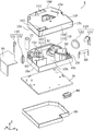
도 2는 본 발명의 실시의 형태와 관련되는 입자 검출 센서의 분해 사시도이다.
도 3은 본 발명의 실시의 형태와 관련되는 입자 검출 센서의 육면도이다.
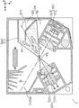
도 4는 본 발명의 실시의 형태와 관련되는 입자 검출 센서의 하우징 내부를 나타내는 단면도이다.
도 5는 본 발명의 실시의 형태와 관련되는 입자 검출 센서의 배면 커버의 내부 구조를 나타내는 개관 사시도이다.
도 6은 본 발명의 실시의 형태와 관련되는 입자 검출 센서의 전면 커버의 내부 구조를 나타내는 개관 사시도이다.
도 7은 본 발명의 실시의 형태와 관련되는 입자 검출 센서의 먼지 억제벽의 구조를 나타내는 단면도이다.
도 8은 본 발명의 실시의 형태와 관련되는 입자 검출 센서의 먼지 억제벽 및 제 2 광 트랩의 구조를 나타내는 단면도이다.
도 9는 본 발명의 실시의 형태와 관련되는 입자 검출 센서의 제 1 광 트랩의 구조를 나타내는 단면도이다.
도 10은 본 발명의 실시의 형태와 관련되는 입자 검출 센서의 투광계로부터 출사되는 광의 경로를 나타내는 도면이다.
도 11은 본 발명의 실시의 형태와 관련되는 입자 검출 센서의 제 2 광 트랩에 트랩되는 광의 경로를 나타내는 도면이다.
도 12는 본 발명의 실시의 형태와 관련되는 입자 검출 센서의 제 2 광 트랩에 트랩되는 다른 광의 경로를 나타내는 도면이다.
도 13은 본 발명의 실시의 형태와 관련되는 입자 검출 센서의 제 1 광 트랩에 트랩되는 광의 경로를 나타내는 도면이다.
도 14는 본 발명의 실시의 형태의 변형예와 관련되는 입자 검출 센서의 하우징 내부를 나타내는 단면도이다.
도 15는 본 발명의 실시의 형태와 관련되는 입자 검출 센서를 구비하는 연기 감지기의 외관도이다.
도 16은 본 발명의 실시의 형태와 관련되는 입자 검출 센서를 구비하는 공기 청정기의 외관도이다.
도 17은 본 발명의 실시의 형태와 관련되는 입자 검출 센서를 구비하는 환기팬의 외관도이다.
도 18은 본 발명의 실시의 형태와 관련되는 입자 검출 센서를 구비하는 에어컨의 외관도이다.1 is an outline perspective view of a particle detection sensor according to an embodiment of the present invention.
2 is an exploded perspective view of a particle detection sensor according to an embodiment of the present invention.
3 is a plan view of the particle detection sensor according to the embodiment of the present invention.
4 is a cross-sectional view showing the inside of a housing of a particle detection sensor according to an embodiment of the present invention.
5 is an outline perspective view showing the internal structure of the rear cover of the particle detection sensor according to the embodiment of the present invention.
6 is an outline perspective view showing an internal structure of a front cover of a particle detection sensor according to an embodiment of the present invention.
7 is a cross-sectional view showing the structure of the dust restraining wall of the particle detection sensor according to the embodiment of the present invention.
8 is a cross-sectional view showing the structure of the dust restraining wall and the second optical trap of the particle detection sensor according to the embodiment of the present invention.
9 is a cross-sectional view showing the structure of a first optical trap of a particle detection sensor according to an embodiment of the present invention.
10 is a diagram showing the path of light emitted from the light projecting system of the particle detection sensor according to the embodiment of the present invention.
11 is a view showing the path of light trapped in the second optical trap of the particle detection sensor according to the embodiment of the present invention.
12 is a view showing paths of other light trapped in the second optical trap of the particle detection sensor according to the embodiment of the present invention.
13 is a diagram showing the path of light trapped in the first optical trap of the particle detection sensor according to the embodiment of the present invention.
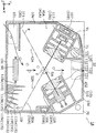
14 is a cross-sectional view showing the inside of a housing of a particle detection sensor according to a modification of the embodiment of the present invention.
15 is an external view of a smoke detector equipped with a particle detection sensor according to an embodiment of the present invention.
16 is an external view of an air cleaner equipped with a particle detection sensor according to an embodiment of the present invention.
17 is an external view of a ventilation fan equipped with a particle detection sensor according to an embodiment of the present invention.
18 is an external view of an air conditioner equipped with a particle detection sensor according to an embodiment of the present invention.
이하에서는, 본 발명의 실시의 형태와 관련되는 입자 검출 센서 등에 대하여, 도면을 이용하여 상세하게 설명한다. 또, 이하에 설명하는 실시의 형태는, 모두 본 발명의 바람직한 일 구체예를 나타내는 것이다. 따라서, 이하의 실시의 형태에서 나타내어지는 수치, 형상, 재료, 구성 요소, 구성 요소의 배치 및 접속 형태 등은, 일례이고, 본 발명을 한정하는 취지가 아니다. 따라서, 이하의 실시의 형태에 있어서의 구성 요소 중, 본 발명의 최상위 개념을 나타내는 독립 청구항에 기재되어 있지 않은 구성 요소에 대해서는, 임의의 구성 요소로서 설명된다.Hereinafter, a particle detection sensor according to an embodiment of the present invention will be described in detail with reference to the drawings. The embodiments described below all illustrate one preferred embodiment of the present invention. Therefore, the numerical values, shapes, materials, constituent elements, arrangement and connection forms of the constituent elements, and the like shown in the following embodiments are merely examples and do not limit the present invention. Therefore, among the constituent elements in the following embodiments, constituent elements which are not described in the independent claim that represents the highest concept of the present invention will be described as arbitrary constituent elements.
또한, 각 도면은, 모식도이고, 반드시 엄밀하게 도시된 것이 아니다. 또한, 각 도면에 있어서, 동일한 구성 부재에 대해서는 동일한 부호를 붙이고 있다.In addition, each drawing is a schematic diagram and is not necessarily strictly illustrated. In the drawings, the same constituent members are denoted by the same reference numerals.
(실시의 형태)(Embodiments)
[입자 검출 센서][Particle Detection Sensor]
우선, 본 실시의 형태와 관련되는 입자 검출 센서의 개요에 대하여 도 1~도 6을 이용하여 설명한다.First, the outline of the particle detection sensor according to the present embodiment will be described with reference to Figs. 1 to 6. Fig.
도 1~도 3은 각각, 본 실시의 형태와 관련되는 입자 검출 센서(1)를 나타내는 개관 사시도, 분해 사시도, 육면도이다. 구체적으로는, 도 3의 (a)는 입자 검출 센서(1)의 정면도, (b)는 배면도, (c)는 하면도, (d)는 상면도, (e)는 좌측면도, (f)는 우측면도이다.Figs. 1 to 3 are an opened perspective view, an exploded perspective view, and a top view, respectively, of the
도 4는 본 실시의 형태와 관련되는 입자 검출 센서(1)의 하우징(10)의 내부를 나타내는 단면도이고, 구체적으로는, 도 3의 (c)의 Ⅳ-Ⅳ선에 있어서의 단면을 나타내고 있다. 도 5 및 도 6은 각각, 본 실시의 형태와 관련되는 배면 커버(110) 및 전면 커버(100)의 내부 구조를 나타내는 개관 사시도이다.4 is a cross-sectional view showing the inside of the
입자 검출 센서(1)는, 유입구(101)가 아래쪽, 유출구(102)가 위쪽이 되도록 배치된다. 구체적으로는, 입자 검출 센서(1)는, 도 1에 나타내는 Y축 방향이 연직 위쪽이 되도록 배치된다. 또, 입자 검출 센서(1)는, 편평한 대략 직방체 형상이고, 서로 직교하는 2개의 변을 따른 방향을 각각 X축 방향 및 Y축 방향으로 한다. 또한, 입자 검출 센서(1)의 두께 방향을 Z축 방향으로 한다. 본 실시의 형태에서는, 입자 검출 센서(1)는, 예컨대, X : 52㎜×Y : 45㎜×Z : 22㎜에 들어가는 범위의 크기이다.The
입자 검출 센서(1)는, 도 1 및 도 4에 나타내는 바와 같이, 하우징(10)과, 하우징(10)의 내부에 배치된 광학계(20)를 구비하는 광전식 입자 검출 센서이다. 본 실시의 형태에서는, 입자 검출 센서(1)는, 광 산란식 입자 검출 센서이다. 구체적으로는, 입자 검출 센서(1)는, 광학계(20)가 하우징(10) 내의 검지 영역 DA에 광을 조사하고, 검지 영역 DA를 통과하는 입자(2)(에어로졸)에 의한 광의 산란광을 수광함으로써, 입자(2)의 유무를 검출한다. 또한, 입자 검출 센서(1)는, 입자(2)의 유무에 한하지 않고, 입자(2)의 개수 및 크기 등을 검출하더라도 좋다. 또, 입자 검출 센서(1)가 검출의 대상으로 하는 입자(2)는, 예컨대, 2㎛ 이하의 미소한 먼지, 화분, 연기, PM 2.5 등의 미립자이다.The
하우징(10)은, 광학계(20) 및 검지 영역 DA를 덮는 하우징(케이스)이다. 하우징(10)은, 광학계(20) 및 검지 영역 DA에 외광이 조사되지 않도록, 광학계(20) 및 검지 영역 DA를 덮고 있다.The
하우징(10)은, 내부에 입자(2)가 유입되기 위한 유입구(101)와, 내부에 유입된 입자(2)가 외부에 유출되기 위한 유출구(102)를 갖는다. 본 실시의 형태에서는, 도 4의 굵은 점선의 화살표로 나타내는 바와 같이, 입자(2)를 포함하는 기체가 유입구(101)로부터 유입되고, 하우징(10)의 내부(예컨대, 검지 영역 DA)를 지나 유출구(102)로부터 유출된다. 하우징(10)의 상세한 구성에 대해서는, 뒤에서 설명한다.The
광학계(20)는, 유입구(101)를 통해서 하우징(10) 내에 유입되고, 또한, 하우징(10)에 덮인 검지 영역 DA를 통과하는 입자(2)를 광학적으로 검출한다. 본 실시의 형태에서는, 도 4에 나타내는 바와 같이, 광학계(20)는, 하우징(10)에 덮인 검지 영역 DA에 서로의 광축(광축 P 및 광축 Q)이 교차하도록 배치된 투광계(120) 및 수광계(130)를 갖고, 검지 영역 DA를 통과하는 입자(2)를, 투광계(120)가 출력하는 광을 이용하여 검출한다. 투광계(120)는, 투광 소자(121)와, 투광 렌즈(122)를 구비한다. 수광계(130)는, 수광 소자(131)와, 수광 렌즈(132)를 구비한다. 광학계(20)의 상세한 구성에 대해서는, 뒤에서 설명한다.The
또, 검지 영역(광 산란부) DA는, 측정 대상의 기체에 포함되는 입자(2)를 검지하기 위한 영역인 에어로졸 검지 영역(에어로졸 측정부)이다. 본 실시의 형태에서는, 검지 영역 DA는, 투광계(120)의 광축 P와 수광계(130)의 광축 Q가 교차하는 교점을 포함하는 영역이다. 검지 영역 DA는, 예컨대, φ2㎜이다. 측정 대상의 기체는, 하우징(10)의 유입구(101)로부터 유입되고, 검지 영역 DA에 유도된 후, 유출구(102)로부터 유출된다.The detection area (light scattering part) DA is an aerosol detection area (aerosol detection part) which is an area for detecting the
입자 검출 센서(1)는, 도 1, 도 2 및 도 4에 나타내는 바와 같이, 먼지 억제벽(30)과, 광 트랩(제 2 광 트랩)(40)과, 광 트랩(제 1 광 트랩)(50)과, 가열 장치(60)와, 회로 기판(70)과, 커넥터(80)와, 실드 커버(90)와, 실드 커버(91)를 더 구비한다.1, 2 and 4, the
먼지 억제벽(30)은, 유입구(101)와 검지 영역 DA의 사이에 마련된 벽으로서, 입자(2)보다 큰 먼지가 검지 영역 DA에 진입하는 것을 억제한다. 여기서, 검지 영역 DA로의 진입을 억제하기 위한 대상이 되는 먼지(진애)는, 예컨대, 2㎛ 이상의 입자이다.The
또한, 먼지 억제벽(30)은, 유입구(101)와 광 트랩(40)의 사이에 마련된 벽으로서, 기체가 광 트랩(40)에 진입하지 않도록 기체를 유도하는 기체 유도벽이다. 먼지 억제벽(30)의 상세한 구성에 대해서는, 뒤에서 설명한다.The
광 트랩(40)은, 투광계(120)로부터 출력되어 검지 영역 DA를 통과한 광을 트랩한다. 구체적으로는, 광 트랩(40)은, 내부에 일단 입사된 광이 외부로 출사되지 않도록 흡수한다. 본 실시의 형태에서는, 광 트랩(40)은, 미로 구조로서 쐐기형의 폐공간을 갖는다.The
광 트랩(40)은, 제 2 광 트랩의 일례이고, 검지 영역 DA를 사이에 두고 투광계(120)와 대향하는 위치에 마련되어 있다. 구체적으로는, 광 트랩(40)은, 복수의 개구부(42, 44)를 갖고, 투광계(120)로부터 출력되어 검지 영역 DA를 통과한 광을, 복수의 개구부(42, 44)의 각각을 통과하도록 분할하고 나서 트랩한다. 광 트랩(40)의 상세한 구성에 대해서는, 뒤에서 설명한다.The
광 트랩(50)은, 광 트랩(40)에 트랩되지 않는 광을 트랩한다. 예컨대, 광 트랩(50)은, 투광계(120)로부터 출력되어 검지 영역 DA를 지나지 않는 광(누설광), 및, 광 트랩(40)에 일단 입사되었지만 다시 광 트랩(40)으로부터 출사된 광 등을 트랩한다.The light trap (50) traps light that is not trapped in the light trap (40). For example, the
광 트랩(50)은, 제 1 광 트랩의 일례이고, 검지 영역 DA를 사이에 두고 수광계(130)와 대향하는 위치에 마련되어 있다. 광 트랩(50)은, 예컨대, 복수의 쐐기형 돌출부(115)가 마련된 미로 구조이다. 광 트랩(50)의 상세한 구성에 대해서는, 뒤에서 설명한다.The
가열 장치(60)는, 유입구(101)로부터 유입된 입자(2)를 포함하는 기체를, 검지 영역 DA를 통과하도록 흘림으로써, 하우징(10) 내에 기류를 생성하는 기류 생성부의 일례이다. 본 실시의 형태에서는, 가열 장치(60)는, 하우징(10)의 하부에 배치되어, 대기를 가열하는 히터이다. 구체적으로는, 가열 장치(60)는, 입자(2)를 포함하는 기체를 가열함으로써, 도 4에 나타내는 바와 같이, 하우징(10) 내에 상승 기류(Y축 정방향으로의 기체의 흐름)를 생성하고, 검지 영역 DA에 입자(2)를 포함하는 기체를 유도한다. 가열 장치(60)는, 예컨대, 낮은 비용의 히터 저항이다. 또, 도 4에서는, 굵은 점선의 화살표로 기류의 일례를 나타내고 있다.The
회로 기판(70)은, 입자 검출 센서(1)의 제어 회로가 형성된 프린트 배선 기판이다. 제어 회로는, 예컨대, 투광계(120)에 의한 광의 출력, 수광계(130)에 의해 수광한 광 신호에 근거하는 전기 신호의 처리, 가열 장치(60)에 의한 기체의 가열 등의 처리를 제어한다. 예컨대, 제어 회로는, 입자(2)의 유무, 크기 및 개수 등을 검출하고, 커넥터(80)를 통해서 외부에 검출 결과를 출력한다.The
회로 기판(70)은, 예컨대, 직사각형의 평판이고, 한쪽의 주면(표면)에 하우징(10)이 고정되어 있다. 다른 쪽의 주면(이면)에는, 제어 회로를 구성하는 1개 또는 복수의 회로 소자(회로 부품)가 실장되어 있다. 또, 투광 소자(121), 수광 소자(131) 및 가열 장치(60)(히터 저항)의 각각의 전극 단자는, 하우징(10)의 배면 커버(110) 및 회로 기판(70)을 관통하고, 회로 기판(70)의 이면에 납땜되어 있다. 이것에 의해, 투광 소자(121), 수광 소자(131) 및 가열 장치(60)(히터 저항)의 각각은, 제어 회로에 전기적으로 접속되고, 제어 회로에 의해 동작이 제어된다.The
복수의 회로 소자는, 예컨대, 저항, 콘덴서, 코일, 다이오드 또는 트랜지스터 등을 포함한다. 복수의 회로 소자의 하나인 전해 콘덴서(71)는, 도 4 및 도 5에 나타내는 바와 같이, 회로 기판(70)의 표면에 마련되어, 하우징(10) 내에 배치되어 있다.The plurality of circuit elements include, for example, a resistor, a capacitor, a coil, a diode, a transistor, or the like. As shown in Figs. 4 and 5, the
이와 같이, 하우징(10) 내의 공간을 유효하게 이용함으로써, 회로 기판(70)의 이면 쪽에 배치하는 회로 소자를 적게 할 수 있다. 이것에 의해, 회로 기판(70)의 이면 쪽의 회로 소자용의 공간을 작게 할 수 있고, 실드 커버(90)를 작게 할 수 있다. 따라서, 입자 검출 센서(1)를 소형화할 수 있다.By effectively using the space in the
커넥터(80)는, 입자 검출 센서(1)의 제어 회로(회로 기판(70))와, 외부의 제어 회로 또는 전원 회로를 접속하기 위한 커넥터이다. 커넥터(80)는, 회로 기판(70)의 이면에 실장되어 있다. 예컨대, 입자 검출 센서(1)는, 커넥터(80)를 통해서 외부로부터 전력이 공급되어 동작한다.The
실드 커버(90)는, 외부 노이즈로부터 제어 회로를 보호하기 위해 마련된 금속제의 커버이다. 실드 커버(90)는, 회로 기판(70)의 이면 쪽에 설치되어 있다.The
실드 커버(91)는, 외부 노이즈로부터 수광계(130)의 수광 소자(131)를 보호하기 위해 마련된 금속제의 커버이다. 실드 커버(91)는, 도 3의 (a), (d) 및 (e)에 나타내는 바와 같이, 하우징(10)의 전면, 상면 및 좌측면의 일부로서, 내부에 수광 소자(131)가 배치된 부분을 덮고 있다.The
또, 실드 커버(90) 및 실드 커버(91)는, 예컨대, 납땜 등으로 용이하게 접속할 수 있는 블리키(blik) 등으로 구성된다.The
이하에서는, 입자 검출 센서(1)가 구비하는 각 구성 요소에 대하여, 상세하게 설명한다.Hereinafter, each component of the
[하우징][housing]
하우징(10)은, 입자 검출 센서(1)의 본체부이고, 내부에는, 검지 영역 DA, 광학계(20), 먼지 억제벽(30), 광 트랩(40), 광 트랩(50) 및 가열 장치(60)가 마련되어 있다. 본 실시의 형태에서는, 하우징(10)은, 전면 커버(100)와, 배면 커버(110)의 2개의 부재에 의해 구성된다.The
하우징(10)은, 차광성을 갖는다. 예컨대, 하우징(10)은, 미광을 흡수하도록, 적어도 내면이 흑색이다. 구체적으로는, 하우징(10)의 내면은, 광의 흡수율이 높고, 또한, 광을 경면 반사한다. 또, 하우징(10)의 내면에 있어서의 반사는, 경면 반사가 아니더라도 좋고, 광의 일부가 산란 반사되더라도 좋다.The
여기서, 미광은, 입자(2)에 의한 산란광 이외의 광이고, 구체적으로는, 투광계(120)가 출력하는 광 중 검지 영역 DA에 있어서 입자(2)에 산란되는 일 없이, 하우징(10) 내를 진행하는 광이다. 또한, 미광은, 입자(2)에 의해 산란되지 않은 광뿐만이 아니라, 투광계(120)의 렌즈 표면에서의 반사광, 및, 검지 영역 DA를 통과하지 않는 광(예컨대, 투광계(120)로부터 대략 직하로 출사된 광) 등도 포함한다. 또한, 미광은, 하우징(10)의 외부로부터 유입구(101) 또는 유출구(102)를 통해서 하우징(10)의 내부에 진입한 외광도 포함한다.The stray light is light other than the scattered light by the
하우징(10)은, 예컨대, ABS 수지 등의 수지 재료를 이용한 사출 성형에 의해 형성된다. 구체적으로는, 전면 커버(100) 및 배면 커버(110)의 각각이, 수지 재료를 이용한 사출 성형에 의해 형성된 후, 서로 합쳐짐으로써 하우징(10)을 구성한다. 이 때, 예컨대, 흑색의 안료 또는 염료를 첨가한 수지 재료를 이용함으로써, 하우징(10)의 내면을 흑색면으로 할 수 있다. 혹은, 사출 성형 후에 내면에 흑색 도료를 도포함으로써, 하우징(10)의 내면을 흑색면으로 할 수 있다. 또한, 하우징(10)의 내면에 엠보싱 가공 등의 표면 처리를 행하는 것에 의해, 미광을 흡수시키더라도 좋다.The
하우징(10)은, 도 1~도 3에 나타내는 바와 같이, 편평한 다면체이고, 전면부(10a)와, 배면부(10b)와, 하면부(10c)와, 상면부(10d)와, 좌측면부(10e)와, 우측면부(10f)를 갖는다. 구체적으로는, 도 3의 (a)에 나타내는 바와 같이, 하우징(10)은, 직사각형의 4개의 모서리 중 우상 및 좌상의 모서리가 비스듬하게 된 대략 칠각형을 저면으로 하는 각기둥 형상이다.1 to 3, the
전면부(10a), 배면부(10b), 하면부(10c), 상면부(10d), 좌측면부(10e) 및 우측면부(10f)는 각각, 하우징(10)의 전면(정면), 배면, 하면, 상면, 좌측면 및 우측면을 형성한다. 전면부(10a)는, 전면 커버(100)의 저부이고, 배면부(10b)는, 배면 커버(110)의 저부이다. 하면부(10c), 상면부(10d), 좌측면부(10e) 및 우측면부(10f)는, 전면 커버(100)의 측주부(側周部)와 배면 커버(110)의 측주부가 합쳐져 형성된다.The
전면부(10a) 및 배면부(10b)는, 서로 대략 동일한 형상이고, 구체적으로는, 도 3의 (a)에 나타내는 바와 같이, 대략 칠각형의 평판부이다. 하면부(10c)는, 전면부(10a) 및 배면부(10b)에 수직으로 마련된 대략 직사각형의 평판부이다. 상면부(10d), 좌측면부(10e) 및 우측면부(10f)는, 전면부(10a) 및 배면부(10b)에 수직으로 마련되고, 도 3의 (a)에 나타내는 바와 같이, 평면에서 볼 때(平面視)에 있어서 하우징(10)의 안쪽을 향해 굴곡한 판 형상부이다.The
또, 하우징(10)의 형상은 일례이고, 이것에 한하지 않는다. 예컨대, 하우징(10)은, 저면(전면부(10a) 및 배면부(10b))이 직사각형의 직방체이더라도 좋고, 혹은, 저면이 원형의 원기둥이더라도 좋다.The shape of the
하우징(10)의 측면에는, 도 1에 나타내는 바와 같이, 유입구(101)와, 유출구(102)가 마련되어 있다. 구체적으로는, 하우징(10)의 전면부(10a)에, 유입구(101)와, 유출구(102)가 마련되어 있다.1, an
유입구(101)는, 하우징(10)의 측면에 마련된 소정 형상의 개구이고, 해당 개구를 통해서, 입자(2)를 포함하는 기체가 하우징(10)의 내부에 유입된다. 유입구(101)는, 예컨대, 5.5㎜×12㎜의 대략 직사각형의 개구이지만, 유입구(101)의 형상은 이것에 한하지 않는다. 예컨대, 유입구(101)는, 원형 또는 타원형 등의 개구이더라도 좋다.The
본 실시의 형태에서는, 유입구(101)는, 도 4에 나타내는 바와 같이, 검지 영역 DA의 직하 방향에는 마련되어 있지 않고, 전면 커버(100)의 하부의 구석에 마련되어 있다. 이것에 의해, 유입구(101)로부터 진입하는 외광이 검지 영역 DA에 조사되기 어렵게 되고, 또한, 미광으로서 수광 소자(131)에 입사되는 것을 억제할 수 있다.In the present embodiment, as shown in Fig. 4, the
유출구(102)는, 하우징(10)의 측면에 마련된 소정 형상의 개구이고, 해당 개구를 통해서, 입자(2)를 포함하는 기체가 하우징(10)의 외부에 유출된다. 유출구(102)는, 예컨대, 5㎜×12㎜의 대략 직사각형의 개구이지만, 유출구(102)의 형상은 이것에 한하지 않는다. 예컨대, 유출구(102)는, 원형 또는 타원형 등의 개구이더라도 좋다. 유출구(102)의 크기는, 예컨대, 유입구(101)와 대략 동일하다.The
본 실시의 형태에서는, 유출구(102)는, 도 4에 나타내는 바와 같이, 검지 영역 DA의 직상 방향으로서, 전면 커버(100)의 상부의 중앙에 마련되어 있다. 이것에 의해, 가열 장치(60)에 의해 생성된 기류를 순조롭게 유출구(102)로부터 외부로 방출할 수 있다.In this embodiment, the
또, 유입구(101) 및 유출구(102)는, 하우징(10)의 전면부(10a)에 마련했지만, 이것에 한하지 않는다. 예컨대, 유입구(101)는, 하우징(10)의 배면부(10b), 하면부(10c), 좌측면부(10e) 또는 우측면부(10f)에 마련하더라도 좋다. 또한, 유출구(102)는, 하우징(10)의 배면부(10b), 상면부(10d), 좌측면부(10e) 또는 우측면부(10f)에 마련하더라도 좋다.The
하우징(10)에는, 먼지 억제벽(30), 광 트랩(40) 및 광 트랩(50)의 각각을 구성하기 위한 내부 구조(예컨대, 소정 형상의 리브 등)가 마련되어 있다. 구체적으로는, 도 6에 나타내는 바와 같이, 전면 커버(100)는, 내면(100a)로부터 세워진 벽(103)을 갖는다. 또한, 도 5에 나타내는 바와 같이, 배면 커버(110)는, 내면(110a)으로부터 세워진 벽(111)을 갖는다. 벽(103)과 벽(111)은, 먼지 억제벽(30)을 형성한다. 먼지 억제벽(30)의 상세한 구성에 대해서는, 뒤에서 설명한다.The
배면 커버(110)는, 내면(110a)으로부터 세워진 광 반사벽(112), 광 반사벽(113), 광 반사벽(114) 및 복수의 쐐기형 돌출부(115)를 더 갖는다. 광 반사벽(112)은, 벽(111)과 함께 광 트랩(40)을 형성한다. 광 반사벽(113), 광 반사벽(114) 및 복수의 쐐기형 돌출부(115)는, 광 트랩(50)을 형성한다. 각각의 상세에 대해서는 뒤에서 설명한다.The
또한, 전면 커버(100)는, 투광계 유지부(104)와, 수광계 유지부(105)를 갖는다. 마찬가지로, 배면 커버(110)는, 투광계 유지부(116)와, 수광계 유지부(117)를 갖는다. 투광계 유지부(104) 및 투광계 유지부(116)는, 전면 커버(100)와 배면 커버(110)가 합쳐진 경우에, 투광계(120)를 유지한다. 수광계 유지부(105) 및 수광계 유지부(117)는, 전면 커버(100)와 배면 커버(110)가 합쳐진 경우에, 수광계(130)를 유지한다. 이것에 의해, 투광계(120) 및 수광계(130)는, 미리 정해진 장소에 검지 영역 DA를 형성할 수 있다.Further, the
전면 커버(100)는, 도 6에 나타내는 바와 같이, 계지부(係止部)(106) 및 계지부(107)를 갖는다. 또한, 배면 커버(110)는, 도 4 및 도 5에 나타내는 바와 같이, 피계지부(118) 및 피계지부(119)를 갖는다. 전면 커버(100)와 배면 커버(110)를 조합함으로써, 계지부(106)가 피계지부(118)에 계지되고, 계지부(107)가 피계지부(119)에 계지된다. 이것에 의해, 전면 커버(100)와 배면 커버(110)는 고정된다. 또, 계지부(106) 및 계지부(107), 및 피계지부(118) 및 피계지부(119)를 마련하는 위치, 개수 및 형상 등은, 어떠한 것이더라도 좋다.As shown in Fig. 6, the
하우징(10)의 전면부(10a)에는, 청소창(108)이 더 마련되어 있다. 구체적으로는, 청소창(108)은, 전면 커버(100)의 중앙부에 마련된 사다리꼴 형상의 관통 구멍이다. 청소창(108)은, 투광 렌즈(122), 수광 렌즈(132) 및 하우징(10)의 내부에 부착된 오염물 또는 먼지를 제거하기 위해 마련되어 있다. 예컨대, 청소창(108)으로부터 면봉 등을 하우징(10)의 내부에 삽입함으로써, 내부의 청소를 행할 수 있다. 청소창(108)은, 입자 검출 센서(1)를 동작시킬 때에는, 청소창(108)을 통해서 외광이 검지 영역 DA에 조사되지 않도록, 도시하지 않는 커버 부재에 의해 덮인다.A cleaning
본 실시의 형태에서는, 벽(103), 투광계 유지부(104), 수광계 유지부(105), 계지부(106) 및 계지부(107)는, 전면 커버(100)와 일체로 형성되어 있다. 또한, 벽(111), 광 반사벽(112), 광 반사벽(113), 광 반사벽(114), 복수의 쐐기형 돌출부(115), 투광계 유지부(116), 수광계 유지부(117), 피계지부(118) 및 피계지부(119)는, 배면 커버(110)와 일체로 형성되어 있다.In the present embodiment, the
[광학계][Optical system]
광학계(20)는, 도 5에 나타내는 바와 같이, 하우징(10)의 배면 커버(110)에 배치되어, 전면 커버(100)에 의해 끼임으로써, 하우징(10)의 내부에 수납되어 있다. 투광계(120)와 수광계(130)는, 도 4에 나타내는 바와 같이, 각각의 광축(광축 P 및 광축 Q)이 교차하도록 배치되어 있다.5, the
투광계(120)는, 검지 영역 DA에 집광하도록 광을 출력한다. 투광계(120)는, 투광 소자(121)와, 투광 렌즈(122)를 구비한다.The
투광 소자(121)는, 소정의 파장의 광을 발하는 광원(발광부)이고, 예컨대, LED(Light Emitting Diode) 또는 반도체 레이저 등의 고체 발광 소자이다. 투광 소자(121)의 광축은, 투광계(120)의 광축 P에 일치하고, 예컨대, 검지 영역 DA를 통과한다.The
투광 소자(121)로서는, 자외광, 청색광, 녹색광, 적색광 또는 적외광을 발하는 발광 소자를 이용할 수 있다. 이 경우, 투광 소자(121)는, 2파장 이상의 혼합파를 발하도록 구성되더라도 좋다. 본 실시의 형태에서는, 입자(2)에 의한 광의 산란 강도를 감안하여, 투광 소자(121)로서, 예컨대, 600㎚~800㎚의 파장의 광을 출력하는 포탄형의 LED를 이용한다.As the
또, 투광 소자(121)의 발광 파장이 짧을수록, 입경이 작은 입자를 검출하기 쉬워진다. 또한, 투광 소자(121)의 발광 제어 방식은 특별히 한정되는 것이 아니고, 투광 소자(121)로부터 출사되는 광은, DC 구동에 의한 연속광 또는 펄스광 등이더라도 좋다. 또한, 투광 소자(121)의 출력의 크기(광의 강도)는, 시간적으로 변화시키더라도 좋다.Further, the shorter the emission wavelength of the
투광 렌즈(122)는, 투광 소자(121)의 전방에 배치되어 있고, 투광 소자(121)로부터 출사되는 광(투광 빔)을 검지 영역 DA를 향해 진행시키도록 구성되어 있다. 다시 말해, 투광 소자(121)로부터 출사되는 광은, 투광 렌즈(122)를 거쳐서 검지 영역 DA를 통과한다. 검지 영역 DA를 통과하는 입자(2)가 투광 소자(121)로부터의 광을 산란시킨다.The
투광 렌즈(122)는, 예컨대, 투광 소자(121)로부터 출사되는 광을 검지 영역 DA에 수렴(집광)시키는 집광 렌즈이며, 예컨대, 폴리카보네이트(PC) 등의 투명 수지 렌즈 또는 유리 렌즈이다. 예컨대, 투광 렌즈(122)의 초점은, 검지 영역 DA에 존재한다.The
또, 본 실시의 형태에서는, 입자 검출 센서(1)의 소형화를 실현하기 위해, 투광계(120)와 검지 영역 DA의 거리가 짧아진다. 따라서, 투광 렌즈(122)로서는, 초점 거리가 짧은 렌즈를 이용한다. 초점 거리가 짧은 렌즈에 의해 강하게 수속된 광은, 큰 확산각을 갖고 확산된다. 이 때문에, 본 실시의 형태에서는, 확산된 광을 수광계(130)에 입사시키는 일 없이 흡수하기 위해, 광 트랩(구체적으로는, 광을 다중 반사시키기 위한 폐공간)을 적절히 설계하는 것이 요구된다. 상세에 대해서는, 뒤에서 설명한다.In the present embodiment, the distance between the light projecting
수광계(130)는, 검지 영역 DA에 있어서의 입자(2)에 의한 투광계(120)로부터의 광의 산란광을 수광한다. 또, 도 4에서는, 굵은 실선의 화살표로 광의 경로의 일례를 나타내고 있다. 수광계(130)는, 수광 소자(131)와, 수광 렌즈(132)를 구비한다.The
수광 소자(131)는, 검지 영역 DA에 있어서의 입자(2)에 의한 투광 소자(121)로부터의 광의 산란광의 적어도 일부를 수광한다. 수광 소자(131)는, 구체적으로는, 수광한 광을 전기 신호로 변환하는 광전 변환 소자이고, 예컨대, 포토다이오드, 포토 IC 다이오드, 포토트랜지스터 또는 광전자 증배관 등이다. 수광 소자(131)의 광축은, 수광계(130)의 광축 Q에 일치하고, 예컨대, 검지 영역 DA를 통과한다.The
수광 렌즈(132)는, 수광 소자(131)와 검지 영역 DA의 사이에 배치되어 있고, 검지 영역 DA 쪽으로부터 입사하는 광을 수광 소자(131)에 집광하도록 구성되어 있다. 구체적으로는, 수광 렌즈(132)는, 검지 영역 DA에 있어서 입자(2)에 의한 산란광을, 수광 소자(131)에 집속시키는 집광 렌즈이고, 예컨대, PC 등의 투명 수지 렌즈 또는 유리 렌즈이다. 예컨대, 수광 렌즈(132)의 초점은, 검지 영역 DA 및 수광 소자(131)의 표면에 존재한다.The
[먼지 억제벽][Dust Suppression Wall]
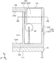
도 7은 본 실시의 형태와 관련되는 먼지 억제벽(30)의 구조를 나타내는 단면도이고, 구체적으로는, 도 3의 (a)에 나타내는 Ⅶ-Ⅶ선에 있어서의 단면을 나타내고 있다. 도 8은 본 실시의 형태와 관련되는 먼지 억제벽(30) 및 광 트랩(제 2 광 트랩)(40)의 구조를 나타내는 단면도이고, 구체적으로는, 도 7에 나타내는 Ⅷ-Ⅷ선에 있어서의 단면을 나타내고 있다.Fig. 7 is a cross-sectional view showing the structure of the
먼지 억제벽(30)은, 도 4에 나타내는 바와 같이, 하우징(10)의 내부에 있어서, 가열 장치(60)보다 유입구(101)에 가까운 위치에 마련되어 있다. 구체적으로는, 먼지 억제벽(30)의 적어도 일부는, 유입구(101)의 테두리를 따라 마련되어 있다. 본 실시의 형태에서는, 유입구(101)는 대략 직사각형의 개구이고, 먼지 억제벽(30)의 적어도 일부는, 해당 개구를 따라 마련되어 있다.The
또한, 먼지 억제벽(30)의 적어도 일부는, 가열 장치(60)가 생성하는 기류에 교차하는 방향과 평행하게 마련되어 있다. 가열 장치(60)는 기체를 가열함으로써 상승 기류를 생성하므로, 먼지 억제벽(30)의 적어도 일부는, 상승 기류에 직교하는 방향(즉, 수평 방향)에 평행하게 마련되어 있다.At least a part of the
또한, 먼지 억제벽(30)은, 유입구(101)의 폭보다 길다. 여기서, 유입구(101)의 폭은, 기체가 흐르는 방향에 교차하는 방향에 있어서의 폭이다. 구체적으로는, 유입구(101)의 폭은, 가열 장치(60)에 의해 생성되는 상승 기류에 교차하는 방향에 있어서의 폭이고, 예컨대, 수평 방향(X축 방향)에 있어서의 폭이다. 이것에 의해, 유입구(101)로부터 진입하는 외광이 검지 영역 DA를 조사하는 것을 억제할 수 있다. 또, 먼지 억제벽(30)은, 차광성을 갖는다.Further, the
또한, 먼지 억제벽(30)은, 광 트랩(40)의 폭보다 길다. 이것에 의해, 먼지 억제벽(30)은, 기체가 광 트랩(40)에 진입하는 것을 억제할 수 있다. 광 트랩(40)의 폭은, 먼지 억제벽(30)의 주면에 평행한 방향에 있어서, 광 트랩(40)의 개구로부터 안쪽까지의 거리이다. 예컨대, 광 트랩(40)의 폭은, 좌측면부(10e)와 광 반사벽(112)의 선단의 거리이다.Further, the
본 실시의 형태에서는, 먼지 억제벽(30)은, 내면(100a)으로부터 세워진 벽(103)과, 내면(110a)으로부터 세워진 벽(111)을 갖는다. 벽(103)과 벽(111)은, 도 7에 나타내는 바와 같이, 서로 포개져 있다. 바람직하게는, 벽(103)과 벽(111)은, 서로 접하고 있다. 구체적으로는, 벽(103) 및 벽(111)은, 정면에서 본 경우(Y축 방향으로 본 경우)에, 포개져 있다. 바람직하게는, 벽(103)과 벽(111)은, XZ면에서 서로 접하고 있다. 또, 내면(100a) 및 내면(110a)은, 하우징(10)이 갖는 내면으로서, 서로 대향하는 2개의 내면이다. 구체적으로는, 내면(100a)은, 전면부(10a)의 안쪽의 면이고, 내면(110a)은, 배면부(10b)의 안쪽의 면이다.In this embodiment, the
벽(103)은, 도 8에 나타내는 바와 같이, 유입구(101)의 테두리를 따라 마련되어 있다. 본 실시의 형태에서는, 유입구(101)는 대략 직사각의 개구이므로, 벽(103)은, L자 형상을 갖는다. 구체적으로는, 벽(103)은, 평판 형상의 장변부(103a)와, 평판 형상의 단변부(103b)를 갖는다.The
장변부(103a)는, 하면부(10c)에 평행하게 마련되어 있다. 또한, 장변부(103a)는, 좌측면부(10e)로부터 수직으로 세워져 있다. 단변부(103b)는, 좌측면부(10e)에 평행하게 마련되어 있다. 또한, 단변부(103b)는, 하면부(10c)로부터 수직으로 세워져 있다. 장변부(103a) 및 단변부(103b)의 높이(Z축 방향의 길이)는, 도 7에 나타내는 바와 같이, 전면 커버(100)의 측주부(하면부(10c)의 일부)보다 짧다.The
벽(111)은, 도 8에 나타내는 바와 같이, 유입구(101)의 근방에 마련되어 있다. 구체적으로는, 벽(111)은, 벽(103)의 장변부(103a)를 따라 마련되어 있고, 직선 형상을 갖는다. 본 실시의 형태에서는, 벽(111)은, 배면부(10b)(내면(110a)) 및 좌측면부(10e)의 각각으로부터 수직으로 세워진 평판 형상의 벽이다. 바꾸어 말하면, 벽(111)은, X축 방향에 있어서, 한쪽의 단부는 좌측면부(10e)에 접속되고, 다른 쪽의 단부는, 하우징(10)의 어느 내면에도 접속되어 있지 않다.The
이때, 벽(111)은, 도 4에 나타내는 바와 같이, 유입구(101)의 폭보다 길다. 구체적으로는, 벽(111)은, 도 8에 나타내는 바와 같이, 장변부(103a)의 폭보다 길다.At this time, the
먼지 억제벽(30)은, 하우징(10)의 서로 대향하는 2개의 내면을 접속하고 있다. 도 7에 나타내는 바와 같이, 벽(103)과 벽(111)이 서로 포개짐으로써, 내면(100a)과 내면(110a)을 접속하고 있다. 구체적으로는, 벽(103) 및 벽(111)은, 정면에서 본 경우(Y축 방향으로 본 경우)에, 내면(100a)과의 사이, 및, 내면(110a)과의 사이의 각각에 극간이 형성되지 않도록 마련되어 있다.The
본 실시의 형태에서는, 전면 커버(100)와 배면 커버(110)를 조합했을 때에, 벽(111)이 세워진 방향(Z축 방향)에 있어서의 선단이 전면 커버(100)의 내면(100a)에 닿아, 극간이 형성되지 않도록 설계되어 있다. 그렇지만, 극간을 완전하게 없애는 것은 어렵다.When the
이것에 대하여, 전면 커버(100)의 내면(100a)으로부터 세워진 벽(103)과 배면 커버(110)의 내면(110a)으로부터 세워진 벽(111)이 포개짐으로써, 벽(103) 및 벽(111)을 정면에서 보았을 때에 극간을 없앨 수 있다. 이것에 의해, 먼지 억제벽(30)은, 먼지 및 외광이 검지 영역 DA에 진입하는 것을 억제할 수 있다.The
[광 트랩(제 2 광 트랩)][Optical trap (second optical trap)]
광 트랩(40)은, 도 4에 나타내는 바와 같이, 복수의 폐공간(41, 43)과, 복수의 개구부(42, 44)와, 광 반사벽(112)과, 먼지 억제벽(30)을 갖는다. 광 트랩(40)은, 투광계(120)로부터 출력되어 검지 영역 DA를 통과한 광을, 광 반사벽(112)에서 분할한다.4, the
여기서, 복수의 개구부(42, 44)는, 제 2 개구부의 일례이고, 검지 영역 DA를 향해 개구하고 있고, 투광계(120)로부터 출력된 광이 직접 통과한다. 구체적으로는, 투광계(120)로부터 출력되어 검지 영역 DA를 통과한 후에 확산된 광의 대략 전부는, 하우징(10)의 내면 및 내부 구조 등에 반사되는 일 없이, 개구부(42, 44)를 통과한다. 개구부(42)에는, 광축 P가 통과하고 있다.Here, the plurality of
폐공간(41)은, 제 2 폐공간의 일례이고, 하우징(10)의 내부에 마련된, 미광을 흡수하기 위한 닫힌 공간이다. 폐공간(41)에는, 미광이 입사되기 위한 개구부(42)가 마련되어 있다. 또, 도 8에 나타내는 바와 같이, 광 반사벽(112)(구체적으로는, 반사부(112a))의 단부와 수광계 유지부(105, 117)의 사이가 개구부(42)에 상당한다.The
개구부(42)를 통해서, 폐공간(41)과 검지 영역 DA는 연통하고 있다. 다시 말해, 검지 영역 DA를 통과한 광의 일부는, 개구부(42)를 통해서 폐공간(41)에 진입한다. 진입한 광은, 폐공간(41) 내에서 다중 반사함으로써, 벽면에 흡수되어 감쇠한다.The
본 실시의 형태에서는, 폐공간(41)은, 도 8에 나타내는 바와 같이, 광 반사벽(112)과, 좌측면부(10e)와, 수광계 유지부(105, 117)와, 전면부(10a)(내면(100a))와, 배면부(10b)(내면(110a))에 의해 둘러싸인 공간이다. 폐공간(41)의 안쪽 부분은, 쐐기 형상을 갖는다.8, the
또, 쐐기형이란, 구체적으로는 V자 형상이고, 소정의 방향으로 보았을 때의 형상이 삼각형이 되는 형상이다. 쐐기형의 폐공간(및 후술하는 쐐기형 돌출부)은, 예컨대, 삼각뿔 형상 또는 삼각기둥 형상의 공간(및 돌출부)이다.In addition, the wedge shape is a shape that is V-shaped in detail and has a triangular shape when viewed in a predetermined direction. The wedge-shaped closed space (and a wedge-shaped protrusion to be described later) is, for example, a triangular-pyramidal or triangular-columnar space (and protruding portion).
본 실시의 형태에서는, 폐공간(41)의 안쪽 부분은, 전면부(10a) 및 배면부(10b)가 저면 및 상면을 형성하고, 좌측면부(10e)와 수광계 유지부(105, 117)가 2개의 측면을 형성하는 삼각기둥 형상의 공간이다. 다시 말해, 좌측면부(10e)와 수광계 유지부(105, 117)의 접속 부분이, 폐공간(41)의 가장 안쪽이고, 쐐기형의 선단에 상당한다.The
또, 나머지의 측면은, 쐐기형의 저변에 상당하는 면이고, 쐐기형의 선단보다 개구부(42)에 가까운 위치에 위치하고 있다. 개구부(42)를 통과한 광은, 해당 나머지의 측면을 통과하여 쐐기형의 선단 방향으로 진행한다.The other side surface is a surface corresponding to the base of the wedge-shaped portion, and is positioned closer to the opening
폐공간(43)은, 제 2 폐공간의 일례이고, 하우징(10)의 내부에 마련된, 미광을 흡수하기 위한 닫힌 공간이다. 폐공간(43)에는, 미광이 입사되기 위한 개구부(44)가 마련되어 있다. 또, 도 8에 나타내는 바와 같이, 광 반사벽(112)(구체적으로는, 반사부(112a))의 단부와 먼지 억제벽(30)(벽(111))의 단부의 사이가 개구부(44)에 상당한다.The
개구부(44)를 통해서, 폐공간(43)과 검지 영역 DA는 연통하고 있다. 다시 말해, 검지 영역 DA를 통과한 광의 일부는, 개구부(44)를 통해서 폐공간(43)에 진입한다. 입사된 광은, 폐공간(43) 내에서 다중 반사함으로써, 벽면에 흡수되어 감쇠한다.The
본 실시의 형태에서는, 폐공간(43)은, 도 8에 나타내는 바와 같이, 광 반사벽(112)과, 좌측면부(10e)와, 먼지 억제벽(30)(벽(111))과, 전면부(10a)(내면(100a))와, 배면부(10b)(내면(110a))에 의해 둘러싸인 공간이다. 폐공간(43)의 안쪽 부분은, 쐐기 형상을 갖는다.8, the closed
구체적으로는, 폐공간(43)의 안쪽 부분은, 전면부(10a) 및 배면부(10b)가 저면 및 상면을 형성하고, 좌측면부(10e) 및 반사부(112b)가 2개의 측면을 형성하는 삼각기둥 형상의 공간이다. 다시 말해, 좌측면부(10e)와 광 반사벽(112)의 접속 부분이, 폐공간(43)의 가장 안쪽이고, 쐐기형의 선단에 상당한다.More specifically, the inner portion of the closed
또, 나머지의 측면은, 쐐기형의 저변에 상당하는 면이고, 쐐기형의 선단보다 개구부(44)에 가까운 위치에 위치하고 있다. 개구부(42)를 통과한 광은, 해당 나머지의 측면을 통과하여 쐐기형의 선단 방향으로 진행한다.The other side surface is a surface corresponding to the base of the wedge-shaped body and is positioned closer to the
광 반사벽(112)은, 제 1 광 반사벽의 일례이고, 개구부(42)를 통과한 광을 반사함으로써, 해당 광을 폐공간(41)의 안쪽 부분으로 진행시킨다. 또한, 광 반사벽(112)은, 개구부(44)를 통과한 광을 반사함으로써, 해당 광을 폐공간(43)으로 진행시킨다.The
광 반사벽(112)은, 굴곡한 벽이다. 구체적으로는, 도 8에 나타내는 바와 같이, 광 반사벽(112)은, 평판 형상의 반사부(112a)와, 평판 형상의 반사부(112b)를 갖는다.The
반사부(112a)는, 제 1 반사부의 일례이고, 투광계(120)의 광축 P에 교차하도록 마련되어 있다. 구체적으로는, 반사부(112a)는, 투광계(120)로부터 출력된 광 중, 광축 P 상을 진행하는 광을 반사하고, 그 반사광이 반사부(112b)에서 더 반사되도록 배치되어 있다. 본 실시의 형태에서는, 반사부(112a)는, 하면부(10c)와 평행하게 배치되어 있다.The reflecting
반사부(112b)는, 제 2 반사부의 일례이고, 반사부(112a)에 대하여 경사하여 마련되어 있다. 구체적으로는, 반사부(112b)는, 광축 P 상을 진행하는 광의, 반사부(112a)에 의한 반사광을, 폐공간(41)의 쐐기형의 선단 방향을 향해 반사하도록 배치되어 있다.The reflecting
본 실시의 형태에서는, 반사부(112b)는, 반사부(112a) 및 좌측면부(10e)의 각각에 대하여 소정의 각도를 이루도록 배치되어 있다. 반사부(112b)와 좌측면부(10e)는, 예각을 이루고, 해당 예각이 폐공간(43)의 쐐기형의 선단에 상당한다.In the present embodiment, the reflecting
이상의 구성에 의해, 투광계(120)로부터 출력되어 검지 영역 DA를 통과한 광(출사광)의 일부는, 개구부(42)를 통과하고, 광 반사벽(112)(및, 좌측면부(10e), 수광계 유지부(105, 117))에 의해 반사되어 폐공간(41)으로 진행한다. 또한, 출사광의 다른 일부는, 개구부(44)를 통과하고, 먼지 억제벽(30)(및, 광 반사벽(112) 및 좌측면부(10e))에 의해 반사되어 폐공간(43)으로 진행한다. 폐공간(41, 43)으로 진행한 광은, 반사할 때에 벽면에 흡수되어 감쇠한다.A part of the light (emitted light) output from the
[광 트랩(제 1 광 트랩)][Optical trap (first optical trap)]
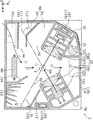
도 9는 본 실시의 형태와 관련되는 광 트랩(제 1 광 트랩)(50)의 구성을 나타내는 단면도이고, 구체적으로는, 도 4에 나타내는 단면의 확대도이다.Fig. 9 is a cross-sectional view showing a configuration of a light trap (first light trap) 50 according to the present embodiment, specifically, an enlarged view of a cross section shown in Fig.
광 트랩(50)은, 도 9에 나타내는 바와 같이, 폐공간(51)과, 개구부(52)와, 광 반사벽(113)과, 광 반사벽(114)과, 복수의 쐐기형 돌출부(115)를 갖는 미로 구조이다.9, the
폐공간(51)은, 제 1 폐공간의 일례이고, 하우징(10)의 내부에 마련된, 미광을 흡수하기 위한 닫힌 공간이다. 폐공간(51)에는, 검지 영역 DA를 향해 개구한 개구부(52)가 마련되어 있다. 개구부(52)는, 제 1 개구부의 일례이고, 수광계(130)의 광축 Q와 교차하고 있다. 도 9에 나타내는 바와 같이, 광 반사벽(113)의 단부와 광 반사벽(114)(구체적으로는, 반사부(114a))의 단부의 사이가 개구부(52)에 상당한다.The
구체적으로는, 폐공간(51)은, 도 9에 나타내는 바와 같이, 광 반사벽(113)과, 광 반사벽(114)과, 하면부(10c)와, 우측면부(10f)와, 전면부(10a)(내면(100a))와, 배면부(10b)(내면(110a))에 의해 둘러싸인 공간이다.9, the
개구부(52)를 통해서, 폐공간(51)과 검지 영역 DA는 연통하고 있다. 다시 말해, 폐공간(51)으로부터 개구부(52)를 통해서 광이 출사된 경우, 검지 영역 DA를 통과하여 수광계(130)에 도달할 가능성이 있다. 이 때문에, 광 트랩(50)은, 개구부(52)를 통해서 폐공간(51)에 진입한 광이, 다시 개구부(52)를 통해서 출사되지 않도록 형성되어 있다.The
광 반사벽(113)은, 제 2 광 반사벽의 일례이고, 복수의 쐐기형 돌출부(115)의 돌출 방향에 교차하고, 또한, 수광계(130)의 광축 Q와 대략 평행하게 배치되어 있다. 광 반사벽(1130)은, 예컨대 평판 형상의 벽이고, 배면부(10b)(내면(110a)) 및 우측면부(10f)의 각각으로부터 세워져 있다. 광 반사벽(113)은, 투광계(120)로부터 출력되어 하우징(10)의 내면에서 반사된 광을, 복수의 쐐기형 돌출부(115)를 향해 반사한다. 예컨대, 광 반사벽(113)은, 개구부(52)를 대략 수평 방향으로 통과하는 광을, 복수의 쐐기형 돌출부(115)를 향해 반사한다.The
광 반사벽(114)은, 투광계(120)로부터 출사되어 광 트랩(40)에 트랩되지 않은 광(미광)을 반사한다. 광 반사벽(114)은, 소정의 방향(Y축 방향)에 있어서의 한쪽의 단부가 하면부(10c)에 접속되고, 다른 쪽의 단부가 하우징(10)의 어느 내면에도 접속되어 있지 않다. 해당 다른 쪽의 단부가 검지 영역 DA를 향하도록, 광 반사벽(114)은 마련되어 있다. 본 실시의 형태에서는, 광 반사벽(114)은, 굴곡한 벽이다. 구체적으로는, 도 9에 나타내는 바와 같이, 광 반사벽(114)은, 평판 형상의 반사부(114a)와, 평판 형상의 반사부(114b)를 갖는다.The
반사부(114a)는, 그 벽면의 연장선 상에 검지 영역 DA가 위치하도록 배치되어 있다. 반사부(114a)는, 예컨대, 개구부(52)를 통과한 미광을 폐공간(51)측의 면에서 반사하고, 반사부(114a)와 쐐기형 돌출부(115a)의 사이의 공간에서 흡수한다. 또한, 반사부(114a)는, 예컨대, 가열 장치(60)측의 면에서, 하면부(10c)에서 반사된 광을 광 트랩(40)을 향해 반사한다.The reflecting
반사부(114b)는, 배면부(10b)(내면(110a)) 및 하면부(10c)의 각각에 수직으로 세워져 있다. 반사부(114b)는, 예컨대, 하면부(10c)에서 반사된 광을 광 트랩(40)을 향해 반사한다.The reflecting
또한, 광 반사벽(114)은, 먼지 억제벽(30)(기체 유도벽)에 의해 유도된 기체를 검지 영역 DA를 향해 유도하는 기체 유도벽이다. 또한, 광 반사벽(114)은, 유입구(101)와 광 트랩(50)의 사이에 마련된 벽이고, 먼지 억제벽(30)에 의해 유도된 기체가 광 트랩(50)에 진입하지 않도록 유도한다. 이때, 반사부(114a)가 검지 영역 DA를 향하도록 배치되어 있으므로, 기체를 검지 영역 DA를 향해 효율적으로 유도할 수 있다.The
복수의 쐐기형 돌출부(115)는, 폐공간(51)에 마련되고, 하우징(10)의 측면으로부터 안쪽을 향해 돌출한 쐐기형의 벽이다. 복수의 쐐기형 돌출부(115)는, 폐공간(51) 내에 있어서, 배면 커버(110)의 내면(110a)으로부터 세워져 있다.The plurality of wedge-shaped
본 실시의 형태에서는, 도 9에 나타내는 바와 같이, 하면부(10c)로부터 소정의 방향으로 돌출하도록, 6개의 쐐기형 돌출부(115a~115f)가 마련되어 있다. 6개의 쐐기형 돌출부(115a~115f)의 각각의 돌출 방향은, 수광계(130)의 광축 Q에 교차하고 있다. 또, 도 9에서는, 쐐기형 돌출부의 돌출 방향을 일점쇄선으로 나타내고 있다. 돌출 방향은, 예컨대, 쐐기형(삼각형)의 선단으로부터 저변(하면부(10c))으로의 중선의 방향이다.In this embodiment, as shown in Fig. 9, six wedge-shaped
6개의 쐐기형 돌출부(115a~115f)는, 검지 영역 DA로부터 멀수록, 검지 영역 DA로부터 멀어지는 방향으로 돌출하고 있다. 예컨대, 도 9에 나타내는 바와 같이, 6개의 쐐기형 돌출부(115a~115f)는, 이 순서로 검지 영역 DA(또는, 개구부(52))로부터의 거리가 커지도록 배치되어 있다. 이때, 쐐기형 돌출부(115a, 115b)의 돌출 방향은, 하면부(10c)에 대략 수직인 방향인 것에 비하여, 쐐기형 돌출부(115c~115f)는, 각각의 돌출 방향과 하면부(10c)가 이루는 각도 θ1~θ6이, 차례로 작아지고 있다. 각도 θ1~θ6은, θ1≥θ2≥θ3≥θ4≥θ5≥θ6의 관계를 만족시키고 있다.The six wedge-shaped
본 실시의 형태에서는, 복수의 쐐기형 돌출부(115a~115f)의 각각은, 위쪽을 향해 돌출하고 있다. 예컨대, 쐐기형 돌출부(115a, 115b)는, 대략 연직 위쪽을 향해 돌출하고 있다. 쐐기형 돌출부(115c~115f)는, 비스듬하게 위쪽을 향해 돌출하고 있다.In the present embodiment, each of the plurality of wedge-shaped
또한, 6개의 쐐기형 돌출부(115a~115f)는, 검지 영역 DA로부터 멀수록, 쐐기형의 선단과 저변의 거리 h1~h6이 짧아진다. 본 실시의 형태에서는, 6개의 쐐기형 돌출부(115a~115f)의 각각의 저변은, 하면부(10c)에 상당한다. 따라서, 거리 h1~h6은 각각, 쐐기형 돌출부(115a~115f)의 각각의 선단과 하면부(10c)의 거리이다. 도 9에 나타내는 바와 같이, 거리 h1~h6은, h1≥h2≥h3≥h4≥h5≥h6의 관계를 만족시키고 있다.The distances h1 to h6 between the tips of the wedge-shaped
[효과 등][Effects, etc.]
본 실시의 형태와 관련되는 입자 검출 센서(1)는, 다양한 기기에 적용하기 위해 소형화되어 있다. 이하에서는, 우선, 입자 검출 센서(1)를 소형화한 경우에 생기는 문제에 대하여, 도 10을 이용하여 설명한다.The
도 10은 본 실시의 형태와 관련되는 입자 검출 센서(1)의 투광계(120)로부터 출사되는 광의 경로를 나타내는 도면이다.10 is a diagram showing the path of light emitted from the light projecting
하우징(10)이 소형화되면, 투광계(120)와 검지 영역 DA의 거리가 짧아진다. 이 때문에, 투광 렌즈(122)는, 초점 거리가 짧은 렌즈가 필요하게 된다. 초점 거리가 짧은 렌즈에 의해 강하게 집속된 광은, 큰 확산각을 갖고 확산된다. 구체적으로는, 도 10에 나타내는 바와 같이, 검지 영역 DA를 통과할 때에 입자(2)에 의해 산란되지 않은 광은, 큰 확산각을 갖고 확산된다. 또, 도 10에서는, 투광계(120)로부터 출사된 광이 통과하는 영역을 도트의 해칭으로 나타내고 있다.When the
입자(2)에 의한 산란광 이외의 광(구체적으로는, 미광)은, 노이즈의 요인이 되기 때문에, 수광계(130)에 입사되지 않도록 하우징(10) 내에서 흡수시키는 것이 요구된다. 그렇지만, 도 10에 나타내는 바와 같이, 검지 영역 DA를 통과한 후에 크게 확산된 미광을 흡수하는 것은 어렵다.The light other than the scattered light by the particle 2 (specifically stray light) is required to be absorbed in the
이것에 대하여, 본 실시의 형태와 관련되는 입자 검출 센서(1)는, 검지 영역 DA에 집광하도록 광을 출력하는 투광계(120)와, 검지 영역 DA에 있어서의 입자(2)에 의한 투광계(120)로부터의 광의 산란광을 수광하는 수광계(130)와, 검지 영역 DA를 사이에 두고 투광계(120)와 대향하는 위치에 마련된 광 트랩(40)을 구비하고, 광 트랩(40)은, 복수의 개구부(42, 44)를 갖고, 투광계(120)로부터 출력되어 검지 영역 DA를 통과한 광을, 복수의 개구부(42, 44)의 각각을 통과하도록 분할하고 나서 트랩한다.On the contrary, the
이와 같이, 검지 영역 DA를 통과하여 크게 확산된 미광은, 도 10의 흰색의 화살표로 나타내는 바와 같이, 광 반사벽(112)에 의해 분할된다. 분할된 광은 각각, 개구부(42, 44)를 통과하여, 폐공간(41, 43)으로 진행하고, 다중 반사되어 흡수된다. 이것에 의해, 크게 확산된 미광을 복수의 개구부(42, 44)의 각각을 통과하도록 분할함으로써, 효율적으로 트랩할 수 있다.As described above, the stray light greatly diffused through the detection area DA is divided by the
예컨대, 미광을 분할하여 트랩함으로써, 미광을 트랩하기 위한 폐공간의 설계의 자유도가 높아진다. 예컨대, 다양한 방향으로 진행하는 미광을 1개의 폐공간에서 트랩하기 위해서는, 복잡한 구조가 필요하게 되는 것에 비하여, 미광을 분할하여 복수의 폐공간에서 트랩함으로써, 복수의 폐공간의 각각의 구성을 간이하게, 또한, 적합한 형상으로 설계할 수 있다. 이것에 의해, 간이한 구성으로 효과적으로 미광을 트랩할 수 있다.For example, by dividing and trapping the stray light, the degree of freedom in designing the closed space for trapping stray light is increased. For example, in order to trap stray light traveling in various directions in one closed space, a complicated structure is required. In contrast to this, stray light is divided and trapped in a plurality of closed spaces, , And can be designed in a suitable shape. As a result, the stray light can be trapped effectively with a simple configuration.
이하에서는, 본 실시의 형태와 관련되는 입자 검출 센서(1)가 미광을 효율적으로 트랩할 수 있는 것을, 미광의 예를 들면서, 도 11~도 13을 이용하여 설명한다.Hereinafter, the
도 11 및 도 12는 본 실시의 형태와 관련되는 광 트랩(40)에 트랩되는 광의 경로를 나타내는 도면이다. 구체적으로는, 도 11은 분할된 광 중, 개구부(42)를 통과한 광을 폐공간(41)에서 트랩하는 경우를 나타내고 있다. 도 12는 분할된 광 중, 개구부(44)를 통과한 광을 폐공간(43)에서 트랩하는 경우를 나타내고 있다.Figs. 11 and 12 are views showing paths of light trapped in the
예컨대, 투광계(120)의 광축 P 상을 진행하는 광은, 도 11의 굵은 실선의 화살표로 나타내는 바와 같이, 광 반사벽(112)에 의해 반사된다. 구체적으로는, 우선, 반사부(112a)에 의해 반사된 후, 반사부(112b)에 의해 더 반사된다. 다시 말해, 광 반사벽(112)은, 광축 P 상을 진행하는 광을 적어도 2회 반사할 수 있도록 배치되어 있다.For example, light traveling on the optical axis P of the light projecting
반사부(112b)에 의해 반사된 광은, 좌측면부(10e)에 의해 반사되고, 또한, 수광계 유지부(117)(및 수광계 유지부(105))에 의해 반사된다. 이와 같이, 개구부(42)를 통과한 광은, 폐공간(41) 내에서 다중 반사되어, 폐공간(41)의 안쪽 부분(쐐기형의 선단 방향)으로 진행한다. 광은, 반사될 때마다 벽면에 흡수되어 감쇠하므로, 최종적으로, 해당 광을 벽면에서 대략 완전하게 흡수할 수 있다.The light reflected by the reflecting
이때, 광축 P 상을 진행하는 광은, 특히 광 에너지가 강하다. 따라서, 광축 P 상을 진행하는 광을 다중 반사시킴으로써, 효율적으로 광을 흡수시킬 수 있다. 광축 P 상을 진행하는 광이, 폐공간(41)으로부터 검지 영역 DA 쪽으로 다시 출사되지 않도록 함으로써, 입자의 검출 정밀도를 높일 수 있다.At this time, the light traveling on the optical axis P is particularly strong in light energy. Therefore, by multiply reflecting light traveling on the optical axis P, it is possible to efficiently absorb light. It is possible to increase the detection accuracy of the particles by preventing light traveling on the optical axis P from being emitted again from the closed
또한, 도 12의 굵은 실선의 화살표로 나타내는 바와 같이, 개구부(44)를 통과한 광은, 벽(111)에 의해 반사된다. 이후, 반사부(112a), 먼지 억제벽(30), 좌측면부(10e)의 차례로 반사되어 폐공간(43)의 안쪽 부분(쐐기형의 선단 방향)으로 진행한다.12, the light passing through the opening
이것에 의해, 개구부(44)를 통과한 광은, 반사될 때마다 벽면에 흡수되어 감쇠하므로, 최종적으로, 해당 광을 벽면에서 대략 완전하게 흡수할 수 있다.As a result, the light passing through the
이상과 같이, 예컨대, 본 실시의 형태와 관련되는 입자 검출 센서(1)에서는, 광 트랩(40)은, 복수의 개구부 중 하나의 개구부(42)가 마련된 폐공간(41)과, 개구부(42)를 통과한 광을 반사함으로써, 해당 광을 폐공간(41)의 안쪽 부분으로 진행시키는, 굴곡한 광 반사벽(112)을 더 갖는다. 또한, 예컨대, 광 반사벽(112)은, 투광계(120)의 광축 P에 교차하도록 마련된 평판 형상의 반사부(112a)와, 반사부(112a)에 대하여 경사하여 마련된 평판 형상의 반사부(112b)를 갖고, 투광계(120)로부터 출력된 광 중, 투광계(120)의 광축 P 상을 진행하는 광은, 반사부(112a)와 반사부(112b)에 의해, 이 차례로 반사되어 폐공간(41)의 안쪽 부분으로 진행한다.As described above, for example, in the
이것에 의해, 굴곡한 광 반사벽(112)에 의해 미광을 효율적으로 폐공간(41)으로 진행시킬 수 있다. 특히, 광 에너지가 강한 광축 P 상을 진행하는 광을 폐공간(41)으로 진행시킬 수 있고, 반사를 반복함으로써, 효율적으로 감쇠시킬 수 있다. 따라서, 수광계(130)에 입사하는 미광을 줄일 수 있으므로, 입자 검출의 S/N 비를 향상시킬 수 있다. 이와 같이, 입자의 검출 정밀도를 향상시킬 수 있다.As a result, the stray light can be efficiently advanced to the closed
또한, 예컨대, 폐공간(41)의 안쪽 부분은, 쐐기 형상을 갖는다.Further, for example, the inner portion of the closed
이것에 의해, 광은, 쐐기형의 안쪽 부분으로 향할수록, 몇 번이나 다중 반사되므로, 광을 효율적으로 감쇠시킬 수 있다.As a result, the light is reflected multiple times as many times as it goes toward the inner portion of the wedge shape, so that light can be efficiently attenuated.
또한, 예컨대, 광 트랩(40)은, 광 반사벽(112)에 의해, 투광계(120)로부터 출력되어 검지 영역 DA를 통과한 광을 분할한다.Further, for example, the
이것에 의해, 광을 분할하는 기능과, 분할한 광을 반사하는 기능을 1개의 벽에 의해 실현할 수 있으므로, 하우징(10)의 내부를 간이한 구성으로 할 수 있다. 따라서, 하우징(10)의 내부에서 불필요한 광의 반사 등이 일어나기 어려워지고, 미광이 수광계(130)에 조사되는 것을 억제할 수 있다. 따라서, 입자의 검출 정밀도를 향상시킬 수 있다.As a result, the function of dividing the light and the function of reflecting the divided light can be realized by one wall, so that the inside of the
또한, 한편으로, 도 11의 굵은 파선의 화살표로 나타내는 바와 같이, 투광계(120)로부터 출사된 광 중, 개구부(42) 및 개구부(44)를 통과하지 않고, 반사부(112a)의 단부에 의해 반사되는 광도 존재한다. 해당 광은, 도 11에 나타내는 바와 같이, 하면부(10c) 및 광 반사벽(114)에 의해 차례로 반사되고, 개구부(42)를 통과하여 폐공간(41)으로 진행한다.On the other hand, as shown by the thick broken-line arrows in Fig. 11, the light emitted from the light projecting
이와 같이, 광 반사벽(114)은, 개구부(42) 및 개구부(44)를 통과하지 않은 광을 반사함으로써, 해당 광을 광 트랩(40)으로 진행시킬 수 있다. 이것에 의해, 수광계(130)에 입사하는 미광을 줄일 수 있으므로, S/N 비를 향상시킬 수 있다.As described above, the
상술한 바와 같이, 대부분의 미광은 광 트랩(40)에 의해 트랩된다. 그렇지만, 일부의 미광은, 광 트랩(40)에 일단 입사하였지만, 다시 출사된다. 혹은, 광 트랩(40)에 입사하지 않는 미광도 존재한다. 광 트랩(50)은, 이들 광(누설광)을 트랩한다.Most of the stray light is trapped by the
도 13은 본 실시의 형태와 관련되는 광 트랩(50)에 트랩되는 광의 경로를 나타내는 도면이다.13 is a view showing the path of light trapped in the
도 13의 굵은 실선의 화살표로 나타내는 바와 같이, 투광 렌즈(122)의 가장 바깥쪽을 통과하여 투광계(120)로부터 출사된 광은, 대략 수평으로 진행하고, 개구부(42)를 통과하여 광 트랩(40)에 입사하지만, 좌측면부(10e)에 의해 반사되어, 다시 개구부(42)로부터 출사된다. 해당 광은, 광 트랩(50)의 개구부(52)를 통과하고, 광 반사벽(113)에 의해 복수의 쐐기형 돌출부(115)를 향해 반사된다. 그리고, 이웃하는 쐐기형 돌출부(115)의 사이에서 다중 반사되어 흡수된다.The light that has passed through the outermost side of the
또한, 도 13의 굵은 파선의 화살표로 나타내는 바와 같이, 투광계(120)로부터 대략 직하로 출사된 광은, 검지 영역 DA를 통과하는 일 없이, 직접 개구부(52)를 통과하여 광 반사벽(114)에 반사된다. 해당 광은, 반사부(114a)와 쐐기형 돌출부(115)의 사이에서 다중 반사되어 흡수된다.13, the light emitted substantially straight from the
이상과 같이, 예컨대, 본 실시의 형태와 관련되는 입자 검출 센서(1)는, 검지 영역 DA를 사이에 두고 수광계(130)와 대향하는 위치에 마련되어, 광 트랩(40)에 트랩되지 않는 광을 트랩하는 광 트랩(50)을 더 구비하고, 광 트랩(50)은, 검지 영역 DA를 향해 개구한 개구부(52)가 마련된 폐공간(51)과, 폐공간(51)에 마련된 복수의 쐐기형 돌출부(115)를 갖는다.As described above, for example, the
이것에 의해, 광 트랩(50)에 의해, 광 트랩(40)으로부터 출사된 광, 및, 광 트랩(40)에 입사되지 않은 광 등의 누설광을 트랩할 수 있다. 따라서, 수광계(130)에 입사하는 누설광을 감소시켜, S/N 비를 향상시킬 수 있고, 입자의 검출 정밀도를 더 향상시킬 수 있다.Thereby, the
또한, 예컨대, 광 트랩(50)은, 복수의 쐐기형 돌출부(115)의 돌출 방향에 교차하고, 또한, 수광계(130)의 광축 Q와 대략 평행하게 배치된 광 반사벽(113)을 더 갖는다.Further, for example, the
이것에 의해, 광 반사벽(113)에 의해 복수의 쐐기형 돌출부(115)를 향해 반사할 수 있다. 예컨대, 광 반사벽(113)은, 하우징(10) 내를 대략 수평 방향으로 진행하는 누설광을 반사할 수 있다. 따라서, 수광계(130)에 입사하는 누설광을 감소시켜, S/N 비를 향상시킬 수 있고, 입자의 검출 정밀도를 더 향상시킬 수 있다.Thus, the
또한, 예컨대, 복수의 쐐기형 돌출부(115)의 각각의 돌출 방향은, 수광계(130)의 광축 Q에 교차하고 있다.In addition, for example, the projecting directions of each of the plurality of wedge-shaped
이것에 의해, 광 반사벽(113)에 의해 반사된 광이, 이웃하는 쐐기형 돌출부(115)의 사이로 진행하기 쉬워진다. 바꾸어 말하면, 해당 광은, 이웃하는 쐐기형 돌출부(115)의 사이에서 다중 반사되기 쉬워진다. 따라서, 수광계(130)에 입사하는 누설광을 감소시켜, S/N 비를 향상시킬 수 있고, 입자의 검출 정밀도를 더 향상시킬 수 있다.As a result, the light reflected by the
또한, 예컨대, 복수의 쐐기형 돌출부(115)는, 검지 영역 DA로부터 멀수록, 쐐기형의 선단과 저변의 거리가 짧다.Further, for example, the distance between the tip of the wedge-shaped
이것에 의해, 쐐기형 돌출부(115)의 선단에서 반사된 광이 수광계(130)로 향하는 것을 억제할 수 있다. 예컨대, 가장 짧은 쐐기형 돌출부(115f)의 선단에서 광이 수광계(130)를 향해 반사된 경우, 근처의 쐐기형 돌출부(115e)에 의해 다시 반사된다. 따라서, 수광계(130)에 입사하는 누설광을 감소시켜, S/N 비를 향상시킬 수 있고, 입자의 검출 정밀도를 더 향상시킬 수 있다.As a result, the light reflected by the tip of the wedge-shaped
또한, 예컨대, 복수의 쐐기형 돌출부(115)는, 검지 영역 DA로부터 멀수록, 검지 영역 DA로부터 멀어지는 방향으로 돌출하고 있다.In addition, for example, the plurality of wedge-shaped
이것에 의해, 광 반사벽(113)에 의해 반사된 광이, 이웃하는 쐐기형 돌출부(115)의 사이로 진행하기 쉬워진다. 바꾸어 말하면, 해당 광은, 이웃하는 쐐기형 돌출부(115)의 사이에서 다중 반사되기 쉬워진다. 따라서, 수광계(130)에 입사하는 누설광을 감소시켜, S/N 비를 향상시킬 수 있고, 입자의 검출 정밀도를 더 향상시킬 수 있다.As a result, the light reflected by the
또한, 예컨대, 복수의 쐐기형 돌출부(115)의 각각은, 위쪽을 향해 돌출하고 있다.In addition, for example, each of the plurality of wedge-shaped
이것에 의해, 광 트랩(50) 내에 먼지가 침입한 경우, 먼지는 복수의 쐐기형 돌출부(115)의 사이에 퇴적된다. 이 때문에, 미광이 광 트랩(50) 내에 침입하여 먼지에 의해 확산 반사되었다고 하더라도, 그 반사광은, 이웃하는 쐐기형 돌출부(115)의 사이에서 다중 반사되기 쉽다. 다중 반사에 의해 반사광이 감쇠하므로, 반사광이 광 트랩(50)으로부터 수광계(130)를 향해 출사되는 것을 억제할 수 있다. 또, 이것은, 광 트랩(50)에 입사하는 미광을 복수의 쐐기형 돌출부(115)에 의해 트랩하는 원리를, 반대로 응용할 수 있는 것을 의미하고 있다.Thus, when dust enters the
이와 같이, 복수의 쐐기형 돌출부(115)의 사이에 먼지가 퇴적되었다고 하더라도, 복수의 쐐기형 돌출부(115)가 마련되어 있지 않은 경우에 비하여, 먼지에 의한 반사광이 수광계(130)에 입사하는 것을 억제할 수 있다. 따라서, 입자 검출 센서(1)에 의한 입자의 검출 정밀도를 한층 향상시킬 수 있다.As described above, even when dust is deposited between the plurality of wedge-shaped
(변형예)(Modified example)
계속하여, 상기 실시의 형태와 관련되는 입자 검출 센서(1)의 변형예에 대하여, 도 14를 이용하여 설명한다. 이하에서는, 상기 실시의 형태와 상이한 점을 중심으로 설명하고, 동일한 점에 대해서는 설명을 생략 또는 간략화한다.Next, modified examples of the
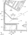
도 14는 본 변형예와 관련되는 입자 검출 센서(1A)의 하우징 내부를 나타내는 단면도이다. 도 14에 나타내는 단면은, 도 4와 마찬가지로, 도 3의 (c)의 Ⅳ-Ⅳ선에 있어서의 단면에 상당한다.14 is a sectional view showing the inside of the housing of the
본 변형예와 관련되는 입자 검출 센서(1A)는, 도 4에 나타내는 입자 검출 센서(1)와 비교하여, 광 반사벽(112), 광 반사벽(113) 및 광 반사벽(114)을 구비하지 않는 점이 상이하다. 구체적으로는, 입자 검출 센서(1A)는, 광 트랩(40) 및 광 트랩(50) 대신에, 광 트랩(40A) 및 광 트랩(50A)을 구비한다.The
광 트랩(40A)은, 광 반사벽(112)을 구비하지 않는다. 구체적으로는, 광 트랩(40A)은, 1개만의 폐공간(41A)을 갖는다. 폐공간(41A)에는, 1개만의 개구부(42A)가 마련되어 있다. 폐공간(41A)은, 먼지 억제벽(30)(벽(111))과, 좌측면부(10e)와, 수광계 유지부(105, 117)와, 전면부(10a)(내면(100a))와, 배면부(10b)(내면(110a))에 의해 둘러싸인 공간이다. 먼지 억제벽(30)의 단부와 수광계 유지부(105, 117)의 단부의 사이가, 개구부(42A)에 상당한다.The light trap 40A does not have the
폐공간(41A)의 안쪽 부분, 즉, 좌측면부(10e)와 수광계 유지부(105, 117)의 접속 부분은, 쐐기 형상을 갖는다. 광이 쐐기형의 안쪽 부분으로 향할수록, 몇 번이나 다중 반사되므로, 미광을 효율적으로 감쇠시킬 수 있다.The inner portion of the closed space 41A, that is, the connecting portion between the left
광 트랩(50A)은, 광 반사벽(113) 및 광 반사벽(114)을 구비하지 않는다. 구체적으로는, 광 트랩(50A)은, 1개만의 폐공간(51A)을 갖는다. 폐공간(51A)에는, 1개만의 개구부(52A)가 마련되어 있다. 폐공간(51A)은, 하면부(10c)와, 우측면부(10f)와, 투광계 유지부(104, 116)와, 쐐기형 돌출부(115a)에 의해 둘러싸인 공간이다. 가장 검지 영역 DA 쪽에 위치하는 쐐기형 돌출부(115a)의 선단과 투광계 유지부(104, 116)의 단부의 사이가, 개구부(52A)에 상당한다.The
이상과 같이, 본 변형예와 관련되는 입자 검출 센서(1A)에 의하면, 복수의 쐐기형 돌출부(115)를 이용하여 미광을 효과적으로 트랩할 수 있다. 또, 상기 실시의 형태와 관련되는 입자 검출 센서(1) 쪽이 하우징 내부의 구조가 복잡하기 때문에, 미광의 트랩 효과가 높다. 이것에 비하여, 본 변형예와 관련되는 입자 검출 센서(1A)는, 입자 검출 센서(1)보다 트랩 효과는 낮지만, 충분히 높은 정밀도로 입자를 검출할 수 있다.As described above, according to the
예컨대, 본 변형예와 관련되는 입자 검출 센서(1A)에서는, 광 트랩(50A)에는 복수의 쐐기형 돌출부(115)가 마련되어 있다. 이 때문에, 광 반사벽(113) 및 광 반사벽(114)이 마련되어 있지 않더라도, 복수의 쐐기형 돌출부(115)의 사이에서 광이 다중 반사하므로, 미광을 충분히 감쇠시킬 수 있다.For example, in the
또한, 본 변형예에서는, 복수의 쐐기형 돌출부(115)는, 검지 영역 DA로부터 멀어질수록, 짧아지도록 형성되어 있다. 따라서, 광 반사벽(113, 114)이 마련되어 있지 않더라도, 광이 보다 안쪽의(즉, 검지 영역 DA로부터 보다 떨어진) 쐐기형 돌출부(115)의 사이에 입사되기 쉬워진다. 이 때문에, 미광이 광 트랩(50A)으로부터 수광계(130)로 향하여 빠져나오는 것을, 보다 한층 억제할 수 있다.In this modification, the plurality of wedge-shaped
또한, 본 변형예와 관련되는 입자 검출 센서(1A)에 의하면, 하우징(10)의 내부의 구조가 간소화되어 있으므로, 내부에 모인 먼지를 제거하는 등의 메인터넌스가 용이하게 된다. 또한, 하우징(10)을 형성하는데 사용하는 재료의 양을 삭감할 수 있으므로, 입자 검출 센서(1A)를 낮은 비용으로 제조할 수 있다.Further, according to the
(그 외)(etc)
이상, 본 발명과 관련되는 입자 검출 센서에 대하여, 상기 실시의 형태 및 그 변형예에 근거하여 설명했지만, 본 발명은, 상기의 실시의 형태로 한정되는 것이 아니다.The particle detection sensor according to the present invention has been described above based on the above-described embodiment and its modification, but the present invention is not limited to the above embodiment.
예컨대, 상기의 실시의 형태에서는, 먼지 억제벽(30)이 벽(103)과 벽(111)으로 구성되는 예에 대하여 나타냈지만, 이것에 한하지 않는다. 먼지 억제벽(30)은, 예컨대, 벽(103)만 또는 벽(111)만으로 구성되더라도 좋다.For example, in the above-described embodiment, the
또한, 예컨대, 상기의 실시의 형태에서는, 먼지 억제벽(30)이 유입구(101)의 테두리를 따라 하면부(10c)에 평행하게 마련되었지만, 이것에 한하지 않는다. 먼지 억제벽(30)은, 하면부(10c)에 대하여 경사하여 마련되더라도 좋다. 예컨대, 먼지 억제벽(30)은, 유입구(101)와 검지 영역 DA를 잇는 선에 직교하도록 마련되더라도 좋다. 또한, 먼지 억제벽(30)은, 평판이 아닌, 만곡한 판이더라도 좋다.For example, in the above-described embodiment, the
또한, 예컨대, 먼지 억제벽(30)은, 가열 장치(60)와 검지 영역 DA의 사이에 마련되더라도 좋다.Further, for example, the
또한, 예컨대, 상기의 실시의 형태에서는, 2개의 개구부(42, 44)에 의해 검지 영역 DA를 통과한 광을 분할하는 예에 대하여 설명했지만, 이것에 한하지 않는다. 개구부는 3개 이상이더라도 좋다. 예컨대, 광 트랩(40)으로서, 복수의 평행 평판 형상의 광 트랩 구조를 이용하더라도 좋다. 다시 말해, 복수의 평행 평판의 각각의 사이가, 복수의 개구부에 상당한다. 평행 평판의 선단은 테이퍼를 갖더라도 좋다.For example, in the above-described embodiment, the example in which the light having passed through the detection area DA is divided by the two
또한, 예컨대, 상기의 실시의 형태에서는, 하우징(10)이 전면 커버(100)와 배면 커버(110)로 분할 가능한 예에 대하여 나타냈지만, 이것에 한하지 않는다. 하우징(10)은, 수지 재료와 금형을 이용한 사출 성형 등에 의해, 일체로 형성되더라도 좋다.For example, although the embodiment described above shows an example in which the
또한, 예컨대, 상기의 실시의 형태에서는, 광 반사벽(112), 광 반사벽(113), 광 반사벽(114) 및 복수의 쐐기형 돌출부(115)를 배면 커버(110)와 일체로 형성했지만, 이것에 한하지 않는다. 광 반사벽(112), 광 반사벽(113), 광 반사벽(114) 및 복수의 쐐기형 돌출부(115)의 적어도 하나는, 전면 커버(100)와 일체로 형성하더라도 좋고, 혹은, 전면 커버(100) 및 배면 커버(110)의 어느 것과도 별체로 형성하더라도 좋다. 또한, 광 반사벽(112), 광 반사벽(113), 광 반사벽(114) 및 복수의 쐐기형 돌출부(115)의 적어도 하나는, 먼지 억제벽(30)과 마찬가지로, 전면 커버(100)와 배면 커버(110)의 각각에 형성된 벽이 조합되어 형성되더라도 좋다.For example, in the above embodiment, the
또한, 예컨대, 상기의 실시의 형태에서는, 벽(111)은 평판 형상의 벽인 예에 대하여 나타냈지만, 이것에 한하지 않는다. 예컨대, 벽(111)은, 좌측면부(10e)로부터 하우징(10)의 안쪽으로 돌출한 쐐기형의 벽(쐐기형 돌출부)이더라도 좋다. 바꾸어 말하면, 벽(111)의 단부로서, 하우징(10)의 어느 측면에도 접속되어 있지 않은 단부는, 테이퍼를 갖더라도 좋다. 또, 광 반사벽(112), 광 반사벽(113) 및 광 반사벽(114)에 대해서도 마찬가지이다.For example, in the above-described embodiment, the
또한, 예컨대, 전면 커버(100) 및 배면 커버(110)에 마련된 각 구성 요소의 배치는, 상술한 예에 한하지 않는다. 예컨대, 상기의 실시의 형태에서는, 투광계(120)와 수광계(130)가 수평 방향으로 늘어서서 배치되어 있지만, 상하 방향으로 늘어서서 배치되더라도 좋다.The arrangement of the components provided in the
또한, 예컨대, 상기의 실시의 형태에서는, 투광 소자(121)로부터의 광을 집광하는 부재 및 수광 소자(131)에 광을 집광하는 부재로서, 투광 렌즈(122) 및 수광 렌즈(132)를 나타냈지만, 집광 미러 등의 반사 부재를 이용하더라도 좋다.For example, in the above-described embodiment, a
또한, 예컨대, 상기의 실시의 형태에서는, 입자 검출 센서(1)가 광 산란식의 입자 검출 센서인 예에 대하여 설명했지만, 이것에 한하지 않는다. 입자 검출 센서(1)는, 광전식의 입자 검출 센서이면 되고, 예컨대, 투광계(120)와 수광계(130)가 서로 대향하도록 배치된 경우, 입자(2)가 검지 영역 DA를 통과했을 때에, 투광계(120)로부터의 광을 차단함으로써, 수광계(130)에 입사하는 광량이 감소한다. 따라서, 입자 검출 센서는, 광량의 변화량(감소량)을 검출함으로써, 입자를 검출할 수 있다.For example, in the above-described embodiment, the
또한, 예컨대, 상기의 실시의 형태에서는, 입자를 포함하는 매체(유체)가 기체(대기)인 예에 대하여 나타냈지만, 물 등의 액체이더라도 좋다.Further, for example, in the above embodiment, the medium (fluid) containing particles is shown as an example of a gas (atmosphere), but it may be a liquid such as water.
또, 상기의 실시의 형태와 관련되는 입자 검출 센서(1)는, 다양한 기기에 이용할 수 있다. 예컨대, 본 발명의 일 태양은, 입자 검출 센서(1)를 구비하는 더스트 센서로서 실현할 수도 있다. 더스트 센서는, 예컨대 청소기 등에 이용할 수 있다.The
또한, 예컨대, 본 발명의 일 태양은, 도 15에 나타내는 바와 같은 연기 감지기로서도 실현할 수 있다. 도 15는 본 변형예와 관련되는 연기 감지기의 외관도이다. 도 15에 나타내는 연기 감지기는, 예컨대, 입자 검출 센서(1)를 구비한다.For example, an embodiment of the present invention can also be realized as a smoke detector as shown in Fig. Fig. 15 is an external view of a smoke detector according to this modification. Fig. The smoke detector shown in Fig. 15 includes, for example, a
또한, 예컨대, 본 발명의 일 태양은, 도 16에 나타내는 바와 같은 공기 청정기로서도 실현할 수 있다. 도 16은 본 변형예와 관련되는 공기 청정기의 외관도이다. 도 16에 나타내는 공기 청정기는, 예컨대, 입자 검출 센서(1)를 구비한다.For example, an embodiment of the present invention can also be realized as an air purifier as shown in Fig. 16 is an external view of the air cleaner according to the present modification. The air cleaner shown in Fig. 16 includes, for example, a
또한, 예컨대, 본 발명의 일 태양은, 도 17에 나타내는 바와 같은 환기팬으로서도 실현할 수 있다. 도 17은 본 변형예와 관련되는 환기팬의 외관도이다. 도 17에 나타내는 환기팬은, 예컨대, 입자 검출 센서(1)를 구비한다.For example, an embodiment of the present invention can also be realized as a ventilation fan as shown in Fig. 17 is an external view of the ventilation fan according to the present modification. The ventilation fan shown in Fig. 17 includes a
또한, 예컨대, 본 발명의 일 태양은, 도 18에 나타내는 바와 같은 에어컨으로서도 실현할 수 있다. 도 18은 본 변형예와 관련되는 에어컨의 외관도이다. 도 18에 나타내는 에어컨은, 예컨대, 입자 검출 센서(1)를 구비한다.For example, an embodiment of the present invention can also be realized as an air conditioner as shown in Fig. 18 is an external view of the air conditioner according to the present modification. The air conditioner shown in Fig. 18 includes, for example, a
상술한 바와 같은 청소기, 연기 감지기, 공기 청정기, 환기팬 또는 에어컨은, 내장하는 입자 검출 센서(1)에 의해 입자(2)를 검출한 경우, 단지 입자(2)를 검지한 것을 제시(예컨대, 표시부에 표시, 또는, 알람음 등의 출력)하더라도 좋다. 혹은, 팬의 기동, 팬의 회전 속도의 변경 등의 팬의 제어를 행하더라도 좋다.When the
그 외, 각 실시의 형태에 대하여 당업자가 떠오르는 각종 변형을 실시하여 얻어지는 형태나, 본 발명의 취지를 일탈하지 않는 범위에서 각 실시의 형태에 있어서의 구성 요소 및 기능을 임의로 조합함으로써 실현되는 형태도 본 발명에 포함된다.The present invention can also be realized by arbitrarily combining the constituent elements and the functions in the respective embodiments without departing from the gist of the present invention, Are included in the present invention.
1, 1A : 입자 검출 센서
2 : 입자
40, 40A : 광 트랩(제 2 광 트랩)
41, 41A, 43 : 폐공간(제 2 폐공간)
42, 42A, 44 : 개구부(제 2 개구부)
50, 50A : 광 트랩(제 1 광 트랩)
51, 51A : 폐공간(제 1 폐공간)
52, 52A : 개구부(제 1 개구부)
112 : 광 반사벽(제 1 광 반사벽)
112a : 반사부(제 1 반사부)
112b : 반사부(제 2 반사부)
113 : 광 반사벽(제 2 광 반사벽)
115, 115a, 115b, 115c, 115d, 115e, 115f : 쐐기형 돌출부
120 : 투광계
130 : 수광계
DA : 검지 영역1, 1A: Particle detection sensor
2: particle
40, 40A: optical trap (second optical trap)
41, 41A, 43: closed space (second closed space)
42, 42A, 44: openings (second openings)
50, 50A: optical trap (first optical trap)
51, 51A: closed space (first closed space)
52, 52A: opening (first opening)
112: light reflecting wall (first light reflecting wall)
112a: Reflecting portion (first reflecting portion)
112b: Reflecting portion (second reflecting portion)
113: light reflecting wall (second light reflecting wall)
115, 115a, 115b, 115c, 115d, 115e, 115f: wedge-
120:
130: Receiver
DA: detection area
Claims (15)
상기 검지 영역에 있어서의 입자에 의한 상기 투광계로부터의 광의 산란광을 수광하는 수광계와,
상기 검지 영역을 사이에 두고 상기 수광계와 대향하는 위치에 마련된 제 1 광 트랩
을 구비하고,
상기 제 1 광 트랩은,
상기 검지 영역을 향해 개구한 제 1 개구부가 마련된 제 1 폐공간과,
상기 제 1 폐공간에 마련된 복수의 쐐기형 돌출부
를 갖고,
상기 복수의 쐐기형 돌출부는, 상기 검지 영역으로부터 멀수록, 쐐기형의 선단과 저변의 거리가 짧은
입자 검출 센서.
A light projecting system for outputting light to be condensed in the detection area,
A light receiving system for receiving scattered light of the light from the light projecting system by the particles in the detection area,
A first optical trap provided at a position opposite to the light receiving system with the detection area interposed therebetween,
And,
Wherein the first optical trap comprises:
A first closed space provided with a first opening portion opened toward the detection region,
And a plurality of wedge-shaped protrusions
Lt; / RTI &
The plurality of wedge-shaped protrusions are arranged so that the distance from the detection area to the wedge-shaped tip is short
Particle detection sensor.
상기 복수의 쐐기형 돌출부의 각각의 돌출 방향은, 상기 수광계의 광축에 교차하고 있는 입자 검출 센서.
The method according to claim 1,
Wherein the protruding direction of each of the plurality of wedge-shaped protrusions crosses the optical axis of the light receiving system.
상기 복수의 쐐기형 돌출부는, 상기 검지 영역으로부터 멀수록, 상기 검지 영역으로부터 멀어지는 방향을 향해 돌출하고 있는 입자 검출 센서.
3. The method according to claim 1 or 2,
Wherein the plurality of wedge-shaped protrusions project toward a direction away from the detection area as the distance from the detection area increases.
상기 복수의 쐐기형 돌출부의 각각은, 위쪽을 향해 돌출하고 있는 입자 검출 센서.
4. The method according to any one of claims 1 to 3,
And each of the plurality of wedge-shaped protrusions protrudes upward.
상기 검지 영역을 사이에 두고 상기 투광계와 대향하는 위치에 마련되는 제 2 광 트랩을 더 구비하고,
상기 제 2 광 트랩은, 복수의 제 2 개구부를 갖고, 상기 투광계로부터 출력되어 상기 검지 영역을 통과한 광을, 상기 복수의 제 2 개구부의 각각을 통과하도록 분할하고 나서 트랩하는
입자 검출 센서.
5. The method according to any one of claims 1 to 4,
And a second optical trap provided at a position opposite to the light projecting system with the detection area interposed therebetween,
Wherein the second optical trap has a plurality of second openings and divides the light output from the light projecting system so as to pass through each of the plurality of second openings and then traps
Particle detection sensor.
상기 제 2 광 트랩은,
상기 복수의 제 2 개구부 중 하나의 제 2 개구부가 마련된 제 2 폐공간과,
상기 하나의 제 2 개구부를 통과한 광을 반사함으로써, 해당 광을 상기 제 2 폐공간의 안쪽 부분으로 진행시키는, 굴곡한 제 1 광 반사벽
을 더 갖는
입자 검출 센서.
6. The method of claim 5,
Wherein the second optical trap comprises:
A second closed space in which one of the plurality of second openings is provided with a second opening,
Reflecting the light that has passed through the one second opening and advancing the light to the inner portion of the second closed space,
≪ / RTI &
Particle detection sensor.
상기 제 2 폐공간의 안쪽 부분은, 쐐기 형상을 갖는 입자 검출 센서.
The method according to claim 6,
And an inner portion of the second closed space has a wedge shape.
상기 제 2 광 트랩은, 상기 투광계로부터 출력되어 상기 검지 영역을 통과한 광을, 상기 제 1 광 반사벽에서 분할하는 입자 검출 센서.
8. The method according to claim 6 or 7,
And the second optical trap divides the light outputted from the light projecting system and passed through the detection area by the first light reflection wall.
상기 제 1 광 반사벽은,
상기 투광계의 광축에 교차하도록 마련된 평판 형상의 제 1 반사부와,
상기 제 1 반사부에 대하여 경사져 마련된 평판 형상의 제 2 반사부
를 갖고,
상기 투광계로부터 출력된 광 중, 상기 투광계의 광축 상을 진행하는 광은, 상기 제 1 반사부와 상기 제 2 반사부에 의해, 이 순서로 반사되어 상기 제 2 폐공간의 안쪽 부분으로 진행하는
입자 검출 센서.
9. The method according to any one of claims 6 to 8,
The first light reflecting wall
A first reflector of a flat plate shape provided so as to cross an optical axis of the light projecting system,
And a second flat plate-like reflection part provided to be inclined with respect to the first reflection part,
Lt; / RTI &
The light traveling on the optical axis of the light projecting system out of the light output from the light projecting system is reflected by the first reflecting unit and the second reflecting unit in this order and travels to the inner part of the second closed space doing
Particle detection sensor.
상기 제 1 광 트랩은, 상기 복수의 쐐기형 돌출부의 돌출 방향에 교차하고, 또한, 상기 수광계의 광축과 대략 평행하게 배치된 제 2 광 반사벽을 더 갖는 입자 검출 센서.
10. The method according to any one of claims 1 to 9,
The first optical trap further has a second light reflection wall intersecting the projecting direction of the plurality of wedge-shaped protrusions and arranged substantially parallel to the optical axis of the light receiving system.
A dust sensor comprising the particle detection sensor according to any one of claims 1 to 10.
A smoke detector comprising the particle detection sensor according to any one of claims 1 to 10.
An air purifier comprising the particle detection sensor according to any one of claims 1 to 10.
A ventilation fan comprising the particle detection sensor according to any one of claims 1 to 10.
Applications Claiming Priority (3)
| Application Number | Priority Date | Filing Date | Title |
|---|---|---|---|
| JP2014223805 | 2014-10-31 | ||
| JPJP-P-2014-223805 | 2014-10-31 | ||
| PCT/JP2015/003750 WO2016067495A1 (en) | 2014-10-31 | 2015-07-27 | Particle detection sensor, dust sensor, smoke detector, air purifier, ventilation fan, and air conditioner |
Publications (1)
| Publication Number | Publication Date |
|---|---|
| KR20170030603A true KR20170030603A (en) | 2017-03-17 |
Family
ID=55856868
Family Applications (1)
| Application Number | Title | Priority Date | Filing Date |
|---|---|---|---|
| KR1020177003685A KR20170030603A (en) | 2014-10-31 | 2015-07-27 | Particle detection sensor, dust sensor, smoke detector, air purifier, ventilation fan, and air conditioner |
Country Status (5)
| Country | Link |
|---|---|
| EP (1) | EP3214425B1 (en) |
| JP (1) | JP5915921B1 (en) |
| KR (1) | KR20170030603A (en) |
| CN (1) | CN106574889B (en) |
| WO (1) | WO2016067495A1 (en) |
Cited By (5)
| Publication number | Priority date | Publication date | Assignee | Title |
|---|---|---|---|---|
| KR20190057772A (en) * | 2017-11-20 | 2019-05-29 | 주식회사 히타치엘지 데이터 스토리지 코리아 | Dust sensor |
| KR20190112920A (en) * | 2018-03-27 | 2019-10-08 | 재단법인 다차원 스마트 아이티 융합시스템 연구단 | Method for miniature particulate matter sensor by light absorption induced reflected light screening effect and particulate matter sensor |
| KR20190123964A (en) * | 2018-04-25 | 2019-11-04 | 주식회사 히타치엘지 데이터 스토리지 코리아 | Dust sensor |
| KR102310367B1 (en) * | 2021-03-12 | 2021-10-07 | 한상현 | Vehicle fine dust detection sensor |
| KR20220044144A (en) * | 2020-09-30 | 2022-04-06 | 샤프 세미컨덕터 이노베이션 가부시키가이샤 | Particle detection sensor and particle detection device |
Families Citing this family (6)
| Publication number | Priority date | Publication date | Assignee | Title |
|---|---|---|---|---|
| CN106168570B (en) * | 2016-07-12 | 2019-03-22 | 南京环康电子科技有限公司 | Particulate separation and measuring device |
| WO2019156632A1 (en) * | 2018-02-08 | 2019-08-15 | Agency For Science, Technology And Research | Particulate matter sensor module using compound parabolic/elliptical collector |
| KR20190140344A (en) * | 2018-06-11 | 2019-12-19 | 주식회사삼영에스앤씨 | Light-scatering type particle sensor |
| CN112585447A (en) * | 2018-08-21 | 2021-03-30 | ams有限公司 | Particulate matter sensor |
| CN111199628A (en) | 2018-11-20 | 2020-05-26 | 海湾安全技术有限公司 | Smoke detector |
| US11137340B2 (en) * | 2018-11-30 | 2021-10-05 | Sharp Kabushiki Kaisha | Particle detection sensor and particle detection apparatus |
Family Cites Families (13)
| Publication number | Priority date | Publication date | Assignee | Title |
|---|---|---|---|---|
| DE2951459C2 (en) * | 1979-12-20 | 1984-03-29 | Heimann Gmbh, 6200 Wiesbaden | Optical arrangement for a smoke detector based on the light scattering principle |
| JPS637348U (en) * | 1986-06-30 | 1988-01-19 | ||
| JPH08233736A (en) * | 1995-02-27 | 1996-09-13 | Nohmi Bosai Ltd | Microparticle detection sensor |
| JP3358121B2 (en) * | 1995-07-21 | 2002-12-16 | ダイキン工業株式会社 | Photoelectric dust sensor |
| JP3731338B2 (en) * | 1998-02-27 | 2006-01-05 | 松下電工株式会社 | Light scattering particle detection sensor |
| JP4157212B2 (en) * | 1999-02-15 | 2008-10-01 | 松下電工株式会社 | Light scattering particle detection sensor |
| AU762183B2 (en) * | 2001-04-24 | 2003-06-19 | Matsushita Electric Works Ltd. | Fire detector unit |
| JP3747830B2 (en) * | 2001-09-25 | 2006-02-22 | 松下電工株式会社 | Airborne particle detector |
| CN101135631A (en) * | 2003-10-23 | 2008-03-05 | 马丁·T·科尔 | Particle detector, smoke detector and construction method thereof |
| JP4853396B2 (en) * | 2007-06-18 | 2012-01-11 | パナソニック電工株式会社 | smoke detector |
| JP5145162B2 (en) * | 2008-08-08 | 2013-02-13 | パナソニック株式会社 | smoke detector |
| GB2505858B (en) * | 2011-06-30 | 2017-03-01 | Hochiki Co | Scattered light-type smoke detection apparatus |
| WO2016067484A1 (en) * | 2014-10-31 | 2016-05-06 | パナソニックIpマネジメント株式会社 | Particle detection sensor |
-
2015
- 2015-07-27 WO PCT/JP2015/003750 patent/WO2016067495A1/en active Application Filing
- 2015-07-27 KR KR1020177003685A patent/KR20170030603A/en active Search and Examination
- 2015-07-27 JP JP2016501924A patent/JP5915921B1/en active Active
- 2015-07-27 CN CN201580043595.1A patent/CN106574889B/en active Active
- 2015-07-27 EP EP15854737.2A patent/EP3214425B1/en active Active
Cited By (5)
| Publication number | Priority date | Publication date | Assignee | Title |
|---|---|---|---|---|
| KR20190057772A (en) * | 2017-11-20 | 2019-05-29 | 주식회사 히타치엘지 데이터 스토리지 코리아 | Dust sensor |
| KR20190112920A (en) * | 2018-03-27 | 2019-10-08 | 재단법인 다차원 스마트 아이티 융합시스템 연구단 | Method for miniature particulate matter sensor by light absorption induced reflected light screening effect and particulate matter sensor |
| KR20190123964A (en) * | 2018-04-25 | 2019-11-04 | 주식회사 히타치엘지 데이터 스토리지 코리아 | Dust sensor |
| KR20220044144A (en) * | 2020-09-30 | 2022-04-06 | 샤프 세미컨덕터 이노베이션 가부시키가이샤 | Particle detection sensor and particle detection device |
| KR102310367B1 (en) * | 2021-03-12 | 2021-10-07 | 한상현 | Vehicle fine dust detection sensor |
Also Published As
| Publication number | Publication date |
|---|---|
| CN106574889A (en) | 2017-04-19 |
| EP3214425A8 (en) | 2017-11-08 |
| WO2016067495A1 (en) | 2016-05-06 |
| EP3214425A1 (en) | 2017-09-06 |
| CN106574889B (en) | 2019-06-04 |
| EP3214425B1 (en) | 2019-09-18 |
| JP5915921B1 (en) | 2016-05-11 |
| JPWO2016067495A1 (en) | 2017-04-27 |
| EP3214425A4 (en) | 2017-12-06 |
Similar Documents
| Publication | Publication Date | Title |
|---|---|---|
| KR20170030603A (en) | Particle detection sensor, dust sensor, smoke detector, air purifier, ventilation fan, and air conditioner | |
| US9739701B2 (en) | Particle sensor | |
| JP2016090350A (en) | Particle detection sensor, dust sensor, smoke detector, air purifier, ventilator, and air conditioner | |
| KR101905275B1 (en) | Particle sensor and electronic apparatus equipped with the same | |
| US10119908B2 (en) | Particle sensor | |
| JPH08233736A (en) | Microparticle detection sensor | |
| WO2015151502A1 (en) | Particle-detecting sensor, dust sensor, smoke detector, air purifier, fan, and air conditioner | |
| JP2017223560A (en) | Particle detection sensor | |
| KR102644216B1 (en) | Apparatus for sensing particle | |
| JP3731338B2 (en) | Light scattering particle detection sensor | |
| JP2000235000A (en) | Light-scattering-type particle detection sensor | |
| JP2016090349A (en) | Particle detection sensor, dust sensor, smoke detector, air purifier, ventilator, and air conditioner | |
| JP2018141679A (en) | Dust sensor | |
| CA2946921C (en) | Assembly for attenuating impinging light of a beam of radiation | |
| CN108713134B (en) | Particle detection sensor | |
| JP2012220353A (en) | Gas component detection apparatus | |
| JP6252908B2 (en) | Particle detection sensor | |
| JP2004219131A (en) | Oil mist detector | |
| JP2015200629A (en) | Particle detection sensor, dust sensor, smoke detector, air cleaner, ventilator and air conditioner | |
| JP2533687B2 (en) | Light scattering particle detection sensor | |
| KR102568945B1 (en) | Apparatus for sensing particle | |
| JPH08263767A (en) | Particulate detecting sensor | |
| JP2019045197A (en) | Particle detection sensor and particle detection method | |
| JP2017166833A (en) | Particle detection sensor | |
| JP6952288B2 (en) | Particle detection sensor and particle detection method |
Legal Events
| Date | Code | Title | Description |
|---|---|---|---|
| A201 | Request for examination | ||
| AMND | Amendment | ||
| E902 | Notification of reason for refusal | ||
| AMND | Amendment | ||
| E601 | Decision to refuse application | ||
| AMND | Amendment |