KR20170029754A - Cooling Air Supply Device - Google Patents
Cooling Air Supply Device Download PDFInfo
- Publication number
- KR20170029754A KR20170029754A KR1020150126726A KR20150126726A KR20170029754A KR 20170029754 A KR20170029754 A KR 20170029754A KR 1020150126726 A KR1020150126726 A KR 1020150126726A KR 20150126726 A KR20150126726 A KR 20150126726A KR 20170029754 A KR20170029754 A KR 20170029754A
- Authority
- KR
- South Korea
- Prior art keywords
- rotor
- bearing
- power generator
- driver module
- expander
- Prior art date
Links
Images


Classifications
-
- F—MECHANICAL ENGINEERING; LIGHTING; HEATING; WEAPONS; BLASTING
- F02—COMBUSTION ENGINES; HOT-GAS OR COMBUSTION-PRODUCT ENGINE PLANTS
- F02B—INTERNAL-COMBUSTION PISTON ENGINES; COMBUSTION ENGINES IN GENERAL
- F02B33/00—Engines characterised by provision of pumps for charging or scavenging
- F02B33/32—Engines with pumps other than of reciprocating-piston type
- F02B33/34—Engines with pumps other than of reciprocating-piston type with rotary pumps
- F02B33/40—Engines with pumps other than of reciprocating-piston type with rotary pumps of non-positive-displacement type
-
- F—MECHANICAL ENGINEERING; LIGHTING; HEATING; WEAPONS; BLASTING
- F02—COMBUSTION ENGINES; HOT-GAS OR COMBUSTION-PRODUCT ENGINE PLANTS
- F02B—INTERNAL-COMBUSTION PISTON ENGINES; COMBUSTION ENGINES IN GENERAL
- F02B29/00—Engines characterised by provision for charging or scavenging not provided for in groups F02B25/00, F02B27/00 or F02B33/00 - F02B39/00; Details thereof
- F02B29/04—Cooling of air intake supply
-
- F—MECHANICAL ENGINEERING; LIGHTING; HEATING; WEAPONS; BLASTING
- F02—COMBUSTION ENGINES; HOT-GAS OR COMBUSTION-PRODUCT ENGINE PLANTS
- F02B—INTERNAL-COMBUSTION PISTON ENGINES; COMBUSTION ENGINES IN GENERAL
- F02B67/00—Engines characterised by the arrangement of auxiliary apparatus not being otherwise provided for, e.g. the apparatus having different functions; Driving auxiliary apparatus from engines, not otherwise provided for
- F02B67/04—Engines characterised by the arrangement of auxiliary apparatus not being otherwise provided for, e.g. the apparatus having different functions; Driving auxiliary apparatus from engines, not otherwise provided for of mechanically-driven auxiliary apparatus
- F02B67/06—Engines characterised by the arrangement of auxiliary apparatus not being otherwise provided for, e.g. the apparatus having different functions; Driving auxiliary apparatus from engines, not otherwise provided for of mechanically-driven auxiliary apparatus driven by means of chains, belts, or like endless members
-
- H—ELECTRICITY
- H02—GENERATION; CONVERSION OR DISTRIBUTION OF ELECTRIC POWER
- H02N—ELECTRIC MACHINES NOT OTHERWISE PROVIDED FOR
- H02N11/00—Generators or motors not provided for elsewhere; Alleged perpetua mobilia obtained by electric or magnetic means
-
- H—ELECTRICITY
- H02—GENERATION; CONVERSION OR DISTRIBUTION OF ELECTRIC POWER
- H02N—ELECTRIC MACHINES NOT OTHERWISE PROVIDED FOR
- H02N11/00—Generators or motors not provided for elsewhere; Alleged perpetua mobilia obtained by electric or magnetic means
- H02N11/006—Motors
-
- Y—GENERAL TAGGING OF NEW TECHNOLOGICAL DEVELOPMENTS; GENERAL TAGGING OF CROSS-SECTIONAL TECHNOLOGIES SPANNING OVER SEVERAL SECTIONS OF THE IPC; TECHNICAL SUBJECTS COVERED BY FORMER USPC CROSS-REFERENCE ART COLLECTIONS [XRACs] AND DIGESTS
- Y02—TECHNOLOGIES OR APPLICATIONS FOR MITIGATION OR ADAPTATION AGAINST CLIMATE CHANGE
- Y02T—CLIMATE CHANGE MITIGATION TECHNOLOGIES RELATED TO TRANSPORTATION
- Y02T10/00—Road transport of goods or passengers
- Y02T10/10—Internal combustion engine [ICE] based vehicles
- Y02T10/12—Improving ICE efficiencies
-
- Y02T10/144—
Abstract
Description
본 발명은 흡기를 확장하여 냉각공기를 생산하여 공급하는 냉각공기 공급장치에 관한 것이다.The present invention relates to a cooling air supply device for expanding intake air to produce and supply cooling air.
자연흡기 내연기관은 부하가 적고 고장율이 낮으며 고 회전수에서도 꾸준한 출력을 내며 순간 반응력이 우수한 장점이 있는 반면에 흡입관 내의 흡입저항에 의해 실제로 배기량에 준하는 공기가 유입되지 않기 때문에 출력 증대에 한계가 있다. The natural intake internal combustion engine has advantages such as low load, low failure rate, stable output at high rpm, and excellent momentary reaction force, but there is no limit to the increase of output because the suction resistance in the suction pipe does not actually inflow air have.
충진 효율을 높여 출력을 증대시키기 위해 오픈 필터를 사용하여 흡입 저항을 줄이거나 흡기관의 지름을 키워 유량 통로를 넓히거나 표면을 매끄럽게 하여 마찰 저항을 줄이거나 와류를 생성시켜 흐름 관성을 높이는 장치를 장착하여 사용하게 된다.In order to increase the filling efficiency and increase the output, the open filter is used to reduce the suction resistance or enlarge the diameter of the intake pipe to widen the flow passage, to smooth the surface, to reduce the frictional resistance or to increase the flow inertia by creating vortex .
그러나, 이들 장치들은 흡기관 내부를 흐르는 공기의 관성 에너지의 손실을 줄이거나 이용하는 것으로 공기 유동의 변화 만으로는 관성 에너지의 증가 변화가 거의 없어 높은 충진 효율을 얻을 수 없었다. 이를 해결하기 위해 차속을 이용한 램 차징 시스템을 적용한 자연흡기 차량과 모터 사이클의 경우에는 고속주행의 경우에만 맞바람의 공기 밀도를 높여 충진 효율을 증가시키는 효과를 얻을 수 있다.However, these devices reduce or utilize the loss of the inertia energy of the air flowing through the intake pipe. As a result, only a change in the air flow causes little change in the inertial energy, resulting in a high filling efficiency. In order to solve this problem, in the case of a natural intake vehicle and a motorcycle in which a ram charging system using a vehicle speed is applied, the filling density can be increased by increasing the air density of the headwind only in the case of a high speed driving.
과급 내연기관은 과급기에서 나온 과급공기를 냉각시켜 밀도를 높여 공급하기 위해 과급기의 출구와 흡기 매니폴드와의 사이에 공랭식과 수랭식의 냉각장치를 설치하여 사용한다. The supercharging internal combustion engine uses an air-cooling type and water-cooled type cooling device installed between the outlet of the supercharger and the intake manifold to cool the supercharged air from the supercharger and increase the density.
냉각 성능을 높이기 위해 공랭식 냉각장치는 크기를 키우고 냉각 핀들을 늘리는 데 장착 상의 제약이 있고 수랭식 냉각장치를 적용하는 경우에는 구조가 복잡하고 가격 상승요인이 크다.In order to increase the cooling performance, the air cooling type cooling device has a limitation in mounting to increase the size and increase the number of cooling fins, and the structure is complicated and the price increase factor is large when the water cooling type cooling device is applied.
대부분의 차량은 엔진 룸 내에 공기여과기와 흡기관을 장착하여 외기를 흡입하여 연소실로 공급되도록 흡기시스템을 배치하고 있다. 엔진 룸은 내연기관의 배기 복사열로 고온에 노출되어 있어 흡기관을 지나는 공기는 온도가 상승하여 공기 밀도가 낮아져 내연기관의 이상연소나 출력저하의 원인이 되기도 한다.Most of the vehicles are equipped with an air filter and an intake tube in the engine room, and the intake system is arranged so that the outside air is sucked and supplied to the combustion chamber. Since the engine room is exposed to high temperature by exhaust radiation heat of the internal combustion engine, the temperature of the air passing through the intake pipe becomes low and the air density becomes low, which may cause a bad combustion or an output deterioration of the internal combustion engine.
흡기관을 지나는 공기의 온도를 낮추어 충진 효율을 높이기 위해 워터스프레이 인젝션시스템과 메타놀을 혼합한 물분사장치와 CO2가스 냉각시스템과 흡기 매니폴드에 직접 물을 분사하는 물 직분사시스템과 같은 보조냉각장치들이 적용되고 있으나 사용영역이 제한적이고 운용비용이 발생한다.In order to increase the filling efficiency by lowering the temperature of the air passing through the intake pipe, a water injection system in which a water spray injection system and a methanol are mixed together, and an auxiliary cooling system such as a CO 2 gas cooling system and a water direct injection system that directly injects water into an intake manifold But the use area is limited and the operation cost is incurred.
<해결하고자 하는 과제>≪ Problem to be solved &
본 발명은 상기와 같은 종래 기술의 문제점을 해결하기 위한 것으로서, 풀리와 익스팬더와 동력전달장치를 포함하여 동력전달장치가 풀리와 익스팬더의 회전 동력을 받아 자기장으로 회전력을 만들어 회전력을 높여 익스팬더에 회전 동력을 전달하여 공기를 확장하여 공기 밀도가 높은 찬공기를 내연기관에 공급하는 냉각공기 공급장치를 제공하는 것을 목적으로 한다.SUMMARY OF THE INVENTION The present invention has been made to solve the above problems of the prior art, and it is an object of the present invention to provide a pulley, an expander, and a power transmission device, To supply cold air having a high air density to the internal combustion engine.
이러한 목적을 달성하기 위하여 본 발명의 실시예에 의한 냉각공기 공급장치는 베어링과 샤프트가 설치된 지지대에 내연기관의 크랭크 축의 회전 동력으로 구동되는 풀리를 장착한 풀리 세트와, 흡기를 확장하는 익스팬더와, 상기 익스팬더를 둘러싸는 익스팬더 하우징과, 상기 익스팬더에 회전 동력을 전달하는 동력전달장치를 포함한다.To achieve these and other advantages and in accordance with the purpose of the present invention, as embodied and broadly described herein, there is provided a cooling air supply apparatus comprising: a pulley set having a bearing and a shaft mounted on a support base, the pulley being driven by rotational power of a crankshaft of the internal combustion engine; An expander housing surrounding the expander, and a power transmitting device for transmitting rotational power to the expander.
이때, 상기 동력전달장치는 동력발생기와 상기 동력발생기의 앞쪽과 뒤쪽에 배치되어 상기 동력발생기 주위에 자기장을 형성하는 전방 구동자 모듈과 후방 구동자 모듈로 구성되어 상기 동력발생기는 상기 익스팬더와 상기 익스팬더 하우징을 장착하여 상기 지지대에 장착되고, 상기 전방 구동자 모듈은 상기 샤프트에 장착되고, 상기 후방 구동자 모듈은 상기 동력발생기에 장착되어 상기 풀리와 상기 익스팬더의 회전 동력을 공급받는다.The power transmission device may include a power generator and a front driver module and a rear driver module disposed at the front and rear sides of the power generator to form a magnetic field around the power generator and the power generator is connected to the expander, The front driver module is mounted on the shaft, and the rear driver module is mounted on the power generator and receives rotational power of the pulley and the expander.
이때, 상기 풀리에서 공급되는 회전 동력으로 상기 전방 구동자 모듈에서 만들어지는 유도 자기장과 상기 동력발생기가 만드는 회전 자기장과 상기 동력발생기가 상기 후방 구동자 모듈과 만드는 회전 자기장과 상기 익스팬더에서 공급되는 회전 동력으로 상기 동력발생기가 만드는 회전 자기장과 상기 동력발생기가 상기 후방 구동자 모듈과 만드는 회전 자기장으로 회전력을 만들어 회전력을 높여 상기 익스팬더에 회전 동력을 전달한다.In this case, as the rotational power supplied from the pulley, a rotational magnetic field generated by the power generator, an induced magnetic field generated by the front actuator module, a rotational magnetic field generated by the power generator, A rotating magnetic field generated by the power generator and a rotating magnetic field generated by the power generator generate a rotational force to increase rotational force to transmit the rotational power to the expander.
한편, 상기 동력발생기는 전방 회전자와, 후방 회전자와, 상기 전방 회전자와 상기 후방 회전자를 장착하여 회전을 지지하는 베어링 모듈과, 상기 전방 회전자와 상기 후방 회전자 주위에 자기장을 형성하는 구동자 모듈들과, 상기 베어링 모듈과 상기 구동자 모듈을 장착하는 프레임과, 상기 전방 회전자와 상기 후방 회전자를 상기 베어링 모듈에 고정하는 로크 너트들과, 상기 베어링 모듈을 상기 프레임에 고정하는 고정구를 포함한다.Meanwhile, the power generator includes a bearing module for mounting a front rotor, a rear rotor, the front rotor and the rear rotor to support rotation, and a magnetic field is formed around the front rotor and the rear rotor Lock nuts for securing the front rotors and the rear rotors to the bearing modules, and a fixing device for fixing the bearing modules to the frame .
한편, 상기 프레임은 원통 형상으로 이루어진 몸체의 축을 중심으로 앞쪽과 뒤쪽의 내면에 기준점에 맞추어 각각 등 간격으로 2n개 (n은 4 이상 정수) 또는 3n개의 (n은 2 이상 정수) 영구자석 매입 구멍을 원주 축선 방향으로 형성하고 내주 면에 그리스 윤활 방식의 베어링과 오일 윤활 방식의 베어링과 공기 냉각방식의 베어링과 그리고 자기 베어링 중 어느 하나로 하는 상기 베어링 모듈의 장착 공간과 냉각 공간을 형성하고 몸체의 앞면과 뒷면에 상기 풀리 세트의 지지대와 상기 익스팬더 하우징과 상기 후방 구동자 모듈의 장착 면을 형성한 형상을 가진다.On the other hand, the frame has 2n (n is an integer of 4 or more) or 3n (n is an integer of 2 or more) permanent magnet embossing holes in the inner and outer surfaces of the front and rear sides of the cylindrical body, Is formed in the circumferential direction and a bearing space of the bearing module and a cooling space are formed on the inner circumferential surface by a grease lubrication type bearing, an oil lubrication type bearing, an air cooling type bearing and a magnetic bearing, And a support surface of the pulley set and a mounting surface of the expander housing and the rear driver module are formed on the rear surface.
한편, 상기 베어링 모듈은 환봉 형상으로 이루어진 몸체의 외주 면에 베어링 장착 면과 베어링 고정 턱과 상기 전방 회전자와 상기 후방 회전자의 위상을 고정하는 고정 홈들과 나사산들을 형성한 샤프트와, 그리스 공급 냉각방식의 베어링과 오일 공급 냉각방식의 베어링과 공기 냉각방식의 베어링과 자기 베어링 중 어느 하나의 베어링과, 위상을 고정하는 고정구를 포함한다.The bearing module includes a shaft having a bearing mounting surface, a bearing fixing jaw, fixing grooves for fixing the phases of the front rotor and the rear rotor, and threads formed on the outer circumferential surface of the body, Type bearing, an oil supply cooling type bearing, an air cooling type bearing and a magnetic bearing, and a fixture for fixing the phase.
한편, 상기 전방 회전자와 상기 후방 회전자는 원반 형상으로 이루어진 몸체의 중심에 원통형 돌출부를 형성하여 내주 면에 위상을 고정하는 슬롯 홈을 형성하고 몸체의 원주 축선 상에 슬롯 홈에 맞추어 등 간격으로 2n개의 (이하 n은 2 이상 정수) 영구자석 매입 구멍을 형성한 형상을 가진 회전판과, 상기 회전판의 슬롯 홈에 맞추어 영구자석 매입 구멍들에 N극과 S극을 교대로 매입하여 부착한 2n개의 영구자석을 포함한다.Meanwhile, the front rotor and the rear rotor may have a cylindrical protrusion formed at the center of a disc-shaped body to form a slot groove for fixing a phase to the inner circumference surface, (N is an integer of 2 or more) permanent magnet buried holes, and a permanent magnet buried in the slot groove of the rotating plate, 2n permanent permanent magnets formed by alternately embedding N and S poles in the permanent magnet buried holes Includes magnets.
한편, 상기 구동자 모듈은 상기 프레임의 기준점에 맞추어 상기 프레임의 영구자석 매입 구멍들에 2n개를 (n은 4 이상 정수) N극과 S극을 교대로 매입하여 부착하거나 3n개를 (n은 2 이상 정수) 3상 배열하여 매입하여 부착한 영구자석을 포함한다.Meanwhile, the driver module alternately embeds 2n (n is an integer of 4 or more) N and S poles alternately in the permanent magnet embedding holes of the frame according to the reference point of the frame, or 3n 2 or more constants), and includes permanent magnets in which phases are arranged and embedded.
한편, 상기 전방 구동자 모듈은 한쪽 면이 닫힌 원통 형상으로 이루어진 몸체에 상기 풀리 세트의 샤프트와의 장착 면을 형성하고 기준점에 맞추어 상기 전방 회전자 주위의 원주 방향으로 일정 간격을 두고 등 간격으로 2n개 (이하 n은 4 이상 정수) 또는 3n개의 (이하 n은 2 이상 정수) 영구자석 매입 구멍을 형성한 고정대와, 상기 고정대의 기준점에 맞추어 2n개의 영구자석 매입 구멍에 N극과 S극을 교대로 매입하여 부착하거나 3n개의 영구자석 매입 구멍에 3상 배열하여 매입하여 부착한 2n개 또는 3n개의 영구자석을 포함한다.On the other hand, the front driver module is formed with a mounting surface of a shaft of the pulley set on a body having a closed cylindrical shape on one side, and has a mounting surface at a constant interval in the circumferential direction around the front rotor, (Hereinafter, n is an integer of 4 or more) or 3n (n is an integer of 2 or more) permanent magnet embossing holes, and alternate N pole and S pole in 2n permanent magnet embedding holes in accordance with the reference point of the fixing table And includes 2n or 3n permanent magnets which are embedded and attached by 3-phase arrangement in 3n permanent magnet buried holes.
한편, 상기 후방 구동자 모듈은 한쪽 면이 닫힌 원통 형상으로 이루어진 몸체에 상기 익스팬더 하우징과 상기 동력발생기와의 장착 면을 형성하고 기준점에 맞추어 상기 후방 회전자 주위의 원주 방향으로 일정 간격을 두고 등 간격으로 2n개 (이하 n은 4 이상 정수) 또는 3n개의 (이하 n은 2 이상 정수) 영구자석 매입 구멍을 형성한 고정대와, 상기 고정대의 기준점에 맞추어 2n개의 영구자석 매입 구멍에 N극과 S극을 교대로 매입하여 부착하거나 3n개의 영구자석 매입 구멍에 3상 배열하여 매입하여 부착한 2n개 또는 3n개의 영구자석을 포함한다.The rear driver module includes a cylindrical body having a cylindrical shape with one side closed, a mounting surface between the expander housing and the power generator is formed, and the rear driver module is mounted at regular intervals in the circumferential direction around the rear rotor (Hereinafter, referred to as " n ") permanent magnet embedding holes are formed in the permanent magnet embedding holes of 2n Are alternately embedded or attached, or include 2n or 3n permanent magnets which are embedded and attached in a 3-phase arrangement in 3n permanent magnet buried holes.
한편, 상기 동력발생기의 전방 회전자와 후방 회전자는 자속의 방향이 상기 프레임의 축선 방향을 향하고 상기 동력발생기의 구동자 모듈들과 상기 전방 구동자 모듈과 상기 후방 구동자 모듈은 상기 동력발생기의 전방 회전자와 후방 회전자 주위에 일정 간격을 두고 자속의 방향이 직각으로 향한 것이다.The front rotor and the rear rotor of the power generator face the direction of the axis of the frame and the driver modules of the power generator and the front driver module and the rear driver module are disposed in front of the power generator The direction of the magnetic flux is directed at a right angle with a certain interval around the rotor and the rear rotor.
이상과 같이 본 발명에 의하면, 동력전달장치가 풀리와 익스팬더의 회전 동력을 받아 자기장으로 회전력을 만들어 회전력을 높여 익스팬더에 회전 동력을 전달하여 공기를 확장하여 공기 밀도가 높은 찬공기를 내연기관에 공급하는 냉각공기 공급장치를 제공한다.As described above, according to the present invention, the power transmission device receives the rotational power of the pulley and the expander, generates rotational force by the magnetic field, and transmits the rotational power to the expander by increasing the rotational force, thereby supplying the cold air having high air density to the internal combustion engine And a cooling air supply device for supplying the cooling air.
도 1은 본 발명의 실시예에 따른 냉각공기 공급장치를 도시한 단면 사시도.
도 2는 동력발생기를 도시한 단면 사시도.
도 3은 동력발생기의 프레임을 도시한 단면 사시도.
도 4는 동력발생기의 베어링 모듈을 도시한 단면 사시도.
도 5는 동력발생기의 전방 회전자와 후방 회전자를 도시한 단면 사시도.
도 6은 동력발생기의 구동자 모듈을 도시한 사시도.
도 7는 전방 구동자 모듈과 후방 구동자 모듈을 도시한 단면 사시도.
도 8과 도 9와 도 10은 실시예에 따른 동력전달장치의 작동 설명도.1 is a cross-sectional perspective view illustrating a cooling air supply apparatus according to an embodiment of the present invention;
2 is a cross-sectional perspective view showing the power generator;
3 is a cross-sectional perspective view showing the frame of the power generator.
4 is a cross-sectional perspective view illustrating the bearing module of the power generator;
5 is a cross-sectional perspective view showing a front rotor and a rear rotor of the power generator;
6 is a perspective view showing a driver module of the power generator;
7 is a cross-sectional perspective view illustrating the front driver module and the rear driver module.
Fig. 8, Fig. 9 and Fig. 10 are explanatory views of the operation of the power transmitting apparatus according to the embodiment. Fig.
이하, 본 발명의 실시예를 첨부 도면을 참조하여 상세하게 설명한다.DETAILED DESCRIPTION OF THE PREFERRED EMBODIMENTS Hereinafter, embodiments of the present invention will be described in detail with reference to the accompanying drawings.
도 1은 실시예에 따른 냉각공기 공급장치의 단면 사시도이고 도 2는 동력발생기(200)의 단면 사시도이고 도 8과 도 9와 도 10은 동력전달장치(100)의 작동 설명도이다.FIG. 1 is a cross-sectional perspective view of a cooling air supply apparatus according to an embodiment. FIG. 2 is a cross-sectional perspective view of the
먼저, 구성요소들에 대해 설명한다.First, the components will be described.
본 발명에 의한 냉각공기 공급장치는 도 1에 도시한 바와 같이, 베어링(530)과 샤프트(520)가 설치된 지지대(540)에 내연기관의 크랭크 축의 회전 동력으로 구동되는 풀리(510)를 장착한 풀리 세트(500)와, 흡기를 확장하는 익스팬더(610)와, 상기 익스팬더(610)를 둘러싸는 익스팬더 하우징(650)과, 상기 익스팬더(610)에 회전 동력을 전달하는 동력전달장치(100)를 포함한다.1, a cooling air supply device according to the present invention includes a bearing 530 and a
상기 동력전달장치(100)는 동력발생기(200)와 상기 동력발생기(200)의 앞쪽과 뒤쪽에 배치되어 상기 동력발생기(200) 주위에 자기장을 형성하는 전방 구동자 모듈(310)과 후방 구동자 모듈(350)로 구성되어 상기 동력발생기(200)는 상기 익스팬더(610)와 상기 익스팬더 하우징(650)을 장착하여 상기 지지대(540)에 장착되고, 상기 전방 구동자 모듈(310)은 상기 샤프트(520)에 장착되고, 상기 후방 구동자 모듈(350)은 상기 동력발생기(200)에 장착되어 상기 풀리(510)와 상기 익스팬더(610)의 회전 동력을 공급받는다.The
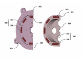
상기 동력발생기(200)는 도 2에 도시한 바와 같이, 프레임(210)에 전방 회전자(240)와 후방 회전자(250)의 회전을 지지하는 베어링 모듈(220)을 장착하여 스냅 링 또는 로크 너트와 같은 고정구(270)로 고정하고 상기 전방 회전자(240)와 상기 후방 회전자(250)를 상기 베어링 모듈(220)에 장착하여 로크 너트(260)로 고정하고 상기 전방 회전자(240)와 상기 후방 회전자(250) 주위에 자기장을 형성하는 구동자 모듈(230)들을 상기 프레임(210)에 장착한 것이다.2, the
상세하게는 상기 동력발생기(200)는 전방 회전자(240)와, 후방 회전자(250)와, 상기 전방 회전자(240)와 상기 후방 회전자(250)를 장착하여 회전을 지지하는 베어링 모듈(220)과, 상기 전방 회전자(240)와 상기 후방 회전자(250) 주위에 자기장을 형성하는 구동자 모듈(230)들과, 상기 베어링 모듈(220)과 상기 구동자 모듈(230)을 장착하는 프레임(210)과, 상기 전방 회전자(240)와 상기 후방 회전자(250)를 상기 베어링 모듈(220)에 고정하는 로크 너트(260)들과, 상기 베어링 모듈(220)을 상기 프레임(210)에 고정하는 고정구(270)를 포함한다.More specifically, the
상기 구성에서 상기 프레임(210)은 도 3에 도시한 바와 같이, 원통 형상으로 이루어진 몸체의 축을 중심으로 앞쪽과 뒷쪽의 내면(218)에 기준점(211)에 맞추어 각각 등 간격으로 영구자석 매입 구멍(213)을 원주 축선 방향으로 형성하고 내주 면에 상기 베어링 모듈(220)의 장착 공간과 베어링 냉각 공간(212)을 형성하고 몸체의 앞면과 뒷면에 상기 풀리 세트(500)의 지지대(540)와 상기 익스팬더 하우징(650)과 상기 후방 구동자 모듈(350)의 장착 면(214)들을 형성한 형상을 가진 것이다.3, the
상세하게는 상기 프레임(210)은 원통 형상으로 이루어진 몸체의 축을 중심으로 앞쪽과 뒤쪽의 내면(218)에 기준점(211)에 맞추어 각각 등 간격으로 2n개 (n은 4 이상 정수) 또는 3n개의 (n은 2 이상 정수) 영구자석 매입 구멍(213)을 원주 축선 방향으로 형성하고 내주 면에 그리스 윤활 방식의 베어링과 오일 윤활 방식의 베어링과 공기 냉각방식의 베어링과 그리고 자기 베어링 중 어느 하나로 하는 상기 베어링 모듈(220)의 장착 공간과 냉각 공간(212)을 형성하고 몸체의 앞면과 뒷면에 상기 풀리 세트(500)의 지지대(540)와 상기 익스팬더 하우징(650)과 상기 후방 구동자 모듈(350)의 장착 면(214)들을 형성한 형상을 가진다.In detail, the
상기 베어링 모듈(220)은 도 4에 도시한 바와 같이, 환봉 형상으로 이루어진 몸체의 외주 면에 베어링 장착 면(223)과 베어링 고정 턱(222)과 상기 전방 회전자(240)와 후방 회전자(250)의 위상을 고정하는 고정 홈(224)들과 나사산(225)들을 형성한 샤프트(221)에 회전을 지지하는 베어링(226)을 장착하고 위상을 고정하는 고정구(227)를 장착한 것이다. 또한, 상기 베어링 모듈(220)은 상기 전방 회전자(240)와 상기 후방 회전자(250)의 최대 회전수에 따라 내구 수명을 보장하는 허용 한계를 넘지 않는 그리스 공급 냉각방식의 베어링과 오일 공급 냉각방식의 베어링과 공기 냉각방식의 베어링과 자기 베어링 중 어느 하나의 베어링(226)을 선택하여 적용한 것이다.4, the
상세하게는 상기 베어링 모듈(220)은 환봉 형상으로 이루어진 몸체의 외주 면에 베어링 장착 면(223)과 베어링 고정 턱(222)과 상기 전방 회전자(240)와 상기 후방 회전자(250)의 위상을 고정하는 고정 홈(224)들과 나사산(225)들을 형성한 샤프트(221)와, 그리스 공급 냉각방식의 베어링과 오일 공급 냉각방식의 베어링과 공기 냉각방식의 베어링과 자기 베어링 중 어느 하나의 베어링(226)과, 위상을 고정하는 고정구(227)를 포함한다.The
상기 전방 회전자(240)와 상기 후방 회전자(250)는 도 5에 도시한 바와 같이, 원반 형상으로 이루어진 몸체의 중심에 원통형 돌출부(244)를 형성하여 내주 면에 위상을 고정하는 슬롯 홈(243)을 형성하고 몸체의 원주 축선 상에 슬롯 홈(243)에 맞추어 등 간격으로 영구자석 매입 구멍(245)들을 형성한 형상을 가진 회전판(242)의 영구자석 매입 구멍(245)들에 슬롯 홈(243)에 맞추어 영구자석(246)들을 N극과 S극을 교대로 매입하여 부착한 것이다.As shown in FIG. 5, the
상세하게는 상기 전방 회전자(240)와 상기 후방 회전자(250)는 원반 형상으로 이루어진 몸체의 중심에 원통형 돌출부(244)를 형성하여 내주 면에 위상을 고정하는 슬롯 홈(243)을 형성하고 몸체의 원주 축선 상에 슬롯 홈(243)에 맞추어 등 간격으로 2n개의 (이하 n은 2 이상 정수) 영구자석 매입 구멍(245)을 형성한 형상을 가진 회전판(242)과, 상기 회전판(242)의 슬롯 홈(243)에 맞추어 영구자석 매입 구멍(245)들에 N극과 S극을 교대로 매입하여 부착한 2n개의 영구자석(246)을 포함한다.Specifically, the
상기 구동자 모듈(230)은 도 6에 도시한 바와 같이, 상기 프레임(210)의 기준점(211)에 맞추어 상기 프레임(210)의 영구자석 매입 구멍(213)들에 영구자석(236)들을 N극과 S극을 교대로 매입하여 부착하거나 3상 배열하여 매입하여 부착한 것이다.6, the
상세하게는 상기 구동자 모듈(230)은 상기 프레임(210)의 기준점(211)에 맞추어 상기 프레임(210)의 영구자석 매입 구멍(213)들에 2n개를 (n은 4 이상 정수) N극과 S극을 교대로 매입하여 부착하거나 3n개를 (n은 2 이상 정수) 3상 배열하여 매입하여 부착한 영구자석(236)을 포함한다.More specifically, the
상기 전방 구동자 모듈(310)은 도 7에 도시한 바와 같이, 한쪽 면이 닫힌 원통 형상으로 이루어진 몸체에 상기 풀리 세트(500)의 샤프트(520)와의 장착 면(315)을 형성하고 기준점(311)에 맞추어 상기 전방 회전자(240) 주위의 원주 방향으로 일정 간격을 두고 등 간격으로 영구자석 매입 구멍(313)들을 형성한 고정대(312)의 영구자석 매입 구멍(313)들에 기준점(311)에 맞추어 영구자석(316)들을 N극과 S극을 교대로 매입하여 부착하거나 3상 배열하여 매입하여 부착한 것이다.7, the
상세하게는 상기 전방 구동자 모듈(310)은 한쪽 면이 닫힌 원통 형상으로 이루어진 몸체에 상기 풀리 세트(500)의 샤프트(520)와의 장착 면(315)을 형성하고 기준점(311)에 맞추어 상기 전방 회전자(240) 주위의 원주 방향으로 일정 간격을 두고 등 간격으로 2n개 (이하 n은 4 이상 정수) 또는 3n개의 (이하 n은 2 이상 정수) 영구자석 매입 구멍(313)을 형성한 고정대(312)와, 상기 고정대(312)의 기준점(311)에 맞추어 2n개의 영구자석 매입 구멍(313)에 N극과 S극을 교대로 매입하여 부착하거나 3n개의 영구자석 매입 구멍(313)에 3상 배열하여 매입하여 부착한 2n개 또는 3n개의 영구자석(316)을 포함한다.Specifically, the
상기 후방 구동자 모듈(350)은 도 7에 도시한 바와 같이, 한쪽 면이 닫힌 원통 형상으로 이루어진 몸체에 상기 익스팬더 하우징(650)과 상기 동력발생기(200)와의 장착 면(315)을 형성하고 기준점(311)에 맞추어 상기 후방 회전자(250) 주위의 원주 방향으로 일정 간격을 두고 등 간격으로 영구자석 매입 구멍(313)들을 형성한 고정대(312)의 영구자석 매입 구멍(313)들에 기준점(311)에 맞추어 영구자석(316)들을 N극과 S극을 교대로 매입하여 부착하거나 3상 배열하여 매입하여 부착한 것이다.7, the
상세하게는 상기 후방 구동자 모듈(350)은 한쪽 면이 닫힌 원통 형상으로 이루어진 몸체에 상기 익스팬더 하우징(650)과 상기 동력발생기(200)와의 장착 면(315)을 형성하고 기준점(311)에 맞추어 상기 후방 회전자(250) 주위의 원주 방향으로 일정 간격을 두고 등 간격으로 2n개 (이하 n은 4 이상 정수) 또는 3n개의 (이하 n은 2 이상 정수) 영구자석 매입 구멍(313)을 형성한 고정대(312)와, 상기 고정대(312)의 기준점에 맞추어 2n개의 영구자석 매입 구멍(313)에 N극과 S극을 교대로 매입하여 부착하거나 3n개의 영구자석 매입 구멍(313)에 3상 배열하여 매입하여 부착한 2n개 또는 3n개의 영구자석(316)을 포함한다.More specifically, the
도 1에 도시한 바와 같이, 상기 동력발생기(200)의 전방 회전자(240)와 후방 회전자(250)는 상기 프레임의(210) 축선 방향으로 자속의 방향이 향하고, 상기 동력발생기(200)의 구동자 모듈(230)들과 상기 전방 구동자 모듈(310)과 상기 후방 구동자 모듈(350)은 상기 동력발생기(200)의 전방 회전자(240)와 후방 회전자(250) 주위에 일정 간격을 두고 직각 방향으로 자속의 방향이 향한 것이다.1, the
상세하게는 상기 동력발생기(200)의 전방 회전자(240)와 후방 회전자(250)는 자속의 방향이 상기 프레임(210)의 축선 방향을 향하고 상기 동력발생기(200)의 구동자 모듈(230)들과 상기 전방 구동자 모듈(310)과 상기 후방 구동자 모듈(350)은 상기 동력발생기(200)의 전방 회전자(240)와 후방 회전자(250) 주위에 일정 간격을 두고 자속의 방향이 직각으로 향한 것이다.The
상기 익스팬더(610)는 원주 형상의 몸체의 중심에 관통 구멍을 형성하고 외주 면에 회전 축을 중심으로 뒤쪽에 원형 판이 있고 몸체의 외주 면에 날개들이 방사상 등 간격으로 형성되어 원형 판의 축선 직각 반지름 방향에서 축선 방향으로 회전 방향으로 날개가 구부러져 향하여 점점 좁아지는 유로를 형성한 형상을 가진 것이다. 또한, 날개들이 회전 반대 방향으로 구부러져 향하여 점점 좁아지는 유로를 형성하는 것도 무방하다.The
상기 익스팬더 하우징(650)은 상기 익스팬더(610)로 흡입공기를 유도하는 공기 흡입구와 유입 단면적이 점점 좁아지는 달팽이 껍질 모양의 스크롤과 노즐 공간으로 반지름 방향에서 흘러들어오는 공기의 유속을 높여 한곳으로 모아 상기 익스팬더(610)로 유입시키고 상기 익스팬더(610)에서 단열 팽창하여 나온 공기의 압력에너지를 속도에너지로 변환하여 토출하는 공기 배출구의 형상을 가진 것이다.The
다음으로, 작용 및 작동에 대해 설명한다.Next, the operation and operation will be described.
냉각공기 공급장치는 베어링(530)과 샤프트(520)가 설치된 지지대(540)에 내연기관의 크랭크 축의 회전 동력으로 회전하는 풀리(510)가 장착된 상기 풀리 세트(500)와, 상기 익스팬더 하우징(650)의 흡기 통로에 상기 익스팬더(610)가 배치되어 있으며, 상기 풀리 세트(500)와 상기 익스팬더(610) 사이에 동력발생기(200)와 전방 구동자 모듈(310)과 후방 구동자 모듈(350)로 구성된 상기 동력전달장치(100)가 개재되어 있다. 흡기 통로는 외부 공기가 상기 익스팬더 하우징(650)의 공기 흡입구로 유입하여 상기 익스팬더 하우징(650)의 스크롤과 노즐과 상기 익스팬더(610)를 거쳐 공기 배출구로 연결된다.The cooling air supply device includes the
상기 동력전달장치(100)의 동력발생기(200)는 뒤쪽에 후방 구동자 모듈(350)과 상기 익스팬더(610)와 상기 익스팬더 하우징(650)을 장착하고 앞쪽은 상기 풀리 세트(500)의 지지대(540)에 장착되고, 전방 구동자 모듈(310)은 상기 샤프트(520)에 장착되어 있다. 또한, 상기 동력발생기(200)와 상기 지지대(540), 상기 동력발생기(200)와 상기 익스팬더 하우징(650) 사이에 공간 확보용 어답터를 장착하여도 좋다.The
상기 전방 구동자 모듈(310)은 상기 동력발생기(200) 주위의 원주 방향으로 일정 간격을 두고 상기 동력발생기(200)의 전방 회전자(240)와 자속의 방향이 직각으로 향하도록 배치된다.The
즉, 상기 전방 회전자(240)의 영구자석(246)들은 자기장의 방향이 상기 프레임(210)의 축선 방향으로 향하도록 하여 2n개가 (n은 2 이상 정수) N극과 S극을 교대로 매입하여 부착되고 상기 전방 구동자 모듈(310)의 영구자석(316)들은 상기 동력발생기(200) 주위의 원주 방향으로 일정 간격을 두고 상기 전방 회전자(240)와 자기장의 방향이 직각으로 향하도록 하여 2n개가 (n은 4 이상 정수) N극과 S극을 교대로 매입하여 부착된 것이다.That is, the
도 8에 도시한 바와 같이 평면상에 전개하면, 상기 샤프트(520)가 정지상태에서는 상기 전방 회전자(240)의 N극 영구자석(246)들은 상기 전방 구동자 모듈(310)의 영구자석(316)들의 N극과 S극 사이에 위치하거나 또는 S극들과 마주보는 위치에서 자기장의 평형을 이루게 된다. 상기 전방 회전자(240)의 S극 영구자석(246)들은 상기 전방 구동자 모듈(310)의 N극과 S극 영구자석(316) 사이에 위치하거나 또는 S극들과 마주보는 위치에서 자기장의 평형을 이루게 된다.8, the N pole
상기 샤프트(520)가 회전하게 되면 상기 샤프트(520)에 장착된 상기 전방 구동자 모듈(310)의 영구자석(316)들이 회전하며 상기 전방 회전자(240)의 영구자석(246)들과 90도 위상으로 당기고 미는 인력과 척력의 유도 자기장의 회전력을 만들어 상기 전방 회전자(240)를 가속 회전하게 된다.When the
따라서, 상기 샤프트(520)의 회전 동력을 받아 상기 전방 구동자 모듈(310)은 상기 영구자석(316)들이 상기 샤프트(520)의 축선 지름 방향으로 N극과 S극이 교대로 배치된 가상의 자기장 회전 모멘트 축을 만들어 회전하고 상기 전방 회전자(240)는 상기 전방 구동자 모듈(310)의 내주 면의 주위에 일정한 간격을 두고 상기 영구자석(246)들이 상기 베어링 모듈(220)의 축선 방향으로 N극과 S극을 교대로 배치된 가상의 자기장 회전 모멘트 축을 형성하여 상기 전방 구동자 모듈(310)이 회전하며 상기 전방 회전자(240)와 밀고 당기는 인력과 척력으로 유성 운동의 회전력을 만들어 상기 전방 회전자(240)를 가속 회전시키는 것이다.The
또한, 상기 전방 회전자(240)의 영구자석(246)들은 자기장의 방향이 상기 프레임(210)의 축선 방향으로 향하도록 하여 2n개가 (n은 2 이상 정수) N극과 S극을 교대로 매입하여 부착되고 상기 전방 구동자 모듈(310)의 영구자석(316)들은 상기 전방 회전자(240)와 자기장의 방향이 직각으로 향하도록 하여 3n개가 (n은 2 이상 정수) 3상이 되도록 매입하여 부착된 것이다.The
상기 샤프트(520)가 정지상태에서는 상기 전방 회전자(240)의 N극 영구자석(246)들은 상기 전방 구동자 모듈(310)의 영구자석(316)들의 N극과 S극, S극과 N극 사이에 위치하거나 또는 S극과 N극과 마주보는 위치에서 자기장의 평형을 이루게 된다. S극 영구자석(246)들은 상기 전방 구동자 모듈(310)의 영구자석(316)들의 S극과 N극과 마주보거나 S극과 S극, N극과 N극 사이에 위치하여 자기 평형을 이루게 된다.The N pole
상기 샤프트(520)가 회전하게 되면 상기 샤프트(520)에 장착된 상기 전방 구동자 모듈(310)의 영구자석(316)들이 회전하며 상기 전방 회전자(240)의 영구자석(246)들과 120도 위상으로 당기고 미는 인력과 척력의 유도 자기장의 회전력을 만들어 상기 전방 회전자(240)를 가속 회전하게 된다.When the
따라서, 상기 샤프트(520)의 회전 동력을 받아 상기 전방 구동자 모듈(310)은 상기 영구자석(316)들이 상기 샤프트(520)의 축선 지름 방향으로 N, N, N극과 S, S, S극의 3상이 되도록 배치되어 가상의 자기장 회전 모멘트 축을 만들어 회전하고 상기 전방 회전자(240)는 상기 전방 구동자 모듈(310)의 내주 면의 주위에 일정한 간격을 두고 상기 영구자석(246)들이 상기 베어링 모듈(220)의 축선 방향으로 N극과 S극을 교대로 배치된 가상의 자기장 회전 모멘트 축을 형성하여 상기 전방 구동자 모듈(310)이 회전하며 상기 전방 회전자(240)와 밀고 당기는 인력과 척력으로 유성 운동의 회전력을 만들어 상기 전방 회전자(240)를 가속 회전시키는 것이다.Accordingly, the
예를 들면, 도 9에 도시한 바와 같이 유성기어열에서 링 기어(820)가 회전하면 유성 기어 캐리어(840)의 유성 기어(830)가 선 기어(810)를 균일하게 밀어내면서 가속 회전시키는 원리가 적용된다.9, when the
한편, 상기 동력발생기(200)의 전방 회전자(240)와 후방 회전자(250)는 상기 프레임(210)의 원주 축선 상에 상기 프레임의(210) 축선 방향으로 자속의 방향이 향하여 배치되고, 상기 동력발생기(200)의 구동자 모듈(230)들과 상기 후방 구동자 모듈(350)은 상기 전방 회전자(240)와 상기 후방 회전자(250)의 주위에 상기 프레임(210)의 원주 방향으로 상기 일정 간격을 두고 배치되어 자속의 방향이 상기 전방 회전자(240)와 상기 후방 회전자(250)의 자속의 방향과 직각으로 향하도록 하여 배치된다.The
즉, 상기 전방 회전자(240)와 상기 후방 회전자(250)의 영구자석(246)들은 자기장의 방향이 상기 프레임(210)의 축선 방향으로 향하도록 하여 2n개가 (n은 2 이상 정수) N극과 S극을 교대로 매입하여 부착되고 상기 동력발생기(200)의 구동자 모듈(230)들의 영구자석(236)들과 상기 후방 구동자 모듈(350)의 영구자석(316)들은 상기 전방 회전자(240)와 상기 후방 회전자(250)의 영구자석(246)들와 자기장의 방향이 직각으로 향하도록 하여 2n개가 (n은 4 이상 정수) N극과 S극을 교대로 매입하여 부착된 것이다.That is, the
도 10에 도시한 바와 같이 평면상에 전개하면, 상기 전방 구동자 모듈(310)이 정지상태에서는 상기 전방 회전자(240)의 N극 영구자석(246)들은 상기 구동자 모듈(230)의 영구자석(236)들의 N극과 S극 사이에 위치하거나 또는 S극들과 마주보는 위치에서 자기장의 평형을 이루게 된다. 상기 전방 회전자(240)의 S극 영구자석(246)들은 상기 구동자 모듈(230)의 영구자석(236)들의 N극과 S극 사이에 위치하거나 또는 S극들과 마주보는 위치에서 자기장의 평형을 이루게 된다.10, the N-pole
상기 전방 구동자 모듈(310)이 회전하며 만드는 유도 자기장의 회전력에 의해 상기 전방 회전자(240)가 회전 자기장으로 회전하여 화살표 방향으로 가속하여 이동하면 상기 전방 회전자(240)의 영구자석(246)들은 화살표 방향으로 동시에 이동하면서 상기 구동자 모듈(230)의 영구자석(236)들과 90도 위상으로 당기고 미는 인력과 척력의 자기장의 추진력을 얻게 되어 가속하게 된다.When the
따라서, 상기 전방 구동자 모듈(310)의 회전 동력을 받아 상기 전방 회전자(240)는 상기 영구자석(246)들이 상기 베어링 모듈(220)의 축선 방향으로 N극과 S극이 교대로 배치된 가상의 자기장 회전 모멘트 축을 만들어 회전하고 상기 구동자 모듈(230)은 상기 전방 회전자(240)의 주위에 일정한 간격을 두고 상기 영구자석(236)들이 상기 베어링 모듈(220)의 축선 지름 방향으로 N극과 S극을 교대로 배치되어 자기장을 형성하여 상기 전방 회전자(240)가 회전하며 상기 구동자 모듈(230)이 형성하는 자기장과 밀고 당기는 인력과 척력으로 회전력을 만들어 가속 회전하는 것이다. 상기 후방 회전자(250)와 상기 구동자 모듈(230) 그리고 상기 후방 회전자(250)와 상기 후방 구동자 모듈(350)도 동일하게 설명된다.The
또한, 상기 전방 회전자(240)와 상기 후방 회전자(250)의 영구자석(246)들은 자기장의 방향이 상기 프레임(210)의 축선 방향으로 향하도록 하여 2n개가 (n은 2 이상 정수) N극과 S극을 교대로 매입하여 부착되고 상기 동력발생기(200)의 구동자 모듈(230)들과 상기 후방 구동자 모듈(350)의 영구자석(346)들은 상기 전방 회전자(240)와 상기 후방 회전자(250)와 자기장의 방향이 직각으로 향하도록 하여 3n개가 (n은 2 이상 정수) 3상이 되도록 매입 부착된 것이다.The
상기 전방 구동자 모듈(310)이 정지상태에서는 상기 전방 회전자(240)의 N극 영구자석(246)들은 상기 구동자 모듈(230)의 영구자석(236)들의 N극과 S극, S극과 N극 사이에 위치하거나 또는 S극과 N극과 마주보는 위치에서 자기장의 평형을 이루게 된다. S극 영구자석(246)들은 상기 구동자 모듈(230)의 영구자석(236)들의 S극과 N극과 마주보거나 S극과 S극, N극과 N극 사이에 위치하여 자기 평형을 이루게 된다.The N pole
상기 전방 구동자 모듈(310)이 회전하며 만드는 유도 자기장의 회전력에 의해 상기 전방 회전자(240)가 회전 자기장으로 회전하여 화살표 방향으로 가속하여 이동하면 상기 전방 회전자(240)의 영구자석(246)들은 화살표 방향으로 동시에 이동하면서 상기 구동자 모듈(230)의 영구자석(236)들과 120도 위상으로 당기고 미는 인력과 척력의 추진력을 얻게 되어 가속 회전하게 된다.When the
따라서, 상기 전방 구동자 모듈(310)의 회전 동력을 받아 상기 전방 회전자(240)는 상기 영구자석(246)들이 상기 베어링 모듈(220)의 축선 방향으로 N극과 S극이 교대로 배치된 가상의 자기장 회전 모멘트 축을 만들어 회전하고 상기 구동자 모듈(230)은 상기 전방 회전자(240)의 주위에 일정한 간격을 두고 상기 영구자석(236)들이 상기 베어링 모듈(220)의 축선 지름 방향으로 N, N, N극과 S, S, S극의 3상이 되도록 배치되어 자기장을 형성하여 상기 전방 회전자(240)가 회전하며 상기 구동자 모듈(230)이 형성하는 자기장과 밀고 당기는 인력과 척력으로 회전력을 만들어 가속 회전하는 것이다. 상기 후방 회전자(250)와 상기 구동자 모듈(230) 그리고 상기 후방 회전자(250)와 상기 후방 구동자 모듈(350)도 동일하게 설명된다.The
예를 들면, 자기부상열차에서 차륜이 원동기로 구동되어 차대가 일정 속도 이상 가속되면 차대에 설치된 전기자와 일정한 간격을 두고 설치된 리액션플레이트 사이의 전자력을 이용하여 주행하는 선형유도모터(LIM : Linear Induction Motor) 구동방식의 원리가 적용된다.For example, in a magnetic levitation train, when a wheel is driven by a prime mover and the vehicle is accelerated above a certain speed, a linear induction motor (LIM) that travels using electromagnetic force between the armature installed in the undercarriage and a reaction plate ) Drive principle is applied.
또한 차대에 설치된 전기자와 일정한 간격을 두고 설치된 리액션플레이트 사이의 전자력을 이용하여 주행하는 선형동기모터(LSM : the linear synchronous motor) 구동방식의 원리가 적용된다.The principle of driving the linear synchronous motor (LSM) driving by using the electromagnetic force between the armature installed on the undercarriage and the reaction plate arranged at a certain distance is applied.
한편, 내연기관이 시동되면 내연기관의 흡입압에 의해 외부공기가 상기 익스팬더 하우징(650)의 공기 흡입구로 유입하여 스크롤과 노즐과 상기 익스팬더(610)를 거쳐 공기 배출구로 배출되는 공기 유동의 관성력으로 상기 익스팬더(610)를 회전시키며 상기 익스팬더(610)는 상기 베어링 모듈(220)의 샤프트(221)에 장착된 상기 전방 회전자(240)와 상기 후방 회전자(250)에 회전 동력을 전달하게 된다.On the other hand, when the internal combustion engine is started, external air is introduced into the air intake port of the
이때, 상기 익스팬더(610)에서 공급되는 회전 동력을 받은 상기 전방 회전자(240)와 상기 후방 회전자(250)는 상기 구동자 모듈(230)과 상기 후방 구동자 모듈(350)이 형성하는 자기장과 밀고 당기는 인력과 척력으로 회전력을 만들어 가속 회전하게 된다.The
상기와 같이 구성된 냉각공기 공급장치에서는 내연기관의 크랭크 축의 회전 동력으로 회전하는 상기 풀리(510)에서 공급되는 회전 동력으로 상기 전방 구동자 모듈(310)에서 만들어지는 유도 자기장과 상기 동력발생기(200)가 만드는 회전 자기장과 상기 동력발생기(200)가 상기 후방 구동자 모듈(350)과 만드는 회전 자기장과 상기 익스팬더(610)에서 공급되는 회전 동력으로 상기 동력발생기(200)가 만드는 회전 자기장과 상기 동력발생기(200)가 상기 후방 구동자 모듈(350)과 만드는 회전 자기장으로 회전력을 만들어 상기 익스팬더(610)에 회전 동력을 전달하여 공기를 확장하여 공기 밀도가 높은 찬공기를 내연기관에 공급한다.In the cooling air supply apparatus configured as described above, the induction magnetic field generated by the
상기 동력전달장치(200)의 회전력은 영구자석들의 자기밀도와 자기장의 접촉 면적과 영구자석들의 장착 지름 피치와 일정한 간격을 두고 직각으로 마주보는 영구자석들 간의 간격을 조정하여 결정된다.The rotational force of the
또한, 상기 동력전달장치(200)는 영구자석들의 인력과 척력의 상호작용으로 자기장의 회전력을 만들어 구동하기 때문에 높은 구동 효율로 소음 발생이 거의 발생하지 않으며 내구성이 좋고 구동 비용이 없다.In addition, since the
기타, 본 발명은 상기 실시예에 한정되지 않고, 본 발명의 요지를 벗어나지 않는 범위에서 다양하게 변경될 수 있음은 물론이다.It is needless to say that the present invention is not limited to the above-described embodiment, and various modifications may be made without departing from the gist of the present invention.
100: 동력전달장치 110: 동력발생기
210: 프레임 220: 베어링 모듈
230: 구동자 모듈 240: 전방 회전자
250: 후방 회전자 310: 전방 구동자 모듈
320: 후방 구동자 모듈 510: 풀리
610: 익스팬더 650: 익스팬더 하우징100: Power transmission device 110: Power generator
210: frame 220: bearing module
230: driver module 240: front rotor
250: rear rotor 310: front driver module
320: rear driver module 510: pulley
610: expander 650: expander housing
Claims (9)
상기 동력전달장치는 동력발생기와 상기 동력발생기의 앞쪽과 뒤쪽에 배치되어 상기 동력발생기 주위에 자기장을 형성하는 전방 구동자 모듈과 후방 구동자 모듈로 구성되어 상기 동력발생기는 상기 익스팬더와 상기 익스팬더 하우징을 장착하여 상기 지지대에 장착되고, 상기 전방 구동자 모듈은 상기 샤프트에 장착되고, 상기 후방 구동자 모듈은 상기 동력발생기에 장착되어 상기 풀리와 상기 익스팬더의 회전 동력을 공급받으며,
상기 풀리에서 공급되는 회전 동력으로 상기 전방 구동자 모듈에서 만들어지는 유도 자기장과 상기 동력발생기가 만드는 회전 자기장과 상기 동력발생기가 상기 후방 구동자 모듈과 만드는 회전 자기장과 상기 익스팬더에서 공급되는 회전 동력으로 상기 동력발생기가 만드는 회전 자기장과 상기 동력발생기가 상기 후방 구동자 모듈과 만드는 회전 자기장으로 회전력을 만들어 회전력을 높여 상기 익스팬더에 회전 동력을 전달하는 것을 특징으로 하는 냉각공기 공급장치.A pulley set having a pulley driven by a rotational power of a crankshaft of an internal combustion engine mounted on a support base provided with a bearing and a shaft, an expander for expanding the intake air, an expander housing surrounding the expander, A cooling air supply apparatus including a delivery device,
The power transmission apparatus includes a power generator and a front driver module and a rear driver module disposed at the front and rear sides of the power generator to form a magnetic field around the power generator, and the power generator includes the expander and the expander housing Wherein the front driver module is mounted on the shaft and the rear driver module is mounted on the power generator and is supplied with rotational power of the pulley and the expander,
A rotational magnetic field generated by the front drive module, a rotational magnetic field generated by the power generator, and a rotational magnetic field generated by the rear drive module and a rotational power supplied from the expander, Wherein the rotational force is generated by a rotational magnetic field generated by the power generator and a rotational magnetic field generated by the power generator by the rear actuator module to increase the rotational force to transmit the rotational power to the expander.
상기 동력발생기는 전방 회전자와, 후방 회전자와, 상기 전방 회전자와 상기 후방 회전자를 장착하여 회전을 지지하는 베어링 모듈과, 상기 전방 회전자와 상기 후방 회전자 주위에 자기장을 형성하는 구동자 모듈들과, 상기 베어링 모듈과 상기 구동자 모듈을 장착하는 프레임과, 상기 전방 회전자와 상기 후방 회전자를 상기 베어링 모듈에 고정하는 로크 너트들과, 상기 베어링 모듈을 상기 프레임에 고정하는 고정구를 포함하는 것을 특징으로 하는 냉각공기 공급장치.The method according to claim 1,
The power generator includes a bearing module for mounting a front rotor, a rear rotor, the front rotor and the rear rotor to support the rotation, and a drive for forming a magnetic field around the front rotor and the rear rotor. Lock nuts for securing the front rotor and the rear rotor to the bearing module, and fasteners for fixing the bearing module to the frame, Wherein the cooling air supply device comprises:
상기 프레임은 원통 형상으로 이루어진 몸체의 축을 중심으로 앞쪽과 뒤쪽의 내면에 기준점에 맞추어 각각 등 간격으로 2n개 (n은 4 이상 정수) 또는 3n개의 (n은 2 이상 정수) 영구자석 매입 구멍을 원주 축선 방향으로 형성하고 내주 면에 그리스 윤활 방식의 베어링과 오일 윤활 방식의 베어링과 공기 냉각방식의 베어링과 그리고 자기 베어링 중 어느 하나로 하는 상기 베어링 모듈의 장착 공간과 냉각 공간을 형성하고 몸체의 앞면과 뒷면에 상기 풀리 세트의 지지대와 상기 익스팬더 하우징과 상기 후방 구동자 모듈의 장착 면을 형성한 형상을 가진 것을 특징으로 하는 냉각공기 공급장치.The method of claim 2,
The frame is formed by arranging 2n (n is an integer of 4 or more) or 3n (n is an integer of 2 or more) permanent magnet embedding holes in the inner and outer surfaces of the front and rear sides of the cylindrical body, And a bearing space of the bearing module and a cooling space are formed on the inner circumferential surface of the inner bearing surface by using grease lubrication type bearing, oil lubrication type bearing, air cooling type bearing and magnetic bearing, Wherein the support base of the pulley set, the expander housing, and the rear drive module are formed on the mounting surface.
상기 베어링 모듈은 환봉 형상으로 이루어진 몸체의 외주 면에 베어링 장착 면과 베어링 고정 턱과 상기 전방 회전자와 상기 후방 회전자의 위상을 고정하는 고정 홈들과 나사산들을 형성한 샤프트와, 그리스 공급 냉각방식의 베어링과 오일 공급 냉각방식의 베어링과 공기 냉각방식의 베어링과 자기 베어링 중 어느 하나의 베어링과, 위상을 고정하는 고정구를 포함하는 것을 특징으로 하는 냉각공기 공급장치.The method of claim 2,
The bearing module includes a shaft having a bearing mounting surface, a bearing fixing jaw, fixing grooves for fixing the phases of the front rotor and the rear rotor, and threads formed on the outer circumferential surface of the body, Wherein the cooling air supply device includes a bearing, an oil supply cooling type bearing, an air cooling type bearing and a magnetic bearing, and a fixture for fixing the phase.
상기 전방 회전자와 상기 후방 회전자는 원반 형상으로 이루어진 몸체의 중심에 원통형 돌출부를 형성하여 내주 면에 위상을 고정하는 슬롯 홈을 형성하고 몸체의 원주 축선 상에 슬롯 홈에 맞추어 등 간격으로 2n개의 (이하 n은 2 이상 정수) 영구자석 매입 구멍을 형성한 형상을 가진 회전판과, 상기 회전판의 슬롯 홈에 맞추어 영구자석 매입 구멍들에 N극과 S극을 교대로 매입하여 부착한 2n개의 영구자석을 포함하는 것을 특징으로 하는 냉각공기 공급장치.The method of claim 2,
The front rotor and the rear rotor are each formed with a cylindrical protrusion at the center of a disk-shaped body to form a slot groove for fixing a phase on the inner circumference surface, Wherein n is an integer of 2 or more) permanent magnet filling holes, and 2n permanent magnets in which N and S poles are alternately embedded in the permanent magnet buried holes in accordance with the slot grooves of the rotating plate The cooling air supply device comprising:
상기 구동자 모듈은 상기 프레임의 기준점에 맞추어 상기 프레임의 영구자석 매입 구멍들에 2n개를 (n은 4 이상 정수) N극과 S극을 교대로 매입하여 부착하거나 3n개를 (n은 2 이상 정수) 3상 배열하여 매입하여 부착한 영구자석을 포함하는 것을 특징으로 하는 냉각공기 공급장치.The method of claim 2,
The driver module alternately embeds 2n (n is an integer of 4 or more) N poles and S poles alternately in the permanent magnet buried holes of the frame according to the reference point of the frame, or attaches 3n (n is 2 or more Wherein the permanent magnets include three permanent magnets that are embedded and attached in a three-phase arrangement.
상기 전방 구동자 모듈은 한쪽 면이 닫힌 원통 형상으로 이루어진 몸체에 상기 풀리 세트의 샤프트와의 장착 면을 형성하고 기준점에 맞추어 상기 전방 회전자 주위의 원주 방향으로 일정 간격을 두고 등 간격으로 2n개 (이하 n은 4 이상 정수) 또는 3n개의 (이하 n은 2 이상 정수) 영구자석 매입 구멍을 형성한 고정대와, 상기 고정대의 기준점에 맞추어 2n개의 영구자석 매입 구멍에 N극과 S극을 교대로 매입하여 부착하거나 3n개의 영구자석 매입 구멍에 3상 배열하여 매입하여 부착한 2n개 또는 3n개의 영구자석을 포함하는 것을 특징으로 하는 냉각공기 공급장치.The method according to claim 1,
The front driver module has a cylindrical body with one side closed and a mounting surface of the pulley set with a shaft. The front driver module has a mounting surface of 2n pieces at regular intervals in the circumferential direction around the front rotor (Hereinafter, n is an integer of 4 or more) or 3n (n is an integer of 2 or more) permanent magnet buried holes, and alternately N and S poles are buried in 2n permanent magnet buried holes in accordance with the reference point of the fixed base Or 2n or 3n permanent magnets which are attached and embedded in 3n phase-embedded in 3n permanent magnet buried holes.
상기 후방 구동자 모듈은 한쪽 면이 닫힌 원통 형상으로 이루어진 몸체에 상기 익스팬더 하우징과 상기 동력발생기와의 장착 면을 형성하고 기준점에 맞추어 상기 후방 회전자 주위의 원주 방향으로 일정 간격을 두고 등 간격으로 2n개 (이하 n은 4 이상 정수) 또는 3n개의 (이하 n은 2 이상 정수) 영구자석 매입 구멍을 형성한 고정대와, 상기 고정대의 기준점에 맞추어 2n개의 영구자석 매입 구멍에 N극과 S극을 교대로 매입하여 부착하거나 3n개의 영구자석 매입 구멍에 3상 배열하여 매입하여 부착한 2n개 또는 3n개의 영구자석을 포함하는 것을 특징으로 하는 냉각공기 공급장치.The method according to claim 1,
Wherein the rear driver module comprises a body having a cylindrical shape with one side closed and a mounting surface between the expander housing and the power generator is formed on the rear side of the rear rotor, (Hereinafter, n is an integer of 4 or more) or 3n (n is an integer of 2 or more) permanent magnet embossing holes, and alternate N pole and S pole in 2n permanent magnet embedding holes in accordance with the reference point of the fixing table , Or 2n or 3n permanent magnets which are embedded in and attached to the 3n permanent magnet buried holes in a three-phase arrangement.
상기 동력발생기의 전방 회전자와 후방 회전자는 자속의 방향이 상기 프레임의 축선 방향을 향하고 상기 동력발생기의 구동자 모듈들과 상기 전방 구동자 모듈과 상기 후방 구동자 모듈은 상기 동력발생기의 전방 회전자와 후방 회전자 주위에 일정 간격을 두고 자속의 방향이 직각으로 향한 것을 특징으로 하는 냉각공기 공급장치.The method of claim 2,
The front rotor and the rear rotor of the power generator face the axial direction of the frame and the driver modules of the power generator and the front driver module and the rear driver module are connected to the front rotor of the power generator And the direction of the magnetic flux is oriented at right angles at a predetermined interval around the rear rotor.
Priority Applications (2)
| Application Number | Priority Date | Filing Date | Title |
|---|---|---|---|
| KR1020150126726A KR20170029754A (en) | 2015-09-08 | 2015-09-08 | Cooling Air Supply Device |
| PCT/KR2016/009979 WO2017043840A1 (en) | 2015-09-08 | 2016-09-06 | Cooling air supply device |
Applications Claiming Priority (1)
| Application Number | Priority Date | Filing Date | Title |
|---|---|---|---|
| KR1020150126726A KR20170029754A (en) | 2015-09-08 | 2015-09-08 | Cooling Air Supply Device |
Related Child Applications (1)
| Application Number | Title | Priority Date | Filing Date |
|---|---|---|---|
| KR1020170135968A Division KR101873892B1 (en) | 2017-10-19 | 2017-10-19 | Cooling Air Supply Device |
Publications (1)
| Publication Number | Publication Date |
|---|---|
| KR20170029754A true KR20170029754A (en) | 2017-03-16 |
Family
ID=58240208
Family Applications (1)
| Application Number | Title | Priority Date | Filing Date |
|---|---|---|---|
| KR1020150126726A KR20170029754A (en) | 2015-09-08 | 2015-09-08 | Cooling Air Supply Device |
Country Status (2)
| Country | Link |
|---|---|
| KR (1) | KR20170029754A (en) |
| WO (1) | WO2017043840A1 (en) |
Family Cites Families (5)
| Publication number | Priority date | Publication date | Assignee | Title |
|---|---|---|---|---|
| KR20020001313A (en) * | 2000-06-28 | 2002-01-09 | 이범수 | Super charger for car |
| KR100981925B1 (en) * | 2008-06-04 | 2010-09-13 | 주식회사 천인 | Power Transmission Device |
| JP2014125935A (en) * | 2012-12-26 | 2014-07-07 | Taiho Kogyo Co Ltd | Bearing structure of turbocharger and the turbocharger including the same |
| KR101429848B1 (en) * | 2013-02-13 | 2014-08-12 | 한승주 | Air Expander driven by Rotating Magnetic Field |
| KR20140114512A (en) * | 2013-03-15 | 2014-09-29 | 현대자동차주식회사 | Centrifugal supercharger and supercharging system for engine |
-
2015
- 2015-09-08 KR KR1020150126726A patent/KR20170029754A/en active Application Filing
-
2016
- 2016-09-06 WO PCT/KR2016/009979 patent/WO2017043840A1/en active Application Filing
Also Published As
| Publication number | Publication date |
|---|---|
| WO2017043840A1 (en) | 2017-03-16 |
Similar Documents
| Publication | Publication Date | Title |
|---|---|---|
| KR101429846B1 (en) | Air Charger driven by Rotating Magnetic Field | |
| US20160010648A1 (en) | Self-driven apparatus for charging expanded air | |
| KR101804209B1 (en) | Air Cooling Device | |
| JP6649277B2 (en) | Power transmission device using magnetic field | |
| KR101891548B1 (en) | Split Supercharger | |
| KR101873892B1 (en) | Cooling Air Supply Device | |
| KR101884574B1 (en) | Split Turbocharger | |
| JP2022019594A (en) | Cooling of electrical machines | |
| KR20170029754A (en) | Cooling Air Supply Device | |
| KR101907249B1 (en) | High-speed power generator | |
| KR101868292B1 (en) | Air Cooling Device | |
| KR20170038136A (en) | Split Turbocharger | |
| JP6654149B2 (en) | Variable power transmission | |
| KR101814939B1 (en) | Power transmission device using a magnetic field | |
| KR20170022066A (en) | Split Supercharger | |
| KR20170121138A (en) | Turbocharger attached to the accelerator | |
| KR20170046039A (en) | Turbocharger attached to the accelerator | |
| KR101930139B1 (en) | Power Transmission Device | |
| CN113131660A (en) | High-speed permanent magnet motor | |
| US20100301693A1 (en) | Rotational magnetic propulsion motors | |
| JP2005354886A (en) | Three-stage motor driving method, and power generation method and device thereof | |
| KR20170066173A (en) | High Speed Motor | |
| JP2006060987A (en) | Four-stage motor driving method, power generating method, and equipment of the same |
Legal Events
| Date | Code | Title | Description |
|---|---|---|---|
| A201 | Request for examination | ||
| AMND | Amendment | ||
| AMND | Amendment | ||
| AMND | Amendment | ||
| AMND | Amendment | ||
| AMND | Amendment | ||
| AMND | Amendment | ||
| AMND | Amendment | ||
| AMND | Amendment | ||
| E902 | Notification of reason for refusal | ||
| AMND | Amendment | ||
| E601 | Decision to refuse application | ||
| E601 | Decision to refuse application | ||
| E801 | Decision on dismissal of amendment | ||
| A107 | Divisional application of patent |