KR20170027719A - Method and apparatus for non-thermal nail, foot, and hand fungus treatment - Google Patents
Method and apparatus for non-thermal nail, foot, and hand fungus treatment Download PDFInfo
- Publication number
- KR20170027719A KR20170027719A KR1020167035272A KR20167035272A KR20170027719A KR 20170027719 A KR20170027719 A KR 20170027719A KR 1020167035272 A KR1020167035272 A KR 1020167035272A KR 20167035272 A KR20167035272 A KR 20167035272A KR 20170027719 A KR20170027719 A KR 20170027719A
- Authority
- KR
- South Korea
- Prior art keywords
- light emitting
- emitting diode
- light
- chamber
- finger
- Prior art date
Links
- 238000000034 method Methods 0.000 title claims abstract description 35
- 238000011282 treatment Methods 0.000 title claims description 71
- 241000233866 Fungi Species 0.000 title claims description 27
- 230000007246 mechanism Effects 0.000 claims description 25
- 125000006850 spacer group Chemical group 0.000 claims description 10
- 230000001954 sterilising effect Effects 0.000 claims description 9
- 238000002560 therapeutic procedure Methods 0.000 claims description 8
- 230000001225 therapeutic effect Effects 0.000 claims description 5
- 238000007906 compression Methods 0.000 claims description 3
- 230000006835 compression Effects 0.000 claims description 3
- 230000001678 irradiating effect Effects 0.000 claims description 3
- 230000000977 initiatory effect Effects 0.000 claims 1
- 208000015181 infectious disease Diseases 0.000 abstract description 8
- 238000001228 spectrum Methods 0.000 abstract description 3
- 210000000282 nail Anatomy 0.000 description 31
- 208000010195 Onychomycosis Diseases 0.000 description 16
- 238000005286 illumination Methods 0.000 description 9
- 230000006378 damage Effects 0.000 description 7
- 230000003287 optical effect Effects 0.000 description 7
- 230000000694 effects Effects 0.000 description 6
- 210000000056 organ Anatomy 0.000 description 5
- 206010017533 Fungal infection Diseases 0.000 description 4
- 241000223229 Trichophyton rubrum Species 0.000 description 4
- 230000002538 fungal effect Effects 0.000 description 4
- 239000000758 substrate Substances 0.000 description 4
- 239000003860 topical agent Substances 0.000 description 4
- 241000588724 Escherichia coli Species 0.000 description 3
- 208000031888 Mycoses Diseases 0.000 description 3
- 230000002411 adverse Effects 0.000 description 3
- 238000005516 engineering process Methods 0.000 description 3
- 230000002265 prevention Effects 0.000 description 3
- 230000004044 response Effects 0.000 description 3
- VHVPQPYKVGDNFY-DFMJLFEVSA-N 2-[(2r)-butan-2-yl]-4-[4-[4-[4-[[(2r,4s)-2-(2,4-dichlorophenyl)-2-(1,2,4-triazol-1-ylmethyl)-1,3-dioxolan-4-yl]methoxy]phenyl]piperazin-1-yl]phenyl]-1,2,4-triazol-3-one Chemical compound O=C1N([C@H](C)CC)N=CN1C1=CC=C(N2CCN(CC2)C=2C=CC(OC[C@@H]3O[C@](CN4N=CN=C4)(OC3)C=3C(=CC(Cl)=CC=3)Cl)=CC=2)C=C1 VHVPQPYKVGDNFY-DFMJLFEVSA-N 0.000 description 2
- XUMBMVFBXHLACL-UHFFFAOYSA-N Melanin Chemical compound O=C1C(=O)C(C2=CNC3=C(C(C(=O)C4=C32)=O)C)=C2C4=CNC2=C1C XUMBMVFBXHLACL-UHFFFAOYSA-N 0.000 description 2
- 239000003795 chemical substances by application Substances 0.000 description 2
- 150000001875 compounds Chemical class 0.000 description 2
- 206010012601 diabetes mellitus Diseases 0.000 description 2
- 201000010099 disease Diseases 0.000 description 2
- 208000037265 diseases, disorders, signs and symptoms Diseases 0.000 description 2
- 229920001971 elastomer Polymers 0.000 description 2
- 229960004884 fluconazole Drugs 0.000 description 2
- RFHAOTPXVQNOHP-UHFFFAOYSA-N fluconazole Chemical compound C1=NC=NN1CC(C=1C(=CC(F)=CC=1)F)(O)CN1C=NC=N1 RFHAOTPXVQNOHP-UHFFFAOYSA-N 0.000 description 2
- 230000006872 improvement Effects 0.000 description 2
- 229960004130 itraconazole Drugs 0.000 description 2
- 230000031700 light absorption Effects 0.000 description 2
- 230000000670 limiting effect Effects 0.000 description 2
- 239000000463 material Substances 0.000 description 2
- 230000007935 neutral effect Effects 0.000 description 2
- 230000008832 photodamage Effects 0.000 description 2
- 238000002428 photodynamic therapy Methods 0.000 description 2
- 239000004033 plastic Substances 0.000 description 2
- 229920003023 plastic Polymers 0.000 description 2
- 230000008569 process Effects 0.000 description 2
- 239000005060 rubber Substances 0.000 description 2
- 229910001220 stainless steel Inorganic materials 0.000 description 2
- 239000010935 stainless steel Substances 0.000 description 2
- 238000004659 sterilization and disinfection Methods 0.000 description 2
- DOMXUEMWDBAQBQ-WEVVVXLNSA-N terbinafine Chemical compound C1=CC=C2C(CN(C\C=C\C#CC(C)(C)C)C)=CC=CC2=C1 DOMXUEMWDBAQBQ-WEVVVXLNSA-N 0.000 description 2
- 229960002722 terbinafine Drugs 0.000 description 2
- 230000000699 topical effect Effects 0.000 description 2
- 241000894006 Bacteria Species 0.000 description 1
- 208000035143 Bacterial infection Diseases 0.000 description 1
- 241000538562 Banjos Species 0.000 description 1
- 208000017667 Chronic Disease Diseases 0.000 description 1
- 206010011409 Cross infection Diseases 0.000 description 1
- PEDCQBHIVMGVHV-UHFFFAOYSA-N Glycerine Chemical compound OCC(O)CO PEDCQBHIVMGVHV-UHFFFAOYSA-N 0.000 description 1
- 241000282412 Homo Species 0.000 description 1
- 241001465754 Metazoa Species 0.000 description 1
- 241000204031 Mycoplasma Species 0.000 description 1
- 229910052779 Neodymium Inorganic materials 0.000 description 1
- 206010029803 Nosocomial infection Diseases 0.000 description 1
- 229910000831 Steel Inorganic materials 0.000 description 1
- 208000002474 Tinea Diseases 0.000 description 1
- 241000893966 Trichophyton verrucosum Species 0.000 description 1
- 238000010521 absorption reaction Methods 0.000 description 1
- 230000009471 action Effects 0.000 description 1
- 239000013543 active substance Substances 0.000 description 1
- 238000004873 anchoring Methods 0.000 description 1
- 210000001557 animal structure Anatomy 0.000 description 1
- 230000000843 anti-fungal effect Effects 0.000 description 1
- 238000013459 approach Methods 0.000 description 1
- 238000003491 array Methods 0.000 description 1
- 208000022362 bacterial infectious disease Diseases 0.000 description 1
- 230000008901 benefit Effects 0.000 description 1
- 230000005540 biological transmission Effects 0.000 description 1
- 230000004397 blinking Effects 0.000 description 1
- 239000008280 blood Substances 0.000 description 1
- 210000004369 blood Anatomy 0.000 description 1
- 230000008859 change Effects 0.000 description 1
- 238000012512 characterization method Methods 0.000 description 1
- SCKYRAXSEDYPSA-UHFFFAOYSA-N ciclopirox Chemical compound ON1C(=O)C=C(C)C=C1C1CCCCC1 SCKYRAXSEDYPSA-UHFFFAOYSA-N 0.000 description 1
- 210000000078 claw Anatomy 0.000 description 1
- 238000004891 communication Methods 0.000 description 1
- 238000010276 construction Methods 0.000 description 1
- 230000008878 coupling Effects 0.000 description 1
- 238000010168 coupling process Methods 0.000 description 1
- 238000005859 coupling reaction Methods 0.000 description 1
- 238000001723 curing Methods 0.000 description 1
- 230000006735 deficit Effects 0.000 description 1
- 238000011161 development Methods 0.000 description 1
- 229940079593 drug Drugs 0.000 description 1
- 239000003814 drug Substances 0.000 description 1
- 230000005670 electromagnetic radiation Effects 0.000 description 1
- 238000010304 firing Methods 0.000 description 1
- 229920001821 foam rubber Polymers 0.000 description 1
- 230000037406 food intake Effects 0.000 description 1
- 238000009472 formulation Methods 0.000 description 1
- 230000006870 function Effects 0.000 description 1
- 208000024386 fungal infectious disease Diseases 0.000 description 1
- 230000002070 germicidal effect Effects 0.000 description 1
- 230000036541 health Effects 0.000 description 1
- 231100000334 hepatotoxic Toxicity 0.000 description 1
- 230000008595 infiltration Effects 0.000 description 1
- 238000001764 infiltration Methods 0.000 description 1
- 230000002401 inhibitory effect Effects 0.000 description 1
- 239000004922 lacquer Substances 0.000 description 1
- 238000013532 laser treatment Methods 0.000 description 1
- 239000007788 liquid Substances 0.000 description 1
- 238000009196 low level laser therapy Methods 0.000 description 1
- 210000004962 mammalian cell Anatomy 0.000 description 1
- 229910052751 metal Inorganic materials 0.000 description 1
- 239000002184 metal Substances 0.000 description 1
- 239000000203 mixture Substances 0.000 description 1
- 238000012986 modification Methods 0.000 description 1
- 230000004048 modification Effects 0.000 description 1
- 238000012544 monitoring process Methods 0.000 description 1
- 230000000877 morphologic effect Effects 0.000 description 1
- QEFYFXOXNSNQGX-UHFFFAOYSA-N neodymium atom Chemical compound [Nd] QEFYFXOXNSNQGX-UHFFFAOYSA-N 0.000 description 1
- 230000003040 nociceptive effect Effects 0.000 description 1
- 244000045947 parasite Species 0.000 description 1
- 230000035515 penetration Effects 0.000 description 1
- 239000003504 photosensitizing agent Substances 0.000 description 1
- 229920001296 polysiloxane Polymers 0.000 description 1
- 230000008092 positive effect Effects 0.000 description 1
- 230000003389 potentiating effect Effects 0.000 description 1
- 102000004169 proteins and genes Human genes 0.000 description 1
- 108090000623 proteins and genes Proteins 0.000 description 1
- 239000011347 resin Substances 0.000 description 1
- 229920005989 resin Polymers 0.000 description 1
- 210000001525 retina Anatomy 0.000 description 1
- 238000012552 review Methods 0.000 description 1
- 230000036555 skin type Effects 0.000 description 1
- 230000003068 static effect Effects 0.000 description 1
- 239000010959 steel Substances 0.000 description 1
- BWMISRWJRUSYEX-SZKNIZGXSA-N terbinafine hydrochloride Chemical compound Cl.C1=CC=C2C(CN(C\C=C\C#CC(C)(C)C)C)=CC=CC2=C1 BWMISRWJRUSYEX-SZKNIZGXSA-N 0.000 description 1
- 201000004647 tinea pedis Diseases 0.000 description 1
- 201000005882 tinea unguium Diseases 0.000 description 1
- 210000004906 toe nail Anatomy 0.000 description 1
- 229940100615 topical ointment Drugs 0.000 description 1
- 238000011269 treatment regimen Methods 0.000 description 1
- 238000001429 visible spectrum Methods 0.000 description 1
- XLYOFNOQVPJJNP-UHFFFAOYSA-N water Substances O XLYOFNOQVPJJNP-UHFFFAOYSA-N 0.000 description 1
- 238000004804 winding Methods 0.000 description 1
Images


Classifications
-
- A—HUMAN NECESSITIES
- A61—MEDICAL OR VETERINARY SCIENCE; HYGIENE
- A61N—ELECTROTHERAPY; MAGNETOTHERAPY; RADIATION THERAPY; ULTRASOUND THERAPY
- A61N5/00—Radiation therapy
- A61N5/06—Radiation therapy using light
- A61N5/0613—Apparatus adapted for a specific treatment
- A61N5/0624—Apparatus adapted for a specific treatment for eliminating microbes, germs, bacteria on or in the body
-
- A—HUMAN NECESSITIES
- A61—MEDICAL OR VETERINARY SCIENCE; HYGIENE
- A61L—METHODS OR APPARATUS FOR STERILISING MATERIALS OR OBJECTS IN GENERAL; DISINFECTION, STERILISATION OR DEODORISATION OF AIR; CHEMICAL ASPECTS OF BANDAGES, DRESSINGS, ABSORBENT PADS OR SURGICAL ARTICLES; MATERIALS FOR BANDAGES, DRESSINGS, ABSORBENT PADS OR SURGICAL ARTICLES
- A61L2/00—Methods or apparatus for disinfecting or sterilising materials or objects other than foodstuffs or contact lenses; Accessories therefor
- A61L2/02—Methods or apparatus for disinfecting or sterilising materials or objects other than foodstuffs or contact lenses; Accessories therefor using physical phenomena
- A61L2/08—Radiation
- A61L2/085—Infrared radiation
-
- A—HUMAN NECESSITIES
- A61—MEDICAL OR VETERINARY SCIENCE; HYGIENE
- A61N—ELECTROTHERAPY; MAGNETOTHERAPY; RADIATION THERAPY; ULTRASOUND THERAPY
- A61N5/00—Radiation therapy
- A61N5/06—Radiation therapy using light
- A61N5/0613—Apparatus adapted for a specific treatment
- A61N5/0616—Skin treatment other than tanning
-
- F—MECHANICAL ENGINEERING; LIGHTING; HEATING; WEAPONS; BLASTING
- F21—LIGHTING
- F21V—FUNCTIONAL FEATURES OR DETAILS OF LIGHTING DEVICES OR SYSTEMS THEREOF; STRUCTURAL COMBINATIONS OF LIGHTING DEVICES WITH OTHER ARTICLES, NOT OTHERWISE PROVIDED FOR
- F21V33/00—Structural combinations of lighting devices with other articles, not otherwise provided for
- F21V33/0064—Health, life-saving or fire-fighting equipment
- F21V33/0068—Medical equipment
-
- A—HUMAN NECESSITIES
- A61—MEDICAL OR VETERINARY SCIENCE; HYGIENE
- A61N—ELECTROTHERAPY; MAGNETOTHERAPY; RADIATION THERAPY; ULTRASOUND THERAPY
- A61N5/00—Radiation therapy
- A61N5/06—Radiation therapy using light
- A61N2005/0626—Monitoring, verifying, controlling systems and methods
-
- A—HUMAN NECESSITIES
- A61—MEDICAL OR VETERINARY SCIENCE; HYGIENE
- A61N—ELECTROTHERAPY; MAGNETOTHERAPY; RADIATION THERAPY; ULTRASOUND THERAPY
- A61N5/00—Radiation therapy
- A61N5/06—Radiation therapy using light
- A61N2005/0632—Constructional aspects of the apparatus
- A61N2005/0633—Arrangements for lifting or hinging the frame which supports the light sources
-
- A—HUMAN NECESSITIES
- A61—MEDICAL OR VETERINARY SCIENCE; HYGIENE
- A61N—ELECTROTHERAPY; MAGNETOTHERAPY; RADIATION THERAPY; ULTRASOUND THERAPY
- A61N5/00—Radiation therapy
- A61N5/06—Radiation therapy using light
- A61N2005/0635—Radiation therapy using light characterised by the body area to be irradiated
- A61N2005/0643—Applicators, probes irradiating specific body areas in close proximity
-
- A—HUMAN NECESSITIES
- A61—MEDICAL OR VETERINARY SCIENCE; HYGIENE
- A61N—ELECTROTHERAPY; MAGNETOTHERAPY; RADIATION THERAPY; ULTRASOUND THERAPY
- A61N5/00—Radiation therapy
- A61N5/06—Radiation therapy using light
- A61N2005/065—Light sources therefor
- A61N2005/0651—Diodes
- A61N2005/0652—Arrays of diodes
-
- A—HUMAN NECESSITIES
- A61—MEDICAL OR VETERINARY SCIENCE; HYGIENE
- A61N—ELECTROTHERAPY; MAGNETOTHERAPY; RADIATION THERAPY; ULTRASOUND THERAPY
- A61N5/00—Radiation therapy
- A61N5/06—Radiation therapy using light
- A61N2005/0658—Radiation therapy using light characterised by the wavelength of light used
- A61N2005/0659—Radiation therapy using light characterised by the wavelength of light used infrared
-
- A—HUMAN NECESSITIES
- A61—MEDICAL OR VETERINARY SCIENCE; HYGIENE
- A61N—ELECTROTHERAPY; MAGNETOTHERAPY; RADIATION THERAPY; ULTRASOUND THERAPY
- A61N5/00—Radiation therapy
- A61N5/06—Radiation therapy using light
- A61N2005/0658—Radiation therapy using light characterised by the wavelength of light used
- A61N2005/0661—Radiation therapy using light characterised by the wavelength of light used ultraviolet
Landscapes
- Health & Medical Sciences (AREA)
- Engineering & Computer Science (AREA)
- Biomedical Technology (AREA)
- Life Sciences & Earth Sciences (AREA)
- Animal Behavior & Ethology (AREA)
- Veterinary Medicine (AREA)
- Public Health (AREA)
- General Health & Medical Sciences (AREA)
- Pathology (AREA)
- Radiology & Medical Imaging (AREA)
- Nuclear Medicine, Radiotherapy & Molecular Imaging (AREA)
- General Engineering & Computer Science (AREA)
- Epidemiology (AREA)
- Biophysics (AREA)
- Radiation-Therapy Devices (AREA)
- Apparatus For Disinfection Or Sterilisation (AREA)
Abstract
비-열적 수단을 통해 손발톱 또는 손발톱 밑바닥 및 인접한 조직들의 감염을 치료하기 위한 방법 및 디바이스가 설명된다. 디바이스는 전자기 스펙트럼의 근-적외선 영역의 광으로 영역을 조사한다. 바람직하게는, 약 870nm 내지 약 930nm의 파장들을 갖는 광이 이용될 것이다. 또한, 디바이스는 자외선 광을 방출할 수 있는 발광 다이오드들을 포함한다. 이들 광은 장치를 이용하는 사용자에게 살균 환경을 제공하도록 의도된다.Methods and devices for treating infection of the nail or nail bottom and adjacent tissues via non-thermal means are described. The device illuminates the area with light in the near-infrared region of the electromagnetic spectrum. Preferably, light having wavelengths from about 870 nm to about 930 nm will be used. The device also includes light emitting diodes capable of emitting ultraviolet light. These light are intended to provide a sterile environment to the user of the device.
Description
우선권 주장Priority claim
본 출원은 2015년 5월 29일에 출원된 미국 실용신안 출원 번호 14/725,622 및 2014년 5월 29일에 출원된 미국 가 특허 출원 번호 62/004,423의 우선권을 주장하며, 이 양자의 내용이 본 출원에 참조로 완전히 원용된다.This application claims priority to U.S. Utility Model No. 14 / 725,622, filed May 29, 2015, and U.S. Patent Application No. 62 / 004,423, filed May 29, 2014, both of which are incorporated herein by reference. Is fully incorporated by reference in its application.
본 발명 및 이의 실시예들의 분야는 손발톱, 손발톱 밑바닥, 및 인접한 조직들의 진균 감염을 비-열적 메커니즘들을 통해, 즉 그 영역들을 연장된 시간 기간 동안 특정 파장들의 광에 노출시켜 치료하기 위한 방법 및 장치에 관한 것이다. 특히, 조명광은 전자기 스펙트럼의 근적외선 영역(NIR)으로부터 올 뿐만 아니라 전자기 스펙트럼의 자외선(UV) 영역으로부터의 광일 것이다.The field of the present invention and its embodiments provide methods and apparatus for treating fungal infections of nails, nail bottoms, and adjacent tissues through non-thermal mechanisms, i. E. Exposing the regions to light of specific wavelengths for extended periods of time . In particular, the illumination light will be from the near infrared region (NIR) of the electromagnetic spectrum as well as from the ultraviolet (UV) region of the electromagnetic spectrum.
인간을 포함하여, 많은 동물의 손발톱들은 기생균, 진균, 및 다른 유기체들이 자라기에 최적의 장소이다. 손발톱들은 이들 유기체가 이들 영역으로부터 상기 유기체들을 제거하는 것과 연관된 어려움 및 고통으로 인해 제거하기 어려울 수 있기 때문에 이들 유기체가 살기에 최적의 장소를 제공한다. 앞서 언급한 유기체들 중, 많은 유형의 진균이 특히 이들 환경에서 잘 자란다. 하나의 그러한 진균은 트 리코파이톤 루브럼("T. rubrum") ― 운동 선수의 발, 완선, 및 백선의 가장 흔한 원인 ― 이다.The nails of many animals, including humans, are the best place to grow parasites, fungi, and other organisms. Nails provide an optimal place for these organisms to live because they may be difficult to remove due to the difficulties and pain associated with removing these organisms from these areas. Of the organisms mentioned above, many types of fungi grow well, especially in these environments. A - one of those fungi tree python Lou beureom Rico ( "T. rubrum") - to exercise the player wanseon, and the most common cause of ringworm.
나아가, T. rubrum은 개인의 손발톱 및 손발톱 밑바닥의 감염에 의해 야기되는 만성적인 병태인, 조갑진균증 사례들의 거의 80%의 이유가 된다. 조갑진균증은 조모, 조상, 또는 조판을 포함하여, 손발톱 구성단위의 임의의 구성요소를 수반할 수 있는 발톱들 또는 손톱들의 진균 감염이다. 조갑진균증은 손발톱 및 손발톱 밑바닥에 고통, 가벼운 통증, 및 형태 손상을 일으킬 수 있다. 나아가, 그것은 심각한 물리적 및 직업적 제한들을 초래할 뿐만 아니라, 삶의 질도 낮출 수 있다. 극단적인, 이를테면 당뇨병이 있는 환자들에의 감염의 경우들에, 조갑진균증은 손톱의 손실을 초래할 수 있다.Furthermore, T. rubrum accounts for nearly 80% of cases of nail fungus, a chronic condition caused by infection of the individual's nails and the underside of the nail. It is a fungal infection of the nails or nails which can entail any component of the nail building block, including grandmothers, ancestors, or typesetting. The nail fungus can cause pain, mild pain, and morphological damage to the nail and nail bottom. Furthermore, it not only leads to serious physical and occupational limitations, but it can also lower the quality of life. In cases of infection with extreme, such as in patients with diabetes, mycoplasma can lead to loss of nails.
오늘날, 조갑진균증의 유병률에 관한 다양한 추정치가 존재하나, 서구 사회에서 성인 인구의 18%까지의 감염률이 언급되고 있다. 60세 이상의 사람들에 대해, 유병률은 30%이고 조갑진균증의 유병률은 당뇨병이 있는 사람들에게는 훨씬 더 높을 것이라 생각된다. 이들 질병이 여전히 세계 인구의 대부분에 피해를 입히기 때문에, 논리적인 요구는 현대 기술에 있어서도, 손발톱 진균 치료 분야는 개선의 여지를 남긴다는 것이다.Today, there are various estimates of the prevalence of nail fungus, but the rate of infection in up to 18% of the adult population in Western societies is mentioned. For people aged 60 years or older, the prevalence is 30% and the prevalence of nail fungus is likely to be much higher for people with diabetes. Since these diseases still affect most of the world's population, the logical requirement is that modern technology also leaves room for improvement in the field of nail fungus therapy.
손발톱 진균을 치료하기 위한 하나의 방법은 국소제의 이용이다. 조갑진균증 및 다른 손발톱 및 손발톱 밑바닥 감염의 병력 전반에 걸쳐, 많은 사람은 이러한 유형의 치료를 선호해 왔다. 이들 기술은 조갑진균증에 일부 긍정적인 영향을 주나; 국소제는 과각화형 조판을 침투할 수 없으며, 이는 그것들이 심각한 감염을 완전히 제거할 수 없게 만든다. 국소 요법과 함께 손발톱 박리를 이용하는 치료는 국소 연고 단독으로보다 좀 더 성공적이었으나, 이러한 접근법은 시간 소모가 크고, 일시적으로 손상을 입히며, 고통이 클 수 있다. 시클로피록스(펜랙)는 국소제의 예이며, 이는 조반월을 수반하지 않고 T. rubrum에 의해 야기되는 가벼운 내지 보통의 조갑진균증의 치료를 위해, 손발톱 상에 액체로서 또는 래커로서 도포된다. 시클로피록스 요법은 안전하고 비교적 저렴하나, 거의 효과가 없다. 최신 국소제는 테르비나핀(라미실®), 이트라코나졸(스포라녹스®), 및 플루코나졸(디플루칸®)을 포함한다. 테르비나핀 및 이트라코나졸 요법은 폭넓게 받아들여지는 한편 플루코나졸은 국소 및 경구 제제로서 시장에서 빠르게 받아들여지고 있다.One method for treating nail fungus is the use of topical agents. Throughout the history of nail fungus and other nail and nail bottom infections, many people have preferred this type of treatment. These techniques have some positive effects on the nail fungus; Topical agents can not penetrate the perforated plates, which makes them unable to completely eliminate serious infections. Treatment with nail detachment with topical therapy was more successful than with topical ointment alone, but this approach is time consuming, temporary, and painful. Cyclopirox (Penlack) is an example of a topical agent, which is applied as a liquid or as a lacquer on the nail for the treatment of mild to moderate nociceptive fungus caused by T. rubrum without accompanying moon month. Cycloproxine therapy is safe and relatively inexpensive, but has little effect. Current topical agents include terbinafine (laminocyte), itraconazole (sporancox®), and fluconazole (difluucane®). While terbinafine and itraconazole treatments are widely accepted, fluconazole is rapidly gaining market acceptance as a topical and oral agent.
이들 신규한 약물은 다음과 같이 이들의 효능을 향상시키는 특성들을 공유한다: 손발톱 및 손발톱 밑바닥의 침투 촉진, 치료 중단 이후 수개월간 손발톱에서의 지속 및 일반적으로 양호한 안전성 측면. 발표된 연구들이 조갑진균증을 치료하기 위해 사용될 때 특히 이들 경구 형태 제제를 이용한, 이들 치료에 대해 양호한 효험을 나타내지만, 치료 기간은 손발톱이 자라게 놔두는 시간과 동일하며, 이는 통상적으로 4개월 내지 9개월이다. 나아가, 신약의 관련 부작용들은 그것들을 많은 잠재적 사용자에게 흥미가 없게 만든다.℃These novel drugs share properties that enhance their efficacy as follows: promotion of infiltration of the nail and nail bottom, duration in the nail for months after discontinuation of treatment, and generally good safety aspects. Although published studies show good efficacy for these treatments, particularly when these oral formulations are used to treat the nail fungus, the treatment period is the same as the time the nails are allowed to grow, typically between 4 months and 9 Month. Furthermore, the related side effects of the New Testament make them unattractive to many potential users.
이들 약제학적 화합물들은 원인이 되는 진균 유기체들의 성장을 저하 및 중단시킴으로써 이들의 효과를 발휘한다. 이러한 방법이 또한 효과적인 것으로 입증되었지만, 약제학적 화합물들을 섭취하는 것은 사용자의 간에 유독성인 것으로 입증되었으며, 환자의 혈액 화학치에 대한 고가이면서 부담스러운 모니터링을 빈번하게 초래한다.These pharmaceutical compounds exert their effects by reducing and stopping the growth of the causative fungal organisms. Although this method has also proved to be effective, ingestion of pharmaceutical compounds has proved to be toxic to the liver of the user and frequently results in expensive and cumbersome monitoring of the patient's blood chemistry values.
그러한 손발톱 진균을 치료하기 위해 사용되는 현재 시스템들은 보통 클래스 3R 또는 클래스 4R 레이저들 중 어느 하나를 채용한다. 하나의 그러한 레이저는 엔디야그(Nd:YAG) 레이저이며 이는 1064nm의 레이저 광의 단 펄스들의 발사를 초래한다. 이들 광 레이저의 발사들은 진균의 영양 생장의 주요 모드, 선택적 흡수를 통해, 진균 균사의 온도를 상승시킨다. 65℃(149℉)의 온도가 7초 동안 유지되는 경우, 이는 진균의 단백질들을 변성시키기에 그리고 진균에 영구적인 손상을 일으키기에 충분하다. 광 흡수는 선택적이며, 이는 손발톱 밑바닥의 온도가 치료 동안 45 ℃(113℉)를 초과하지 않고 건강한 조직에 손상을 일으키지 않는다는 것을 의미한다. 이들 시스템은 진균을 제거하는데 매우 효과적이나, 그것들은 보통 치료의 수용자에 고통을 일으킨다. 이러한 고통은 고통으로 이어지는 온도의 증가를 초래하는, 레이저 광의 대부분을 흡수하는 치료의 수용자의 몸체에 기인한다. 이는 환자가 그들의 레이저를 통해 손발톱 진균을 제거하기를 원하는 때는 언제든, 그들이 큰 고통을 겪어야 할 것이라는 것을 의미한다.Current systems used to treat such nail fungi usually employ either Class 3R or Class 4R lasers. One such laser is an end diag (Nd: YAG) laser, which results in the emission of short pulses of 1064 nm laser light. The firing of these light lasers raises the temperature of fungal hyphae through selective absorption of a major mode of fungal growth. If a temperature of 65 ° C (149 ° F) is maintained for 7 seconds, it is sufficient to denature the proteins of the fungus and cause permanent damage to the fungus. Light absorption is optional, meaning that the temperature at the bottom of the nail does not exceed 45 ° C (113 ° F) during treatment and does not cause damage to healthy tissue. These systems are very effective at removing fungi, but they usually cause pain to the recipient of the therapy. This pain is due to the body of the recipient of the therapy, which absorbs most of the laser light, resulting in an increase in temperature leading to pain. This means that whenever a patient wishes to remove the nail fungus through their laser, they will have to suffer a great deal of pain.
그에 따라, 사용자 고통을 일으키지 않고, 사용자로 하여금 어떠한 잠재적 해도 겪게 하지 않으며, 사용자에게 과도한 비용을 초래하지 않는 손발톱 진균의 효과적인 치료를 위한 방법 및 장치가 필요하다.There is therefore a need for a method and apparatus for effective treatment of nail fungus that does not cause user pain, does not cause the user to experience any potential, and does not incur undue cost to the user.
저고도 레이저 요법("LLLT"; Low Level Laser Therapy)을 이용한 항-진균 치료들의 개발이 있어 왔다. 이러한 유형의 디바이스의 견인력은 근적외선 파장의 고유 안정성 및 치료시 사용되는 저 고도의 에너지 및 그 결과 더 낮은 온도이다. 덧붙여, 광역학 요법(PDT; Photodynamic Therapy)과 달리, 감광성 제제가 요구되지 않는다. PDT는 조갑진균증에 대해 가능한 치료로서 많은 이에 의해 제안되어 왔으나, 감광성 제제를 손발톱을 통해 손발톱 밑바닥에 이르게 하는 것은 중대한 문제에 직면한다. LLLT를 이용하여 진균 균사에 광손상을 입히는 프로세스는 매우 복잡한 것이고 전적으로 이해되지 않으나, 이의 이용을 지지하는 임상적 증거가 존재한다. Neuman에 의한 1999 연구에서, 대장균(E. coli .)에 야기된 상당한 광손상에 있어서 870nm 및 930nm에서 두 개의 피크가 발견되었다. Neuman 외의, Characterization of Photodamage to Escherichia coli in Optical Traps, Biophysical Journal 77, 1999. 11. 참조.Anti-fungal treatments have been developed using low-level laser therapy ("LLLT"). The pulling power of this type of device is the intrinsic stability of the near infrared wavelength and the low energy and hence the lower temperature used in the treatment. In addition, unlike photodynamic therapy (PDT), photosensitizing agents are not required. PDT has been proposed by many as possible treatment for nail fungus, but bringing photosensitive agents to the underside of the nail through the nail faces a serious problem. The process of photodamage of mycotic fungal hyphae using LLLT is complex and not entirely understood, but there is clinical evidence supporting its use. In the 1999 study by Neuman, the two peaks at 870nm and 930nm have been found in a significant optical damage caused to Escherichia coli (E. coli.). Neuman et al., Characterization of Photodamage to Escherichia coli in Optical Traps , Biophysical Journal 77, 1999. 11. See .
그 이후에, 이 분야에서 가장 주목할만한 발전은 Nomir Technologies, Incorporated.에 의해 생산된 노베온(Noveon) 레이저이다. 노베온은 항-균진 속성들을 보이는 것으로 밝혀진 두 개의 파장 - 870nm 및 930nm - 에서 동작하는 레이저 다이오드 시스템이다. 몇몇 연구가 수행되어 왔으며, 가장 중요한 것은 Landsman에 의한 것이다. 거기서, 조갑진균증의 치료에 미치는 이들 파장의 효과들에 대한 180일 연구. Landsman 외의, Treatment of Mild, Moderate, and Severe Onychomycosis Using 870- and 930-nm Light Exposure, Journal of the American Podiatric Medical Association, 100(3), 2010. 5/6월 참조. 후속한 270일 추적이 또한 수행되었다. 이들 연구는 포유류 세포들이 아닌, 단지 진균 및 세균에 부정적인 영향을 미치기 위한 이들 파장의 선택력을 실증했다. 청구된 실시예들은 조갑진균증을 치유하기 위한 안전하고 효과적인 방법을 제공하기 위해 이들 현상을 이용할 수 있는 방법 및 장치에 관한 것이다.Since then, the most notable development in this area is the Noveon laser produced by Nomir Technologies, Incorporated. Noveon is a laser diode system operating at two wavelengths - 870 nm and 930 nm - that have been found to exhibit anti-homing properties. Several studies have been conducted, most notably Landsman. Here, a 180-day study of the effects of these wavelengths on the treatment of nail fungus. Landsman et al., Treatment of Mild, Moderate, and Severe Onychomycosis Using 870- and 930-nm Light Exposure , Journal of the American Podiatric Medical Association, 100 (3), 2010. May / June. Subsequent 270 day tracking was also performed. These studies demonstrated the selectivity of these wavelengths to adversely affect fungi and bacteria, not mammalian cells. The claimed embodiments relate to methods and apparatus that can exploit these phenomena to provide a safe and effective way to heal mynia mycosis.
관련 기술의 검토: Review of related technologies:
미국 특허 출원 공보 번호 2012/0283622는 주로 손발톱 진균을 치료하기에 적절한 피부과용 치료 디바이스와 관련된다. 이러한 공보는 환자의 건강에 부수적인 영향을 미치지 않는 파장의 광으로 진균에 조사함으로써 그것을 효과적으로 제어하는, 광화학 활성 물질의 이용을 개시한다. 청구된 방법 및 장치에 적절한 광원으로서 가스 방전등 또는 발광 다이오드들 중 어느 하나를 이용하는 것이 가능하다. 바람직하게는, 단파 광을 흡수하는 투명한 신발 형상의 차광 하우징이 이용된다.United States Patent Application Publication No. 2012/0283622 relates to a dermatological treatment device which is suitable for treating nail fungus. These publications disclose the use of photochemically active substances that effectively control it by irradiating the fungus with light of a wavelength that does not adversely affect the health of the patient. It is possible to use either a gas discharge lamp or light emitting diodes as a light source suitable for the claimed method and apparatus. Preferably, a transparent shoe-shaped shielding housing for absorbing shortwave light is used.
미국 특허 번호 7,306,620은 사람의 피부 및 손발톱들 상에서, 또는 바로 아래에 발생하는 세균 감염의 예방 및 치료를 위한 방법과 관련된다. 치료는 감염을 야기하는 유기체들을 죽이기에 충분히 긴 시간 기간 동안 피부 및 손발톱들의 영역을 조사하는 것으로 이루어진다. 추가적으로, 몇몇 선택적 특징이 치료의 안전성을 증가시킨다. 이들 옵션은 감염되지 않은 영역들을 조사로부터 차폐하며, 전자기 방사를 보는 것이 원인일 수 있는 시력 손상을 예방하기 위해 커버를 포함함으로써 이를 달성한다.U. S. Patent No. 7,306, 620 relates to methods for the prevention and treatment of bacterial infections that occur on or below human skin and nails. Treatment consists of examining areas of the skin and nails for a period of time long enough to kill the organisms causing the infection. In addition, some optional features increase the safety of the treatment. These options shield the uninfected areas from irradiation and achieve this by including a cover to prevent vision impairment which may be caused by viewing electromagnetic radiation.
미국 특허 출원 공보 번호 2005/0256552는 자는 동안 편안하게 착용될 수 있는 배터리-구동 발톱 진균 박멸기와 관련된다. 대안적으로, 이러한 디바이스는 지속적으로 착용될 수 있다.United States Patent Application Publication No. 2005/0256552 relates to a battery-powered toenail fungus eraser that can be worn comfortably while sleeping. Alternatively, such a device may be continuously worn.
미국 특허 번호 5,616,140은 치료용 레이저 치료를 위한 방법 및 장치와 관련된다. 장치는 복수의 하이퍼-레드 발광 다이오드를 갖는 휴대용, 배터리-작동식, 레이저 밴디지를 포함한다. 이러한 레이저 밴디지는 환자에 의해 착용될 수 있고 특정 치료 영역에 적용될 수 있다. 환자는 그들의 처방 의사에게 방문하는 중간에 1주까지 동안 디바이스를 착용할 수 있다. 처방된 치료 기간 말에, 의사는 원하는 경우, 상이한 치료 양생법을 위한 디바이스를 재 프로그래밍할 수 있다. 대안적으로, 의사는 장치에 포함되는 배터리를 교체하고 상기 처방된 치료 양생법을 지속할 수 있다. 개시된 디바이스는 그것이 환자의 일상적인 활동들을 환자하지 않도록 옷 속에 착용되기에 충분히 작다.U.S. Patent No. 5,616,140 relates to a method and apparatus for therapeutic laser treatment. The apparatus includes a portable, battery-operated, laser van DiGiDo with a plurality of Hyper-Red light emitting diodes. Such a laser banjo can be worn by the patient and applied to a particular area of treatment. Patients may wear the device for up to one week during their visit to their prescribing physician. At the end of the prescribed treatment period, the physician may reprogram the device for different treatment curing methods, if desired. Alternatively, the physician may replace the batteries contained in the device and continue with the prescribed treatment regimen. The disclosed device is small enough to be worn in the garment so that it is not patient of the patient ' s routine activities.
특허 협력 조약에 따라 공개된, 국제 출원 WO2003/077996은 발광 컨테이너를 이용함으로써 몸체의 외면들을 치료하기 위한 디바이스 및 방법과 관련된다. 디바이스는 인체 또는 동물체 기관의 특정 외면 상에 또는 그에 인접하게 적용되는, 패치 또는 밴디지로 구성된다. 그 다음 이러한 디바이스는 다양한 세기, 파장, 지속기간의 광을 전달한다. 이러한 다양한 광에의 노출은 다른 것들 중에서도, 진균을 치료하도록 의도된다.International application WO2003 / 077996, published in accordance with the Patent Cooperation Treaty, relates to a device and method for treating exterior surfaces of a body by using a luminescent container. The device is comprised of a patch or vanity that is applied on or adjacent to a specific exterior surface of a human or animal organ. These devices then deliver light of varying intensity, wavelength, and duration. Exposure to these various light is intended to treat fungi, among other things.
종래 기술을 고려한 본 발명의 검토: Consideration of the Invention Considering Prior Art:
상술된 기술 중 어느 것도 본 발명이 해결하는 모든 이슈를 해결하지 않는다. 청구된 발명은 전력원, 약 800nm 내지 980nm의 파장들로 광을 발생시킬 수 있는 적어도 하나의 발광 다이오드, 구성가능한 인쇄가능한 회로 기판들, 및 손가락 수용 영역을 갖는 챔버를 포함한다. 연구들은 870nm 및 930nm 그리고 약 870nm 및 약 930nm의 파장들을 갖는 광으로 치료 영역을 플러딩(flooding)하는 것이 적절한 치료 수단을 제공한다는 것을 보였다. 임의로, 챔버는 교체가능한 하부 플레이트, 및 자외선 광을 발생시킬 수 있는 적어도 하나의 추가 광원을 구비할 수 있다. None of the above-described techniques solve all the problems that the present invention solves. The claimed invention includes a power source, at least one light emitting diode capable of generating light at wavelengths of about 800 nm to 980 nm, configurable printable circuit boards, and a chamber having a finger receiving area. Studies have shown that flooding the treatment area with light having wavelengths of 870 nm and 930 nm and about 870 nm and about 930 nm provides a suitable treatment means. Optionally, the chamber may have a replaceable bottom plate and at least one additional light source capable of generating ultraviolet light.
본 발명은 이전에 고려되었던 것보다 더 완전한 치료 영역 및 인접한 조직들의 NIR 광에 대한 노출을 제공한다. 본 발명은 NIR 및 자외선 광을 생성할 수 있는 발광 다이오드 양자를 이용한다. 종래 기술의 어떠한 다른 디바이스도 이들 양 특징을 포함하지 않는다. 이들 특징의 조합은 본 발명의 챔버 내 위생 상태를 유지하면서 그리고 환자 안전성을 타협하지 않고 다수의 사용자가 직후 서로 동일한 디바이스를 이용할 수 있게 한다.The present invention provides exposure to NIR light of more complete treatment areas and adjacent tissues than previously considered. The present invention utilizes both NIR and light emitting diodes capable of generating ultraviolet light. None of the other devices of the prior art contain these two features. The combination of these features allows multiple users to use the same device immediately afterwards without compromising patient safety and maintaining sanitary conditions in the chamber of the present invention.
동일한 성질의 다른 디바이스들과 비교할 때, 본 발명은 사용자의 손가락들을 수용할 수 있는 영역을 포함하는 챔버를 제공하여, 치료받을 영역이 발광 다이오드들의 어레이 및 자외선 발광 다이오드(들) 양자에 의해 방출되는 치료용 광에 완전히 노출될 수 있게 한다. 예를 들어, 사용자가 T. rubrum, 즉 운동 선수의 발에 가장 흔한 원인이 있는 진균의 감염을 치료하기를 원했을 경우, 사용자는 발을 본 발명의 손가락 수용 영역에 배치시킬 수 있다. 이러한 사용자의 발은 그 다음 범위가 약 840nm에서 약 980nm에 이르는, 뿐만 아니라 많은 양의 자외선 광, 최적으로 약 383nm의, 발광 다이오드들의 어레이로부터의 광에 노출될 수 있으며, 이는 주로 치료들 틈에 디바이스를 살균하기 위해 사용된다. 일본의 Tokushima 대학에서의 연구는 365nm 및 385nm의 파장들의 공기 중 및 수중에서의 살균 효과들을 보인다. 이러한 노출은 사용자가 어떠한 열감 또는 불편함도 느끼게 하지 않고 진균을 죽이는 것을 야기할 것이다. 사용자가 어떠한 불편함도 겪지 않는다는 사실은 사용자에게 과다한 열감을 발생시켰던 종래 기술에 비한 개선점이다.When compared to other devices of the same nature, the present invention provides a chamber that includes an area capable of receiving a user's fingers so that the area to be treated is emitted by both the array of light emitting diodes and the ultraviolet light emitting diode (s) Thereby allowing the light to be completely exposed to the therapeutic light. For example, if the user wanted to treat an infection of T. rubrum , the fungus with the most common cause of an athlete's foot, the user could place the foot in the finger receiving area of the present invention. Such a user's foot may then be exposed to light from an array of light emitting diodes, ranging in size from about 840 nm to about 980 nm, as well as a large amount of ultraviolet light, optimally about 383 nm, It is used to sterilize the device. Studies at the University of Tokushima in Japan show germicidal effects in air and water at wavelengths of 365 nm and 385 nm. This exposure will cause the user to kill the fungus without feeling any warmth or discomfort. The fact that the user does not experience any inconvenience is an improvement over the prior art which caused the user to feel a great deal of heat.
본 발명을 차별화시키는 다른 특징은 발광 다이오드들의 구성이다. 바람직한 실시예에서, 발광 다이오드들은 챔버의 상부에 어레이로 배열될 뿐만 아니라 사용자의 손가락들 사이에 삽입될 기둥들에 내장된다. 기둥들은 이들 기둥 간 거리가 사용자의 손가락을 최적으로 치료하도록 적절하게 구성될 수 있도록 조절가능하다. 기둥들이 조절될 때, 발광 다이오드들은 사용자의 치료 영역을 완전히 조명할 수 있어야 한다. 이들 조절가능한 컬럼은 종래 기술에서 상당히 벗어난 것이다.Another feature that differentiates the present invention is the configuration of light emitting diodes. In a preferred embodiment, the light emitting diodes are arranged in arrays at the top of the chamber as well as embedded in the columns to be inserted between the user's fingers. The pillars are adjustable such that the distance between these pillars can be appropriately configured to optimally treat the user's fingers. When the pillars are adjusted, the light emitting diodes must be able to fully illuminate the user's treatment area. These adjustable columns are quite deviated from the prior art.
그에 따라, 본 발명은 해당 기술분야의 다른 디바이스들이 해결하지 못한 다수의 이슈를 해결하고 엄밀히 그것은 해당 기술분야에 신규하고 특유하다.Accordingly, the present invention solves a number of issues not addressed by other devices in the art and is technically new and distinctive in the art.
청구된 발명은 비-열적 수단을 통해 진균이 손발톱 또는 손발톱 밑바닥을 감염시키는 것을 예방하고 치료하기 위한 방법 및 장치이다. 장치는: 전력원, 전력원에 동작가능하게 연결되는 적어도 하나의 발광 다이오드, 내측 표면, 외측 표면, 및 손가락 수용 영역을 갖는 챔버를 포함하되, 상기 손가락 수용 영역은 임의로 이의 하부 표면 상에 구멍이 나 있는 격자를 포함한다. 발광 다이오드(들)는 범위가 약 840nm 내지 약 980nm에 이르는 파장을 갖는 광을 방출하고, 상기 발광 다이오드들 중 적어도 하나는 원하는 경우 발광 다이오드가 손가락 수용 영역을 조명할 수 있게 하는 배향으로, 챔버의 내측 표면에 고정된다. 최적으로, 약 870nm 및 약 930nm의 파장들이 방출된다. 장치는 또한 임의로 챔버의 상부를 포함하는 힌지 상부를 갖도록 구성될 수 있다.The claimed invention is a method and apparatus for preventing and treating fungal infections of the nail or nail bottom through non-thermal means. The apparatus comprises: a chamber having a power source, at least one light emitting diode operatively connected to the power source, an inner surface, an outer surface, and a finger receiving area, the finger receiving area optionally having a hole I include a grid. The light emitting diode (s) emits light having a wavelength ranging from about 840 nm to about 980 nm, and at least one of the light emitting diodes has an orientation that allows the light emitting diode to illuminate the finger receiving area, And is fixed to the inner surface. Optimally, wavelengths of about 870 nm and about 930 nm are emitted. The apparatus may also be configured to have a hinge top optionally including an upper portion of the chamber.
나아가, 질병 예방 및 치료를 위한 방법으로서, 적어도 하나의 손가락을 챔버 내부에 배치시키는 단계로서, 상기 챔버는 내측 표면, 외측 표면, 및 손가락 수용 영역을 갖되 상기 챔버는 적어도 두 개의 발광 다이오드를 갖되 제2 발광 다이오드는 약 383nm의 파장을 갖는 광을 발생시킬 수 있고 상기 챔버의 내측 표면에 고정되며, 상기 손가락 수용 영역은 상부 및 하부 표면을 갖는, 상기 적어도 하나의 손가락을 챔버 내부에 배치시키는 단계; 그 다음 약 870nm 내지 약 930nm의 파장들의 광이 발생되도록 발광 다이오드들에 전원을 공급하는 단계; 그 다음 손가락이 제1 미리 결정된 시간량 동안 챔버에 유지될 수 있게 하는 단계; 및 마지막으로 미리 결정된 시간량 동안 상기 단계들을 반복하는 단계를 포함하는, 방법.A method for the prevention and treatment of disease, comprising the steps of: placing at least one finger inside a chamber, said chamber having an inner surface, an outer surface, and a finger receiving area, said chamber having at least two light emitting diodes 2 light emitting diodes are capable of generating light having a wavelength of about 383 nm and are fixed to the inner surface of the chamber, the finger receiving area having upper and lower surfaces; placing the at least one finger inside the chamber; Supplying power to the light emitting diodes so that light of wavelengths from about 870 nm to about 930 nm is generated; Allowing the finger to be held in the chamber for a first predetermined amount of time; And finally repeating the steps for a predetermined amount of time.
더욱이, 청구된 발명은 살균 디바이스가: 전력원; 상기 전력원에 동작가능하게 연결되는 적어도 하나의 발광 다이오드로서, 상기 발광 다이오드들은 약 870nm 내지 약 930nm의 파장들의 광을 방출하는, 적어도 하나의 발광 다이오드; 정면 및 원위 단부를 갖는 스핀(spine); 상부 및 하부 표면 및 정면 및 원위 단부를 갖는 복수의 핑거(finger)로서, 핑거의 원위 단부는 상기 스핀에 힌지식으로 부착되고, 적어도 하나의 발광 다이오드가 상기 핑거에 부착되는, 상기 복수의 핑거; 및 상부 및 하부 표면, 및 손가락 수용 영역을 갖는 챔버로서, 상기 손가락 수용 영역은 적어도 하부 표면을 갖고, 적어도 하나의 발광 다이오드는 원하는 경우 적어도 하나의 발광 다이오드가 상기 손가락 수용 영역을 조명할 수 있게 하는 배향으로, 상기 챔버의 내측 표면에 고정되는, 상기 챔버를 포함하는, 실시예를 고려한다.Moreover, the claimed invention provides a sterilizing device comprising: a power source; At least one light emitting diode operatively connected to the power source, the light emitting diodes emitting light of wavelengths from about 870 nm to about 930 nm; A spine having a frontal and a distal end; A plurality of fingers having upper and lower surfaces and a front and a distal end, the distal ends of the fingers being hingedly attached to the spindle and at least one light emitting diode being attached to the fingers; And a chamber having a top and bottom surface, and a finger receiving area, wherein the finger receiving area has at least a bottom surface, and at least one light emitting diode, if desired, allowing at least one light emitting diode to illuminate the finger receiving area Orientation, the chamber being secured to the inner surface of the chamber.
치료 동안, 유닛이 진균으로 오염되게 되는 것이 가능하고, 그에 따라 유닛이 다른 이들과 공유되는 경우, 사용자들 간 교차 감염이 발생할 수 있고/있거나, 사용자는 이전에 치료된 손가락들을 의도치 않게 재오염시킬 수 있다. 두 개의 파장의 조합을 이용하는 치료는 타겟이 되는 진균에 저해 효과를 가지며, 이는 치료 이후 디바이스에 남은 임의의 잔류 진균이 사용자의 손가락들을 제공하지 않고 재차 치료 사이클('클린' 사이클)을 실행함으로써 영향을 받을 수 있음을 지지할 수 있다는 것이 실증되었다.During treatment, it is possible for the unit to become contaminated with fungi, and thus the unit is shared with others, cross-infection between users may occur and / or the user may inadvertently re-contaminate previously treated fingers . Therapy using a combination of the two wavelengths has an inhibitory effect on the target fungus, which means that any residual fungi remaining in the device after treatment do not provide the user's fingers and re-execute the treatment cycle (the " clean & In the United States.
본 발명의 목적은 사용자의 손발톱 또는 손발톱 밑바닥 상에 위치되는 진균의 치료를 가능하게 하는 치료 장치를 제공하는 것이다.It is an object of the present invention to provide a treatment device which enables the treatment of fungi located on the underside of a user's nail or nail.
본 발명의 목적은 사용자의 손가락 상에 위치되는 진균의 치료를 가능하게 하는 치료 장치를 제공하는 것이다.It is an object of the present invention to provide a treatment device which enables the treatment of fungi located on the user's finger.
본 발명의 목적은 사용자의 신발에서 진균의 제거를 가능하게 하는 치료 장치를 제공하는 것이다.It is an object of the present invention to provide a treatment apparatus which enables the removal of fungi from a user's shoe.
본 발명의 목적은 사용자에게 고통을 야기하는 지점에 과도한 열을 발생시키지 않고 사용자의 손가락 상에 위치되는 진균의 치료를 가능하게 하는 치료 장치를 제공하는 것이다.It is an object of the present invention to provide a treatment apparatus which enables the treatment of fungi located on the user's finger without generating excessive heat at a point causing the user to suffer.
본 발명의 목적은 장치가 특정 사용자에게 최적화되도록 조절가능하면서 사용자의 손가락 상에 위치되는 진균의 치료를 가능하게 하는 치료 장치를 제공하는 것이다.It is an object of the present invention to provide a treatment device which enables the treatment of fungi that are placed on the user's fingers, the device being adjustable to be optimized for a particular user.
본 발명의 목적은 사용자들 간 챔버를 살균하기 위해 또한 자외선 발광 다이오드들을 이용하는 치료 장치를 제공하는 것이다.It is an object of the present invention to provide a treatment device which also uses ultraviolet light emitting diodes to sterilize the chamber between users.
본 발명의 목적은 앞서 언급한 치료 장치를 활용하는 방법을 제공하는 것이다.It is an object of the present invention to provide a method of utilizing the above-mentioned treatment apparatus.
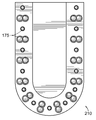
도 1은 청구된 발명의 장치의 일 실시예의 정면 사시도이다.
도 2는 청구된 발명의 장치의 실시예의 우측 사시도이다.
도 3은 힌지 뚜껑이 개방 위치에 있는 청구된 발명의 장치의 실시예의 전면 사시도이다.
도 4는 장치의 내부 전기적 구성요소들을 강조하는, 청구된 발명의 장치의 실시예의 상면 단면도이다.
도 5는 인간 사용자에 의해 사용 중에 있는 동안 청구된 발명의 장치의 실시예의 정면도이다.
도 6은 청구된 발명의 방법의 실시예의 단계들을 도시하는 흐름도이다.
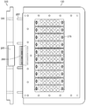
도 7은 청구된 발명의 또 다른 실시예의 상면도이다.
도 8은 실시예가 사용자의 신발의 살균을 가능하게 하기 위해 어떻게 뒤틀리는지를 도시하는 본 발명의 실시예의 상면도이다.
도 9는 신발의 힐을 근-IR 및 UV 광에 노출시키기 위한 다른 실시예의 상면도이다.
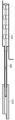
도 10은 청구된 발명의 완전히 연장된 실시예의 측면도이다.
도 11은 압축된 위치에 있는 청구된 발명의 실시예의 측면도이다.
도 12a는 좌측으로 배향된 손가락 또는 손가락들의 그룹을 수용하도록 구성된 본 발명의 다른 실시예의 평면도이다.
도 12b는 중앙에 있는 또는 중앙에 배향된 손가락 또는 손가락들의 그룹을 수용하도록 구성된 본 발명의 다른 실시예의 평면도이다.
도 12c는 우측으로 배향된 손가락 또는 손가락들의 그룹을 수용하도록 구성된 본 발명의 다른 실시예의 평면도이다.
도 13a는 본 발명의 실시예의 상면도이다.
도 13b는 본 발명의 실시예의 배면도이다.
도 13c는 본 발명의 실시예의 정면도이다.
도 13d는 본 발명의 실시예의 측면도이다.
도 14는 상승되어 디바이스 몸체의 나머지에서 분리된 뚜껑의 정면도이다.
도 15a는 손가락 이격 장치의 실시예의 측면도이다.
도 15b는 손가락 이격 장치의 실시예의 상면도이다.1 is a front perspective view of an embodiment of the apparatus of the claimed invention;
2 is a right-side perspective view of an embodiment of the apparatus of the claimed invention.
Figure 3 is a front perspective view of an embodiment of the claimed invention with the hinge lid in the open position.
4 is a top cross-sectional view of an embodiment of the claimed device of the invention, highlighting the internal electrical components of the device.
5 is a front view of an embodiment of an apparatus of the claimed invention while in use by a human user.
6 is a flow chart illustrating the steps of an embodiment of a method of the claimed invention.
7 is a top view of another embodiment of the claimed invention.
8 is a top view of an embodiment of the present invention showing how an embodiment is twisted to enable sterilization of a user's shoe.
Figure 9 is a top view of another embodiment for exposing the heel of the shoe to near-IR and UV light.
Figure 10 is a side view of a fully extended embodiment of the claimed invention.
11 is a side view of an embodiment of the claimed invention in a compressed position.
12A is a plan view of another embodiment of the present invention configured to accommodate a group of fingers or fingers oriented to the left.
12B is a plan view of another embodiment of the present invention configured to accommodate a centered or centrally oriented group of fingers or fingers.
12C is a top view of another embodiment of the present invention configured to accommodate a group of fingers or fingers oriented to the right.
13A is a top view of an embodiment of the present invention.
13B is a rear view of an embodiment of the present invention.
13C is a front view of an embodiment of the present invention.
13D is a side view of an embodiment of the present invention.
14 is a front view of the lid lifted up and separated from the rest of the device body;
15A is a side view of an embodiment of a finger spacing device.
15B is a top view of an embodiment of a finger spacing device.
본 발명의 바람직한 실시예들은 이제 도면들을 참조하여 설명될 것이다. 다양한 도면에서의 동일한 요소들은 동일한 참조 부호들로 식별된다.Preferred embodiments of the present invention will now be described with reference to the drawings. The same elements in the various figures are identified by the same reference numerals.
이제 본 발명의 각 실시예에 대해 상세하게 참조될 것이다. 그러한 실시예들은 본 발명의 설명으로 제공되며, 이는 그것으로 제한되도록 의도되지 않는다. 사실상 해당 기술분야의 통상의 기술자들은 본 명세서를 읽을 때 그리고 그것에 대해 다양한 변형 및 변경이 이루어질 수 있는 본 도면들을 볼 때 이해할 수 있다.Reference will now be made in detail to the embodiments of the present invention. Such embodiments are provided by way of explanation of the invention, and are not intended to be limiting thereof. In fact, those of ordinary skill in the art will appreciate from a reading of the present specification and with reference to the drawings in which various changes and modifications may be made thereto.
도 1은 청구된 발명의 일 실시예의 전체 배열을 도시한다. 디바이스(100)는 내측 표면(140), 외측 표면(135)을 가지며, 전력원(110)에 동작가능하게 연결된다. 디바이스는 조명 챔버(105)를 포함한다. 이러한 실시예에서, 조명 챔버(105)의 상부는 힌지 뚜껑(130)으로 구성된다. 힌지 뚜껑(130)은 디바이스(100)가 서비스되게 그리고 기둥들(115)이 조절될 수 있게 하기 위해 들어올려질 수 있다. 전력원(110)은, 다른 것들 중에서도, 기둥들(115) 내부에 포함되는 발광 다이오드들을 동작시킨다.Figure 1 shows a complete arrangement of an embodiment of the claimed invention. The
도 2는 외측 표면(135)에 부착되는 상태 발광 다이오드들(155)을 갖는 도 1에 도시된 청구된 발명의 실시예를 도시한다. 이들 상태 발광 다이오드들(155)은 적어도 디바이스가 전원이 켜 있는지, 클렌징 사이클에 있는지, 치료 사이클에 있는지, 또는 치료 준비가 되었는지를 나타낼 수 있다. 상태 발광 다이오드들(155)에 의해 주어지는 구체적 표시는 소정의 제조사의 선호에 기초하여 구성될 수 있다.Figure 2 shows an embodiment of the claimed invention shown in Figure 1 with status
도 3은 본 발명의 실시예의 다른 뷰를 도시한다. 이러한 실시예에서, 힌지 상부(130)는 개방 위치에 있어, 조명 챔버(105)의 내부를 노출시킨다. 이러한 뷰는 발광 다이오드들(175)을 전력원(110)에 동작가능하게 연결하기 위해 사용되는 배선들(180)을 도시한다. 이러한 실시예가 배선들(180)을 통해 기둥들(115)을 전력원(100)에 연결하지만, 기둥들(115)이 디바이스(100)의 전기 시스템들에 무선으로 연결되는 다른 실시예들이 존재함을 주의하자. 이러한 뷰는 또한 손가락 수용 영역(145), 뿐만 아니라 손가락 수용 영역(145)의 하부를 구성하는 구멍이 나 있는 격자(120)를 도시한다. 교체가능한 플레이트(150)가 또한 이러한 각도에서 보일 수 있다. 교체가능한 플레이트는 조명 챔버(105)의 하부 전체를 구성한다. 이러한 플레이트는 사용자가 치료 사이클을 완료한 후에 교환될 수 있다. 이는 디바이스(100)의 살균 프로세스를 돕거나 손상된 교체가능한 플레이트(150)의 교체를 도울 수 있다.Figure 3 shows another view of an embodiment of the present invention. In this embodiment, the
바람직한 실시예에서, 발광 다이오드들(175)은 약 870nm 및 약 930nm의 피크 파장들, ± 10°의 시야각, 각각의 파장들에 대해 각각, 약 50mW 및 약 35mW의 평균 전력, 및 약 500mW 및 약 350mW의 피크 전력을 갖는 발광 다이오드들의 쌍들을 포함한다. 이들 디바이스에 대한 정격 연속 동작 전류는 대략 100mA이며, 이는 평균 전력 출력을 전달한다. 피크 전력 출력을 달성하기 위해, 전류를 연속 준위보다 대략 10배로 증속 구동하는 것이 필요하며, 이는 약 1.0A 피크일 수 있다. 디바이스들의 안전한 동작 영역 내에 유지하기 위해, 이러한 피크 전류는 단지 100㎲의 최대 펄스 폭에 대해 유지될 수 있고 디바이스의 평균 전력 손실이 초과되지 않아야 한다. 이러한 실시예에서, 에너지 손실 및 치료받을 손가락들의 평균 크기를 고려한 후, 발광 다이오드들의 직경은 대략 5.0mm일 수 있고 발광 다이오드들은 치료받을 손가락의 표면으로부터 약 25.4mm에 배치될 것이다..In a preferred embodiment, the
다른 바람직한 실시예에서, 발광 다이오드들(175)의 어레이는 약 120mm x 약 34.5mm이어야 한다. 이러한 어레이는 알맞게 6개 발광 다이오드들(175)의 20행 또는 아마도 보다 유용하게, 6개의 10 갑절의 행을 형성한다. 도 3에 명백하게 도시되지 않지만, 디바이스(100)는 발광 다이오드들(175)의 어레이로 통합되는 UV 광을 방출할 수 있는 발광 다이오드들(175)을 가질 수 있다.In another preferred embodiment, the array of
도 4는 본 발명의 일 실시예의 구성을 예시한다. 이는 전력 공급부(110)의 실시예 부분이며, 변압기(160)가 도시된다. 나아가, 두 개의 인쇄가능한 회로 기판(165 및 170)이 도 6에 의해 예시된다. 이들 인쇄가능한 회로 기판(165 및 170)은 디바이스(100)가 사용자에 의해 제어될 수 있게 한다. 인쇄가능한 회로 기판들(165 및 170)은 또한 미리 결정된 치료 사이클들을 수행하는 방법에 대한 정보를 저장할 수 있는 메모리 및 프로세서를 포함하도록 구성될 수 있다. 예를 들어, 사용자가 10분의 2 사이클의 약 870nm 및 약 930nm의 조사를 받을 때, 이러한 메모리 및 프로세서는 그러한 사이클을 실행하는데 요구되는 단계들을 포함할 수 있다. 이는 사용자가 지정된 치료 사이클을 개시하기 위해 단지 하나의 버튼만 누를 수 있게 할 수 있다.4 illustrates a configuration of an embodiment of the present invention. This is an embodiment of the
바람직한 실시예에서, 인쇄가능한 회로 기판들은 전력 공급 기판 및 타이머 기판을 포함한다. 이는 청구된 발명의 장치를 미리 결정된 시간량 이후 자동으로 전원이 꺼질 수 있게 할 수 있다. 전력 공급 기판은 제어 회로에 조정된 12V의 직류 전압을 그리고 발광 다이오드의 체인들을 위한 전원에 비조정된 42V의 직류 전압 공급을 제공할 것이며, 이는 이전에 제시된 바와 같이 정전류원들로 조정될 것이다. 나아가, 대략 615Hz의 주파수 및 100㎲의 펄스 폭의 발광 다이오드들 체인들의 펄싱 온 및 오프 및 카운트다운 타이머를 제공하기 위한 별개의 타이머 기판이 존재할 것이다. 이러한 시스템을 이용하면, 발광 다이오드들(175)의 전류는 펄스 조정을 제공하기 위해 게이트 온 및 오프될 수 있는 아날로그 전압으로 설정될 수 있다. 전체 직류 공급부는 더 이상 타이트한 전압 조정을 필요로 하지 않을 수 있어, 복잡도 및 비용을 감소시키는데, 이는 아래에 제시될 바와 같이, 전류가 각 체인의 밑바탕에 있는 제어 회로에 의해 일정한 준위로 설정되기 때문이다.In a preferred embodiment, the printable circuit boards comprise a power supply substrate and a timer substrate. This allows the device of the claimed invention to be automatically powered off after a predetermined amount of time. The power supply substrate will provide a controlled DC voltage of 12V to the control circuit and a DC voltage supply of 42V unregulated to the power supply for the chains of light emitting diodes, which will be adjusted to constant current sources as previously presented. Further, there will be a separate timer substrate for providing pulsing on and off pulses and a countdown timer of chains of light emitting diodes at a frequency of approximately 615 Hz and a pulse width of 100 μs. With such a system, the current in the
또 다른 바람직한 실시예에서, 변압기(160)는 변압기(160)가 115V 입력(미국) 및 230V 입력(유럽)에 대해 구성될 수 있도록 일차 권선들 쌍을 갖는다. 여기서, 제1 인쇄 회로 기판(165) 및 제2 인쇄 회로 기판(175)은 동일한 풋프린트를 가지며 서로의 상부에 적층된다. 다른 실시예에서, 발광 다이오드들(175)의 제어를 위한 인쇄 회로 기판이 힌지 뚜껑(130)의 밑면에 부착되며, 이는 그것을 완전히 개방되고 상부 커버의 후부 상에 평평하게 놓일 수 있게 하기 위해 이중 힌지 배열을 가져, 치료 영역에의 완전한 접근을 제공한다.In another preferred embodiment, the
또 다른 실시예에서, 치료 영역을 위한 힌지 커버는 커버가 개방되어 있는 동안 디바이스가 동작하는 것을 방지하는 마이크로-스위치와 인터로크된다. UV 노출의 가능성 외에, NIR 발광 다이오드들(175)로부터의 방출은 가시 스펙트럼 밖에 있으나, 눈의 수정체는 이러한 파장을 여전히 투과할 것이고 이를 망막 상에 포커싱하며 이는 손상을 야기할 수 있다. 이것이 눈의 반응 밖에 있기 때문에, 광 출력의 세기에 대한 홍채의 반응이 존재하지 않고 눈 깜빡임 반응이 존재하지 않으며, 이로 인해 이러한 상태에서의 동작을 방지할 필요가 존재한다.In another embodiment, the hinge cover for the treatment area is interlocked with a micro-switch that prevents the device from operating while the cover is open. In addition to the possibility of UV exposure, the emission from the NIR
도 5는 사용 중에 있는 동안 본 발명의 표현을 도시한다. 발광 다이오드들(175) 및 기둥들(115)은 적어도 하나의 미리 결정된 파장의 광을 방출하고 있다. 이들 발광 다이오드(175) 및 기둥들(115)은 350nm 내지 약 1000nm의 파장을 갖는 광을 방출할 수 있다. 바람직한 실시예에서, 발광 다이오드들(175) 및 기둥들(115)은 약 383nm, 약 870nm, 및 약 930nm의 광을 방출한다. 복수의 발광 다이오드(175) 내 상이한 발광 다이오드들은 상이한 파장들의 광을 방출하도록 최적화될 수 있다. 기둥들(115)은 사용자의 손가락들(185)을 적절하게 고정 및 포함하도록 조절될 수 있다. 기둥들(115)은 조갑진균증의 보다 빠르고, 보다 강력한 치료를 야기할 치료 영역의 보다 완전한 노출을 제공할 것임이 예측됨을 주목하자. 바람직한 실시예에서, 발광 다이오드들(175)은 양자 모두 5mm의 직경을 갖는 관통-홀 유형이다. 다른 바람직한 실시예에서, 기둥들(115)은 직경이 8mm인 원기둥으로 구성된다. 그에 따라, 2mm 직경의 스테인리스 강 핀이 기둥(115)의 베이스에 사용되는 경우, 구멍이 나 있는 격자(120)가 기둥들(115)을 위치시키고 그것들을 수직으로 세워 고정하기 위해 사용될 수 있다. 이러한 배열은 사용자의 발톱들 및 손가락 사이 공간들에 대한 완전한 조명을 제공할 수 있다.Figure 5 shows the representation of the present invention while in use. The
도 6은 청구된 장치를 이용하는 방법의 실시예들 중 하나의 단계들을 예시한다. 이러한 방법은 사용자가 청구된 발명의 장치로 그들의 손가락들 중 적어도 하나를 배치시키는 단계(1100)로 시작된다.Figure 6 illustrates one of the steps of the method of using the claimed device. This method begins with
단계(1200)에서, 디바이스 전원이 켜진다. 단계(1300)는 분기할 수 있는 결과들을 갖는 질문을 포함한다.In
단계(1300)는 청구된 발명의 장치가 메모리 및 프로세서를 포함하는지를 고려한다. 만약 그렇다면, 청구된 발명의 장치는 이의 메모리의 콘텐츠을 실행하기 시작할 것이고 단계(1400)로 진행한다. 만약 그렇지 않다면, 개시된 방법의 이러한 실시예는 사용자에게 지정된 치료 프로그램에 따르기 위해 발광 다이오드들 및 기둥들을 수동으로 제어할 것을 요구한다.
단계(1400)에서, 발광 다이오드들 및 기둥들은 적어도 약 383nm, 870nm, 및 930nm의 파장들을 갖는 광으로 조명 챔버를 조명한다.In
단계(1500)에서, 프로세서는 지정된 치료 프로그램이 사용자의 손가락들을 자외선 광으로 조명할 것을 지시하는지를 확인하기 위해 메모리를 체크한다. 바람직한 실시예에서, 이러한 광은 약 383nm의 파장을 갖는다. 지정된 치료 프로그램이 사용자의 손가락을 조사할 것을 필요로 하는 경우, 단계(1550)가 실행되고 손가락이 조사될 것이다.At
지정된 프로그램이 자외선 광을 조사할 것을 필요로 하지 않는 경우, 방법은 단계(1600)로 진행할 것이다. 거기서, 방법은 치료 사이클이 반복될 필요가 있는지를 결정하기 위해 메모리를 체크한다. 만약 그렇다면, 발광 다이오드들 및 기둥들은 단계(1650)에서 미리 결정된 시간량 동안 턴 오프될 것이며, 그 다음 다시 단계(1400)로 진행될 것이다. 치료 사이클이 반복될 필요가 없는 경우, 실시예는 단계(1700)로 진행한다.If the designated program does not need to illuminate ultraviolet light, the method will proceed to step 1600. [ There, the method checks the memory to determine if the treatment cycle needs to be repeated. If so, the light emitting diodes and columns will be turned off for a predetermined amount of time at
단계(1700)에서 사용자의 손가락들은 조명 챔버에서 제거될 것이며, 그 다음 방법은 클렌징 사이클이 개시되어야 하는지 여부를 결정한다. 만약 그렇다면 실시예는 단계(1750)로 진행하고 클렌징 사이클이 개시된다. 만약 그렇지 않다면, 방법은 단계(1800)로 진행하고 디바이스 전원이 꺼진다. 방법의 일 실시예에서, 치료 사이클은 15분 동안 지속될 것이다.In
도 7 및 도 8은 상기 사용자의 신발에서 임의의 진균을 제거함으로써 사용자의 신발을 살균하도록 특화된 장치의 실시예를 도시한다. 발광 다이오드들(175)의 메커니즘은 그것이 청구된 발명의 장치의 앞서 언급된 실시예들에 있기 때문에 여기서 동일하다는 것을 주의하는 것이 중요하다. 중요한 차이는 살균 디바이스(200)에서는, 발광 다이오드들(175)이 정적 어레이로 있는 것이 아니라, 발광 다이오드들(175)이 스핀(spine)(190)으로부터 연장되는 실시예의 핑거들(finger)(215) 상에 위치된다는 것이다. 다른 바람직한 실시예에서, 각 핑거(215)는 중앙 스핀에 수직한 휴면 위치를 제공하기 위해 스핀(190)을 갖는 피벗점에 대한 90° 비틀림 스프링을 갖고 수지로 포팅(potting)되는 인쇄 회로 기판으로 구성된다. 이러한 메커니즘은 도 8에 도시된 바와 같이, 핑거들이 신발의 외측 경계들까지 연장될 수 있게 한다.FIGS. 7 and 8 illustrate an embodiment of a device specialized to sterilize a user's shoe by removing any fungus from the user's shoe. It is important to note that the mechanism of the light-emitting
상향 및 하향 양자로 그리고 각 쌍 사이를 향하는 6개의(3쌍의) NIR 발광 다이오드들(175)이 존재하는 각 핑거에, 중앙에 장착되는 하나의 UV 발광 다이오드(175)가 존재한다. 상측 및 하측 발광 다이오드들은 그것들이 인쇄가능한 회로 기판에 장착될 수 있게 하기 위해 스태거링될 필요가 있을 것이다. 통상적인 신발의 형상을 수용하기 위해, 바람직하게는 중앙 스핀(190)의 어느 하나의 측 상에 미러링되는, 적어도 세 개의 상이한 길이의 핑거(215)가 존재한다. 이러한 방식으로 조사되는 신발의 앞, 또는 발 부분(225)과 함께, 신발의 힐 부분(220)이 또한 노출을 필요로 할 것이다.There is one centrally mounted UV
도 7에서, 살균 디바이스(200)의 힐 부분(220)에 위치되는 핑거들(215)이 존재한다. 제시된 두 개의 구성은 핑거들(215)이 신발류의 물품에 적절한 조명 커버리지를 제공하도록 배열될 수 있는 방식을 실증한다. 두 개의 구성은 가능한 구성들을 예시하는 것으로 의도되고 해당 기술분야의 통상의 기술자들은 핑거들(215)의 배치의 다양한 변경이 존재함을 인식할 것이다.In FIG. 7, there are
힐 부분(220) 위에 "펼쳐지기" 위해 피벗점에 대한 비틀림 스프링을 채용하는 다수의 핑거(215)가 존재할 수 있다. 추가적으로, 핑거들(215)은 힐 부분(220) 및 발 부분(225)으로부터 힐 부분(220)을 향해 지향될 수 있고 그렇게 함으로써 힐 부분(220)에 조명된 커버리지를 제공할 수 있다. 핑거들(215)은, 도 8에 도시된 바와 같이, 신발류의 물품에 완전한 커버리지를 제공하도록 배열될 수 있거나, 또는 단지 발 부분(225) 상에만 존재할 수 있다. 단지 발 부분(225) 상에 존재하는 경우, 살균 디바이스는 조명된 힐 컵(heel cup)(도 9 참조)을 더 채용할 수 있다. 그러나, 힐 컵은 설명된 바와 같이 또한 힐 부분(220) 상에도 핑거들(215)과 함께 이용될 수 있다.There may be a plurality of
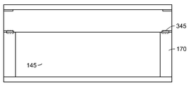
이제 도 9를 참조하면, 사용자의 신발의 힐 부분을 클렌징 및 살균하도록 의도된 디바이스의 특정 실시예의 힐 컵 실시예가 존재한다. 핑거들(215)(도 8 참조)과 같이, 수지로 포팅된 인쇄가능한 회로 기판이 힐 컵 같은 구조에 포함된다. 이러한 인쇄가능한 회로 기판은 그것을 신발의 뒤쪽 가까이에 고정하기 위해 스프링 작동식 샤프트 상에 장착된다.Referring now to FIG. 9, there is a heel cup embodiment of a particular embodiment of a device intended to cleanse and sanitize the heel portion of a user's shoe. Like the fingers 215 (see FIG. 8), a resin-printed, printable circuit board is included in the heel cup-like structure. This printable circuit board is mounted on a spring-actuated shaft to secure it near the back of the shoe.
도 10 및 도 11은 중앙 샤프트(195)의 동작을 도시한다. 이러한 중앙 샤프트(195)는 다음 두 기능을 제공한다: 핑거들의 조절, 및 힐 플레이트의 지지 및 위치 지정. 일 실시예에서, 핑거들을 스핀(190)에 근접하게 가져오는데 요구되는 이동을 수용하기 위해, 중앙 샤프트(195)는 대략 5mm만큼 앞으로 이동할 필요가 있다.Figs. 10 and 11 show the operation of the
도 10 및 도 11에 도시된 실시예에 대해, 핑거들은 두 개의 얇은 스틸 플레이트 사이에 장착된다. 두 개 중 하측은 디바이스에 프런트 스톱(front stop)을 제공하기 위해 프런트 엔드(front end)에서 약간 연장된다. 두 개의 수직 플레이트, 즉 앞쪽 및 뒤쪽은 디바이스의 길이를 설정하고 중앙 샤프트(195)의 위치를 허용한다. 상측 플레이트는 디바이스가 제거를 위해 압축될 때 고정점으로서의 역할을 하기 위해 90°로 구부려진다. 그것은 요구되는 조절을 수용하기 위해 바람직하게는 두 개의 압축 스프링을 필요로 할 것이다. 스페이서 및 스프링은 버트들(butts)을 뒤쪽 수직 플레이트 가까이 위로 가이딩하고 중앙 샤프트(195)의 뒤쪽 상의 스냅 스프링은 힐 플레이트가 스프링 압력을 받아 분리되는 것을 방지한다. 힐 플레이트(210)는 중앙 샤프트(195) 상에서 앞으로 슬라이딩 할 수 있고 스프링들을 압축할 것이며, 이는 힐 플레이트(210)를 신발의 뒤쪽 가까이에 고정할 것이다. 이러한 스테이지에서, 중앙 샤프트(195)는 신발 내 핑거들(215)의 위치에 어떠한 영향도 주지 않을 것이며, 이는 그것들 자체의 위치를 찾을 것이다.For the embodiment shown in Figures 10 and 11, the fingers are mounted between two thin steel plates. The lower of the two slightly extends from the front end to provide a front stop to the device. The two vertical plates, front and rear, set the length of the device and allow positioning of the
디바이스가 제거될 때, 힐 플레이트(210)는 더 앞으로 밀어지고 중앙 샤프트(195) 상의 제2 스냅 링 가까이에 밀 것이다. 이는 제거의 용이함을 위해 중앙 샤프트(195)를 앞으로 밀고 핑거들을 스핀(190)으로 비스듬히 움직일 것이다.When the device is removed, the
도 12a 내지 도 12c는 본 발명의 다른 가능한 실시예를 실증한다. 적어도 두 개의 지지 기둥(270)에 의해 지지되고 수 커넥터(240)를 통해 바람직하게는 디바이스 몸체 상에 존재하는 호환가능한 암 커넥터에 결합되는 힌지 및/또는 착탈가능 뚜껑(130)을 갖는 디바이스(100)의 실시예의 평면도가 도시된다. 뚜껑(130)의 밑면 상에 어레이(275)로 배열되는 복수의 LED(175)가 있다. 복수의 LED(175)는 바람직하게는 본 출원에서 이전에 설명된 바와 동작 파장이 일치되나, 다른 파장들 또는 파장들의 조합들이 고려될 수 있다. 어레이(275)는 그에 따라 LED들이 고정된 경로를 따라 일체로 회전하게 하는, 전체로서의 어레이(275)의 회전을 가능하게 하는 회전가능 바들(250)에 의해, 적어도 하나의 측방향 에지, 바람직하게는 두 개의 에지를 따라 경계지어 진다. 나아가, 뚜껑(130)의 밑면을 따라 내장되고/되거나 그것으로부터 돌출하는 복수의 UV LED(230)가 있다. UV LED들(230)은 바람직하게는 어레이(275)의 부분을 형성하지 않고 몇몇 실시예에서는 존재하지 않을 수 있다.Figures 12A through 12C demonstrate another possible embodiment of the present invention. A
뚜껑(130)의 외측 표면 상에 회전가능 메커니즘(260)을 통해 어레이(275)에 결합되는 다이얼(220)이 존재한다. 다이얼(220)은 도 12a, 도 12b, 및 도 12c의 각각에 도시된 바와 같이 적어도 세 개의 상이한 위치 사이에서 자유롭게 회전하도록 구성된다. 다이얼(220)은, 회전될 때, 회전가능 메커니즘(260)의 회전을 야기하며, 이는 차례로, 전체로서의 어레이(275)의 배열 또는 배향의 회전을 야기한다.There is a
어레이(275)의 회전은 다수의 이점을 제공한다. 예를 들어, 다이얼(220)을 조작함으로써 사용자의 발 또는 다른 부속기관에 의해 형성되는 특정 각도로 어레이(275)를 보다 근접하게 정렬할 수 있다. 이는 좌측 및 우측 발 양자에 대한 모든 손가락의 포괄적인 커버리지를 가능하게 한다. 그에 따라, 사용자는 그들의 좌측 발을 치료하고(도 12a 참조) 그 다음 그들의 우측 발을 치료하도록(도 12c 참조) 어레이(275)를 배향시키기를 바랄 수 있다. 배향들의 각각은 모든 손가락이 광의 중첩 치료를 받고 부속기관 또는 손가락이 곤란한 또는 불편한 각도로 삽입될 필요가 없음을 보장한다. 손들 또는 각각의 손가락들과 관련될 수 있는 다른 보다 중립의 배치들에서 중앙 또는 중립 위치가 요구될 수 있다(도 12b 참조). 어레이(275)를 그들의 부속기관들의 각도에 맞추도록 배향시키기 위한 유연성을 가지지 않는다면, 부속기관 그 자체는 불편할 수 있는 각도들로 배향되어야 하고 디바이스 그 자체의 구성에 의해 더 구속될 수 있다.The rotation of the
이제 도 13a 내지 도 13d를 참조하면, 본 발명의 실시예의 다양한 뷰가 존재한다. 뷰들은 상면(도 13a), 정면(도 13c), 측면(도 13d), 및 배면(도 13b)으로부터 디바이스(100)를 도시한다. Referring now to Figures 13A-13D, there are various views of an embodiment of the present invention. The views show the
도 13a에, 디바이스의 상면도가 존재한다. 디바이스의 상부는 뚜껑(130)의 밑면 상에 포함되는 광 어레이(275)의 회전을 가능하게 하는 다이얼(260)을 갖는다. 뚜껑(130)은 나머지 디바이스 구조, 뿐만 아니라 지지 기둥들(170)에 의해 지지된다. 지지 기둥들(170)은 디바이스가 사용 중에 있는 동안 뚜껑(130)의 위치를 고정하기 위해 결합 메커니즘(345) 이를테면 고 강도(예를 들어 네오디뮴) 자석을 갖는다.In Fig. 13A, there is a top view of the device. The top of the device has a
광 어레이(275)는 뚜껑(130)에 회전가능하게 결합된다. 다이얼(260)은 광 어레이가 사용자에 의해 요구되는 배향에 따르도록 지향될 수 있게 한다. 어레이(275)는 뚜껑 표면의 밑면으로부터 돌출하거나 내장되는 복수의 UV LED(230)에 의해 양측에 접해진다. 광 어레이(275)는, 그에 반해, 본 출원에 이전에 설명된 것들과 일치하는 파장들을 방출하는 광들을 갖는다. 몇몇 사례에서, 아래에 더 설명될 바와 같이, 뚜껑(130)은 디바이스 몸체에 결합될 LED들의 상이한 세트와 상이한 어레이를 허용하기 위해 제거될 수 있다.The
정면에서 보이는 바와 같이, 지지 기둥들(170)은 손가락(들) 또는 부속기관이 손가락/부속기관 수용 영역(145)으로 자유롭게 삽입될 수 있게 하는 "개방 컨셉"을 정의한다. 이러한 비-제한적 개방은 사용자가 그들의 손가락/부속기관의 배향을 조절할 수 있게 하는 한편 또한 LED들에 의해 발생되는 임의의 잔열을 소산시키는 것을 돕기 위해 적절한 기류를 제공한다. 나아가, 도 13d에서 개방 컨셉이 측면으로부터 도시된다. 그에 따라, 손가락 수용 영역(145)은 비록 지지 기둥들(170)에 대해서 일지라도, 디바이스의 세 개의 측을 따라, 실질적으로 개방된다. 나머지 폐쇄된 측은 바람직하게는 디바이스의 배면이다.
도 13d에 또한 상태 LED들(155)이 도시된다. 본 출원에 설명된 바와 같이 또는 그 외 본 발명의 범위하에 포함되는 임의의 수의 동작 상태가 존재할 수 있다. 예를 들어, 도 13d에 도시된 상태 LED들은 "실행" 사이클, "클린" 사이클, "시한" 사이클, 및 "주파수" 사이클에 대응한다. 사용 중인 디바이스 상에 도시되는 사이클들 또는 셋팅들은 도면들에서의 본 출원에 반영되는 바와 동일 또는 상이할 수 있다.
디바이스의 이면은 전력 입력부(125) 뿐만 아니라 전력 출력부(127)를 포함할 수 있다. 전력 입력부(125)는 전력원(110)(도 2 참조)의 연결을 허용한다. 전력 출력부(127)는 도 15a 및 도 15b에 도시된 바와 같이 손가락 이격 메커니즘(360)에 전기 전력을 공급하기 위해 USB 또는 다른 적절한 연결을 제공할 수 있다.The back surface of the device may include a
도 14에서, 뚜껑(130)은, 도 13a에 설명된 바와 같이, 분리가능할 수 있다. 그러한 분리가능 뚜껑(130)의 목적은 디바이스의 추가 클렌징을 제공할 뿐만 아니라 부분들의 변경 및/또는 교체를 제공할 수 있다. 예를 들어, 도시된 바와 같은 뚜껑(130)은 몰렉스(Molex) 또는 다른 적절한 유형의 연결일 수 있는 암 커넥터(265)에 결합된다. 수 커넥터(240)는 암 커넥터(265) 내에 맞고 그에 의해 수용된다. 수/암 커넥터들이 제 위치로 가이딩될 때, 고정 핀들(280)이 또한 디바이스 몸체에 고정된다.In Fig. 14, the
고정 핀들(280)은 사용 동안 뚜껑(130)에 강성을 제공하고 뚜껑(130)이 어떠한 한 방향으로도 회전되는 것을 방지하고 그렇게 함으로써 사용, 보관, 수송 등 동안 뚜껑(130) 또는 커넥터들에 대한 해를 방지한다. 고정 메커니즘들(280)은 리셉터클(285)에 맞추도록 구성되는 스테인리스 강 또는 다른 금속, 플라스틱, 고무, 및 기타 맞춤 못일 수 있다. 각 고정 메커니즘(280)은 하나의 리셉터클(285)에 맞추도록 설계되고 몇몇 실시예에서 다수의 고정 메커니즘이 단일 리셉터클 내에 존재할 수 있다.The locking pins 280 provide rigidity to the
실제는, 뚜껑(130)이 어레이(275)가 상이한, 그러나 유사한 어레이(275)로 변경될 수 있게 하기 위해 제거될 수 있다. 예를 들어, 상이한 피부 유형들을 위한 치료들을 제공하기 위해, 그것은 그러한 맞춤화 특징을 갖는 디바이스(100)를 갖는 것에 유리할 수 있다. 보다 밝은 피부 톤들보다 높은 농도의 멜라닌을 갖는, 보다 어두운 피보 톤들은 광 흡수의 증가를 야기할 것이고 그렇게 함으로써 적용된 치료의 침투의 정도에 불리하게 영향을 미칠 것이다. 뚜껑(130) 및 후속하여 어레이(275)를 다른 보다 적절한 어레이(275) 및 관련 광 파장들로 교체함으로써, 그것은 각각의 LED를 변경할 필요 없이 적절한 치료를 가능하게 할 수 있을 것이다.In practice, the
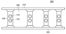
이제 도 15a 및 도 15b를 참조하면, 본 출원에 설명된 본 발명의 실시예들과 사용될 수 있는 손가락 이격 메커니즘(360)이 존재한다. 몇몇 사례에서, 손가락 이격 메커니즘(360)은 디바이스(100) 그 자체를 필요로 하지 않고 이용될 수 있다. 손가락 이격 메커니즘(360)은 일반적으로 제1 표면(310), 제2 표면(320), 스페이서들(330) 내에 포함되는 LED들(175)을 갖는 적어도 두 개의 스페이서(330)를 갖는다. 나아가, 케이블(350) 및 배선(340)의 전력은 디바이스 및 LED들(175) 간 전자 통신을 가능하게 한다.Referring now to FIGS. 15A and 15B, there is a
손가락 이격 메커니즘(360)은 이에 한정되는 것은 아니지만 플라스틱, 고무, 발포 고무, 및 실리콘 또는 이들의 임의의 조합을 포함하는 임의의 수의 메커니즘으로 구성될 수 있다. 제1 표면(310), 제2 표면(320), 및 스페이서들(330)은 각각 동일한 또는 상이한 물질로 구성될 수 있다. 치료(손가락들 간 간격으로 전달될 치료) 동안 광의 정확한 투과를 허용하기 위해, 선택되는 물질이 모든 가시 파장의 광의 투과를 가능하게 하고 가시 스펙트럼의 어느 하나의 측 상에서 적어도 500nm를 향하여 연장되는 양호한 광학적 선명도를 보인다는 것이 중요하다.The
바람직하게는 제1 표면(310) 및 제2 표면(320)은 일반적으로 서로에 관해 평행한 방식으로 위치된다. 스페이서들(330)은 바람직하게는 그것들 사이에 위치되고 제1 표면(310) 및 제2 표면(320)의 각각에 결합된다. 스페이서들(330)의 각각 사이에 사이 공간(390)이 존재한다. 바람직하게는, 적어도 하나의 그리고 보다 바람직하게는 적어도 두 개의 LED(175)가 스페이서들(330)의 각각 내에 배치된다. 두 개의 LED(175)가 이용될 때, LED들은 각각, 약 870nm 및 약 940nm의 광을 방출한다.Preferably, the
LED들(175)은 바람직하게는 제1 표면(310) 또는 제2 표면(320) 중 어느 하나에 내장되는 배선(340)과 직렬 연결로 배선(340)을 통해 결합된다. 나아가, 손가락 이격 메커니즘(360)의 동작을 위한 전기 전력이 케이블(350)의 전력을 통해 공급된다. 케이블(350)의 전력은 디바이스 또는 전력원(110)(도 2 참조)에 결합될 수 있다.The
손가락 이격 메커니즘(360)은 사용자가 두 개 보다는 메커니즘들 중 단지 하나를 필요로 할 수 있다는 점에서 양면성이도록 의도된다. 사용시, 손가락 이격 메커니즘(360)은 예를 들어, 우측 발, 좌측 발, 좌측 손, 또는 우측 손에 따라 맞춰질 수 있다. 사용되는 경우 바디의 우측 상에 대응하는 부속기관에 대해 사용될 하나의 측(즉 좌측)에 대해 메커니즘은 간단히 역전되어야 한다. 그에 따라, 도 15a에 도시된 뷰와 비교할 때 제1 표면(310)은 하부에 존재할 수 있을 것이고 제2 표면(320)은 상부에 존재한다. 나아가, 메커니즘은 그것이 치료를 위해 디바이스에 배치되기 전 부속기관 상에 배치될 수 있다.The
본 발명이 소정의 특정도로 설명되었지만, 본 설명은 단지 예로서 이루어졌고 구성의 세부사항들 및 부분들의 배열의 많은 변경이 본 발명의 사상 및 범위를 벗어나지 않고 재분류될 수 있다는 것이 이해되어야 한다.Although the present invention has been described in some specific ways, it is to be understood that this description is made only by way of example and that many changes in the details of construction and arrangement of parts may be reclassified without departing from the spirit and scope of the invention.
Claims (28)
전력원;
상기 전력원에 동작가능하게 연결되는 적어도 하나의 발광 다이오드로서,
상기 적어도 하나의 발광 다이오드는 약 870nm 내지 약 930nm의 파장들의 광을 방출하는, 적어도 하나의 발광 다이오드; 및
내측 및 외측 표면, 및 손가락 수용 영역을 갖는 챔버로서,
상기 손가락 수용 영역은 적어도 하부 표면을 갖고,
적어도 하나의 발광 다이오드는 원하는 경우 상기 적어도 하나의 발광 다이오드가 상기 손가락 수용 영역을 조명할 수 있게 하는 배향으로, 상기 챔버의 내측 표면에 고정되는, 상기 챔버를 포함하는, 디바이스.A therapeutic device for treating nails, nail bottoms, and surrounding tissue,
Power source;
At least one light emitting diode operatively connected to the power source,
The at least one light emitting diode emitting light of wavelengths from about 870 nm to about 930 nm; And
A chamber having an inner and an outer surface, and a finger receiving area,
Wherein the finger receiving area has at least a lower surface,
Wherein the at least one light emitting diode is secured to an inner surface of the chamber with an orientation that allows the at least one light emitting diode to illuminate the finger receiving area if desired.
상기 발광 다이오드는 상기 챔버의 상기 내측 표면에 부착되며, 그리고 상기 발광 다이오드는 상기 발광 다이오드가 자외선 광으로 상기 챔버의 상기 손가락 수용 영역을 조명할 수 있게 하는 배향으로 고정되는, 디바이스.The light emitting diode of claim 1, further comprising at least one additional light emitting diode, wherein the light emitting diode is capable of generating light having a wavelength of about 383 nm;
Wherein the light emitting diode is attached to the inner surface of the chamber and the light emitting diode is fixed in an orientation that allows the light emitting diode to illuminate the finger receiving area of the chamber with ultraviolet light.
상기 기둥들은 적어도 하나의 발광 다이오드를 포함하며, 그리고
상기 기둥들은 그것들이 사용자의 손가락들 사이에 위치될 수 있도록 상기 손가락 수용 영역의 상기 하부 표면으로 삽입될 수 있는, 디바이스.The power supply of claim 1, further comprising adjustable columns operatively connected to the power source,
The columns comprising at least one light emitting diode, and
The posts being insertable into the lower surface of the finger receiving area such that they can be positioned between the user's fingers.
상기 발광 다이오드들은 각각, 약 870nm 내지 약 930nm의 파장들의 광을 방출하는, 디바이스.The light emitting diode of claim 1, wherein at least two light emitting diodes are present,
Wherein the light emitting diodes emit light of wavelengths from about 870 nm to about 930 nm, respectively.
전력원;
상기 전력원에 동작가능하게 연결되는 복수의 발광 다이오드로서,
상기 발광 다이오드들은 약 870nm 내지 약 930nm의 파장들의 광을 방출하는, 상기 복수의 발광 다이오드;
약 383nm의 파장의 광을 발생시킬 수 있는 적어도 하나의 자외선 광;
내측 및 외측 표면, 및 손가락 수용 영역을 갖는 챔버로서,
상기 손가락 수용 영역은 적어도 하부 표면을 갖고,
상기 손가락 수용 영역은 사용자가 상기 챔버 내부에 적어도 하나의 손가락을 편안하게 배치시키기에 충분히 큰, 상기 챔버; 및
잠재적 사용자의 손가락들의 상이한 크기를 수용하기 위해 기둥들 간 공간을 조절하기 위한 조절 메커니즘을 포함하는, 디바이스.A therapeutic device for treating nails, nail bottoms, and surrounding tissue,
Power source;
A plurality of light emitting diodes operatively connected to the power source,
Wherein the light emitting diodes emit light of wavelengths from about 870 nm to about 930 nm;
At least one ultraviolet light capable of generating light having a wavelength of about 383 nm;
A chamber having an inner and an outer surface, and a finger receiving area,
Wherein the finger receiving area has at least a lower surface,
The finger receiving area being large enough for a user to comfortably place at least one finger inside the chamber; And
And an adjustment mechanism for adjusting the spacing between the pillars to accommodate different sizes of potential user fingers.
a) 치료 디바이스로 치료 영역을 조사하는 단계로서, 상기 치료 디바이스는,
전력원,
상기 전력원에 동작가능하게 연결되는 복수의 발광 다이오드로서,
상기 발광 다이오드들은 약 870nm 내지 약 930nm의 파장들의 광을 방출하는, 상기 복수의 발광 다이오드, 및
약 383nm의 파장의 광을 발생시킬 수 있는 적어도 하나의 자외선 발광 다이오드를 포함하는, 상기 치료 영역을 조사하는 단계;
b) 상기 치료 영역이 제1 미리 결정된 시간량 동안 상기 치료 디바이스에 의해 조사되게 유지할 수 있게 하는 단계; 및
c) 약 7일마다 한 번씩 제2 미리 결정된 시간량 동안 단계들 a) 및 b)를 반복하는 단계를 포함하는, 방법.A method for preventing and treating nails and skin fungi,
a) examining a treatment area with a treatment device,
Power source,
A plurality of light emitting diodes operatively connected to the power source,
Wherein the light emitting diodes emit light of wavelengths from about 870 nm to about 930 nm, the plurality of light emitting diodes, and
Irradiating the treatment area comprising at least one ultraviolet light emitting diode capable of generating light at a wavelength of about 383 nm;
b) enabling the treatment area to be maintained by the treatment device for a first predetermined amount of time; And
c) repeating steps a) and b) for a second predetermined amount of time once every about 7 days.
(a) 적어도 하나의 손가락을 챔버 내부에 배치시키는 단계로서,
상기 챔버는 내측 표면, 외측 표면, 및 손가락 수용 영역을 갖되,
상기 챔버는 적어도 두 개의 발광 다이오드를 갖되, 상기 적어도 두 개의 발광 다이오드 중 적어도 하나는 약 383nm의 파장을 갖는 광을 발생시킬 수 있고 상기 챔버의 상기 내측 표면에 고정되며,
상기 손가락 수용 영역은 상부 및 하부 표면을 갖는, 상기 적어도 하나의 손가락을 챔버 내부에 배치시키는 단계;
(b) 약 870nm 내지 약 930nm의 파장들의 상기 광이 발생되도록 상기 챔버에 전원을 공급하는 단계;
(c) 상기 손가락이 제1 미리 결정된 시간량 동안 상기 챔버에 유지될 수 있게 하는 단계; 및
(d) 일주에 한 번씩 제2 미리 결정된 시간량의 지속기간 동안 단계들 (a) 내지 (c)를 반복하는 단계를 포함하는, 방법.A method for preventing and treating nails and skin fungi,
(a) disposing at least one finger inside the chamber,
The chamber has an inner surface, an outer surface, and a finger receiving area,
Wherein the chamber has at least two light emitting diodes, at least one of the at least two light emitting diodes being capable of generating light having a wavelength of about 383 nm and being fixed to the inner surface of the chamber,
Disposing the at least one finger inside the chamber, the finger receiving area having upper and lower surfaces;
(b) powering the chamber to generate the light of wavelengths from about 870 nm to about 930 nm;
(c) allowing the finger to be held in the chamber for a first predetermined amount of time; And
(d) repeating steps (a) to (c) once per week for a duration of a second predetermined amount of time.
클렌징 사이클이 치료 사이클 후에 개시되고,
상기 클렌징 사이클은 미리 결정된 시간량 동안 약 383nm의 파장의 광으로 상기 챔버를 조사하는 단계로 구성되는, 방법.16. The method of claim 15, further comprising the step (e)
A cleansing cycle is initiated after the treatment cycle,
Wherein the cleansing cycle comprises irradiating the chamber with light at a wavelength of about 383 nm for a predetermined amount of time.
만약 그렇다면, 상기 방법은 상기 디바이스가 상기 메모리의 콘텐츠에 따라 지정된 상기 치료 사이클들을 자동으로 개시 및 종료하는 단계를 더 포함하는, 방법.16. The method of claim 15, wherein the method considers whether the device comprises a processor and a memory,
If so, the method further comprises the device automatically initiating and terminating the therapy cycles designated in accordance with the contents of the memory.
전력원;
상기 전력원에 동작가능하게 연결되는 적어도 하나의 발광 다이오드로서,
상기 적어도 하나의 발광 다이오드는 약 870nm 내지 약 930nm의 파장들의 광을 방출하는, 적어도 하나의 발광 다이오드;
정면 및 원위 단부를 갖는 스핀(spine);
상부 및 하부 표면 및 정면 및 원위 단부를 갖는 복수의 핑거(finger)로서,
상기 핑거의 원위 단부는 상기 스핀에 힌지식으로 부착되고,
상기 적어도 하나의 발광 다이오드가 핑거에 부착되는, 상기 복수의 핑거를 포함하는, 살균 디바이스.As a sterilizing device,
Power source;
At least one light emitting diode operatively connected to the power source,
The at least one light emitting diode emitting light of wavelengths from about 870 nm to about 930 nm;
A spine having a frontal and a distal end;
A plurality of fingers having upper and lower surfaces and a frontal and distal end,
The distal end of the finger is hingedly attached to the spin,
Wherein the at least one light emitting diode is attached to a finger.
상기 힐 플레이트는 적어도 두 개의 발광 다이오드를 포함하되,
제1 발광 다이오드는 약 870nm 및 약 930nm의 파장들을 갖는 광을 방출하도록 구성되고,
제2 발광 다이오드는 약 383nm의 파장을 갖는 광을 방출하도록 구성되며,
상기 적어도 두 개의 발광 다이오드는 상기 힐 플레이트 전체에 걸쳐 고르게 이격되는, 살균 디바이스.20. The apparatus of claim 19, further comprising a heel plate having a flat front and a rounded distal end, the heel plate being connected to the distal end of the spin,
The heel plate includes at least two light emitting diodes,
The first light emitting diode is configured to emit light having wavelengths of about 870 nm and about 930 nm,
The second light emitting diode is configured to emit light having a wavelength of about 383 nm,
Wherein the at least two light emitting diodes are evenly spaced across the heel plate.
상기 제1 중공 원기둥은 상기 제1 중공 원기둥이 상기 제2 중공 원기둥 내에 배치될 수 있도록 상기 제2 중공 원기둥보다 작은 직경을 갖고,
상기 압축 스프링은 두 개의 상기 중공 원기둥이 연장된 위치에 놓이나 적절한 힘의 인가시, 상기 제1 중공 원기둥 및 상기 제2 중공 원기둥이 보다 작은 환경에 배치되게 수용하기 위해 압축하도록 상기 제1 중공 원기둥 및 제2 중공 원기둥 사이에 삽입되는, 살균 디바이스.21. The method of claim 20, wherein the spin comprises a first hollow cylinder, a second hollow cylinder, and a compression spring,
Wherein the first hollow cylinder has a smaller diameter than the second hollow cylinder so that the first hollow cylinder can be disposed in the second hollow cylinder,
Wherein the compression spring is configured to compress the first hollow cylindrical body and the second hollow cylindrical body to compress the first hollow cylindrical body and the second hollow cylindrical body to be accommodated in a smaller environment when the two hollow cylindrical bodies are in their extended positions, And a second hollow cylinder.
치료 디바이스로서,
전력원;
상기 전력원에 동작가능하게 연결되는 적어도 하나의 발광 다이오드로서,
상기 적어도 하나의 발광 다이오드는 약 870nm 및 약 930nm의 파장들의 광을 방출하는, 적어도 하나의 발광 다이오드; 및
내측 및 외측 표면, 및 손가락 수용 영역을 갖는 챔버로서,
상기 손가락 수용 영역은 적어도 하부 표면을 갖고,
적어도 하나의 발광 다이오드는 원하는 경우 상기 적어도 하나의 발광 다이오드가 상기 손가락 수용 영역을 조명할 수 있게 하는 배향으로, 상기 챔버의 내측 표면에 고정되는, 상기 챔버를 포함하는, 치료 디바이스; 및
살균 디바이스로서,
전력원,
상기 전력원에 동작가능하게 연결되는 적어도 하나의 발광 다이오드로서,
상기 발광 다이오드들은 약 870nm 내지 약 930nm의 파장들의 광을 방출하는, 상기 적어도 하나의 발광 다이오드,
정면 및 원위 단부를 갖는 스핀,
상부 및 하부 표면 및 정면 및 원위 단부를 갖는 복수의 핑거로서,
상기 핑거의 원위 단부는 상기 스핀에 힌지식으로 부착되며, 그리고
상기 적어도 하나의 발광 다이오드가 핑거에 부착되는, 상기 복수의 핑거를 포함하는, 살균 디바이스를 포함하는, 치료 키트.As a treatment kit for treating fungi,
As a therapeutic device,
Power source;
At least one light emitting diode operatively connected to the power source,
The at least one light emitting diode emitting light at wavelengths of about 870 nm and about 930 nm; And
A chamber having an inner and an outer surface, and a finger receiving area,
Wherein the finger receiving area has at least a lower surface,
Wherein the at least one light emitting diode is secured to an inner surface of the chamber with an orientation that allows the at least one light emitting diode to illuminate the finger receiving area if desired. And
As a sterilizing device,
Power source,
At least one light emitting diode operatively connected to the power source,
Wherein the light emitting diodes emit light of wavelengths from about 870 nm to about 930 nm, the at least one light emitting diode,
Spin with front and distal ends,
A plurality of fingers having upper and lower surfaces and a frontal and distal end,
The distal end of the finger is hingedly attached to the spin, and
Wherein the at least one light emitting diode is attached to a finger, the sterilizing device comprising a plurality of fingers.
평평한 정면 및 라운딩된 원위 단부를 갖고, 상기 스핀의 상기 원위 단부에 연결되는 힐 플레이트로서,
상기 힐 플레이트는 적어도 두 개의 발광 다이오드를 포함하는, 상기 힐 플레이트,
약 870nm 내지 약 930nm의 파장들을 갖는 광을 방출하도록 구성되는 제1 발광 다이오드, 및
약 383nm의 파장을 갖는 광을 방출하도록 구성되는 제2 발광 다이오드를 더 포함하는, 치료 키트.23. The device of claim 22,
A heel plate having a flat front and a rounded distal end and connected to the distal end of the spin,
Wherein the heel plate comprises at least two light emitting diodes,
A first light emitting diode configured to emit light having wavelengths from about 870 nm to about 930 nm, and
Further comprising a second light emitting diode configured to emit light having a wavelength of about 383 nm.
제1 표면이 거리만큼 제2 표면과 분리된 상기 제1 표면 및 상기 제2 표면;
상기 제1 표면 및 상기 제2 표면 사이에 위치되고 그것들의 각각에 결합되는 적어도 두 개의 스페이서로서,
상기 적어도 두 개의 스페이서의 각각은 그 안에 포함되는 적어도 두 개의 광원을 갖는, 상기 적어도 두 개의 스페이서를 포함하는, 치료 디바이스.27. The device of claim 24, wherein the finger spacing mechanism comprises:
The first surface and the second surface being separated from the second surface by a distance;
At least two spacers positioned between and coupled to the first surface and the second surface,
Wherein each of the at least two spacers comprises at least two spacers having at least two light sources contained therein.
상기 다이얼의 회전은 상기 복수의 발광 다이오드가 일체로 회전하게 하는, 치료 디바이스.27. The apparatus of claim 26, further comprising: a plurality of light emitting diodes coupled to the at least one dial via a rotatable mechanism,
Wherein the rotation of the dial causes the plurality of light emitting diodes to rotate integrally.
Applications Claiming Priority (5)
| Application Number | Priority Date | Filing Date | Title |
|---|---|---|---|
| US201462004423P | 2014-05-29 | 2014-05-29 | |
| US62/004,423 | 2014-05-29 | ||
| US14/725,622 | 2015-05-29 | ||
| US14/725,622 US9555262B2 (en) | 2014-05-29 | 2015-05-29 | Method and apparatus for non-thermal nail, foot, and hand fungus treatment |
| PCT/US2015/033302 WO2015184336A1 (en) | 2014-05-29 | 2015-05-29 | Method and apparatus for non-thermal nail, foot, and hand fungus treatment |
Publications (1)
| Publication Number | Publication Date |
|---|---|
| KR20170027719A true KR20170027719A (en) | 2017-03-10 |
Family
ID=54699901
Family Applications (1)
| Application Number | Title | Priority Date | Filing Date |
|---|---|---|---|
| KR1020167035272A KR20170027719A (en) | 2014-05-29 | 2015-05-29 | Method and apparatus for non-thermal nail, foot, and hand fungus treatment |
Country Status (8)
| Country | Link |
|---|---|
| US (1) | US9555262B2 (en) |
| JP (1) | JP2017516569A (en) |
| KR (1) | KR20170027719A (en) |
| AU (1) | AU2015266676A1 (en) |
| BR (1) | BR112016028040A2 (en) |
| CA (1) | CA2950436A1 (en) |
| IL (1) | IL249192A0 (en) |
| WO (1) | WO2015184336A1 (en) |
Cited By (2)
| Publication number | Priority date | Publication date | Assignee | Title |
|---|---|---|---|---|
| KR101940155B1 (en) | 2017-08-30 | 2019-01-18 | 주식회사 이루다 | Laser treatment device assembled with grinder |
| KR20210144209A (en) * | 2020-05-21 | 2021-11-30 | 김용환 | Clip type apparatus for visible light irradiation |
Families Citing this family (9)
| Publication number | Priority date | Publication date | Assignee | Title |
|---|---|---|---|---|
| EP3322479A4 (en) * | 2015-07-14 | 2019-11-13 | Vitabeam Ltd. | Methods and devices for sanitation, disinfection and sterilization |
| US10180248B2 (en) | 2015-09-02 | 2019-01-15 | ProPhotonix Limited | LED lamp with sensing capabilities |
| CN106334271B (en) * | 2016-10-13 | 2019-02-22 | 陈赟 | General surgery disinfection nursing device |
| US11179485B2 (en) | 2017-03-15 | 2021-11-23 | Grifols Engineering, S.A. | Device for sterilization of flexible bags and method for sterilizing flexible bags |
| CN109432606B (en) * | 2018-11-23 | 2021-02-02 | 王倩倩 | Gynaecology's disease infrared therapeutic instrument |
| EP4138933A4 (en) * | 2020-04-23 | 2024-04-24 | Mike Miskin | Anti-infective light radiation methods and devices |
| CN115212468B (en) * | 2022-07-26 | 2023-10-03 | 丹阳慧创医疗设备有限公司 | Phototherapy device and phototherapy apparatus for treating Alzheimer's disease |
| WO2023193103A1 (en) * | 2022-04-05 | 2023-10-12 | Toefx Inc. | Combined photodisinfection and visualization device |
| FR3136154A1 (en) * | 2023-06-05 | 2023-12-08 | Eurofeedback | System and method for nail treatment |
Family Cites Families (61)
| Publication number | Priority date | Publication date | Assignee | Title |
|---|---|---|---|---|
| US3864847A (en) | 1974-06-20 | 1975-02-11 | Fred Friedman | Nail polish dryer |
| US4646743A (en) | 1984-05-09 | 1987-03-03 | Parris Danny M | Therapy radiation apparatus for veterinary medicine |
| US5259380A (en) | 1987-11-04 | 1993-11-09 | Amcor Electronics, Ltd. | Light therapy system |
| US5249367A (en) * | 1988-08-23 | 1993-10-05 | Ultraset Limited Partnership | Nail drying apparatus and method therefor |
| US5500009A (en) | 1990-11-15 | 1996-03-19 | Amron, Ltd. | Method of treating herpes |
| US5445608A (en) | 1993-08-16 | 1995-08-29 | James C. Chen | Method and apparatus for providing light-activated therapy |
| US5358503A (en) | 1994-01-25 | 1994-10-25 | Bertwell Dale E | Photo-thermal therapeutic device and method |
| US5616140A (en) | 1994-03-21 | 1997-04-01 | Prescott; Marvin | Method and apparatus for therapeutic laser treatment |
| CA2298526A1 (en) | 1997-07-28 | 1999-02-04 | Dermatolazer Technologies Ltd | Phototherapy based method for treating pathogens and composition for effecting same |
| US6149644A (en) | 1998-02-17 | 2000-11-21 | Altralight, Inc. | Method and apparatus for epidermal treatment with computer controlled moving focused infrared light |
| US20050073839A1 (en) | 2003-09-18 | 2005-04-07 | The Litebook Company Ltd | Light therapy device |
| BR0115093A (en) | 2000-11-03 | 2004-06-15 | Elliot Lach | System for treating a condition of a patient and method of using a condition treatment system |
| CA2444891A1 (en) * | 2001-01-22 | 2002-08-15 | Eric Larsen | Photodynamic stimulation device and methods |
| US20110213446A1 (en) | 2001-03-02 | 2011-09-01 | Erchonia Corporation | Fungal Infection Therapy with Low Level Laser |
| US8430104B2 (en) | 2001-08-21 | 2013-04-30 | Cooltouch Incorporated | Method for treatment of microbial infection |
| AU2002364893A1 (en) | 2001-10-22 | 2003-06-17 | University Of Mississippi | Delivery of medicaments to the nail |
| US20040147984A1 (en) | 2001-11-29 | 2004-07-29 | Palomar Medical Technologies, Inc. | Methods and apparatus for delivering low power optical treatments |
| US20030216719A1 (en) | 2001-12-12 | 2003-11-20 | Len Debenedictis | Method and apparatus for treating skin using patterns of optical energy |
| US6960201B2 (en) | 2002-02-11 | 2005-11-01 | Quanticum, Llc | Method for the prevention and treatment of skin and nail infections |
| JP2005520606A (en) | 2002-03-15 | 2005-07-14 | ゼリクソン,ブライアン | Apparatus and method for treating the outer surface of a body using a luminous container |
| US8506979B2 (en) | 2002-08-28 | 2013-08-13 | Nomir Medical Technologies, Inc. | Near-infrared electromagnetic modification of cellular steady-state membrane potentials |
| US7713294B2 (en) | 2002-08-28 | 2010-05-11 | Nomir Medical Technologies, Inc. | Near infrared microbial elimination laser systems (NIMEL) |
| US20080082090A1 (en) | 2004-04-01 | 2008-04-03 | The General Hospital Corporation | Method and apparatus for dermatological treatment and tissue reshaping |
| US20050256552A1 (en) | 2004-05-17 | 2005-11-17 | White Robert L | Toenail fungus eradicator |
| JP4081059B2 (en) * | 2004-09-06 | 2008-04-23 | 宏三 大塩 | UV sterilizer |
| US8277495B2 (en) * | 2005-01-13 | 2012-10-02 | Candela Corporation | Method and apparatus for treating a diseased nail |
| US20110015549A1 (en) | 2005-01-13 | 2011-01-20 | Shimon Eckhouse | Method and apparatus for treating a diseased nail |
| JP2009502258A (en) * | 2005-07-21 | 2009-01-29 | ノミール・メディカル・テクノロジーズ・インコーポレーテッド | How to reduce the level of biological contaminants at a target site |
| US7793666B2 (en) | 2005-07-28 | 2010-09-14 | Innovation Biomedical Devices, Inc. | Apparatus and method for treatment of infected nail |
| CA2617823A1 (en) | 2005-08-03 | 2007-02-15 | Nomir Medical Technologies, Inc. | Near infrared microbial elimination laser systems (nimels) for use with medical devices |
| US20070104664A1 (en) | 2005-10-26 | 2007-05-10 | California Institute Of Technology | Treatment of toenail fungus |
| US7960706B2 (en) * | 2006-03-13 | 2011-06-14 | Shoe Care Innovations, Inc. | Shoe sanitizer |
| TWM306862U (en) * | 2006-08-24 | 2007-03-01 | Jetts Technology Co Ltd | Sterilizing and drying machine for light therapy of foot |
| US20080076958A1 (en) | 2006-09-21 | 2008-03-27 | Alma Lasers Ltd. | Method And Apparatus For Treating A Fungal Nail Infection With Shortwave And/Or Microwave Radiation |
| US20090143842A1 (en) | 2007-11-02 | 2009-06-04 | Cumbie William E | Phototherapy Treatment and Device for Infections, Diseases, and Disorders |
| ES2330608B1 (en) * | 2008-06-02 | 2010-09-16 | Francisco Salvador Barea | DISINFECTION DEVICE FOR FEET AND FOOTWEAR. |
| EP2995346B1 (en) | 2008-10-29 | 2019-03-20 | Nomir Medical Technologies, Inc | Near-infrared electromagnetic modification of cellular steady-state membrane potentials |
| US8814922B2 (en) | 2009-07-22 | 2014-08-26 | New Star Lasers, Inc. | Method for treatment of fingernail and toenail microbial infections using infrared laser heating and low pressure |
| US20120283622A1 (en) * | 2009-11-10 | 2012-11-08 | Nath Guenther | Dermatological treatment device |
| US20110152979A1 (en) | 2009-12-21 | 2011-06-23 | Ceramoptec Industries Inc. | Microbe Reduction with Light Radiation |
| WO2012012295A1 (en) | 2010-07-19 | 2012-01-26 | Nitto Denko Corporation | Phototherapy devices and methods comprising substituted carbazole compounds |
| US20130225971A1 (en) * | 2010-11-05 | 2013-08-29 | Panasonic Corporation | Phototherapy apparatus |
| US8835886B2 (en) * | 2011-01-24 | 2014-09-16 | Revlon Consumer Products Corporation | UV nail lamp |
| EP2668247B1 (en) | 2011-01-27 | 2016-12-28 | Nitto Denko Corporation | Phototherapy devices and methods comprising optionally substituted terphenyl and quaterphenyl compounds |
| US9950190B2 (en) | 2011-07-03 | 2018-04-24 | Medical Quant Ltd | Device and method of treating fungal nail infections |
| WO2013005156A1 (en) * | 2011-07-03 | 2013-01-10 | Medical Quant Ltd. | Device and method of treating fungal nail infections |
| US8242475B1 (en) * | 2011-08-16 | 2012-08-14 | Cosmex Co., Ltd. | UV liquid gel solidifying device for nail art |
| US20140200506A1 (en) | 2011-09-17 | 2014-07-17 | M.O.E. Medical Devices Llc | Systems, methods and machine readable programs for electric field and/or plasma-assisted onychomycosis treatment |
| WO2013040542A1 (en) | 2011-09-17 | 2013-03-21 | Moe Medical Devices Llc | Systems methods and machine readable programs for electric field and/or plasma-assisted onychomycosis treatment |
| TWM424054U (en) | 2011-11-02 | 2012-03-11 | Helio Optoelectronics Corp | Light-emitting diode nail lamp structure with high illumination ultraviolet and light-emitting diode light source module thereof |
| US8739431B2 (en) | 2011-11-06 | 2014-06-03 | Nail Alliance Llc | Light solidifying device having a magnetic slide cover |
| US20130161531A1 (en) * | 2011-12-22 | 2013-06-27 | Danny Lee Haile | Devices and methods for curing nail gels |
| US20130172961A1 (en) | 2012-01-04 | 2013-07-04 | Jan Enemaerke | Flash lamp method for treating onychomycosis |
| US8888829B2 (en) | 2012-02-14 | 2014-11-18 | Anthony Robert Ward | Hand held system for antifungal treatment |
| US9841233B2 (en) * | 2012-03-30 | 2017-12-12 | Creative Nail Design Inc. | Nail lamp |
| US20140039473A1 (en) | 2012-05-15 | 2014-02-06 | Tria Beauty, Inc. | Dermatological Treatment Device With Real-Time Energy Control |
| ES2937663T3 (en) | 2012-07-26 | 2023-03-30 | Donna J Brezinski | portable phototherapy device |
| CA2902360A1 (en) | 2013-03-01 | 2014-09-04 | Klox Technologies Inc. | Phototherapeutic device, method and use |
| US8858607B1 (en) | 2013-03-15 | 2014-10-14 | Gary W. Jones | Multispectral therapeutic light source |
| KR101553689B1 (en) * | 2013-05-07 | 2015-09-17 | (주) 인슈텍 | Athletes foot treatment equipment with sterilization and heating function |
| KR20150033015A (en) * | 2013-09-23 | 2015-04-01 | 천진엠앤씨전자유한공사 | UV gel drying apparatus for nail |
-
2015
- 2015-05-29 AU AU2015266676A patent/AU2015266676A1/en not_active Abandoned
- 2015-05-29 BR BR112016028040A patent/BR112016028040A2/en not_active Application Discontinuation
- 2015-05-29 CA CA2950436A patent/CA2950436A1/en not_active Abandoned
- 2015-05-29 WO PCT/US2015/033302 patent/WO2015184336A1/en active Application Filing
- 2015-05-29 KR KR1020167035272A patent/KR20170027719A/en not_active Application Discontinuation
- 2015-05-29 JP JP2016569989A patent/JP2017516569A/en active Pending
- 2015-05-29 US US14/725,622 patent/US9555262B2/en not_active Expired - Fee Related
-
2016
- 2016-11-24 IL IL249192A patent/IL249192A0/en unknown
Cited By (2)
| Publication number | Priority date | Publication date | Assignee | Title |
|---|---|---|---|---|
| KR101940155B1 (en) | 2017-08-30 | 2019-01-18 | 주식회사 이루다 | Laser treatment device assembled with grinder |
| KR20210144209A (en) * | 2020-05-21 | 2021-11-30 | 김용환 | Clip type apparatus for visible light irradiation |
Also Published As
| Publication number | Publication date |
|---|---|
| US20150343235A1 (en) | 2015-12-03 |
| BR112016028040A2 (en) | 2017-08-22 |
| AU2015266676A1 (en) | 2016-12-15 |
| US9555262B2 (en) | 2017-01-31 |
| JP2017516569A (en) | 2017-06-22 |
| CA2950436A1 (en) | 2015-12-03 |
| WO2015184336A1 (en) | 2015-12-03 |
| IL249192A0 (en) | 2017-01-31 |
Similar Documents
| Publication | Publication Date | Title |
|---|---|---|
| KR20170027719A (en) | Method and apparatus for non-thermal nail, foot, and hand fungus treatment | |
| JP6714606B2 (en) | Method, system and device for non-invasive neural stimulation of the brain | |
| US7850720B2 (en) | Method and apparatus for applying light therapy | |
| ES2522165T3 (en) | Phototherapy device for hair and scalp treatment | |
| US7559945B2 (en) | Multi-spectral photon therapy device and methods of use | |
| US7084389B2 (en) | Hand held led device | |
| US20090143842A1 (en) | Phototherapy Treatment and Device for Infections, Diseases, and Disorders | |
| RU2488413C2 (en) | Hair growth apparatus and method for growing hair | |
| US20060235493A1 (en) | Ophthalmic phototherapy device and associated treatment method | |
| US20050015121A1 (en) | Light wand for healing tissue | |
| US11358002B2 (en) | Method and apparatus for non-thermal nail, foot, and hand fungus treatment | |
| JP2017516569A5 (en) | ||
| KR102044535B1 (en) | Portable optical complex athlete's foot treatment device | |
| JP2018534964A (en) | Compact UVB light therapy device for treating skin conditions | |
| KR101777166B1 (en) | Apparatus for curing athlete's foot using lignt emitting diode | |
| KR102470632B1 (en) | Leukoplakia curing apparatus | |
| CN107580518A (en) | Method and apparatus for non-thermal nail, foot and hand fungus therapy | |
| EP2145649B1 (en) | Device for application of phototherapy | |
| US20230264040A1 (en) | Light therapy device | |
| KR200305857Y1 (en) | Low power living body treatment belt using a optical laser energy radiating | |
| KR20230125364A (en) | Apparatus for oral beam therapy using low level laser | |
| KR20100045345A (en) | A laser medical appliance | |
| JP2008000584A5 (en) |
Legal Events
| Date | Code | Title | Description |
|---|---|---|---|
| E902 | Notification of reason for refusal | ||
| E601 | Decision to refuse application |