KR20170023110A - Depth estimation using multi-view stereo and a calibrated projector - Google Patents
Depth estimation using multi-view stereo and a calibrated projector Download PDFInfo
- Publication number
- KR20170023110A KR20170023110A KR1020177001724A KR20177001724A KR20170023110A KR 20170023110 A KR20170023110 A KR 20170023110A KR 1020177001724 A KR1020177001724 A KR 1020177001724A KR 20177001724 A KR20177001724 A KR 20177001724A KR 20170023110 A KR20170023110 A KR 20170023110A
- Authority
- KR
- South Korea
- Prior art keywords
- dot
- depth
- image
- data
- projection
- Prior art date
Links
Images


Classifications
-
- G—PHYSICS
- G06—COMPUTING; CALCULATING OR COUNTING
- G06T—IMAGE DATA PROCESSING OR GENERATION, IN GENERAL
- G06T7/00—Image analysis
- G06T7/50—Depth or shape recovery
- G06T7/521—Depth or shape recovery from laser ranging, e.g. using interferometry; from the projection of structured light
-
- G—PHYSICS
- G01—MEASURING; TESTING
- G01B—MEASURING LENGTH, THICKNESS OR SIMILAR LINEAR DIMENSIONS; MEASURING ANGLES; MEASURING AREAS; MEASURING IRREGULARITIES OF SURFACES OR CONTOURS
- G01B11/00—Measuring arrangements characterised by the use of optical techniques
- G01B11/24—Measuring arrangements characterised by the use of optical techniques for measuring contours or curvatures
- G01B11/25—Measuring arrangements characterised by the use of optical techniques for measuring contours or curvatures by projecting a pattern, e.g. one or more lines, moiré fringes on the object
- G01B11/2513—Measuring arrangements characterised by the use of optical techniques for measuring contours or curvatures by projecting a pattern, e.g. one or more lines, moiré fringes on the object with several lines being projected in more than one direction, e.g. grids, patterns
-
- G—PHYSICS
- G01—MEASURING; TESTING
- G01B—MEASURING LENGTH, THICKNESS OR SIMILAR LINEAR DIMENSIONS; MEASURING ANGLES; MEASURING AREAS; MEASURING IRREGULARITIES OF SURFACES OR CONTOURS
- G01B11/00—Measuring arrangements characterised by the use of optical techniques
- G01B11/24—Measuring arrangements characterised by the use of optical techniques for measuring contours or curvatures
- G01B11/25—Measuring arrangements characterised by the use of optical techniques for measuring contours or curvatures by projecting a pattern, e.g. one or more lines, moiré fringes on the object
- G01B11/2545—Measuring arrangements characterised by the use of optical techniques for measuring contours or curvatures by projecting a pattern, e.g. one or more lines, moiré fringes on the object with one projection direction and several detection directions, e.g. stereo
-
- G—PHYSICS
- G06—COMPUTING; CALCULATING OR COUNTING
- G06T—IMAGE DATA PROCESSING OR GENERATION, IN GENERAL
- G06T7/00—Image analysis
- G06T7/50—Depth or shape recovery
- G06T7/55—Depth or shape recovery from multiple images
- G06T7/593—Depth or shape recovery from multiple images from stereo images
-
- H04N13/0271—
-
- H—ELECTRICITY
- H04—ELECTRIC COMMUNICATION TECHNIQUE
- H04N—PICTORIAL COMMUNICATION, e.g. TELEVISION
- H04N13/00—Stereoscopic video systems; Multi-view video systems; Details thereof
- H04N13/20—Image signal generators
- H04N13/271—Image signal generators wherein the generated image signals comprise depth maps or disparity maps
-
- H—ELECTRICITY
- H04—ELECTRIC COMMUNICATION TECHNIQUE
- H04N—PICTORIAL COMMUNICATION, e.g. TELEVISION
- H04N9/00—Details of colour television systems
- H04N9/12—Picture reproducers
- H04N9/31—Projection devices for colour picture display, e.g. using electronic spatial light modulators [ESLM]
- H04N9/3191—Testing thereof
- H04N9/3194—Testing thereof including sensor feedback
-
- G—PHYSICS
- G06—COMPUTING; CALCULATING OR COUNTING
- G06T—IMAGE DATA PROCESSING OR GENERATION, IN GENERAL
- G06T2207/00—Indexing scheme for image analysis or image enhancement
- G06T2207/10—Image acquisition modality
- G06T2207/10048—Infrared image
Abstract
본 개시내용는 공지된 투사 패턴을 이용하여 스테레오(또는 다른 카메라 기반) 깊이 검출을 보다 강력하게 하기 위한 것이다. 각각의 깊이에서의 매칭 신뢰도 스코어를 결정하기 위해, 캡처된 이미지에서 도트가 검출되어 상이한 깊이에서의 공지된 투사 패턴과 비교된다. 신뢰도 스코어는, 서브픽셀 해상도에 있을 수 있는 각각의 도트 위치에서 깊이를 결정하기 위한 베이스로서 이용될 수 있다. 또한 신뢰도 스코어는 도트 위치에 대응하는 픽셀 사이에 있는 픽셀에 대한 깊이 값을 찾기 위해 픽셀 깊이를 보간하는 가중치 등에 대한 베이스로도 이용될 수 있다.This disclosure is intended to make stereo (or other camera based) depth detection more robust using known projection patterns. To determine a matching confidence score at each depth, a dot is detected in the captured image and compared to a known projection pattern at different depths. The confidence score can be used as a basis for determining the depth at each dot position that may be at the subpixel resolution. The reliability score may also be used as a basis for weights interpolating the pixel depth to find depth values for the pixels between the pixels corresponding to the dot positions.
Description
카메라 기반의 깊이 감지는 광 패턴을 장면(scene)에 투사한 다음 이미지 프로세싱을 이용하여 그 장면 내의 각각의 픽셀마다 깊이를 추정하는 것이다. 예를 들어, 스테레오 깊이 감지 시스템에서는, 텍스처(texture)를 제공하기 위해 (랜덤일 수 있는) 광 패턴을 장면에 투사하고, 2개의 스테레오 카메라로 하여금 상이한 관점으로부터 2개의 이미지를 캡처하게 함으로써 통상 깊이 감지가 달성된다. 그리고, 예를 들어 이미지의 스테레오 쌍으로 깊이 추정을 행할 수 있는 한가지 방법은 이미지 간의 로컬 패치의 연관성(correspondence)을 찾는 것이다. 매칭되면, 이미지 내의 투사 패턴은 서로 상관될 수 있고, 상관된 도트의 하나 이상의 특징 간의 디스패리티(disparity)는 그 특정 도트 쌍까지의 깊이를 추정하는데 사용될 수 있다. Camera-based depth sensing is to project a light pattern onto a scene and then use image processing to estimate the depth for each pixel in the scene. For example, in a stereo depth sensing system, a light pattern (which may be random) may be projected onto a scene to provide a texture, and two stereo cameras may capture two images from different viewpoints, Sensing is achieved. And, for example, one way to do depth estimation with a stereo pair of images is to find the correspondence of local patches between images. Once matched, the projection patterns in the image can be correlated with each other and the disparity between one or more features of the correlated dots can be used to estimate the depth up to that particular dot pair.
2개의 카메라를 사용하는 것 대신에, 공지된 광 패턴이 장면에 투사되면, 단일 카메라로 취득된 이미지와 함께 공지된 패턴이 깊이를 추정하는데 이용될 수 있다. 일반적으로, 카메라 이미지를 프로세싱하여, 장면 내의 오브젝트의 깊이를 나타내는, 공지된 패턴에 관한 디스패리티(disparity)를 찾는다.Instead of using two cameras, if a known light pattern is projected onto a scene, a known pattern with an image taken with a single camera can be used to estimate the depth. Generally, a camera image is processed to find the disparity associated with a known pattern, which represents the depth of an object in the scene.
본 개요는 상세한 설명에서 또한 후술하는 다양한 대표적인 개념들을 간략화한 형태로 소개하기 위해 제공된다. 본 개요는 청구범위의 발명의 대상이 되는 주요 특징 또는 본질적 특징을 확인하기 위한 것이 아니며, 청구범위의 발명의 대상의 범위를 한정하는 데에 어떤 식으로도 이용되어서도 안 된다. This summary is provided to introduce in a simplified form various illustrative concepts that will be described later in the description. This summary is not intended to identify key features or essential features of the claimed subject matter and should not be used to limit the scope of the claimed subject matter.
간략히 말하면, 본 명세서에서 설명하는 발명의 대상의 다양한 양태들 중 하나 이상은, 이미지에서 도트 위치를 결정하기 위해 투사 도트(projected dot)에 의해 조사되는 장면을 각각 캡처하는 이미지를 프로세싱하는 것을 포함하는, 복수의 픽셀의 각각마다 깊이 데이터를 추정하는 것에 관한 것이다. 각각의 도트 위치마다, 공지된 투사 도트 데이터가 상이한 깊이에서의 도트 관련 데이터와 얼마나 잘 매칭하는지를 나타내는 신뢰도 스코어(confidence score)가 결정되어 깊이 데이터를 추정하는데 이용된다. Briefly, one or more of the various aspects of the subject matter of the invention described herein include processing an image capturing a scene, each of which is illuminated by a projected dot to determine a dot position in the image , And estimating depth data for each of a plurality of pixels. For each dot position, a confidence score indicating how well the known projection dot data matches the dot related data at different depths is determined and used to estimate the depth data.
다른 효과는 이하의 상세한 설명으로부터 도면과 함께 고찰될 때에 분명해질 것이다.Other effects will become apparent from the following detailed description when taken in conjunction with the drawings.
본 발명은 예시적으로 설명되며, 유사한 참조 번호가 유사한 엘리먼트를 가리키는 첨부 도면에 제한되지 않는다.
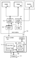
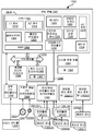
도 1은 하나 이상의 예시적인 구현예에 따라, 광 패턴을 투사 및 캡처하여, 공지된 투사 패턴 데이터와의 매칭을 통해 깊이를 결정하도록 구성될 수 있는 예시적인 컴포넌트를 나타내는 블록도이다.
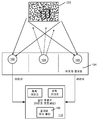
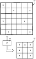
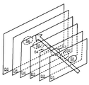
도 2와 도 3은 하나 이상의 예시적인 구현예에 따라, 장면에 도트를 투사하여 캡처된 이미지 데이터를 공지된 투사 패턴 이미지와 매칭시킴으로써 깊이를 결정하는 예를 나타내는 도면이다.
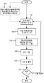
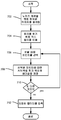
도 4는 하나 이상의 예시적인 구현예에 따라, 공지된 투사 패턴 데이터에 기초하여 깊이 맵을 결정할 때에 이용되는 예시적인 단계들을 나타내는 흐름도이다.
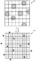
도 5는 하나 이상의 예시적인 구현예에 따라, 서브픽셀 해상도에서 도트 피크 위치를 결정하는데 투사 도트가 어떻게 이용될 수 있는지를 나타내는 도면이다.
도 6은 하나 이상의 예시적인 구현예에 따라, 도트 관련 데이터가 어떻게 데이터 구조로 압축될 수 있는지를 나타내는 도면이다.
도 7은 하나 이상의 예시적인 구현예에 따라, 도트 피크 위치를 결정하는데 이용될 수 있는 예시적인 단계들을 나타내는 흐름도이다.
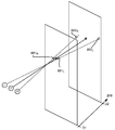
도 8은 하나 이상의 예시적인 구현예에 따라, 깊이 데이터를 결정하기 위해 예측 도트 위치를 공지된 투사 도트 패턴 위치와 매칭시킬 때에 투사선(projected ray)에서 기인한 도트가 어떻게 이용될 수 있는지를 나타내는 도면이다.
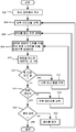
도 9는 하나 이상의 예시적인 구현예에 따라, 상이한 깊이에서의 매칭 (신뢰도) 스코어를 결정하기 위해 각각의 투사 도트에 대해 각각의 이미지 캡처된 도트를 평가하는데 이용될 수 있는 예시적인 단계들을 나타내는 흐름도이다.
도 10은 하나 이상의 예시적인 구현예에 따라, 매칭이라고 간주되기에 도트 피크가 충분히 가까운지의 여부를 결정하는데 이용될 수 있는 예시적인 단계들을 나타내는 흐름도이다.
도 11은 하나 이상의 예시적인 구현예에 따라, 깊이 산출이 준폐색 이미지(semi-occluded image)에 얼마나 강력할 수 있는지를 나타내는 도면이다.
도 12는 하나 이상의 예시적인 구현예에 따라, 보간이 어떻게 상이한 깊이에서의 신뢰도 스코어에 기초할 수 있는지를 나타내는 도면이다.
도 13은 여기에 설명하는 다양한 실시형태들의 하나 이상의 양태가 구현될 수 있는, 게이밍 시스템의 형태로, 예로 드는 비제한적인 컴퓨팅 시스템 또는 동작 환경을 나타내는 블록도이다. The present invention is illustrated by way of example and not limitation in the accompanying drawings in which like reference numerals refer to like elements.
1 is a block diagram illustrating an exemplary component that may be configured to project and capture a light pattern to determine depth through matching with known projection pattern data, in accordance with one or more exemplary embodiments.
Figures 2 and 3 are diagrams illustrating an example of determining depth by projecting dots in a scene and matching the captured image data with a known projection pattern image, in accordance with one or more illustrative embodiments.
4 is a flow diagram illustrating exemplary steps used in determining a depth map based on known projection pattern data, in accordance with one or more exemplary embodiments.
5 is a diagram illustrating how a projection dot can be used to determine a dot peak position at a subpixel resolution, in accordance with one or more exemplary embodiments.
Figure 6 is a diagram illustrating how dot related data can be compressed into a data structure, in accordance with one or more illustrative embodiments.
7 is a flow diagram illustrating exemplary steps that may be used to determine a dot peak position, in accordance with one or more exemplary embodiments.
8 is a diagram illustrating how a dot resulting from a projected ray can be used to match a predicted dot position to a known projected dot pattern position to determine depth data, in accordance with one or more exemplary embodiments. to be.
9 is a flow diagram illustrating exemplary steps that may be used to evaluate each image captured dot for each projection dot to determine a matching (confidence) score at different depths, in accordance with one or more exemplary embodiments. to be.
10 is a flow diagram illustrating exemplary steps that may be used to determine whether a dot peak is sufficiently close to be considered a match, in accordance with one or more exemplary embodiments.
11 is a diagram illustrating how powerful the depth calculation can be for a semi-occluded image, in accordance with one or more exemplary embodiments.
12 is a diagram illustrating how interpolation can be based on confidence scores at different depths, in accordance with one or more exemplary implementations.
Figure 13 is a block diagram illustrating an exemplary non-limiting computing system or operating environment in the form of a gaming system in which one or more aspects of the various embodiments described herein may be implemented.
여기에 설명하는 기술의 다양한 양태들은, 장면에 투사되는 공지된 광 패턴을 갖는 것과, (다른 기술에 비해) 대체로 보다 정확하고 믿을 수 있는 깊이 추정을 제공하기 위해 캡처된 이미지 및 공지된 패턴에 대해 이미지 프로세싱을 이용하는 것에 관한 것이다. 또한 이 기술은 픽셀보다는 도트에 대한 계산(enumerating), 3안렌즈(trinocular)(또는 3-웨이 이상의) 매칭, 서브픽셀 해상도의 이용, 및 신뢰도 기반의 보간 등의, 여기에 설명하는 하나 이상의 다양한 기술을 활용한다. 광 패턴은, 그 광 패턴이 계획된 패턴으로 또는 랜덤한(그러나 그 후에는 변하지 않는) 패턴으로 생성되는지의 여부에 관계 없이, 미리, 예컨대 제조 시에 캘리브레이션되거나 사용자가 행한 캘리브레이션 동작에서 학습되는 공지된 고정형 구조일 수 있다. Various aspects of the techniques described herein may be used with known light patterns projected onto a scene and with captured images and known patterns to provide a generally more accurate and reliable depth estimate (as compared to other techniques) To image processing. This technique may also be applied to one or more of the various described herein, such as enumerating for dots rather than pixels, trinocular (or three-way or more) matching, use of subpixel resolution, Technology. The light pattern can be determined in advance, for example, at the time of manufacture, or in a known manner, which is learned in a calibration operation performed by a user, irrespective of whether the light pattern is generated in a planned pattern or in a random (but unchanging) It may be a fixed structure.
일 양태에 있어서, 2개 이상의 카메라가 장면의 이미지를 캡처하는데 이용된다. 예를 들어, 좌우의 스테레오 카메라로, 공지된 광 패턴과 함께 2개의 캡처된 이미지가, 깊이를 나타내는 디스패리티를 결정하기 위해 3-웨이 매칭 기술과 함께 이용될 수 있다. 다시 말해, 공지된 패턴, 좌측 이미지 및 우측 이미지가, 각각의 투사/캡처된 도트의 디스패리티에 기초한 깊이를 추정하는데 이용될 수 있다. 장면을 시찰하는 다수의 카메라를 구비하는 것은, 깊이 추정의 불확실성을 극복하게 하고, 미스매칭을 감소시키는 것을 돕는다. 또한, 이 기술은, 적어도 하나의 카메라가 장면을 시찰하고 프로젝터에 대한 이 카메라의 위치가 알려져 있다면, 카메라의 고장(failure)에 강력하여 (통상 신뢰성은 떨어지겠지만) 계속해서 깊이를 추정한다. In an aspect, two or more cameras are used to capture an image of a scene. For example, with left and right stereo cameras, two captured images with known light patterns can be used with a three-way matching technique to determine the disparity that represents the depth. In other words, the known pattern, the left image and the right image can be used to estimate the depth based on the disparity of each projected / captured dot. Having multiple cameras to inspect the scene helps overcome the uncertainty of depth estimation and helps reduce mismatch. This technique also continues to estimate the depth, though at least one camera inspects the scene and the position of this camera relative to the projector is known, which is robust to camera failure (which usually would be unreliable).
보다 정확한 서브픽셀 디스패리티가 주어진다면, 서브픽셀 정확성에 따라 도트의 위치를 추정하는 것을 포함하는, 도트 검출 프로세스가 이용될 수 있다. 이것은 보다 정확한 매칭을 위한 것이며 디스패리티를 이산화하는 것을 피한다. Given a more accurate subpixel disparity, a dot detection process may be used, including estimating the position of the dot according to subpixel accuracy. This is for more accurate matching and avoids discretizing disparity.
산출된 매칭 스코어(예컨대, 픽셀마다 추정된 깊이의 신뢰도에 각각 대응)를, 픽셀에 대해 추정된 도트 기반의 깊이를 갖지 않고 픽셀에 대해 깊이를 산출하는데 이용하는 보간이 이용될 수 있다. 예를 들어, 각각의 깊이에서의 신뢰도는 보간 연산에서 가중치로서 이용될 수 있다. 이것은, 컬러(예컨대, RGB) 이미지 및 깨끗한(clean) IR 이미지에 기초한 에지 기반의 데이터 등의, 가능하다면 다른 데이터와 함께, 보간을 위한 가이드로서 역할한다. Interpolation may be used that uses the calculated matching score (e.g., corresponding to the reliability of the estimated depth for each pixel) to calculate the depth for the pixel without having an estimated dot-based depth for the pixel. For example, reliability at each depth can be used as a weight in an interpolation operation. It serves as a guide for interpolation, possibly with other data, such as edge-based data based on color (e.g., RGB) images and clean IR images.
여기에서의 예들은 전부 비제한적인 것임을 이해해야 한다. 예를 들어, 여기에서 일반적으로 예시하는 투사 광 패턴은 대체로 원형의 도트를 포함하지만, 투사 도트는 임의의 형상에 속할 수도 있다(도트 등의 2차원의 투사 형상이 스트라이프 등의 1차원의 투사보다 더 정확한 매칭을 돕는 경향이 있기는 하다). 이처럼, 본 발명은 어떤 특정 실시형태, 양태, 개념, 구조, 기능 또는 여기에서 설명하는 예에 제한되지 않는다. 그보다는, 여기에서 설명하는 특정 실시형태, 양태, 개념, 구조, 기능 또는 여기에서 설명하는 예들은 전부 비제한적이며, 본 발명은 일반적으로 깊이 감지 및 이미지 프로세싱에서 다양하게 이용되어 장점 및 효과를 제공할 수 있다. It should be understood that the examples herein are all non-limiting. For example, although the projection light pattern generally exemplified herein includes generally circular dots, the projection dots may belong to any shape (a two-dimensional projection shape such as a dot is more preferable than a one-dimensional projection such as a stripe) There is a tendency to help more accurate matching). As such, the present invention is not limited to any particular embodiment, mode, concept, structure, function, or example described herein. Rather, the specific embodiments, aspects, concepts, structures, functions, or examples described herein are by no means intended to be limiting, and the present invention is generally employed in depth sensing and image processing to provide advantages and effects can do.
도 1은 이미지 캡처링 시스템의 스테레오 카메라(102, 103)가 시간 동기화된(예컨대, 카메라가 "젠록 상태(genlocked)"임) 좌측 및 우측 스테레오 이미지(105)를 캡처하는 예시적인 시스템을 보여준다. 일 구현예에서는, 카메라(102, 103)가 적외선(IR) 이미지를 캡처하는데, IR은 장면의 시각적 외관에 영향을 미치지 않기 때문이다(이러한 면은 화상 회의 및 오브젝트 모델링 애플리케이션 등에서 대체로 유리하다). 쉽게 이해하겠지만, 스튜디오 환경 등의 일부 시나리오에서는, 2개보다 많은 수의 IR 깊이 감지 카메라가 존재할 수도 있다. 또한, 소정의 시스템에서는 RGB 카메라 등의 하나 이상의 다른 카메라도 존재할 수 있는데, 이러한 다른 카메라는 예컨대 깊이 추정을 돕는데 이용될 수 있다. Figure 1 shows an exemplary system for capturing left and
도 1에서는, 장면에 도트의 패턴 등의 IR 패턴을 투사하는 프로젝터(106)를 나타내고 있지만, 다른 스팟 형상 및/또는 패턴 타입이 이용될 수도 있다. 간결함을 위해, 이하에서는 주로 도트를 설명한다. 패턴은 레이저 광을 장면에, 예컨대 도트 패턴으로서 분산시키는 회절성 광학 컴포넌트(회절성 광학 엘리먼트 또는 엘리먼트들의 조합)으로 설계(예컨대, 인코딩)될 수 있다. 전술한 바와 같이, 패턴은 계획적일 수도 또는 랜덤일 수 있으나, 캘리브레이션에 의해 학습된다. 1 shows a
도 2와 도 3은 투사 개념을 예를 들어 설명하고 있다. 도 2에서는 스테레오 카메라(102, 103) 사이의 원으로서 표시되고, 도 3에서는 디바이스(334)에 통합된 회절성 광학 엘리먼트(332)에 결합된 레이저(330)로서 표현되는 프로젝터(106)는 도트 패턴을 장면(222; 도 2)에 투사한다. 캘리브레이션을 거쳐, 투사 도트 패턴(108)이 깊이 추정기(depth estimator)(110)에 공지되는데, 이 추정기는 이미지 프로세싱 시스템 또는 서브시스템(112)의 부분일 수 있다. 공지된 도트 패턴은 임의의 적합한 데이터 구조로 유지될 수 있고, 일 구현예에서는, 여러 개의 가능한 깊이에서의 각 도트의, (후술하는 바와 같은 서브픽셀 해상도에 있을 수 있는), 적어도 (x, y) 좌표를 추적하는데, 이것은 각 도트의 투사선(projected ray)을 저장하는 것에 대응한다. 대안은 각각의 도트를 비트 벡터로서 표시하는 것인데, 비트 벡터는 벡터로 마찬가지로 표시되는, 카메라 캡처된 도트와 벡터 매칭하는 인접부(neighbor)를 포함한다. FIGS. 2 and 3 illustrate the projection concept by way of example. The
카메라(102, 103)는 장면(222)과 (가능하다면) 배경 내의 오브젝트 표면에서 반사될 때의 도트를 캡처한다. 일반적으로, 캡처된 도트의 하나 이상의 특징은 반사 표면까지의 거리는 나타낸다. 도 2와 도 3(또는 본 명세서 내의 도면들 중 어느 것)은 실측으로 도시된 것도 아니며, 서로 동일한 장면을 표시하지도 않고, 어떤 사이즈, 거리, 도트 분포 패턴, 도트 밀도 등을 시사하지도 않는 것이 의도된다. The
프로젝터(106)의 배치는 카메라 외부에(예컨대, 도 1), 또는 카메라들 사이에(예컨대, 도 2와 도 3), 또는 카메라의 한쪽 또는 양쪽 위 또는 아래 등의 다른 위치에 있을 수 있음을 알아야 한다. 여기의 예들은 카메라 및/또는 프로젝터가 서로에 대해 어디에 위치하는지에 대해 절대 제한하지 않으며, 마찬가지로, 카메라들은 서로에 대해 상이한 위치에 배치할 수도 있다. 그러나, 카메라와 프로젝터의 상대 위치는, 예컨대 제조 시에 결정되고/되거나 필요하다면 재측정 가능한 것으로 공지된다. It is noted that the arrangement of the
장면을 비교적 다수의 분산형 적외선 도트, 예컨대 통상 대략 수백 또는 수천개로 조사(illuminating)하여, 카메라(102, 103)는 장면 내의 임의의 오브젝트에 대한 적외선 이미지 데이터의 일부로서 텍스처 데이터를 캡처한다. 여기에 설명하겠지만, 좌측 및 우측 이미지 사이의 보다 정확한 도트 매칭을 돕기 위해, 공지된 도트 패턴과 함께, 이미지 내의 도트가 프로세싱된다. The scene is illuminated with a relatively large number of scattered infrared dots, e.g., typically in the hundreds or thousands, so that the
일 구현예에 있어서, 예시적인 이미지 캡처링 시스템 또는 서브시스템(104)은 카메라 인터페이스(116)를 통해 카메라(102, 103)의 동작을 제어하는 컨트롤러(114)를 포함한다. 예시하는 컨트롤러(114)는 프로젝터 인터페이스(118)를 통해 프로젝터(106)의 동작도 제어할 수 있다. 예컨대, 카메라(102, 103)는 컨트롤러 신호(또는 각 카메라마다 상이한 신호) 등에 의해, 동시에 스테레오 이미지를 캡처하도록 동기화된다(젠록된다). 프로젝터(106)는 턴온형 또는 턴오프형, 펄스형일 수도 있고, 다르게는 예컨대 제어 가능하게 변하는 하나 이상의 파라미터를 가질 수도 있다. In one embodiment, an exemplary image capturing system or
카메라(102, 103)에 의해 캡처된 이미지(105)는 이미지 프로세싱 시스템 또는 서브시스템(112)에 제공된다. 일부 구현예에 있어서, 이미지 프로세싱 시스템(112)과 이미지 캡처링 시스템 또는 서브시스템(104), 또는 이들의 부분은 단일 디바이스로 조합될 수도 있다. 예를 들어, 홈 엔터테인먼트 디바이스가 도 1에 도시한 컴포넌트(그 외에도 도시하지는 다른 것들)를 모두 포함할 수도 있다. 다른 구현예에서는, 카메라와 프로젝트 등의, 이미지 캡처링 시스템 또는 서브시스템(104)의 부분(또는 전부)이, 게이밍 콘솔, 개인용 컴포터, 모바일 디바이스, 전용 프로세싱 디바이스 및/또는 기타 동류에 연결되는 별도의 디바이스 내에 있을 수도 있다. 실제로, 이하에서는 이미지를 깊이 데이터에 프로세싱하는데 이용될 수 있는 한 환경으로서 게이임 콘솔을 예로 든다. An
이미지 프로세싱 시스템 또는 서브시스템(112)은 프로세서(120)와, 깊이 추정기(110) 등의 하나 이상의 이미지 프로세싱 컴포넌트를 포함하는 메모리(122)를 포함한다. 일 양태에 있어서, 깊이 추정기(110)는 깊이 데이터를 추정하기 위해 이미지뿐만 아니라 공지된 프로젝터 패턴(106)을 이용하는 3안렌즈 매칭 컴포넌트(trinocular matching component)(126) 등을 포함한다. 하나 이상의 깊이 맵(128)은 여기에 설명하는 바와 같이 깊이 추정기(110)를 통해 취득될 수 있다. The image processing system or
또한, 도 1에는, 예컨대 컴퓨터 프로그램, 키보드, 게임 컨트롤러, 디스플레이, 포인팅 디바이스, 음석 인식용 마이크, 및/또는 사용자가 애플리케이션과, 또는 깊이 맵을 이용하는 기타 등등과 상호작용하기에 적절한 동류의 디바이스를 접속시키기 위한, 이미지 프로세싱 시스템 또는 서브시스템(118)에의 인터페이스(132)도 도시되어 있다. 1 also illustrates a similar device suitable for interacting with an application, or with a depth map, etc., for example, a computer program, a keyboard, a game controller, a display, a pointing device, a speech recognition microphone, An
도 4는 단계 400에서, 이를테면 디바이스의 제조 시에 한번의 캘리브레이션 프로세스를 포함하는, 하나의 전체 프로세스의 예시적인 단계들을 보여주는 일반화된 흐름도이다. (캘리브레이션은 디바이스 소유자에 의해, 또는 시핑(shipping), 가열, 또는 기타 환경적 요인으로 드리프트가 발생하는 경우처럼 서비스를 위해 디바이스를 보냄으로써 반복될 수도 있다.) FIG. 4 is a generalized flow diagram illustrating exemplary steps of an overall process, including a single calibration process at
깊이 맵 작성에 이용되는 예시적인 단계들은 이하에서 더 자세히 설명되며, 일반적으로, 단계 402에서 나타내는 바와 같이(그리고 도 7을 참조해서) 카메라에 의해 캡처된 도트의 위치를 찾아서 저장하는 도트 검출 프로세스를 포함한다. 카메라에 의해 캡처된 도트를 나타내는 데이터는, 일반적으로 단계 404에서 나타내는 바와 같이(그리고 도 9와 도 10을 참조해서), 공지된 투사 도트를 나타내는 데이터에 대해 매칭된다. Exemplary steps used in depth map generation are described in more detail below and generally include a dot detection process for locating and storing the position of the dots captured by the camera as shown in step 402 (and with reference to FIG. 7) . The data representing the dots captured by the camera are generally matched against the data representing the known projection dots, as shown in step 404 (and with reference to Figures 9 and 10).
매칭 후에는, 일반적으로 이상치(anomaly)를 없애는 일부 포스트프로세싱(post-processing)이 단계 406에서 행해질 수 있다. 단계 408에서는 직접적인 도트 기반의 추정 깊이 값을 갖지 않는 픽셀에 대해, 예컨대 도트 사이에 있는 픽셀에 대해 깊이 값을 결정하기 위해 보간이 행해진다. 보간은, 직접적인 도트 기반의 추정 깊이 값을 갖는 인접한 픽셀의 신뢰도 스코어뿐만 아니라, 깊이가 픽셀마다 변할 가능성이 있는지의 여부―픽셀이 전경 오브젝트의 에지 넘을 수도 있기 때문에―를 계산에 넣는 에지 검출 등의 다른 기술에도 기초할 수 있다. After matching, some post-processing may generally be performed at
깊이 맵을 완성하는데 필요한 픽셀 깊이 값을 보간으로 채운 후에, 단계 410에서 깊이 맵을 출력한다. 이 프로세스는, 깊이 맵의 프레임이 더 이상 필요하지 않을 때까지, 예컨대 디바이스가 턴 오프될 때까지, 깊이 맵의 프레임을 원하는 애플리케이션이 닫히거나 모드를 변경하거나 등등의 경우에 이를 때까지, 단계 412를 거쳐 적절한 프레임 레이트로 반복된다. After filling the pixel depth values required to complete the depth map with interpolation, the depth map is output in
도트 검출과 관련하여, 일반적으로, 도트는 가우시안 원이나 블러링된 원(blurred circle)과 같은 소프트한 순환 대칭 프로파일을 갖는다(정확한 형상은 실질적으로 중요하지 않다). 적외선 이미지에 있어서, 도트의 적어도 일부에 의해 조사되는 각 픽셀은 연관된 강도 값을 갖는다. 하나 이상의 구현예에 있어서, 각각의 입력 이미지는 블러링되는데, 예컨대 (이미지 프로세싱에서 공지되어 있는 바와 같이) 각 픽셀마다 1-2-1 필터가 사용되어 노이즈를 저감시킨다. 다음의 동작은, s x s 면적 내에서 각각의 픽셀을 비교하여 로컬 최대치인(또는 최대치에 필적하는) 픽셀을 찾기 위해 이미지에 대해 s x s 맥스 필터(max filter)(각 윈도우 위치에서 최대 강도 값을 찾는 슬라이딩 s x s 윈도우로서, 이 역시 이미지 프로세싱 분야에서 잘 알려져 있음)를 이용한다. s에 대한 적절한 값은 5이다. With respect to dot detection, dots generally have a soft circular symmetry profile, such as a Gaussian circle or a blurred circle (the exact shape is not really important). In an infrared image, each pixel illuminated by at least a portion of the dot has an associated intensity value. In one or more embodiments, each input image is blurred, e.g., a 1-2-1 filter is used for each pixel (as is known in image processing) to reduce noise. The next operation is to compare each pixel within the sxs area to determine the maximum value of the sxs max filter for the image (to find the maximum intensity value at each window position) sxs window, also well known in the field of image processing). The appropriate value for s is 5.
이러한 로컬 최대 포인트마다, 그 강도에 대한 수평 및 수직의 3포인트 포물선 피트(parabolic fit)가 서브픽셀 피크 위치와 그 위치에서의 최대 (예컨대, 보간된) 값을 찾는데 이용된다(즉, 보간은 피크가 서브픽셀에서 중심에 있지 않을 경우에 대해 조정하는데 이용될 수 있다. 픽셀(도 5의 부분적 이미지(550)의 정사각형으로 표시)에서 볼 수 있는 바와 같이, 이 도트 패턴에 대한 특징이 도트 피크 강도 위치이다. 이것은 서브픽셀 정확도 내에서 추정될 수 있다. 보다 구체적으로, 도 5에 나타내는 바와 같이, 더 미세한 그리드 그림(550)에 있는 X자형 크로스는 추정된 도트 중심을 나타내며, 픽셀은 점선에 의해 서브픽셀로 나누어져 있다. 각각의 추정된 중심이 서브픽셀에 대응한다. 예로 든 그리드 바깥에 있는 일부 추가 도트의 중심도 표시되어 있다(예컨대, 그리드가 더 큰 이미지의 일부일 수 있다). For each such local maximum point, a horizontal and vertical three-point parabolic fit to its intensity is used to find the subpixel peak position and the maximum (e.g., interpolated) value at that location (i.e., (As indicated by the square of the
도 5는 해상도를 2배로 하기 위해 픽셀을 2 x 2 서브픽셀로 세분한 것임을 알아야 한다. 그러나, 더블 서브픽셀 해상도 대신에, 픽셀을 더 세분하여, 예컨대 각각 9개의 서브픽셀, 각각 16개의 서브픽셀 등으로 하여 훨씬 더 높은 해상도를 얻을 수도 있다(비(non)정사각 세분을 이용할 수도 있다). It should be noted that Fig. 5 is a subdivision of a pixel into 2 x 2 subpixels in order to double the resolution. However, instead of the double subpixel resolution, the pixel may be further subdivided to obtain a much higher resolution (using a non square subdivision, for example, with 9 subpixels each, 16 subpixels each, etc.) .
검출된 피크를 나타내는 데이터는, 각 피크마다 서브픽셀 위치와 피크 크기를 포함하고, 도트 매칭 시에, 매칭 스코어 등의 정보를 축적하는 추가 공간도 제공하는 데이터 구조로 저장될 수 있다. 하나 이상의 구현예에 있어서, 회절성 광학 엘리먼트의 구축으로, 피크는 d픽셀 이상 떨어져 있지 않고 그래서 더 작은 데이터 구조(셀 어레이를 포함하는 스토리지 이미지)가 이용될 수도 있다. 보다 구체적으로, 도 6에 도시하는 바와 같이, 압축 동작(660)에서는, 이미지(662)로부터 취득된 각 피크에 대한 데이터가, 이미지의 실제 위치를 d로 나누어서 최근접 픽셀로 라운딩하여 산출된 빈(bin)에 입력되어, 압축된 이미지 구조(664)를 제공한다. 도 6의 셀의 그리드는 도 5에서와 같은 서브픽셀 그리드를 나타내는 것이 아니라, 그보다는, 피크를 갖지 않는 다수의 픽셀에 대한 스토리지를 유지할 필요성을 없앰으로써, 데이터 구조의 요구 사이즈를 압축할 수 있는 방법을 나타내는 것임을 알아야 한다. Data representing the detected peaks may be stored in a data structure that includes subpixel positions and peak sizes for each peak and also provides additional space for accumulating information such as matching scores at dot matching. In one or more embodiments, with the construction of the diffractive optical element, the peaks are not separated by more than d pixels and so a smaller data structure (storage image including cell array) may be used. More specifically, as shown in Fig. 6, in the
적합한 압축 파라미터는, 도트(피크) 사이의 공간을 가능한 한 많이 제거하기에 충분히 크지만, 2개의 다른 도트가 소형 셀에서 충돌하지 않을만큼 충분히 작은 것이다. 전술한 예에서는, 임의의 쌍의 피크들이 서로로부터 적어도 2픽셀만큼 떨어져 있기 때문에, 압축 인수 2가 사용되었다. Suitable compression parameters are sufficiently large to remove as much space as possible between dots (peaks), but small enough that two different dots do not collide in a small cell. In the example described above,
도 7은 예시적인 도트 검출 프로세스를 정리한 것이며, 이 프로세스는 노이즈를 줄이기 위해 캡처된 이미지를 블러링하는 단계 703에서 시작된다. 도 7은 각 이미지, 예컨대 좌측 이미지와 우측 이미지에 대해 수행되며, 적어도 어느 정도까지는 동시에 수행될 수 있음을 알아야 한다. 단계 704는 피크를 찾기 위해 맥스 필터를 이용하는 것을 나타낸다. FIG. 7 is a summary of an exemplary dot detection process, which begins with step 703 of blurring the captured image to reduce noise. It should be noted that FIG. 7 is performed for each image, e.g., the left image and the right image, and may be performed at least to some extent simultaneously. Step 704 shows the use of a max filter to find a peak.
각 피크마다, 또는 로컬 최대 포인트에 대해, 단계 706, 708, 및 710에서는 피크의 서브픽셀 위치와, 그 위치에서의 (예컨대, 보간된) 강도 값을 포함하는, 대표 정보를 데이터 구조로 저장한다. 이것은, 도 6에 나타내는 바와 같이, 회절성 광학 엘리먼트의 설계 때문에, 통상 성긴 데이터 구조를 채운다. 단계 712에서는 데이터 구조를 압축하는데, 이에 대해서는 도 6을 참조해서 도시 및 설명한다. For each peak, or local maximum point, in
도트 피크를 찾고 이들을 압축된 데이터 구조로 저장하기 위해 이미지를 프로세싱하였으면, 매칭이 일어난다. 일 대안으로는 3안렌즈 도트 매칭이 이용된다. 각 픽셀을 프로세싱하는 것 대신에, 일 구현예에서는, 3안렌즈 매칭이 플레인 스위프 알고리즘(plane sweep algorithm)을 이용하여 레이저 도트 패턴 내의 각 도트에 대한 디스패리티를 추정한다. 프로젝터 패턴이 공지(캘리브레이션 동작 시에 산출되어 저장)되어 있기 때문에, 3안렌즈 도트 매칭은 도트마다 디스패리티를 추정하기 위해 공지된 패턴 내의 각 도트를 좌측 및 우측 이미지 양쪽과 매칭시킨다. Once the images have been processed to find dot peaks and store them in a compressed data structure, matching occurs. One alternative is to use 3-lens lens dot matching. Instead of processing each pixel, in one implementation, the three-lens lens matching estimates the disparity for each dot in the laser dot pattern using a plane sweep algorithm. Since the projector pattern is known (calculated and stored at the time of the calibration operation), the three-lens-lens dot matching matches each dot in the known pattern with both the left and right images in order to estimate the disparity per dot.
일반적으로, 공지된 패턴의 경우, 상이한 깊이에서의 도트의 광선 (x, y) 위치는 미리 산출될 수도 있다. 도 8에 도시하는 바와 같이, 깊이가 D1에 있다면, 좌측 카메라 이미지는 (서브픽셀) 881L에서 대응하는 도트를 가져야 하고, 우측 카메라 이미지는 (서브픽셀) 881R에서 대응하는 도트를 가져야 하며, 깊이가 D2에 있다면, 이들 서브픽셀 위치는 각각 882L 및 882R로 시프트될 것이다. 각각의 가능한 깊이가 이용될 수도 있지만, 하나 이상의 구현예에서는, 깊이의 일부의 샘플링이 이용될 수도 있다. 예를 들면, 하나의 픽셀에 대해 변하는 깊이 변화가 이용될 수 있는데, 깊이 변화는 그 역깊이(inverse depth)에 관련될 수 있다. In general, for known patterns, the ray (x, y) positions of the dots at different depths may be calculated in advance. 8, the left camera image should have a corresponding dot in (subpixel) 881L, the right camera image should have a corresponding dot in (subpixel) 881R, and the depth D2, these subpixel positions will be shifted to 882L and 882R, respectively. Although each possible depth may be used, in one or more embodiments, sampling of a portion of the depth may be used. For example, a depth variation that varies for one pixel can be used, wherein the depth variation can be related to its inverse depth.
공지된 패턴에서 소정의 깊이 및 도트 위치에 대해, 각각의 이미지는, 그 깊이에서 예측되는 대응 위치에 도트를 갖고 있는지의 여부를 결정하는 것을 포함해, 각각의 이미지가 디스패리티 스위프(disparity sweep)로 프로세싱된다. 연산 효율성을 위해, 3-웨이 매칭이 타일 단위(tile-by-tile basis)로 동작할 수 있으며(그리고 타일은 2D 지원이 적절하게 집성될 수 있도록 늘려질 수도 있으며), 이 경우 각각의 타일은 그 자신의 디스패리티 스위프가 행해진다. For a given depth and dot position in a known pattern, each image includes determining whether it has a dot at a corresponding location predicted at that depth, such that each image has a disparity sweep, Lt; / RTI > For computational efficiency, 3-way matching can operate on a tile-by-tile basis (and tiles may be stretched so that 2D support can be properly aggregated), in which case each tile Its own disparity sweep is performed.
일 구현예에 있어서, 디스패리티 스위프는 대역이 MatchTriplet structure에 대응하는 다중 대역 이미지(multi-band image)에서 매칭 달성 스코어(winning match score)를 반환한다.In one implementation, the disparity sweep returns a winning match score in a multi-band image where the band corresponds to a MatchTriplet structure.
struct MatchPair struct MatchPair
{ {
float score; // matching score (# similar neighbors) float score; // matching score (# similar neighbors)
float d; // estimated disparity float d; // estimated disparity
};};
struct MatchStack struct MatchStack
{ {
MatchPair curr; // newest match being considered MatchPair curr; // newest match being considered
MatchPair prev; // previous match MatchPair prev; // previous match
MatchPair best; // best match so far MatchPair best; // best match so far
};};
struct MatchTriplet struct MatchTriplet
{ {
MatchStack left; // match in left image MatchStack left; // match in left image
MatchStack right; // match in right image MatchStack right; // match in right image
MatchPair both; // match in both images MatchPair both; // match in both images
};};
도 9에 도시하는 바와 같이, 디스패리티 스위프는, 측정되어야 하는 최소 및 최대 깊이를 나타내는 디스패리티 스위프 범위 (dMin, dMax)가 지정된 모든 디스패리티에 대해 외측 반복(단계 902, 920 및 922)을 가진다. 디스패리티 스위프는 우측 및 좌측 이미지에 대한 중간 반복(단계 902, 920 및 922)과, 타일 내의 (x, y) 피크 셀에 대한 내측 반복(단계 906, 912 및 914)을 포함한다. 9, the disparity sweep has outer repetitions (
일반적으로, 현재 깊이에 대해, 단계 908에서의 내측 루프는 투사 도트의 위치와 예측된 좌측 도트 위치에서 매칭이 있는지의 여부와, 마찬가지로 투사 도트의 위치와 예측된 우측 도트 위치에서 매칭이 있는지의 여부를 평가한다. 그러나, 대개 노이즈 때문에, 매칭이 있어야 하더라도, 정확한 위치에 있지 않을 수도 있고, 그렇기 때문에, 일 구현예에서는 인접부/인접한 픽셀 또는 서브픽셀도 평가된다. In general, for the current depth, the inner loop at
일반적으로, 유사한 인접부가 많을수록 매칭이 있다는 신뢰도도 높아진다. 인접부와 관련하여, 공간적으로 지원을 집성하기 위해, 양립 가능한 디스패리티를 가진 인접부의 스코어는, 예컨대 UpdateNeighbors 루틴을 호출함으로써 상승한다. 이 동작은, (각각의 피크의 인접한 거리 내에 있는) 인접부의 수가, 매칭 달성 결정이 기반으로 할 수 있는 스코어이기 때문에, 가능한 매칭들 사이를 명확하게 한다. In general, the greater the likelihood of matching, the greater the likelihood of matching. With respect to the adjacencies, in order to aggregate support spatially, the score of the adjacency with compatible disparities is raised, for example, by calling the UpdateNeighbors routine. This operation clarifies the possible matches because the number of adjacencies (within the adjacent distance of each peak) is a score that a match-making determination can be based on.
도트를 패턴 데이터와 매칭시키는 대안적 방법(또는 추가 방법)은 각각의 캡처된 도트를 벡터로, 그리고 각각의 공지된 투사 도트를 벡터로 표시하는 것인데, 이들 벡터는 도트의 주변 인접부(픽셀 또는 서브픽셀 값)에 대한 데이터를 포함한다. 도트의 공지된 투사 패턴에 대한 벡터 표시는 미리 산출되어 룩업 테이블 등에 유지될 수도 있다. 예컨대 캡처된 도트 벡터를 상이한 깊이에서의 벡터 세트에 대해 평가하는 최근접 벡터에 최고 신뢰도 스코어가 주어지고, 다음의 최근접 벡터에는 다음의 최고 신뢰도 스코어가 주어지며, 등등으로, 최저 신뢰도 스코어까지 이어진다. An alternative method (or an additional method) for matching dots with pattern data is to display each captured dot as a vector and each known projection dot as a vector, which are adjacent to the periphery of the dot Subpixel value). A vector representation of a known projection pattern of dots may be calculated in advance and held in a look-up table or the like. For example, the closest vector that evaluates the captured dot vector for a set of vectors at different depths is given the highest confidence score, the next closest vector is given the next highest confidence score, and so on, to the lowest confidence score .
벡터는 비트 벡터일 수 있는데, 각각의 비트 값은 인접부의 각각의 주변 위치에 대해 도트의 존재 여부를 나타낸다. 그런 다음, 캡처된 이미지 내의 각각의 도트에 대해, 그 도트의 인접부의 비트 벡터를 산출한 후에, 비트 벡터들 간의 거리(예컨대, 해밍 거리)를 최근접 매칭을 찾는데 이용할 수 있다. 이것은 예컨대 저가의 하드웨어로 효율적으로 행해질 수도 있는 것을 알아야 한다. 또한, 이 벡터 기반의 기술은 소정의 애플리케이션, 예컨대 골격 추적(skeletal tracking)에 매우 적합할 수 있다. The vector may be a bit vector, where each bit value indicates the presence or absence of a dot for each surrounding location in the neighborhood. Then, for each dot in the captured image, after calculating the bit vector of the neighborhood of the dot, the distance between the bit vectors (e.g., the hamming distance) may be used to find the closest match. It should be noted that this may be done efficiently, for example, with inexpensive hardware. In addition, this vector-based technique may be well suited for certain applications, such as skeletal tracking.
하나 이상의 구현예에 있어서, 디스패리티 스위프 스테이지 내의 최심 레벨에는 2개의 피크가 양립 가능한지의 여부를 테스트하는 TestMatch 서브루틴(예컨대, 도 10)이 있다. 피크들은 등극선 기하구조(epipolar geometry)에서 충분히 가깝다면 양립 가능하다(이용될 수 있는 다른 테스트는 좌측 및 우측 피크가 동일한 크기를 갖는지의 여부를 체크하는 것임을 알아야 한다). 스코어(등극선 거리)가 허용한계(tol) 파라미터 내에 있고(단계 1002), 새로운 매칭이면(단계 1004), 이 매칭을 MatchStack 구조에 푸시하기 위해 NewMatch 루틴이 이용될 수 있다(단계 1006). tol 파라미터에 대한 적합한 값은 1.5 픽셀로 설정될 수 있다. In one or more embodiments, there is a TestMatch subroutine (e.g., FIG. 10) that tests whether the two peaks are compatible at the lowest level in the disparity sweep stage. Peaks are compatible if they are close enough to the epipolar geometry (note that other tests that can be used are to check whether the left and right peaks have the same size). If the score is in the tol parameter (step 1002), then a new match (step 1004), a NewMatch routine may be used to push the match to the MatchStack structure (step 1006). The appropriate value for the tol parameter can be set to 1.5 pixels.
매칭 스테이지의 말미에서, 각 프로젝터 피크에 대한 MatchStack 구조는 그것의 최상 필드(best field)에서 매칭 달성(winning match)을 포함한다. MatchTriplet는 좌측 이미지에서의 최상 매칭(best match), 우측 이미지에서의 최상 매칭, 및 좌측 및 우측 양측이 서로 일치하는 최상 매칭에 대해 매칭 달성을 갖는다. At the end of the matching stage, the MatchStack structure for each projector peak includes a winning match in its best field. MatchTriplet has a matching match for the best match in the left image, the best match in the right image, and the best match both left and right sides match.
실제 실행 시에는 좌측 및 우측 카메라에 의해 캡처되는 이미지에 작은 차이가 존재하고, 이에 일부 시나리오에서는 인접한 피크들이 검출 시에 하나의 도트로 병합된다. 이상적인 시나리오에 있어서, 좌측 이미지에 대한 최상 매칭, 우측 이미지에 대한 최상 매칭, 및 좌측 및 우측 양측에 대한 최상 매칭은 동일한 디스패리티가 될 것이며, 최상의 결합 디스패리티(best joint disparity)는 이상적으로 최상의 3-웨이 매칭된 디스패리티이다. 그러나, 노이즈, 임계치 미만의 강도 값 등이 도트 누락을 일으켜 상이한 디스패티리를 초래할 수 있다. There is a small difference in the image captured by the left and right cameras in actual practice, and in some scenarios, adjacent peaks are merged into one dot upon detection. In an ideal scenario, the best match for the left image, the best match for the right image, and the best match for the left and right sides will be the same disparity, and the best joint disparity will ideally be the best 3 - Way-matched disparity. However, noise, intensity values less than the threshold value, etc. may cause dot missing and result in different disparities.
또한, 준폐색(semi-occlusion)도 양 카메라가 동일한 도트를 보는 것을 막을 수 있다. 준폐색은 도 11에서 일반적으로 설명되는데, 도 11에서, 좌측 카메라(C1)는 그것의 대응하는 이미지(I1)에서 투사 도트(1100)를 캡처할 수 없지만, 우측 카메라(C2)는 그것의 이미지(I2)에서 할 수 있다. 이에, 유효한(그러나 스코어가 낮은) 3-웨이 매칭이 존재하더라도 도트의 깊이를 결정하기 위해 2뷰(2-view) 매칭이 최종 위너(final winner)가 되게 하는 강력한 결정(robust decision)이 이용될 수 있다. Also, semi-occlusion can prevent both cameras from seeing the same dot. 11, the left camera C1 can not capture the
최종 결과는 통상 신뢰도가 부정확한 도트 매칭으로 인해 스파스 에러(sparse error)를 갖는다. 이들 아티팩트는 하나 이상의 포스트프로세싱 단계를 수행함으로써 저감될 수 있다. 예를 들어, 한 단계는 실질적으로 5 x 5 인접부 내의 최근접 도트와는 실질적으로 상이한 디스패리티를 갖는 단일 이상 도트(single outlier dot)를 포함하는 플로팅 도트를 제거할 수 있다. 인접부 내의 도트의 디스패리티의 평균 및 표준 편차(시그마)는 이러한 용도로, 예컨대 3시그마를 초과해서평균 디스패리티와 상이하면 현재 픽셀에 할당된 디스패티리를 삭제하기 위해 이용될 수 있다. The end result usually has a sparse error due to incorrect dot matching. These artifacts can be reduced by performing one or more post processing steps. For example, one step may remove a floating dot comprising a single outlier dot having a disparity that is substantially different from the closest dot in the substantially 5 x 5 adjacencies. The average and standard deviation (sigma) of the disparities of the dots in the neighborhood can be used for this purpose, for example, to delete a disparity assigned to the current pixel if it differs from the average disparity in excess of three sigma.
다른 포스트프로세싱 단계는 유일성 체크(uniqueness check)를 수행하는 것이다. 이것은 좌측 및 우측 깊이 데이터에 관해, 특정 픽셀에 대해 상충하는 깊이가 없는 것을 체크한다. 일 구현예는 (투사, 좌측 픽셀) 쌍과 (투사, 우측 픽셀) 쌍을 고려하는데, 그 쌍들 중 어느 것에서 충돌(clash)이 있을 경우에, 스코어가 더 낮은 픽셀은 무효로 마킹된다. 대안적인 3-웨이 유일성 체크가 2-웨이 체크를 대신해 또는 추가로 이용될 수도 있다. Another post processing step is to perform a uniqueness check. This checks that for left and right depth data there is no conflicting depth for a particular pixel. One implementation considers a pair of (projection, left pixel) and (projection, right pixel) pair, where there is a clash at either of the pairs, the pixel with the lower score is marked invalid. An alternative 3-way uniqueness check may be used instead of or in addition to the 2-way check.
도트 매칭은 도트에 대해 디스패리티 기반의 깊이 추정치를 취득하게 하여, 성긴 디스패리티 맵이 되게 한다. 다음의 스테이지는, 예컨대 깊이 맵에, 매 픽셀에 대한 깊이 값을 제공하기 위해, 도트에서 추정된 저밀도 깊이(sparse depth)에서 시작하고 나머지 픽셀에서 누락 데이터를 보간하는 보간 동작(업샘플링(up-sampling) 스테이지)이다. 한 보간 프로세스는 장면의 고밀도 깊이(dense depth)를 복구하기 위해 매칭 스코어에 의해 그리고/또는 가이드 이미지 또는 이미지들(예컨대, 도트가 없는 깨끗한 IR 이미지 및/또는 RGB 이미지 또는 이미지들)에 의해 안내되는 푸시-풀(push-pull) 보간 기술을 이용한다. (깊이가 보간되고 있는) 픽셀과 사용중인 각각의 도트와의 거리는 보간이 가중되는 한 방법이다. Dot matching causes a disparity-based depth estimate to be obtained for the dot, resulting in a coarse disparity map. The next stage may be an interpolation operation (up-sampling) in which, for example, the depth map starts at a sparse depth estimated at the dot and interpolates missing data at the remaining pixels to provide a depth value for each pixel, sampling stage). An interpolation process may be performed by a matching score and / or guided by a guide image or images (e.g., a clean IR image and / or an RGB image or images without dots) to recover the dense depth of the scene Use a push-pull interpolation technique. The distance between the pixel (where the depth is interpolated) and each dot in use is the one as long as the interpolation is weighted.
도 12는 검출된 도트와 연관된 신뢰도 스코어(예컨대, S1-S6)의 개념을 나타내고 있다. 예를 들어, 도 12에서 화살표로 나타내는 소정의 광선에 대해, 카메라가 인접한 도트를 검출할 수도 있지만, 스코어(S3)로 나타내는 한 도트는, 깊이(D3)에서의 투사 도트와 비교할 때에 캡처된 이미지 내에 있을 것으로 예측되는 경우이며, 따라서 더 높은 신뢰도를 갖는다. 전술한 바와 같이, 신뢰도 스코어는 인접부 매칭(예컨대, 합해진 인접부의 수)에 의해 또는 벡터 비트맵 유사도(예컨대, 해밍 거리에 반비례)를 통해, 또는 다른 매칭 기술을 통해 산출될 수 있다. 인접한 픽셀에 대해 깊이 값을 결정하는 보간에서는, 더 많은 가중치가 이 맵에 주어진다. Fig. 12 shows the concept of reliability scores (e.g., S1-S6) associated with the detected dots. For example, with respect to a predetermined ray indicated by an arrow in Fig. 12, a camera may detect an adjacent dot, but a dot indicated by a score S3 is a dot which, when compared with the projection dot at the depth D3, ≪ / RTI > and therefore has a higher degree of reliability. As described above, the confidence score may be calculated by proximity matching (e.g., the number of adjoining adjacencies) or via vector bitmap similarity (e.g., inversely proportional to the hamming distance), or through other matching techniques. In interpolation that determines the depth value for adjacent pixels, more weight is given to this map.
이에, 업샘플링 스테이지는 이들 성긴 디스패리티/깊이 값을 다른 픽셀에 전파시킨다. 도트 매칭 스코어는 도트 사이의 픽셀에 대해 깊이를 보간할 때에 보간 가중치에 대한 베이스로서 이용될 수 있다. The upsampling stage then propagates these coarse disparity / depth values to other pixels. The dot matching score can be used as a basis for interpolation weights when interpolating the depth for pixels between dots.
실제로, 보간은 에지를 계산에 넣을 수 있고, 예컨대 에지 인지 보간(edge-aware interpolation)을 포함할 수 있는데, 오브젝트의 에지를 만날 경우 인접한 픽셀에 상당한 깊이 변화가 발생할 수 있기 때문이다. 더러 RGB 이미지의 컬러 변화는 IR 이미지의 강도 변화만큼, 에지를 나타낸다. 장면의 RGB 및/또는 깨끗한 IR (무도트) 뷰가 캘리브레이션된 위치에서 이용 가능하다면, 저밀도 깊이는 이 뷰에서 왜곡될 수 있고, 에지 인지 푸시-풀 보간 등의 기술을 이용하거나 양방향 필터링(bilateral filtering)을 이용하여 에지 인지 보간을 수행할 수 있다. 깨끗한 IR은, 캡처된 IR 이미지에서 도트를 제거하는(그리고 가능하다면 충분한 IR를 제공하기 위해 일반적으로 장면 전체를 조사하는 상이한 주파수 IR 소스를 이용하는) 노치 필터를 이용해서 취득될 수 있음을 알아야 한다. Indeed, interpolation can put edges into account and can include edge-aware interpolation, for example, when encountering an edge of an object, significant depth changes can occur in adjacent pixels. The color change of an RGB image also represents an edge as much as the intensity change of the IR image. If an RGB and / or clean IR (view) scene of the scene is available at the calibrated location, the low-density depth may be distorted in this view and may be exploited by techniques such as edge- or push-pull interpolation or by bilateral filtering ) Can be used to perform edge perception interpolation. It should be noted that a clean IR can be obtained using a notch filter that removes the dots from the captured IR image (and, if possible, uses a different frequency IR source, which typically illuminates the entire scene to provide sufficient IR).
신뢰도 스코어 및/또는 에지에 대한 가중치는 트레이닝 데이터로부터 학습될 수 있음을 알아야 한다. 이런 식으로, 예컨대 다른 신뢰도 스코어의 두배인 한 신뢰도 스코어는 반드시 주어진 두배의 가중치일 필요는 없으며, 기타 인수일 수도 있다. It should be noted that the weights for the confidence score and / or edge can be learned from the training data. In this way, for example, a confidence score that is twice as high as another confidence score does not necessarily have to be a given double weight, but may be other factors as well.
여기에 설명하는 기술들 중 몇몇은 공지된 투사 패턴을 가진 단일 카메라에 적용될 수도 있다. 예를 들어, 전술한 3안렌즈 계산(trinocular enumeration)을 포함하는 도트 기반의 계산(dot based enumeration)은 이미 누락 픽셀을 취급하기 때문에, 3-웨이(또는 그 이상)의 매칭만큼 아마도 정확하지는 않지만, 카메라가 고장나거나 하는 경우에, 동일한 프로세스가 적용된다. 또한, 쉽게 이해할 수 있겠지만, 시스템이 단일 카메라만 구비하여 설계되면, 매칭 쌍 구조 및 도 9는 예컨대, 우측 이미지 필드와 우측 이미지 중간 반복을 제거함으로써, 단일 이미지에 맞게 수정될 수 있다. Some of the techniques described herein may be applied to a single camera with a known projection pattern. For example, a dot based enumeration that includes the trinocular enumeration described above is probably not as accurate as a 3-way (or more) matching because it already handles missing pixels , The same process is applied when the camera fails or fails. Also, as will be readily appreciated, if the system is designed with only a single camera, the matching pair structure and FIG. 9 can be modified to fit a single image, for example, by eliminating the right image field and right image intermediate repetition.
마찬가지로, 2개보다 많은 수의 카메라의 경우에는 추가 필드가 데이터 구조에 추가될 수 있고, 추가 중간 반복이 이용될 수 있다. 예를 들어, 스튜디오 셋업은 2개보다 많은 수의 카메라를 구비할 수 있고, 이들은 프로젝터와 직선으로 배치되기보다는 프로젝터 주위에 배치될 수 있다. 예컨대 첫번째 카메라 이미지를 선택(단계 904), 맨 마지막 카메라 이미지가 프로세싱되었는지의 여부를 평가(단계 916), 그렇지 않다면 다음 카메라 이미지를 선택(단계 918)하도록, 도 9의 단계 904, 916, 및 918이 임의 개의 카메라에 맞게 수정될 수 있다. Likewise, in the case of more than two cameras, additional fields may be added to the data structure, and additional intermediate iterations may be used. For example, a studio setup can have more than two cameras, and they can be placed around the projector rather than in a straight line with the projector. (Step 914) of FIG. 9 to select, for example, the first camera image (step 904), evaluate whether the last camera image has been processed (step 916) Can be modified to fit any of the cameras.
따라서, 여기에서 설명하는 한 효과는 다중뷰 매칭(multi-view matching)이 행해지는 것인데, 이것은 잘못된 연관성(false correspondence)의 확률을 낮추고, 또한 매칭을 지원 또는 검증하는데 필요한 인접 포인트의 수를 줄이기 때문이다. 또한, 한 카메라 또는 다른 것에서 쉐도우 속에 있는 영역도 (신뢰성은 낮지만) 예측 도트 위치에 매칭될 수 있다. 실제로, 동일한 매칭 알고리즘이, 프로젝터와 단일 카메라를 이용한 매칭을 수행하도록, 또는 프로젝터 패턴 및 2개보다 많은 수의 카메라를 이용한 매칭을 수행하도록 수정/확장될 수 있다. Thus, the effect described herein is that multi-view matching is performed because it reduces the probability of false correspondence and also reduces the number of adjacent points needed to support or verify matching to be. Also, the area in the shadow at one camera or the other can be matched to the predicted dot position (although the reliability is low). Indeed, the same matching algorithm can be modified / extended to perform a match with a projector with a single camera, or with a match with a projector pattern and more than two cameras.
캘리브레이션을 거쳐, 스태틱 도트 패턴을 포함해, 장면에 투사된 임의의 랜덤하거나 공지된 도트 패턴이 이용될 수 있다. 이것은 고속 스위칭 및 정밀한 제어를 가진 복잡한 프로젝터를 필요로 하는 동적 구조형 광을 이용하는 솔루션과 대조되는 점이다. Through calibration, any random or known dot pattern projected onto the scene, including the static dot pattern, can be used. This contrasts with solutions using dynamic structured light that require complex projectors with high-speed switching and precise control.
또한, 여기에 설명하는 바와 같이 다중뷰 스테레오 솔루션은 실제로 추정 깊이를 향상시킨다. 매칭 요구는 매 픽셀이 아니라 도트에서만 생겨서 훨씬 더 효율적이다. 또한, 도트 위치가 서브픽셀 정밀도로 추정될 수 있기 때문에, 등곡선 기하구조에 관해 상당히 근접하고 서브픽셀 디스패리티 추정치를 취득하는 매칭 도트가 매칭될 수 있다. 그렇게 개발된 시스템은 다중뷰 셋업 내에서 카메라의 고장에 대해 강력하며, 단일 카메라가 투사 도트 패턴을 시찰하더라도 양호한 품질의 깊이가 추정된다. Also, as described herein, a multi-view stereo solution actually improves the estimated depth. Matching requirements are much more efficient because they occur only in dots, not in every pixel. Also, since the dot positions can be estimated with subpixel precision, the matching dots that are fairly close to equilibrium geometry and that get subpixel disparity estimates can be matched. The system thus developed is robust to camera failures within the multi-view setup, and a good quality depth is estimated even if a single camera inspects the projection dot pattern.
하나 이상의 양태는, 광 패턴이 프로젝터에 대해 공지되어 있고, 상이한 깊이에서의 도트 위치를 나타내는 투사 도트 패턴 데이터로서 유지되는, 도트의 광 패턴을 장면을 향해 투사하는 프로젝터에 관한 것이다. 각각 프로젝터에 대해 고정되어 있는 복수의 카메라(예컨대, 좌측 카메라와 우측 카메라)가 상이한 관점으로부터 장면의 동기화된 이미지를 캡처한다. 깊이 추정기는, 각 이미지에서 캡처된 도트에 대한 도트 위치를 결정하고, 각 이미지에서 각각의 도트 위치마다 상이한 깊이에 대응하는 신뢰도 스코어의 세트를 산출하는데, 각각의 신뢰도 스코어는 투사 도트 패턴 데이터와, 각각의 동기화된 이미지에서의 도트 위치와의 매칭 관계에 기초한다. 깊이 추정기는 또한 신뢰도 스코어에 기초하여 각각의 도트 위치에서 깊이를 추정한다. 각각의 도트 위치는 서브픽셀 위치에 대응할 수 있다. One or more aspects relate to a projector for projecting a light pattern of dots toward a scene, wherein the light pattern is known to the projector and is maintained as projection dot pattern data indicative of dot positions at different depths. A plurality of cameras (e.g., a left camera and a right camera) fixed to the respective projectors capture a synchronized image of the scene from different viewpoints. The depth estimator determines a dot position for the captured dots in each image and calculates a set of confidence scores corresponding to different depths for each dot position in each image, each confidence score comprising projection dot pattern data, Based on the matching relationship with the dot position in each synchronized image. The depth estimator also estimates the depth at each dot location based on the confidence score. Each dot position may correspond to a subpixel position.
신뢰도 스코어는 도트 위치와 투사 도트 패턴 데이터 사이에서의 매칭하는 인접부의 수에, 그리고/또는 캡처된 도트의 위치를 나타내는 벡터와, 상이한 깊이에서의 투사 도트 패턴 데이터를 나타내는 패턴 벡터의 세트에 기초할 수 있다. 캡처된 도트의 위치를 나타내는 벡터는 캡처된 도트 위치를 둘러싸는 인접부를 나타내는 비트 벡터를 포함하고, 패턴 벡터의 세트는 상이한 깊이에서의 투사 도트 위치를 둘러싸는 인접부를 나타내는 비트 벡터를 포함할 수 있다. 신뢰도 스코어의 세트는 상이한 깊이에서의 투사 도트 위치를 둘러싸는 인접부를 나타내는 비트 벡터의 세트에 대한 캡처된 도트 위치를 둘러싸는 인접부를 나타내는 비트 벡터의 근접성에 기초할 수도 있다. The confidence score is based on a number of matching neighbors between the dot position and the projection dot pattern data, and / or a vector representing the position of the captured dot and a set of pattern vectors representing the projection dot pattern data at different depths . The vector representing the position of the captured dot may include a bit vector representing the neighborhood surrounding the captured dot position and the set of pattern vectors may include a bit vector representing the neighborhood surrounding the projection dot position at different depths . The set of confidence scores may be based on the proximity of the bit vector that represents the neighborhood surrounding the captured dot position for the set of bit vectors representing the neighborhood surrounding the projection dot position at different depths.
깊이 추정기는 통계적 정보에 기초하여 적어도 하나의 도트를 제거할 수도 있다. 깊이 추정기는 또한, 특정 픽셀에 대해 상충하는 깊이를 체크하고, 상충하는 깊이가 검출될 때에 그 픽셀에 대한 신뢰도 스코어에 기초하여 하나의 깊이를 선택하는 것일 수 있다. The depth estimator may remove at least one dot based on the statistical information. The depth estimator may also check the conflicting depths for a particular pixel and select one depth based on the confidence score for that pixel when a conflicting depth is detected.
깊이 추정기는 도트 위치 사이에 있는 픽셀에 대한 깊이 값을 보간할 수 있다. 보간은 신뢰도 스코어 및/또는 에지 검출에 기초할 수 있다. The depth estimator can interpolate depth values for pixels between dot positions. The interpolation may be based on confidence score and / or edge detection.
하나 이상의 양태는 이미지 내에서 도트 위치를 결정하기 위해 이미지를 프로세싱하는 것에 관한 것이며, 이미지에서의 도트 위치는 서브픽셀 해상도에 있다. 깊이 데이터는, 각 깊이에서의 프로젝터 패턴 데이터와의 도트 위치 데이터의 매칭에 기초하여 그 깊이에서의 신뢰도 스코어를 결정하기 위해 상이한 깊이에서의 공지된 프로젝터 패턴 데이터에 액세스하는 것을 포함해, 각 도트 위치마다 산출된다. 깊이 값은 그 픽셀에 연관된 도트 서브픽셀 위치에 대한 신뢰도 스코어에 기초하여 추정된다. 깊이 값과 연관된 픽셀들 사이에 있는 픽셀에 대해, 깊이 값을 찾기 위해 보간이 이용된다. 깊이 값의 보간은, 보간 동작에 이용되는 픽셀과 연관된 도트 서브픽셀 위치에 대한 신뢰도 스코어에 기초하여 가중 보간(weighted interpolation)을 이용할 수 있다. One or more aspects relate to processing an image to determine a dot position within the image, wherein the dot position in the image is at a subpixel resolution. The depth data includes accessing known projector pattern data at different depths to determine a reliability score at that depth based on a matching of dot position data with the projector pattern data at each depth, . The depth value is estimated based on the confidence score for the dot subpixel location associated with that pixel. For pixels between the pixels associated with the depth value, interpolation is used to find the depth value. Interpolation of the depth values may use weighted interpolation based on the confidence scores for the dot subpixel locations associated with the pixels used in the interpolation operation.
도트 위치는 압축된 데이터 구조 내에 데이터로서 포함될 수 있다. 이것은 픽셀 위치와 연관된 서브픽셀에 도트를 갖지 않는 적어도 일부 픽셀 위치를 제거하기 위해 데이터를 압축함으로써 달성된다. The dot positions may be included as data in a compressed data structure. This is accomplished by compressing the data to remove at least some pixel locations that do not have dots in the subpixels associated with the pixel locations.
상이한 깊이에서의 각 도트 위치에 대한 깊이 데이터의 산출은 좌측 이미지 도트에 대한 좌측 신뢰도 스코어를 결정하는 것과 우측 이미지 도트에 대한 우측 신뢰도 스코어를 결정하는 것을 포함할 수 있다. 깊이 값의 결정은, 개별적으로 그리고 함께 조합될 때에, 각 깊이마다 좌측 및 우측 신뢰도 스코어를 평가하는 것을 포함하는, 최고 신뢰도에 대응하는 깊이를 선택하는 것을 포함할 수 있다. The calculation of the depth data for each dot position at different depths may include determining a left confidence score for the left image dot and a right confidence score for the right image dot. The determination of depth values may include selecting a depth corresponding to the highest confidence, including evaluating the left and right confidence scores for each depth, individually and when combined together.
프로젝터 패턴 데이터와의 도트 위치 데이터의 매칭에 기초하여 깊이 데이터를 산출하는 것은 각각의 인접부 위치에 도트가 포함되는지의 여부에 대해 인접부 위치를 평가하는 것을 포함할 수 있다. 깊이 데이터의 산출은, 도트 위치와, 그 도트 위치를 둘러싸는 인접부를 나타내는 벡터를 산출하는 것을 포함할 수 있다. Calculating the depth data based on the matching of the dot position data with the projector pattern data may include evaluating the proximity position as to whether or not the dot is included at each adjacent position. The calculation of the depth data may include calculating a dot position and a vector indicating a neighboring portion surrounding the dot position.
하나 이상의 양태는, 이미지에서 도트 위치를 결정하기 위해 투사 도트에 의해 조사되는 장면을 각각 캡처하는 적어도 2개의 동기화된 이미지를 프로세싱하는 것을 포함하는, 복수의 픽셀의 각각마다 깊이 데이터를 추정하는 것과, 각 이미지에서의 각각의 도트 위치마다, 도트 관련 데이터가 상이한 깊이에서의 공지된 투사 도트 패턴 데이터와 얼마나 잘 매칭하는지를 나타내는 신뢰도 스코어를 결정하는 것에 관한 것이다. 신뢰도 스코어는 깊이 데이터를 추정하는데 이용될 수 있다. One or more aspects include estimating depth data for each of a plurality of pixels, comprising processing at least two synchronized images each capturing a scene illuminated by a projection dot to determine a dot position in the image, Relates to determining, for each dot position in each image, a confidence score that indicates how well dot related data matches well known projection dot pattern data at different depths. The confidence score can be used to estimate the depth data.
여기에는 또한, 도트 위치에 대응하는 픽셀에서의 픽셀 깊이 값을 추정하기 위해 깊이 데이터를 이용하는 것과, 도트 위치 사이에 있는 픽셀에 대한 값을 보간하기 위해 픽셀 깊이 값과 신뢰도 스코어를 이용하는 것을 포함하는, 깊이 맵을 작성하는 것이 설명되어 있다. 또한, 상이한 깊이에서의 도트 패턴 위치를 결정하는 것과, 공지된 투사 도트 패턴 데이터를 적어도 하나의 데이터 구조로 유지하는 것을 포함하는, 공지된 투사 도트 패턴 데이터를 캘리브레이션하는 것도 설명되어 있다. The method also includes using depth data to estimate pixel depth values at pixels corresponding to dot positions and using pixel depth values and confidence scores to interpolate values for pixels between dot positions. Creating a depth map is described. It is also described to calibrate known projection dot pattern data, including determining the dot pattern position at different depths and maintaining the known projection dot pattern data in at least one data structure.
예시적인 동작 환경 Exemplary operating environment
전술한 구현예와 그것의 대안예는 게이밍 시스템, 개인용 컴퓨터, 태블릿, DVR, 셋톱 박스, 스마트폰 및/또는 기타 등등을 비롯한 임의의 적절한 컴퓨팅 디바이스 상에서 구현될 수 있음이 쉽게 이해될 수 있다. 이러한 디바이스의 조합도 다수의 이러한 디바이스들이 함께 링크될 때에 실현 가능하다. 설명의 목적상, 이하에서는 게이밍(미디어를 포함) 시스템을 하나의 예시적인 동작 환경으로서 설명한다. It will be appreciated that the above-described implementations and alternative embodiments thereof may be implemented on any suitable computing device, including a gaming system, a personal computer, a tablet, a DVR, a set-top box, a smartphone, and / or the like. A combination of such devices is also feasible when many such devices are linked together. For purposes of explanation, the gaming (including media) system is described below as an exemplary operating environment.
도 13은 예시적인 게이밍 및 미디어 시스템(1300)의 기능 블록도이며 기능적 컴포넌트를 보다 자세하게 도시하고 있다. 콘솔(1301)은 중앙 처리 장치(CPU)(1302), 및 플래시 ROM(Read Only Memory)(1304), RAM(Random Access Memory)(1306), 하드 디스크 드라이브(1308), 및 휴대형 미디어 드라이브(1309)를 비롯한 다양한 타입의 메모리에의 프로세서 액세스를 용이하게 하는 메모리 컨트롤러(1303)를 구비한다. 일 구현예에 있어서, CPU(1302)는 데이터를 일시적으로 저장하는 레벨 1 캐시(1310)와 레벨 2 캐시(1312)를 포함하여 하드 드라이브에서 행해지는 메모리 액세스 사이클 수를 감축함으로써 프로세싱 속도 및 쓰루풋을 향상시킨다. FIG. 13 is a functional block diagram of an exemplary gaming and
CPU(1302), 메모리 컨트롤러(1303) 및 다양한 메모리 디바이스들이 하나 이상의 버스(도시 생략)를 통해 상호접속된다. 본 구현예에 이용되는 버스의 상세는 본 명세서에서 설명하는 관심 대상을 이해하는데 특별히 관련되지 않는다. 그런데, 상기 버스가 각종의 버스 아키텍쳐 중 임의의 것을 이용해, 직렬 및 병렬 버스 중 하나 이상, 메모리 버스, 주변장치 버스, 및 프로세서 또는 로컬 버스를 포함할 수 있는 것이 이해될 것이다. 예를 들면, 상기 아키텍쳐는 ISA(Industry Standard Architecture) 버스, MCA(Micro Channel Architecture) 버스, EISA(Enhanced ISA) 버스, VESA(Video Electronics Standards Association) 로컬 버스, 및 메자닌(Mezzanine) 버스라고도 알려진 PCI(Peripheral Component Interconnect) 버스를 포함할 수 있다.
일 구현예에 있어서, CPU(1302), 메모리 컨트롤러(1303), ROM(1304), 및 RAM(1306)은 공통 모듈(1314)에 통합된다. 본 구현예에 있어서, ROM(1304)은 PCI(Peripheral Component Interconnect) 버스나 동류 및 ROM 버스나 동류(이들 양쪽 모두 도시 생략) 등을 통해 메모리 컨트롤러(1303)에 접속되는 플래시 ROM 등으로서 구성된다. RAM(1306)은 별도의 버스(도시 생략)를 통해 메모리 컨트롤러(1303)에 의해 독립적으로 제어되는 다중 DDR SDRAM(Double Data Rate Synchronous Dynamic RAM)으로서 구성될 수 있다. 하드 디스크 드라이브(1308)와 휴대형 미디어 드라이브(1309)는 PCI 버스와 ATA(AT Attachment) 버스(1316)를 통해 메모리 컨트롤러(1303)에 접속된 것으로 도시된다. 그러나, 다른 구현예에서는, 대안적으로 상이한 타입의 전용 데이터 버스 구조가 적용될 수도 있다. In one implementation, the
3차원 그래픽 프로세싱 유닛(1320)과 비디오 인코더(1322)가 고속 및 고해상(예컨대, 고선명) 그래픽 프로세싱을 위해 비디오 프로세싱 파이프라인을 형성한다. 디지털 비디오 버스(도시 생략)를 통해 그래픽 프로세싱 유닛(820)으로부터 비디오 인코더(1322)로 데이터가 전달된다. 오디오 프로세싱 유닛(1324)과 오디오 코덱(코더/디코더)(1326)이 다양한 디지털 오디오 포맷의 다중 채널 오디오 프로세싱을 위해 대응하는 오디오 프로세싱 파이프라인을 형성한다. 오디오 데이터는 통신 링크(도시 생략)를 통해 오디오 프로세싱 유닛(1324)과 오디오 코덱(1326) 사이에 전달된다. 비디오 및 오디오 프로세싱 파이프라인은 데이터를 A/V(오디오/비디오) 포트(1328)에 출력하여 텔레비전 또는 기타 디스플레이/스피커에 전송한다. 도시하는 구현예에 있어서, 비디오 및 오디오 프로세싱 컴포넌트(1320, 1322, 1324, 1326, 1328)는 모듈(1314) 상에 탑재된다. Three-dimensional
도 13은 USB 호스트 컨트롤러(1330)와 네트워크 인터페이스(NW I/F)(1332)를 포함하는 모듈(1314)을 도시하는데, 이것은 유선 및/또는 무선 컴포넌트를 포함할 수 있다. USB 호스트 컨트롤러(1330)는 버스(예컨대, PCU 버스)를 통해 CPU(1302)와 메모리 컨트롤러(1303)와 통신하며 주변장치 컨트롤러(1334))에 대해 호스트로서 서빙하는 것으로 도시되고 있다. 네트워크 인터페이스(1332)는 네트워크(예컨대, 인터넷, 홈 네트워크 등)에 대한 액세스를 제공하고, 이더넷 카드 또는 인터페이스 모듈, 모뎀, 블루투스 카드, 케이블 모뎀 등을 포함하는 다양한 무선 또는 유선 인터페이스 컴포넌트 중 임의의 것일 수 있다. 13 illustrates a
도 13에 도시하는 구현예에서는, 콘솔(1301)이 4개의 게임 컨트롤러(1341(1)-1341(4))를 지원하는 컨트롤러 지원 서브어셈블리(1340)를 포함한다. 컨트롤러 지원 서브어셈블리(1340)는 예컨대 미디어 및 게임 컨트롤러 등의 외부 컨트롤 디바이스와의 유선 및 무선 동작을 지원하는데 필요한 임의의 하드웨어 및 소프트웨어 컴포넌트를 포함한다. 프론트 패널 I/O 서브어셈블리(1342)가 콘솔(1301)의 외면에 드러난 임의의 LED(발광 다이오드) 또는 기타 인디케이터뿐만 아니라 전원 버튼(1343), 배출 버튼(1344)의 다중 기능을 지원한다. 서브어셈블리(1340, 1342)는 하나 이상의 케이블 어셈블리(1346) 등을 통해 모듈(1314)과 통신한다. 다른 구현예에 있어서, 콘솔(1301)은 추가의 컨트롤러 서브어셈블리를 포함할 수 있다. 도시하는 구현예는 또한 모듈(1314)에 전달될 수 있는 신호를 송신하고 (예컨대, 리모트 컨트롤(1379)로부터) 신호를 수신하도록 구성되는 광학 I/O 인터페이스(1348)를 도시하고 있다. 13, the console 1301 includes a
메모리 유닛(MU)(1350(1), 1350(2))은 MU 포트 "A"(1352(1)) 및 "B"(1352(2))에 각각 접속 가능한 것으로서 도시되어 있다. 각각의 MU(1350)는 게임, 게임 파라미터 및 기타 데이터가 저장될 수 있는 추가 스토리지를 제공한다. 일부 구현예에 있어서, 기타 데이터는 디지털 게임 컴포넌트, 실행 가능한 게이밍 애플리케이션, 게이밍 애플리케이션을 확장하기 위한 명령어 세트, 및 미디어 파일 중 하나 이상을 포함할 수 있다. 콘솔(1301)에 삽입될 경우, 각각의 MU(1350)는 메모리 컨트롤러(1303)에 의해 액세스될 수 있다. The memory units MU 1350 (1) and 1350 (2) are shown as being connectable to the MU ports "A" 1352 (1) and "B" 1352 (2), respectively. Each
시스템 전원 모듈(1354)은 게이밍 시스템(1300)의 컴포넌트에 전력을 제공한다. 팬(1356)은 콘솔(1301) 내부의 회로를 냉각시킨다. The
머신 명령어를 포함하는 애플리케이션(1360)은 통상 하드 디스크 드라이브(1308) 상에 저장된다. 콘솔(1301)에 전력이 공급되면, 애플리케이션(1360)의 다양한 부분이 RAM(1306) 및/또는 캐시(1310, 1312)에 로딩되어 CPU(1302) 상에서 실행된다. 일반적으로, 애플리케이션(1360)은 디스플레이(예컨대, 고선명 모니터) 상에서의 프레젠테이션을 위해 대화창을 제어, 사용자 입력에 기초하여 트랜잭션을 제어, 그리고 콘솔(1301)과 외부 접속된 디바이스 간의 데이터 송수신을 제어하는 것과 같은 다양한 디스플레이 기능을 수행하기 위한 하나 이상의 프로그램 모듈을 포함할 수 있다. An application 1360, including machine instructions, is typically stored on the hard disk drive 1308. When power is supplied to console 1301, various portions of application 1360 are loaded into
게이밍 시스템(1300)은 시스템을 고선명 모니터, 텔레비전, 비디오 프로젝터, 또는 기타 디스플레이 디바이스에 연결함으로써 독립형 시스템으로서 동작할 수 있다. 이 독립 모드에서는, 게이밍 시스템(1300)이 예컨대 영화를 보거나 또는 음악을 들음으로써 하나 이상의 플레이어가 게임을 플레이하거나 디지털 미디어를 즐기는 것을 가능하게 한다. 그러나, 네트워크 인터페이스(1332)를 통해 이용 가능해지는 광대역 접속성의 통합으로, 게이밍 시스템(1300)은 더 큰 규모의 네트워크 게이밍 커뮤니티 또는 시스템 내에 참여 컴포넌트로서도 동작할 수 있다. The
결론 conclusion
본 발명은 다양한 변형 및 대안적 구성이 가능하지만, 소정의 예시적인 실시형태들을 도면에 도시하여 앞에서 상세하게 설명하였다. 그러나, 본 발명은 개시하는 특정 형태에 한정하려는 의도는 없으며, 반면 의도하는 바는 모든 변형, 대안적 구성, 및 본 발명의 사상 및 범주 내에 있는 균등물을 포함하는 것이다.While the invention is susceptible to various modifications and alternative constructions, certain exemplary embodiments have been shown and described above in detail in the drawings. It is to be understood, however, that the intention is not to limit the invention to the particular forms disclosed, while the intention is to cover all modifications, alternative constructions, and equivalents falling within the spirit and scope of the invention.
Claims (10)
광 패턴이 프로젝터에 대해 공지되어 있고, 상이한 깊이에서의 도트 위치를 나타내는 투사 도트 패턴 데이터(projected dot pattern data)로서 유지되는, 도트의 광 패턴을 장면(scene)을 향해 투사하는 프로젝터와,
각각, 상기 프로젝터에 대해 고정되고, 상기 장면의 동기화된 이미지를 상이한 관점에서 캡처하도록 구성되는 복수의 카메라와,
상기 동기화된 이미지 각각에서 캡처된 도트에 대한 도트 위치를 결정하고, 상기 동기화된 이미지 각각에서 각각의 도트 위치마다 상이한 깊이에 대응하는 신뢰도 스코어(confidence score)의 세트를 산출하도록 구성되는 깊이 추정기(depth estimator)
를 포함하고,
각각의 신뢰도 스코어는 상기 투사 도트 패턴 데이터 및 각각의 동기화된 이미지에서의 도트 위치와의 매칭 관계에 기초하며, 상기 깊이 추정기는 또한, 상기 신뢰도 스코어에 기초하여 각각의 도트 위치에서 깊이를 추정하도록 구성되는 것인 시스템.In the system,
A projector in which a light pattern is known to a projector and is projected as a projected dot pattern data indicating a dot position at a different depth and projects the light pattern of the dot toward a scene;
A plurality of cameras fixed to the projector and configured to capture a synchronized image of the scene from different perspectives,
A depth estimator configured to determine a dot position for the captured dots in each of the synchronized images and to calculate a set of confidence scores corresponding to different depths for each dot position in each of the synchronized images estimator
Lt; / RTI >
Wherein each reliability score is based on a matching relationship between the projection dot pattern data and a dot position in each synchronized image, and wherein the depth estimator is further configured to estimate the depth at each dot location based on the confidence score Lt; / RTI >
이미지 내에서 서브픽셀 해상도에 있는 도트 위치를 결정하기 위해, 프로세싱 디바이스에 의해, 이미지를 프로세싱하는 단계와,
각각의 깊이에서의 프로젝터 패턴 데이터와의 도트 위치 데이터의 매칭에 기초하여 그 깊이에서의 신뢰도 스코어를 결정하기 위해 상이한 깊이에서의 공지된 프로젝터 패턴 데이터에 액세스하는 것을 포함하는, 상기 프로세싱 디바이스에 의해, 각각의 도트 위치마다 깊이 데이터를 산출하는 단계와,
상기 프로세싱 디바이스에 의해, 복수의 픽셀의 각각의 픽셀마다, 그 픽셀과 연관된 상기 도트의 서브픽셀 위치에 대한 신뢰도 스코어에 기초하여 깊이 값을 결정하는 단계와,
상기 프로세싱 디바이스에 의해, 상기 깊이 값과 연관된 픽셀 사이에 있는 픽셀에 대한 깊이 값을 보간하는 단계
를 포함하는 머신 구현 방법.In a machine implementation method,
Processing the image by a processing device to determine a dot position in the subpixel resolution within the image,
Accessing known projector pattern data at different depths to determine a confidence score at that depth based on a matching of dot position data with the projector pattern data at each of the depths, Calculating depth data for each dot position,
Determining, by the processing device, for each pixel of the plurality of pixels a depth value based on a confidence score for a subpixel location of the dot associated with the pixel;
Interpolating, by the processing device, a depth value for a pixel between pixels associated with the depth value
≪ / RTI >
상기 동작들은,
이미지에서 도트 위치를 결정하기 위해 투사 도트에 의해 조사되는 장면을 각각 캡처하는 적어도 2개의 동기화된 이미지를 프로세싱하는 것을 포함하는, 복수의 픽셀의 각각마다 깊이 데이터를 추정하는 동작과,
각 이미지에서의 각각의 도트 위치마다, 도트 관련 데이터(dot-related data)가 상이한 깊이에서의 공지된 투사 도트 패턴 데이터와 얼마나 잘 매칭하는지를 나타내는 신뢰도 스코어를 결정하고, 상기 깊이 데이터를 추정하기 위해 상기 신뢰도 스코어를 이용하는 동작
을 포함하는 것인 하나 이상의 머신 판독 가능한 디바이스 또는 머신 로직.A machine-readable device or machine logic having executable instructions for performing operations at runtime, the machine-
The operations include,
Estimating depth data for each of a plurality of pixels, comprising: processing at least two synchronized images each capturing a scene illuminated by a projection dot to determine a dot position in the image;
Determining, for each dot position in each image, a confidence score that indicates how well the dot-related data matches well-known projection dot pattern data at different depths; Behavior using confidence scores
One or more machine readable devices or machine logic.
Applications Claiming Priority (3)
| Application Number | Priority Date | Filing Date | Title |
|---|---|---|---|
| US14/319,641 | 2014-06-30 | ||
| US14/319,641 US20150381972A1 (en) | 2014-06-30 | 2014-06-30 | Depth estimation using multi-view stereo and a calibrated projector |
| PCT/US2015/037564 WO2016003745A1 (en) | 2014-06-30 | 2015-06-25 | Depth estimation using multi-view stereo and a calibrated projector |
Publications (1)
| Publication Number | Publication Date |
|---|---|
| KR20170023110A true KR20170023110A (en) | 2017-03-02 |
Family
ID=53719946
Family Applications (1)
| Application Number | Title | Priority Date | Filing Date |
|---|---|---|---|
| KR1020177001724A KR20170023110A (en) | 2014-06-30 | 2015-06-25 | Depth estimation using multi-view stereo and a calibrated projector |
Country Status (10)
| Country | Link |
|---|---|
| US (1) | US20150381972A1 (en) |
| EP (1) | EP3161789A1 (en) |
| JP (1) | JP2017528731A (en) |
| KR (1) | KR20170023110A (en) |
| CN (1) | CN106464851B (en) |
| AU (1) | AU2015284556A1 (en) |
| CA (1) | CA2949387A1 (en) |
| MX (1) | MX2016016736A (en) |
| RU (1) | RU2016150826A (en) |
| WO (1) | WO2016003745A1 (en) |
Cited By (3)
| Publication number | Priority date | Publication date | Assignee | Title |
|---|---|---|---|---|
| US11615594B2 (en) | 2021-01-21 | 2023-03-28 | Samsung Electronics Co., Ltd. | Systems and methods for reconstruction of dense depth maps |
| WO2023059119A1 (en) * | 2021-10-07 | 2023-04-13 | 삼성전자 주식회사 | Electronic device including distance sensor and distance measurement method |
| US11688073B2 (en) | 2020-04-14 | 2023-06-27 | Samsung Electronics Co., Ltd. | Method and system for depth map reconstruction |
Families Citing this family (41)
| Publication number | Priority date | Publication date | Assignee | Title |
|---|---|---|---|---|
| US8866912B2 (en) | 2013-03-10 | 2014-10-21 | Pelican Imaging Corporation | System and methods for calibration of an array camera using a single captured image |
| US20150381965A1 (en) * | 2014-06-27 | 2015-12-31 | Qualcomm Incorporated | Systems and methods for depth map extraction using a hybrid algorithm |
| DE102014113389A1 (en) * | 2014-09-17 | 2016-03-17 | Pilz Gmbh & Co. Kg | Method and device for identifying structural elements of a projected structural pattern in camera images |
| EP3201877B1 (en) * | 2014-09-29 | 2018-12-19 | Fotonation Cayman Limited | Systems and methods for dynamic calibration of array cameras |
| US9948920B2 (en) | 2015-02-27 | 2018-04-17 | Qualcomm Incorporated | Systems and methods for error correction in structured light |
| JP6484072B2 (en) * | 2015-03-10 | 2019-03-13 | アルプスアルパイン株式会社 | Object detection device |
| JP6484071B2 (en) * | 2015-03-10 | 2019-03-13 | アルプスアルパイン株式会社 | Object detection device |
| US10068338B2 (en) * | 2015-03-12 | 2018-09-04 | Qualcomm Incorporated | Active sensing spatial resolution improvement through multiple receivers and code reuse |
| US10410366B2 (en) * | 2015-03-31 | 2019-09-10 | Sony Corporation | Imaging system using structured light for depth recovery |
| US9779328B2 (en) * | 2015-08-28 | 2017-10-03 | Intel Corporation | Range image generation |
| US9846943B2 (en) | 2015-08-31 | 2017-12-19 | Qualcomm Incorporated | Code domain power control for structured light |
| US20170299379A1 (en) * | 2016-04-15 | 2017-10-19 | Lockheed Martin Corporation | Precision Hand-Held Scanner |
| CN106773495B (en) * | 2016-12-14 | 2018-05-18 | 深圳奥比中光科技有限公司 | The automatic focusing method and system of projector with multiple lamp light source |
| WO2018141422A1 (en) | 2017-01-31 | 2018-08-09 | Inventio Ag | Elevator with a monitoring arrangement for monitoring an integrity of suspension members |
| US10620316B2 (en) | 2017-05-05 | 2020-04-14 | Qualcomm Incorporated | Systems and methods for generating a structured light depth map with a non-uniform codeword pattern |
| US20190072771A1 (en) * | 2017-09-05 | 2019-03-07 | Facebook Technologies, Llc | Depth measurement using multiple pulsed structured light projectors |
| KR102468897B1 (en) * | 2017-10-16 | 2022-11-21 | 삼성전자주식회사 | Method and apparatus of estimating depth value |
| JP7339259B2 (en) * | 2017-12-20 | 2023-09-05 | レイア、インコーポレイテッド | Cross-rendering multi-view camera, system, and method |
| US10728518B2 (en) * | 2018-03-22 | 2020-07-28 | Microsoft Technology Licensing, Llc | Movement detection in low light environments |
| US10944957B2 (en) * | 2018-03-22 | 2021-03-09 | Microsoft Technology Licensing, Llc | Active stereo matching for depth applications |
| US10475196B2 (en) * | 2018-03-22 | 2019-11-12 | Microsoft Technology Licensing, Llc | Hybrid depth detection and movement detection |
| US10565720B2 (en) | 2018-03-27 | 2020-02-18 | Microsoft Technology Licensing, Llc | External IR illuminator enabling improved head tracking and surface reconstruction for virtual reality |
| CN108876835A (en) * | 2018-03-28 | 2018-11-23 | 北京旷视科技有限公司 | Depth information detection method, device and system and storage medium |
| CN108632593B (en) * | 2018-05-31 | 2020-05-19 | 歌尔股份有限公司 | Method, device and equipment for correcting color convergence errors |
| CN110650325A (en) * | 2018-06-27 | 2020-01-03 | 恩益禧视像设备贸易(深圳)有限公司 | Projector positioning device and positioning method thereof |
| CN108833884B (en) * | 2018-07-17 | 2020-04-03 | Oppo广东移动通信有限公司 | Depth calibration method and device, terminal, readable storage medium and computer equipment |
| CN110766737B (en) * | 2018-07-26 | 2023-08-04 | 富士通株式会社 | Method and apparatus for training depth estimation model and storage medium |
| CN109190484A (en) * | 2018-08-06 | 2019-01-11 | 北京旷视科技有限公司 | Image processing method, device and image processing equipment |
| US10699430B2 (en) | 2018-10-09 | 2020-06-30 | Industrial Technology Research Institute | Depth estimation apparatus, autonomous vehicle using the same, and depth estimation method thereof |
| FR3088510A1 (en) * | 2018-11-09 | 2020-05-15 | Orange | SYNTHESIS OF VIEWS |
| US20200286279A1 (en) | 2019-03-07 | 2020-09-10 | Alibaba Group Holding Limited | Method, apparatus, medium, and device for processing multi-angle free-perspective image data |
| US11158108B2 (en) * | 2019-12-04 | 2021-10-26 | Microsoft Technology Licensing, Llc | Systems and methods for providing a mixed-reality pass-through experience |
| CN113012091A (en) * | 2019-12-20 | 2021-06-22 | 中国科学院沈阳计算技术研究所有限公司 | Impeller quality detection method and device based on multi-dimensional monocular depth estimation |
| US11475641B2 (en) * | 2020-07-21 | 2022-10-18 | Microsoft Technology Licensing, Llc | Computer vision cameras for IR light detection |
| JP7389729B2 (en) | 2020-09-10 | 2023-11-30 | 株式会社日立製作所 | Obstacle detection device, obstacle detection system and obstacle detection method |
| US11676293B2 (en) * | 2020-11-25 | 2023-06-13 | Meta Platforms Technologies, Llc | Methods for depth sensing using candidate images selected based on an epipolar line |
| WO2022147487A1 (en) * | 2021-01-02 | 2022-07-07 | Dreamvu Inc. | System and method for generating dewarped image using projection patterns captured from omni-directional stereo cameras |
| CN113822925B (en) * | 2021-08-01 | 2023-12-19 | 国网江苏省电力有限公司徐州供电分公司 | Depth estimation method and system for asynchronous binocular camera |
| CN113642565B (en) * | 2021-10-15 | 2022-02-11 | 腾讯科技(深圳)有限公司 | Object detection method, device, equipment and computer readable storage medium |
| US20240037784A1 (en) * | 2022-07-29 | 2024-02-01 | Inuitive Ltd. | Method and apparatus for structured light calibaration |
| CN116753843B (en) * | 2023-05-19 | 2024-04-12 | 北京建筑大学 | Engineering structure dynamic displacement monitoring method, device, equipment and storage medium |
Family Cites Families (10)
| Publication number | Priority date | Publication date | Assignee | Title |
|---|---|---|---|---|
| JP4056154B2 (en) * | 1997-12-30 | 2008-03-05 | 三星電子株式会社 | 2D continuous video 3D video conversion apparatus and method, and 3D video post-processing method |
| TWI428568B (en) * | 2010-09-03 | 2014-03-01 | Pixart Imaging Inc | Distance measurement method and system, and processing software thereof |
| US20120056982A1 (en) * | 2010-09-08 | 2012-03-08 | Microsoft Corporation | Depth camera based on structured light and stereo vision |
| CN102074020B (en) * | 2010-12-31 | 2012-08-15 | 浙江大学 | Method for performing multi-body depth recovery and segmentation on video |
| US20130095920A1 (en) * | 2011-10-13 | 2013-04-18 | Microsoft Corporation | Generating free viewpoint video using stereo imaging |
| EP2845167A4 (en) * | 2012-05-01 | 2016-01-13 | Pelican Imaging Corp | CAMERA MODULES PATTERNED WITH pi FILTER GROUPS |
| GB201208088D0 (en) * | 2012-05-09 | 2012-06-20 | Ncam Sollutions Ltd | Ncam |
| DE202012102541U1 (en) * | 2012-07-10 | 2013-10-18 | Sick Ag | 3D camera |
| CN103702098B (en) * | 2013-12-09 | 2015-12-30 | 上海交通大学 | Three viewpoint three-dimensional video-frequency depth extraction methods of constraint are combined in a kind of time-space domain |
| CN103679739A (en) * | 2013-12-26 | 2014-03-26 | 清华大学 | Virtual view generating method based on shielding region detection |
-
2014
- 2014-06-30 US US14/319,641 patent/US20150381972A1/en not_active Abandoned
-
2015
- 2015-06-25 MX MX2016016736A patent/MX2016016736A/en unknown
- 2015-06-25 WO PCT/US2015/037564 patent/WO2016003745A1/en active Application Filing
- 2015-06-25 RU RU2016150826A patent/RU2016150826A/en not_active Application Discontinuation
- 2015-06-25 CN CN201580033397.7A patent/CN106464851B/en not_active Expired - Fee Related
- 2015-06-25 JP JP2017520744A patent/JP2017528731A/en not_active Withdrawn
- 2015-06-25 EP EP15741670.2A patent/EP3161789A1/en not_active Withdrawn
- 2015-06-25 AU AU2015284556A patent/AU2015284556A1/en not_active Abandoned
- 2015-06-25 KR KR1020177001724A patent/KR20170023110A/en unknown
- 2015-06-25 CA CA2949387A patent/CA2949387A1/en not_active Abandoned
Cited By (3)
| Publication number | Priority date | Publication date | Assignee | Title |
|---|---|---|---|---|
| US11688073B2 (en) | 2020-04-14 | 2023-06-27 | Samsung Electronics Co., Ltd. | Method and system for depth map reconstruction |
| US11615594B2 (en) | 2021-01-21 | 2023-03-28 | Samsung Electronics Co., Ltd. | Systems and methods for reconstruction of dense depth maps |
| WO2023059119A1 (en) * | 2021-10-07 | 2023-04-13 | 삼성전자 주식회사 | Electronic device including distance sensor and distance measurement method |
Also Published As
| Publication number | Publication date |
|---|---|
| CA2949387A1 (en) | 2016-01-07 |
| RU2016150826A3 (en) | 2019-02-27 |
| RU2016150826A (en) | 2018-06-25 |
| US20150381972A1 (en) | 2015-12-31 |
| AU2015284556A1 (en) | 2016-11-17 |
| WO2016003745A1 (en) | 2016-01-07 |
| CN106464851A (en) | 2017-02-22 |
| CN106464851B (en) | 2018-10-12 |
| MX2016016736A (en) | 2017-04-27 |
| JP2017528731A (en) | 2017-09-28 |
| EP3161789A1 (en) | 2017-05-03 |
Similar Documents
| Publication | Publication Date | Title |
|---|---|---|
| KR20170023110A (en) | Depth estimation using multi-view stereo and a calibrated projector | |
| CN103250184B (en) | Based on the estimation of Depth of global motion | |
| US10620316B2 (en) | Systems and methods for generating a structured light depth map with a non-uniform codeword pattern | |
| US10540784B2 (en) | Calibrating texture cameras using features extracted from depth images | |
| TWI493505B (en) | Image processing method and image processing apparatus thereof | |
| US20140307057A1 (en) | Super-resolving depth map by moving pattern projector | |
| US20120287247A1 (en) | Methods and systems for capturing 3d surface geometry | |
| US10298905B2 (en) | Method and apparatus for determining a depth map for an angle | |
| US9158994B2 (en) | Apparatus and method for real-time capable disparity estimation for virtual view rendering suitable for multi-threaded execution | |
| WO2016133697A1 (en) | Projection transformations for depth estimation | |
| JPWO2019107180A1 (en) | Encoding device, coding method, decoding device, and decoding method | |
| US20150145861A1 (en) | Method and arrangement for model generation | |
| Ye et al. | Computational multi-view imaging with Kinect | |
| US20120206442A1 (en) | Method for Generating Virtual Images of Scenes Using Trellis Structures | |
| US20230419524A1 (en) | Apparatus and method for processing a depth map | |
| US11195290B2 (en) | Apparatus and method for encoding in structured depth camera system | |
| CN113132706A (en) | Controllable position virtual viewpoint generation method and device based on reverse mapping | |
| CN102857772B (en) | Image treatment method and image processor | |
| Liao et al. | Stereo matching and viewpoint synthesis FPGA implementation | |
| KR102267442B1 (en) | Correction method of camera distortion caused by multi-view capturing and generating method for block 3d model using thereof | |
| Pelletier et al. | Real-time free viewpoint video from a range sensor and color cameras | |
| WO2017145755A1 (en) | Information processing device and information processing method |