JP7389729B2 - Obstacle detection device, obstacle detection system and obstacle detection method - Google Patents
Obstacle detection device, obstacle detection system and obstacle detection method Download PDFInfo
- Publication number
- JP7389729B2 JP7389729B2 JP2020151723A JP2020151723A JP7389729B2 JP 7389729 B2 JP7389729 B2 JP 7389729B2 JP 2020151723 A JP2020151723 A JP 2020151723A JP 2020151723 A JP2020151723 A JP 2020151723A JP 7389729 B2 JP7389729 B2 JP 7389729B2
- Authority
- JP
- Japan
- Prior art keywords
- depth
- representation
- depth representation
- distance
- image
- Prior art date
- Legal status (The legal status is an assumption and is not a legal conclusion. Google has not performed a legal analysis and makes no representation as to the accuracy of the status listed.)
- Active
Links
- 238000001514 detection method Methods 0.000 title claims description 120
- 238000000034 method Methods 0.000 claims description 97
- 230000008569 process Effects 0.000 claims description 70
- 230000014509 gene expression Effects 0.000 claims description 56
- 238000010801 machine learning Methods 0.000 claims description 39
- 239000000284 extract Substances 0.000 claims description 9
- 238000004891 communication Methods 0.000 claims description 4
- 238000013528 artificial neural network Methods 0.000 claims description 2
- 238000010586 diagram Methods 0.000 description 15
- 230000006870 function Effects 0.000 description 4
- 241001465754 Metazoa Species 0.000 description 3
- 238000005516 engineering process Methods 0.000 description 3
- 230000004927 fusion Effects 0.000 description 3
- 239000004065 semiconductor Substances 0.000 description 2
- 230000001133 acceleration Effects 0.000 description 1
- 238000006243 chemical reaction Methods 0.000 description 1
- 230000008867 communication pathway Effects 0.000 description 1
- 238000013527 convolutional neural network Methods 0.000 description 1
- 230000007423 decrease Effects 0.000 description 1
- 230000000694 effects Effects 0.000 description 1
- 230000007613 environmental effect Effects 0.000 description 1
- 238000001914 filtration Methods 0.000 description 1
- 238000003384 imaging method Methods 0.000 description 1
- 230000007246 mechanism Effects 0.000 description 1
- 230000008520 organization Effects 0.000 description 1
- 238000000638 solvent extraction Methods 0.000 description 1
- 230000003068 static effect Effects 0.000 description 1
Images


Classifications
-
- G—PHYSICS
- G06—COMPUTING; CALCULATING OR COUNTING
- G06T—IMAGE DATA PROCESSING OR GENERATION, IN GENERAL
- G06T7/00—Image analysis
- G06T7/50—Depth or shape recovery
- G06T7/55—Depth or shape recovery from multiple images
- G06T7/593—Depth or shape recovery from multiple images from stereo images
-
- G—PHYSICS
- G08—SIGNALLING
- G08G—TRAFFIC CONTROL SYSTEMS
- G08G1/00—Traffic control systems for road vehicles
- G08G1/16—Anti-collision systems
- G08G1/165—Anti-collision systems for passive traffic, e.g. including static obstacles, trees
-
- G—PHYSICS
- G08—SIGNALLING
- G08G—TRAFFIC CONTROL SYSTEMS
- G08G1/00—Traffic control systems for road vehicles
- G08G1/16—Anti-collision systems
- G08G1/166—Anti-collision systems for active traffic, e.g. moving vehicles, pedestrians, bikes
-
- G—PHYSICS
- G06—COMPUTING; CALCULATING OR COUNTING
- G06T—IMAGE DATA PROCESSING OR GENERATION, IN GENERAL
- G06T2207/00—Indexing scheme for image analysis or image enhancement
- G06T2207/20—Special algorithmic details
- G06T2207/20081—Training; Learning
-
- G—PHYSICS
- G06—COMPUTING; CALCULATING OR COUNTING
- G06T—IMAGE DATA PROCESSING OR GENERATION, IN GENERAL
- G06T2207/00—Indexing scheme for image analysis or image enhancement
- G06T2207/30—Subject of image; Context of image processing
- G06T2207/30248—Vehicle exterior or interior
- G06T2207/30252—Vehicle exterior; Vicinity of vehicle
- G06T2207/30261—Obstacle
Description
本発明は、障害物検知装置、障害物検知システム及び障害物検知方法に関する。 The present invention relates to an obstacle detection device, an obstacle detection system, and an obstacle detection method.
従来、列車の走行安全性を向上させるための技術として、センサを用いた技術が知られている。例えば、物体認識装置として、ミリ波レーダやレーザレーダ等の物体検出センサを列車に搭載し、倒木、動物、車、歩行者等の、列車の走行を阻止する可能性のある障害物を検出する手段が存在する。斯かる物体認識装置は、その物体検出結果に基づいて、列車の走行安全性を向上させるための各種制御を行う。 2. Description of the Related Art Conventionally, a technology using sensors has been known as a technology for improving train running safety. For example, as an object recognition device, object detection sensors such as millimeter wave radar and laser radar are installed on trains to detect obstacles that may prevent the train from running, such as fallen trees, animals, cars, and pedestrians. There are means. Such an object recognition device performs various controls to improve train running safety based on the object detection results.
列車の走行を阻止する可能性のある障害物を検出するに当たって、物体の列車からの距離を正確に判定すること(いわゆる「深度判定」)が重要である。従来では、ステレオカメラによって取得した2つのステレオ画像の視差を計算し、当該視差に基づいて画像上の物体の深度判定を行う技術が知られている。しかし、前景の物体によって隠されている背景の物体や、片方の画像にしか映らない物体については、視差を計算することができないため、深度を正確に判定することができない。 In detecting obstacles that may block the movement of a train, it is important to accurately determine the distance of the object from the train (so-called "depth determination"). Conventionally, a technique is known in which the parallax between two stereo images acquired by a stereo camera is calculated, and the depth of an object on the image is determined based on the parallax. However, parallax cannot be calculated for objects in the background that are hidden by objects in the foreground, or for objects that appear in only one image, so the depth cannot be determined accurately.
斯かる課題を解決し、より正確な深度判定を行ういくつかの提案がなされている。
例えば、特表2017-528731(特許文献1)には「本開示は、既知の投影パターンを使用して、ステレオ奥行き検出(又は、カメラに基づく他の奥行き検出)をよりロバストにすることを対象とする。ドットが、キャプチャされた画像において検出され、異なる奥行きにおける既知の投影パターンと比較されて、各奥行きにおける照合信頼度スコアが決定される。信頼度スコアは、サブ画素解像度におけるものであり得る各ドット位置における奥行きを決定するための基礎として使用され得る。信頼度スコアはまた、ドット位置に対応する画素の間にある画素についての奥行き値を見つけ出すために、画素奥行きを補間するための重み等の基礎として使用され得る」技術が記載されている。
また、米国特許出願US9443154B2には、「第1のカメラからの第1の画像フレームおよび第2のカメラからの第2の画像フレームを処理することによって物体を検出するように動作可能な車両に搭載可能なコンピュータ化されたシステム。第1の範囲は、第1の画像フレームを使用して前記検出されたオブジェクトに決定される。画像位置は、第1の画像フレーム内の検出されたオブジェクトの第2の画像フレーム内の画像位置に投影される。第2の範囲は、第1および第2の画像フレームの両方に基づいて、検出されたオブジェクトに対して決定される。検出された物体は、第1および第2の画像フレームの両方で追跡される。検出された物体が第1のカメラの視野を離れると、第2の範囲および第2の画像フレームに応じて第3の範囲が決定される」技術が記載されている。
Several proposals have been made to solve this problem and perform more accurate depth determination.
For example, Japanese Patent Publication No. 2017-528731 (Patent Document 1) states that ``The present disclosure is directed to making stereo depth detection (or other camera-based depth detection) more robust using known projection patterns. A dot is detected in the captured image and compared to known projection patterns at different depths to determine a matching confidence score at each depth.The confidence score is at sub-pixel resolution. The confidence score can also be used as a basis for determining the depth at each dot position to obtain. techniques that can be used as a basis for weights, etc. are described.
Additionally, US Patent Application US9443154B2 describes a device mounted on a vehicle operable to detect an object by processing a first image frame from a first camera and a second image frame from a second camera. A possible computerized system. A first range is determined to the detected object using a first image frame. An image position is determined on the detected object using a first image frame. A second range is determined for the detected object based on both the first and second image frames. The detected object is projected to an image position within the second image frame. is tracked in both the first and second image frames. When the detected object leaves the field of view of the first camera, a third range is determined depending on the second range and the second image frame. The technology is described.
特許文献1は、所定の物体に対して既知の投影パターンを投影した後、2つ以上のカメラを用いてマルチビューステレオ画像を取得し、これらの画像に写る投影パターンの視差に基づいて深度を推定する手段に関する。
また、特許文献2は、可視光カメラによって取得された可視光画像と、赤外線カメラによって取得された赤外線画像とを結合することにより、より正確な物体検出手段を提供することに関する。
Further, Patent Document 2 relates to providing a more accurate object detection means by combining a visible light image acquired by a visible light camera and an infrared image acquired by an infrared camera.
しかし、特許文献1及び特許文献2はいずれも、ステレオ画像間の視差に基づいた深度判定手法に依存しており、斯かる手法では、近距離の物体については正確な深度判定ができるものの、遠距離の物体については、深度情報の精度が不十分である。
更に、特許文献1に記載の手段では、被写体が動かない、静的な撮影環境を前提としており、列車や自動車等の移動体に適用した場合、移動体と物体の相対的移動により、物体に対して投影された既知の投影パターンが歪められてしまうため、正確な深度判定が困難となる。
従って、列車等の移動体に適用可能であり、かつ、近距離の物体及び遠距離の物体の両方について高精度な深度情報に基づく障害物検出手段が求められている。
However, both
Furthermore, the method described in
Therefore, there is a need for an obstacle detection means that is applicable to moving objects such as trains and is based on highly accurate depth information for both short-distance objects and long-distance objects.
そこで、本開示は、2種類の深度表現(例えば、ステレオ画像に基づいた深度表現と機械学習手法に基づいた深度表現等)を結合することにより、列車等の移動体に適用可能であり、かつ、近距離の物体及び遠距離の物体の両方について高精度な物体検出が可能な障害物検出手段を提供することを目的とする。 Therefore, the present disclosure is applicable to moving objects such as trains by combining two types of depth representations (for example, depth representation based on stereo images and depth representation based on machine learning techniques), and It is an object of the present invention to provide an obstacle detection means capable of highly accurate object detection for both short-distance objects and long-distance objects.
上記の課題を解決するために、代表的な本発明の障害物検知装置の一つは、移動体の周辺の障害物を検知する障害物検知装置であって、前記障害物検知装置は、第1のセンサによって取得された第1の画像と、第2のセンサによって取得された第2の画像とから生成される視差画像を用いて、前記移動体と前記移動体の周辺に存在する物体との距離を示す第1の深度表現を生成する第1の深度表現生成部と、前記第1の画像を所定の機械学習手法によって処理することにより、前記移動体と前記移動体の周辺に存在する物体との距離を示す第2の深度表現を生成する第2の深度表現生成部と、前記第1の深度表現と、前記第2の深度表現とを結合することで、前記第1の深度表現と前記第2の深度表現とに比べて、前記移動体と前記移動体の周辺に存在する物体との距離をより正確に示す結合深度表現を生成する第3の深度表現生成部と、前記結合深度表現を用いて、前記移動体の周辺の障害物に関する障害物情報を生成し、出力する障害物検出部と、を含む。 In order to solve the above problems, one of the representative obstacle detection devices of the present invention is an obstacle detection device that detects obstacles around a moving body, and the obstacle detection device includes a first obstacle detection device. Using a parallax image generated from a first image acquired by one sensor and a second image acquired by a second sensor, the mobile body and objects existing around the mobile body are a first depth representation generation unit that generates a first depth representation indicating the distance between the moving object and the surrounding area of the moving object by processing the first image using a predetermined machine learning method; A second depth representation generation unit that generates a second depth representation indicating the distance to the object, the first depth representation, and the second depth representation are combined to generate the first depth representation. and the second depth representation, a third depth representation generation unit that generates a combined depth representation that more accurately indicates the distance between the moving object and objects existing around the moving object, and the combined depth representation. An obstacle detection unit that generates and outputs obstacle information regarding obstacles around the moving body using depth representation.
本発明によれば、2種類の深度表現(例えばステレオ画像に基づいた深度表現と機械学習手法に基づいた深度表現等)を結合することにより、列車等の移動体に適用可能であり、かつ、近距離の物体及び遠距離の物体の両方について高精度な物体検出が可能な障害物検出手段を提供することができる。
上記以外の課題、構成及び効果は、以下の発明を実施するための形態における説明により明らかにされる。
According to the present invention, by combining two types of depth representations (for example, depth representation based on stereo images and depth representation based on machine learning techniques, etc.), it is possible to apply to moving objects such as trains, and It is possible to provide an obstacle detection means that is capable of highly accurate object detection for both short-distance objects and long-distance objects.
Problems, configurations, and effects other than those described above will be made clear by the description in the detailed description below.
以下、図面を参照して、従来例及び本発明の実施形態について説明する。なお、この実施形態により本発明が限定されるものではない。また、図面の記載において、同一部分には同一の符号を付して示している。 DESCRIPTION OF THE PREFERRED EMBODIMENTS Conventional examples and embodiments of the present invention will be described below with reference to the drawings. Note that the present invention is not limited to this embodiment. In addition, in the description of the drawings, the same parts are denoted by the same reference numerals.
上述したように、列車の走行を阻止する可能性のある障害物を検出するに当たって、物体の列車からの距離を正確に判定すること(いわゆる「深度判定」)が重要である。従来では、ステレオカメラによって取得した2つのステレオ画像の視差を計算し、当該視差に基づいて画像上の物体の深度判定を行う技術が知られている。 As described above, in detecting obstacles that may block the movement of a train, it is important to accurately determine the distance of the object from the train (so-called "depth determination"). Conventionally, a technique is known in which the parallax between two stereo images acquired by a stereo camera is calculated, and the depth of an object on the image is determined based on the parallax.
ステレオ画像間の視差に基づいた深度判定において、物体の深度は以下の数式1により求められる。
![]()
![]()
数式1において、カメラ間距離が小さいと、深度判定の精度が低下する。一方、カメラ間距離が大きいと、2つのステレオ画像間の画素対応付けが困難となる。これらの制限により、ステレオ画像間の視差に基づいた深度判定の検出範囲が限られてしまい、近距離の物体について正確な深度判定ができるものの、遠距離の物体については、深度判定の精度が不十分である。
In
そこで、上述したように、本開示では、2種類の深度表現(例えばステレオ画像に基づいた深度表現と機械学習手法に基づいた深度表現等)を結合することにより、列車等の移動体に適用可能であり、かつ、近距離の物体及び遠距離の物体の両方について高精度な物体検出が可能な障害物検出手段を提供することができる。ここでの「深度表現」とは、移動体と、当該移動体の周辺に存在する物体との距離(「深度」)を示す情報であり、例えばいわゆる深度マップやポイントクラウド等であってもよい。 Therefore, as described above, in the present disclosure, by combining two types of depth representation (for example, depth representation based on stereo images and depth representation based on machine learning techniques), it is possible to apply it to moving objects such as trains. In addition, it is possible to provide an obstacle detection means that is capable of highly accurate object detection for both short-distance objects and long-distance objects. "Depth representation" here is information indicating the distance ("depth") between a moving object and objects existing around the moving object, and may be, for example, a so-called depth map or a point cloud. .
より具体的には、ここでの機械学習に基づいた深度表現は、例えば、単一画像から抽出した特徴に基づいた深度マップ(depth map)であり、ステレオ画像に基づいた深度表現に比べて検出範囲が広く、遠距離の物体についても、正確な深度情報を示すものである。ここでの深度マップとは、所定の視点から所定の物体までの距離に関する情報を含む画像または画像チャネルである。
また、ステレオ画像に基づいた深度表現は、例えば、2つのステレオ画像間の視差に基づいた深度マップであり、近距離の物体について正確な深度情報を示すものである。
More specifically, the depth representation based on machine learning here is, for example, a depth map based on features extracted from a single image, and the depth representation based on stereo images is more difficult to detect than a depth representation based on stereo images. It has a wide range and shows accurate depth information even for distant objects. A depth map here is an image or image channel containing information about the distance from a given viewpoint to a given object.
Further, the depth representation based on stereo images is, for example, a depth map based on the parallax between two stereo images, and indicates accurate depth information about objects at a short distance.
このように、遠距離の物体に関する正確な深度情報を示す機械学習に基づいた深度表現(以下、「第2の深度表現」及び「第3の深度表現」)と、近距離の物体に関する正確な深度情報を示すステレオ画像に基づいた深度表現(以下、「第1の深度表現」)とを結合することで、撮影画像の全範囲について高精度な物体検出が可能となる。これにより、列車等の移動体の周辺に存在する障害物を正確に検出することができ、走行の安全性を向上させることができる。 In this way, depth representations based on machine learning (hereinafter referred to as "second depth representations" and "third depth representations") that provide accurate depth information regarding distant objects, and accurate depth representations regarding nearby objects. By combining depth representation based on stereo images indicating depth information (hereinafter referred to as "first depth representation"), highly accurate object detection is possible for the entire range of the captured image. Thereby, obstacles existing around a moving body such as a train can be accurately detected, and traveling safety can be improved.
まず、図1を参照して、本開示の実施形態を実施するためのコンピュータシステム300について説明する。本明細書で開示される様々な実施形態の機構及び装置は、任意の適切なコンピューティングシステムに適用されてもよい。コンピュータシステム300の主要コンポーネントは、1つ以上のプロセッサ302、メモリ304、端末インターフェース312、ストレージインタフェース314、I/O(入出力)デバイスインタフェース316、及びネットワークインターフェース318を含む。これらのコンポーネントは、メモリバス306、I/Oバス308、バスインターフェースユニット309、及びI/Oバスインターフェースユニット310を介して、相互的に接続されてもよい。
First, with reference to FIG. 1, a
コンピュータシステム300は、プロセッサ302と総称される1つ又は複数の汎用プログラマブル中央処理装置(CPU)302A及び302Bを含んでもよい。ある実施形態では、コンピュータシステム300は複数のプロセッサを備えてもよく、また別の実施形態では、コンピュータシステム300は単一のCPUシステムであってもよい。各プロセッサ302は、メモリ304に格納された命令を実行し、オンボードキャッシュを含んでもよい。
ある実施形態では、メモリ304は、データ及びプログラムを記憶するためのランダムアクセス半導体メモリ、記憶装置、又は記憶媒体(揮発性又は不揮発性のいずれか)を含んでもよい。メモリ304は、本明細書で説明する機能を実施するプログラム、モジュール、及びデータ構造のすべて又は一部を格納してもよい。例えば、メモリ304は、障害物検出アプリケーション350を格納していてもよい。ある実施形態では、障害物検出アプリケーション350は、後述する機能をプロセッサ302上で実行する命令又は記述を含んでもよい。
In some embodiments,
ある実施形態では、障害物検出アプリケーション350は、プロセッサベースのシステムの代わりに、またはプロセッサベースのシステムに加えて、半導体デバイス、チップ、論理ゲート、回路、回路カード、および/または他の物理ハードウェアデバイスを介してハードウェアで実施されてもよい。ある実施形態では、障害物検出アプリケーション350は、命令又は記述以外のデータを含んでもよい。ある実施形態では、カメラ、センサ、または他のデータ入力デバイス(図示せず)が、バスインターフェースユニット309、プロセッサ302、またはコンピュータシステム300の他のハードウェアと直接通信するように提供されてもよい。
In some embodiments, the
コンピュータシステム300は、プロセッサ302、メモリ304、表示システム324、及びI/Oバスインターフェースユニット310間の通信を行うバスインターフェースユニット309を含んでもよい。I/Oバスインターフェースユニット310は、様々なI/Oユニットとの間でデータを転送するためのI/Oバス308と連結していてもよい。I/Oバスインターフェースユニット310は、I/Oバス308を介して、I/Oプロセッサ(IOP)又はI/Oアダプタ(IOA)としても知られる複数のI/Oインタフェースユニット312,314,316、及び318と通信してもよい。
表示システム324は、表示コントローラ、表示メモリ、又はその両方を含んでもよい。表示コントローラは、ビデオ、オーディオ、又はその両方のデータを表示装置326に提供することができる。また、コンピュータシステム300は、データを収集し、プロセッサ302に当該データを提供するように構成された1つまたは複数のセンサ等のデバイスを含んでもよい。
例えば、コンピュータシステム300は、心拍数データやストレスレベルデータ等を収集するバイオメトリックセンサ、湿度データ、温度データ、圧力データ等を収集する環境センサ、及び加速度データ、運動データ等を収集するモーションセンサ等を含んでもよい。これ以外のタイプのセンサも使用可能である。表示システム324は、単独のディスプレイ画面、テレビ、タブレット、又は携帯型デバイスなどの表示装置326に接続されてもよい。
For example, the
I/Oインタフェースユニットは、様々なストレージ又はI/Oデバイスと通信する機能を備える。例えば、端末インタフェースユニット312は、ビデオ表示装置、スピーカテレビ等のユーザ出力デバイスや、キーボード、マウス、キーパッド、タッチパッド、トラックボール、ボタン、ライトペン、又は他のポインティングデバイス等のユーザ入力デバイスのようなユーザI/Oデバイス320の取り付けが可能である。ユーザは、ユーザインターフェースを使用して、ユーザ入力デバイスを操作することで、ユーザI/Oデバイス320及びコンピュータシステム300に対して入力データや指示を入力し、コンピュータシステム300からの出力データを受け取ってもよい。ユーザインターフェースは例えば、ユーザI/Oデバイス320を介して、表示装置に表示されたり、スピーカによって再生されたり、プリンタを介して印刷されたりしてもよい。
The I/O interface unit has the ability to communicate with various storage or I/O devices. For example, the
ストレージインタフェース314は、1つ又は複数のディスクドライブや直接アクセスストレージ装置322(通常は磁気ディスクドライブストレージ装置であるが、単一のディスクドライブとして見えるように構成されたディスクドライブのアレイ又は他のストレージ装置であってもよい)の取り付けが可能である。ある実施形態では、ストレージ装置322は、任意の二次記憶装置として実装されてもよい。メモリ304の内容は、ストレージ装置322に記憶され、必要に応じてストレージ装置322から読み出されてもよい。I/Oデバイスインタフェース316は、プリンタ、ファックスマシン等の他のI/Oデバイスに対するインターフェースを提供してもよい。ネットワークインターフェース318は、コンピュータシステム300と他のデバイスが相互的に通信できるように、通信経路を提供してもよい。この通信経路は、例えば、ネットワーク330であってもよい。
Storage interface 314 may include one or more disk drives or direct access storage devices 322 (typically magnetic disk drive storage devices, but also an array of disk drives or other storage devices configured to appear as a single disk drive). ) can be installed. In some embodiments,
ある実施形態では、コンピュータシステム300は、マルチユーザメインフレームコンピュータシステム、シングルユーザシステム、又はサーバコンピュータ等の、直接的ユーザインターフェースを有しない、他のコンピュータシステム(クライアント)からの要求を受信するデバイスであってもよい。他の実施形態では、コンピュータシステム300は、デスクトップコンピュータ、携帯型コンピュータ、ノートパソコン、タブレットコンピュータ、ポケットコンピュータ、電話、スマートフォン、又は任意の他の適切な電子機器であってもよい。
In some embodiments,
次に、図2を参照して、本開示の実施例1に係る障害物検知装置のハードウェア構成について説明する。 Next, with reference to FIG. 2, the hardware configuration of the obstacle detection device according to the first embodiment of the present disclosure will be described.
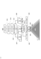
図2は、本開示の実施例1に係る障害物検知装置200のハードウェア構成を示す図である。図2に示す障害物検知装置200は、ステレオ画像に基づいた深度表現、機械学習に基づいた深度表現との2種類の深度表現を結合することにより、近距離の物体及び遠距離の物体の両方について高精度な物体検出及び深度判定を行うための装置である。
なお、本実施例では、第1の深度表現、第2の深度表現、及び第3の深度表現を深度マップとした場合を想定して説明するが、本開示はこれに限定されず、移動体と、当該移動体の周辺に存在する物体までの距離を示すものであれば、異なるデータ構造であってもよい。
FIG. 2 is a diagram showing a hardware configuration of an obstacle detection device 200 according to Example 1 of the present disclosure. The obstacle detection device 200 shown in FIG. 2 combines two types of depth representation: a depth representation based on stereo images and a depth representation based on machine learning. This is a device for highly accurate object detection and depth determination.
Note that this embodiment will be described assuming that the first depth representation, the second depth representation, and the third depth representation are depth maps, but the present disclosure is not limited to this, and A different data structure may be used as long as it indicates the distance to objects existing around the moving object.
図2に示すように、本開示の実施例1に係る障害物検知装置200は、第1のセンサ201、第2のセンサ202、第1の深度表現生成部205、第2の深度表現生成部206、及び第3の深度表現生成部210を主に含む。図2に示す障害物検知装置200に含まれる第1のセンサ201、第2のセンサ202、第1の深度表現生成部205、第2の深度表現生成部206、及び第3の深度表現生成部210は、一体的に構成され、列車等の移動体に配置されてもよく、分散された構成であってもよい。例えば、ある実施形態では、第1のセンサ201及び第2のセンサ202のみを列車等の移動体に配置し、第1の深度表現生成部205、第2の深度表現生成部206、及び第3の深度表現生成部210の機能を、インターネット等の通信ネットワークを介して移動体に接続されている遠隔のサーバ装置等に実施させてもよい。
なお、ここでの列車等の移動体(図示せず)は、鉄道の運行の単位として編成した車両、自動車、モノレール、飛行機、船舶等、任意の移動体であってもよい。
As shown in FIG. 2, the obstacle detection device 200 according to the first embodiment of the present disclosure includes a
Note that the moving object such as a train (not shown) may be any moving object such as a vehicle organized as a unit of railway operation, an automobile, a monorail, an airplane, a ship, or the like.
第1のセンサ201及び第2のセンサ202は、列車等の移動体の周辺を継続的に撮影し、画像を取得する撮影装置である。第1のセンサ201及び第2のセンサ202は、互いに所定の距離を開けて配置され、実質的に同一の撮影範囲を撮影するように構成される。また、第1のセンサ201及び第2のセンサ202の種類は、例えば可視光画像を取得するための可視光カメラ、ステレオカメラ、赤外線カメラ等であってもよい。
図2に示すように、第1のセンサ201及び第2のセンサ202は、第1の画像203及び第2の画像204をそれぞれ取得する。この第1の画像203及び第2の画像204は、センサの種類によっては、RGB画像、赤外線画像、ステレオ画像等、任意の形式の画像であってもよいが、本実施例では、第1の画像203及び第2の画像204のそれぞれが単一のステレオ画像とした場合を想定して説明する。
これらの第1の画像203及び第2の画像204は、後述するように、機械学習に基づく深度表現と、ステレオ画像間の視差に基づく深度表現の生成に用いられる。
The
As shown in FIG. 2, a
These
第1の深度表現生成部205は、第1のセンサ201によって取得された第1の画像203と、第2のセンサ202によって取得された第2の画像204とから生成される視差画像を用いて、第1の深度表現208を生成するための機能部である。ここでの視差画像は、既存の手段によって生成されてもよい。
なお、ここでの第1の深度表現208とは、第1の画像203と、第2の画像204との視差から生成される深度表現であるため、遠距離の物体に関する深度情報の精度が限られているが、近距離の物体に関する深度情報の精度が良好である。
The first depth
Note that the
第2の深度表現生成部206は、第1の画像203を所定の機械学習手法によって処理することにより、第2の深度表現207を生成すると共に、第2の画像204を所定の機械学習手法によって処理することにより、第3の深度表現209を生成するための機能部である。
なお、ここでの第2の深度表現207と、第3の深度表現209とは、第1の画像203と、第2の画像204との視差から生成される第1の深度表現208と異なり、単一の画像に対して所定の機械学習手法を施すことにより得られる深度表現であり、遠距離の物体に関する深度情報の精度が良好である。
The second depth
Note that the
第3の深度表現生成部210は、第1の深度表現208と、第2の深度表現207及び/又は第3の深度表現209とを結合することで、結合深度表現212を生成するための機能部である。
ここでの結合深度表現212とは、遠距離の物体に関する正確な深度情報を示す機械学習に基づいた深度表現である第2の深度表現207及び/又は第3の深度表現209と、近距離の物体に関する正確な深度情報を示すステレオ画像に基づいた深度表現である第1の深度表現208とを結合することで生成され、撮影画像の全範囲について高精度な深度情報を含む深度表現である。
なお、この結合深度表現212は、遠距離の物体に関する正確な深度情報を示す機械学習に基づいた深度表現である第2の深度表現207及び第3の深度表現209のいずれか一方と、近距離の物体に関する正確な深度情報を示すステレオ画像に基づいた深度表現である第1の深度表現208との少なくとも2つの深度表現とから生成することができるが、深度判定の精度を更に向上させる観点から、第1の深度表現208と、第2の深度表現207と、第3の深度表現209との3つの深度表現から生成することが望ましい。
The third depth
The combined
Note that this combined
障害物検出部214とは、第3の深度表現生成部210によって生成される結合深度表現212を用いて、移動体の周辺の障害物に関する障害物情報216を生成し、出力するための機能部である。
ここでの障害物情報216とは、倒木、動物、車、歩行者、火事、水没、レール破断等の、列車の走行を阻止する可能性のある障害物の有無、存在位置、推定移動速度、移動方向、移動体からの距離、カテゴリー(倒木、動物)等、障害物を特徴付ける情報を含む。この障害物情報216は、例えば列車の運行を制御するための遠隔列車運行管理部、列車に内蔵されている列車運行管理部、列車の運転士・乗務員、障害物通知を発した列車とは異なる列車(所定の半径以内の列車等)、又は警察署、消防署、気象庁、企業、機関、団体、個人等、任意の通知先に送信されてもよい。この障害物情報216を受信した通知先は、例えば、列車の運行を制御したり、検出された障害物を処分したりして列車の走行安全性を向上させるための対策を実施してもよい。
The
なお、障害物検知装置200に含まれるそれぞれの機能部は、図1に示すコンピュータシステム300における障害物検出アプリケーション350を構成するソフトウエアモジュールであってもよく、独立した専用ハードウェアデバイスであってもよい。また、上記の機能部は、同一のコンピューティング環境に実施されてもよく、分散されたコンピューティング環境に実施されてもよい。
Note that each functional unit included in the obstacle detection device 200 may be a software module that constitutes the
以上説明したように構成された障害物検知装置200は、遠距離の物体に関する正確な深度情報を示す機械学習に基づいた深度表現(第2の深度表現207及び/又は第3の深度表現209)と、近距離の物体に関する正確な深度情報を示すステレオ画像に基づいた深度表現(第1の深度表現208)とを結合することで、撮影画像の全範囲について高精度な物体検出が可能となる。これにより、列車等の移動体の周辺に存在する障害物を正確に検出することができ、走行の安全性を向上させることができる。
The obstacle detection device 200 configured as described above has a depth representation (
次に、図3を参照して、本開示の実施例1に係る障害物検知方法について説明する。 Next, with reference to FIG. 3, an obstacle detection method according to Example 1 of the present disclosure will be described.
図3は、本開示の実施例1に係る障害物検知方法360の流れの一例を示すフローチャートである。図3に示す障害物検知方法360は、例えば図2を参照して説明した障害物検知装置200によって実施され、移動体の周辺に存在する障害物を検出するための処理である。
FIG. 3 is a flowchart illustrating an example of the flow of an
まず、ステップS361、ステップS362では、第1のセンサ及び第2のセンサ(例えば、図2に示す第1のセンサ201及び第2のセンサ202)のそれぞれは、移動体の周辺を撮影し、第1の画像203及び第2の画像204を取得する。ここでの第1の画像203及び第2の画像204のそれぞれは、移動体の周辺の風景を示す画像である。また、第1の画像203及び第2の画像204は、後述するように、機械学習に基づく深度表現と、ステレオ画像間の視差に基づく深度表現の生成に用いられる。
First, in steps S361 and S362, each of the first sensor and the second sensor (for example, the
次に、ステップS363では、第1の深度表現生成部(例えば、図2に示す第1の深度表現生成部205)は、第1の画像203及び第2の画像204のそれぞれを入力し、既存の手法により、第1の画像203と第2の画像204との視差を示す視差画像を生成した後、当該視差画像を用いて第1の深度表現を生成する。ここでの既存の手法とは、例えばエピポーラ幾何学に基づいた手法であってもよい。このように生成した深度表現は、近距離の物体に関する正確な深度情報を含む。
Next, in step S363, the first depth representation generation unit (for example, the first depth
次に、ステップS364では、第2の深度表現生成部(例えば、図2に示す第2の深度表現生成部206)は、第1の画像203及び第2の画像204のそれぞれを入力し、第1の画像203及び第2の画像204のそれぞれに対して所定の機械学習手法を施すことより、第2の深度表現207及び第3の深度表現209を生成する。
ここでの所定の機械学習手法とは、学習用画像と、(例えばいわゆるStructure From Motion;SFM法によって得られた)当該学習用画像に対応する深度マップとによって訓練される畳み込みニューラルネットワークを用いて、第1の画像203及び第2の画像204に写る物体の特徴量を抽出し、抽出した特徴量に基づいて、画像に写る物体の深度を示す深度表現を生成するための手法である。このように生成した深度表現は、ステレオ画像間の視差に基づいて生成した深度表現に比べて、遠距離の物体に関する正確な深度情報を含む。
ここでのニューラルネットワークは、例えば、第1の画像を入力する入力層と、第1の画像における物体を特徴付けるコンテキスト特徴量を抽出する中間層と、当該コンテキスト特徴量を用いて、第1の画像の画素毎の深度情報を示す前記第1の深度表現を生成し、出力する出力層をから構成されてもよい。また、ここでのコンテキスト特徴量とは、所定の物体を特徴付ける情報であり、例えば色、形状、大きさ、クラス等を含む。
Next, in step S364, the second depth expression generation unit (for example, the second depth
The predetermined machine learning method here is a convolutional neural network that is trained using a learning image and a depth map corresponding to the learning image (obtained, for example, by the so-called Structure From Motion; SFM method). , is a method for extracting feature amounts of objects appearing in the
The neural network here includes, for example, an input layer that inputs a first image, an intermediate layer that extracts a context feature that characterizes an object in the first image, and an intermediate layer that extracts a context feature that characterizes an object in the first image. and an output layer that generates and outputs the first depth representation indicating depth information for each pixel. Further, the context feature amount here is information that characterizes a predetermined object, and includes, for example, color, shape, size, class, and the like.
次に、ステップS365では、第3の深度表現生成部(例えば、図2に示す第3の深度表現生成部210)は、第1の深度表現208と、第2の深度表現207及び・又は第3の深度表現209とを結合することで、結合深度表現212を生成する。
ここでの結合深度表現212とは、遠距離の物体に関する正確な深度情報を示す機械学習に基づいた深度表現である第2の深度表現207及び・又は第3の深度表現209と、近距離の物体に関する正確な深度情報を示すステレオ画像に基づいた深度表現である第1の深度表現208とを結合することで生成され、撮影画像の全範囲について高精度な深度情報を含む深度表現である。
なお、この結合深度表現212は、遠距離の物体に関する正確な深度情報を示す機械学習に基づいた深度表現である第2の深度表現207及び第3の深度表現209のいずれか一方と、近距離の物体に関する正確な深度情報を示すステレオ画像に基づいた深度表現である第1の深度表現208との少なくとも2つの深度表現とから生成することができるが、深度判定の精度を更に向上させる観点から、第1の深度表現208と、第2の深度表現207と、第3の深度表現209との3つの深度表現から生成することが望ましい。また、ここでは、結合深度表現212を生成する際に用いられる深度表現の数は特定に限定されず、4つ以上の深度表現を用いてもよい。
Next, in step S365, the third depth representation generation unit (for example, the third depth
The combined
Note that this combined
次に、ステップS366では、障害物検出部(例えば、図2に示す障害物検出部214)は、第3の深度表現生成部によって生成される結合深度表現212を解析することで、移動体の周辺の障害物に関する障害物情報216を生成し、出力する。上述したように、ここで生成される障害物情報216は、列車の運転士・乗務員、障害物通知を発した列車とは異なる列車(所定の半径以内の列車等)、又は警察署、消防署、気象庁、企業、機関、団体、個人等、任意の通知先に送信されてもよい。
Next, in step S366, the obstacle detection unit (for example, the
以上説明した障害物検知方法360により、遠距離の物体に関する正確な深度情報を示す機械学習に基づいた深度表現(第2の深度表現207又は第3の深度表現209)と、近距離の物体に関する正確な深度情報を示すステレオ画像に基づいた深度表現(第1の深度表現208)とを結合することで、撮影画像の全範囲について高精度な物体検出が可能となる。これにより、列車等の移動体の周辺に存在する障害物を正確に検出することができ、走行の安全性を向上させることができる。
The
次に、図4を参照して、本開示の実施例1に係る結合深度表現を生成する処理について説明する。 Next, with reference to FIG. 4, a process for generating a joint depth representation according to Example 1 of the present disclosure will be described.
図4は、本開示の実施例1に係る結合深度表現を生成する処理(結合深度表現生成処理)400の一例を示すフローチャートである。図4に示す結合深度表現生成処理400は、上述した第3の深度表現生成部(例えば、図3に示す第3の深度表現生成部210)によって実施される処理である。
FIG. 4 is a flowchart illustrating an example of a process for generating a joint depth representation (joint depth representation generation process) 400 according to the first embodiment of the present disclosure. The combined depth
まず、ステップS401、S402、及びS403では、第3の深度表現生成部は、第1の深度表現208、第2の深度表現207、及び第3の深度表現209のそれぞれを、ポイントクラウドへ変換する。ここでのポイントクラウドとは、深度表現における各深度画素(移動体からの距離を示す深度情報を含む画素;「depth pixel」ともいう)を3次元空間に投影した集合である。例えば、ここでは、いわゆる深度マップである第1の深度表現208、第2の深度表現207、及び第3の深度表現209は、ポイントクラウドへ変換されてもよい。ここで、深度マップをポイントクラウドへ変換することにより、後述するグルーピング処理がより容易となる。
First, in steps S401, S402, and S403, the third depth representation generation unit converts each of the
次に、ステップS404では、第3の深度表現生成部は、ステップS402で生成された、第1の深度表現208(ステレオ画像間の視差に基づいて生成された深度表現)に対応するポイントクラウドと、ステップS401で生成された、第2の深度表現207(第1の画像に対して所定の機械学習手法を施すことにより生成した深度表現)に対応するポイントクラウドとを比較することにより、第1の深度表現208と第2の深度表現207との深度の差分を示す深度差分値を計算する。
より具体的には、ステップS404では、第3の深度表現生成部は、所定の物体検出アルゴリズム(406)によって定義されるバウンディングボックスの位置に基づいて、それぞれのポイントクラウドの間で対応する物体をグルーピングした後、それぞれのポイントクラウドでのグルーピングの結果を比較することで、第1の深度表現208と第2の深度表現207との深度の差分を示す深度差分値を計算する。なお、この処理の詳細については後述する。
Next, in step S404, the third depth representation generation unit generates a point cloud corresponding to the first depth representation 208 (a depth representation generated based on the disparity between stereo images) generated in step S402. , by comparing the point cloud corresponding to the second depth representation 207 (the depth representation generated by applying a predetermined machine learning method to the first image) generated in step S401. A depth difference value indicating the difference in depth between the
More specifically, in step S404, the third depth representation generator calculates corresponding objects between the respective point clouds based on the position of the bounding box defined by the predetermined object detection algorithm (406). After grouping, a depth difference value indicating the difference in depth between the
次に、ステップS405では、第3の深度表現生成部は、ステップS402で生成された、第1の深度表現208(ステレオ画像間の視差に基づいて生成された深度表現)に対応するポイントクラウドと、ステップS403で生成された、第3の深度表現209(第2の画像に対して所定の機械学習手法を施すことにより生成した深度表現)に対応するポイントクラウドとを比較することにより、第1の深度表現208と第3の深度表現209との深度の差分を示す深度差分値を計算する。
より具体的には、ステップS405では、第3の深度表現生成部は、所定の物体検出アルゴリズム(406)によって定義されるバウンディングボックスの位置に基づいて、それぞれのポイントクラウドの間で対応する物体をグルーピングした後、それぞれのポイントクラウドでのグルーピングの結果を比較することで、第1の深度表現208と第3の深度表現209との深度の差分を示す深度差分値を計算する。なお、この処理の詳細については後述する。
Next, in step S405, the third depth representation generation unit generates a point cloud corresponding to the first depth representation 208 (a depth representation generated based on the disparity between stereo images) generated in step S402. , by comparing the point cloud corresponding to the third depth representation 209 (the depth representation generated by applying a predetermined machine learning method to the second image) generated in step S403. A depth difference value indicating the difference in depth between the
More specifically, in step S405, the third depth representation generation unit identifies corresponding objects between the respective point clouds based on the position of the bounding box defined by the predetermined object detection algorithm (406). After grouping, a depth difference value indicating the difference in depth between the
次に、ステップS407では、第3の深度表現生成部は、ステップS404及びステップS405で計算された差分値を平均化し、補正値を計算する。ここでの補正値とは、それぞれの深度表現のポイントクラウドの深度を整合させるための値であり、後述するS408で用いられる。 Next, in step S407, the third depth expression generation unit averages the difference values calculated in steps S404 and S405, and calculates a correction value. The correction value here is a value for matching the depth of the point cloud of each depth expression, and is used in S408 described later.
次に、ステップS408では、第3の深度表現生成部は、ステップS407で計算された補正値に基づいて、第2の深度表現207及び第3の深度表現209を補正することで、補正した第2の深度表現207R及び補正した第3の深度表現209Rを生成する。これにより、第2の深度表現及び第3の深度表現の深度の差分が補正され、第2の深度表現207及び第3の深度表現209の深度が互いに整合することとなる。
Next, in step S408, the third depth expression generation unit corrects the
次に、ステップS409では、第3の深度表現生成部は、補正した第2の深度表現207R及び補正した第3の深度表現209Rから、移動体から所定の距離以上に存在する物体の深度情報を遠距離物体深度情報として抽出する。例えば、ここで、第3の深度表現生成部は、第1の深度表現の視野の範囲外に存在する物体の深度情報を遠距離物体深度情報として抽出してもよい。
Next, in step S409, the third depth representation generation unit generates depth information of an object existing at a predetermined distance or more from the moving object from the corrected
次に、ステップS410では、第3の深度表現生成部は、第1の深度表現から、移動体から所定の距離未満に存在する物体の深度情報を示す遠距離物体深度情報を抽出する。例えば、ここで、第3の深度表現生成部は、第1の深度表現の視野の範囲内に存在する物体の深度情報を近距離物体深度情報として抽出してもよい。 Next, in step S410, the third depth representation generation unit extracts, from the first depth representation, long-distance object depth information indicating depth information of an object existing less than a predetermined distance from the moving body. For example, here, the third depth representation generation unit may extract depth information of an object existing within the field of view of the first depth representation as short-distance object depth information.
次に、ステップS411では、第3の深度表現生成部は、ステップS409で抽出した遠距離物体深度情報と、ステップS410で抽出した近距離物体深度情報とを結合することで、上述した結合深度表現を生成する。ここで、遠距離物体深度情報と近距離物体深度情報とを結合する手段として、例えばHigh Pass filtering, HIS transform based image fusion, PCA based image fusion, wavelet transform image fusion, pair-wise spatial frequency matching等、任意の既存の手法を用いてもよい。 Next, in step S411, the third depth representation generation unit combines the long-distance object depth information extracted in step S409 and the near-distance object depth information extracted in step S410, thereby generating the combined depth representation described above. generate. Here, as means for combining long-distance object depth information and short-distance object depth information, for example, High Pass filtering, HIS transform based image fusion, PCA based image fusion, wavelet transform ima are used. ge fusion, pair-wise spatial frequency matching, etc. Any existing technique may be used.
以上説明した結合深度表現生成処理により、遠距離の物体に関する正確な深度情報を示す機械学習に基づいた深度表現(第2の深度表現207又は第3の深度表現209)と、近距離の物体に関する正確な深度情報を示すステレオ画像に基づいた深度表現(第1の深度表現208)とを結合することで、撮影画像の全範囲について高精度な深度情報を有する結合深度表現を生成することができる。また、このような高精度な深度情報を有する結合深度表現に基づいて、物体検出を行うことにより、移動体の周辺に存在する障害物等の物体を確実に判定することができ、移動体の走行安全性を向上させることができる。
Through the combined depth representation generation process described above, a depth representation (
次に、図5を参照して、本開示の実施例1に係るポイントクラウドを用いる処理の具体例について説明する。 Next, with reference to FIG. 5, a specific example of processing using a point cloud according to Example 1 of the present disclosure will be described.
図5は、本開示の実施例1に係るポイントクラウドを用いる処理の具体例を示す図である。図5には、第1の深度表現(ステレオ画像間の視差に基づいて生成された深度表現)に対応するポイントクラウド502と、第2の深度表現(第1の画像に対して所定の機械学習手法を施すことにより生成した深度表現)に対応するポイントクラウド501と、第3の深度表現(第2の画像に対して所定の機械学習手法を施すことにより生成した深度表現)に対応するポイントクラウド503とが示される。これらのポイントクラウド501、502、503は、図4を参照して説明した結合深度表現生成処理400のS401、S402、S403で生成されるポイントクラウドである。
なお、図5を参照して説明する具体例は、図4を参照して説明した結合深度表現生成処理400におけるステップS405、S406に実質的に対応する。
FIG. 5 is a diagram illustrating a specific example of processing using a point cloud according to Example 1 of the present disclosure. FIG. 5 shows a
Note that the specific example described with reference to FIG. 5 substantially corresponds to steps S405 and S406 in the connection depth
上述したように、移動体に設置されている第1のセンサ201及び第2のセンサ202は、設置されている角度によっては、撮影範囲が互いに異なる。そのため、ステレオ画像間の視差に基づいて生成された第1の深度表現に対応するポイントクラウド502と、第1の画像に対して所定の機械学習手法を施すことにより生成した第2の深度表現に対応するポイントクラウド501と、第2の画像に対して所定の機械学習手法を施すことにより生成した第3の深度表現に対応するポイントクラウド503とで、深度の差分が生じると共に、写る物体が異なることがある。
従って、正確な深度情報を取得するためには、ポイントクラウド間の深度の差分を計算し、ポイントクラウドの深度を互いに整合させるための補正を行うことが望ましい。そこで、本実施例では、所定の物体検出アルゴリズムによって定義されるバウンディングボックスを用いて、複数のポイントクラウド間で同一の物体をグルーピング(対応付け)し、これらのグループを比較することでポイントクラウド間の深度差分を計算した後、当該深度差分から得られる補正値を用いてポイントクラウドを補正することで、正確な深度情報を取得することができる。
As described above, the
Therefore, in order to obtain accurate depth information, it is desirable to calculate the difference in depth between point clouds and perform correction to make the depths of the point clouds match each other. Therefore, in this embodiment, by using a bounding box defined by a predetermined object detection algorithm, the same objects are grouped (corresponded) between multiple point clouds, and these groups are compared. After calculating the depth difference, accurate depth information can be obtained by correcting the point cloud using the correction value obtained from the depth difference.
上述したように、第1のセンサ201及び第2のセンサ202の角度や視野のズレ等により、全ての物体が全ての画像・深度表現に写るとは限らない。一例として、第1のセンサ201及び第2のセンサ202によって撮影される場面には、円筒形の第1の障害物と、球体の第2の障害物と、箱型の第3の障害物と、三角形の第4の障害物が実際に存在するとする。ただし、第1のセンサ201及び第2のセンサ202の角度や撮影範囲の制限等により、円筒形の第1の障害物は、ポイントクラウド501において第1の障害物512として写るが、ポイントクラウド502及びポイントクラウド503に写らない。また、三角形の第4の障害物は、ポイントクラウド503において第4の障害物528として写るが、ポイントクラウド501及びポイントクラウド502に写らない。更に、箱型の第3の障害物は、ポイントクラウド501における第3の障害物525として写り、ポイントクラウド503において第3の障害物535として写るが、ポイントクラウド502に写らない(例えば、ステレオカメラの撮影範囲外である)。一方、球体の第2の障害物は、ポイントクラウド501において第2の障害物524として写り、ポイントクラウド502において第2の障害物534として写り、ポイントクラウド503において第2の障害物544として写る。
As described above, not all objects are necessarily reflected in all images and depth representations due to differences in the angles and fields of view of the
図4を参照して説明した結合深度表現生成処理400のS401、S402、S403で深度表現からポイントクラウドの変換が終了した後、第3の深度表現生成部は、所定の物体検出アルゴリズムによって定義されるバウンディングボックス508を用いて、それぞれのポイントクラウドを互いに比較することで、対応する物体(つまり、同一の物体)をグルーピングする。例えば、ここでは、第3の深度表現生成部は、ポイントクラウド501に写る第2の障害物524を、ポイントクラウド502に写る第2の障害物534と、ポイントクラウド503に写る第2の障害物544と対応付けてグルーピングしてもよい。その後、第3の深度表現生成部は、グルーピングした物体のポイントクラウド間の深度差分を示す差分値を計算する。
なお、ここでのバウンディングボックス508は、ポイントクラウドにおける比較対象の領域の範囲を指定するものであり、バウンディングボックス508のサイズと位置は、例えば電柱や線路等の、鉄道環境に存在するものに基づいて設定されてもよい。このバウンディングボックス508を用いることにより、特定の物体に関する正確な深度情報を取得することができる。また、バウンディングボックス508を用いて比較対象となる領域を制限することで、処理に要するコンピューティング資源を抑えることができる。
After the conversion from the depth representation to the point cloud is completed in S401, S402, and S403 of the combined depth
Note that the
ポイントクラウド間の深度差分を示す差分値が計算された後、第3の深度表現生成部は、物体事に計算された差分値を平均化し、補正値とする。上述したように、この補正値は、それぞれの深度表現のポイントクラウドの深度を整合させるための値である。 After the difference value indicating the depth difference between the point clouds is calculated, the third depth expression generation unit averages the difference values calculated for the object and uses it as a correction value. As described above, this correction value is a value for matching the depths of the point clouds of the respective depth expressions.
次に、図6を参照して、本開示の実施例1に係る、深度表現を補正する処理の具体例について説明する。 Next, with reference to FIG. 6, a specific example of the process of correcting depth expression according to the first embodiment of the present disclosure will be described.
図6は、本開示の実施例1に係る、深度表現を補正する処理の具体例を示す図である。図6に示す具体例は、図4を参照して説明した結合深度表現生成処理400におけるステップS404~S406で計算された補正値を用いて、深度表現を補正する処理の一例であり、図4を参照して説明した結合深度表現生成処理400におけるステップS406~S411に実質的に対応する。
FIG. 6 is a diagram illustrating a specific example of processing for correcting depth expression according to Example 1 of the present disclosure. The specific example shown in FIG. 6 is an example of a process of correcting a depth expression using the correction values calculated in steps S404 to S406 in the combined depth
図6には、第2の深度表現207、第3の深度表現209、第1の深度表現208、及び結合深度表現212が示される。上述したように、第1のセンサ201及び第2のセンサ202の角度や視野のズレ等により、全ての物体が全ての画像・深度表現に写るとは限らない。
一例として、第1のセンサ201及び第2のセンサ202によって撮影される場面には、円筒形の第1の障害物と、球体の第2の障害物と、箱型の第3の障害物と、三角形の第4の障害物が実際に存在するとする。ただし、第1のセンサ201及び第2のセンサ202の角度や撮影範囲の制限等により、円筒形の第1の障害物(605・615)が第2の深度表現207に写るが、第3の深度表現209及び第1の深度表現208に写らない。
また、三角形の第4の障害物(607・617)が第3の深度表現209に写るが、第1の深度表現208に写らない。更に、箱型の第3の障害物(609・619、629、639)は、第2の深度表現207及び第3の深度表現209に写るが、第1の深度表現208に写らない。一方、球体の第2の障害物(611・621、631・641、651)は、第2の深度表現207、第3の深度表現209、及び第1の深度表現208に写る。
In FIG. 6, a
As an example, the scene photographed by the
Further, a fourth triangular obstacle (607, 617) appears in the
上述したように、第3の深度表現生成部は、図4を参照して説明した結合深度表現生成処理400におけるステップS404~S406で計算された補正値を用いて、深度表現の深度が整合されるための補正を行うことで、補正した深度表現を生成する。
一例として、第3の深度表現生成部は、図6に示すように、第2の深度表現207において、計算した補正値に基づいて、第1の障害物の深度を605から615に補正し、第2の障害物の深度を611から621に補正し、第3の障害物の深度を609から619に補正する。同様に、第3の深度表現生成部は、図6に示すように、第3の深度表現209において、計算した補正値に基づいて、第2の障害物の深度を631から641に補正し、第3の障害物の深度を629から639に補正し、第4の障害物の深度を607から617に補正する。これにより、検出された物体の深度情報が修正されている、補正した第2の深度表現及び補正した第3の深度表現(図4に示す207R、209R)が得られる。
As described above, the third depth representation generation unit matches the depth of the depth representation using the correction values calculated in steps S404 to S406 in the combined depth
As an example, as shown in FIG. 6, the third depth representation generation unit corrects the depth of the first obstacle from 605 to 615 in the
第2の深度表現及び第3の深度表現が補正された後、第3の深度表現生成部は、補正した第2の深度表現及び補正した第3の深度表現から、移動体から所定の距離以上に存在する物体の深度情報を遠距離物体深度情報として抽出する。例えば、ここで、第3の深度表現生成部は、第1の深度表現の視野の範囲外に存在する物体の深度情報(例えば、第1の障害物の深度情報、第3の障害物の深度情報)を遠距離物体深度情報として抽出してもよい。次に、第3の深度表現生成部は、第1の深度表現から、移動体から所定の距離未満に存在する物体の深度情報を示す遠距離物体深度情報を抽出する。例えば、ここで、第3の深度表現生成部は、第1の深度表現の視野の範囲内に存在する物体(例えば、第2の障害物)の深度情報を近距離物体深度情報として抽出してもよい。 After the second depth representation and the third depth representation are corrected, the third depth representation generation unit generates the corrected second depth representation and the corrected third depth representation at a distance greater than or equal to a predetermined distance from the moving object. The depth information of objects existing in the area is extracted as long-distance object depth information. For example, here, the third depth representation generation unit generates depth information of an object that exists outside the field of view of the first depth representation (for example, depth information of the first obstacle, depth information of the third obstacle, information) may be extracted as long-distance object depth information. Next, the third depth representation generation unit extracts, from the first depth representation, long-distance object depth information indicating depth information of an object existing less than a predetermined distance from the moving object. For example, here, the third depth representation generation unit extracts depth information of an object (for example, a second obstacle) existing within the field of view of the first depth representation as short-distance object depth information. Good too.
次に、第3の深度表現生成部は、抽出した遠距離物体深度情報及び近距離物体深度情報とを結合することで、結合深度表現212を生成する。この結合深度表現212では、第1の障害物、第2の障害物、第3の障害物、及び第4の障害物が正しい深度(625、655、656、657)で表示される。
Next, the third depth representation generation unit generates a combined
次に、図7を参照して、本開示の実施例1に係る結合深度表現生成処理におけるバウンディングボックスについて説明する。 Next, with reference to FIG. 7, a bounding box in the joint depth representation generation process according to Example 1 of the present disclosure will be described.
図7は、本開示の実施例1に係る結合深度表現生成処理400におけるバウンディングボックスの具体例を示す図である。上述したように、バウンディングボックス508は、図4~図5に示すポイントクラウドにおける比較対象の領域の範囲を指定するものであり、バウンディングボックス508のサイズと位置は、例えば電柱や線路等の、鉄道環境に存在するものに基づいて設定されてもよい。
FIG. 7 is a diagram illustrating a specific example of a bounding box in the connection depth
図7に示すように、バウンディングボックス508は、深度が異なる物体(例えば、電柱等)に対して設定されてもよい。その後、第3の深度表現生成部は、バウンディングボックスの位置に基づいて、異なる深度範囲における各物体の深度情報を補正するための補正値を計算する。一例として、第3の深度表現生成部は、深度50メートルの物体に基づいて、10メートルから100メートルの深度範囲に存在する物体の深度情報を補正するための第1の補正値を計算し、深度150メートルの物体に基づいて、100メートルから200メートルの深度範囲に存在する物体の深度情報を補正するための第2の補正値を計算してもよい。
As shown in FIG. 7, bounding
ここでは、深度情報の補正は、1つ又は複数のバウンディングボックスに基づいて行われてもよい。1つのバウンディングボックスの場合には、深度表現における各深度画素(depth pixel)iについて、当該深度画素iの深度情報を補正するための補正値Δriは、以下の数式2によって求められる。
![]()
![]()
従って、深度画素iの深度情報を補正するための補正値Δriを求めた後、深度画素iの補正後の深度depthrは、以下の数式3によって求められる。
![]()
![]()
また、2つのバウンディングボックスの場合には、深度表現において異なる深度範囲に存在する2つの物体(例えば、10メートルから100メートルの深度範囲に存在する第1の物体と100メートルから200メートルの深度範囲に存在する第2の物体)の各深度画素(depth pixel)iについて、当該深度画素iの深度情報を補正するための補正値Δri(第1の物体の補正値をΔr1とし、第2の物体の補正値をΔr2とする)は、以下の数式4によって求められる。
![]()
![]()
第1の物体の補正値Δr1及び第2の物体の補正値Δr2を求めた後、異なる深度範囲での補正値の割合εは、以下の数式5によって求められる。

従って、補正値の割合εを求めた後、深度画素iの補正後の深度depthrは、以下の数式6によって求められる。
![]()
![]()
例えば、一例として、第3の深度表現生成部は、深度50メートルの第1の物体について、補正値Δr1が「-10」メートルであると判定し、深度150メートルの第2の物体について、補正値Δr2が「-30」メートルであると判定した場合、補正値の割合εが「-0.2」となる。従って、第2の深度表現又は第3の深度表現において深度300メートルの物体の補正後の深度depthrは240となる(300*(1-0.2))。 For example, as an example, the third depth expression generation unit determines that the correction value Δr 1 is "-10" meters for a first object at a depth of 50 meters, and for a second object at a depth of 150 meters, When it is determined that the correction value Δr 2 is "-30" meters, the ratio ε of the correction value becomes "-0.2". Therefore, in the second depth representation or the third depth representation, the corrected depth depth r of an object at a depth of 300 meters is 240 (300*(1-0.2)).
次に、図8を参照して、本開示の実施例2に係る障害物検知装置のハードウェア構成について説明する。 Next, with reference to FIG. 8, a hardware configuration of an obstacle detection device according to a second embodiment of the present disclosure will be described.
図8は、本開示の実施例2に係る障害物検知装置800のハードウェア構成を示す図である。図8に示す障害物検知装置800は、図2に示す障害物検知装置200の構成に加えて、LIDAR(Light Detection and Ranging)部814を含む。
このLIDAR部814を用いることにより、移動体の周辺に存在する物体についてより高精度の深度情報を有するポイントクラウド816(「第4の深度表現」ともいう)を取得することができるため、ステレオ画像間の視差に基づいて生成された深度表現である第1の深度表現208を、このポイントクラウド816に基づいて補正することにより、実施例1に示す障害物検知装置200に比べて、更に高精度の障害物検出が可能となる。
なお、本実施例では、第1の深度表現、第2の深度表現、及び第3の深度表現を深度マップとした場合を想定して説明するが、本開示はこれに限定されず、移動体と、当該移動体の周辺に存在する物体までの距離を示すものであれば、異なるデータ構造であってもよい。
FIG. 8 is a diagram showing a hardware configuration of an obstacle detection device 800 according to Example 2 of the present disclosure. Obstacle detection device 800 shown in FIG. 8 includes a LIDAR (Light Detection and Ranging)
By using this
Note that this embodiment will be described assuming that the first depth representation, the second depth representation, and the third depth representation are depth maps, but the present disclosure is not limited to this, and A different data structure may be used as long as it indicates the distance to objects existing around the moving object.
実施例2に係る障害物検知装置800は、ポイントクラウド816を生成するLIDAR部814を含む点以外、実施例1に係る障害物検知装置200と実質的に同様であるため、ここでは、共通の構成についての説明を省略する。
Since the obstacle detection device 800 according to the second embodiment is substantially the same as the obstacle detection device 200 according to the first embodiment except that it includes a
図8に示すように、LIDAR部814は、第1のセンサ201及び第2のセンサ202と共に設置される。ステレオ画像間の視差に基づいて生成された深度表現である第1の深度表現208を、LIDAR部814によって出力されるポイントクラウド816に基づいて補正することで、更に高精度の深度情報を有する、補正した第1の深度表現を生成することが容易となる。
As shown in FIG. 8, the
次に、図9を参照して、本開示の実施例2に係る障害物検知方法について説明する。 Next, with reference to FIG. 9, an obstacle detection method according to Example 2 of the present disclosure will be described.
図9は、本開示の実施例2に係る障害物検知方法960の流れの一例を示すフローチャートである。図9に示す障害物検知方法960は、例えば図8を参照して説明した障害物検知装置800によって実施され、移動体の周辺に存在する障害物を検出するための処理である。
なお、図9に示す障害物検知方法960は、LIDAR部によって取得したポイントクラウドを用いてステレオ画像間の視差に基づいて生成された深度表現である第1の深度表現を補正する点において、上述した図3に示す障害物検知方法360と相違する。この点以外、図9に示す障害物検知方法960は上述した図3に示す障害物検知方法360と実質的に同様であるため、ここでは、共通のステップについての説明を省略する。
FIG. 9 is a flowchart illustrating an example of the flow of an
Note that the
ステップS961では、LIDAR部は、レーザー光を走査し移動体の周辺を照射し、その散乱や反射光を観測することで、移動体周辺環境を示すポイントクラウド816を出力する。上述したように、ここでのポイントクラウド816は、LIDAR部によって取得された移動体周辺の対象物までの距離を示す3次元空間上の深度情報の集合である。
なお、対象物ごとの深度情報の数、分解能は、レーザー光をどのぐらいの間隔で走査するかといった走査方法で決定される。
In step S961, the LIDAR unit scans the laser beam to illuminate the area around the moving object, and observes the scattered and reflected light, thereby outputting a
Note that the number of depth information and resolution for each object are determined by the scanning method, such as how often the laser beam is scanned.
ステップS962では、第1の深度表現生成部は、第1の画像203及び第2の画像204のそれぞれを入力し、既存の手法により、第1の画像203と第2の画像204との視差を示す視差画像を生成した後、当該視差画像を用いて第1の深度表現を生成する。その後、第1の深度表現生成部は、当該第1の深度表現を、ステップS961で生成されたポイントクラウドに基づいて補正することで、補正した第1の深度表現を生成する。
なお、ポイントクラウドに基づいて第1の深度表現を補正する処理の詳細については後述する。
In step S962, the first depth representation generation unit inputs each of the
Note that details of the process of correcting the first depth representation based on the point cloud will be described later.
補正した第1の深度表現が生成された後、第3の深度表現生成部は、補正した第1の深度表現208と、第2の深度表現207又は第3の深度表現209とを結合することで、結合深度表現212を生成する。
このように、ステレオ画像間の視差に基づいて生成された深度表現である第1の深度表現を、このポイントクラウド816に基づいて補正することにより、実施例1に比べて、更に高精度の障害物検出が可能となる。
After the corrected first depth representation is generated, the third depth representation generation unit combines the corrected
In this way, by correcting the first depth representation, which is a depth representation generated based on the parallax between stereo images, based on the
次に、図10を参照して、本開示の実施例2に係る第1の深度表現を補正する処理について説明する。 Next, with reference to FIG. 10, a process for correcting the first depth representation according to Example 2 of the present disclosure will be described.
図10は、本開示の実施例2に係る第1の深度表現208を補正する処理の一例を示す図である。第1の深度表現208を補正する処理は、例えば図8に示す第1の深度表現生成部205によって実施され、更に高精度の深度情報を有する深度表現を生成するための処理である。
FIG. 10 is a diagram illustrating an example of a process for correcting the
図10には、第1の深度表現208が示される。第1の深度表現生成部は、第1の深度表現208における各ポイント(例えば、物体の画素や頂点等)1001について、当該ポイントに対応する(例えば、所定の距離基準未満の)ポイントをポイントクラウド(例えば、図8に示す、LIDAR部814によって生成されたポイントクラウド816)において特定し、深度表現208のポイント1001とポイントクラウドのポイントとの深度の差分を示す差分値を計算する。
その後、第1の深度表現生成部は、各ポイントについて計算した差分値を平均化し、補正値とする。最後に、第1の深度表現生成部は、計算した補正値に基づいて、深度表現208の各ポイント1001を正しい深度1002に移動させることで、補正した第1の深度表現を生成する。
これにより、実施例1に比べて、更に高精度の深度情報を有する深度表現を生成することができるため、より高精度の障害物検出が可能となる。
In FIG. 10, a
Thereafter, the first depth representation generation unit averages the difference values calculated for each point and uses the average as a correction value. Finally, the first depth representation generation unit generates a corrected first depth representation by moving each
As a result, it is possible to generate a depth representation having more accurate depth information than in the first embodiment, so that more accurate obstacle detection is possible.
次に、図11を参照して、本開示の実施例3に係る結合深度表現を生成する処理について説明する。 Next, with reference to FIG. 11, a process for generating a connection depth representation according to Example 3 of the present disclosure will be described.
図11は、本開示の実施例3に係る結合深度表現を生成する処理(結合深度表現生成処理)1100の一例を示すフローチャートである。図11に示す結合深度表現生成処理1100は、上述した第3の深度表現生成部(例えば、図3に示す第3の深度表現生成部210)によって実施される処理である。
図11に示す結合深度表現生成処理1100は、第1の深度表現208、第2の深度表現207、及び第3の深度表現209をポイントクラウドに変換せず、深度表現に対して直接にグルーピングを行う点において、上述した実施例1における結合深度表現生成処理400と異なる。このように、第1の深度表現208、第2の深度表現207、及び第3の深度表現209をポイントクラウドに変換する処理を省略することにより、実施例1に比べてコンピューティング資源を節約することができる。ただし、バウンディングボックスの形式が2次元となるため、3次元のバウンディングボックスによるグルーピングができない。
FIG. 11 is a flowchart illustrating an example of a
The combined depth
また、本実施例では、第1の深度表現、第2の深度表現、及び第3の深度表現を深度マップとした場合を想定して説明するが、本開示はこれに限定されず、移動体と、当該移動体の周辺に存在する物体までの距離を示すものであれば、異なるデータ構造であってもよい。
なお、第1の深度表現208、第2の深度表現207、及び第3の深度表現209をポイントクラウドに変換する処理を省略する点以外、実施例3に係る示す結合深度表現生成処理1100は、実施例1に係る示す結合深度表現生成処理400と実質的に同様であるため、ここでは、共通のステップについての説明を省略する。
Further, in this embodiment, description will be made assuming that the first depth representation, the second depth representation, and the third depth representation are depth maps, but the present disclosure is not limited to this, and the mobile object A different data structure may be used as long as it indicates the distance to objects existing around the moving object.
Note that the combined depth
ステップS1104では、第3の深度表現生成部は、第1の深度表現208(ステレオ画像間の視差に基づいて生成された深度表現)と、第2の深度表現207(第1の画像に対して所定の機械学習手法を施すことにより生成した深度表現)とを比較することにより、第1の深度表現208と第2の深度表現207との深度の差分を示す深度差分値を計算する。
より具体的には、ステップS1104では、第3の深度表現生成部は、所定の物体検出アルゴリズム(406)によって定義されるバウンディングボックスの位置に基づいて、それぞれの深度表現の間で対応する物体をグルーピングした後、それぞれの深度表現でのグルーピングの結果を比較することで、第1の深度表現208と第2の深度表現207との深度の差分を示す深度差分値を計算する。なお、この処理の詳細は、図4~6を参照して説明したため、ここでは省略する。
In step S1104, the third depth expression generation unit generates a first depth expression 208 (a depth expression generated based on the disparity between stereo images) and a second depth expression 207 (a depth expression generated based on the disparity between stereo images). A depth difference value indicating the difference in depth between the
More specifically, in step S1104, the third depth representation generation unit generates corresponding objects between the respective depth representations based on the position of the bounding box defined by the predetermined object detection algorithm (406). After grouping, a depth difference value indicating the difference in depth between the
次に、ステップS1105では、第3の深度表現生成部は、第1の深度表現208(ステレオ画像間の視差に基づいて生成された深度表現)と、第3の深度表現209(第2の画像に対して所定の機械学習手法を施すことにより生成した深度表現)とを比較することにより、第1の深度表現208と第3の深度表現209との深度の差分を示す深度差分値を計算する。
より具体的には、ステップS1105では、第3の深度表現生成部は、所定の物体検出アルゴリズム(406)によって定義されるバウンディングボックスの位置に基づいて、それぞれの深度表現の間で対応する物体をグルーピングした後、それぞれの深度表現でのグルーピングの結果を比較することで、第1の深度表現208と第3の深度表現209との深度の差分を示す深度差分値を計算する。なお、この処理の詳細は、図4~6を参照して説明したため、ここでは省略する。
Next, in step S1105, the third depth representation generation unit generates a first depth representation 208 (a depth representation generated based on the parallax between stereo images) and a third depth representation 209 (a depth representation generated based on the parallax between stereo images). A depth difference value indicating the difference in depth between the
More specifically, in step S1105, the third depth representation generation unit generates corresponding objects between the respective depth representations based on the position of the bounding box defined by the predetermined object detection algorithm (406). After grouping, a depth difference value indicating the difference in depth between the
このように、第1の深度表現208、第2の深度表現207、及び第3の深度表現209をポイントクラウドに変換する処理を省略し、深度表現に対して直接にグルーピングを行うことにより、実施例1に比べてコンピューティング資源を節約することができる。
In this way, by omitting the process of converting the
次に、図12を参照して、本開示の実施例4に係る結合深度表現を生成する処理について説明する。 Next, with reference to FIG. 12, a process for generating a joint depth representation according to Example 4 of the present disclosure will be described.
図12は、本開示の実施例4に係る結合深度表現を生成する処理(結合深度表現生成処理)1200の一例を示すフローチャートである。図12に示す結合深度表現生成処理1200は、上述した第3の深度表現生成部(例えば、図3に示す第3の深度表現生成部210)によって実施される処理である。
図12に示す結合深度表現生成処理1200は、バウンディングボックスによるグルーピングの代わりに、最近傍探索法を用いてグルーピングを行う点において、上述した実施例1における結合深度表現生成処理400と異なる。バウンディングボックスによるグルーピングの代わりに、最近傍探索法を用いてグルーピングを行うことにより、2次元及び3次元のデータを対応しつつ、実施例1に比べてコンピューティング資源を節約することができる。
最近傍探索(英: Nearest neighbor search, NNS)は、ポイントクラウド等のような距離空間における最も近い点を探す解法であり、線形探索や空間分割等の手法を含む。
FIG. 12 is a flowchart illustrating an example of a
The joint depth
Nearest neighbor search (NNS) is a solution method that searches for the closest point in a metric space such as a point cloud, and includes methods such as linear search and space partitioning.
また、本実施例では、第1の深度表現、第2の深度表現、及び第3の深度表現を深度マップとした場合を想定して説明するが、本開示はこれに限定されず、移動体と、当該移動体の周辺に存在する物体までの距離を示すものであれば、異なるデータ構造であってもよい。
なお、図12に示す結合深度表現生成処理1200は、バウンディングボックスによるグルーピングの代わりに、最近傍探索法を用いてグルーピングを行う点以外、実施例4に係る示す結合深度表現生成処理1200は、実施例1に係る示す結合深度表現生成処理400と実質的に同様であるため、ここでは、共通のステップについての説明を省略する。
Further, in this embodiment, description will be made assuming that the first depth representation, the second depth representation, and the third depth representation are depth maps, but the present disclosure is not limited to this, and the mobile object A different data structure may be used as long as it indicates the distance to objects existing around the moving object.
Note that the joint depth
ステップS1204では、第3の深度表現生成部は、ステップS402で生成された、第1の深度表現208(ステレオ画像間の視差に基づいて生成された深度表現)に対応するポイントクラウドと、ステップS401で生成された、第2の深度表現207(第1の画像に対して所定の機械学習手法を施すことにより生成した深度表現)に対応するポイントクラウドとを比較することにより、第1の深度表現208と第2の深度表現207との深度の差分を示す深度差分値を計算する。
より具体的には、ステップS1204では、第3の深度表現生成部は、第1の深度表現208に対応するポイントクラウドと、第2の深度表現207に対応するポイントクラウドとに対して最近傍探索法を施すことにより、これらのポイントクラウド間で最も近い点をグルーピングし、このグルーピングの結果を比較することで、第1の深度表現208と第2の深度表現207との深度の差分を示す深度差分値を計算する。
In step S1204, the third depth representation generation unit generates the point cloud corresponding to the first depth representation 208 (depth representation generated based on the disparity between stereo images) generated in step S402, and the point cloud generated in step S402. By comparing the point cloud corresponding to the second depth representation 207 (the depth representation generated by applying a predetermined machine learning method to the first image) generated in A depth difference value indicating the difference in depth between 208 and the
More specifically, in step S1204, the third depth representation generation unit performs nearest neighbor search on the point cloud corresponding to the
次に、ステップS1205では、第3の深度表現生成部は、ステップS402で生成された、第1の深度表現208(ステレオ画像間の視差に基づいて生成された深度表現)に対応するポイントクラウドと、ステップS403で生成された、第3の深度表現209(第2の画像に対して所定の機械学習手法を施すことにより生成した深度表現)に対応するポイントクラウドとを比較することにより、第1の深度表現208と第3の深度表現209との深度の差分を示す深度差分値を計算する。
より具体的には、ステップS1205では、第3の深度表現生成部は、第1の深度表現208に対応するポイントクラウドと、第3の深度表現209に対応するポイントクラウドとに対して最近傍探索法を施すことにより、これらのポイントクラウド間で最も近い点をグルーピングし、このグルーピングの結果を比較することで、第1の深度表現208と第3の深度表現209との深度の差分を示す深度差分値を計算する。
Next, in step S1205, the third depth representation generation unit generates a point cloud corresponding to the first depth representation 208 (a depth representation generated based on the disparity between stereo images) generated in step S402. , by comparing the point cloud corresponding to the third depth representation 209 (the depth representation generated by applying a predetermined machine learning method to the second image) generated in step S403. A depth difference value indicating the difference in depth between the
More specifically, in step S1205, the third depth representation generation unit performs nearest neighbor search on the point cloud corresponding to the
以上説明した実施例4に係る結合深度表現生成処理1200によれば、バウンディングボックスによるグルーピングの代わりに、最近傍探索法を用いてグルーピングを行うことにより、2次元及び3次元のデータを対応しつつ、実施例1に比べてコンピューティング資源を節約することができる。
According to the joint depth
次に、図13を参照して、本開示の実施例5に係る障害物検知装置のハードウェア構成について説明する。 Next, with reference to FIG. 13, a hardware configuration of an obstacle detection device according to Example 5 of the present disclosure will be described.
図13は、本開示の実施例5に係る障害物検知装置1300のハードウェア構成を示す図である。図13に示す障害物検知装置1300は、ステレオ画像間の視差に基づいて生成された深度表現である第1の深度表現を生成するための第1の深度表現生成部を省略し、LIDAR部814から出力されるポイントクラウド1310を第1の深度表現の代わりに用いる点において、実施例2に係る障害物検知装置800の構成と異なる。
LIDAR部814から出力されるポイントクラウド1310を第1の深度表現の代わりに用いることにより、遠距離の物体についての深度情報の精度が限られている、ステレオ画像間の視差に基づいて生成された深度表現が不要となり、更に高精度の障害物検出が可能となる。
なお、本実施例では、第2の深度表現及び第3の深度表現を深度マップとした場合を想定して説明するが、本開示はこれに限定されず、移動体と、当該移動体の周辺に存在する物体までの距離を示すものであれば、異なるデータ構造であってもよい。
FIG. 13 is a diagram showing a hardware configuration of an
By using the
Note that in this example, description will be made assuming that the second depth representation and the third depth representation are depth maps; however, the present disclosure is not limited to this, and the present disclosure is not limited to this, and A different data structure may be used as long as it indicates the distance to an object located in the area.
なお、実施例5に係る障害物検知装置1300は、LIDAR部814から出力されるポイントクラウド1310を第1の深度表現の代わりに用いる点以外、実施例2に係る障害物検知装置800と実質的に同様であるため、ここでは、共通の構成についての説明を省略する。
Note that the
次に、図14を参照して、本開示の実施例5に係る障害物検知方法について説明する。 Next, with reference to FIG. 14, an obstacle detection method according to Example 5 of the present disclosure will be described.
図14は、本開示の実施例5に係る障害物検知方法1460の流れの一例を示すフローチャートである。図14に示す障害物検知方法1460は、例えば図13を参照して説明した障害物検知装置1300によって実施され、移動体の周辺に存在する障害物を検出するための処理である。
なお、図14に示す障害物検知方法1460は、LIDAR部から出力されるポイントクラウド1310を第1の深度表現の代わりに用いる点において、上述した図3に示す障害物検知方法360と相違する。この点以外、図14に示す障害物検知方法1460は上述した図3に示す障害物検知方法360と実質的に同様であるため、ここでは、共通のステップについての説明を省略する。
FIG. 14 is a flowchart illustrating an example of the flow of an
Note that the
ステップS1461では、LIDAR部は、移動体の周辺を撮影し、撮影した場面を示すポイントクラウド1310を出力する。上述したように、ここでのポイントクラウド1310は、LIDAR部によって取得された移動体周辺の対象物までの距離を示す3次元空間上の深度情報の集合である。
In step S1461, the LIDAR unit photographs the surroundings of the moving object and outputs a
ステップS1462では、第3の深度表現生成部(例えば、図13に示す第3の深度表現生成部210)は、ポイントクラウド1310、第2の深度表現207又は第3の深度表現209とを結合することで、結合深度表現212を生成する。
ここでの結合深度表現212とは、遠距離の物体に関する正確な深度情報を示す機械学習に基づいた深度表現である第2の深度表現207及び・又は第3の深度表現209と、ステレオ画像間の視差に基づいて生成された深度表現より高精度の深度情報を有するポイントクラウドとから生成されるため、例えば実施例1に比べて更に高精度の障害物検出が可能となる。
In step S1462, the third depth representation generation unit (for example, the third depth
The combined
次に、図15を参照して、本開示の実施例5に係る結合深度表現を生成する処理について説明する。 Next, with reference to FIG. 15, a process for generating a joint depth representation according to Example 5 of the present disclosure will be described.
図15は、本開示の実施例5に係る結合深度表現を生成する処理(結合深度表現生成処理)1500の一例を示すフローチャートである。図15に示す結合深度表現生成処理1500は、上述した第3の深度表現生成部(例えば、図13に示す第3の深度表現生成部210)によって実施される処理である。
図15に示す結合深度表現生成処理1500は、LIDAR部から出力されるポイントクラウド1310を第1の深度表現の代わりに用いる点において、上述した図4に示す結合深度表現生成処理400と相違する。この点以外、図15に示す結合深度表現生成処理1500は上述した図4に示す結合深度表現生成処理400と実質的に同様であるため、ここでは、共通のステップについての説明を省略する。
FIG. 15 is a flowchart illustrating an example of a
The combined depth
ステップS1504では、第3の深度表現生成部は、LIDAR部から出力されるポイントクラウド1310と、第2の深度表現207(第1の画像に対して所定の機械学習手法を施すことにより生成した深度表現)とを比較することにより、LIDAR部のポイントクラウド1310と第2の深度表現207との深度の差分を示す深度差分値を計算する。
より具体的には、ステップS1504では、第3の深度表現生成部は、所定の物体検出アルゴリズム(406)によって定義されるバウンディングボックスの位置に基づいて、それぞれのポイントクラウドの間で対応する物体をグルーピングした後、それぞれのポイントクラウドでのグルーピングの結果を比較することで、LIDAR部のポイントクラウド1310と第2の深度表現207との深度の差分を示す深度差分値を計算する。なお、この処理の詳細は、図4~6を参照して説明したため、ここでは省略する。
In step S1504, the third depth representation generation unit generates the
More specifically, in step S1504, the third depth representation generator calculates corresponding objects between the respective point clouds based on the position of the bounding box defined by the predetermined object detection algorithm (406). After grouping, a depth difference value indicating the difference in depth between the
次に、ステップS1505では、第3の深度表現生成部は、LIDAR部から出力されるポイントクラウド1310と、第3の深度表現209(第2の画像に対して所定の機械学習手法を施すことにより生成した深度表現)とを比較することにより、LIDAR部のポイントクラウド1310と第3の深度表現209との深度の差分を示す深度差分値を計算する。
より具体的には、ステップS1505では、第3の深度表現生成部は、所定の物体検出アルゴリズム(406)によって定義されるバウンディングボックスの位置に基づいて、それぞれのポイントクラウドの間で対応する物体をグルーピングした後、それぞれのポイントクラウドでのグルーピングの結果を比較することで、第1の深度表現208と第3の深度表現209との深度の差分を示す深度差分値を計算する。なお、この処理の詳細は、図4~6を参照して説明したため、ここでは省略する。
Next, in step S1505, the third depth representation generation unit generates the
More specifically, in step S1505, the third depth representation generation unit calculates corresponding objects between the respective point clouds based on the position of the bounding box defined by the predetermined object detection algorithm (406). After grouping, a depth difference value indicating the difference in depth between the
このように、LIDAR部814から出力されるポイントクラウド1310を第1の深度表現の代わりに用いることにより、遠距離の物体についての深度情報の精度が限られている、ステレオ画像間の視差に基づいて生成された深度表現が不要となり、例えば上述した実施例1に比べて更に高精度の障害物検出が可能となる。
In this way, by using the
以上、本発明の実施の形態について説明したが、本発明は、上述した実施の形態に限定されるものではなく、本発明の要旨を逸脱しない範囲において種々の変更が可能である。 Although the embodiments of the present invention have been described above, the present invention is not limited to the embodiments described above, and various changes can be made without departing from the gist of the present invention.
200 障害物検知装置
201 第1のセンサ
202 第2のセンサ
203 第1の画像
204 第2の画像
205 第1の深度表現生成部
206 第2の深度表現生成部
207 第2の深度表現
208 第1の深度表現
209 第3の深度表現
210 第3の深度表現生成部
212 結合深度表現
214 障害物検出部
216 障害物情報
200 obstacle detection device
201
Claims (7)
前記障害物検知装置は、
第1のセンサによって取得された第1の画像と、第2のセンサによって取得された第2の画像とから生成される視差画像を用いて、前記移動体と前記移動体の周辺に存在する物体との距離を示す第1の深度表現を生成する第1の深度表現生成部と、
前記第1の画像を所定の機械学習手法によって処理することにより、前記移動体と前記移動体の周辺に存在する物体との距離を示す第2の深度表現を生成する第2の深度表現生成部と、
前記第1の深度表現を第1のポイントクラウドに変換し、
前記第2の深度表現を第2のポイントクラウドに変換し、
所定の物体検出手法によって第1のポイントクラウドにおいて存在する第1の物体を特定し、
前記所定の物体検出手法によって第2のポイントクラウドにおいて存在し、前記第1の物体に対応する第2の物体を特定し、
前記第1の物体と、前記第2の物体とを対応付けて比較することで、前記第1の深度表現と前記第2の深度表現との深度の差分を示す深度差分値を計算し、
前記深度差分値に基づいて、前記第2の深度表現によって示される、前記移動体と前記移動体の周辺に存在する物体との距離を前記第1の深度表現に整合するように補正し、補正した第2の深度表現を生成し、
前記第1の深度表現から、前記移動体から所定の距離未満に存在する物体に関する近距離物体深度情報を抽出し、
前記補正した第2の深度表現から、前記移動体から前記所定の距離以上に存在する物体に関する遠距離物体深度情報を抽出し、
前記近距離物体深度情報と、前記遠距離物体深度情報とを結合することで、
前記第1の深度表現と前記第2の深度表現とに比べて、前記移動体と前記移動体の周辺に存在する物体との距離をより正確に示す結合深度表現を生成する第3の深度表現生成部と、
前記結合深度表現を用いて、前記移動体の周辺の障害物に関する障害物情報を生成し、出力する障害物検出部と、
を含むことを特徴とする障害物検知装置。 An obstacle detection device that detects obstacles around a moving object,
The obstacle detection device includes:
The mobile body and objects existing around the mobile body are determined using a parallax image generated from a first image acquired by a first sensor and a second image acquired by a second sensor. a first depth expression generation unit that generates a first depth expression indicating the distance from the
a second depth expression generation unit that generates a second depth expression indicating a distance between the moving object and objects existing around the moving object by processing the first image using a predetermined machine learning method; and,
converting the first depth representation into a first point cloud;
converting the second depth representation into a second point cloud;
identifying a first object existing in the first point cloud by a predetermined object detection method;
identifying a second object existing in the second point cloud and corresponding to the first object by the predetermined object detection method;
calculating a depth difference value indicating a difference in depth between the first depth representation and the second depth representation by associating and comparing the first object and the second object;
Based on the depth difference value, the distance between the moving body and objects existing around the moving body, which is indicated by the second depth expression, is corrected to match the first depth expression; generate a second depth representation,
extracting short-distance object depth information regarding an object existing less than a predetermined distance from the moving body from the first depth representation;
extracting long-distance object depth information regarding an object existing at a distance greater than or equal to the predetermined distance from the moving object from the corrected second depth representation;
By combining the short-distance object depth information and the long-distance object depth information ,
A third depth representation that generates a combined depth representation that more accurately indicates the distance between the moving object and objects existing around the moving object than the first depth representation and the second depth representation. A generation section,
an obstacle detection unit that uses the combined depth representation to generate and output obstacle information regarding obstacles around the moving body;
An obstacle detection device comprising:
レーザー光を走査し移動体の周辺を照射し、その散乱や反射光を観測することで前記移動体と前記移動体の周辺に存在する物体との距離を示す第4の深度表現を生成するLIDAR(Light Detection and Ranging)部を更に含み、
前記第3の深度表現生成部は、
前記第4の深度表現に基づいて、前記第1の深度表現によって示される、前記移動体と前記移動体の周辺に存在する物体との距離を補正し、補正した第1の深度表現を生成し、
前記深度差分値に基づいて、前記第2の深度表現によって示される、前記移動体と前記移動体の周辺に存在する物体との距離を補正し、
補正した第2の深度表現を生成し、
前記補正した第1の深度表現から、前記移動体から所定の距離未満に存在する物体に関する近距離物体深度情報を抽出し、
前記補正した第2の深度表現から、前記移動体から前記所定の距離以上に存在する物体に関する遠距離物体深度情報を抽出し、
前記近距離物体深度情報と、前記遠距離物体深度情報とを結合することで、前記結合深度表現を生成する、
ことを特徴とする、請求項1に記載の障害物検知装置。 The obstacle detection device includes:
A LIDAR that scans a laser beam, irradiates the area around the moving object, and observes the scattered and reflected light to generate a fourth depth representation indicating the distance between the moving object and objects existing around the moving object. (Light Detection and Ranging) section;
The third depth representation generation unit includes:
Based on the fourth depth representation, a distance between the moving body and an object existing around the moving body, which is indicated by the first depth representation, is corrected to generate a corrected first depth representation. ,
Correcting the distance between the moving body and objects existing around the moving body, which is indicated by the second depth expression, based on the depth difference value,
generating a corrected second depth representation;
extracting short-distance object depth information regarding an object existing less than a predetermined distance from the moving object from the corrected first depth representation;
extracting long-distance object depth information regarding an object existing at a distance greater than or equal to the predetermined distance from the moving object from the corrected second depth representation;
generating the combined depth representation by combining the near-distance object depth information and the far-distance object depth information;
The obstacle detection device according to claim 1 , characterized in that:
ステレオカメラであり、
前記第1の画像及び前記第2の画像は、前記ステレオカメラによって取得されたステレオ画像であり、
前記第1の深度表現は、
前記ステレオ画像によって生成されるステレオ深度マップである、
ことを特徴とする、請求項1に記載の障害物検知装置。 The first sensor and the second sensor are
It is a stereo camera,
The first image and the second image are stereo images acquired by the stereo camera,
The first depth representation is
a stereo depth map generated by the stereo image;
The obstacle detection device according to claim 1, characterized in that:
前記第1の画像と、前記第2の画像とから生成される視差画像を用いて生成した前記第1の深度表現と、
前記第1の画像を所定の機械学習手法によって処理することによって生成した前記第2の深度表現と、
前記第2の画像を所定の機械学習手法によって処理することによって生成した第3の深度表現と、
を結合することで、前記結合深度表現を生成する、
ことを特徴とする、請求項1に記載の障害物検知装置。 The third depth representation generation unit includes:
the first depth representation generated using a parallax image generated from the first image and the second image;
the second depth representation generated by processing the first image using a predetermined machine learning method;
a third depth representation generated by processing the second image using a predetermined machine learning method;
generating the combined depth representation by combining the
The obstacle detection device according to claim 1, characterized in that:
前記第1の画像を入力する入力層と、
前記第1の画像における物体を特徴付けるコンテキスト特徴量を抽出する中間層と、
前記コンテキスト特徴量を用いて、前記第1の画像の画素毎の深度情報を示す前記第1の深度表現を生成し、出力する出力層を含むニューラルネットワークである、
ことを特徴とする、請求項1に記載の障害物検知装置。 The machine learning method is
an input layer that inputs the first image;
an intermediate layer that extracts a context feature characterizing an object in the first image;
a neural network including an output layer that generates and outputs the first depth representation indicating depth information for each pixel of the first image using the context feature;
The obstacle detection device according to claim 1, characterized in that:
前記障害物検知システムにおいて、
前記移動体の周辺を撮影し、第1の画像を取得する第1のセンサと、
前記移動体の周辺を撮影し、第2の画像を取得する第2のセンサと、
障害物を検知する障害物検知装置とが通信ネットワークを介して接続されており、
前記障害物検知装置は、
前記第1のセンサから受信した前記第1の画像と、前記第2のセンサから受信した前記第2の画像とから生成される視差画像を用いて、前記移動体と前記移動体の周辺に存在する物体との距離を示す第1の深度マップを生成する第1の深度表現生成部と、
前記第1の画像を所定の機械学習手法によって処理することにより、前記移動体と前記移動体の周辺に存在する物体との距離を示す第2の深度マップを生成する第2の深度表現生成部と、
前記第1の深度マップを第1のポイントクラウドに変換し、
前記第2の深度マップを第2のポイントクラウドに変換し、
所定の物体検出手法によって第1のポイントクラウドにおいて存在する第1の物体を特定し、
前記所定の物体検出手法によって前記第2のポイントクラウドにおいて存在し、前記第1の物体に対応する第2の物体を特定し、
前記第1の物体と、前記第2の物体とを対応付けて比較することで、前記第1の深度マップと前記第2の深度マップとの深度の差分を示す深度差分値を計算し、
前記深度差分値に基づいて、前記第2の深度マップによって示される、前記移動体と前記移動体の周辺に存在する物体との距離を前記第1の深度マップに整合するように補正し、補正した第2の深度マップを生成し、
前記第1の深度マップから、前記移動体から所定の距離未満に存在する物体に関する近距離物体深度情報を抽出し、
前記補正した第2の深度マップから、前記移動体から前記所定の距離以上に存在する物体に関する遠距離物体深度情報を抽出し、
前記近距離物体深度情報と、前記遠距離物体深度情報とを結合することで、
前記第1の深度マップと前記第2の深度マップとに比べて、前記移動体と前記移動体の周辺に存在する物体との距離をより正確に示す結合深度表現を生成する第3の深度表現生成部と、
前記結合深度表現を用いて、前記移動体の周辺の障害物に関する障害物情報を生成し、所定の通知先に送信する障害物検出部と、
を含むことを特徴とする障害物検知システム。 An obstacle detection system that detects obstacles around a moving object,
In the obstacle detection system,
a first sensor that photographs the surroundings of the moving object and obtains a first image;
a second sensor that photographs the surroundings of the moving object and obtains a second image;
An obstacle detection device that detects obstacles is connected via a communication network.
The obstacle detection device includes:
Using a parallax image generated from the first image received from the first sensor and the second image received from the second sensor, a first depth representation generation unit that generates a first depth map indicating the distance to the object;
a second depth representation generation unit that generates a second depth map indicating a distance between the moving object and objects existing around the moving object by processing the first image using a predetermined machine learning method; and,
converting the first depth map into a first point cloud;
converting the second depth map into a second point cloud;
identifying a first object existing in the first point cloud by a predetermined object detection method;
identifying a second object existing in the second point cloud and corresponding to the first object by the predetermined object detection method;
calculating a depth difference value indicating a difference in depth between the first depth map and the second depth map by associating and comparing the first object and the second object;
Based on the depth difference value, the distance between the moving body and objects existing around the moving body, which is indicated by the second depth map, is corrected to match the first depth map. generate a second depth map,
extracting short-distance object depth information regarding an object existing less than a predetermined distance from the moving object from the first depth map;
extracting, from the corrected second depth map, long-distance object depth information regarding an object existing at a distance greater than or equal to the predetermined distance from the moving body;
By combining the short-distance object depth information and the long-distance object depth information ,
a third depth representation that generates a combined depth representation that more accurately indicates the distance between the moving object and objects existing around the moving object than the first depth map and the second depth map; A generation section,
an obstacle detection unit that uses the connection depth expression to generate obstacle information regarding obstacles around the moving object and sends it to a predetermined notification destination;
An obstacle detection system comprising:
LIDAR部によって取得され、前記移動体と前記移動体の周辺に存在する物体との距離を示す深度表現としてポイントクラウドを生成する工程と、
第1のセンサによって取得される第1の画像を所定の機械学習手法によって処理することにより、前記移動体と前記移動体の周辺に存在する物体との距離を示す深度表現として深度マップを生成する工程と、
所定の物体検出手法によって前記ポイントクラウドにおいて存在する第1の物体を特定する工程と、
前記所定の物体検出手法によって前記深度マップにおいて存在し、前記第1の物体に対応する第2の物体を特定する工程と、
前記第1の物体と、前記第2の物体とを対応付けて比較することで、前記ポイントクラウドと前記深度マップとの深度の差分を示す深度差分値を計算する工程と、
前記深度差分値に基づいて、前記ポイントクラウド及び前記深度マップによって示される、前記移動体と前記移動体の周辺に存在する物体との距離を互いに整合するように前記ポイントクラウド及び前記深度マップのいずれか一方を補正する工程と、
前記ポイントクラウドと、前記深度マップとを結合することで、前記ポイントクラウドと、前記深度マップとに比べて、前記移動体と前記移動体の周辺に存在する物体との距離をより正確に示す結合深度表現を生成する工程と、
前記結合深度表現を用いて、前記移動体の周辺の障害物に関する障害物情報を生成し、出力する工程と、
を含むことを特徴とする障害物検知方法。 An obstacle detection method for detecting obstacles around a moving object, the method comprising:
a step of generating a point cloud as a depth representation obtained by a LIDAR unit and indicating a distance between the moving body and objects existing around the moving body;
A first image acquired by a first sensor is processed by a predetermined machine learning method to generate a depth map as a depth representation indicating the distance between the moving object and objects existing around the moving object. process and
identifying a first object present in the point cloud using a predetermined object detection method;
identifying a second object that is present in the depth map and corresponds to the first object using the predetermined object detection method;
calculating a depth difference value indicating a difference in depth between the point cloud and the depth map by associating and comparing the first object and the second object;
Based on the depth difference value, either the point cloud or the depth map is configured to match the distances between the moving body and objects existing around the moving body, which are indicated by the point cloud and the depth map. a step of correcting one of the two;
Combining the point cloud and the depth map to more accurately indicate the distance between the moving object and objects existing around the moving object than the point cloud and the depth map. a step of generating a depth representation;
generating and outputting obstacle information regarding obstacles around the moving object using the combined depth representation;
An obstacle detection method characterized by comprising:
Priority Applications (3)
| Application Number | Priority Date | Filing Date | Title |
|---|---|---|---|
| JP2020151723A JP7389729B2 (en) | 2020-09-10 | 2020-09-10 | Obstacle detection device, obstacle detection system and obstacle detection method |
| PCT/JP2021/027275 WO2022054422A1 (en) | 2020-09-10 | 2021-07-21 | Obstacle detection device, obstacle detection system, and obstacle detection method |
| EP21866382.1A EP4213128A1 (en) | 2020-09-10 | 2021-07-21 | Obstacle detection device, obstacle detection system, and obstacle detection method |
Applications Claiming Priority (1)
| Application Number | Priority Date | Filing Date | Title |
|---|---|---|---|
| JP2020151723A JP7389729B2 (en) | 2020-09-10 | 2020-09-10 | Obstacle detection device, obstacle detection system and obstacle detection method |
Publications (3)
| Publication Number | Publication Date |
|---|---|
| JP2022045947A JP2022045947A (en) | 2022-03-23 |
| JP2022045947A5 JP2022045947A5 (en) | 2023-03-14 |
| JP7389729B2 true JP7389729B2 (en) | 2023-11-30 |
Family
ID=80632534
Family Applications (1)
| Application Number | Title | Priority Date | Filing Date |
|---|---|---|---|
| JP2020151723A Active JP7389729B2 (en) | 2020-09-10 | 2020-09-10 | Obstacle detection device, obstacle detection system and obstacle detection method |
Country Status (3)
| Country | Link |
|---|---|
| EP (1) | EP4213128A1 (en) |
| JP (1) | JP7389729B2 (en) |
| WO (1) | WO2022054422A1 (en) |
Families Citing this family (3)
| Publication number | Priority date | Publication date | Assignee | Title |
|---|---|---|---|---|
| WO2023195097A1 (en) * | 2022-04-06 | 2023-10-12 | 日本電気株式会社 | Image processing device, non-transitory computer-readable medium having program for same recorded thereon, and method |
| CN114694125B (en) * | 2022-05-31 | 2022-08-26 | 杭州蓝芯科技有限公司 | Data processing method for track foreign matter identification |
| CN115909815B (en) * | 2023-01-06 | 2023-06-06 | 广州通达汽车电气股份有限公司 | Fusion detection method, device, equipment and storage medium based on multivariate data |
Citations (5)
| Publication number | Priority date | Publication date | Assignee | Title |
|---|---|---|---|---|
| JP2004028727A (en) | 2002-06-25 | 2004-01-29 | Fuji Heavy Ind Ltd | Monitoring system, monitoring method, distance correction device for the monitoring system, and distance correction method |
| JP2019125112A (en) | 2018-01-15 | 2019-07-25 | キヤノン株式会社 | Information processor, method for controlling the same, program, and operation control system |
| JP2020020612A (en) | 2018-07-30 | 2020-02-06 | 株式会社リコー | Distance measuring device, method for measuring distance, program, and mobile body |
| JP2020126607A (en) | 2019-01-31 | 2020-08-20 | 株式会社ストラドビジョンStradvision,Inc. | Learning method and learning device for integrating image acquired from camera and point cloud map acquired through corresponding radar or lidar for each convolution stage of neural network, and test method and test device utilizing the same |
| JP2019526878A5 (en) | 2017-09-12 | 2020-10-22 |
Family Cites Families (3)
| Publication number | Priority date | Publication date | Assignee | Title |
|---|---|---|---|---|
| US7786898B2 (en) | 2006-05-31 | 2010-08-31 | Mobileye Technologies Ltd. | Fusion of far infrared and visible images in enhanced obstacle detection in automotive applications |
| US20150381972A1 (en) | 2014-06-30 | 2015-12-31 | Microsoft Corporation | Depth estimation using multi-view stereo and a calibrated projector |
| GB2553782B (en) | 2016-09-12 | 2021-10-20 | Niantic Inc | Predicting depth from image data using a statistical model |
-
2020
- 2020-09-10 JP JP2020151723A patent/JP7389729B2/en active Active
-
2021
- 2021-07-21 WO PCT/JP2021/027275 patent/WO2022054422A1/en active Search and Examination
- 2021-07-21 EP EP21866382.1A patent/EP4213128A1/en active Pending
Patent Citations (5)
| Publication number | Priority date | Publication date | Assignee | Title |
|---|---|---|---|---|
| JP2004028727A (en) | 2002-06-25 | 2004-01-29 | Fuji Heavy Ind Ltd | Monitoring system, monitoring method, distance correction device for the monitoring system, and distance correction method |
| JP2019526878A5 (en) | 2017-09-12 | 2020-10-22 | ||
| JP2019125112A (en) | 2018-01-15 | 2019-07-25 | キヤノン株式会社 | Information processor, method for controlling the same, program, and operation control system |
| JP2020020612A (en) | 2018-07-30 | 2020-02-06 | 株式会社リコー | Distance measuring device, method for measuring distance, program, and mobile body |
| JP2020126607A (en) | 2019-01-31 | 2020-08-20 | 株式会社ストラドビジョンStradvision,Inc. | Learning method and learning device for integrating image acquired from camera and point cloud map acquired through corresponding radar or lidar for each convolution stage of neural network, and test method and test device utilizing the same |
Also Published As
| Publication number | Publication date |
|---|---|
| WO2022054422A1 (en) | 2022-03-17 |
| EP4213128A1 (en) | 2023-07-19 |
| JP2022045947A (en) | 2022-03-23 |
Similar Documents
| Publication | Publication Date | Title |
|---|---|---|
| JP7389729B2 (en) | Obstacle detection device, obstacle detection system and obstacle detection method | |
| US11567496B2 (en) | Method and apparatus for optimizing scan data and method and apparatus for correcting trajectory | |
| WO2020102944A1 (en) | Point cloud processing method and device and storage medium | |
| CN110826499A (en) | Object space parameter detection method and device, electronic equipment and storage medium | |
| US11455806B2 (en) | System and method for free space estimation | |
| US11120280B2 (en) | Geometry-aware instance segmentation in stereo image capture processes | |
| JP2006252473A (en) | Obstacle detector, calibration device, calibration method and calibration program | |
| KR102167835B1 (en) | Apparatus and method of processing image | |
| JP2022045947A5 (en) | ||
| CN112346073A (en) | Dynamic vision sensor and laser radar data fusion method | |
| US20220301277A1 (en) | Target detection method, terminal device, and medium | |
| WO2021114773A1 (en) | Target detection method, device, terminal device, and medium | |
| WO2021114776A1 (en) | Object detection method, object detection device, terminal device, and medium | |
| US11842440B2 (en) | Landmark location reconstruction in autonomous machine applications | |
| US20230138487A1 (en) | An Environment Model Using Cross-Sensor Feature Point Referencing | |
| CN114692720A (en) | Image classification method, device, equipment and storage medium based on aerial view | |
| JP2007233440A (en) | On-vehicle image processor | |
| KR102003387B1 (en) | Method for detecting and locating traffic participants using bird's-eye view image, computer-readerble recording medium storing traffic participants detecting and locating program | |
| WO2021114775A1 (en) | Object detection method, object detection device, terminal device, and medium | |
| Xiong et al. | A 3d estimation of structural road surface based on lane-line information | |
| CN113281770A (en) | Coordinate system relation obtaining method and device | |
| WO2018120932A1 (en) | Method and apparatus for optimizing scan data and method and apparatus for correcting trajectory | |
| WO2024018726A1 (en) | Program, method, system, road map, and road map creation method | |
| US20230245362A1 (en) | Image processing device, image processing method, and computer-readable medium | |
| CN115909274A (en) | Automatic driving-oriented dynamic obstacle detection method |
Legal Events
| Date | Code | Title | Description |
|---|---|---|---|
| A521 | Request for written amendment filed |
Free format text: JAPANESE INTERMEDIATE CODE: A523 Effective date: 20230303 |
|
| A621 | Written request for application examination |
Free format text: JAPANESE INTERMEDIATE CODE: A621 Effective date: 20230303 |
|
| TRDD | Decision of grant or rejection written | ||
| A01 | Written decision to grant a patent or to grant a registration (utility model) |
Free format text: JAPANESE INTERMEDIATE CODE: A01 Effective date: 20231107 |
|
| A61 | First payment of annual fees (during grant procedure) |
Free format text: JAPANESE INTERMEDIATE CODE: A61 Effective date: 20231117 |
|
| R150 | Certificate of patent or registration of utility model |
Ref document number: 7389729 Country of ref document: JP Free format text: JAPANESE INTERMEDIATE CODE: R150 |