KR20170022462A - Over head console for automobile - Google Patents
Over head console for automobile Download PDFInfo
- Publication number
- KR20170022462A KR20170022462A KR1020150117471A KR20150117471A KR20170022462A KR 20170022462 A KR20170022462 A KR 20170022462A KR 1020150117471 A KR1020150117471 A KR 1020150117471A KR 20150117471 A KR20150117471 A KR 20150117471A KR 20170022462 A KR20170022462 A KR 20170022462A
- Authority
- KR
- South Korea
- Prior art keywords
- storage case
- console
- console body
- coupled
- magnet
- Prior art date
Links
Images


Classifications
-
- B—PERFORMING OPERATIONS; TRANSPORTING
- B60—VEHICLES IN GENERAL
- B60R—VEHICLES, VEHICLE FITTINGS, OR VEHICLE PARTS, NOT OTHERWISE PROVIDED FOR
- B60R7/00—Stowing or holding appliances inside vehicle primarily intended for personal property smaller than suit-cases, e.g. travelling articles, or maps
- B60R7/04—Stowing or holding appliances inside vehicle primarily intended for personal property smaller than suit-cases, e.g. travelling articles, or maps in driver or passenger space, e.g. using racks
-
- B—PERFORMING OPERATIONS; TRANSPORTING
- B60—VEHICLES IN GENERAL
- B60Q—ARRANGEMENT OF SIGNALLING OR LIGHTING DEVICES, THE MOUNTING OR SUPPORTING THEREOF OR CIRCUITS THEREFOR, FOR VEHICLES IN GENERAL
- B60Q3/00—Arrangement of lighting devices for vehicle interiors; Lighting devices specially adapted for vehicle interiors
- B60Q3/50—Mounting arrangements
- B60Q3/51—Mounting arrangements for mounting lighting devices onto vehicle interior, e.g. onto ceiling or floor
-
- E—FIXED CONSTRUCTIONS
- E05—LOCKS; KEYS; WINDOW OR DOOR FITTINGS; SAFES
- E05B—LOCKS; ACCESSORIES THEREFOR; HANDCUFFS
- E05B83/00—Vehicle locks specially adapted for particular types of wing or vehicle
- E05B83/28—Locks for glove compartments, console boxes, fuel inlet covers or the like
- E05B83/32—Locks for glove compartments, console boxes, fuel inlet covers or the like for console boxes, e.g. between passenger seats
-
- B—PERFORMING OPERATIONS; TRANSPORTING
- B60—VEHICLES IN GENERAL
- B60R—VEHICLES, VEHICLE FITTINGS, OR VEHICLE PARTS, NOT OTHERWISE PROVIDED FOR
- B60R11/00—Arrangements for holding or mounting articles, not otherwise provided for
- B60R2011/0001—Arrangements for holding or mounting articles, not otherwise provided for characterised by position
- B60R2011/0003—Arrangements for holding or mounting articles, not otherwise provided for characterised by position inside the vehicle
- B60R2011/0007—Mid-console
-
- B—PERFORMING OPERATIONS; TRANSPORTING
- B60—VEHICLES IN GENERAL
- B60R—VEHICLES, VEHICLE FITTINGS, OR VEHICLE PARTS, NOT OTHERWISE PROVIDED FOR
- B60R11/00—Arrangements for holding or mounting articles, not otherwise provided for
- B60R2011/0001—Arrangements for holding or mounting articles, not otherwise provided for characterised by position
- B60R2011/0003—Arrangements for holding or mounting articles, not otherwise provided for characterised by position inside the vehicle
- B60R2011/0028—Ceiling, e.g. roof rails
-
- B—PERFORMING OPERATIONS; TRANSPORTING
- B60—VEHICLES IN GENERAL
- B60R—VEHICLES, VEHICLE FITTINGS, OR VEHICLE PARTS, NOT OTHERWISE PROVIDED FOR
- B60R11/00—Arrangements for holding or mounting articles, not otherwise provided for
- B60R2011/0042—Arrangements for holding or mounting articles, not otherwise provided for characterised by mounting means
- B60R2011/0049—Arrangements for holding or mounting articles, not otherwise provided for characterised by mounting means for non integrated articles
- B60R2011/005—Connection with the vehicle part
- B60R2011/0057—Connection with the vehicle part using magnetic means
Abstract
Description
BACKGROUND OF THE INVENTION 1. Field of the Invention [0002] The present invention relates to an overhead console for a vehicle, and more particularly, to an overhead console for a vehicle having few limitations on a mounting position according to a type of vehicle or an internal structure thereof and having excellent space utilization.
The overhead console refers to a room lamp box or the like which is a structure installed in a roof of a vehicle interior. Particularly, the overhead console installed on the upper side of the front seat of the vehicle is provided with not only a room lamp but also a storage case for storing glasses or sunglasses, thereby enhancing convenience.
1 is a sectional view showing a conventional overhead console.
1, the conventional overhead console includes a console body 1 having a lamp 2 on its outer side and a receiving portion 3 on its inner side and an opening 5 formed in the head lining 4, And is fixed to the roof rail 7 of the roof panel 6. The head lining 4 is a structure to be mounted on the roof panel 6 of the vehicle, and functions as a heat insulation, a sound insulation, a noise absorption in a room, .
In the console body 1, the
However, in such a conventional overhead console for a vehicle, the
SUMMARY OF THE INVENTION The present invention has been made in view of the above problems, and it is an object of the present invention to provide a vehicle overhead console capable of improving space utilization and durability by improving the opening and closing structure of a storage case having a storage room to a translational motion structure The purpose is to provide.
In order to solve the above-mentioned problems, the overhead console for a vehicle according to the present invention comprises a console body mounted on a vehicle, the console body having a receiving portion and an opening portion connected to the receiving portion, and a storage room in which the article can be stored And a storage case which is embedded in the console body or installed to be able to translationally move in a receiving portion of the console body so as to be drawn out to the outside of the console body through an opening of the console body.
The overhead console for a vehicle according to the present invention may include a guide groove provided in one of the console body and the storage case in the direction of translational movement of the storage case and the guide groove formed in the guide groove in order to guide the storage case in parallel with the guide groove, And a guide protrusion provided on the other of the console body and the storage case so as to be slidable.
The overhead console for a vehicle according to the present invention includes a spring installed in a receiving portion of the console body to apply an elastic force to the storage case in a direction of being drawn out to the outside of the console body, And a locking mechanism installed in the receiving portion of the console body so as to be coupled with the storage case to fix the storage case in a state buried in the console body.
The overhead console for a vehicle according to the present invention includes a damping mechanism installed on at least one of the console body and the storage case so as to damp the movement of the storage case protruding to the outside of the console body under the elastic force of the spring .
The damping mechanism may include a first magnet coupled to the console body and a second magnet coupled to the storage case so that a repulsive force acts on the first magnet.
Wherein the housing case includes a case body provided inside the housing chamber and a pair of wings provided on both sides of the case body so as to protrude outwardly, And a pair of the first magnets may be coupled to the console body so as to face the pair of second magnets, respectively.
The overhead console for a vehicle according to the present invention may further include a guide groove provided in the console body in the direction of translational movement of the storage case and a guide groove formed in the console body so as to be slidably inserted into the guide groove for guiding the storage case in parallel with the guide groove The second magnet may be coupled to the guide protrusion, and the first magnet may be coupled to the console body so as to face the second magnet.
The overhead console for a vehicle according to the present invention may further include a guide groove provided in the storage case in the direction of translational movement of the storage case and a guide groove formed in the guide groove to guide the storage case in parallel with the guide groove, The first magnet may be coupled to the guide protrusion, and the second magnet may be coupled to the storage case to face the first magnet.
The storage case may further include a fixing protrusion protruding toward the locking mechanism so that at least a part thereof can be inserted into the locking mechanism, and the spring may be coupled to the storage case at one end thereof so as to be spaced apart from the fixing protrusion .
The storage case may further include a fixing protrusion protruding toward the locking mechanism so as to be inserted into the locking mechanism, wherein the spring has a coil spring structure in which the locking mechanism and the fixing protrusion can be located inside And one end thereof can be coupled to the storage case.
The overhead console for a vehicle according to the present invention having the above-described structure is configured such that the storage case is formed by a translational movement type pull-out structure. Thus, compared with the conventional overhead console for a rotary type vehicle, Space utilization can be increased. Further, locking means such as fixing protrusions for fixing the storage case in a buried state can be provided so as not to be exposed to the outside, thereby increasing the degree of design freedom. Also, the durability can be increased by the stable movement of the storage case.
1 is a cross-sectional view schematically showing a conventional overhead console for a vehicle.
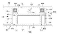
2 is a cross-sectional view schematically showing an overhead console for a vehicle according to an embodiment of the present invention.
FIG. 3 illustrates a state in which the storage case of the overhead console for a vehicle is taken out according to an embodiment of the present invention.
4 is a cross-sectional view schematically showing an overhead console for a vehicle according to another embodiment of the present invention.
5 is a plan view showing an overhead console for a vehicle according to another embodiment of the present invention.
FIG. 6 illustrates a state in which the storage case of the overhead console for a vehicle is taken out according to another embodiment of the present invention.
7 to 9 are sectional views schematically showing various modifications of the overhead console for a vehicle according to the present invention.
Hereinafter, an overheat console for a vehicle according to the present invention will be described with reference to the drawings.
FIG. 2 is a cross-sectional view schematically showing an overhead console for a vehicle according to an embodiment of the present invention, and FIG. 3 illustrates a state in which a storage case of the overhead console for a vehicle is taken out according to an embodiment of the present invention.
2 and 3, the
The
The
A
The
Although the pair of
When the driver presses the
The
The pair of
3, when the
As described above, the
Also, in the
The
4 is a cross-sectional view schematically showing an overhead console for a vehicle according to another embodiment of the present invention. FIG. 5 is a plan view of an overhead console for a vehicle according to another embodiment of the present invention. FIG. 7 is a view showing a state in which the storage case of the overhead console for a vehicle according to another embodiment is taken out.
4 to 6, the
One end of the
The
Also, the
7 to 9 are sectional views schematically showing various modifications of the overhead console for a vehicle according to the present invention.
7 includes a
The
The
One end of the
The damping
The
A pair of
The
The
The
One end of the
The damping
The
The
9 includes a
The
The
One end of the
The damping
The vehicle overhead console 500 is configured such that when the
The overhead console 500 for a vehicle according to the present embodiment is configured such that the
As described above, the overhead console for a vehicle according to the present invention has a structure in which a storage case having a storage compartment is coupled to a console body installed on a vehicle so as to be translationally moved and drawn out from the console body or embedded in the console body Various configurations are possible.
For example, although the figure shows a structure in which a magnet coupled to a console body and a magnet coupled to a housing case are configured to have a repulsive force acting on each other, a damping mechanism for damping the movement of the storage case when the storage case is taken out , The damping mechanism can be changed to another structure having other components than the magnet.
Also, although the figure shows that the storage case is guided to be linearly moved by the guide groove and the guide protrusion, guide means of another structure for guiding the translation of the storage case may be provided.
The foregoing description is merely illustrative of the technical idea of the present invention, and various changes and modifications may be made by those skilled in the art without departing from the essential characteristics of the present invention. Therefore, the embodiments disclosed in the present invention are intended to illustrate rather than limit the scope of the present invention, and the scope of the technical idea of the present invention is not limited by these embodiments. The scope of protection of the present invention should be construed according to the following claims, and all technical ideas within the scope of equivalents should be construed as falling within the scope of the present invention.
10 ...
100 to 500 ...
111, 311, 411, 511 ...
113, 313, 413, 513 ... accommodating
120, 320, 420, 540 ... guide grooves
130, 330, 430, 530 ... storage case
131, 331, 431, 531 ...
133, 333 ...
140, 340, 440, 520 ... Guide projections
150, 210, 350, 450, 550 ...
170, 370, 470, 570 ... damping
172, 372, 472, 572 ... second magnet
Claims (10)
And a housing chamber in which the article can be housed and is installed to be able to translate in the receiving portion of the console body so as to be embedded into the console body or drawn out to the outside of the console body through the opening of the console body And a storage case for storing the overhead console.
A guide groove provided in one of the console body and the storage case in a direction of translational movement of the storage case; And
And a guide protrusion provided on the other of the console body and the storage case so as to be slidably inserted into the guide groove to guide the storage case in parallel with the guide groove. console.
A spring installed in a receiving portion of the console body to apply an elastic force to the storage case in a direction drawn out to the outside of the console body; And
And a locking mechanism coupled to the storage case in a state where the storage case is housed in the receiving portion of the console body and installed in the receiving portion of the console body so as to fix the storage case in a state buried in the console body The overhead console for a vehicle.
And a damping mechanism installed on at least one of the console body and the storage case so as to damp the movement of the storage case protruding to the outside of the console body under the elastic force of the spring. Overhead console.
Wherein the damping mechanism includes a first magnet coupled to the console body, and a second magnet coupled to the storage case to apply a repulsive force to the first magnet.
Wherein the storage case includes a case body having the storage chamber inside and a pair of wings provided on both sides of the case body so as to protrude outward,
Wherein a pair of the second magnets is coupled to a pair of wing portions of the storage case respectively and a pair of the first magnets is coupled to the console body so as to face the pair of second magnets, Overhead console.
A guide groove provided in the console body in the direction of translational movement of the storage case; And
And a guide protrusion provided on the storage case so as to be slidably inserted into the guide groove to guide the storage case in parallel with the guide groove,
Wherein the second magnet is coupled to the guide protrusion and the first magnet is coupled to the console body to face the second magnet.
A guide groove provided in the storage case in a direction of translation of the storage case; And
Further comprising guide protrusions provided on the console body so as to be inserted into the guide grooves and move relative to each other to guide the storage case in parallel with the guide grooves,
Wherein the first magnet is coupled to the guide projection, and the second magnet is coupled to the storage case to face the first magnet.
The storage case may further include a fixing protrusion protruding toward the locking mechanism so that at least a portion thereof can be inserted into the locking mechanism,
Wherein one end of the spring is coupled to the storage case so as to be spaced apart from the fixing protrusion.
The storage case further comprises a fixing protrusion protruding toward the locking mechanism so as to be inserted into the locking mechanism,
Wherein the spring has a coil spring structure in which the locking mechanism and the fixing protrusion can be located inside thereof, and one end of the spring is coupled to the housing case.
Priority Applications (1)
| Application Number | Priority Date | Filing Date | Title |
|---|---|---|---|
| KR1020150117471A KR20170022462A (en) | 2015-08-20 | 2015-08-20 | Over head console for automobile |
Applications Claiming Priority (1)
| Application Number | Priority Date | Filing Date | Title |
|---|---|---|---|
| KR1020150117471A KR20170022462A (en) | 2015-08-20 | 2015-08-20 | Over head console for automobile |
Publications (1)
| Publication Number | Publication Date |
|---|---|
| KR20170022462A true KR20170022462A (en) | 2017-03-02 |
Family
ID=58427121
Family Applications (1)
| Application Number | Title | Priority Date | Filing Date |
|---|---|---|---|
| KR1020150117471A KR20170022462A (en) | 2015-08-20 | 2015-08-20 | Over head console for automobile |
Country Status (1)
| Country | Link |
|---|---|
| KR (1) | KR20170022462A (en) |
Cited By (5)
| Publication number | Priority date | Publication date | Assignee | Title |
|---|---|---|---|---|
| KR20200024611A (en) | 2018-08-28 | 2020-03-09 | (주)대한솔루션 | Jig for fixing ohc plat of headliner |
| KR102130293B1 (en) | 2019-02-21 | 2020-07-09 | (주)대한솔루션 | Ohc bracket for vehicle |
| KR20200127066A (en) | 2019-04-30 | 2020-11-10 | (주)대한솔루션 | Lamp for mounting on headliner of vehicle to decrease bsr |
| KR20200134366A (en) | 2019-05-21 | 2020-12-02 | (주)대한솔루션 | Ohc bracket mounted on headliner for vehicle |
| KR20210107193A (en) | 2020-02-21 | 2021-09-01 | (주)대한솔루션 | Ohc mounting bracket of headliner for vehicle |
Citations (3)
| Publication number | Priority date | Publication date | Assignee | Title |
|---|---|---|---|---|
| KR100570185B1 (en) | 2004-04-30 | 2006-04-12 | 현대자동차주식회사 | Over head console for automobile |
| KR100726500B1 (en) | 2006-02-03 | 2007-06-11 | 현대자동차주식회사 | Sunglass case of vehicle |
| KR100868155B1 (en) | 2007-12-11 | 2008-11-12 | 지엠대우오토앤테크놀로지주식회사 | Sunglass case locking device using for vehicle |
-
2015
- 2015-08-20 KR KR1020150117471A patent/KR20170022462A/en unknown
Patent Citations (3)
| Publication number | Priority date | Publication date | Assignee | Title |
|---|---|---|---|---|
| KR100570185B1 (en) | 2004-04-30 | 2006-04-12 | 현대자동차주식회사 | Over head console for automobile |
| KR100726500B1 (en) | 2006-02-03 | 2007-06-11 | 현대자동차주식회사 | Sunglass case of vehicle |
| KR100868155B1 (en) | 2007-12-11 | 2008-11-12 | 지엠대우오토앤테크놀로지주식회사 | Sunglass case locking device using for vehicle |
Cited By (5)
| Publication number | Priority date | Publication date | Assignee | Title |
|---|---|---|---|---|
| KR20200024611A (en) | 2018-08-28 | 2020-03-09 | (주)대한솔루션 | Jig for fixing ohc plat of headliner |
| KR102130293B1 (en) | 2019-02-21 | 2020-07-09 | (주)대한솔루션 | Ohc bracket for vehicle |
| KR20200127066A (en) | 2019-04-30 | 2020-11-10 | (주)대한솔루션 | Lamp for mounting on headliner of vehicle to decrease bsr |
| KR20200134366A (en) | 2019-05-21 | 2020-12-02 | (주)대한솔루션 | Ohc bracket mounted on headliner for vehicle |
| KR20210107193A (en) | 2020-02-21 | 2021-09-01 | (주)대한솔루션 | Ohc mounting bracket of headliner for vehicle |
Similar Documents
| Publication | Publication Date | Title |
|---|---|---|
| KR20170022462A (en) | Over head console for automobile | |
| KR101259457B1 (en) | retainer having damper member for slinding apparatus | |
| US20120090244A1 (en) | Moving mechanism of movable body | |
| US11255114B2 (en) | Locking device and sliding door with locking device | |
| KR102306955B1 (en) | Refrigerator | |
| KR101114477B1 (en) | sliding apparatus with self-closing apparatus | |
| JP2011524478A (en) | sliding door | |
| US20130014343A1 (en) | Slide assist device | |
| EP3786407B1 (en) | Bidirectional damper and shower door assembly | |
| CN109476251B (en) | Tray for automobile | |
| KR20110010818A (en) | Sliding assist mechanism | |
| KR101559676B1 (en) | Damping apparatus for slider | |
| CN104442589B (en) | The glove box assembly of a kind of automobile and automobile | |
| JP2013082419A (en) | Vehicle storage device | |
| JP2016520741A (en) | Sliding door guide assembly, sliding door, and furniture | |
| CN204296593U (en) | A kind of glove box assembly of automobile and automobile | |
| KR20150002639U (en) | Cup holder | |
| JP5105629B2 (en) | Sliding assist mechanism and pull-in unit | |
| US10842267B2 (en) | Movement mechanism for a guidance system | |
| JP2014527438A (en) | Device for retracting movable furniture parts to an intermediate position | |
| KR101844916B1 (en) | Car door trim | |
| CN219989119U (en) | Storage box and cover body thereof | |
| KR101823383B1 (en) | A glove box | |
| KR200469469Y1 (en) | Glove Lamp Switch for Vehicle | |
| KR101822533B1 (en) | apparatus |