KR20170016247A - Tag for power supply control and method for controlling power supply in sleep mode by using the tag - Google Patents
Tag for power supply control and method for controlling power supply in sleep mode by using the tag Download PDFInfo
- Publication number
- KR20170016247A KR20170016247A KR1020150109732A KR20150109732A KR20170016247A KR 20170016247 A KR20170016247 A KR 20170016247A KR 1020150109732 A KR1020150109732 A KR 1020150109732A KR 20150109732 A KR20150109732 A KR 20150109732A KR 20170016247 A KR20170016247 A KR 20170016247A
- Authority
- KR
- South Korea
- Prior art keywords
- tag
- power supply
- mode
- supply control
- security
- Prior art date
Links
Images

Classifications
-
- G—PHYSICS
- G06—COMPUTING; CALCULATING OR COUNTING
- G06K—GRAPHICAL DATA READING; PRESENTATION OF DATA; RECORD CARRIERS; HANDLING RECORD CARRIERS
- G06K19/00—Record carriers for use with machines and with at least a part designed to carry digital markings
- G06K19/06—Record carriers for use with machines and with at least a part designed to carry digital markings characterised by the kind of the digital marking, e.g. shape, nature, code
- G06K19/067—Record carriers with conductive marks, printed circuits or semiconductor circuit elements, e.g. credit or identity cards also with resonating or responding marks without active components
- G06K19/07—Record carriers with conductive marks, printed circuits or semiconductor circuit elements, e.g. credit or identity cards also with resonating or responding marks without active components with integrated circuit chips
- G06K19/0701—Record carriers with conductive marks, printed circuits or semiconductor circuit elements, e.g. credit or identity cards also with resonating or responding marks without active components with integrated circuit chips at least one of the integrated circuit chips comprising an arrangement for power management
- G06K19/0702—Record carriers with conductive marks, printed circuits or semiconductor circuit elements, e.g. credit or identity cards also with resonating or responding marks without active components with integrated circuit chips at least one of the integrated circuit chips comprising an arrangement for power management the arrangement including a battery
- G06K19/0703—Record carriers with conductive marks, printed circuits or semiconductor circuit elements, e.g. credit or identity cards also with resonating or responding marks without active components with integrated circuit chips at least one of the integrated circuit chips comprising an arrangement for power management the arrangement including a battery the battery being onboard of a handheld device, e.g. a smart phone or PDA
-
- H—ELECTRICITY
- H04—ELECTRIC COMMUNICATION TECHNIQUE
- H04W—WIRELESS COMMUNICATION NETWORKS
- H04W52/00—Power management, e.g. TPC [Transmission Power Control], power saving or power classes
- H04W52/02—Power saving arrangements
- H04W52/0209—Power saving arrangements in terminal devices
- H04W52/0251—Power saving arrangements in terminal devices using monitoring of local events, e.g. events related to user activity
- H04W52/0254—Power saving arrangements in terminal devices using monitoring of local events, e.g. events related to user activity detecting a user operation or a tactile contact or a motion of the device
-
- H—ELECTRICITY
- H04—ELECTRIC COMMUNICATION TECHNIQUE
- H04W—WIRELESS COMMUNICATION NETWORKS
- H04W52/00—Power management, e.g. TPC [Transmission Power Control], power saving or power classes
- H04W52/02—Power saving arrangements
- H04W52/0209—Power saving arrangements in terminal devices
- H04W52/0261—Power saving arrangements in terminal devices managing power supply demand, e.g. depending on battery level
- H04W52/0274—Power saving arrangements in terminal devices managing power supply demand, e.g. depending on battery level by switching on or off the equipment or parts thereof
-
- Y—GENERAL TAGGING OF NEW TECHNOLOGICAL DEVELOPMENTS; GENERAL TAGGING OF CROSS-SECTIONAL TECHNOLOGIES SPANNING OVER SEVERAL SECTIONS OF THE IPC; TECHNICAL SUBJECTS COVERED BY FORMER USPC CROSS-REFERENCE ART COLLECTIONS [XRACs] AND DIGESTS
- Y02—TECHNOLOGIES OR APPLICATIONS FOR MITIGATION OR ADAPTATION AGAINST CLIMATE CHANGE
- Y02D—CLIMATE CHANGE MITIGATION TECHNOLOGIES IN INFORMATION AND COMMUNICATION TECHNOLOGIES [ICT], I.E. INFORMATION AND COMMUNICATION TECHNOLOGIES AIMING AT THE REDUCTION OF THEIR OWN ENERGY USE
- Y02D30/00—Reducing energy consumption in communication networks
- Y02D30/70—Reducing energy consumption in communication networks in wireless communication networks
Abstract
Description
본 발명은 전원 공급 제어 태그와 이를 이용하여 대기 모드시 단말로 공급되는 전원을 제어하는 방법에 관한 것이다. The present invention relates to a power supply control tag and a method of controlling power supplied to a terminal in a standby mode using the same.
사물 인터넷(Internet of Things: IoT) 서비스에 대한 요구사항이 증가하면서 저전력 블루투스를 기반으로 실내 위치측량을 목적으로 하는 비컨(예를 들어, iBeacon 앱, 비콘 카드 등) 기술들이 개발되었다. 또한 사물 인터넷 서비스를 위한 다양한 형태의 IoT 단말들이 개발되고 있으며, 배터리를 부착하는 휴대 단말에 대한 개발도 증가하고 있다. Beacons (eg, iBeacon apps, beacon cards, etc.) have been developed for indoor location measurement based on low-power Bluetooth as the requirements for the Internet of Things (IoT) service increase. In addition, various types of IoT terminals for Internet service of objects are being developed, and development of portable terminals for attaching batteries is also increasing.
이동하는 사물이나 사람이 휴대하는 단말은 배터리 전원을 사용하고 있는데, 배터리를 부착하여 동작하는 휴대 단말의 대표적인 제품은 스마트폰, 센서 노드 등이 있다. 스마트폰 등의 휴대 단말은 개인이 휴대하면서 전원이 없을 경우 수시로 충전하여 재사용할 수 있으며, 센서 노드는 휴대 또는 고정된 위치에서 충전 없이 배터리가 소진될 때까지 사용된다. 이와 같은 배터리 전원을 사용하는 단말에 서 배터리 수명이 단말의 수명이므로, 단말의 소비 전력을 최소화하는 방법이 요구된다. A mobile terminal or a portable terminal uses battery power. A representative example of a portable terminal operating with a battery is a smart phone, a sensor node, and the like. A portable terminal such as a smart phone can be recharged and recharged from time to time when an individual is portable while there is no power source, and the sensor node is used until the battery is exhausted without being charged in a portable or fixed position. Since the battery life of the terminal using such battery power is the lifetime of the terminal, a method of minimizing the power consumption of the terminal is required.
배터리를 사용하는 휴대 단말의 소비전력을 줄이기 위하여, 휴대 단말은 동작을 하지 않는 시간 동안 대기 모드(deep sleep mode) 상태로 있다가 동작을 위한 신호가 수신되면 웨이크업(Wake-up) 되어 동작한다. 웨이크업 기술로 가장 많이 사용되는 기술은 RF(radio frequency) 정류 소자를 이용하여 정류 소자에서 일정시간 동안 신호를 수신하면 동작하는 방식이 주로 사용되고 있다. In order to reduce the power consumption of the portable terminal using the battery, the portable terminal is in a deep sleep mode for a period of time during which the portable terminal does not operate, and then wakes up when a signal for operation is received . The most widely used technique for wakeup technology is a method in which a RF (radio frequency) rectifier device is used to receive a signal for a certain period of time in a rectifier device.
배터리 전원을 사용하는 휴대 단말이 대기 모드 상태에서도 웨이크업 신호를 수신하기 위해서는 최소한의 소자들이 동작을 해야 함으로, 대기 모드의 경우에도 전력 소비가 발생한다. 이에 따라 원하지 않는 장소에서 단말이 동작을 하거나 단말의 위치가 노출되는 상황이 발생할 수 있다. 특히, 소비 전력에서는 대기 모드의 전력이 웨이크업시의 동작 전류에 비하여 피크(Peak) 전류는 작으나 장시간 동안 전류를 소비하게 됨으로써, 배터리 전체 소비 전력에서 많은 부분 예를 들어, 50% 정도를 차지하게 된다. 즉, 휴대 단말에서는 전체 소비 전력에서 대기 모드 상태에서의 소비 전력이 동작으로 인한 소비 전력보다 더 많은 부분을 차지함으로써, 대기 모드에서의 소비 전력을 감소시키는 것이 요구된다. Power consumption occurs even in a standby mode because a minimum number of devices must operate in order for a portable terminal using battery power to receive a wakeup signal even in a standby mode. Accordingly, the terminal may operate in an undesired place or a position of the terminal may be exposed. Particularly, in the power consumption, the power of the standby mode is smaller than the operating current at the time of wake-up, but the peak current is consumed for a long period of time, thereby occupying about 50% . That is, in the portable terminal, it is required to reduce the power consumption in the standby mode because the power consumption in the standby mode occupies more than the power consumption due to the operation in the total power consumption.
본 발명이 해결하고자 하는 과제는 배터리를 사용하는 휴대 단말에서 대기 모드에서 소비되는 전류를 줄여 단말의 소비 전력을 감소시키는 전원 공급 제어 방법을 제공하는 것이다. SUMMARY OF THE INVENTION It is an object of the present invention to provide a power supply control method for reducing power consumption in a mobile terminal using a battery by reducing a current consumed in a standby mode.
또한, 본 발명이 해결하고자 하는 과제는 전원 공급 제어 태그를 제공하는 것이다. In addition, a problem to be solved by the present invention is to provide a power supply control tag.
본 발명의 특징에 따른 전원 공급 제어 방법은, 대기 모드에 있는 단말의 전원 공급을 제어하는 방법에서, 단말에 전원 공급 제어 태그가 포함되어 있는 상태에서, 상기 전원 공급 제어 태그가 태그 동작 신호를 수신하여 일반 모드 또는 보안 모드로 동작되는 단계; 미리 설정된 웨이크업(wake-up) 조건이 보안 모드인 경우, 상기 전원 공급 제어 태그가 보안 모드로 동작되면, 상기 단말이 대기 모드에서 웨이크업 모드로 동작되는 단계; 및 미리 설정된 웨이크업 조건이 일반 모드인 경우, 상기 전원 공급 제어 태그가 일반 모드로 동작되면, 상기 단말이 대기 모드에서 웨이크업 모드로 동작되는 단계를 포함한다. A power supply control method according to a feature of the present invention is a method of controlling power supply of a terminal in a standby mode in a state in which a power supply control tag is included in a terminal and the power supply control tag receives Operating in a normal mode or a secure mode; If the predetermined wake-up condition is a security mode, operating the terminal in a wake-up mode from a standby mode if the power-supply control tag is operated in a secure mode; And if the predetermined wakeup condition is a normal mode, if the power supply control tag is operated in a normal mode, the terminal operates in a wakeup mode from a standby mode.
또한 상기 전원 공급 제어 태그가 일반 모드 또는 보안 모드로 동작되는 단계는, 상기 태그 동작 신호가 서비스 제공에 관련된 신호인 경우, 상기 전원 공급제어 태그가 보안 모드로 동작하는 단계; 및 상기 태그 동작 신호가 서비스 제공에 관련된 신호가 아닌 경우, 상기 전원 공급제어 태그가 일반 모드로 동작하는 단계를 포함할 수 있다. The step of operating the power supply control tag in the normal mode or the security mode may include: operating the power supply control tag in a security mode when the tag operation signal is a signal related to service provision; And operating the power supply control tag in a normal mode when the tag operation signal is not a signal related to service provision.
상기 일반 모드로 동작하는 단계는, 상기 태그 동작 신호에 따른 전파 에너지를 이용하여 동작 전력이 만들어진 직 후 또는 상기 전원 공급 제어 태그가 수동형 RFID(radio frequency identification) 태그로서 동작하는 도중에, 상기 전원 공급 제어 태그가 일반 모드로 동작하는 신호를 상기 단말로 전달하는 단계를 포함할 수 있다. The step of operating in the normal mode may comprise: immediately after the operating power is generated using the propagation energy according to the tag operation signal, or while the power supply control tag operates as a passive RFID (radio frequency identification) tag, And transmitting a signal that the tag operates in the normal mode to the terminal.
상기 보안 모드로 동작하는 단계는 상기 일반 모드로 동작하는 신호를 상기 단말로 전달한 다음에, 상기 태그 동작 신호를 송신한 대상에 대한 인증이 이루어진 경우에, 상기 전원 공급 제어 태그가 보안 모드로 동작하는 신호를 상기 단말로 전달하는 단계를 포함할 수 있다. In the step of operating in the security mode, after transmitting a signal operating in the normal mode to the terminal, when the authentication of an object transmitting the tag operation signal is performed, the power supply control tag operates in a security mode And transmitting the signal to the terminal.
본 발명의 다른 특징에 따른 전원 공급 제어 태그는, 단말의 전원 공급을 제어하는 전원 공급 제어 태그에서, 리더로부터 송신되는 태그 동작 신호를 수신하고 인가되는 회신 데이터를 송신하는 아날로그 신호 처리부; 상기 태그 동작 신호를 복조하여 데이터를 획득하고, 획득된 데이터에 대한 회신 데이터를 상기 아날로그 신호 처리부로 전달하는 디지털 신호 처리부; 상기 디지털 신호 처리부로부터 전달되는 데이터를 토대로 상기 리더에 대한 인증을 수행하는 보안 처리부; 및 상기 디지털 신호 처리부로부터 전달되는 데이터 및 상기 보안 처리부의 인증 수행 여부에 따라 상기 단말로 전원 공급 제어 태그 동작에 따른 신호를 전달하는 스위칭부를 포함한다. A power supply control tag according to another aspect of the present invention includes an analog signal processing unit for receiving a tag operation signal transmitted from an interrogator and transmitting response data to be applied in a power supply control tag for controlling power supply of a terminal; A digital signal processing unit for demodulating the tag operation signal to acquire data, and delivering return data for the obtained data to the analog signal processing unit; A security processing unit for performing authentication on the reader based on data transmitted from the digital signal processing unit; And a switching unit for transmitting a signal according to a power supply control tag operation to the terminal according to data transmitted from the digital signal processing unit and whether or not the security processing unit performs authentication.
상기 스위칭부는 상기 보안 처리부에 의하여 인증이 수행된 경우에 동작하여 보안 모드 동작 신호를 출력하는 보안 모드 스위치; 및 상기 태그 동작 신호가 수신되었지만 인증이 수행되지 않는 경우에 동작하여 일반 모드 동작 신호를 출력하는 일반 모드 스위치를 포함할 수 있다. Wherein the switching unit comprises: a security mode switch that operates when the authentication is performed by the security processing unit and outputs a security mode operation signal; And a normal mode switch that operates when the tag operation signal is received but authentication is not performed, thereby outputting a normal mode operation signal.
상기 태그 동작 신호에 따른 전파 에너지를 이용하여 동작 전력이 만들어진 직 후 또는 상기 전원 공급 제어 태그가 수동형 RFID(radio frequency identification) 태그로서 동작하는 도중에, 상기 일반 모드 스위치가 동작되어 일반 모드 동작 신호가 출력된 다음에, 상기 보안 처리부에 의한 인증이 수행된 경우 상기 보안 모드 스위치가 동작되어 보안 모드 동작 신호가 출력될 수 있다. Immediately after the operation power is generated by using the radio wave energy according to the tag operation signal, or while the power supply control tag operates as a passive RFID (radio frequency identification) tag, the normal mode switch is operated, The security mode switch may be operated to output a security mode operation signal when authentication by the security processing unit is performed.
이외에도, 상기 전원 공급 제어 태그는, 상기 보안 처리부의 인증을 위한 보안용 데이터를 포함하는 메모리부를 더 포함할 수 있다. In addition, the power supply control tag may further include a memory unit including security data for authentication of the security processing unit.
상기 보안 처리부는 상기 아날로그 신호 처리부와 연계하여 상기 리더와 인증을 위한 데이터를 암호화하여 송수신하는 보안 엔진기; 및 상기 보안 엔진기의 암호화의 동작 제어를 수행하고, 인증 결과를 상기 디지털 신호 처리부로 전달하는 보안용 로직 제어기를 포함할 수 있다. A security engine for encrypting and transmitting data for authentication with the reader in cooperation with the analog signal processor; And a security logic controller for performing an operation control of encryption of the security engine and for transmitting an authentication result to the digital signal processor.
본 발명의 또 다른 특징에 따른 단말은, 리더로부터 송신되는 태그 동작 신호를 수신하고, 상기 태그 동작 신호에 따라 동작하는 전원 공급 제어 태그; 및 대기 모드 상태에서 상기 전원 공급 제어 태그의 동작 모드에 따라 웨이크업(wake-up) 모드로 동작하는 무선 통신부를 포함한다. A terminal according to another aspect of the present invention includes: a power supply control tag which receives a tag operation signal transmitted from a reader and operates according to the tag operation signal; And a wireless communication unit operating in a wake-up mode according to an operation mode of the power supply control tag in a standby mode.
이외에도, 상기 단말은, 상기 전원 공급 제어 태그가 상기 리더에 대한 인증을 수행하면 보안 모드 동작 신호를 출력하고, 상기 인증을 수행하지 않은 경우에는 일반 모드 동작 신호를 출력하는 스위칭부를 더 포함할 수 있다. In addition, the terminal may further include a switching unit for outputting a security mode operation signal when the power supply control tag performs authentication for the reader, and for outputting a normal mode operation signal when the authentication is not performed .
상기 무선 통신부는 미리 설정된 웨이크업 조건이 일반 모드인 경우, 상기 스위칭부로부터 일반 모드 동작 신호가 출력되면 웨이크업 모드로 동작하고, 미리 설정된 웨이크업 조건이 보안 모드인 경우, 상기 스위칭부로부터 보안 모드 동작 신호가 출력되면 웨이크업 모드로 동작할 수 있다. Wherein the wireless communication unit operates in a wakeup mode when a pre-set wakeup condition is a normal mode and a normal mode operation signal is output from the switching unit, and when the wakeup condition is a security mode, When the operation signal is output, it can operate in the wake-up mode.
상기 무선 통신부는 배터리에 연결되는 전원 스위치; 및 상기 스위칭부로부터 전달되는 신호에 따라 상기 전원 스위치를 동작시켜 단말을 웨이크업 모드로 동작시키는 통신 제어부를 포함할 수 있다. The wireless communication unit includes a power switch connected to the battery; And a communication controller for operating the power switch in a wake-up mode according to a signal transmitted from the switching unit.
상기 스위칭부는 상기 태그 동작 신호에 따른 전파 에너지를 이용하여 상기전원 공급 제어 태그의 동작 전력이 만들어진 직후 또는 상기 전원 공급 제어 태그가 수동형 RFID(radio frequency identification) 태그로서 동작하는 도중에, 일반 모드 동작 신호를 출력한 다음에, 상기 보안 처리부에 의한 인증이 수행된 경우에 보안 모드 동작 신호를 출력할 수 있다. The switching unit may be configured to generate the normal mode operation signal immediately after the operation power of the power supply control tag is generated using the radio wave energy according to the tag operation signal or while the power supply control tag operates as a passive RFID And outputs a security mode operation signal when authentication by the security processing unit is performed.
상기 무선 통신부는 미리 설정된 웨이크업 조건이 보안 모드인 경우, 상기 스위칭부로부터 일반 모드 동작 신호가 출력된 다음에 보안 모드 동작 신호가 출력되면 웨이크업 모드로 동작할 수 있다. The wireless communication unit may operate in a wakeup mode when a security mode operation signal is output after a normal mode operation signal is output from the switching unit when a predetermined wakeup condition is a security mode.
본 발명의 실시 예에 따르면, 배터리를 사용하는 단말에서 대기 모드에서 배터리로부터 공급되는 전원을 효과적으로 제어하여, 대기 모드에서 소비되는 전류를 감소시킬 수 있다. 특히, 전원 스위치 기능과 보안 인증 기능을 추가한 스위치 및 보안 기능의 태그를 이용하여 단말의 대기모드 동작에서 배터리 전원 공급을 효과적으로 제어할 수 있다.According to the embodiment of the present invention, in a terminal using a battery, power supplied from a battery in a standby mode can be effectively controlled to reduce a current consumed in a standby mode. In particular, the battery power supply can be effectively controlled in the standby mode operation of the terminal by using a switch having a power switch function and a security authentication function and a tag having a security function.
또한 대기 모드에서 보안 인증 후 단말이 웨이크업될 수 있으므로, 불필요한 지역에서 단말이 웨이크업 되거나 이로 인하여 원하지 않는 정보의 노출이 발생하는 것을 방지할 수 있다. In addition, since the terminal can be woken up after the security authentication in the standby mode, it is possible to prevent the terminal from waking up in an unnecessary area and thereby to prevent exposure of unwanted information.
도 1은 RFID(radio frequency identification) 서비스를 제공하는 환경을 나타낸 예시도이다.
도 2는 본 발명의 실시 예에 따른 전원 공급 제어 태그의 구조를 나타낸 도이다.
도 3은 본 발명의 실시 예에 따른 스위칭부의 구조를 나타낸 도이다.
도 4는 본 발명의 실시 예에 따른 전원 공급 제어 태그를 포함한 단말의 구조를 나타낸 도이다.
도 5는 본 발명의 실시 예에 따른 전원 공급 제어 태그를 구비한 단말에 대한 서비스가 제공되는 경우를 나타낸 예시도이다.
도 6은 본 발명의 실시 예에 따른 전원 공급 제어 방법의 흐름도이다.1 is an exemplary diagram illustrating an environment for providing a radio frequency identification (RFID) service.
2 is a diagram illustrating a structure of a power supply control tag according to an embodiment of the present invention.
3 is a diagram illustrating a structure of a switching unit according to an embodiment of the present invention.
4 is a diagram illustrating a structure of a terminal including a power supply control tag according to an embodiment of the present invention.
5 is a diagram illustrating a case where a service for a terminal equipped with a power supply control tag according to an embodiment of the present invention is provided.
6 is a flowchart of a power supply control method according to an embodiment of the present invention.
아래에서는 첨부한 도면을 참고로 하여 본 발명의 실시 예에 대하여 본 발명이 속하는 기술 분야에서 통상의 지식을 가진 자가 용이하게 실시할 수 있도록 상세히 설명한다. 그러나 본 발명은 여러 가지 상이한 형태로 구현될 수 있으며 여기에서 설명하는 실시 예에 한정되지 않는다. 그리고 도면에서 본 발명을 명확하게 설명하기 위해서 설명과 관계없는 부분은 생략하였으며, 명세서 전체를 통하여 유사한 부분에 대해서는 유사한 도면 부호를 붙였다.Hereinafter, embodiments of the present invention will be described in detail with reference to the accompanying drawings so that those skilled in the art can easily carry out the present invention. The present invention may, however, be embodied in many different forms and should not be construed as limited to the embodiments set forth herein. In order to clearly illustrate the present invention, parts not related to the description are omitted, and similar parts are denoted by like reference characters throughout the specification.
명세서 전체에서, 어떤 부분이 어떤 구성요소를 "포함"한다고 할 때, 이는 특별히 반대되는 기재가 없는 한 다른 구성 요소를 제외하는 것이 아니라 다른 구성요소를 더 포함할 수 있는 것을 의미한다. Throughout the specification, when an element is referred to as "comprising ", it means that it can include other elements as well, without excluding other elements unless specifically stated otherwise.
이하, 도면을 참조하여 본 발명의 실시 예에 따른 전원 공급 제어 태그 및 이를 이용한 단말의 대기 모드에서의 전원 공급 제어 방법에 대하여 설명한다. Hereinafter, a power supply control tag according to an embodiment of the present invention and a power supply control method in a standby mode of a terminal using the same will be described with reference to the drawings.
본 발명의 실시 예에서는 전원 스위치 기능과 보안 인증 기능을 추가한 스위치 및 보안 기능의 태그를 이용하여 단말의 대기 모드 동작시 배터리로부터 공급되는 전원을 제어한다. In the embodiment of the present invention, the power supplied from the battery during the standby mode operation of the terminal is controlled using the switch having the power switch function and the security authentication function and the tag having the security function.
태그 예를 들어, RFID(radio frequency identification)를 이용한 RFID 시스템은 리더와 태그 사이의 상호 통신 방식에 따라 상호 유도 방식과 전자기파 방식으로 구분되고, 태그가 자체 전력으로 동작하는지의 여부에 따라 전지 지원형과 수동형으로 구분된다. 수동형 태그를 이용하여 RFID 서비스를 다음과 같이 제공할 수 있다.For example, an RFID system using radio frequency identification (RFID) is divided into a mutual induction method and an electromagnetic wave method according to a mutual communication method between a reader and a tag. And passive type. The RFID service can be provided as follows using a passive tag.
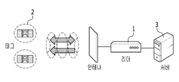
도 1은 RFID 서비스를 제공하는 환경을 나타낸 예시도이다.1 is an exemplary diagram showing an environment for providing an RFID service.
RFID 서비스를 제공하는 환경에서, 리더(1)에서 안테나를 통해 태그(2)로 RF 전력을 보내면, 전원이 없는 태그(2)는 안테나를 통하여 RF 전력을 수신하고 이러한 전파 에너지를 이용하여 동작전력을 만들어 일부 전력은 태그 내부에 전달하고 일부 전력은 반사한다. 태그(2)에서 반사하는 전력의 크기는 태그 안테나의 부하를 변화시킴으로써 조정 가능하며, 태그(2)의 안테나에서 반사되는 전력량을 조절하여 리더(1)에 데이터 정보를 전달한다. 리더(1)가 태그(2)로부터의 데이터를 수신하여 태그 ID를 인식하면 서버(3)로 태그 ID 정보를 전달하고, 서버(3)는 태그 ID를 토대로 관련된 정보를 추출하여 서비스를 제공한다.In an environment providing RFID service, if RF power is transmitted from the
본 발명의 실시 예에서는 이러한 수동형 RFID 태그의 특성을 이용하여 단말의 대기 모드에서의 소비 전력을 감소시킨다. In the embodiment of the present invention, the power consumption in the idle mode of the terminal is reduced using the characteristics of the passive RFID tag.
도 2는 본 발명의 실시 예에 따른 전원 공급 제어 태그의 구조를 나타낸 도이다. 2 is a diagram illustrating a structure of a power supply control tag according to an embodiment of the present invention.
본 발명의 실시 예에 따른 단말의 전원 공급 제어 태그(100)는 아날로그 신호 처리부(110), 디지털 신호 처리부(120), 스위칭부(130), 보안 처리부(140), 그리고 메모리부(150)를 포함한다. The power
아날로그 신호 처리부(110)는 안테나를 통하여 수신되는 신호를 입력받아 복조하며, 동작 전력을 생성하여 각 부(120, 130, 140, 150)로 공급한다. The analog
이를 위하여, 아날로그 신호 처리부(110)는 안테나를 통하여 수신되는 신호를 입력받는 매칭기(111), 전압 증배기(112), 전압 조정기(113), 복조기(114), 그리고 변조기(115)를 포함한다. The analog
매칭기(111)는 안테나로부터 수신한 신호 즉, RF(radio frequency) 신호의 전력을 직류(DC: direct current) 전압으로 변환하여 출력할 수 있다. The matching
전압 증배기(112)는 매칭기(111)로부터 출력되는 신호를 토대로 전력을 생성하며, 전압 조정기(113)는 생성된 전력을 조절하여 적정 전압을 가지는 동작 전력을 공급한다. The
복조기(114)는 매칭기(111)로부터 출력되는 신호를 복조하여 데이터(명령어 등)를 획득하고, 획득한 데이터를 디지털 신호 처리부(120)로 전달한다. The
변조기(115)는 디지털 신호 처리부(120)로부터 전달되는 데이터를 변조한다. 변조된 데이터는 안테나를 통하여 송신된다. The
한편, 디지털 신호 처리부(120)는 아날로그 신호 처리부(110)로부터 생성되는 동작 전력에 따라 동작하며, 수신된 데이터에 대응하는 동작을 수행하고 수행된 동작에 따른 정보를 아날로그 신호 처리부(110)로 전달하여 송신되도록 한다. The digital
이러한 디지털 신호 처리부(120)는 데이터 해독기(121), 실행 엔진기(122), 회신 제어기(123)를 포함한다. The digital
데이터 해독기(121)는 아날로그 신호 처리부(110)의 복조기(114)로부터 제공되는 데이터를 해독한다. 데이터 해독기(121)는 데이터를 해독하여 리더로부터 수신되는 명령어 등을 획득하여 실행 엔진기(122)로 전달한다.The
실행 엔진기(122)는 데이터 해독기(121)로부터 전달되는 해독된 데이터(예를 들어, 명령어)에 해당하는 동작을 수행한다. The
회신 제어기(123)은 실행 엔진기(122)의 동작 수행에 따른 실행 정보를 송신한다. 이를 위하여, 회신 제어기(123)는 실행 정보를 아날로그 신호 처리부(121)의 변조기(115)로 전달한다. The
한편, 보안 처리부(130)는 인증 및 보안 기능을 수행한다. Meanwhile, the
본 발명의 실시 예에 따른 전원 공급 제어 태그(100)는 일반적인 수동형 태그로 동작하는 일반 모드 그리고 보안기능을 수행하는 보안 모드의 2가지 형태로 동작한다. The power
전원 공급 제어 태그(100)가 일반적인 수동형 태그로 동작하는 일반 모드의 경우, 리더로부터의 RF 전력에 따른 전파 에너지를 이용하여 동작 전력이 만들어진 직후 또는 이후의 수동형 RFID 태그 동작 절차 도중에, 제어 신호를 발생시켜서 스위치 기능을 수행할 수 있다.In the normal mode in which the power
전원 공급 제어 태그(100)가 보안 모드로 동작하는 경우, 보안 처리부(130)는 암호화를 수행하는 보안 엔진기(131), 암호화의 동작 제어를 수행하는 보안용 로직 제어기(132)를 포함한다. When the power
보안 엔진기(131)는 보안 모드 동작시 암호화 알고리즘을 수행한다. 구체적으로, 보안 엔진기(131)는 태그와 리더간에 정해진 보안 알고리즘을 수행하여 보안 인증 기능을 수행한다. 인증이 되었을 경우 보안 인증 후 제어 신호를 생성하여 스위칭부(140)로 전달한다. 보안 엔진기(131)는 리더로부터 수신되는 데이터가 암호화되어 있는 경우, 이를 복호하여 인증을 수행할 수 있다. 예를 들어 리더의 식별자에 대한 인증을 수행할 수 있다. 여기서 암호화 알고리즘은 AES128과 같은 암호화 알고리즘일 수 있다.
보안용 로직 제어기(132)는 실행 엔진기(122)로부터 전달되는 데이터를 토대로 보안 엔진기(131)를 동작시키며 복호화 및 인증 처리가 이루어지도록 할 수 있다. The
보안 모드 동작시, 보안 엔진기(131)는 암호화 알고리즘을 수행한다. 구체적으로, 보안 엔진기(131)는 태그와 리더간에 정해진 보안 알고리즘을 수행하여 보안 인증 기능을 수행한다. 인증이 되었을 경우 보안 인증 후 제어 신호를 생성하여 스위칭부(140)로 전달한다. 이 경우, 제어 신호는 실행 엔진기(122)를 통하여 스위칭부(140)로 전달될 수 있다. In secure mode operation, the
한편, 보안 모드 동작을 위하여 AES128과 같이 별도의 암호화 모듈을 설계하지 않고, 일반적인 수동형 RFID 태그의 동작 절차를 따르는 경우에도 보안모드 동작이 가능하다. 이 경우, 보안 엔진기(131)는 일반적인 수동형 RFID 태그의 동작 절차 중 별도의 명령어가 요구되는 암호절차를 수행하고 태그의 암호 인증을 완료한 이후에 보안 모드 제어 신호를 발생시켜서 스위치 기능을 수행할 수 있다. 이 경우, 제어 신호는 실행 엔진기(122)를 통하여 스위칭부(140)로 전달될 수 있다.Meanwhile, a security mode operation can be performed even if a general passive RFID tag operation procedure is followed without designing a separate encryption module such as AES 128 for security mode operation. In this case, the
메모리부(140)는 실행 엔진기(122)에서 필요로 하는 데이터를 저장하는 실행메모리(141)와, 보안 관련 정보를 포함하는 보안용 메모리(142), 메모리로의 접근을 제어하는 메모리 제어기(143)를 포함한다. 한편, 스위칭부(150)는 전원 공급 제어 태그(100)가 적용되는 장치 예를 들어, 단말(200)로 전원을 공급한다. 특히, 단말(200)의 대기 모드에서의 전력 제어를 수행한다. The memory unit 140 includes an
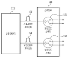
도 3은 본 발명의 실시 예에 따른 스위칭부의 구조를 나타낸 도이다. 3 is a diagram illustrating a structure of a switching unit according to an embodiment of the present invention.
첨부한 도 3에서와 같이, 스위칭부(150)는 일반 모드 스위치(151)와 보안 모드 스위치(152)를 포함한다. As shown in FIG. 3, the
일반 모드 스위치(151)는 전원 공급 제어 태그(100)가 일반적인 수동형 태그로 동작하면서 리더로부터 송신되는 신호를 수신하여 감지한 경우에, 실행 엔진기(122)로부터 전달되는 신호검색 제어신호(S1)에 따라 동작하는 스위치이다. When the power
보안 모드 스위치(152)는 전원 공급 제어 태그(100)가 보안 모드로 동작하는 경우에, 실행 엔진기(122)로부터 전달되는 보안 인증후 제어 신호(S2)에 따라 동작하는 스위치이다. 보안 모드로 동작하는 경우에, 전원 공급 제어 태그(100)는 일반적인 리더로부터 송신되는 신호를 감지하여 동작하는 것이 아니라, 태그와 리더간에 정해진 보안 알고리즘을 수행하여 보안인증 기능을 수행한 후 인증이 되었을 경우 보안 인증 후 제어 신호를 출력한다. The
각 스위치들 즉, 일반 모드 스위치(151)와 보안 모드 스위치(152)는 해당하는 제어 신호가 하이 레벨인 경우 예를 들어, 오프(Off) 상태에서 온 (On) 상태로 변환될 수 있으며, 온 상태에서 다시 오프 상태로 변환될 수 있다. For example, when the corresponding control signal is at a high level, each of the switches, that is, the
이와 같이, 스위칭부(150)의 스위칭 기능은 전원 공급 제어 태그(100)의 동작모드 설정을 통하여 결정된다. 위에서와 같이, 실행 엔진기(122)에서 설정된 동작 모드에 따라 스위칭부(150)의 동작을 위한 제어신호를 발생시킬 수 있다. 이와는 달리, 스위칭부(150)가 하나의 스위치를 포함하는 형태로 구현이 가능하게 되는데, 이 경우 실행 엔진기(122)에서 일반 모드와 보안 모드를 결정하는 것에 따라, 해당 스위치가 온 또는 오프 되면서 일반 모드 동작 신호나 보안 모드 동작 신호가 출력될 수 있다. In this way, the switching function of the
위에 기술된 바와 같은 구조로 이루어지는 전원 공급 제어 태그(100)는 단말(200)에 적용되어 단말(200)의 소비 전력을 제어할 수 있다. The power
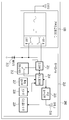
도 4는 본 발명의 실시 예에 따른 전원 공급 제어 태그를 포함한 단말의 구조를 나타낸 도이다.4 is a diagram illustrating a structure of a terminal including a power supply control tag according to an embodiment of the present invention.
단말(200)은 도 4에서와 같이, 전원 공급 제어 태그(100)와 무선 통신부(210)를 포함할 수 있다. The terminal 200 may include a power
전원 공급 제어 태그(100)는 단말의 전력 제어를 수행하며, 전력 제어 스위치용 수동형 RFID 태그 칩으로 구현될 수 있다. 전원 공급 제어 태그(100)에 대해서는 동작을 위한 배터리 전력이 요구되지 않으므로 RF 소자를 사용하는 방식과 달리 단말의 대기 전력을 소모하지 않는다. The power
무선 통신부(210)는 외부 장치와의 신호 송수신을 수행한다. 그리고 전원 공급 제어 태그(100)의 스위칭 기능을 이용하여 신호 송수신을 위한 각 부로 동작 신호를 제공한다. The
무선 통신부(210)는 도 4에서와 같이, 전원부(211), 전원 스위치(212), 배터리(213), 통신 제어부(214), 무선 송수신부(215), 안테나(216)를 포함한다. 이외에도, 무선 통신부(210)는 키 입력부(217), 디스플레이부(218)를 포함하며, 또한 센서부(219)를 더 포함할 수 있다.4, the
전원부(211)는 전원 스위치(212)를 통하여 공급되는 전원을 통신 제어부(214)로 공급한다. 통신 제어부(214)를 통하여 전원이 단말(200)의 무선 통신부(210)의 각 부로 전달될 수 있으나, 본 발명은 이것에 한정되지 않는다.The
통신 제어부(214)는 전원 공급 제어 태그(100)로부터 제공되는 신호에 따라 전원 스위치(212)를 동작시키며, 전원 스위치(212)는 무선 통신부(200)의 대기 모드에서의 소비 전력을 최소화하기 위하여 배터리(213)로부터의 전원을 전원부(211)로 공급하거나 차단한다. The
통신 제어부(214)는 전원부(211)를 통하여 전원 공급 제어 태그(100)로부터 제공되는 신호를 입력받을 수 있으나, 이에 한정되지는 않는다. The
통신 제어부(214)는 전원 공급 제어 태그(100)로부터 일반 모드 동작 신호나보안 모드 동작 신호가 출력되면 전원 스위치(212)를 동작시킨다. 즉, 전원 스위치(212)를 온(On)시키고, 무선 송수신부(215)를 통해 정해진 동작을 완료 후에는 전원 스위치(212)를 오프(Off) 시킨다. The
이러한 구조로 이루어지는 단말(200)은 대기 모드로 동작할 수 있으며, 대기 모드에서 미리 설정된 웨이크업 조건에 따라 웨이크업 모드로 동작할 수 있다. 미리 설정된 웨이크업 조건이 전원 공급 제어 태그(100)가 일반 모드로 동작하는 경우이면, 통신 제어부(214)는 대기 모드에서 전원 공급 제어 태그(100)로부터 일반 모드 동작 신호가 출력되면 전원 스위치(212)를 동작시켜 단말(200)을 웨이크업 모드로 동작시킨다. 또한 미리 설정된 웨이크업 조건이 전원 공급 제어 태그(100)가 보안 모드로 동작하는 경우이면, 통신 제어부(214)는 대기 모드에서 전원 공급 제어 태그(100)로부터 보안 모드 동작 신호가 출력되면 전원 스위치(212)를 동작시켜 단말(200)을 웨이크업 모드로 동작시킨다.The terminal 200 having such a structure can operate in the standby mode, and can operate in the wakeup mode in accordance with the wake-up condition preset in the standby mode. When the power
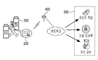
도 5는 본 발명의 실시 예에 따른 전원 공급 제어 태그를 구비한 단말에 대한 서비스가 제공되는 경우를 나타낸 예시도이다. 도 6은 본 발명의 실시 예에 따른 전원 공급 제어 방법의 흐름도이다.5 is a diagram illustrating a case where a service for a terminal equipped with a power supply control tag according to an embodiment of the present invention is provided. 6 is a flowchart of a power supply control method according to an embodiment of the present invention.
본 발명의 실시 예에 따른 단말(200)이 전원 공급 제어 태그(100)를 포함하는 형태로 구현되고, 도 5와 같은 환경에서 서비스를 받는 것을 가정하여 설명한다. 도 5와 같은 환경에서 태그를 인식하기 위한 리더로 기능하는 웨이크업(wake-up) 판독기(300)와, 통신망 연결을 위한 무선 AP(access point)가 설치되어 있다. 예를 들어, 웨이크업 판독기(300)는 출입구에 설치되어 전력제어용 태그칩인 전원 공급 제어 태그(100)와 근거리 통신을 통해 태그의 정보를 판독하는 기능을 수행할 수 있다. 이를 위하여, 웨이크업 판독기(300)는 태그를 동작시키기 위한 신호를 송신한다. It is assumed that the terminal 200 according to the embodiment of the present invention is implemented in a form including the power
단말(200)이 도 5와 같은 서비스 환경에 진입하게 되면, 단말(200)의 전원 공급 제어 태그(100)는 도 6에서와 같이, 웨이크업 판독기(300)로부터 송신되는 신호 즉, 태그 동작 신호를 수신한다. 단말(200)이 대기 모드로 동작하고 있는 상태에서, 전원 공급 제어 태그(100)는 웨이크업 판독기(300)로부터 태그 동작 신호를 수신한다(S100, S110). 5, the power
단말(200)이 대기 모드로 동작하고 있는 상태에서는 전원 공급 제어 태그(100)로부터 전원 공급을 위한 신호(일반 모드 동작 신호나 보안 모드 동작 신호)가 단말(200)의 무선 통신부(210)로 공급되고 있지 않은 상태이다. 즉, 전원 공급 제어 태그(100)의 스위칭부(150)의 일반 모드 스위치(151)와 보안 모드 스위치(152)가 모두 오프된 상태이므로 일반 모드 동작 신호나 보안 모드 동작 신호가 무선 통신부(210)로 공급되지 않는다. 이 경우, 무선 통신부(210)의 통신 제어부(214)는 단말(200)이 별도의 동작을 수행하지 않는 경우에는 전원 스위치(212)를 오프시켜 배터리(213)로부터의 전원이 전원부(211)로 공급되지 않는다. 그 결과, 대기 모드에서는 단말(200)의 무선 통신부(210)로의 전원 공급이 차단되어, 대기 모드에서의 소비 전력이 감소될 수 있다. (Normal mode operation signal or security mode operation signal) from the power
이러한 대기 모드 상태에서, 전원 공급 제어 태그(100)가 웨이크업 판독기(300)로부터 송신되는 태그 동작 신호를 수신하면(S100), 전원 공급 제어 태그(100)는 일반 모드나 보안 모드로 동작한다. In this standby mode, when the power
전원 공급 제어 태그(100)는 태그 동작 신호를 수신하여 처리하고, 일반 모드 또는 보안 모드를 결정한다. 예를 들어, 수신된 태그 동작 신호가 일반적인 리더(예를 들어, 수동형 RFID 리더)에서 송신하는 신호인 경우에는, 일반 모드로 동작한다. 이 경우, 전원 공급 제어 태그(100)는 리더로부터의 RF 전력에 따른 전파 에너지를 이용하여 동작 전력이 만들어진 직후 또는 수동형 RFID 태그 동작 절차 도중에, 스위칭부(150)의 일반 모드 스위치(151)를 동작시킨다. 일반 모드 스위치(151)가 동작 즉, 온 상태가 됨에 따라 일반 모드 동작 신호가 무선 통신부(210)로 출력된다(S120, S130). The power
또한, 전원 공급 제어 태그(100)는 보안 모드로 동작하는데, 예를 들어, 태그 동작 신호가 일반적인 리더가 송신하는 신호가 아니고 서비스 제공 등에 관련된 신호인 경우, 보안 모드로 동작한다. 이 경우, 전원 공급 제어 태그(100)는 보안 인증을 수행한 인증 결과에 따라 단말을 동작시킨다. In addition, the power
구체적으로, 전원 공급 제어 태그(100)의 보안 처리부(130)는 태그 동작 신호가 일반적인 리더가 송신하는 신호가 아니고 서비스 제공 등에 관련된 신호인 경우, 태그 동작 신호를 송신한 해당 리더 즉, 웨이크업 판독기(300)로 인증을 위한 정보를 요청하고 이에 따라 수신되는 정보를 토대로 웨이크업 판독기(300)에 의한 인증이 이루어지면, 실행 엔진기(122)로 인증 결과를 통보한다. 실행 엔진기(122)는 웨이크업 판독기(300)에 대한 인증이 이루어진 경우에 스위칭부(150)의 보안 모드 스위치(152)를 동작시킨다. 이에 따라 보안모드 스위치(152)가 동작 즉, 온 상태가 됨에 따라 보안 모드 동작 신호가 무선 통신부(210)로 출력된다(S140). 이때, 보안 모드 동작에서 전원 공급 제어 태그(100)의 일반모드 스위치 제어신호와 보안모드 스위치 제어신호가 모두 ON 상태가 되는데, 일반모드 스위치 제어신호가 먼저 ON 상태가 되고 보안모드 제어 신호가 나중에 ON 상태가 될 수 있다. Specifically, when the tag operation signal is not a signal transmitted by a general reader but a signal related to service provision or the like, the
단말(200)의 무선 통신부(210)의 통신 제어부(214)는 대기 모드 상태에서 전원 공급 제어 태그(100)의 동작 모드에 따라 출력되는 신호를 토대로 선택적으로 웨이크업 된다. The
미리 설정된 웨이크업 조건이 전원 공급 제어 태그(100)가 일반 모드로 동작하는 경우, 전원 공급 제어 태그(100)의 일반모드 스위치(151)가 동작되면서 일반 모드 동작 신호가 무선 통신부(210)로 수신되면 즉, 전원 공급 제어 태그(100)가 일반 모드로 동작하면(S150, S160), 단말(200)은 대기 모드에서 웨이크업 모드로 동작한다. 구체적으로 단말(200)의 통신 제어부(214)는 전원 스위치(212)를 동작시켜 단말(200)을 웨이크업시킨다(S170). 이때, 전원 공급 제어 태그(100)로부터 일반모드 동작 신호가 전달되지 않는 경우에는 단말(200)이 대기 모드 상태를 유지한다(S180). When the power
한편, 단계(S150)에서, 미리 설정된 웨이크업 조건이 전원 공급 제어 태그(100)가 보안 모드로 동작하는 경우, 전원 공급 제어 태그(100)의 보안모드 스위치(151)가 동작되면서 보안 모드 동작 신호가 무선 통신부(210)로 수신되면, 즉, 전원 공급 제어 태그(100)가 보안 모드로 동작하면(S190), 단말(200)은 대기 모드에서 웨이크업 모드로 동작한다. 이때, 단말(200)은 태그 동작 신호에 따라 일반모드 스위치(151)가 온 되어 일반 모드 동작 신호가 전달되어도 전원 스위치(212)를 동작시키지 않고 대기 모드를 유지한다(S180). 그리고 일반 모드 동작 신호가 전달된 다음에 보안 모드 동작 신호가 전달되면, 전원 스위치(212)를 동작시켜 대기 모드에서 웨이크업 모드로 동작한다(S180). When the power
단말(200)이 웨이크업 모드로 동작함에 따라 전원 스위치(212)를 통하여 배터리(213)로부터의 전원이 전원부(211)를 통하여 각 부로 공급됨으로써, 단말(200)의 무선 통신부(210)가 동작하여, 외부와의 신호 송수신이 가능하게 된다. 단말(200)은 예를 들어 도 5와 같은 서비스 환경에서 웨이크업되면, 무선 AP(400)를 통하여 서버(400)로부터 제공되는 다양한 서비스를 제공받을 수 있다. The power from the
위의 동작에 있어서 단말(200)에 있는 전원스위치(212)를 전원 공급 제어 태그(100)에 포함시키는 구성도 가능하다. 그리고 웨이크업 조건은 단말(200)이나 전원 공급 제어 태그(100) 제조시에 설정되거나 또는 별도의 선택 과정(예를 들어, 스위치를 통한 조건 설정이나 별도의 프로그램(앱 등)을 통한 조건 설정 등)을 통하여 설정될 수 있다. It is also possible to include the
이와 같이, 단말(200)은 전력 소비를 최소화하기 위하여 동작을 하지 않을 경우에는 대다수 기능모듈에 전원공급을 차단하는 대기 모드로 있다가 동작을 해야 하는 시점에 웨이크업 되어 동작을 시작한다. 또한, 단말이 대기 모드에서도 웨이크업을 위한 신호 검출을 수행하지 않고 전원 공급 제어 태그로부터 인가되는 신호에 따라 웨이크업됨으로써, 단말의 전력 소비가 거의 없다. 결과적으로 1uA의 대기전력을 1nA 수준으로 낮추게 되므로 대기모드에서 약 1/100정도로 소비전력을 줄일 수 있다. In this way, when the terminal 200 does not operate in order to minimize power consumption, the terminal 200 is in a standby mode for interrupting power supply to a plurality of function modules, and wakes up at the time when the terminal 200 is to be operated. Further, the terminal does not perform signal detection for wake-up even in the standby mode, and is woken up according to a signal applied from the power supply control tag, so that power consumption of the terminal is hardly obtained. As a result, the standby power of 1uA is reduced to 1nA, which reduces power consumption by about 1/100 in standby mode.
또한, 임의의 무선 AP에 의하여 서비스를 원하지 않거나 제공하지 않는 장소에서도 무선 AP로부터 전달되는 신호를 웨이크업 신호로 인식하여 단말이 동작할 수 있는데, 본 발명의 실시 예에 따르면, 전원 공급 제어 태그를 통한 보안 인증이 이루어진 경우에 단말로 전원이 공급됨으로써, 단말의 불필요한 웨이크업 동작에 따른 전력 소모를 방지할 수 있다. 또한, 신호를 송신한 대상에 대한 보안 인증 후 단말이 대기 모드에서 웨이크업 됨으로써, 보안성을 향상시킬 수 있다. Also, the terminal may operate by recognizing a signal transmitted from the wireless AP as a wake up signal even in a place where a service is not desired or provided by a certain wireless AP. According to an embodiment of the present invention, Power is supplied to the terminal when security authentication is performed through the terminal, thereby preventing power consumption due to an unnecessary wakeup operation of the terminal. Further, the security can be improved by waking up the terminal in the standby mode after the security authentication for the object to which the signal is transmitted.
본 발명의 실시 예는 이상에서 설명한 장치 및/또는 방법을 통해서만 구현이 되는 것은 아니며, 본 발명의 실시예의 구성에 대응하는 기능을 실현하기 위한 프로그램, 그 프로그램이 기록된 기록 매체 등을 통해 구현될 수도 있으며, 이러한 구현은 앞서 설명한 실시예의 기재로부터 본 발명이 속하는 기술분야의 전문가라면 쉽게 구현할 수 있는 것이다.The embodiments of the present invention are not limited to the above-described apparatuses and / or methods, but may be implemented through a program for realizing functions corresponding to the configuration of the embodiment of the present invention, a recording medium on which the program is recorded And such an embodiment can be easily implemented by those skilled in the art from the description of the embodiments described above.
이상에서 본 발명의 실시 예에 대하여 상세하게 설명하였지만 본 발명의 권리범위는 이에 한정되는 것은 아니고 다음의 청구범위에서 정의하고 있는 본 발명의 기본 개념을 이용한 당업자의 여러 변형 및 개량 형태 또한 본 발명의 권리범위에 속하는 것이다.While the present invention has been particularly shown and described with reference to exemplary embodiments thereof, it is to be understood that the invention is not limited to the disclosed exemplary embodiments, It belongs to the scope of right.
Claims (15)
단말에 전원 공급 제어 태그가 포함되어 있는 상태에서, 상기 전원 공급 제어 태그가 태그 동작 신호를 수신하여 일반 모드 또는 보안 모드로 동작되는 단계;
미리 설정된 웨이크업(wake-up) 조건이 보안 모드인 경우, 상기 전원 공급 제어 태그가 보안 모드로 동작되면, 상기 단말이 대기 모드에서 웨이크업 모드로 동작되는 단계; 및
미리 설정된 웨이크업 조건이 일반 모드인 경우, 상기 전원 공급 제어 태그가 일반 모드로 동작되면, 상기 단말이 대기 모드에서 웨이크업 모드로 동작되는 단계;
를 포함하는, 전원 공급 제어 방법.In a method of controlling power supply of a terminal in a standby mode,
The power supply control tag receiving a tag operation signal and operating in a normal mode or a security mode in a state where a power supply control tag is included in the terminal;
If the predetermined wake-up condition is a security mode, operating the terminal in a wake-up mode from a standby mode if the power-supply control tag is operated in a secure mode; And
When the predetermined wakeup condition is the normal mode, operating the wakeup mode when the power supply control tag operates in the normal mode;
/ RTI >
상기 전원 공급 제어 태그가 일반 모드 또는 보안 모드로 동작되는 단계는,
상기 태그 동작 신호가 서비스 제공에 관련된 신호인 경우, 상기 전원 공급제어 태그가 보안 모드로 동작하는 단계; 및
상기 태그 동작 신호가 서비스 제공에 관련된 신호가 아닌 경우, 상기 전원 공급제어 태그가 일반 모드로 동작하는 단계
를 포함하는, 전원 공급 제어 방법.The method of claim 1, wherein
Wherein the power supply control tag is operated in a normal mode or a secure mode,
Operating the power supply control tag in a secure mode when the tag operation signal is a signal related to service provision; And
When the tag operation signal is not a signal related to service provision, the power supply control tag operates in a normal mode
/ RTI >
상기 일반 모드로 동작하는 단계는,
상기 태그 동작 신호에 따른 전파 에너지를 이용하여 동작 전력이 만들어진 직 후 또는 상기 전원 공급 제어 태그가 수동형 RFID(radio frequency identification) 태그로서 동작하는 도중에, 상기 전원 공급 제어 태그가 일반 모드로 동작하는 신호를 상기 단말로 전달하는 단계
를 포함하는 전원 공급 제어 방법.The method according to claim 2, wherein
Wherein the operating in the normal mode comprises:
The power supply control tag may operate in the normal mode immediately after the operation power is generated using the radio wave energy according to the tag operation signal or during operation of the power supply control tag as a passive RFID tag To the terminal
Lt; / RTI >
상기 보안 모드로 동작하는 단계는
상기 일반 모드로 동작하는 신호를 상기 단말로 전달한 다음에, 상기 태그 동작 신호를 송신한 대상에 대한 인증이 이루어진 경우에, 상기 전원 공급 제어 태그가 보안 모드로 동작하는 신호를 상기 단말로 전달하는 단계
를 포함하는, 전원 공급 제어 방법.The method of claim 3, wherein
The step of operating in the secure mode
Transmitting a signal operating in the normal mode to the terminal and transmitting a signal for operating the security mode of the power supply control tag to the terminal when authentication is performed for an object to which the tag operation signal is transmitted
/ RTI >
리더로부터 송신되는 태그 동작 신호를 수신하고 인가되는 회신 데이터를 송신하는 아날로그 신호 처리부;
상기 태그 동작 신호를 복조하여 데이터를 획득하고, 획득된 데이터에 대한 회신 데이터를 상기 아날로그 신호 처리부로 전달하는 디지털 신호 처리부;
상기 디지털 신호 처리부로부터 전달되는 데이터를 토대로 상기 리더에 대한 인증을 수행하는 보안 처리부; 및
상기 디지털 신호 처리부로부터 전달되는 데이터 및 상기 보안 처리부의 인증 수행 여부에 따라 상기 단말로 전원 공급 제어 태그 동작에 따른 신호를 전달하는 스위칭부
를 포함하는, 전원 공급 제어 태그.In a power supply control tag for controlling the power supply of the terminal,
An analog signal processing unit for receiving the tag operation signal transmitted from the reader and transmitting the received response data;
A digital signal processing unit for demodulating the tag operation signal to acquire data, and delivering return data for the obtained data to the analog signal processing unit;
A security processing unit for performing authentication on the reader based on data transmitted from the digital signal processing unit; And
A switching unit for transmitting a signal according to a power supply control tag operation to the terminal according to data transmitted from the digital signal processing unit and whether or not the security processing unit performs authentication,
And a power supply control tag.
상기 스위칭부는
상기 보안 처리부에 의하여 인증이 수행된 경우에 동작하여 보안 모드 동작 신호를 출력하는 보안 모드 스위치; 및
상기 태그 동작 신호가 수신되었지만 인증이 수행되지 않은 경우에 동작하여 일반 모드 동작 신호를 출력하는 일반 모드 스위치
를 포함하는, 전원 공급 제어 태그The method of claim 5, wherein
The switching unit
A security mode switch that operates when the authentication is performed by the security processing unit and outputs a security mode operation signal; And
A normal mode switch that operates when the tag operation signal is received but authentication is not performed and outputs a normal mode operation signal;
A power supply control tag
상기 태그 동작 신호에 따른 전파 에너지를 이용하여 동작 전력이 만들어진 직 후 또는 상기 전원 공급 제어 태그가 수동형 RFID(radio frequency identification) 태그로서 동작하는 도중에, 상기 일반 모드 스위치가 동작되어 일반 모드 동작 신호가 출력된 다음에, 상기 보안 처리부에 의한 인증이 수행된 경우 상기 보안 모드 스위치가 동작되어 보안 모드 동작 신호가 출력되는, 전원 공급 제어 태그.The method of claim 6, wherein
Immediately after the operation power is generated by using the radio wave energy according to the tag operation signal, or while the power supply control tag operates as a passive RFID (radio frequency identification) tag, the normal mode switch is operated, The security mode switch is operated to output a security mode operation signal when authentication by the security processing unit is performed.
상기 보안 처리부의 인증을 위한 보안용 데이터를 포함하는 메모리부
를 더 포함하는, 전원 공급 제어 태그The method of claim 5, wherein
A memory unit including security data for authentication of the security processing unit,
Further comprising a power supply control tag
상기 보안 처리부는
상기 아날로그 신호 처리부와 연계하여 상기 리더와 인증을 위한 데이터를 암호화하여 송수신하는 보안 엔진기; 및
상기 보안 엔진기의 암호화의 동작 제어를 수행하고, 인증 결과를 상기 디지털 신호 처리부로 전달하는 보안용 로직 제어기
를 포함하는, 전원 공급 제어 태그The method of claim 5, wherein
The security processing unit
A security engine for encrypting and transmitting data for authentication with the reader in cooperation with the analog signal processor; And
A security logic controller for performing an operation control of encryption of the security engine and transmitting an authentication result to the digital signal processor;
A power supply control tag
대기 모드 상태에서 상기 전원 공급 제어 태그의 동작 모드에 따라 웨이크업(wake-up) 모드로 동작하는 무선 통신부
를 포함하는, 단말.A power supply control tag which receives a tag operation signal transmitted from a reader and operates in accordance with the tag operation signal; And
A wireless communication unit operating in a wake-up mode according to an operation mode of the power supply control tag in a standby mode,
.
상기 전원 공급 제어 태그가 상기 리더에 대한 인증을 수행하면 보안 모드 동작 신호를 출력하고, 상기 인증을 수행하지 않은 경우에는 일반 모드 동작 신호를 출력하는 스위칭부
를 더 포함하는, 단말.The method of claim 10, wherein
And outputs a security mode operation signal when the power supply control tag performs authentication with respect to the reader and outputs a normal mode operation signal when the authentication is not performed,
Further comprising:
상기 무선 통신부는 미리 설정된 웨이크업 조건이 일반 모드인 경우, 상기 스위칭부로부터 일반 모드 동작 신호가 출력되면 웨이크업 모드로 동작하고, 미리 설정된 웨이크업 조건이 보안 모드인 경우, 상기 스위칭부로부터 보안 모드 동작 신호가 출력되면 웨이크업 모드로 동작하는, 단말.The method of claim 11, wherein
Wherein the wireless communication unit operates in a wakeup mode when a pre-set wakeup condition is a normal mode and a normal mode operation signal is output from the switching unit, and when the wakeup condition is a security mode, And operates in a wakeup mode when an operation signal is output.
상기 무선 통신부는
배터리에 연결되는 전원 스위치; 및
상기 스위칭부로부터 전달되는 신호에 따라 상기 전원 스위치를 동작시켜 단말을 웨이크업 모드로 동작시키는 통신 제어부
를 포함하는 단말.The method of claim 12, wherein
The wireless communication unit
A power switch connected to the battery; And
And a communication controller for operating the terminal in a wakeup mode by operating the power switch according to a signal transmitted from the switching unit,
.
상기 스위칭부는 상기 태그 동작 신호에 따른 전파 에너지를 이용하여 상기전원 공급 제어 태그의 동작 전력이 만들어진 직후 또는 상기 전원 공급 제어 태그가 수동형 RFID(radio frequency identification) 태그로서 동작하는 도중에, 일반 모드 동작 신호를 출력한 다음에, 상기 보안 처리부에 의한 인증이 수행된 경우에 보안 모드 동작 신호를 출력하는, 단말.The method of claim 12, wherein
The switching unit may be configured to generate the normal mode operation signal immediately after the operation power of the power supply control tag is generated using the radio wave energy according to the tag operation signal or while the power supply control tag operates as a passive RFID And outputs a security mode operation signal when authentication by the security processing unit is performed.
상기 무선 통신부는 미리 설정된 웨이크업 조건이 보안 모드인 경우, 상기 스위칭부로부터 일반 모드 동작 신호가 출력된 다음에 보안 모드 동작 신호가 출력되면 웨이크업 모드로 동작하는, 단말.The method of claim 14, wherein
Wherein the wireless communication unit operates in a wakeup mode when a security mode operation signal is output after a normal mode operation signal is output from the switching unit when a predetermined wakeup condition is a security mode.
Priority Applications (1)
| Application Number | Priority Date | Filing Date | Title |
|---|---|---|---|
| KR1020150109732A KR20170016247A (en) | 2015-08-03 | 2015-08-03 | Tag for power supply control and method for controlling power supply in sleep mode by using the tag |
Applications Claiming Priority (1)
| Application Number | Priority Date | Filing Date | Title |
|---|---|---|---|
| KR1020150109732A KR20170016247A (en) | 2015-08-03 | 2015-08-03 | Tag for power supply control and method for controlling power supply in sleep mode by using the tag |
Publications (1)
| Publication Number | Publication Date |
|---|---|
| KR20170016247A true KR20170016247A (en) | 2017-02-13 |
Family
ID=58156125
Family Applications (1)
| Application Number | Title | Priority Date | Filing Date |
|---|---|---|---|
| KR1020150109732A KR20170016247A (en) | 2015-08-03 | 2015-08-03 | Tag for power supply control and method for controlling power supply in sleep mode by using the tag |
Country Status (1)
| Country | Link |
|---|---|
| KR (1) | KR20170016247A (en) |
-
2015
- 2015-08-03 KR KR1020150109732A patent/KR20170016247A/en unknown
Similar Documents
| Publication | Publication Date | Title |
|---|---|---|
| JP4500123B2 (en) | Wireless communication method, base station, wireless terminal device, and wireless communication system | |
| US20090224890A1 (en) | Active rfid tag | |
| KR101602655B1 (en) | Radio frequency SIM card, radio frequency card reader, and magnetic induction control method for radio frequency communication | |
| KR20080052949A (en) | Power cut-off apparatus and method in radio frequency identification systems | |
| JP2008129988A (en) | Information access system, reader/writer, and active type non-contact information storage device | |
| EP3451543A1 (en) | Nfc device and power management method | |
| EP2133826B1 (en) | RFID tag with improved reading range | |
| US11409970B2 (en) | UWB communication device and corresponding operating method | |
| CN110809312A (en) | Low-power-consumption NFC device, electronic equipment and working method | |
| KR102216487B1 (en) | Energy harvesting system, apparatus and method for performing wakeup | |
| JP2008011422A (en) | Information access system, active type non-contact information storage device, and method for accessing information in non-contact information storage device | |
| JP4282618B2 (en) | Active wireless tag and driving method thereof | |
| JP4866453B2 (en) | Wireless communication method, wireless terminal device, and wireless communication system | |
| KR20110064690A (en) | Apparatus and method for recognizing tag of reader in radio frequency identification | |
| KR101001681B1 (en) | Active ???? Systems and Method for controlling Tag Wake up the same | |
| JP2007067791A (en) | Information access system, and reading writing apparatus for active type noncontact information storage device | |
| KR101094474B1 (en) | Method for Control Automatic Wake-up/Sleep of Tag Type Wireless Short Device and Wireless Short Communication System therefor | |
| KR20170016247A (en) | Tag for power supply control and method for controlling power supply in sleep mode by using the tag | |
| WO2010116307A1 (en) | Rfid device being operable in a first and a second operating state | |
| JP2000049654A (en) | Rfid system | |
| JP3557342B2 (en) | Communications system | |
| JP5459297B2 (en) | Wireless receiver, wireless communication system, program | |
| JP2007065960A (en) | Information access system and active-type noncontact information memory device | |
| JP4514559B2 (en) | Mobile device | |
| KR101455695B1 (en) | Method of System Wake-Up for Wireless Power Transfer Apparatus |