KR20170004802A - Waterproof connector housing - Google Patents
Waterproof connector housing Download PDFInfo
- Publication number
- KR20170004802A KR20170004802A KR1020150153846A KR20150153846A KR20170004802A KR 20170004802 A KR20170004802 A KR 20170004802A KR 1020150153846 A KR1020150153846 A KR 1020150153846A KR 20150153846 A KR20150153846 A KR 20150153846A KR 20170004802 A KR20170004802 A KR 20170004802A
- Authority
- KR
- South Korea
- Prior art keywords
- terminal
- lance
- chamber
- fitting
- retainer
- Prior art date
Links
Images


Classifications
-
- H—ELECTRICITY
- H01—ELECTRIC ELEMENTS
- H01R—ELECTRICALLY-CONDUCTIVE CONNECTIONS; STRUCTURAL ASSOCIATIONS OF A PLURALITY OF MUTUALLY-INSULATED ELECTRICAL CONNECTING ELEMENTS; COUPLING DEVICES; CURRENT COLLECTORS
- H01R13/00—Details of coupling devices of the kinds covered by groups H01R12/70 or H01R24/00 - H01R33/00
- H01R13/46—Bases; Cases
- H01R13/52—Dustproof, splashproof, drip-proof, waterproof, or flameproof cases
- H01R13/5205—Sealing means between cable and housing, e.g. grommet
-
- H—ELECTRICITY
- H01—ELECTRIC ELEMENTS
- H01R—ELECTRICALLY-CONDUCTIVE CONNECTIONS; STRUCTURAL ASSOCIATIONS OF A PLURALITY OF MUTUALLY-INSULATED ELECTRICAL CONNECTING ELEMENTS; COUPLING DEVICES; CURRENT COLLECTORS
- H01R13/00—Details of coupling devices of the kinds covered by groups H01R12/70 or H01R24/00 - H01R33/00
- H01R13/40—Securing contact members in or to a base or case; Insulating of contact members
- H01R13/42—Securing in a demountable manner
- H01R13/422—Securing in resilient one-piece base or case, e.g. by friction; One-piece base or case formed with resilient locking means
-
- H—ELECTRICITY
- H01—ELECTRIC ELEMENTS
- H01R—ELECTRICALLY-CONDUCTIVE CONNECTIONS; STRUCTURAL ASSOCIATIONS OF A PLURALITY OF MUTUALLY-INSULATED ELECTRICAL CONNECTING ELEMENTS; COUPLING DEVICES; CURRENT COLLECTORS
- H01R13/00—Details of coupling devices of the kinds covered by groups H01R12/70 or H01R24/00 - H01R33/00
- H01R13/648—Protective earth or shield arrangements on coupling devices, e.g. anti-static shielding
- H01R13/658—High frequency shielding arrangements, e.g. against EMI [Electro-Magnetic Interference] or EMP [Electro-Magnetic Pulse]
- H01R13/6581—Shield structure
Abstract
[PROBLEMS] To provide a waterproof connector housing that can be surely prevented from slipping into a terminal accommodating chamber without interposing an external member even on a small terminal metal fitting.
[MEANS FOR SOLVING PROBLEMS] In a waterproof connector housing having a housing main body made of synthetic resin and a retainer, the housing main body is formed in a cantilever shape from the rear end side to the front side on the bottom wall of the square- An upper lance having a lower lance having a lower locking projection engaged with a locking hole of the bottom plate and an upper locking projection formed on the upper wall in a cantilever shape from the front end side to the rear side and engaging with the upper plate of the terminal connection portion; A lower space for receiving the displacement and an upper space for receiving the elastic displacement of the upper lance, and the retainer has a lower wedge-shaped projection projecting into the lower space and the upper space to regulate the elastic displacement of the lower lance and the upper lance, And a wedge-shaped projection.
Description
BACKGROUND OF THE INVENTION 1. Field of the Invention The present invention relates to a waterproof connector housing having, for example, a terminal accommodating chamber for accommodating female terminal fittings or male terminal fittings, and more particularly to means for preventing the terminal fittings from coming off.
BACKGROUND ART Conventionally, an automotive connector used for connecting a wire harness or the like is a waterproof type connector housing, in which a terminal metal fitting, which is connected to a rear end side, is inserted into a terminal accommodating chamber formed in a housing main body, It is general that the terminal metal fitting is prevented and fixed by being pulled in by the retainer. In general, the male and female connector housings have a front end shape in which the housing main bodies into which the retainers are inserted fit each other. When the male and female connector housings are fitted, the front ends of the terminal accommodating chambers corresponding to each other come in contact with each other, The metal fitting and the male terminal fitting are connected.
The
The
In the waterproof connector, a rubber stopper (13) is fitted on the insulating cover (12) behind the terminal core wire (10) which is normally crimped by the wire barrel (7a) of the wire (10). The
The
In addition, a cantilever-
A
When the
As described above, in the conventional waterproof connector housing, the terminal fittings are prevented from slipping out by the engagement of the locking projections of the lance formed in the bottom wall of the terminal accommodating chamber and the locking holes formed in the bottom plate of the terminal connection portion. Further, due to the integration of the present connectors and the miniaturization of the terminal metal fittings, the metal plates constituting the terminal metal fittings are also thinner, the terminal connecting portions themselves are also small in width, and are easily deformed by external pressure. Therefore, the locking force for retaining the terminal metal fittings is also weak, so that any one of the terminal fittings can be moved rearward in the terminal accommodating chamber by the pushing resistance when the male terminal tabs of the male terminal fittings are inserted into the terminal connecting portions of the female terminal fittings So that there is a fear that the electrical connection becomes poor.
The connector housing may have a structure in which a separate locking member is inserted and interposed from the outside in the middle of the terminal accommodating chamber. However, in the waterproof connector, a region for inserting a rubber stopper or a sealing member in the housing has already been formed So that an additional solution is not practical in that an additional external member intervening region is added to enlarge the overall connector. Further, by forming the insertion hole on the wall surface of the connector side, the waterproof function may be impaired.
SUMMARY OF THE INVENTION It is an object of the present invention to provide a waterproof connector housing capable of reliably preventing a small terminal metal fitting from slipping out in a terminal accommodating chamber without interposing an external member.
In order to attain the above object, a waterproof connector housing according to a first aspect of the present invention includes: a housing body made of synthetic resin having at least one terminal accommodating chamber in which a terminal metal fitting connected to a wire terminal is inserted forwardly from a rear end thereof, A waterproof connector housing having a retainer made of a synthetic resin that is fitted to the front end side of the terminal housing chamber of the housing main body from the front to prevent the terminal metal fittings from slipping out,
Wherein the terminal accommodating chamber is formed in a front region of the terminal accommodating chamber and has an angular terminal-shaped chamber in which an angular terminal connection portion of the terminal bracket provided with a contact piece for obtaining electrical connection with a terminal of the opponent terminal, And a cylindrical space for inserting a waterproof rubber stopper fitted around a wire extending from a rear end side of the female terminal metal fitting,
The hatchery chamber has a lower lance which is elastically displaceable in a vertical direction formed in a cantilever shape forward from a rear end side of the square barrel on a bottom wall, and a lower lance which is elastically displaceable in a vertical direction and which is formed in a cantilever shape rearward from the front end side of the square- And an upper lance capable of elastic displacement,
Wherein the lower lance has a lower locking projection formed in the vicinity of the free end thereof and engaged from below with a locking hole formed in the bottom plate of the terminal connection portion when the terminal connection portion of the female terminal fitting is inserted into the square-
Wherein the upper lance is formed at its free end and has an upper locking protrusion that is engaged with the upper plate of the terminal connecting portion at a position behind the lower locking protrusion when the terminal connecting portion of the female terminal fitting is inserted into the square-
The housing main body has a lower space below the lower lance for receiving elastic displacement of the lower lance and an upper space for receiving elastic displacement of the upper lance on the upper lance,
Wherein the retainer has a lower wedge-shaped projection portion which is respectively inserted into the lower space and the upper space when fitting the front end side of the terminal housing chamber of the housing body from the front to regulate the elastic displacement of the lower lance and the upper lance, And is provided with a protruding portion.
According to a second aspect of the present invention, in the waterproof connector housing for a female terminal according to the first aspect of the present invention, the hatch-shaped chamber is formed as a hollow chamber in a columnar convex portion fitted in the recess formed in the retainer,
The upper lance is configured to be partially displaced by the coaxial slit from the upper wall of the square barrel-shaped wall made up of the plate-shaped wall of the columnar convex portion to be elastically displaceable,
And the slit is sealed by engagement of the concave portion of the retainer with the columnar convex portion.
According to a third aspect of the invention, in the waterproof connector housing according to the first or second aspect, the upper lance and the upper locking protrusion are disposed at a position where a rear end surface thereof is projected in the opening face of the cylindrical loss chamber.
(Effects of the Invention)
In the waterproof connector housing for a female terminal according to the present invention, the lower locking projection of the lower lance formed on the bottom wall of the terminal accommodating chamber and the upper locking projection of the upper lance formed on the upper wall prevent slippage of the female terminal fitting at two places. Since the upper and lower lances are configured to be elastically displaceable in the vertical direction at the time of insertion of the female terminal fittings, even a small female terminal fitting formed of a thin and small-width metal can be inserted into the terminal accommodating chamber well without distortion, So that it is stably held in the terminal accommodating chamber.
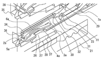
BRIEF DESCRIPTION OF DRAWINGS FIG. 1 is a longitudinal sectional view showing a schematic partial structure of a waterproof connector housing for a female terminal according to an embodiment of the present invention, and is a side sectional view in a state in which a female terminal fitting is housed.
Fig. 2 is a partial cross-sectional perspective view of the waterproof connector housing for a female terminal of Fig. 1. Fig.
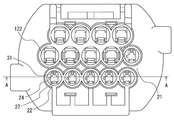
3 is a rear view showing the housing main body of the waterproof connector housing for the female terminal shown in Fig. 1 in a state in which the female terminal metal fitting is not received.
4 is a cross-sectional view of the housing body of FIG. 3 taken along line AA.
Fig. 5 is a side cross-sectional view in a state in which a male terminal fitting is housed, which shows a schematic partial structure of a waterproof connector housing for a male member, which is a counterpart of the female connector waterproof connector housing of Fig.
Fig. 6 is a partial cross-sectional perspective view of the waterproof connector housing for the implement of Fig. 5;
7 is a schematic partial cross-sectional view showing another locking bracket of the upper lance in the waterproof connector housing according to the present invention.
Fig. 8 is a vertical cross-sectional view showing an example of a conventional waterproof connector housing for female terminals. Fig. 8 (a) shows a state in which a retainer has not been inserted yet, and Fig. 8 (b) shows a state in which a retainer has been fully inserted.
A waterproof connector housing for a female terminal according to the present invention comprises a housing main body made of a synthetic resin having at least one terminal accommodating chamber and a synthetic resin member which is fitted to the front end side of the terminal housing chamber of the housing main body from the front to prevent the female terminal fittings from coming off A waterproof connector housing provided with a resin retainer is provided with an angular cylinder chamber in which an angular terminal connection portion of a terminal metal fitting provided with a contact piece for obtaining electrical connection with a terminal of a counterpart is formed in a front region of the terminal accommodating chamber, Wherein a cylindrical lid for inserting a waterproofing rubber stopper fitted around a wire extending from a rear end side of the terminal metal fitting is formed in a rear region of the square tubular body so as to extend from the rear end side of the square tubular body to the bottom wall, A lower lance which is elastically displaceable in a vertical direction and which is formed in a cantilever shape toward the upper wall, In the up-and-down direction is formed in a cantilever-like toward the rear from the front end side of the square tube-type lost is provided with a top lance is elastically displaced. Further, in the waterproof connector housing of the present invention, the insertion (advancing) direction of the terminal fitting is forward and the electric wire side is rearward.
The lower lance has a lower locking projection formed in the vicinity of its free end and engaged with a locking hole formed in the bottom plate of the terminal connection portion from the lower side when the terminal connection portion of the terminal fitting is inserted into the square- And the housing main body has an upper locking protrusion which is formed at the free end thereof and engages with the upper plate of the terminal connecting portion when the terminal connection portion of the terminal fitting is inserted into the square barrel, A lower space is formed in the lower lance and an upper space for receiving elastic displacement of the upper lance is formed on the upper lance. When the retainer is fitted to the front end side of the terminal accommodating chamber of the housing main body from the front, And the upper wedge-shaped protruding portion protrudes from the lower space Respectively, to regulate the elastic displacement of the lower lance and the upper lance.
Therefore, in the waterproof connector housing of the present invention, since the terminal connecting portion of the terminal metal fitting is prevented from being dislodged by the upper lance as well as the lower lance, the terminal metal fitting is small and the metal plate constituting the metal fitting is very thin, So that it can be stably maintained in the room. In addition, since the detachment preventing state of the lower lance and the upper lance is fixed by the engagement of the retainer, there is no risk that the terminal metal fitting is returned from the terminal accommodating chamber due to the pressing at the time of fitting with the other terminal metal fitting,
In the present invention, when the terminal accommodating chamber is inserted into the terminal accommodating chamber, each of the terminal connecting portions is brought into contact with the respective locking protrusions at the time of inserting the terminal accommodating chambers. Since the upper lance and the lower lance are both resiliently displaced into the outer space, the terminal connecting portion is smoothly inserted into the square barrel without any resistance, so that no pressing force is generated substantially to cause bending deformation in the terminal connecting portion.
The locking of the upper lance with the terminal connection portion may be configured such that a locking hole is formed in the upper plate of the terminal connection portion in the same manner as the lower lance so that the upper locking projection is engaged with the locking hole when the terminal connection portion is inserted into the square- And a coupling mechanism in which the protrusion locks to the rear edge of the upper plate of the terminal connection portion. In manufacturing, it is preferable that a locking hole is not required to be formed on the upper plate, as long as it is a mechanism that locks to the rear edge of the terminal connection portion upper plate, and it is possible to mount the same with the conventional small terminal fitting.
Since the square tubular seal is generally formed of a hollow chamber in a columnar convex portion which is conventionally engaged with a concave portion formed in the retainer, as a constitution for forming the upper lance, the square tubular wall of the columnar convex portion, Shaped slit to form a cantilever-like portion that can be elastically displaced. However, the slit is sealed by the engagement of the concave portion of the retainer and the columnar convex portion so that the waterproof function is not damaged by the slit.
It is preferable that the upper lance and the upper locking protrusion are disposed such that their rear end faces are projected in the opening face of the cylindrical body. That is, the arrangement is such that the upper lance and the upper locking protrusion are housed in the opening of the terminal accommodating chamber when viewed from the rear end side of the cylindrical housing in the state where the terminal metal fitting is not received. With this configuration, the upper lance is not increased in size as compared with the conventional connector even in a configuration including a plurality of terminal accommodating chambers without substantially affecting the gap between the upper lance and the adjacent terminal accommodating chamber.
(Example)
The waterproof connector housing as one embodiment of the present invention is shown in Figs. 1 to 6 as an example of a pair of waterproof connector housings for a female terminal for a plurality of small female terminal fittings and a female terminal fitting for a footwear. 1 is a longitudinal cross-sectional view of a portion where one terminal accommodating chamber accommodating a small female terminal fitting of a female terminal waterproof connector housing and one terminal accommodating chamber accommodating a large female terminal fitting above the terminal accommodating chamber, and FIG. 2 is a cross- And Fig. Fig. 3 is a schematic plan view of the housing main body of the waterproof connector housing for female terminals, and Fig. 4 is a cross-sectional view taken along line A-A of Fig. Figs. 1 and 2 show a state in which the female terminal fitting is inserted, and Figs. 3 and 4 show the female terminal fitting in a non-inserted state, respectively. Fig. 5 is a partially longitudinal side sectional view of the waterproof connector housing for a vehicle, which is a counterpart of the waterproof connector housing for a female terminal of Fig. 1, and Fig. 6 is a sectional perspective view of the terminal housing chamber. In the present embodiment, the small female terminal fittings held in the terminal accommodating chambers have the same configuration as that shown in Fig. 8, and the same reference numerals are given to common portions. In addition, the insertion (advancing) direction of the terminal metal fittings into the terminal accommodating chamber was forward and the electric wire side was rearward. That is, in Fig. 1, the left side is the front side and the right side is the rear side toward the ground, and in Fig. 5, the right side is the front side and the left side is the rear side.
The
The
A
A cantilever-shaped
The
When the female
Subsequently, the lower surface of the
When the front end of the
When the
In the present embodiment, the
Even if the
5, the
That is, the
A cantilever-shaped
A cantilever-like
The
Therefore, when the male
When the
In the
Therefore, when the
In the above embodiment, the upper locking protrusion is engaged with the rear end edge of the upper surface as the locking fitting with the terminal connection portion of the upper lance. However, the present invention is not limited to this, and other locking fittings It is also possible. For example, an
The cantilever-like
As a result, when the
1a: female
2a, 2b:
4a, 4b: locking
5b: male
7a, 7b:
9: upper locking hole 10: wire
11: Core wire 12: Insulation cloth
13: rubber stopper 14: lip
15: Attachment barrel
20: Waterproof connector housing for female terminal
40: waterproof connector housing for the
22, 62: Terminal holding room (for small arm terminal fittings)
42: Terminal storage room (for small water terminal)
23, 43, 63:
25, 45, 65:
27, 47, 67: lower
29, 49, 69:
31, 51, 71: upper locking
33, 53, 73: a
35, 55, 75:
37, 57, 77: Lower wedge-
38, 58, 78: upper wedge-
39: Male terminal opening 59: Male terminal opening
100: housing body 101: terminal accommodating chamber
102: Hollow die 103: Cylinder loss
104: Lance 105: Locking projection
106: downward space 107:
108: sealing material 110: retainer
111: wedge-
122: Terminal holding room (for large arm terminal fittings)
Claims (3)
Wherein the terminal accommodating chamber is formed in a front region of the terminal accommodating chamber and has an angular terminal connecting portion in which the terminal connecting portion of the terminal fitting is provided with a contact piece for obtaining electrical connection with the opponent terminal, And a cylindrical lid in which a waterproof rubber stopper fitted around a wire extending from a rear end side of the terminal metal fitting is inserted,
The hatching chamber has a lower lance which is elastically displaceable in a vertical direction formed in a cantilever shape forward from the rear end side of the square cylinder chamber on the bottom wall and a lower lance which is elastically displaceable in the vertical direction and which is formed in a cantilever shape from the front end side of the square- And an upper lance capable of elastic displacement,
The lower lance has a lower locking projection formed in the vicinity of the free end thereof and engaged from below with a locking hole formed in a bottom plate of the terminal connection portion when the terminal connection portion of the terminal fitting is inserted into the square-
Wherein the upper lance has an upper locking protrusion formed on its free end and engaging with an upper plate of the terminal connecting portion when the terminal connecting portion of the terminal fitting is inserted into the barrel-
The housing main body has a lower space below the lower lance for receiving elastic displacement of the lower lance and an upper space for receiving elastic displacement of the upper lance on the upper lance,
Wherein the retainer has a lower wedge-shaped protrusion portion which is respectively inserted into the lower space and the upper space when fitting the front end side of the terminal housing chamber of the housing main body to restrict the elastic displacement of the lower lance and the upper lance, And a protruding portion formed on the protruding portion.
The hollow cylindrical chamber is formed as a hollow chamber in a columnar convex portion which is fitted in the concave portion formed in the retainer,
The upper lance is configured to be partially displaced by the coaxial slit from the upper wall of the square barrel comprising the plate-shaped wall of the columnar convex portion to be elastically displaceable,
And the slit is sealed by engagement between the recessed portion of the retainer and the columnar convex portion.
Wherein the upper lance and the upper locking protrusion are disposed at a position where a rear end surface thereof is projected in an opening surface of the cylindrical loss chamber.
Applications Claiming Priority (2)
| Application Number | Priority Date | Filing Date | Title |
|---|---|---|---|
| JPJP-P-2015-132690 | 2015-07-01 | ||
| JP2015132690A JP2017016898A (en) | 2015-07-01 | 2015-07-01 | Waterproof connector housing |
Publications (1)
| Publication Number | Publication Date |
|---|---|
| KR20170004802A true KR20170004802A (en) | 2017-01-11 |
Family
ID=57830905
Family Applications (1)
| Application Number | Title | Priority Date | Filing Date |
|---|---|---|---|
| KR1020150153846A KR20170004802A (en) | 2015-07-01 | 2015-11-03 | Waterproof connector housing |
Country Status (2)
| Country | Link |
|---|---|
| JP (1) | JP2017016898A (en) |
| KR (1) | KR20170004802A (en) |
Cited By (1)
| Publication number | Priority date | Publication date | Assignee | Title |
|---|---|---|---|---|
| KR102133705B1 (en) * | 2020-03-04 | 2020-07-14 | (주)건일엠이씨 | Construction terminal box waterproof structure |
Families Citing this family (1)
| Publication number | Priority date | Publication date | Assignee | Title |
|---|---|---|---|---|
| JP2018190670A (en) * | 2017-05-11 | 2018-11-29 | 住友電装株式会社 | Connector with retainer |
Citations (1)
| Publication number | Priority date | Publication date | Assignee | Title |
|---|---|---|---|---|
| JP2011146206A (en) | 2010-01-13 | 2011-07-28 | Sumitomo Wiring Syst Ltd | Rubber plug and waterproof connector |
Family Cites Families (2)
| Publication number | Priority date | Publication date | Assignee | Title |
|---|---|---|---|---|
| JPH0357026Y2 (en) * | 1988-04-26 | 1991-12-25 | ||
| JP3101203B2 (en) * | 1996-04-12 | 2000-10-23 | ヒロセ電機株式会社 | Electrical connector with retainer |
-
2015
- 2015-07-01 JP JP2015132690A patent/JP2017016898A/en active Pending
- 2015-11-03 KR KR1020150153846A patent/KR20170004802A/en unknown
Patent Citations (1)
| Publication number | Priority date | Publication date | Assignee | Title |
|---|---|---|---|---|
| JP2011146206A (en) | 2010-01-13 | 2011-07-28 | Sumitomo Wiring Syst Ltd | Rubber plug and waterproof connector |
Cited By (1)
| Publication number | Priority date | Publication date | Assignee | Title |
|---|---|---|---|---|
| KR102133705B1 (en) * | 2020-03-04 | 2020-07-14 | (주)건일엠이씨 | Construction terminal box waterproof structure |
Also Published As
| Publication number | Publication date |
|---|---|
| JP2017016898A (en) | 2017-01-19 |
Similar Documents
| Publication | Publication Date | Title |
|---|---|---|
| US9017111B2 (en) | Connector with a locking lance | |
| US9379472B2 (en) | Electric connector with accommodating shorting terminal | |
| US9124016B2 (en) | Connector with covering wall | |
| US8608508B2 (en) | Rubber plug and waterproof connector | |
| US8747156B2 (en) | Terminal fitting | |
| US8708759B2 (en) | Terminal fitting and connector | |
| US9225124B2 (en) | Connector with electronic component and holder | |
| JP5729350B2 (en) | Waterproof connector | |
| JP2018200765A (en) | connector | |
| CN108432057B (en) | Locking structure for terminal and connector | |
| JP6894877B2 (en) | Waterproof connector | |
| CN113826283A (en) | Connecting device and connector | |
| JP2013239368A (en) | Water proof connector | |
| KR20170004802A (en) | Waterproof connector housing | |
| JP2011086495A (en) | Connector | |
| US11909142B2 (en) | Connector having seal member | |
| JP2017143021A (en) | Waterproof connector | |
| JP5818101B2 (en) | Waterproof connector | |
| US10826229B2 (en) | Connector with coupling portion | |
| JP7200911B2 (en) | connector | |
| JP2018010745A (en) | Male connector | |
| JP4446477B2 (en) | connector | |
| CN114667646B (en) | Connector with a plurality of connectors | |
| JP7218718B2 (en) | Terminal fittings and connectors | |
| WO2023166984A1 (en) | Terminal and connector |