KR20170003442A - A gaze tracking device and a head mounted device embedding said gaze tracking device - Google Patents
A gaze tracking device and a head mounted device embedding said gaze tracking device Download PDFInfo
- Publication number
- KR20170003442A KR20170003442A KR1020160081139A KR20160081139A KR20170003442A KR 20170003442 A KR20170003442 A KR 20170003442A KR 1020160081139 A KR1020160081139 A KR 1020160081139A KR 20160081139 A KR20160081139 A KR 20160081139A KR 20170003442 A KR20170003442 A KR 20170003442A
- Authority
- KR
- South Korea
- Prior art keywords
- light
- eye
- tracking device
- head
- user
- Prior art date
Links
Images


Classifications
-
- G—PHYSICS
- G06—COMPUTING; CALCULATING OR COUNTING
- G06V—IMAGE OR VIDEO RECOGNITION OR UNDERSTANDING
- G06V40/00—Recognition of biometric, human-related or animal-related patterns in image or video data
- G06V40/10—Human or animal bodies, e.g. vehicle occupants or pedestrians; Body parts, e.g. hands
- G06V40/18—Eye characteristics, e.g. of the iris
- G06V40/19—Sensors therefor
-
- G—PHYSICS
- G02—OPTICS
- G02B—OPTICAL ELEMENTS, SYSTEMS OR APPARATUS
- G02B27/00—Optical systems or apparatus not provided for by any of the groups G02B1/00 - G02B26/00, G02B30/00
- G02B27/0075—Optical systems or apparatus not provided for by any of the groups G02B1/00 - G02B26/00, G02B30/00 with means for altering, e.g. increasing, the depth of field or depth of focus
-
- A—HUMAN NECESSITIES
- A61—MEDICAL OR VETERINARY SCIENCE; HYGIENE
- A61B—DIAGNOSIS; SURGERY; IDENTIFICATION
- A61B3/00—Apparatus for testing the eyes; Instruments for examining the eyes
- A61B3/10—Objective types, i.e. instruments for examining the eyes independent of the patients' perceptions or reactions
- A61B3/113—Objective types, i.e. instruments for examining the eyes independent of the patients' perceptions or reactions for determining or recording eye movement
-
- G—PHYSICS
- G02—OPTICS
- G02B—OPTICAL ELEMENTS, SYSTEMS OR APPARATUS
- G02B27/00—Optical systems or apparatus not provided for by any of the groups G02B1/00 - G02B26/00, G02B30/00
- G02B27/0093—Optical systems or apparatus not provided for by any of the groups G02B1/00 - G02B26/00, G02B30/00 with means for monitoring data relating to the user, e.g. head-tracking, eye-tracking
-
- G—PHYSICS
- G02—OPTICS
- G02B—OPTICAL ELEMENTS, SYSTEMS OR APPARATUS
- G02B27/00—Optical systems or apparatus not provided for by any of the groups G02B1/00 - G02B26/00, G02B30/00
- G02B27/01—Head-up displays
- G02B27/017—Head mounted
-
- G—PHYSICS
- G02—OPTICS
- G02B—OPTICAL ELEMENTS, SYSTEMS OR APPARATUS
- G02B27/00—Optical systems or apparatus not provided for by any of the groups G02B1/00 - G02B26/00, G02B30/00
- G02B27/01—Head-up displays
- G02B27/017—Head mounted
- G02B27/0172—Head mounted characterised by optical features
-
- G—PHYSICS
- G02—OPTICS
- G02B—OPTICAL ELEMENTS, SYSTEMS OR APPARATUS
- G02B27/00—Optical systems or apparatus not provided for by any of the groups G02B1/00 - G02B26/00, G02B30/00
- G02B27/01—Head-up displays
- G02B27/017—Head mounted
- G02B27/0176—Head mounted characterised by mechanical features
-
- G—PHYSICS
- G02—OPTICS
- G02B—OPTICAL ELEMENTS, SYSTEMS OR APPARATUS
- G02B27/00—Optical systems or apparatus not provided for by any of the groups G02B1/00 - G02B26/00, G02B30/00
- G02B27/01—Head-up displays
- G02B27/0179—Display position adjusting means not related to the information to be displayed
-
- G—PHYSICS
- G02—OPTICS
- G02B—OPTICAL ELEMENTS, SYSTEMS OR APPARATUS
- G02B5/00—Optical elements other than lenses
- G02B5/30—Polarising elements
-
- G—PHYSICS
- G06—COMPUTING; CALCULATING OR COUNTING
- G06F—ELECTRIC DIGITAL DATA PROCESSING
- G06F3/00—Input arrangements for transferring data to be processed into a form capable of being handled by the computer; Output arrangements for transferring data from processing unit to output unit, e.g. interface arrangements
- G06F3/01—Input arrangements or combined input and output arrangements for interaction between user and computer
- G06F3/011—Arrangements for interaction with the human body, e.g. for user immersion in virtual reality
- G06F3/013—Eye tracking input arrangements
-
- H—ELECTRICITY
- H04—ELECTRIC COMMUNICATION TECHNIQUE
- H04N—PICTORIAL COMMUNICATION, e.g. TELEVISION
- H04N23/00—Cameras or camera modules comprising electronic image sensors; Control thereof
- H04N23/80—Camera processing pipelines; Components thereof
- H04N23/81—Camera processing pipelines; Components thereof for suppressing or minimising disturbance in the image signal generation
-
- H04N5/217—
-
- H—ELECTRICITY
- H04—ELECTRIC COMMUNICATION TECHNIQUE
- H04N—PICTORIAL COMMUNICATION, e.g. TELEVISION
- H04N5/00—Details of television systems
- H04N5/30—Transforming light or analogous information into electric information
- H04N5/33—Transforming infrared radiation
-
- G—PHYSICS
- G02—OPTICS
- G02B—OPTICAL ELEMENTS, SYSTEMS OR APPARATUS
- G02B27/00—Optical systems or apparatus not provided for by any of the groups G02B1/00 - G02B26/00, G02B30/00
- G02B27/01—Head-up displays
- G02B27/0101—Head-up displays characterised by optical features
- G02B2027/0138—Head-up displays characterised by optical features comprising image capture systems, e.g. camera
-
- G—PHYSICS
- G02—OPTICS
- G02B—OPTICAL ELEMENTS, SYSTEMS OR APPARATUS
- G02B27/00—Optical systems or apparatus not provided for by any of the groups G02B1/00 - G02B26/00, G02B30/00
- G02B27/01—Head-up displays
- G02B27/0179—Display position adjusting means not related to the information to be displayed
- G02B2027/0187—Display position adjusting means not related to the information to be displayed slaved to motion of at least a part of the body of the user, e.g. head, eye
-
- H—ELECTRICITY
- H04—ELECTRIC COMMUNICATION TECHNIQUE
- H04N—PICTORIAL COMMUNICATION, e.g. TELEVISION
- H04N23/00—Cameras or camera modules comprising electronic image sensors; Control thereof
- H04N23/95—Computational photography systems, e.g. light-field imaging systems
- H04N23/957—Light-field or plenoptic cameras or camera modules
Landscapes
- Physics & Mathematics (AREA)
- Engineering & Computer Science (AREA)
- General Physics & Mathematics (AREA)
- Optics & Photonics (AREA)
- Theoretical Computer Science (AREA)
- Health & Medical Sciences (AREA)
- General Engineering & Computer Science (AREA)
- Human Computer Interaction (AREA)
- Life Sciences & Earth Sciences (AREA)
- Multimedia (AREA)
- Ophthalmology & Optometry (AREA)
- General Health & Medical Sciences (AREA)
- Signal Processing (AREA)
- Surgery (AREA)
- Heart & Thoracic Surgery (AREA)
- Medical Informatics (AREA)
- Molecular Biology (AREA)
- Biophysics (AREA)
- Animal Behavior & Ethology (AREA)
- Biomedical Technology (AREA)
- Public Health (AREA)
- Veterinary Medicine (AREA)
- Eye Examination Apparatus (AREA)
- Position Input By Displaying (AREA)
Abstract
Description
본 개시내용은 일반적으로 사용자의, 특히 좁은 눈 개구(narrow eye opening)를 가지는 사용자들에 대한, 시선의 신뢰가능하고 정확한 추적을 제공할 수 있는 시선 추적 디바이스에 관한 것이다.This disclosure is generally directed to a line-of-sight tracking device that can provide reliable and accurate tracking of a line of sight to users, particularly users with a narrow eye opening.
시선 추적은 사람의 헤드에 대한 눈의 모션 또는 관심 포인트를 측정하는 프로세스이다. 시선 추적 디바이스는 눈 위치들 및 눈 움직임을 측정할 수 있는 디바이스이다.Eye tracking is the process of measuring the eye's motion or points of interest on a person's head. The eye tracking device is a device capable of measuring eye positions and eye movements.
특허 출원 WO 2013/167864에 개시된 바와 같이, 시선 추적은 헤드 장착형 디바이스(Head Mounted Device 또는 HMD)의 중요 특징인데, 왜냐하면, 그것이 이러한 HMD의 사용자가 헤드 이동도 제한들을 넘어 위치되는 오브젝트를 바라보는 능력을 확대할 수 있기 때문이다. 하나의 시선 추적 기술은 사용자의 눈으로 적외선 광을 투사하는 것과, 주요 푸르키네 반사 및 동공-마스킹형 반사를 이용하여 HMD의 사용자의 눈의 위치를 결정하는 것으로 구성된다. 이러한 방법은 사용자의 눈 앞에 위치되는 빔 분할기들에 의해 사용자의 관심 포인트를 특성화하는 벡터를 설정하기 위해 반사된 이미지들의 상대적 모션을 추적하는 것으로 구성된다. 이는, 부피가 있는 시선 추적 디바이스들이 HMD에 내장되기 어렵다는 결과를 초래한다. 이 방법의 또다른 제한은 반사된 이미지들의 기하학 형상과 조합되는 조명 방식(illumination scheme)으로 인해 제한되는 시야이다.As disclosed in the patent application WO 2013/167864, eye tracking is an important feature of head mounted devices (HMDs) because it allows users of such HMDs to view objects located beyond head mobility restrictions As well. One line-of-sight tracking technique consists of projecting infrared light to the user's eye and determining the position of the user's eye in the HMD using the principal Furkeen reflections and pupil-masked reflections. This method consists in tracking the relative motion of the reflected images to set a vector that characterizes the user's point of interest by means of beam splitters located in front of the user's eyes. This results in bulky eye tracking devices being difficult to integrate into the HMD. Another limitation of this method is the field of view, which is limited due to the illumination scheme being combined with the geometry of the reflected images.
본 발명은 이전 내용을 염두에 두고 고안된다.The present invention is designed with the foregoing in mind.
본 발명의 제1 양태는 시선 추적 디바이스에 관한 것이고, 이 시선 추적 디바이스는,A first aspect of the present invention relates to a line-of-sight tracking device,
- 상기 시선 추적 디바이스의 사용자의 눈의 표면 상에 적외선 광을 투사하도록 배열되는 복수의 광원들, 및A plurality of light sources arranged to project infrared light onto the surface of a user's eye of the eye tracking device, and
- 사용자의 눈의 표면에서 반사되는 적외선 광을 캡처하기 위한 라이트-필드 카메라를 포함한다.And a light-field camera for capturing infrared light reflected from the surface of the user's eye.
본 발명에 따른 시선 추적 디바이스의 실시예에서, 광원들은 사용자의 눈의 시야 주변에 위치된다.In an embodiment of the eye tracking device according to the invention, the light sources are located around the visual field of the user's eyes.
본 발명에 따른 시선 추적 디바이스의 실시예에서, 라이트-필드 카메라는 사용자의 눈의 시야 주변에 위치된다.In an embodiment of the eye-tracking device according to the invention, the light-field camera is positioned around the field of view of the user's eyes.
본 발명에 따른 시선 추적 디바이스의 실시예에서, 광원들은 편광된 적외선 광을 방출한다.In an embodiment of the eye tracking device according to the invention, the light sources emit polarized infrared light.
본 발명에 따른 시선 추적 디바이스의 실시예에서, 라이트-필드 카메라의 마이크로-렌즈 어레이의 적어도 마이크로-렌즈에는 편광 필터가 구비된다.In an embodiment of the eye-tracking device according to the invention, at least the micro-lens of the micro-lens array of the light-field camera is equipped with a polarizing filter.
본 발명의 제2 양태는 적어도 하나의 시선 추적 디바이스를 포함하는 헤드 장착형 디바이스에 관한 것이고, 이 시선 추적 디바이스는,A second aspect of the present invention is directed to a head mounted device comprising at least one eye tracking device,
- 상기 시선 추적 디바이스의 사용자의 눈의 표면 상에 적외선 광을 투사하도록 배열되는 복수의 광원들, 및A plurality of light sources arranged to project infrared light onto the surface of a user's eye of the eye tracking device, and
- 사용자의 눈의 표면에서 반사되는 적외선 광을 캡처하기 위한 라이트-필드 카메라를 포함한다.And a light-field camera for capturing infrared light reflected from the surface of the user's eye.
본 발명에 따른 헤드 장착형 디바이스의 실시예에 따르면, 광원들은 헤드 장착형 디바이스의 프레임의 림(rim) 상에 위치된다.According to an embodiment of the head-mounted device according to the invention, the light sources are located on the rim of the frame of the head-mounted device.
본 발명에 따른 헤드 장착형 디바이스의 실시예에 따르면, 라이트-필드 카메라는 헤드 장착형 디바이스의 프레임의 림 상에 위치된다.According to an embodiment of the head-mounted device according to the invention, the light-field camera is located on the rim of the frame of the head-mounted device.
본 발명에 따른 헤드 장착형 디바이스의 실시예에 따르면, 라이트-필드 카메라는 헤드 장착형 디바이스의 프레임의 측면부 상에 내장된다.According to an embodiment of the head-mounted device according to the present invention, the light-field camera is embedded on the side of the frame of the head-mounted device.
발명의 엘리먼트들에 의해 구현되는 일부 프로세스들은 컴퓨터 구현될 수 있다. 따라서, 이러한 엘리먼트들은 완전히 하드웨어 실시예, 완전히 소프트웨어 실시예(펌웨어, 레지던트 소프트웨어, 마이크로-코드 등을 포함함), 또는 모두 일반적으로 "회로", "모듈" 또는 "시스템"으로서 본원에서 지칭될 수 있는 하드웨어 및 소프트웨어 양태들을 결합시킨 실시예의 형태를 취할 수 있다. 더욱이, 이러한 엘리먼트들은 매체 내에 내장되는 컴퓨터 사용가능 프로그램 코드를 가지는 표현의 임의의 유형적 매체에 내장되는 컴퓨터 프로그램 제품의 형태를 취할 수 있다.Some processes implemented by the elements of the invention may be computer implemented. Thus, such elements may be referred to herein as fully hardware embodiments, entirely software embodiments (including firmware, resident software, micro-code, etc.), or both generally as a "circuit ", & May take the form of an embodiment combining hardware and software aspects. Moreover, such elements may take the form of a computer program product embedded in any tangible medium of representation having computer-usable program code embodied in the medium.
본 발명의 엘리먼트들이 소프트웨어로 구현될 수 있기 때문에, 본 발명은 임의의 적절한 캐리어 매체를 통해 프로그래밍가능한 장치에 제공하기 위한 컴퓨터 판독가능 코드로서 구현될 수 있다. 유형적 캐리어 매체는 플로피 디스크, CD-ROM, 하드 디스크 드라이브, 자기 테이프 디바이스 또는 고체 상태 메모리 디바이스 등과 같은 저장 매체를 포함할 수 있다. 과도적 캐리어 매체는 전기 신호, 전자 신호, 광학 신호, 음향 신호, 자기 신호 또는 전자기 신호, 예를 들어, 마이크로파 또는 RF 신호와 같은 신호를 포함할 수 있다.As the elements of the present invention may be implemented in software, the present invention may be embodied as computer readable code for providing to a programmable apparatus over any suitable carrier medium. Typical carrier media may include storage media such as floppy disks, CD-ROMs, hard disk drives, magnetic tape devices or solid state memory devices, and the like. Transient carrier media can include electrical signals, electronic signals, optical signals, acoustic signals, magnetic or electromagnetic signals, such as microwave or RF signals.
본 발명의 실시예들이, 단지 예로서, 그리고 후속하는 도면들에 관련하여, 이제 기술될 것이다.
도 1은 본 발명의 실시예에 따른 시선 추적 디바이스를 나타낸다.
도 2는 본 발명의 실시예에 따른 시선 추적 디바이스의 라이트-필드 카메라의 마이크로-렌즈 어레이의 마이크로-렌즈들을 나타낸다.
도 3은 본 발명의 실시예에 따른 시선 추적 디바이스의 라이트-필드 카메라에 의해 취득되는 라이트-필드 데이터를 프로세싱하기 위한 장치를 예시하는 개략적 블록도이다.
도 4는 본 발명의 실시예에 따른 시선 추적 디바이스들을 내장하는 헤드 장착형 디바이스를 나타낸다.Embodiments of the present invention will now be described, by way of example only and with reference to the accompanying drawings.
Figure 1 shows a line-of-sight tracking device according to an embodiment of the present invention.
Figure 2 shows micro-lenses of a micro-lens array of a light-field camera of a line-of-sight tracking device according to an embodiment of the present invention.
3 is a schematic block diagram illustrating an apparatus for processing light-field data acquired by a light-field camera of a line-of-sight device in accordance with an embodiment of the present invention.
4 shows a head mounted device incorporating eye tracking devices according to an embodiment of the present invention.
본 기술분야의 통상의 기술자에게 이해될 바와 같이, 본 원리들의 양태들은 시스템, 방법 또는 컴퓨터 판독가능한 매체로서 구현될 수 있다. 따라서, 본 원리들의 양태들은 완전히 하드웨어 실시예, 완전히 소프트웨어 실시예(펌웨어, 레지던트 소프트웨어, 마이크로-코드 등을 포함함) 또는 모두 일반적으로 "회로", "모듈" 또는 "시스템"으로서 본원에서 지칭될 수 있는 하드웨어 및 소프트웨어 양태들을 결합시킨 실시예의 형태를 취할 수 있다. 더욱이, 본 원리들의 양태들은 컴퓨터 판독가능 저장 매체의 형태를 취할 수 있다. 하나 이상의 컴퓨터 판독가능 저장 매체(들)의 임의의 조합이 이용될 수 있다.As will be appreciated by one of ordinary skill in the art, aspects of the present principles may be implemented as a system, method, or computer readable medium. Thus, aspects of the present principles may be referred to herein as fully hardware embodiments, entirely software embodiments (including firmware, resident software, micro-code, etc.) or both generally as a "circuit ", & May take the form of embodiments combining hardware and software aspects. Moreover, aspects of the present principles may take the form of computer readable storage media. Any combination of one or more computer-readable storage medium (s) may be used.
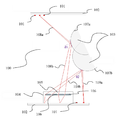
도 1은 본 발명의 실시예에 따른 시선 추적 디바이스(100)를 나타낸다. 이러한 시선 추적 디바이스(100)는 예를 들어, 턱받침을 포함하는 고정 지지대 상에 장착될 수 있거나 또는 휴대용 디바이스로서 구현될 수 있다. 기재의 나머지에서, 시선 추적 디바이스(100)가 휴대용 타입이지만, 하기에 기술되는 발명의 실시예들이 또한 고정 지지대 상에 장착되는 시선 추적 디바이스에 대해 구현될 수 있다고 가정된다.Figure 1 shows a
도 1에 표현된 시선 추적 디바이스(100)는 사용자의 왼쪽 눈에 대해 설계된다. 사용자의 오른쪽 눈에 대해 적응되는 시선 추적 디바이스는 도 1에 도시된 바와 같은 시선 추적 디바이스(100)에 대해 대칭적이다.The
시선 추적 디바이스(100)는 복수의 광원들(101)을 포함한다. 광원들(101)은 적외선 광원들 또는 IR 광원들(101)이다. IR 광원들(101)은 시선 추적 디바이스(100)의 프레임(102) 상에 위치된다. 이러한 방식으로, IR 광원들(101)이 눈(103)의 시야 주변에 위치되기 때문에 IR 광원들(101)은 시선 추적 디바이스(100)의 사용자의 눈(103)의 시야 내에 존재하지 않는다. 발명의 실시예에서, IR 광원들(101)은 디스크형, 직사각형 등과 같은 개구들일 수 있다.The line-of-
라이트-필드 카메라(104)는 시선 추적 디바이스(100)의 프레임(102)에 내장된다. 따라서, IR 광원들(102)에 대해서와 같이, 라이트-필드 카메라(104)는 눈(103)의 시야 주변에 위치된다. 라이트-필드 카메라(104)는 복수의 마이크로-렌즈들(106)을 포함하는 마이크로-렌즈 어레이(105)를 포함한다.The light-
디스크 부분(107a)은 오른쪽을 보는 눈(103)을 나타낸다. IR 광원(101)에 의해 방출되는 IR 광(108a)은 입사각(θ1)을 가지고 오른쪽을 보는 눈(107a) 상에서 반사한다. 반사된 IR 광(108b)은 마이크로-렌즈(106)를 통해 라이트-필드 카메라(104)에 의해 캡처된다.The
디스크 부분(107b)은 왼쪽을 보는 눈(103)을 나타낸다. IR 광원(101)에 의해 방출되는 IR 광(109a)은 입사각(θ2)을 가지고 왼쪽을 보는 눈(107b) 상에서 반사한다. 반사된 IR 광(109b)은 마이크로-렌즈(106)를 통해 라이트-필드 카메라(104)에 의해 캡처된다.The
라이트-필드 카메라(104)에 의해 캡처된 이미지들에서의 신호-대-잡음비를 증가시키고, 따라서, 획득되는 시선 추적 정보의 정확성의 증가를 제공하기 위해, 눈 상에서의 IR 광의 가능한 많은 반사를 생성하는 것이 관심대상이 된다(interesting). 이 목표를 달성하기 위해, IR 광원들(101)은, IR 광원(101)에 의해 방출되는 IR 광이 라이트-필드 카메라(104)의 센서의 적어도 하나의 픽셀에 의해 캡처되는 이러한 패턴으로 시선 추적 디바이스(100)의 프레임 주위에 모두 위치될 수 있다.To-noise ratio in the images captured by the light-
발명의 또다른 실시예에서, 사용자의 시선의 측정들의 감도를 증가시키기 위해, IR 광이 눈(103)의 표면 상에서 반사하는 동안 눈(103) 표면에 대해 법선인 벡터에 관한 추가 정보가 사용된다. 실제로, 눈(103)의 표면에 대해 법선인 벡터들에 대해 아는 것은 눈(103)의 배향을 계산할 수 있게 한다.In another embodiment of the invention, additional information is used about the vector, which is normal to the surface of the
눈(103)의 표면에 대해 법선인 벡터에 관한 정보의 이러한 부분은 IR 광을 편광시킴으로써 획득된다.This part of the information about the vector, which is normal to the surface of the
발명의 제1 실시예에서, IR 광원들(101)은 편광된 IR 광을 방출한다. IR 광의 편광은 편광 필터를 IR 광원들(101)에 구비함으로써 달성될 수 있다.In a first embodiment of the invention, the
도 2에 표현된 발명의 제2 실시예에서, 라이트-필드 카메라(200)의 마이크로-렌즈 어레이(202)의 마이크로 렌즈들(201)에는 편광 필터들이 구비된다. 예를 들어, 마이크로-렌즈들(201)에는 2가지 상이한 타입들의 편광 필터들(203, 204)이 구비된다. 예를 들어, 편광 필터들(203, 204)은 선형 편광 타입일 수 있고, 편광 필터들(203, 204)의 편광들은 서로 직교한다. 편광 필터들(203, 204)은 또한 원형 편광 타입일 수 있고, 편광 필터들(203, 204)의 편광들은 서로에 대해 반대의 의미이다.2, polarizing filters are provided in the
IR 광원들(101)에 의해 방출되는 비-편광된 IR 광의 안구 표면에서의 반사는 자연 편광을 제공할 수 있다. 실제로, 방출되는 IR 광의 입사각이 브루스터 각(Brewster angle)과 동일하도록 타겟화될 때, 반사된 IR 광의 편광은 평행 편광(parallel polarization)에 가까운데, 즉, 반사된 IR 광의 편광은 입사 IR 광과 반사된 IR 광에 의해 정의되는 평면(plan)에 대해 직교한다. 브루스터 각은 안구 상의 IR 광의 반사가 발생하는 위치에서 안구의 표면에 대한 법선 벡터에 따라 정의되며, 다른 매체가 공기임을 고려하면, 안구 투명 매체 물질(eyeball transparent medium material)의 인덱스에만 의존한다. 브루스터 각의 값은 그 자체가 측정되지 않으며, 광에 대한 효과들만이 편광 효과들을 통해 검출된다.Reflection at the ocular surface of the non-polarized IR light emitted by the IR
따라서, 발명의 또다른 실시예에서, IR 광원들(101)의 일부는 편광된 IR 광을 방출하는 반면, 다른 IR 광원들(101)은 비-편광된 IR 광을 방출한다. 비-편광된 IR 광을 방출하는 IR 광원들은 방출되는 IR 광의 입사각, 및 이 입사각에 따라 안구 상에서의 입사 IR 광의 반사가 반사되는 IR 광의 자연 편광을 초래하는 것을 알고 있는 것에 기초하여 선택된다.Thus, in another embodiment of the invention, some of the IR
발명의 또다른 실시예에서, 편광된 IR 광을 방출하는 IR 광원들(101)의 선택은 동적이며, 사용자의 눈의 현재 위치에 기초한다. 따라서, 사용자의 눈의 현재 위치에 따라, 주어진 IR 광원(101)은 편광된 IR 광을 방출하거나 또는 방출하지 않는다.In another embodiment of the invention, the selection of IR
사용자의 눈의 위치를 결정하기 위해, 라이트-필드 카메라(104, 200)에 의해 캡처되는 IR 광에 관한 정보가 이미지 프로세싱 디바이스에 전송된다. 본 발명의 실시예에서, 이미지 프로세싱 디바이스 및 시선 추적 디바이스(100)는 헤드 장착형 디바이스 또는 HMD와 같은 동일한 장치에 내장된다. 발명의 또다른 실시예에서, 이미지 프로세싱 디바이스 및 시선 추적 디바이스(100)는 서로 원격인 2개의 별개의 디바이스들이다. 시선 추적 디바이스(100)의 라이트-필드 카메라(104)에 의해 캡처되는 IR 광에 관한 정보는 케이블 또는 무선 통신을 통해 이미지 프로세싱 디바이스에 전송된다. 발명의 이러한 실시예에서, 시선 추적 디바이스(100)는 헤드 장착형 디바이스에 내장되는 반면, 이미지 프로세싱 디바이스는, 예를 들어, 컴퓨터에 내장된다.To determine the position of the user's eye, information about the IR light captured by the light-field camera 104,200 is sent to the image processing device. In an embodiment of the present invention, the image processing device and eye-tracking
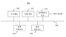
도 3은 본 발명의 실시예에 따른 시선 추적 디바이스(100)의 라이트-필드 카메라(104)에 의해 취득되는 라이트-필드 데이터를 프로세싱하기 위한 장치의 예를 예시하는 개략적 블록도이다.3 is a schematic block diagram illustrating an example of an apparatus for processing light-field data acquired by a light-
장치(300)는, 버스(306)에 의해 접속되는, 프로세서(301), 저장 유닛(302), 입력 디바이스(303), 디스플레이 디바이스(304), 및 인터페이스 유닛(305)을 포함한다. 물론, 컴퓨터 장치(300)의 구성 엘리먼트들은 버스 접속이 아닌 접속에 의해 접속될 수 있다.
프로세서(301)는 장치(300)의 동작들을 제어한다. 저장 유닛(302)은 프로세서(301)에 의해 실행될 적어도 하나의 프로그램, 및 라이트-필드 카메라(104)에 의해 취득되거나 시선 추적 디바이스(100)에 의해 제공되는 라이트-필드 데이터, 프로세서(301)에 의해 수행되는 계산들에 의해 사용되는 파라미터들, 프로세서(301)에 의해 수행되는 계산들의 중간 데이터 등을 포함하는 다양한 데이터를 저장한다. 프로세서(301)는 임의의 공지된 그리고 적절한 하드웨어, 또는 소프트웨어, 또는 하드웨어와 소프트웨어의 조합에 의해 형성될 수 있다. 예를 들어, 프로세서(301)는 프로세싱 회로와 같은 전용 하드웨어에 의해, 또는 이들의 메모리에 저장되는 프로그램을 실행하는 CPU(중앙 처리 장치)(Central Processing Unit)와 같은 프로그래밍가능한 프로세싱 유닛에 의해 형성될 수 있다.The
저장 유닛(302)은 컴퓨터-판독가능 방식으로 프로그램, 데이터 등을 저장할 수 있는 임의의 적절한 저장소 또는 수단에 의해 형성될 수 있다. 저장 유닛(302)의 예들은 반도체 메모리 디바이스들, 및 판독 및 기록 유닛에 로딩되는 자기, 광학, 또는 자기-광학 레코딩 미디어와 같은 비-일시적 컴퓨터-판독가능 저장 매체를 포함한다. 프로그램은 프로세서(301)가 학습 프로세스(learning process) 및 분류 프로세스를 수행하게 한다.The
입력 디바이스(303)는 커맨드들을 입력하기 위해 사용자에 의해 사용되기 위한, 키보드, 마우스와 같은 포인팅 디바이스 등에 의해 형성될 수 있다. 출력 디바이스(304)는 디스플레이하기 위한 디스플레이 디바이스, 예를 들어, 그래픽 사용자 인터페이스(Graphical User Interface)(GUI)에 의해 형성될 수 있다. 입력 디바이스(303) 및 출력 디바이스(304)는, 예를 들어, 터치스크린 패널에 의해 집적되어 형성될 수 있다.The
인터페이스 유닛(305)은 장치(300)와 외부 장치 사이에 인터페이스를 제공한다. 인터페이스 유닛(305)은 케이블 또는 무선 통신을 통해 외부 장치와 통신가능할 수 있다. 실시예에서, 외부 장치는 시선 추적 디바이스(100)를 내장하는 헤드 장착형 디바이스 또는 시선 추적 디바이스(100) 그 자체일 수 있다. 이 경우, 시선 추적 디바이스(100)의 라이트-필드 카메라(104)에 의해 취득되는 라이트-필드 데이터는 인터페이스 유닛(305)을 통해 시선 추적 디바이스(100)로부터 장치(300)로 입력되고, 이후 저장 유닛(302)에 저장될 수 있다.The
이 실시예에서, 장치(300)는, 그것이 시선 추적 디바이스(100)로부터 분리되어 있으며, 이들이 케이블 또는 무선 통신을 통해 서로 통신가능한 것으로서 예시적으로 논의된다.In this embodiment, the
학습 프로세스는 복수의 눈 위치들이 탐색되는 트레이닝 기간으로 구성되며, 학습 프로세스의 예는 효율적이고 정확한 임의의 다른 머신 학습 프로세스들 또는 신경망의 사용에 의존할 수 있다. 따라서, 트레이닝 기간 동안, IR 광이 눈에 의해 반사된 이후 라이트-필드 카메라(104)에 의해 캡처되는 IR 광원들(101)에 의해 방출되는 IR 광에 관한 데이터는 복수의 눈 위치들에 대해 장치(300)의 저장 유닛(302)에 저장된다. 이러한 저장된 위치들은 예를 들어 움직임 제어 타겟 또는 임의의 다른 캘리브레이션 수단의 사용을 통해 결정될 수 있다. 패턴은 라이트-필드 카메라(104)에 의해 캡처되는 다수의 이미지들 내의 복수의 반사 광 포인트들로서 정의되며, 캡처되는 이미지 내의 위치뿐만 아니라 반사 광 포인트들 각각의 강도가 장치(300)의 저장 유닛(302)에 저장된다.The learning process consists of a training period in which a plurality of eye positions are searched and an example of a learning process may be efficient and accurate depending on the use of any other machine learning processes or neural networks. Thus, during the training period, data relating to IR light emitted by the IR
이후, 프로세서(301)는 눈의 추정 위치를 결정하는 식별 프로세스를 실행한다. 식별 프로세스는 트레이닝 기간 이후 프로세서(301)에 의해 실시간으로 실행된다. 학습 프로세스의 결과들, 즉, 저장 유닛(302)에 저장되는 IR 광원들(101)에 의해 방출되는 IR 광들의 반사 패턴들을 사용하면, 실시간으로 사용자의 눈의 위치를 결정하는 것이 가능하다.Thereafter, the
발명의 상이한 실시예들에 따른 시선 추적 디바이스(100)는, 일단 프로세싱되면, 특히 아시아인의 눈과 같은 좁은 개구를 가지는 눈에 대해 정확하고 신뢰가능한 방식으로 시선의 추적을 가능하게 하는 캡처된 IR 광에 관한 정보를 제공한다. 이는 공간적 디스패리티(disparity)를 유도하는 라이트-필드 카메라(100)의 사용으로 인해 가능해진다. 시선 추적의 정확성은 공간적 디스패리티뿐만 아니라 편광에서의 디스패리티를 유도함으로써 증가한다.The
도 4는 헤드 장착형 디바이스(400)의 사용자의 각각의 왼쪽 눈(401a) 및 오른쪽 눈(401b)의 위치를 결정하기 위한 2개의 시선 추적 디바이스를 내장하는 헤드 장착형 디바이스(400)를 나타낸다.Figure 4 shows a head mounted
시선 추적 디바이스들은 복수의 광원들(402a 및 402b)을 포함한다. 광원들(402a, 402b)은 IR 광원들이다. IR 광원들(402a, 402b)은 헤드 장착형 디바이스(400)의 프레임(403) 상에 위치된다. 본 발명에 따른 헤드 장착형 디바이스(400)의 실시예에서, IR 광원들(402a, 402b)은 헤드 장착형 디바이스(400)의 프레임(403)의 림(404)에 내장된다. 이러한 방식으로, IR 광원들(402a, 402b)은 헤드 장착형 디바이스(400)의 사용자의 눈들(401a, 401b)의 시야 내에 있지 않다. 발명의 또다른 실시예에서, IR 광원들(402a, 402b)은 헤드 장착형 디바이스(400)의 프레임(403)의 측면부(405a, 405b)에 또한 내장된다.The eye tracking devices include a plurality of
발명의 실시예에서, 시선 추적 디바이스의 공간적 샘플링을 향상시키기 위해, 보조(secondary) IR 광원들(도면들에 나타나지 않음)이 헤드 장착형 디바이스(400)에 내장된다. 보조 IR 광원들에 의해 방출되는 IR 광은 헤드 장착형 디바이스(400)의 메인 렌즈 또는 메인 디스플레이 상에서 먼저 반사한다. 발명의 실시예에서, 보조 IR 광원들은 난형 기하학 형상을 나타내는 개구들일 수 있거나, 또는 격자들일 수 있다.In an embodiment of the invention, secondary IR light sources (not shown in the figures) are embedded in the head mounted
라이트-필드 카메라들(406a, 406b)은 헤드 장착형 디바이스(400)의 프레임(403)에 내장된다. 따라서, IR 광원들(402a, 402b)에 대해서와 같이, 라이트-필드 카메라들(406a, 406b)은 눈들(401a, 401b)의 시야 주변에 위치된다. 라이트-필드 카메라들(406a, 406b)은 복수의 마이크로-렌즈들을 포함하는 마이크로-렌즈 어레이를 포함한다.The light-
헤드 장착형 디바이스(400)의 또다른 실시예에서, 라이트-필드 카메라들(406a, 406b)은 헤드 장착형 디바이스(400)의 프레임(403)의 측면부들(405a, 405b) 상에 내장된다.In another embodiment of the head-mounted
사용자의 시선의 측정들의 감도를 증가시키기 위해, 헤드 장착형 디바이스(400)의 제1 실시예에서, IR 광원들(402a, 402b)은 편광된 IR 광을 방출한다. IR 광의 편광은 편광 필터들을 IR 광원들(402a, 402b)에 구비함으로써 달성될 수 있다.To increase the sensitivity of measurements of the user's line of sight, in the first embodiment of the head-mounted
헤드 장착형 디바이스(400)의 제2 실시예에서, 라이트-필드 카메라들(406a, 406b)의 마이크로-렌즈 어레이의 마이크로-렌즈들에는 편광 필터들이 구비된다.In a second embodiment of the head mounted
IR 광원들(101)에 의해 방출되는 비-편광된 IR 광의, 안구의 표면 상에서의 반사는 자연 편광을 제공할 수 있다. 따라서, 헤드 장착형 디바이스(400)의 제3 실시예에서, IR 광원들(402a, 402b)의 일부는 편광된 IR 광을 방출하는 반면, 다른 IR 광원들(402a, 402b)은 비-편광된 IR 광을 방출한다. 비-편광된 IR 광을 방출하는 IR 광원들은 방출되는 IR 광의 입사각, 및 이 입사각에 따라 안구 상의 입사 IR 광의 반사가 반사되는 IR 광의 자연 편광을 초래하는 것을 알고 있는 것에 기초하여 선택된다.The reflection of the non-polarized IR light emitted by the IR
헤드 장착형 디바이스(400)의 또다른 예에서, 편광된 IR 광을 방출하는 IR 광원들(402a, 402b)의 선택은 동적이며, 사용자의 눈의 현재 위치에 기초한다. 따라서, 사용자의 눈의 현재 위치에 따라, 주어진 IR 광원(402a, 402b)은 편광된 IR 광을 방출하거나 방출하지 않는다.In another example of the head mounted
사용자의 눈의 위치를 결정하기 위해, 라이트-필드 카메라들(406a, 406b)에 의해 캡처되는 IR 광에 관한 정보가 이미지 프로세싱 디바이스에 전송된다. 발명의 실시예에서, 이미지 프로세싱 디바이스가 헤드 장착형 디바이스(400)에 내장된다. 발명의 또다른 실시예에서, 이미지 프로세싱 디바이스 및 헤드 장착형 디바이스(400)는 서로 원격인 2개의 별개의 디바이스들이다. 라이트-필드 카메라들(406a, 406b)에 의해 캡처되는 IR 광에 관한 정보는 케이블 또는 무선 통신을 통해 이미지 프로세싱 디바이스에 전송된다.To determine the position of the user's eye, information about the IR light captured by the light-
본 발명이 특정 실시예들에 관해 전술되었지만, 본 발명은 특정 실시예들에 제한되지 않으며, 수정들은 본 발명의 범위 내에 있는 본 기술분야의 통상의 기술자에게 명백할 것이다.Although the present invention has been described above with reference to specific embodiments, the invention is not limited to the specific embodiments, and modifications will be apparent to those skilled in the art that are within the scope of the invention.
많은 추가적인 수정들 및 변형들이 그 자체를, 단지 예시로서 제공되며, 첨부된 청구항들에 의해서만 결정되는 발명의 범위를 제한하도록 의도되지 않는 이전의 예시적인 실시예들을 참조할 시에 본 기술분야에서 언급되는 것들로 제안할 것이다. 특히, 상이한 실시예들로부터의 상이한 특징들은, 적절한 경우 교환될 수 있다.It will be understood by those of ordinary skill in the art that many additional modifications and variations are within the spirit and scope of the invention as set forth in the following claims when referring to preceding exemplary embodiments that are provided by way of illustration only and are not intended to limit the scope of the invention as determined solely by the appended claims. I will suggest them as things. In particular, the different features from the different embodiments may be exchanged if appropriate.
Claims (9)
상기 시선 추적 디바이스의 사용자의 눈의 표면 상에 적외선 광을 투사하도록 배열되는 복수의 광원들, 및
상기 사용자의 눈의 표면에서 반사되는 적외선 광을 캡처(capture)하기 위한 라이트-필드 카메라(light-field camera)
를 포함하는 시선 추적 디바이스.As a gaze tracking device,
A plurality of light sources arranged to project infrared light onto the surface of a user's eye of the eye tracking device, and
A light-field camera for capturing infrared light reflected from the surface of the user's eye,
And an eye tracking device.
상기 시선 추적 디바이스는,
상기 시선 추적 디바이스의 사용자의 눈의 표면 상에 적외선 광을 투사하도록 배열되는 복수의 광원들, 및
상기 사용자의 눈의 표면에서 반사되는 적외선 광을 캡처하기 위한 라이트-필드 카메라
를 포함하는 헤드 장착형 디바이스.WHAT IS CLAIMED IS: 1. A head mounted device comprising at least one eye tracking device,
Wherein the gaze tracking device comprises:
A plurality of light sources arranged to project infrared light onto the surface of a user's eye of the eye tracking device, and
A light-field camera for capturing infrared light reflected from a surface of the user's eye
≪ / RTI >
Applications Claiming Priority (2)
| Application Number | Priority Date | Filing Date | Title |
|---|---|---|---|
| EP15306047.0 | 2015-06-30 | ||
| EP15306047.0A EP3112922A1 (en) | 2015-06-30 | 2015-06-30 | A gaze tracking device and a head mounted device embedding said gaze tracking device |
Publications (1)
| Publication Number | Publication Date |
|---|---|
| KR20170003442A true KR20170003442A (en) | 2017-01-09 |
Family
ID=53524700
Family Applications (1)
| Application Number | Title | Priority Date | Filing Date |
|---|---|---|---|
| KR1020160081139A KR20170003442A (en) | 2015-06-30 | 2016-06-28 | A gaze tracking device and a head mounted device embedding said gaze tracking device |
Country Status (5)
| Country | Link |
|---|---|
| US (1) | US20170004363A1 (en) |
| EP (1) | EP3112922A1 (en) |
| JP (1) | JP6850557B6 (en) |
| KR (1) | KR20170003442A (en) |
| CN (1) | CN106324831A (en) |
Families Citing this family (18)
| Publication number | Priority date | Publication date | Assignee | Title |
|---|---|---|---|---|
| US10120442B2 (en) * | 2016-12-21 | 2018-11-06 | Oculus Vr, Llc | Eye tracking using a light field camera on a head-mounted display |
| US10108261B1 (en) * | 2017-07-05 | 2018-10-23 | Oculus Vr, Llc | Eye tracking based on light polarization |
| CN107595291A (en) * | 2017-08-04 | 2018-01-19 | 上海志听医疗科技有限公司 | A kind of computer-readable medium for being installed to moving-vision recording equipment |
| CN107661085A (en) * | 2017-08-04 | 2018-02-06 | 上海志听医疗科技有限公司 | A kind of dynamic method with head position and stability data of real-time collecting eye |
| CN107661086A (en) * | 2017-08-04 | 2018-02-06 | 上海志听医疗科技有限公司 | A kind of system that eye movement data is collected using moving-vision recording equipment |
| CN107515466B (en) * | 2017-08-14 | 2019-11-26 | 华为技术有限公司 | A kind of eyeball tracking system and eyeball tracking method |
| US20190129174A1 (en) * | 2017-10-31 | 2019-05-02 | Google Llc | Multi-perspective eye-tracking for vr/ar systems |
| US10311584B1 (en) | 2017-11-09 | 2019-06-04 | Facebook Technologies, Llc | Estimation of absolute depth from polarization measurements |
| US10725292B2 (en) * | 2018-02-01 | 2020-07-28 | Varjo Technologies Oy | Gaze-tracking system and aperture device |
| EP3749172B1 (en) | 2018-02-09 | 2022-03-30 | Pupil Labs GmbH | Devices, systems and methods for predicting gaze-related parameters |
| EP3750028B1 (en) | 2018-02-09 | 2022-10-19 | Pupil Labs GmbH | Devices, systems and methods for predicting gaze-related parameters |
| WO2019154511A1 (en) | 2018-02-09 | 2019-08-15 | Pupil Labs Gmbh | Devices, systems and methods for predicting gaze-related parameters using a neural network |
| EP3582077A1 (en) | 2018-06-13 | 2019-12-18 | Tobii AB | Eye tracking device and method for manufacturing an eye tracking device |
| EP3627194A1 (en) * | 2018-09-20 | 2020-03-25 | Essilor International | An optical device with reduced reflection in deep red, near infrared and visible ranges |
| EP3912013A1 (en) | 2019-01-16 | 2021-11-24 | Pupil Labs GmbH | Methods for generating calibration data for head-wearable devices and eye tracking system |
| US11676422B2 (en) | 2019-06-05 | 2023-06-13 | Pupil Labs Gmbh | Devices, systems and methods for predicting gaze-related parameters |
| CN112578556B (en) * | 2019-09-27 | 2023-02-21 | 托比股份公司 | Eye tracking system for reducing unwanted reflections from optical devices |
| CN113138664A (en) * | 2021-03-30 | 2021-07-20 | 青岛小鸟看看科技有限公司 | Eyeball tracking system and method based on light field perception |
Family Cites Families (26)
| Publication number | Priority date | Publication date | Assignee | Title |
|---|---|---|---|---|
| FR2731896B1 (en) * | 1995-03-24 | 1997-08-29 | Commissariat Energie Atomique | DEVICE FOR MEASURING THE POSITION OF THE FIXING POINT OF AN EYE ON A TARGET, METHOD FOR LIGHTING THE EYE AND APPLICATION TO THE DISPLAY OF IMAGES OF WHICH THE IMAGES CHANGE ACCORDING TO THE MOVEMENTS OF THE EYE |
| US6871951B2 (en) * | 2000-06-23 | 2005-03-29 | E-Vision, Llc | Electro-optic lens with integrated components |
| US8228417B1 (en) * | 2009-07-15 | 2012-07-24 | Adobe Systems Incorporated | Focused plenoptic camera employing different apertures or filtering at different microlenses |
| US20110170061A1 (en) * | 2010-01-08 | 2011-07-14 | Gordon Gary B | Gaze Point Tracking Using Polarized Light |
| US8941559B2 (en) * | 2010-09-21 | 2015-01-27 | Microsoft Corporation | Opacity filter for display device |
| JP5570386B2 (en) * | 2010-10-18 | 2014-08-13 | パナソニック株式会社 | Attention state discrimination system, method, computer program, and attention state discrimination device |
| RU2612500C2 (en) * | 2011-07-14 | 2017-03-09 | Конинклейке Филипс Н.В. | System and method for remote measurement of optical focus |
| JP6094106B2 (en) * | 2011-09-26 | 2017-03-15 | 大日本印刷株式会社 | Gaze analysis apparatus, gaze measurement system, method, program, and recording medium |
| US8929589B2 (en) * | 2011-11-07 | 2015-01-06 | Eyefluence, Inc. | Systems and methods for high-resolution gaze tracking |
| US8913789B1 (en) * | 2012-01-06 | 2014-12-16 | Google Inc. | Input methods and systems for eye positioning using plural glints |
| US9116337B1 (en) * | 2012-03-21 | 2015-08-25 | Google Inc. | Increasing effective eyebox size of an HMD |
| WO2013167864A1 (en) | 2012-05-11 | 2013-11-14 | Milan Momcilo Popovich | Apparatus for eye tracking |
| JP5949319B2 (en) * | 2012-08-21 | 2016-07-06 | 富士通株式会社 | Gaze detection apparatus and gaze detection method |
| RU2015108858A (en) * | 2012-08-24 | 2016-10-20 | Ай Си ИНСАЙД ЛТД | Vision correction projector |
| EP2720464B1 (en) * | 2012-10-11 | 2018-01-10 | Sony Mobile Communications Inc. | Generating image information |
| US9110503B2 (en) * | 2012-11-30 | 2015-08-18 | WorldViz LLC | Precision position tracking device |
| US9665171B1 (en) * | 2013-03-04 | 2017-05-30 | Tobii Ab | Gaze and saccade based graphical manipulation |
| US9060710B2 (en) * | 2013-03-14 | 2015-06-23 | Amo Wavefront Sciences, Llc. | System and method for ocular tomography using plenoptic imaging |
| CN104113680B (en) * | 2013-04-19 | 2019-06-28 | 北京三星通信技术研究有限公司 | Gaze tracking system and method |
| WO2014186620A1 (en) * | 2013-05-15 | 2014-11-20 | The Johns Hopkins University | Eye tracking and gaze fixation detection systems, components and methods using polarized light |
| KR101926942B1 (en) * | 2013-09-03 | 2019-03-07 | 토비 에이비 | Portable eye tracking device |
| JP2015061595A (en) * | 2013-09-19 | 2015-04-02 | ジーエヌ オトメトリックス エー/エスGN Otometrics A/S | Headgear for observation of eye movements |
| CN105828700B (en) * | 2013-12-09 | 2018-07-06 | Smi创新传感技术有限公司 | It operates the method for eye tracking apparatus and eye tracking apparatus of the active illumination control for improved eyes tracking stability is provided |
| EP2886041A1 (en) * | 2013-12-17 | 2015-06-24 | ESSILOR INTERNATIONAL (Compagnie Générale d'Optique) | Method for calibrating a head-mounted eye tracking device |
| JP6329635B2 (en) * | 2014-02-25 | 2018-05-23 | アイベリファイ インコーポレイテッド | Eye tracking |
| NZ773822A (en) * | 2015-03-16 | 2022-07-29 | Magic Leap Inc | Methods and systems for diagnosing and treating health ailments |
-
2015
- 2015-06-30 EP EP15306047.0A patent/EP3112922A1/en active Pending
-
2016
- 2016-06-23 JP JP2016124627A patent/JP6850557B6/en active Active
- 2016-06-27 CN CN201610478798.XA patent/CN106324831A/en active Pending
- 2016-06-28 KR KR1020160081139A patent/KR20170003442A/en not_active Application Discontinuation
- 2016-06-30 US US15/197,927 patent/US20170004363A1/en not_active Abandoned
Also Published As
| Publication number | Publication date |
|---|---|
| JP2017012746A (en) | 2017-01-19 |
| JP6850557B2 (en) | 2021-03-31 |
| CN106324831A (en) | 2017-01-11 |
| EP3112922A1 (en) | 2017-01-04 |
| JP6850557B6 (en) | 2021-05-26 |
| US20170004363A1 (en) | 2017-01-05 |
Similar Documents
| Publication | Publication Date | Title |
|---|---|---|
| KR20170003442A (en) | A gaze tracking device and a head mounted device embedding said gaze tracking device | |
| US10878236B2 (en) | Eye tracking using time multiplexing | |
| US10845606B1 (en) | Eye tracking for a head mounted display including a pancake lens block | |
| US10429927B1 (en) | Eye tracking for a head mounted display including a pancake lens block | |
| US20170131765A1 (en) | Eye tracking using optical flow | |
| US10429657B1 (en) | Eye tracking for a head mounted display including a pancake lens block | |
| WO2017013913A1 (en) | Gaze detection device, eyewear terminal, gaze detection method, and program | |
| US10503248B1 (en) | Selective color sensing for motion tracking | |
| US10585477B1 (en) | Patterned optical filter for eye tracking | |
| CN108351514A (en) | Use the eye tracks of structure light | |
| EP2889733A1 (en) | Information input device | |
| US20180039327A1 (en) | Information processing apparatus, information processing method, and program | |
| KR20160075571A (en) | System and method for reconfigurable projected augmented/virtual reality appliance | |
| US11847257B2 (en) | Position tracking system for head-mounted display systems | |
| US20210096368A1 (en) | Head-mounted display apparatus and method employing dynamic eye calibration | |
| US11747626B1 (en) | Display system with extended display area | |
| US11327329B2 (en) | Information processing apparatus and surface roughness acquisition method | |
| US11016303B1 (en) | Camera mute indication for headset user | |
| WO2023055732A1 (en) | Position tracking systems and methods for head-mounted display systems | |
| US20220413284A1 (en) | Interferometric structured illumination for depth determination | |
| US20190018216A1 (en) | Devices and methods for lens alignment based on encoded color patterns | |
| WO2024058934A1 (en) | Position tracking systems and methods for head-mounted display systems | |
| JP2022177067A (en) | Device, method and program for identifying position of cornea center of eye |
Legal Events
| Date | Code | Title | Description |
|---|---|---|---|
| WITB | Written withdrawal of application |