KR20170003207U - A draining trap - Google Patents
A draining trap Download PDFInfo
- Publication number
- KR20170003207U KR20170003207U KR2020170004476U KR20170004476U KR20170003207U KR 20170003207 U KR20170003207 U KR 20170003207U KR 2020170004476 U KR2020170004476 U KR 2020170004476U KR 20170004476 U KR20170004476 U KR 20170004476U KR 20170003207 U KR20170003207 U KR 20170003207U
- Authority
- KR
- South Korea
- Prior art keywords
- drainage
- sewage
- drain
- drain trap
- pipe
- Prior art date
Links
Images


Classifications
-
- E—FIXED CONSTRUCTIONS
- E03—WATER SUPPLY; SEWERAGE
- E03F—SEWERS; CESSPOOLS
- E03F5/00—Sewerage structures
- E03F5/04—Gullies inlets, road sinks, floor drains with or without odour seals or sediment traps
- E03F5/0407—Floor drains for indoor use
-
- E—FIXED CONSTRUCTIONS
- E03—WATER SUPPLY; SEWERAGE
- E03F—SEWERS; CESSPOOLS
- E03F5/00—Sewerage structures
- E03F5/04—Gullies inlets, road sinks, floor drains with or without odour seals or sediment traps
- E03F2005/0416—Gullies inlets, road sinks, floor drains with or without odour seals or sediment traps with an odour seal
- E03F2005/0418—Gullies inlets, road sinks, floor drains with or without odour seals or sediment traps with an odour seal in the form of a bell siphon
Abstract
본 고안은 역류방지 기능을 갖춘 배수트랩에 관한 것으로, 이의 목적은 배출되는 하수에 의해 배수유도통 하단부가 선택적으로 개폐될 수 있도록 하여 장기간 집을 비워 실내 바닥에 물을 버리지 않아도 배수트랩의 내부에 잔류 하수가 증발되지 않고 배수관의 악취 및 해충이 실내로 유입(역류)되는 것을 근본적으로 방지할 수 있도록 하는 것이다.
이를 위해 본 고안에 따른 『역류방지 기능을 갖춘 배수트랩』에 의하면; 배수관(P)에 끼워져 결합되도록 중앙에는 통-결합구(110)가 하부로 연장 형성되며 상면은 가장자리에서 중앙부로 갈수록 하향 경사진 배수트랩 본체(100)와; 상하부가 개방된 통 형상으로 이루어지며, 상단부(410)는 배수트랩 본체(100)의 통-결합구(110) 상단 내벽에 나사 결합식으로 조립되고, 하단부(420)는 상기 통-결합구(110) 하측의 내부 중앙으로 연장되어 배수를 안내하는 배수유도통(400)과; 벽면(310)과 밑면(320)을 가지며 상부가 개방된 통 형상으로 이루어지며, 배수트랩 본체(100)의 통-결합구(110) 하단부에 벽면(310) 상단부가 승하강 가능하게 배치되고, 벽면(310) 중앙부위에는 복수개의 배수창(330)이 천공되며, 배수창(330) 높이보다 낮은 공간에 일정높이의 하수가 채워져 잔류하는 하수잔류통(300)과; 상단은 하수잔류통(300)의 상단부 외향플랜지(340)에 걸려 지지되고 하단은 통-결합구(110)의 하단 내벽 내향플랜지(112)에 걸려 지지되어, 배출 하수의 하중에 의해 하수잔류통(300)의 밑면(320)이 배수유도통(400)의 하단부(420)를 선택적으로 개폐할 수 있도록 상기 하수잔류통(300)을 상측 방향으로 탄성 지지하는 코일스프링(500)과; 하수 배출이 완료되어 코일스프링(500)의 탄성 지지력에 의한 하수잔류통(300)의 최대 승강을 제한할 수 있도록 배수통(300)의 벽면(310) 하단부에 띠 형태로 형성된 안착홈(350)에 마련되어 통-결합구(110)의 내향플랜지(112)에 걸리는 오링부재(600)를; 구비하는 것을 특징으로 한다.The present invention relates to a drainage trap having a backflow prevention function, and its object is to provide a drainage trap capable of selectively opening and closing the drainage induction pipe by the discharged sewage, And it is possible to fundamentally prevent odors and pests of the drain pipe from flowing into the room (reverse flow) without the sewage being evaporated.
For this purpose, according to the "drain trap with backflow prevention function" according to the present invention, A drainage trap body 100 is formed at the center so that the drainage pipe P is inserted into the drainage pipe P and the drainage trap body 110 extends downward and the upper surface thereof is inclined downward from the edge toward the center. The upper end portion 410 is assembled into the inner wall of the upper end of the tub-coupling hole 110 of the drain trap body 100 in a threaded manner and the lower end portion 420 is assembled into the tub- 110), a drain guide pipe (400) extending to an inner center of the lower side and guiding drainage; The upper end of the wall surface 310 is movable upward and downward at a lower end of the tub-coupling hole 110 of the drain trap body 100, A plurality of drainage windows 330 are formed on a central portion of the wall surface 310 and the remaining drainage tanks 300 are filled with sewage having a predetermined height in a space lower than the height of the drainage windows 330; The upper end is hooked on the upper end outward flange 340 of the sewage retainer 300 and the lower end is hooked on the lower end inner wall inward flange 112 of the barrel-coupling hole 110, A coil spring 500 elastically supporting the sewage remaining cylinder 300 upward to selectively open and close the lower end portion 420 of the water discharge induction cylinder 400; A seating groove 350 formed in the shape of a strip at the lower end of the wall surface 310 of the drain canister 300 so as to limit the maximum lift of the sewage retainer 300 due to the elastic support force of the coil spring 500 after the discharge of sewage is completed, An O-ring member 600 which is provided on the inward flange 112 of the barrel-engagement hole 110; .
Description
본 고안은 배수트랩에 관한 것으로; 더욱 상세하게는 화장실(욕실)이나 베란다 등의 바닥에 설치되어 배수관으로 물을 빠져나가게 안내하면서 배수관 악취는 유입되지 않게 하는 『역류방지 기능을 갖춘 배수트랩』에 관한 것이다.The present invention relates to drainage traps; More particularly, the present invention relates to a drain trap provided with a backflow preventing function, which is provided on the floor of a bathroom (bathroom) or a veranda to guide water out of the drain pipe while preventing the drain pipe odor from being introduced.
일반적으로 다세대 주택, 아파트 등 공동주택뿐만 아니라 일반 가정에서는 배출되는 각종 하수를 집수 처리할 수 있도록 집수조가 설치되며, 각 가정의 욕실 또는 베란다 등의 바닥과 집수조는 배수관(배수 파이프)을 통해 연결되어 있다. 이러한 배수관에는 생활 주변의 화장실, 욕조 등과 같이 많은 양의 물과 오물이 함께 내려감으로써 냄새(악취)가 역류할 수 있는데, 냄새(악취) 역류를 방지하기 위해 화장실(욕실)이나 베란다 등의 바닥에 설치되는 것이 배수트랩이다.Generally, a water collecting tank is installed to collect various kinds of sewage discharged from not only common houses such as multi-family houses and apartments but also households. The bottom of each family bathroom or veranda and the collecting tank are connected through a water pipe (drain pipe) have. In such a drain pipe, a large amount of water and dirt, such as toilet and bathtubs around the living room, together with the odor (odor) can flow backward. In order to prevent backflow of odor (odor) The drain trap is installed.
종래 배수트랩은 도 1에 도시한 바와 같이, 배수관(P)의 직상부에 설치되며 중앙에 통결합구(2)가 천공된 배수트랩 본체(1)와, 이 배수트랩 본체(1)의 통결합구(2)에 하부로 연장되면서 탈착 가능하게 설치되며 저부에 일정높이의 물이 채워져 잔류하는 배수잔류통(3)과, 배수트랩 본체(1)의 통결합구(2)에 하부로 연장되면서 탈착 가능하게 설치되며 하단부는 배수잔류통(3) 내부공간에 이격되게 수용되는 배수유도통(4)과, 배수트랩 본체(1)의 상부를 덮도록 설치되며 전역에 걸쳐 배수홀(5a)이 천공된 거름커버(5)를 갖추고 있다. 따라서 물은 거름커버(5)의 배수홀(5a)들을 통해 배수트랩 본체(1) 중앙부로 모이면서 배수유도통(4)을 경유하며, 계속하여 배수잔류통(3)의 벽면에 천공된 배수창(3a)을 통해 배수관(P)으로 빠져나간다(도 1의 화살표 방향 참조). 배수 과정에서 머리카락과 같은 오물은 거름커버(5)에서 1차로 걸러지고 배수유도통(4)과 배수잔류통(3) 내부에서도 걸러진다. 그리고 배수잔류통(3) 바닥에는 일정높이의 물이 채워져 배수유도통(4) 하단이 항상 잠긴 상태로 유지되기 때문에, 배수관(P)으로부터의 냄새(악취) 역류가 방지된다.1, a conventional drain trap is provided with a
그러나 이러한 종래 배수트랩 구조에서는 도 2에 도시한 바와 같이, 배수잔류통(3)에 잔류하던 오수가 증발하게 되면 배수관(P)의 냄새가 실내로 유입될 수 있다. 즉, 배수잔류통(3)은 실내와 직접 연통되기 때문에 장기간 집을 비워 화장실 바닥에 물을 버리지 않으면 배수잔류통(3) 바닥의 잔류 오수가 증발하게 되며, 오수가 증발된 배수잔류통(3)은 배수관(P)과 실내를 직접 연통시켜 에어 통로 역할을 한다. 따라서 배수관(P)의 역한 냄새(악취)가 배수잔류통(3)과 배수유도통(4)을 통해 실내로 역류하며(도 2의 화살표 방향 참조), 이를 통해 냄새 이외에도 해충이 들어오는 경우도 빈번하게 발생하는 단점이 있다.However, in such a conventional drain trap structure, as shown in FIG. 2, if the wastewater remaining in the
본 고안은 이러한 문제점을 해결하기 위한 것으로; 본 고안의 목적은 배출 하수의 하중에 의해 배수유도통 하단부가 선택적으로 개폐될 수 있도록 하여 장기간 집을 비워 실내 바닥에 물을 버리지 않아도 배수트랩의 내부에 잔류 하수가 증발되지 않으며 배수관의 악취 및 해충 등이 실내로 유입(역류)되는 것을 근본적으로 방지할 수 있는 『역류방지 기능을 갖춘 배수트랩』을 제공하는 것이다.The present invention addresses this problem. The purpose of the present invention is to enable the lower end of the drainage induction pipe to be selectively opened and closed by the discharge sewage load so that the residual sewage does not evaporate inside the drainage trap even if the house is vacated for a long time without draining water on the indoor floor, (Drainage trap having a backflow prevention function) which can fundamentally prevent the inflow (backward flow) of the air into the room.
이러한 목적을 달성하기 위한 본 고안은;The present invention for achieving this object is as follows.
배수관이 설치된 욕실이나 베란다 등의 바닥에 매립 설치되어 배수를 안내하면서 역류방지 기능을 갖춘 배수트랩에 있어서;1. A drainage trap having a backflow preventing function while being installed on a floor of a bathroom or a veranda equipped with a drain pipe and guiding drainage;
상기 배수트랩이; 상기 배수관에 끼워져 결합되도록 중앙에는 통-결합구가 하부로 연장 형성되며 상면은 가장자리에서 중앙부로 갈수록 하향 경사진 배수트랩 본체와; 상하부가 개방된 통 형상으로 이루어지며, 상단부는 상기 배수트랩 본체의 통-결합구 상단 내벽에 나사 결합식으로 조립되고, 하단부는 상기 통-결합구 하측의 내부 중앙으로 연장되어 배수를 안내하는 배수유도통과; 벽면과 밑면을 가지며 상부가 개방된 통 형상으로 이루어지며, 상기 배수트랩 본체의 통-결합구 하단부에 벽면 상단부가 승하강 가능하게 배치되고, 벽면 중앙부위에는 복수개의 배수창이 천공되며, 상기 배수창 높이보다 낮은 공간에 일정높이의 하수가 채워져 잔류하는 하수잔류통과; 상단은 상기 하수잔류통의 상단부 외향플랜지에 걸려 지지되고 하단은 상기 통-결합구의 하단 내벽 내향플랜지에 걸려 지지되어, 배출 하수의 하중에 의해 상기 하수잔류통의 밑면이 상기 배수유도통의 하단부를 선택적으로 개폐할 수 있도록 상기 하수잔류통을 상측 방향으로 탄성 지지하는 코일스프링과; 하수 배출이 완료되어 상기 코일스프링의 탄성 지지력에 의한 상기 하수잔류통의 최대 승강을 제한할 수 있도록 상기 배수통의 벽면 하단부에 띠 형태로 형성된 안착홈에 마련되어 상기 통-결합구의 내향플랜지에 걸리는 오링부재를; 구비하는 것을 특징으로 한다. The drain trap; A drain trap body extending downward from the center and having an upper surface inclined downward from an edge toward a center of the drain trap body so as to be inserted into the drain pipe; And an upper end portion thereof is assembled to the inner wall of the upper end of the barrel-coupling hole of the drain trap body in a screw-fitting manner, and a lower end portion thereof extends to the inner center of the lower portion of the barrel- Induction passage; Wherein a top wall of the drain trap body is upwardly and downwardly movable at a lower end portion of the drain trap body, and a plurality of drain holes are drilled on a central portion of the wall, Residual sewage residue passing through the lower space filled with sewage of a certain height; The lower end of the sewage retaining cylinder is hooked on an inward flange on the upper end of the sewage retaining cylinder and the lower end is hooked on the lower end inner wall inward flange of the tub- A coil spring for elastically supporting the sewage retainer in an upward direction so as to be selectively opened and closed; And an upper end of the lower end of the drain canister is provided with a groove formed in the lower end portion of the wall of the drain tank so as to limit the maximum lift of the sewage retainer by the elastic support force of the coil spring. Member; .
상기와 같은 구성으로 이루어진 본 고안에 따른 『역류방지 기능을 갖춘 배수트랩』에 의하면; 배출 하수의 하중에 의해 하수잔류통의 밑면이 배수유도통의 하단부를 선택적으로 개폐함으로써, 장기간 집을 비워 실내 바닥에 물을 버리지 않아도 배수트랩의 하수잔류통에 잔류하는 오수가 증발되지 않으며 배수관의 악취 및 해충이 실내로 유입(역류)되는 것을 효과적으로 방지할 수 있는 작용효과가 있다. 즉, 배수가 이루어지지 않으면 코일스프링의 탄성 지지력에 의해 잔수가 채워진 하수잔류통이 승강하여 배수유도통의 하단부를 폐쇄함으로써 실내와 배수관측의 직접적인 연통을 차단하며, 이것에 의해 배수관의 악취가 실내로 유입되는 것을 근본적으로 차단할 수 있는 장점이 있다.According to the drain trap having the backflow prevention function according to the present invention constructed as described above, The bottom surface of the sewage retaining pail selectively opens and closes the lower end of the drainage inducing pail by the load of discharged sewage so that the sewage remaining in the sewage retaining pail of the drainage trap is not evaporated without draining water on the floor of the room for a long time, And the effect that the pest can be effectively prevented from flowing into the room (reverse flow). That is, if the drainage is not performed, the residual water tank filled with the residual water is lifted by the elastic supporting force of the coil spring to close the lower end of the drain water guiding cylinder, thereby preventing direct communication between the room and the drain water observation side. It is possible to fundamentally block the inflow of dust into the air.
특히, 본 고안에 따른 『역류방지 기능을 갖춘 배수트랩』에 의하면; 하수 배출이 완료되어 하수잔류통이 승강하면 탄성 재질의 오링부재가 통-결합구의 내향플랜지에 밀착됨으로써, 통-결합구와 하수잔류통의 벽면 사이틈을 보다 견실하게 폐쇄할 수 있는 이점이 있다. 이로 인해, 배수관 악취는 물론이며 장마철에 배수관을 통해 역류할 수 있는 오/폐수가 배수트랩으로 유입되는 것을 완전하게 예방하는 장점이 있다.Particularly, according to the "drain trap having a backflow prevention function" according to the present invention, When the sewage drainage is completed and the sewage retaining cylinder ascends and descends, an elastic material o-ring member is brought into close contact with the inward flange of the barrel-to-barrel so that the clearance between the barrel-binding barrel and the wall surface of the sewage retaining barrel can be more firmly closed. As a result, there is an advantage that it completely prevents the flow of ozone / wastewater, which can flow back through the drain pipe to the drain trap, in the rainy season as well as the drain pipe odor.
도 1은 종래 배수트랩 내부 구조를 보인 단면도이다.
도 2는 종래 배수트랩에서 배수관 내부 악취가 실내로 역류하는 과정을 보인 것이다.
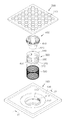
도 3은 본 고안에 따른 배수트랩의 전체적인 구조를 보인 분해사시도이다.
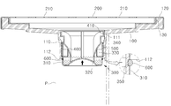
도 4는 도 3의 Ⅳ - Ⅳ선에 따른 단면도로, 본 고안에 따른 배수트랩의 내부구조를 보인 것이다.
도 5는 본 고안에 따른 배수트랩의 구성을 구성 분해 단면도이다.
도 6과 도 7은 본 고안에 따른 배수트랩의 동작 상태를 보인 것으로; 도 6은 배출 하수에 의해 배수유도통이 개방된 상태를 보인 것이고, 도 7은 배수유도통이 닫힌 상태를 보인 것이다.1 is a cross-sectional view showing a conventional inner structure of a drain trap.
2 is a view showing a process in which a malodor in a drain pipe reversely flows into a room in a conventional drain trap.
3 is an exploded perspective view showing the overall structure of a drain trap according to the present invention.
FIG. 4 is a cross-sectional view taken along line IV-IV in FIG. 3, showing the internal structure of the drain trap according to the present invention.
5 is a cross-sectional view of the drain trap according to the present invention.
FIGS. 6 and 7 show operation states of the drain trap according to the present invention; FIG. 6 shows a state in which the drainage induction cylinder is opened by the discharge sewage, and FIG. 7 shows the state in which the drainage induction cylinder is closed.
다음에는 이와 같이 구성된 본 고안에 따른 하나의 바람직한 실시 예를 첨부도면을 참조하여 상세히 설명한다. 첨부도면을 간략히 설명하면, 도 3 내지 도 5는 본 고안에 따른 배수트랩의 구성을 보인 것이고, 도 6과 도 7은 본 고안에 따른 배수트랩의 동작 상태를 보인 것이다.DETAILED DESCRIPTION OF THE PREFERRED EMBODIMENTS Reference will now be made in detail to the preferred embodiments of the present invention, examples of which are illustrated in the accompanying drawings. FIGS. 3 to 5 show the construction of the drain trap according to the present invention, and FIGS. 6 and 7 show operation states of the drain trap according to the present invention.
<본 고안에 따른 배수트랩의 구성 설명>≪ Construction of drain trap according to the present invention >
본 고안에 따른 배수트랩은 배수관이 설치된 욕실(화장실)이나 베란다 등의 바닥에 배수를 안내하면서 냄새 역류를 방지하기 위해 매립 설치되는 것으로; 도 3과 도 4에 도시한 바와 같이, 대략 사각 형태로 이루어지며 중앙에 통-결합구(110)가 하부로 연장되게 이루어진 배수트랩 본체(100)와, 이 배수트랩 본체(100)의 상부를 덮는 거름커버(200)와, 상기 배수트랩 본체(100)의 통-결합구(110)에 나사 결합방식으로 조립되어 배수를 안내하는 배수유도통(400)과, 배수트랩 본체(100)의 통-결합구(110) 하단에 상단부가 승하강 가능하게 배치되며 벽면(310)부에는 배수창(330)이 천공된 하수잔류통(300)과, 하수잔류통(300)의 벽면(310)의 하단부에 띠 형태로 마련된 오링부재(600)와, 배수되는 하수의 하중에 의해 하수잔류통(300)의 밑면(320)이 배수유도통(400)의 하단부(420)를 선택적으로 개폐할 수 있도록 하수잔류통(300)을 상측방향으로 탄성 지지하는 코일스프링(500)을 갖추고 있는데, 각 구성요소들의 상세한 구조는 다음과 같다.The drain trap according to the present invention is installed to prevent the backflow of odor while guiding drainage to the bottom of a bathroom (toilet) or a veranda equipped with a drain pipe. As shown in FIGS. 3 and 4, a drain trap
도 4와 도 5를 참조하면; 배수트랩 본체(100)는 배수관(P)이 설치된 욕실(화장실)이나 베란다 등의 바닥에 매입되어 배수관(P)과 접속될 수 있도록 구성되는데, 이것은 성형이 용이한 합성수지 재질로 이루어지며 이의 가장자리는 내부식성이 우수한 스테인리스 커버재(120)로 덮여 있다. 또한, 배수트랩 본체(100)의 상면은 배수가 용이하도록 가장자리에서 중앙부로 갈수록 하향 경사지게 이루어져 있으며, 배수트랩 본체(100)의 중앙에는 통-결합구(110)가 하부로 연장되게 형성되어 있다. 통-결합구(110)는 배수관(P)에 수용 배치되게 되며, 이의 상단 내벽에는 배수유도통(400)의 착탈 결합을 위해 암나사(111)가 형성되어 있다. 또한, 통-결합구(110)의 개방된 하단부에는 내향플랜지(112)가 형성되어 있는데, 이것은 코일스프링(500)의 하단부를 지지하기 위한 것이다. 미설명부호 '130'은 배수트랩 본체(100)의 상면 가장자리를 따라 형성된 단차턱으로, 이의 내측으로 거름커버(200)가 흔들림없이 견실하게 안착 될 수 있다.4 and 5, The drain trap
거름커버(200)는 배수트랩 본체(100)의 상면을 덮도록 설치되는 것으로, 전역에 걸쳐서 배수홀(210)들이 천공되어 있다. 이에 따라 욕실이나 베란다 등의 바닥에 흘려진 물은 거름커버(200)의 배수홀(210)들을 통해 배수관(P)측으로 유입되며, 유입과정에서 머리카락과 같은 오물이 일차로 걸러지게 된다. 이러한 거름커버(200)는 내부식성이 우수한 스테인리스 스틸 플레이트를 프레스 가공하여 이루어지며, 배수트랩 본체(100) 상면의 단차턱(130) 내측에 배치된다.The
배수유도통(400)은 도 4와 도 5에 도시한 바와 같이, 통-결합구(110) 상단 내벽에 상단부(410)가 나사 결합식으로 조립되며, 이의 하단부(420)는 하수잔류통(300) 내부공간에 수용된다. 배수유도통(400)의 하단(420)은 하수잔류통(300)의 배수창(330) 보다 아래측에 위치하도록 연장되어 있어서, 물은 배수유도통(400)의 하단부(420)를 U형태로 돌아서 배수창(330)으로 빠져나가게 되는데, 이를 통해 머리카락과 같은 오염물이 걸러질 수 있으며 앞서 기술한 바와 같이 하수잔류통(300) 저부에 잔류하는 물에 의해 냄새 역류를 차단할 수 있다. 그리고 배수유도통(400)에 걸린 오물을 제거하고자 하는 경우에는 배수유도통(400)을 풀리는 방향으로 돌려 빼낼 수 있다.4 and 5, the
하수잔류통(300)은 상부가 개방되고 벽면(310)과 밑면(320)을 갖는 컵 형상으로 이루어져 있으며, 배수트랩 본체(100)의 통-결합구(110) 하단부에 상단부가 승하강 가능하게 배치되면서 하부로 연장된다. 하수잔류통(300)의 상단부에는 외향플랜지(340)가 마련되는데, 이를 통해 통-결합구(110)에서 이탈되는 것을 방지하면서 코일스프링(500)을 견실하게 설치할 수 있다. 그리고 하수잔류통(300)의 벽면(310)에는 밑면(320)에서부터 일정한 높이로 복수개의 배수창(330)이 천공되어 있어서, 배수가 진행되면서도 일정높이의 하수가 채워져 잔류하게 된다. 이러한 구조는 배수가 더 이상 이루어지지 않으면 잔류하는 하수를 통해 배수관(P)측의 냄새 역류를 차단하기 위함이다. 또한, 하수잔류통(300)은 코일스프링(500)의 탄성 지지력에 의해 올라가 밑면(320)이 배수유도통(400)의 하단부(420)를 폐쇄할 수 있는 구조인데, 이는 하수잔류통(300) 저부에 고인 하수의 증발을 방지하면서 배수관(P)측의 냄새 역류를 근본적으로 차단하기 위한 것이다. 이러한 하수잔류통(300)의 밑면(320) 중앙은 상측으로 볼록한 돔 형상으로 이루어져 있다.The
코일스프링(500)은 상단이 하수잔류통(300)의 상단부(외향플랜지;340)에 걸려 지지되고 하단은 통-결합구(110)의 하단 내벽(내향플랜지;112)에 걸려 지지됨으로써, 하수잔류통(300)의 밑면(320)이 배출되는 하수의 하중에 의해 배수유도통(400)의 하단부(420)를 선택적으로 개폐할 수 있도록 하수잔류통(300)을 상측방향으로 탄성 지지하게 된다. 즉, 하수잔류통(300) 밑면(320)은 배수가 이루어지지 않으면 코일스프링(500)의 탄성 복원력에 의해 상측으로 올라가 배수유도통(400)의 하단(420)과 접하여 이를 폐쇄하게 된다. 반면에, 배수가 이루어지면 하수의 하중이 코일스프링(500)의 탄성력을 이기면서 하수잔류통(300)을 아래로 눌러 배수유도통(400)의 하단(420)이 개방되게 된다. 따라서 배출되는 하수는 배수유도통(400)과 하수잔류통(300)의 배수창(330)을 통해 배수관(P)으로 빠져나가게 된다. 이러한 하수잔류통(300)의 개폐 동작은 이를 상측으로 지지하는 코일스프링(500)의 탄성력에 의해 결정된다.The upper end of the
한편, 오링부재(600)는 하수 배출이 완료되어 코일스프링(500)의 탄성 지지력에 의한 하수잔류통(300)의 최대 승강을 제한할 수 있도록 하수잔류통(300)의 벽면(310) 하단부에 띠 형태로 배치된다. 즉, 하수 배출이 완료되면 오링부재(600)가 통-결합구(110)의 내향플랜지(112)에 걸릴 때까지 하수잔류통(300)이 승강하게 된다. 본 고안의 실시 예에서 오링부재(600)는 탄성재질의 오-링으로 이루어지며, 하수잔류통(300)의 벽면(310) 하단부에 띠 형태로 형성된 안착홈(350)에 설치하였다. 따라서 하수잔류통(300)의 최대승강시 통-결합구(110)와 하수잔류통(300)의 벽면(310) 사이틈을 견실하게 폐쇄할 수 있다.The O-
<본 고안에 따른 배수트랩의 작동 및 이에 따른 작용효과 설명>≪ Operation of drain trap according to the present invention and description of operation effect thereof >
다음에는 이와 같이 구성된 본 고안에 따른 배수트랩의 작동 및 이에 따른 작용효과를 도 6과 도 7을 참조하여 설명한다.Next, the operation of the drain trap constructed as described above and the operation and effect of the drain trap will be described with reference to FIGS. 6 and 7. FIG.
먼저, 욕실이나 베란다 등에서 바닥에 물을 버리면, 배수되는 하수는 거름커버(200)의 배수홀(210)들을 통해 배수트랩 본체(100) 중앙부로 모이면서 배수유도통(400)으로 빠져나간다.First, when the water is drained from the bottom of a bathroom or a veranda, the drained sewage collects in the
도 6에 도시한 바와 같이, 배수유도통(400)으로 하수가 유입되면 이의 하중에 의해 코일스프링(500)를 압축시키면서 하수잔류통(300)이 하강하여 배수유도통(400)의 하단부(420)를 개방한다. 따라서 하수는 하수잔류통(300)의 벽면(310)에 천공된 배수창(330)을 통해 배수관(P)으로 빠져나간다. 하수잔류통(300)의 밑면(320) 중앙은 상측으로 볼록한 돔 형상이기 때문에 배수가 원활하게 이루어진다.6, when the sewage is introduced into the
그리고 도 7에 도시한 바와 같이, 배수가 완료되어 배수유도통(400)의 물이 대부분 빠져나가면 코일스프링(500)의 탄성 복원력에 의해 하수잔류통(300)은 다시 올라가 밑면(320)이 배수유도통(400)의 하단(420)과 접하여 이를 폐쇄한다. 따라서 배수관(P)과 실내의 연통이 근본적으로 차단됨으로써, 배수관(P)측의 역한 냄새가 역류하지 못하게 된다. 특히, 배수유도통(400) 하단부가 차단되기 때문에, 하수잔류통(300) 저부에 잔류하는 하수 역시 증발하지 않고 그대로 유지되어 배수관(P)측의 냄새 역류를 차단할 수 있다.7, when the drainage is completed and most of the water in the
아울러, 하수잔류통(300)은 오링부재(600)가 통-결합구(110)의 내향플랜지(112)에 밀착될 때까지 승강되는데, 이로 인해 통-결합구(110)와 하수잔류통(300)의 벽면(310) 사이틈이 완전하게 차단됨으로써, 배수관(P) 악취는 물론이며 장마철에 배수관(P)을 통해 역류할 수 있는 오/폐수가 배수트랩으로 유입되는 것을 완전하게 예방할 수 있다.In addition, the
100..배수트랩 본체 110..통-결합구 111..암나사
112..내향플랜지 120..커버재 130..단차턱
200..거름커버 210..배수홀 300..배수잔류통
310..벽면 320..밑면 330..배수창
340..외향플랜지 350..안착홈 400..배수유도통
410..상단 420..하단 500..코일스프링
600..오링부재 P..배수관100.
112 ..
200 .. Draining
310 ..
340 ..
410 .. top 420 .. bottom 500 .. coil spring
600 .. O-ring member P .. drain pipe
Claims (1)
상기 배수트랩은;
상기 배수관(P)에 끼워져 결합되도록 중앙에는 통-결합구(110)가 하부로 연장 형성되며 상면은 가장자리에서 중앙부로 갈수록 하향 경사진 배수트랩 본체(100)와;
상하부가 개방된 통 형상으로 이루어지며, 상단부(410)는 상기 배수트랩 본체(100)의 통-결합구(110) 상단 내벽에 나사 결합식으로 조립되고, 하단부(420)는 상기 통-결합구(110) 하측의 내부 중앙으로 연장되어 배수를 안내하는 배수유도통(400)과;
벽면(310)과 밑면(320)을 가지며 상부가 개방된 통 형상으로 이루어지며, 상기 배수트랩 본체(100)의 통-결합구(110) 하단부에 벽면(310) 상단부가 승하강 가능하게 배치되고, 벽면(310) 중앙부위에는 복수개의 배수창(330)이 천공되며, 상기 배수창(330) 높이보다 낮은 공간에 일정높이의 하수가 채워져 잔류하는 하수잔류통(300)과;
상단은 상기 하수잔류통(300)의 상단부 외향플랜지(340)에 걸려 지지되고 하단은 상기 통-결합구(110)의 하단 내벽 내향플랜지(112)에 걸려 지지되어, 배출 하수의 하중에 의해 상기 하수잔류통(300)의 밑면(320)이 상기 배수유도통(400)의 하단부(420)를 선택적으로 개폐할 수 있도록 상기 하수잔류통(300)을 상측 방향으로 탄성 지지하는 코일스프링(500)과;
하수 배출이 완료되어 상기 코일스프링(500)의 탄성 지지력에 의한 상기 하수잔류통(300)의 최대 승강을 제한할 수 있도록 상기 배수통(300)의 벽면(310) 하단부에 띠 형태로 형성된 안착홈(350)에 마련되어 상기 통-결합구(110)의 내향플랜지(112)에 걸리는 오링부재(600)를; 구비하는 것을 특징으로 하는 역류방지 기능을 갖춘 배수트랩.1. A drain trap having a backflow prevention function while being installed on a floor of a bathroom or a veranda equipped with a drain pipe (P) and guiding the drainage water;
The drain trap comprising:
A drain trap main body 100 having a tub-engaging hole 110 extending downward at a center thereof so as to be inserted into the drain pipe P and having an upper surface inclined downward from an edge toward a center;
And the upper end portion 410 is assembled in a threaded manner on the inner wall of the upper end of the tube-coupling hole 110 of the drain trap body 100, and the lower end portion 420 is assembled in the tub- A drain guide pipe 400 extending to the inner center of the lower part of the drain pipe 110 and guiding drainage;
The upper end of the wall surface 310 is disposed on the lower end of the tub-coupling hole 110 of the drain trap body 100 so as to be raised and lowered A plurality of drainage windows 330 are formed on the central portion of the wall 310 and the remaining drainage sump 300 is filled with sewage having a predetermined height in a space lower than the height of the drainage windows 330;
The upper end is hooked on the upper end outward flange 340 of the sewage retainer 300 and the lower end is hooked on the lower end inner wall inward flange 112 of the tub-coupling hole 110, A coil spring 500 for elastically supporting the sewage remaining cylinder 300 in the upward direction so that the bottom surface 320 of the sewage retainer 300 selectively opens and closes the lower end 420 of the drainage inducing cylinder 400, and;
The water discharge tube 300 is provided at the lower end of the wall 310 of the drainage tank 300 with a seating groove formed in the shape of a strip so that the discharge of the sewage can be restricted and the maximum lifting / An O-ring member 600 provided in the O-ring 350 and engaged with the inward flange 112 of the O-ring 110; Wherein the drain trap has a backflow prevention function.
Priority Applications (1)
| Application Number | Priority Date | Filing Date | Title |
|---|---|---|---|
| KR2020170004476U KR20170003207U (en) | 2017-08-24 | 2017-08-24 | A draining trap |
Applications Claiming Priority (1)
| Application Number | Priority Date | Filing Date | Title |
|---|---|---|---|
| KR2020170004476U KR20170003207U (en) | 2017-08-24 | 2017-08-24 | A draining trap |
Publications (1)
| Publication Number | Publication Date |
|---|---|
| KR20170003207U true KR20170003207U (en) | 2017-09-13 |
Family
ID=60571074
Family Applications (1)
| Application Number | Title | Priority Date | Filing Date |
|---|---|---|---|
| KR2020170004476U KR20170003207U (en) | 2017-08-24 | 2017-08-24 | A draining trap |
Country Status (1)
| Country | Link |
|---|---|
| KR (1) | KR20170003207U (en) |
Cited By (1)
| Publication number | Priority date | Publication date | Assignee | Title |
|---|---|---|---|---|
| KR20170003206U (en) * | 2017-06-05 | 2017-09-13 | 이상윤 | A draining trap |
-
2017
- 2017-08-24 KR KR2020170004476U patent/KR20170003207U/en unknown
Cited By (1)
| Publication number | Priority date | Publication date | Assignee | Title |
|---|---|---|---|---|
| KR20170003206U (en) * | 2017-06-05 | 2017-09-13 | 이상윤 | A draining trap |
Similar Documents
| Publication | Publication Date | Title |
|---|---|---|
| US9038661B2 (en) | Valve device | |
| KR101415336B1 (en) | A drain trap | |
| KR200482899Y1 (en) | A draining trap | |
| KR102075928B1 (en) | Apparatus to prevent overflow and intercept bad smellof drainage | |
| KR200482529Y1 (en) | A draining trap | |
| KR200472503Y1 (en) | A draining trap | |
| KR20200106629A (en) | Drain traps | |
| KR20170003207U (en) | A draining trap | |
| KR102081750B1 (en) | Drain trap for drainage | |
| KR200257146Y1 (en) | The double interception drainage trap | |
| KR101526150B1 (en) | Water sealing type waste trap having filtration net | |
| KR20170064307A (en) | A water-sealing trap | |
| KR20170003206U (en) | A draining trap | |
| KR20210000079U (en) | Drain trap with odor backflow prevention function | |
| KR200187244Y1 (en) | Draining trap for a bad smell | |
| KR200490200Y1 (en) | A draining trap | |
| KR100886962B1 (en) | A trap and a trench having the above trap | |
| KR101273417B1 (en) | Sewer of flowing backward protection type pass through apartmentveranda | |
| KR200308485Y1 (en) | Drain Trap | |
| KR20090132690A (en) | Sanitary fixture of sewage disposal | |
| KR101401231B1 (en) | Drain apparatus for a washbowl | |
| KR100712963B1 (en) | Apparatus for preventing noise or counter inflow for draining pipe | |
| KR200265933Y1 (en) | The draining trap for isolation stench | |
| KR20210099318A (en) | A set of auxiliary devices of the sewer drain grate which prevent sewer from inflow of litters and from outlet of stench | |
| KR100698773B1 (en) | WATER SUPPLY TRAP for PREVENTING ADVERSE CURRENT |