KR20170002880A - Laundry Treating Apparatus - Google Patents
Laundry Treating Apparatus Download PDFInfo
- Publication number
- KR20170002880A KR20170002880A KR1020150092773A KR20150092773A KR20170002880A KR 20170002880 A KR20170002880 A KR 20170002880A KR 1020150092773 A KR1020150092773 A KR 1020150092773A KR 20150092773 A KR20150092773 A KR 20150092773A KR 20170002880 A KR20170002880 A KR 20170002880A
- Authority
- KR
- South Korea
- Prior art keywords
- tub
- water
- drum
- door
- guider
- Prior art date
Links
Images


Classifications
-
- D—TEXTILES; PAPER
- D06—TREATMENT OF TEXTILES OR THE LIKE; LAUNDERING; FLEXIBLE MATERIALS NOT OTHERWISE PROVIDED FOR
- D06F—LAUNDERING, DRYING, IRONING, PRESSING OR FOLDING TEXTILE ARTICLES
- D06F37/00—Details specific to washing machines covered by groups D06F21/00 - D06F25/00
- D06F37/26—Casings; Tubs
- D06F37/267—Tubs specially adapted for mounting thereto components or devices not provided for in preceding subgroups
-
- D—TEXTILES; PAPER
- D06—TREATMENT OF TEXTILES OR THE LIKE; LAUNDERING; FLEXIBLE MATERIALS NOT OTHERWISE PROVIDED FOR
- D06F—LAUNDERING, DRYING, IRONING, PRESSING OR FOLDING TEXTILE ARTICLES
- D06F23/00—Washing machines with receptacles, e.g. perforated, having a rotary movement, e.g. oscillatory movement, the receptacle serving both for washing and for centrifugally separating water from the laundry
- D06F23/04—Washing machines with receptacles, e.g. perforated, having a rotary movement, e.g. oscillatory movement, the receptacle serving both for washing and for centrifugally separating water from the laundry and rotating or oscillating about a vertical axis
-
- D—TEXTILES; PAPER
- D06—TREATMENT OF TEXTILES OR THE LIKE; LAUNDERING; FLEXIBLE MATERIALS NOT OTHERWISE PROVIDED FOR
- D06F—LAUNDERING, DRYING, IRONING, PRESSING OR FOLDING TEXTILE ARTICLES
- D06F37/00—Details specific to washing machines covered by groups D06F21/00 - D06F25/00
- D06F37/26—Casings; Tubs
- D06F37/28—Doors; Security means therefor
-
- D—TEXTILES; PAPER
- D06—TREATMENT OF TEXTILES OR THE LIKE; LAUNDERING; FLEXIBLE MATERIALS NOT OTHERWISE PROVIDED FOR
- D06F—LAUNDERING, DRYING, IRONING, PRESSING OR FOLDING TEXTILE ARTICLES
- D06F37/00—Details specific to washing machines covered by groups D06F21/00 - D06F25/00
- D06F37/26—Casings; Tubs
-
- D—TEXTILES; PAPER
- D06—TREATMENT OF TEXTILES OR THE LIKE; LAUNDERING; FLEXIBLE MATERIALS NOT OTHERWISE PROVIDED FOR
- D06F—LAUNDERING, DRYING, IRONING, PRESSING OR FOLDING TEXTILE ARTICLES
- D06F39/00—Details of washing machines not specific to a single type of machines covered by groups D06F9/00 - D06F27/00
- D06F39/08—Liquid supply or discharge arrangements
- D06F39/088—Liquid supply arrangements
-
- D—TEXTILES; PAPER
- D06—TREATMENT OF TEXTILES OR THE LIKE; LAUNDERING; FLEXIBLE MATERIALS NOT OTHERWISE PROVIDED FOR
- D06F—LAUNDERING, DRYING, IRONING, PRESSING OR FOLDING TEXTILE ARTICLES
- D06F39/00—Details of washing machines not specific to a single type of machines covered by groups D06F9/00 - D06F27/00
- D06F39/12—Casings; Tubs
-
- D—TEXTILES; PAPER
- D06—TREATMENT OF TEXTILES OR THE LIKE; LAUNDERING; FLEXIBLE MATERIALS NOT OTHERWISE PROVIDED FOR
- D06F—LAUNDERING, DRYING, IRONING, PRESSING OR FOLDING TEXTILE ARTICLES
- D06F29/00—Combinations of a washing machine with other separate apparatus in a common frame or the like, e.g. with rinsing apparatus
Abstract
Description
본 발명은 의류처리장치에 관한 것이다.The present invention relates to a clothes processing apparatus.
일반적으로 의류처리장치는 의류(세탁대상물, 건조대상물)를 세탁하는 장치, 의류를 건조하는 장치, 의류의 세탁과 건조를 모두 수행할 수 있는 장치를 포함하는 개념이다.Generally, a clothes processing apparatus is a concept including a device for washing clothes (laundry object, dry object), a device for drying clothes, and a device capable of performing both washing and drying of clothes.
종래 의류처리장치는 장치의 전방면에 구비된 투입구를 통해 의류를 장치에 투입하는 프론트 로딩 방식과, 장치의 상부면에 구비된 투입구를 통해 의류를 장치에 투입하는 탑 로딩 방식으로 구분되었다.Background Art [0002] Conventionally, a garment processing apparatus is divided into a front loading system in which clothes are inserted into an apparatus through a slot provided on a front surface of the apparatus, and a top loading system in which clothes are put into the apparatus through a slot provided in an upper surface of the apparatus.
탑 로딩 방식의 의류처리장치는 상부면에 투입구가 구비된 터브, 상기 터브 내부에 회전 가능하게 구비된 드럼, 상기 투입구를 개폐하는 도어를 포함하도록 구비된다.The top loading type clothes processing apparatus includes a tub having an inlet on an upper surface thereof, a drum rotatably installed in the tub, and a door for opening and closing the inlet.
상술한 구조를 가진 종래 의류처리장치 중에는 매우 적은 양의 의류만을 세탁하기 위해 부피를 최소화한 의류처리장치가 있는데, 부피를 최소화한 의류처리장치는 투입구와 드럼 상단 사이의 간격이 매우 좁은 것이 특징이다.Among the conventional clothes processing apparatuses having the above-described structure, there is a clothes processing apparatus in which volume is minimized in order to wash only a very small amount of clothes. The garment processing apparatus minimizing the volume is characterized in that the space between the inlet and the drum top is very narrow .
따라서, 의류의 세탁을 위해 드럼이 회전할 때 터브 내부에 발생된 이물질이 도어에 잔류되는 문제가 있었다.Therefore, there is a problem that foreign substances generated inside the tub remain on the door when the drum rotates to wash clothes.
본 발명은 세탁 시 터브 내부에 발생된 이물질이 투입구를 개폐하는 도어에 잔류하는 것을 방지 가능한 의류처리장치를 제공하는 것을 해결하고자 하는 과제로 한다.Disclosure of Invention Technical Problem [8] Accordingly, the present invention has been made to solve the above-mentioned problems occurring in the prior art, and it is an object of the present invention to provide a clothes processing apparatus capable of preventing foreign matter generated inside a tub from remaining on a door opening and closing a loading port.
또한, 본 발명은 드럼의 회전 시 터브에 저장된 물에 발생하는 원심력을 이용하여 도어를 세척하는 의류처리장치를 제공하는 것을 해결하고자 하는 과제로 한다.Another object of the present invention is to provide a clothes processing apparatus for cleaning a door using centrifugal force generated in water stored in a tub when the drum is rotated.
본 발명은 상술한 과제를 해결하기 위하여, 물이 저장되는 터브 바디; 상기 터브 바디의 상부면을 형성하는 터브 커버; 상기 터브 커버를 관통하도록 구비되는 투입구; 상기 터브 커버에 구비되어 상기 터브 바디로 물을 공급하는 공급구; 상기 터브 바디 내부에 회전 가능하게 구비되어 의류가 수용되며, 상기 투입구에 연통하는 개방면을 포함하는 드럼; 상기 투입구를 개폐하는 도어; 상기 공급구로 유입되는 물을 상기 드럼에 분사하는 분사부;를 포함하고, 상기 분사부는 적어도 두 개 이상의 서로 다른 방향으로 물을 분사하는 의류처리장치를 제공한다.In order to solve the above-described problems, the present invention provides a tub body in which water is stored; A tub cover forming an upper surface of the tub body; A discharge port provided to penetrate through the tub cover; A supply port provided on the tub cover for supplying water to the tub body; A drum rotatably provided in the tub body to receive clothes therein and having an opening communicating with the charging port; A door that opens and closes the charging port; And a jetting portion for jetting water flowing into the supply port into the drum, wherein the jetting portion jetting water in at least two or more different directions.
상기 분사부는 상기 공급구를 감싸도록 구비되는 연장부; 상기 연장부에 고정되어 상기 공급구와 소정거리 이격된 위치에 고정되는 바디; 상기 연장부를 관통하도록 구비되어 상기 연장부로 유입된 물이 배출되는 적어도 두 개 이상의 분사구;를 포함할 수 있다.Wherein the jetting portion includes an extension portion for surrounding the supply port; A body fixed to the extended portion and fixed at a position spaced apart from the supply port by a predetermined distance; And at least two jetting openings penetrating the extended portion and discharging water introduced into the extended portion.
본 발명은 상기 바디의 표면에서 상기 분사구를 향해 상향 경사지게 구비되는 경사면;을 더 포함할 수 있다.The present invention may further include an inclined surface inclined upwards from the surface of the body toward the injection port.
본 발명은 상기 드럼을 회전시키며, 상기 터브 바디의 바닥면에 대해 직각을 형성하도록 구비되는 회전축; 상기 드럼의 회전 시 발생하는 원심력에 의해 상기 터브 커버 방향으로 이동하는 물 중 적어도 일부를 상기 도어에 분사하는 세척부;를 더 포함할 수 있다.The present invention relates to a spinning reel comprising: a rotating shaft which rotates the drum and is provided to form a right angle with respect to a bottom surface of the tub body; And a washing unit for spraying at least a part of water moving toward the tub cover by the centrifugal force generated when the drum rotates, to the door.
상기 분사부는 상기 드럼의 회전중심에서 소정거리 이격되어 구비될 수 있다.The jetting unit may be spaced apart from the rotational center of the drum by a predetermined distance.
상기 세척부는 상기 터브 커버의 가장자리에서 상기 투입구를 향해 연장되는 가이더; 상기 가이더에 의해 공급되는 물을 상기 도어가 위치된 방향으로 배출시키는 배출부;를 포함할 수 있다.The washing unit may include a guider extending from the edge of the tub cover toward the inlet port; And a discharge unit for discharging the water supplied by the guider in a direction in which the door is located.
상기 세척부는 상기 터브 커버에서 상기 드럼의 상부면을 향해 돌출되되 상기 투입구의 가장자리를 감싸는 차단벽;을 더 포함하고, 상기 배출부는 상기 차단벽을 관통하여 구비될 수 있다.The washing unit may further include a blocking wall protruding from the tub cover toward an upper surface of the drum and surrounding an edge of the inlet, and the discharging unit may be provided through the blocking wall.
상기 도어는 상기 투입구의 상부에 위치하며, 상기 배출부는 상기 도어를 향해 물이 배출되도록 경사지게 구비될 수 있다.The door may be located at an upper portion of the charging port, and the discharging portion may be inclined to discharge water toward the door.
상기 도어는 상기 터브 커버에 회전 가능하게 결합된 프레임 및 상기 터브 바디의 외부에서 상기 터브 바디의 내부를 관찰할 수 있도록 상기 프레임에 구비되는 윈도우를 포함하고, 상기 배출부는 상기 윈도우를 향해 물이 배출되도록 경사지게 구비될 수 있다.The door includes a frame rotatably coupled to the tub cover, and a window provided in the frame to observe the inside of the tub body from the outside of the tub body. The discharge unit discharges water toward the window As shown in FIG.
상기 가이더는 상기 드럼이 시계방향으로 회전할 때 상기 터브 커버로 이동하는 물을 상기 배출부로 안내하는 제1가이더; 상기 드럼이 반시계방향으로 회전할 때 상기 터브 커버로 이동하는 물을 상기 배출부로 안내하는 제2가이더;를 포함할 수 있다.Wherein the guider includes: a first guider for guiding water to the discharge portion when the drum rotates clockwise; And a second guider for guiding the water, which moves to the tub cover, to the discharge unit when the drum rotates counterclockwise.
상기 배출부는 상기 제1가이더를 통해 공급되는 물을 상기 도어에 배출하는 제1배출부; 상기 제2가이더를 통해 공급되는 물을 상기 도어에 배출하는 제2배출부;를 포함할 수 있다.Wherein the discharge unit comprises: a first discharge unit for discharging water supplied through the first guider to the door; And a second discharge unit for discharging water supplied through the second guider to the door.
상기 제1배출부에서 배출되는 물의 궤적과 상기 제2배출부에서 배출되는 물의 궤적이 서로 교차하도록 상기 제1배출부와 상기 제2배출부는 경사지게 구비될 수 있다.The first discharge unit and the second discharge unit may be inclined so that the trajectory of water discharged from the first discharge unit and the trajectory of water discharged from the second discharge unit cross each other.
상기 세척부는 적어도 2개 이상으로 구비되고, 다수의 상기 세척부 중 적어도 2개는 서로 마주보도록 배치될 수 있다.At least two of the cleaning units may be provided, and at least two of the plurality of cleaning units may be disposed facing each other.
캐비닛; 상기 캐비닛에서 인출 가능하게 구비되며, 상기 터브 바디가 고정되는 드로워;를 더 포함할 수 있다.cabinet; And a drawer which is detachably attached to the cabinet and to which the tub body is fixed.
본 발명은 상기 드럼을 회전시키며, 상기 터브 바디의 바닥면에 대해 직각을 형성하도록 구비되는 회전축;을 더 포함하고, 상기 도어는 상기 터브 커버에 회전 가능하게 결합된 프레임; 상기 터브 바디의 외부에서 상기 터브 바디의 내부를 관찰할 수 있도록 상기 프레임에 구비되는 윈도우; 및 상기 드럼의 회전 시 발생하는 원심력에 의해 상기 프레임의 가장자리로 이동된 물 중 적어도 일부를 상기 윈도우로 안내하는 세척 가이더;를 포함할 수 있다.According to another aspect of the present invention, there is provided a washing machine, comprising: a tub; a drum rotatably mounted on the tub; a rotary shaft rotatably supporting the drum and configured to form a right angle with respect to a bottom surface of the tub body; A window provided on the frame so as to observe the inside of the tub body outside the tub body; And a washing guider for guiding at least a part of the water moved to the edge of the frame to the window by the centrifugal force generated when the drum rotates.
본 발명은 물이 저장되는 터브 바디; 상기 터브 바디의 상부면을 형성하는 터브 커버; 상기 터브 커버를 관통하도록 구비되는 투입구; 상기 터브 커버에 구비되어 상기 터브 바디로 물을 공급하는 공급구; 상기 터브 바디 내부에 회전 가능하게 구비되어 의류를 수용하며 상기 투입구에 연통하는 개방면을 포함하는 드럼; 상기 투입구를 개폐하는 도어; 상기 드럼을 회전시키며 상기 터브 바디의 바닥면에 대해 직각을 형성하도록 구비되는 회전축; 상기 드럼의 회전 시 발생하는 원심력에 의해 상기 터브 커버 방향으로 이동하는 물 중 적어도 일부를 상기 도어에 분사하는 세척부;를 포함하는 것을 특징으로 하는 의류처리장치.The present invention relates to a tub body in which water is stored; A tub cover forming an upper surface of the tub body; A discharge port provided to penetrate through the tub cover; A supply port provided on the tub cover for supplying water to the tub body; A drum rotatably installed in the tub body to receive clothes and communicate with the charging port; A door that opens and closes the charging port; A rotating shaft provided to rotate the drum and form a right angle to the bottom surface of the tub body; And a washing unit for spraying at least a part of water moving toward the tub cover by a centrifugal force generated when the drum rotates, to the door.
본 발명은 물이 저장되는 터브 바디; 상기 터브 바디의 상부면을 형성하는 터브 커버; 상기 터브 커버를 관통하도록 구비되는 투입구; 상기 터브 커버에 구비되어 상기 터브 바디로 물을 공급하는 공급구; 상기 터브 바디 내부에 회전 가능하게 구비되어 의류를 수용하며 상기 투입구에 연통하는 개방면을 포함하는 드럼; 상기 투입구를 개폐하는 도어; 상기 드럼을 회전시키며 상기 터브 바디의 바닥면에 대해 직각을 형성하도록 구비되는 회전축;을 포함하고, 상기 도어는 상기 터브 커버에 회전 가능하게 결합된 프레임; 상기 터브 바디의 외부에서 상기 터브 바디의 내부를 관찰할 수 있도록 상기 프레임에 구비되는 윈도우; 상기 드럼의 회전 시 발생하는 원심력에 의해 상기 프레임의 가장자리로 이동된 물 중 적어도 일부를 상기 윈도우로 안내하는 세척 가이더;를 포함하는 의류처리장치를 제공한다.The present invention relates to a tub body in which water is stored; A tub cover forming an upper surface of the tub body; A discharge port provided to penetrate through the tub cover; A supply port provided on the tub cover for supplying water to the tub body; A drum rotatably installed in the tub body to receive clothes and communicate with the charging port; A door that opens and closes the charging port; And a rotary shaft rotatably supporting the drum and forming a right angle with respect to a bottom surface of the tub body, wherein the door is rotatably coupled to the tub cover; A window provided on the frame so as to observe the inside of the tub body outside the tub body; And a washing guider for guiding at least a part of the water moved to the edge of the frame to the window by the centrifugal force generated when the drum rotates.
본 발명은 세탁 시 터브 내부에 발생된 이물질이 투입구를 개폐하는 도어에 잔류하는 것을 방지 가능한 의류처리장치를 제공하는 효과를 도모할 수 있다.The present invention can provide an effect of providing a garment processing apparatus capable of preventing foreign substances generated inside the tub from being left on a door that opens and closes an inlet.
또한, 본 발명은 드럼의 회전 시 터브에 저장된 물에 발생하는 원심력을 이용하여 도어를 세척하는 의류처리장치를 제공하는 효과를 도모할 수 있다.In addition, the present invention can provide an effect of providing a clothes processing apparatus for cleaning a door using centrifugal force generated in water stored in a tub when the drum is rotated.
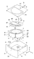
도 1과 도 2는 본 발명 의류처리장치의 일례를 도시한 것이다.
도 3은 드로워, 터브 및 드럼의 결합관계의 일례를 도시한 것이다.
도 4는 본 발명에 구비된 세척부의 일례를 도시한 것이다.
도 5는 본 발명에 구비된 세척 가이더의 일례를 도시한 것이다.
도 6은 본 발명에 구비된 분사부의 일례를 도시한 것이다.Fig. 1 and Fig. 2 show an example of the clothes processing apparatus of the present invention.
Fig. 3 shows an example of the relationship of the drawer, the tub and the drum.
4 shows an example of a washing unit provided in the present invention.
Fig. 5 shows an example of the cleaning guider provided in the present invention.
Fig. 6 shows an example of the jetting portion provided in the present invention.
이하에서는 첨부된 도면을 참고하여 본 발명의 바람직한 실시예를 상세하게 설명한다. 이하에 기술될 장치의 구성이나 제어방법은 본 발명의 실시예를 설명하기 위한 것일 뿐 본 발명의 권리범위를 한정하기 위함은 아니며, 명세서 전반에 걸쳐서 동일하게 사용된 참조번호들은 동일한 구성요소들을 나타낸다.Hereinafter, preferred embodiments of the present invention will be described in detail with reference to the accompanying drawings. It is to be understood that both the foregoing description and the following detailed description are exemplary and explanatory only and are not restrictive of the scope of the invention, .
도 1과 도 2에 도시된 바와 같이, 본 발명 의류처리장치(100)는 캐비닛(2), 상기 캐비닛에서 인출 가능하게 구비되는 드로워(3), 상기 드로워 내부에 구비되어 물이 저장되는 터브(4), 상기 터브 내부에 회전 가능하게 구비되어 의류가 저장되는 드럼(5)을 포함한다.As shown in FIGS. 1 and 2, the
상기 캐비닛(2)은 의류처리장치의 외관을 형성하는 수단으로 구비될 수도 있고, 단순히 상기 드로워(3)를 수용하는 공간으로 구비될 수도 있다. 어느 경우에나 캐비닛(2)의 전방면에는 드로워(3)가 삽입되는 개방면(21)이 구비됨이 바람직하다.The
상기 드로워(3)는 상기 개방면(21)을 통해 캐비닛(2)의 내부로 삽입되는 드로워 바디(31), 상기 드로워 바디(31)의 전방면에 고정되어 상기 개방면(21)을 개폐하는 드로워 패널(33), 상기 드로워 바디(31)의 상부면을 형성하는 드로워 커버(35)를 포함한다.The drawer 3 includes a
상기 드로워 패널(33)은 드로워 바디(31)의 전방면에 고정되기 때문에 상기 드로워 바디(31)를 캐비닛(2)에서 인출하는 핸들의 역할도 수행할 수 있다.Since the
상기 드로워 패널(33)에는 의류처리장치(100)의 작동과 관련된 제어명령을 입력 및 의류처리장치의 작동과 관련된 메시지를 사용자에게 표시하는 컨트롤패널(331)이 구비될 수 있다.The
상기 드로워 바디(31)는 상기 개방면(21)을 통해 캐비닛(2)에 삽입될 수 있고, 상기 터브(4)를 수용하는 공간을 제공할 수 있는 한 어떠한 형상으로도 구비될 수 있는데, 도 1은 내부가 비어있는 육면체 형상의 드로워 바디(31)를 일례로 도시한 것이다.The
상기 드로워 커버(35)에는 드로워 바디(31) 내부를 외부와 연통시키는 제1관통홀(351)과 제2관통홀(353)이 구비된다. 상기 제1관통홀(351)은 의류의 출입을 위해 구비되고, 상기 제2관통홀(353)은 의류의 세탁에 필요한 물을 공급하기 위해 구비되어야 하는데 자세한 설명은 후술한다.The
도 2에 도시된 바와 같이, 상기 터브(4)는 상기 드로워 바디(31) 내부에 위치하여 물이 저장되는 터브 바디(41), 상기 터브 바디(41)의 상부면을 형성하는 터브 커버(43)를 포함한다. 상기 터브 바디(41)는 상부면이 개방된 원통형상으로 구비될 수 있으며, 상기 터브 바디(41) 내부에는 물을 가열하는 히터(411)가 구비될 수 있다.2, the
상기 터브 커버(43)는 상기 터브 바디(41) 내부를 상기 터브 바디의 외부와 연통시키는 투입구(431), 상기 터브 바디(41) 내부로 물을 유입시키는 공급구(433)를 포함할 수 있다.The
상기 투입구(431)는 드로워 커버에 구비된 제1관통홀(351)의 하부에 구비되어야 하고, 상기 공급구(433)는 드로워 커버의 제2관통홀(353)의 하부에 구비됨이 바람직하다.The
상기 투입구(431)는 터브 바디(41) 내부로 의류를 공급하거나 터브 바디(41) 내부의 의류를 터브 바디의 외부로 인출하기 위한 수단으로, 상기 투입구(431)는 도어(45)에 의해 개폐된다.The
도 3에 도시된 바와 같이, 상기 도어(45)는 힌지(453)를 통해 상기 터브 커버(43)에 회전 가능하게 결합되는 프레임(451), 상기 프레임에 구비되는 윈도우(455), 상기 프레임(451)을 상기 터브 커버(43)에 착탈 가능하게 결합시키는 도어 핸들(457)로 구비될 수 있다.3, the
상기 드로워(3)가 캐비닛(2)에서 인출된 경우, 사용자가 터브 바디(41) 내부를 확인할 수 있도록 상기 윈도우(455)는 투명재질로 구비됨이 바람직하다.When the drawer 3 is drawn out from the
한편, 상기 투입구(431)를 통해 상기 터브 바디(41) 내부의 물이 터브 바디(41) 외부로 배출되는 것을 방지하기 위해, 상기 프레임(451)과 상기 터브 커버(43) 중 어느 하나에는 상기 도어(45)가 투입구(431)를 폐쇄한 때 프레임(451)과 투입구(431) 사이의 공간을 밀폐시키는 실링부(459)가 더 구비될 수 있다.In order to prevent the water in the
상술한 구조를 가진 터브(4)는 터브지지부(6)를 통해 드로워 바디(31)에 결합하는데, 상기 터브지지부(6)는 드로워 바디(31)에 구비되는 제1지지부(61), 터브 바디(41)에 구비되는 제2지지부(63), 제1지지부와 제2지지부를 연결하는 연결부(65)로 구비될 수 있다.The
상기 연결부(65)는 제1지지부(61)에 안착되는 제1연결부(651), 제2지지부(63)를 지지하는 제2연결부(653), 상기 제1연결부와 제2연결부를 연결하는 바(bar, 655)로 구비될 수 있다.The
상기 제1연결부(651)는 상기 제1지지부(61) 내부에 안착하되 제1지지부(61) 내부에서 운동할 수 있는 형상으로 구비되고, 상기 제2연결부(653)는 상기 제2지지부(63)를 지지하되 제2지지부(63) 내부에서 운동할 수 있는 형상으로 구비됨이 바람직하다.The
도 2는 제1연결부(651) 및 제2연결부(653)가 구 형상으로 구비된 경우를 일례로 도시한 것이고, 도 3은 각 지지부(61, 63)에 접촉되는 면이 반구 형상으로 구비된 연결부(651, 653)를 일례로 도시한 것이다.FIG. 2 shows an example in which the
한편, 도 2에 도시된 바와 같이, 상기 바(655)는 상기 캐비닛(2)의 바닥면에 대해 직각을 형성하도록 구비(캐비닛의 높이방향 Z에 나란하게 구비, 드로워의 바닥면에 직각을 형성하도록 구비)될 수 있다.2, the
본 발명은 적어도 3개 이상의 터브지지부(6)가 터브 바디(41)를 드로워 바디(31)에 결합시키도록 구비되고, 상기 바(655)가 캐비닛의 바닥면에 대해 직각을 형성하도록 구비되므로, 상기 바(655)가 Z축에 대해 소정각도 경사지게 구비되는 경우에 비해 상기 터브 커버(43)와 상기 드로워 커버(35) 사이의 간격을 넓힐 수 있다.The present invention is characterized in that at least three
따라서, 본 발명에 구비된 상기 터브지지부(6)는 상기 터브 바디(41)가 드로워 바디(31) 내부에서 진동하더라도 상기 터브 커버(43)가 드로워 커버(35)에 충돌할 가능성을 최소화 가능하다.The
한편, 상기 바(655)가 드로워의 바닥면에 대해 직각을 형성하도록 구비되면, 상기 제1지지부(61)와 제2지지부(63) 중 적어도 어느 하나는 드로워 바디(31)에 착탈 가능하게 구비됨이 바람직하다.At least one of the
상기 터브지지부(6)가 적어도 3개 이상 구비되고, 제1지지부(61)와 제2지지부(63) 모두 드로워 바디(31)에서 분리될 수 없도록 구비되면, 상기 터브 바디(41)를 드로워 바디(31)에 고정하는 작업자는 제2지지부(63)가 제1지지부(61)에 간섭되지 않도록 드로워 바디(31)에 터브 바디(41)를 삽입한 뒤 제2지지부(63)가 제1지지부(61)를 통과하는 수직선 상에 위치되도록 터브 바디(41)를 회전시켜야만 제1연결부(651)를 제1지지부(61)에 결합할 수 있다.When at least three
그런데, 터브지지부의 바(655)가 드로워 바닥면에 대해 직각을 형성하도록 구비되는 특징은 터브 바디(41)의 외주면과 드로워 바디(31)의 내주면 사이의 간격(S)을 최소화시켜 의류처리장치(100)의 부피를 최소화할 수 있는 반면 상술한 과정을 통해 진행되는 제1연결부(651)와 제1지지부(61)의 조립성을 악화시킬 수 있다. 이와 같은 단점은 상기 제1지지부(61)가 드로워 바디(31)에 착탈 가능하게 구비됨으로써 해결될 수 있다.The feature that the
상기 터브(4) 내부에 구비되는 드럼(5)은 상부에 개방면(53)이 구비된 원통형상의 드럼 바디(51)로 구비될 수 있다. 상기 개방면(53)은 상기 투입구(431)의 하부에 위치하므로 투입구(431)를 통해 공급되는 의류는 개방면(53)을 통해 드럼 바디(51)로 공급될 것이다.The
한편, 상기 드럼 바디(51)의 바닥면(57)과 원주면(55)에는 드럼 바디(51) 내부를 터브 바디(41)와 연통시키는 다수의 드럼 관통홀(59)이 구비될 수 있다.The
상기 드럼 바디(51)는 구동부에 의해 터브 바디(41) 내부에서 회전하는데, 상기 구동부는 터브 바디(41)의 외부에 위치하되 터브 바디의 바닥면에 고정되는 스테이터(M1), 상기 스테이터가 제공하는 회전자계(rotating field)에 의해 회전하는 로터(M2), 상기 터브 바디(41)의 바닥면을 관통하도록 구비되어 상기 드럼의 바닥면(57)과 로터(M3)를 연결하는 회전축(M3)으로 구비될 수 있다. 이 경우, 상기 회전축(M3)은 터브 바디(41)의 바닥면에 대해 직각을 형성하도록 구비될 수 있다.The
상술한 구조를 가진 의류처리장치(100)는 급수부(7)를 통해 터브(4)에 물을 공급하고, 배수부(8)를 통해 터브(4)에 저장된 물을 캐비닛(2)의 외부로 배출한다.The
도 2에 도시된 바와 같이, 상기 급수부(7)는 터브 커버에 구비된 공급구(433)에 연결된 제1급수관(71), 캐비닛의 외부에 위치한 급수원에 연결된 제2급수관(73), 상기 터브 커버(43)에 고정되어 상기 제1급수관과 제2급수관을 연결하는 연결관(75)으로 구비될 수 있다.2, the water supply unit 7 includes a first
상기 제1급수관(71)은 드로워 커버(35)에 구비된 제2관통홀(353)을 통해 공급구(433)와 연결관(75)을 연결하며, 터브(4)의 진동 시 제1급수관(71)이 연결관(75)에서 분리되는 것을 막기 위해 주름관으로 구비될 수 있다(도 3 참고).The first
또한, 상기 드로워(3)가 캐비닛(2)에서 인출될 때 제2급수관(73)이 연결관(75)에서 분리되는 것을 막기 위해 제2급수관(73) 역시 주름관으로 구비될 수 있다. 상기 제2급수관(73)은 제어부(미도시)의 제어를 받는 급수밸브(77)에 의해 개폐된다.The second
다만, 도 2에 도시된 바와 달리, 상기 급수부(7)는 캐비닛의 외부에 위치한 급수원(미도시)과 상기 터브 커버에 구비된 공급구(433)를 연결하는 하나의 급수관으로 구비될 수 있다. 이 경우, 상기 급수관은 주름관으로 구비됨이 바람직하다.2, the water supply unit 7 may be provided as a single water supply pipe connecting a water supply source (not shown) provided outside the cabinet and a
상기 배수부(8)는 드로워 바디(31)에 고정되는 배수펌프(81), 상기 터브 바디(41) 내부의 물을 배수펌프(81)로 안내하는 제1배수관(83), 상기 배수펌프(81)에서 배출되는 물을 캐비닛(2)의 외부로 안내하는 제2배수관(85)으로 구비될 수 있다. 이 경우 상기 제2배수관(85)은 주름관으로 구비될 수 있다.The drainage unit 8 includes a
상술한 구조를 가진 의류처리장치(100)는 드럼(5)에 의류를 투입하고, 터브(4)에 물과 세제를 공급한 뒤 구동부를 통해 드럼(5)을 회전시킴으로써 의류를 세탁하게 된다.The
상기 드럼(5)의 회전 시 터브(4) 내부에는 수류가 형성되기 때문에 의류의 세탁 중 세제가 용해되면서 발생된 거품이나 의류에서 배출된 오물은 세탁이 완료된 뒤 도어(45)나 드럼(5) 등에 잔류할 가능성이 있다.Since the water is formed in the
세탁이 완료되었음에도 도어(45)의 내측 표면이나 드럼 원주면 등에 거품이나 오물이 잔류하게 되면, 사용자는 의류의 세탁이 완료되지 않은 것으로 착각하거나 의류처리장치(100)의 고장을 의심하게 되는 문제가 발생할 수도 있다.If bubbles or dirt remain on the inner surface of the
이와 같은 문제를 해결하기 위해 본 발명 의류처리장치(100)에는 상기 도어(45)에 잔류하는 이물질(거품이나 오물 등)을 제거하는 세척부(91), 거품의 발생을 억제할 뿐아니라 드럼을 세척하는 분사부(93) 중 적어도 어느 하나를 더 포함할 수 있다.In order to solve such a problem, the
도 4에 도시된 세척부(91)는 드럼(5)의 회전 시 발생하는 원심력을 이용하여 상기 도어(45)를 세척하는 수단이다.The
본 발명에 구비된 드럼(5)은 회전중심을 형성하는 회전축(M3)이 터브 바디의 바닥면에 대해 직각을 형성하므로 드럼(5)의 회전 시 터브(4) 내부의 물은 원심력에 의해 터브 바디(41)의 원주면을 따라 상승한 뒤 터브 커버(43)를 따라 투입구(431) 방향으로 이동한다. 본 실시예에 따른 세척부(91)는 원심력에 의해 터브 커버(43) 방향으로 이동한 물을 도어(45)가 위치된 방향으로 배출시킴으로써 도어(45)를 세척하는 수단이다.The
도 4의 세척부(91)는 상기 터브 커버(43)에서 상기 드럼(5)의 상부면을 향해 돌출되는 차단벽(911), 상기 터브 커버(43)의 가장자리에서 상기 차단벽(911)를 향해 연장되는 가이더(915), 상기 차단벽을 관통하도록 구비되어 상기 가이더(915)를 따라 이동하는 물을 상기 도어(45)가 위치된 방향으로 배출시키는 배출부(913)로 구비될 수 있다.The
상기 차단벽(911)은 상기 투입구(431) 전체를 감싸도록 구비될 수도 있고, 상기 투입구(431)를 단속적으로 감싸도록 구비될 수도 있다. 차단벽이 투입구를 단속적으로 감싼다는 의미는 상기 투입구의 가장자리를 따라 다수의 차단벽 서로 이격되어 배치됨을 의미한다.The blocking
도 4 (b)는 상기 차단벽(911)이 투입구(431) 전체를 감싸도록 구비된 경우를 도시한 것으로, 이 경우 상기 차단벽(911)은 투입구(431)의 가장자리에서 드럼(5)을 향해 돌출되어 구비될 수 있다.4B shows a case in which the blocking
한편, 상기 도어(45)가 터브 커버(43)의 상부면에 회전 가능하게 결합됨으로써 도어(45)의 내측 표면(물에 접촉하는 도어의 일면)이 배출부(913)보다 높은 위치에 있을 경우, 상기 배출부(913)는 상기 도어(45)를 향해 물이 배출되도록 소정각도 경사지게 구비됨이 바람직하다.When the
나아가, 상기 도어(45)에 투명재질로 구비되는 윈도우(455)가 구비될 경우, 사용자는 윈도우(455)를 통해 이물질의 잔류 여부를 확인하게 될 것이므로 상기 배출부(913)는 상기 윈도우(455)로 물이 배출되도록 경사지게 구비될 수도 있다.When the
상기 가이더(915)는 상기 드럼(5)이 시계방향으로 회전할 때 상기 터브 커버(43)의 가장자리로 이동하는 물을 상기 배출부(913)로 안내하는 제1가이더(915a), 상기 드럼(5)이 반시계방향으로 회전할 때 상기 터브 커버(43)의 가장자리로 이동하는 물을 상기 배출부(913)로 안내하는 제2가이더(915b)로 구비될 수 있다.The
상기 배출부(913)가 상기 차단벽(911)을 관통하는 하나의 홀로 구비될 경우, 각 가이더(915a, 915b)는 동일한 배출부(913)로 물을 안내하게 될 것이다. 그러나, 상기 배출부(913)가 상기 차단벽(911)를 관통하도록 구비되는 제1배출부(913a) 및 제2배출부(913b)를 포함하도록 구비될 경우, 상기 제1가이더(915a)는 제1배출부(913a)로 물을 안내하고 상기 제2가이더(915b)는 제2배출부(913b)로 물을 안내하도록 구비될 수 있다.When the
상기 제1가이더(915a)를 따라 이동하는 물의 방향은 상기 제2가이더(915b)를 따라 이동하는 물의 방향과 반대방향이기 때문에 본 발명에 구비된 세척부(91)는 드럼(5)의 회전수가 기 설정된 기준회전수(원심력에 의해 터브 바디 내부의 물이 터브 커버까지 상승하는 회전수) 이상이기만 하면 드럼의 회전방향에 상관없이 도어(45)를 세척할 수 있다.Since the direction of the water moving along the
또한, 상기 제1배출부(913a)에서 배출되는 물의 궤적과 상기 제2배출부(913b)에서 배출되는 물의 궤적이 서로 교차 되도록 각 배출부(913a, 913b)는 소정각도 경사지게 구비될 수도 있는데, 이를 통해 본 발명은 세척부(91)의 세척범위를 확대할 수 있을 것이다.Each of the
상술한 구조를 가진 세척부(91)는 상기 투입구(431)의 가장자리를 따라 다수 개가 배치될 수 있으며, 다수 개의 세척부(91)는 상기 투입구(431)을 감싸도록 배치됨이 바람직하다. 나아가, 다수의 상기 세척부(91) 중 적어도 두 개는 서로 마주보도록 배치될 수 있다. 세척부(91)의 세척력을 높이기 위함이다.A plurality of cleaning
한편, 상기 도어(45)에 잔류하는 이물질은 도 5에 도시된 세척 가이더(456)를 통해 제거될 수도 있다. 상기 세척 가이더(456)는 윈도우(455)의 가장자리에 구비될 수 있다. 드럼의 회전 시 터브 내부의 물은 원심력에 의해 터브의 바닥면에서 프레임(451)의 가장자리로 이동할 뿐만 아니라 프레임(451)의 가장자리 주변을 회전할 수 있는데, 상기 윈도우(455)의 가장자리에 상기 세척 가이더(456)가 구비되어 있으면 프레임(451)의 가장자리를 따라 회전하는 물 중 일부를 윈도우(455)의 중심 방향으로 안내(W1, W2)될 수 있다. 따라서, 본 발명은 상기 세척 가이더(456)를 통해 윈도우에 이물질이 잔류하는 문제를 방지할 수 있다.Meanwhile, foreign matter remaining on the
다만, 세척영역을 최대화하기 위해 상기 세척 가이더(456)는 상기 도어(45)의 대칭선(Q, symmetrical line)을 기준으로 서로 대칭되는 위치에 구비되는 제1세척 가이더(456a) 및 제2세척 가이더(456b)로 구비될 수 있다(도 5 (b) 참고).In order to maximize the cleaning area, the
본 발명은 세척부(91)와 세척 가이더(456) 중 어느 하나만을 포함하도록 구비될 수도 있고, 상기 세척부(91)와 세척 가이더(456)를 모두 포함하도록 구비될 수도 있다.The present invention may include only one of the
도 6은 상기 공급구(433)로 유입되는 물을 상기 드럼(5)에 분사하여 드럼의 내주면을 세척하거나 상기 드럼 내부에 발생된 거품을 제거하는 분사부(93)의 일례를 도시한 것이다.6 shows an example of a
본 실시예에 따른 분사부(93)는 적어도 두 개 이상의 서로 다른 방향으로 물을 분사 가능한 것이 특징으로, 도 6의 분사부(93)는 상기 터브 커버(43)에서 돌출되어 구비되되 상기 공급구(433)를 감싸는 연장부(933), 상기 연장부(933)에 고정되어 상기 공급구(433)와 소정거리 이격된 위치에 고정되는 바디(931), 상기 연장부(933)를 관통하도록 구비되어 상기 연장부(933)로 유입된 물이 배출되는 적어도 두 개 이상의 분사구로 구비될 수 있다.The jetting
도 6의 분사부(93)는 상기 분사구가 제1분사구(935) 제2분사구(937) 및 제3분사구(939)로 구비된 경우를 일례로 도시한 것으로, 상기 각 분사구(935, 937, 939) 사이의 간격은 서로 달리 설정될 수 있다.The jetting
한편, 드럼의 원주면을 세척하기 위해 상기 다수의 분사구(935, 937, 939) 중 적어도 어느 하나는 상기 드럼의 원주면(55)을 향해 물을 분사하도록 구비되고, 다수의 분사구 중 적어도 어느 하나는 드럼 내부에 발생된 거품을 제거할 수 있도록 상기 드럼의 바닥면을 향해 물을 분사하도록 구비될 수 있다.At least one of the plurality of
상기 각 분사구(935, 937, 939)에서 배출되는 물의 압력을 높이기 위해 상기 바디(931)에는 상기 분사구(935, 937, 939)를 향해 상향 경사지게 구비되는 경사면(932)이 더 구비될 수 있다.The
상기 경사면은 상기 바디(931)의 표면에서 제1분사구(935)를 향해 상향 경사지게 구비되는 제1경사면(931a), 상기 바디의 표면에서 제2분사구(937)를 향해 상향 경사지게 구비되는 제2경사면(931b), 상기 바디의 표면에서 상기 제3분사구(939)를 향해 상향 경사진 제3경사면(미도시)으로 구비될 수 있다.The inclined surface includes a first
상기 경사면들(931a, 931b) 때문에 상기 바디(931) 중심에서 각 분사구(935, 937, 939)를 향할수록 물이 이동하는 유로의 단면적은 좁아진다. 따라서, 본 발명에 구비된 분사부(93)는 각 분사구(935, 937, 939)에서 배출되는 물의 압력을 높임으로써 물을 멀리까지 분사할 수 있다.The sectional area of the flow path through which the water moves becomes narrower toward the
한편, 상술한 구조를 가진 상기 분사부(93)는 상기 드럼(5)의 회전중심에서 소정거리 이격되어 구비됨이 바람직하다. 상기 분사부(93)가 드럼의 회전중심과 동일한 위치에 있으면 드럼의 가장자리에는 물을 분사할 수 있지만 분사부(93)의 하부에 위치된 드럼의 회전중심에는 물을 분사하기 어렵다.Meanwhile, it is preferable that the jetting
상기 바디(931)에 관통홀을 형성하여 드럼의 회전중심에 물을 공급할 수도 있지만, 바디(931)에 관통홀을 구비시키면 각 분사구(935, 937, 939)를 통해 배출되는 물의 압력이 저하되는 문제가 발생할 수 있다.However, if a through hole is provided in the
그런데, 상기 분사부(93)가 드럼의 회전중심을 통과하는 직선상에 위치하지 않도록 구비되면 상기 분사부(93)에서 분사되는 물의 압력저하 없이도 드럼의 전영역에 물을 공급 가능하다.However, if the jetting
본 발명은 다양한 형태로 변형되어 실시될 수 있을 것인바 상술한 실시예에 그 권리범위가 한정되지 않는다. 따라서 변형된 실시예가 본 발명 특허청구범위의 구성요소를 포함하고 있다면 본 발명의 권리범위에 속하는 것으로 보아야 할 것이다.The present invention may be embodied in various forms without departing from the scope of the invention. Accordingly, it is intended that the present invention cover the modifications and variations of this invention provided they come within the scope of the appended claims and their equivalents.
100: 의류처리장치
2: 캐비닛
21: 개방면
3: 드로워
31: 드로워 바디
33: 드로워 패널
35: 드로워 커버
351: 제1관통홀
353: 제2관통홀
4: 터브
41: 터브 바디
43: 터브 커버
431: 투입구
433: 공급구
45: 도어
451: 프레임
453: 힌지
455: 윈도우
457: 도어 핸들
459: 실링부
5: 드럼
51: 드럼 바디
53: 개방면
6: 터브지지부
61: 제1지지부
63: 제2지지부
65: 연결부
7: 급수부
8: 배수부
91: 세척부
911: 차단벽
913: 배출구
913a: 제1배출부
913b: 제2배출부
915: 가이더
915a: 제1가이더
915b: 제2가이더100: garment disposal apparatus 2: cabinet 21: opening face
3: drawer 31: drawer body 33: drawer panel
35: Drawer cover 351: First through hole 353: Second through hole
4: tub 41: tub body 43: tub cover
431: Inlet port 433: Feed port 45: Door
451: Frame 453: Hinge 455: Window
457: Door handle 459: Sealing part 5: Drum
51: drum body 53: opening 6: tub support
61: first support part 63: second support part 65:
7: water supply part 8: drainage part 91: cleaning part
911: blocking wall 913:
913b: second discharge portion 915: guider 915a: first guider
915b: second guider
Claims (15)
상기 터브 바디의 상부면을 형성하는 터브 커버;
상기 터브 커버를 관통하도록 구비되는 투입구;
상기 터브 커버에 구비되어 상기 터브 바디로 물을 공급하는 공급구;
상기 터브 바디 내부에 회전 가능하게 구비되어 의류가 수용되며, 상기 투입구에 연통하는 개방면을 포함하는 드럼;
상기 투입구를 개폐하는 도어;
상기 공급구로 유입되는 물을 상기 드럼에 분사하는 분사부;를 포함하고,
상기 분사부는 적어도 두 개 이상의 서로 다른 방향으로 물을 분사하는 것을 특징으로 하는 의류처리장치.A tub body in which water is stored;
A tub cover forming an upper surface of the tub body;
A discharge port provided to penetrate through the tub cover;
A supply port provided on the tub cover for supplying water to the tub body;
A drum rotatably provided in the tub body to receive clothes therein and having an opening communicating with the charging port;
A door that opens and closes the charging port;
And a jetting part for jetting water, which flows into the supply port, onto the drum,
Wherein the jetting unit ejects water in at least two or more different directions.
상기 분사부는
상기 공급구를 감싸도록 구비되는 연장부;
상기 연장부에 고정되어 상기 공급구와 소정거리 이격된 위치에 고정되는 바디;
상기 연장부를 관통하도록 구비되어 상기 연장부로 유입된 물이 배출되는 적어도 두 개 이상의 분사구;를 포함하는 것을 특징으로 하는 의류처리장치.The method according to claim 1,
The injector
An extension part provided to surround the supply port;
A body fixed to the extended portion and fixed at a position spaced apart from the supply port by a predetermined distance;
And at least two jetting openings penetrating the extended portion and discharging water introduced into the extended portion.
상기 바디의 표면에서 상기 분사구를 향해 상향 경사지게 구비되는 경사면;을 더 포함하는 것을 특징으로 하는 의류처리장치.3. The method of claim 2,
And an inclined surface inclined upwards from the surface of the body toward the jetting port.
상기 드럼을 회전시키며, 상기 터브 바디의 바닥면에 대해 직각을 형성하도록 구비되는 회전축;
상기 드럼의 회전 시 발생하는 원심력에 의해 상기 터브 커버 방향으로 이동하는 물 중 적어도 일부를 상기 도어에 분사하는 세척부;를 더 포함하는 것을 특징으로 하는 의류처리장치.The method according to claim 1,
A rotating shaft which rotates the drum and is formed to form a right angle with respect to a bottom surface of the tub body;
And a washing unit for spraying at least a part of water moving in the direction of the tub cover to the door by a centrifugal force generated when the drum rotates.
상기 분사부는 상기 드럼의 회전중심에서 소정거리 이격되어 구비되는 것을 특징으로 하는 의류처리장치.5. The method according to any one of claims 1 to 4,
Wherein the jetting unit is spaced apart from the rotation center of the drum by a predetermined distance.
상기 세척부는
상기 터브 커버의 가장자리에서 상기 투입구를 향해 연장되는 가이더;
상기 가이더에 의해 공급되는 물을 상기 도어가 위치된 방향으로 배출시키는 배출부;를 포함하는 것을 특징으로 하는 의류처리장치.6. The method of claim 5,
The washing unit
A guider extending from an edge of the tub cover toward the inlet port;
And a discharge unit for discharging the water supplied by the guider in a direction in which the door is located.
상기 세척부는 상기 터브 커버에서 상기 드럼의 상부면을 향해 돌출되되 상기 투입구의 가장자리를 감싸는 차단벽;을 더 포함하고,
상기 배출부는 상기 차단벽을 관통하도록 구비되는 것을 특징으로 하는 의류처리장치.The method according to claim 6,
The washing unit may further include a blocking wall protruding from the tub cover toward the upper surface of the drum and surrounding the edge of the inlet,
Wherein the discharge portion is provided so as to pass through the blocking wall.
상기 도어는 상기 투입구의 상부에 위치하며,
상기 배출부는 상기 도어를 향해 물이 배출되도록 경사지게 구비되는 것을 특징으로 하는 의류처리장치.8. The method of claim 7,
The door is located at the top of the inlet,
Wherein the discharge portion is inclined so as to discharge water toward the door.
상기 도어는 상기 터브 커버에 회전 가능하게 결합된 프레임 및 상기 터브 바디의 외부에서 상기 터브 바디의 내부를 관찰할 수 있도록 상기 프레임에 구비되는 윈도우를 포함하고,
상기 배출부는 상기 윈도우를 향해 물이 배출되도록 경사지게 구비되는 것을 특징으로 하는 의류처리장치.8. The method of claim 7,
Wherein the door includes a frame rotatably coupled to the tub cover and a window provided on the frame so as to observe the inside of the tub body from the outside of the tub body,
Wherein the discharge unit is inclined to discharge water toward the window.
상기 가이더는
상기 드럼이 시계방향으로 회전할 때 상기 터브 커버로 이동하는 물을 상기 배출부로 안내하는 제1가이더;
상기 드럼이 반시계방향으로 회전할 때 상기 터브 커버로 이동하는 물을 상기 배출부로 안내하는 제2가이더;를 포함하는 것을 특징으로 하는 의류처리장치.The method according to claim 6,
The guider
A first guider for guiding water moving to the tub cover to the discharge unit when the drum rotates in a clockwise direction;
And a second guider for guiding water moving to the tub cover to the discharge unit when the drum rotates in a counterclockwise direction.
상기 배출부는
상기 제1가이더를 통해 공급되는 물을 상기 도어에 배출하는 제1배출부;
상기 제2가이더를 통해 공급되는 물을 상기 도어에 배출하는 제2배출부;를 포함하는 것을 특징으로 하는 의류처리장치.11. The method of claim 10,
The outlet
A first discharger for discharging water supplied through the first guider to the door;
And a second discharge unit for discharging water supplied through the second guider to the door.
상기 제1배출부에서 배출되는 물의 궤적과 상기 제2배출부에서 배출되는 물의 궤적이 서로 교차하도록 상기 제1배출부와 상기 제2배출부는 경사지게 구비되는 것을 특징으로 하는 의류처리장치.12. The method of claim 11,
Wherein the first discharge portion and the second discharge portion are inclined so that a trajectory of water discharged from the first discharge portion and a trajectory of water discharged from the second discharge portion cross each other.
상기 세척부는 적어도 2개 이상으로 구비되고, 다수의 상기 세척부 중 적어도 2개는 서로 마주보도록 배치되는 것을 특징으로 하는 의류처리장치.6. The method of claim 5,
Wherein at least two washing units are provided, and at least two of the plurality of washing units are arranged to face each other.
캐비닛;
상기 캐비닛에서 인출 가능하게 구비되며, 상기 터브 바디가 지지되는 드로워;를 더 포함하는 것을 특징으로 하는 의류처리장치.The method according to claim 1,
cabinet;
Further comprising: a drawer provided so as to be able to be drawn out from the cabinet and to which the tub body is supported.
상기 드럼을 회전시키며, 상기 터브 바디의 바닥면에 대해 직각을 형성하도록 구비되는 회전축;을 더 포함하고,
상기 도어는 상기 터브 커버에 회전 가능하게 결합된 프레임; 상기 터브 바디의 외부에서 상기 터브 바디의 내부를 관찰할 수 있도록 상기 프레임에 구비되는 윈도우; 및 상기 드럼의 회전 시 발생하는 원심력에 의해 상기 프레임의 가장자리로 이동된 물 중 적어도 일부를 상기 윈도우로 안내하는 세척 가이더;를 포함하는 것을 특징으로 하는 의류처리장치.The method according to claim 1,
And a rotating shaft rotatably supporting the drum to form a right angle with respect to a bottom surface of the tub body,
The door includes a frame rotatably coupled to the tub cover. A window provided on the frame so as to observe the inside of the tub body outside the tub body; And a washing guider for guiding at least a part of the water moved to the edge of the frame to the window by a centrifugal force generated when the drum rotates.
Priority Applications (15)
| Application Number | Priority Date | Filing Date | Title |
|---|---|---|---|
| KR1020150092773A KR102402082B1 (en) | 2015-06-30 | 2015-06-30 | Laundry Treating Apparatus |
| TW105118992A TWI626352B (en) | 2015-06-30 | 2016-06-16 | Laundry treatment apparatus |
| EP16176913.8A EP3112521B1 (en) | 2015-06-30 | 2016-06-29 | Laundry treatment apparatus |
| TR2019/00170T TR201900170T4 (en) | 2015-06-30 | 2016-06-29 | Laundry Processing Apparatus |
| CN201610507593.XA CN106319821B (en) | 2015-06-30 | 2016-06-30 | Device for clothing processing |
| JP2017510371A JP6980522B2 (en) | 2015-06-30 | 2016-06-30 | Clothes processing equipment |
| BR112017003082-9A BR112017003082B1 (en) | 2015-06-30 | 2016-06-30 | APPARATUS FOR CLOTHING TREATMENT |
| CA2956309A CA2956309C (en) | 2015-06-30 | 2016-06-30 | Laundry treatment apparatus |
| MX2017001967A MX2017001967A (en) | 2015-06-30 | 2016-06-30 | Laundry treatment apparatus. |
| AU2016285184A AU2016285184B2 (en) | 2015-06-30 | 2016-06-30 | Laundry treatment apparatus |
| US15/197,815 US10487436B2 (en) | 2015-06-30 | 2016-06-30 | Laundry treatment apparatus |
| PCT/KR2016/007025 WO2017003213A1 (en) | 2015-06-30 | 2016-06-30 | Laundry treatment apparatus |
| RU2017107191A RU2664368C1 (en) | 2015-06-30 | 2016-06-30 | Linen treatment device |
| ZA2017/00610A ZA201700610B (en) | 2015-06-30 | 2017-01-25 | Laundry treatment apparatus |
| US16/694,667 US11131052B2 (en) | 2015-06-30 | 2019-11-25 | Laundry treatment apparatus |
Applications Claiming Priority (1)
| Application Number | Priority Date | Filing Date | Title |
|---|---|---|---|
| KR1020150092773A KR102402082B1 (en) | 2015-06-30 | 2015-06-30 | Laundry Treating Apparatus |
Publications (2)
| Publication Number | Publication Date |
|---|---|
| KR20170002880A true KR20170002880A (en) | 2017-01-09 |
| KR102402082B1 KR102402082B1 (en) | 2022-05-26 |
Family
ID=56296599
Family Applications (1)
| Application Number | Title | Priority Date | Filing Date |
|---|---|---|---|
| KR1020150092773A KR102402082B1 (en) | 2015-06-30 | 2015-06-30 | Laundry Treating Apparatus |
Country Status (14)
| Country | Link |
|---|---|
| US (2) | US10487436B2 (en) |
| EP (1) | EP3112521B1 (en) |
| JP (1) | JP6980522B2 (en) |
| KR (1) | KR102402082B1 (en) |
| CN (1) | CN106319821B (en) |
| AU (1) | AU2016285184B2 (en) |
| BR (1) | BR112017003082B1 (en) |
| CA (1) | CA2956309C (en) |
| MX (1) | MX2017001967A (en) |
| RU (1) | RU2664368C1 (en) |
| TR (1) | TR201900170T4 (en) |
| TW (1) | TWI626352B (en) |
| WO (1) | WO2017003213A1 (en) |
| ZA (1) | ZA201700610B (en) |
Families Citing this family (4)
| Publication number | Priority date | Publication date | Assignee | Title |
|---|---|---|---|---|
| KR102402082B1 (en) * | 2015-06-30 | 2022-05-26 | 엘지전자 주식회사 | Laundry Treating Apparatus |
| CN107366136B (en) * | 2017-07-21 | 2022-03-18 | 合肥海尔洗衣机有限公司 | Washing machine outer barrel cover and washing machine |
| CN108315908A (en) * | 2018-02-02 | 2018-07-24 | 绍兴锦晨生物科技有限公司 | A kind of textile cloth cleaning device |
| KR102604561B1 (en) * | 2018-02-23 | 2023-11-22 | 엘지전자 주식회사 | Fabric dryer |
Citations (4)
| Publication number | Priority date | Publication date | Assignee | Title |
|---|---|---|---|---|
| JP2007202638A (en) * | 2006-01-31 | 2007-08-16 | Sanyo Electric Co Ltd | Drum-type washing machine |
| JP2009072643A (en) * | 1998-08-18 | 2009-04-09 | Lg Electronics Inc | Penetration type washing machine, control method thereof, and tub cover for penetration type washing machine |
| JP2010268843A (en) * | 2009-05-19 | 2010-12-02 | Toshiba Corp | Spin dryer washer |
| KR20110130664A (en) * | 2010-05-28 | 2011-12-06 | 엘지전자 주식회사 | Laundry machine |
Family Cites Families (30)
| Publication number | Priority date | Publication date | Assignee | Title |
|---|---|---|---|---|
| US2254003A (en) * | 1940-02-10 | 1941-08-26 | Marco Louis De | Combined washing and rinsing machine |
| TW293854B (en) * | 1993-12-27 | 1996-12-21 | Toshiba Co Ltd | |
| KR20020057120A (en) * | 2000-12-30 | 2002-07-11 | 구자홍 | A shower apparatus for washing machine |
| KR100403029B1 (en) * | 2001-09-28 | 2003-10-23 | 삼성전자주식회사 | Drum Washing Machine |
| KR20040003363A (en) | 2002-07-02 | 2004-01-13 | 엘지전자 주식회사 | Drain part structure of washing machine |
| KR100720574B1 (en) * | 2003-10-17 | 2007-05-22 | 엘지전자 주식회사 | washing machine |
| KR101022225B1 (en) * | 2003-11-18 | 2011-03-17 | 삼성전자주식회사 | Drum Type Washing Machine |
| US7918244B2 (en) * | 2005-05-02 | 2011-04-05 | Massachusetts Institute Of Technology | Microfluidic bubble logic devices |
| KR20070050583A (en) * | 2005-11-11 | 2007-05-16 | 엘지전자 주식회사 | Drum-type washer and tub cleaning method of the same |
| DE102007002184B4 (en) * | 2007-01-15 | 2018-03-15 | BSH Hausgeräte GmbH | Method for washing items of laundry in a program-controlled domestic appliance, and such household appliance |
| JP2008295941A (en) * | 2007-06-04 | 2008-12-11 | Hitachi Appliances Inc | Washing machine |
| KR101466337B1 (en) * | 2008-07-04 | 2014-11-28 | 삼성전자 주식회사 | Washing Machine |
| US9010160B2 (en) * | 2008-09-12 | 2015-04-21 | Whirlpool Corporation | Apparatus for deflecting a spray of wash liquid to a desired location in a cleaning appliance |
| JP2011035190A (en) * | 2009-08-03 | 2011-02-17 | Ricoh Co Ltd | Multi-beam laser light-intensity control circuit, and optical scanning apparatus including the same |
| WO2011053091A2 (en) * | 2009-11-02 | 2011-05-05 | Lg Electronics Inc. | Washing machine |
| KR101647723B1 (en) * | 2009-12-03 | 2016-08-11 | 엘지전자 주식회사 | A control method for Washing machine |
| CN102115970B (en) | 2010-01-05 | 2015-04-08 | 海尔集团公司 | High-pressure spraying device for flushing outer wall of inner barrel of washing machine and method for flushing outer wall of inner barrel |
| US10081898B2 (en) * | 2010-04-30 | 2018-09-25 | Lg Electronics Inc. | Laundry apparatus |
| CN103492628B (en) * | 2011-04-19 | 2016-03-09 | 日立空调·家用电器株式会社 | Washing machine |
| JP5608603B2 (en) * | 2011-04-19 | 2014-10-15 | 日立アプライアンス株式会社 | Washing machine |
| WO2012144264A1 (en) * | 2011-04-19 | 2012-10-26 | 日立アプライアンス株式会社 | Drum-type washing machine |
| EP2705187B1 (en) * | 2011-05-02 | 2016-02-24 | Indesit Company S.p.A. | Appliance for treating textile items and auxiliary washing device |
| WO2013091288A1 (en) * | 2011-12-19 | 2013-06-27 | 海尔集团公司 | Device and method for cleaning observation window and window spacer sealing ring, and washing machine applying the same |
| US9115461B2 (en) * | 2011-12-21 | 2015-08-25 | Whirlpool Corporation | Door wash aid dispenser for a laundry treating appliance |
| CN203212860U (en) * | 2013-04-08 | 2013-09-25 | 松下电器产业株式会社 | Washing machine |
| KR102155003B1 (en) * | 2013-10-24 | 2020-09-11 | 엘지전자 주식회사 | Washing Machine |
| JP2015085080A (en) * | 2013-11-01 | 2015-05-07 | パナソニックIpマネジメント株式会社 | Washing machine |
| CN203960595U (en) * | 2014-05-16 | 2014-11-26 | Tcl家用电器(合肥)有限公司 | Water outlet and adopt the washing machine of this Water outlet |
| KR102255385B1 (en) * | 2014-05-30 | 2021-05-25 | 엘지전자 주식회사 | Laundry Treating Apparatus |
| KR102402082B1 (en) * | 2015-06-30 | 2022-05-26 | 엘지전자 주식회사 | Laundry Treating Apparatus |
-
2015
- 2015-06-30 KR KR1020150092773A patent/KR102402082B1/en active IP Right Grant
-
2016
- 2016-06-16 TW TW105118992A patent/TWI626352B/en active
- 2016-06-29 TR TR2019/00170T patent/TR201900170T4/en unknown
- 2016-06-29 EP EP16176913.8A patent/EP3112521B1/en active Active
- 2016-06-30 JP JP2017510371A patent/JP6980522B2/en active Active
- 2016-06-30 CA CA2956309A patent/CA2956309C/en active Active
- 2016-06-30 CN CN201610507593.XA patent/CN106319821B/en active Active
- 2016-06-30 US US15/197,815 patent/US10487436B2/en active Active
- 2016-06-30 WO PCT/KR2016/007025 patent/WO2017003213A1/en active Application Filing
- 2016-06-30 MX MX2017001967A patent/MX2017001967A/en unknown
- 2016-06-30 BR BR112017003082-9A patent/BR112017003082B1/en not_active IP Right Cessation
- 2016-06-30 RU RU2017107191A patent/RU2664368C1/en active
- 2016-06-30 AU AU2016285184A patent/AU2016285184B2/en active Active
-
2017
- 2017-01-25 ZA ZA2017/00610A patent/ZA201700610B/en unknown
-
2019
- 2019-11-25 US US16/694,667 patent/US11131052B2/en active Active
Patent Citations (4)
| Publication number | Priority date | Publication date | Assignee | Title |
|---|---|---|---|---|
| JP2009072643A (en) * | 1998-08-18 | 2009-04-09 | Lg Electronics Inc | Penetration type washing machine, control method thereof, and tub cover for penetration type washing machine |
| JP2007202638A (en) * | 2006-01-31 | 2007-08-16 | Sanyo Electric Co Ltd | Drum-type washing machine |
| JP2010268843A (en) * | 2009-05-19 | 2010-12-02 | Toshiba Corp | Spin dryer washer |
| KR20110130664A (en) * | 2010-05-28 | 2011-12-06 | 엘지전자 주식회사 | Laundry machine |
Also Published As
| Publication number | Publication date |
|---|---|
| BR112017003082A2 (en) | 2017-12-05 |
| JP2018518993A (en) | 2018-07-19 |
| JP6980522B2 (en) | 2021-12-15 |
| CA2956309A1 (en) | 2017-01-05 |
| TW201700824A (en) | 2017-01-01 |
| WO2017003213A1 (en) | 2017-01-05 |
| CA2956309C (en) | 2019-09-24 |
| MX2017001967A (en) | 2017-05-04 |
| US10487436B2 (en) | 2019-11-26 |
| EP3112521B1 (en) | 2019-01-02 |
| BR112017003082B1 (en) | 2022-09-20 |
| US20170002497A1 (en) | 2017-01-05 |
| RU2664368C1 (en) | 2018-08-16 |
| US11131052B2 (en) | 2021-09-28 |
| TR201900170T4 (en) | 2019-02-21 |
| AU2016285184B2 (en) | 2018-02-22 |
| KR102402082B1 (en) | 2022-05-26 |
| US20200087832A1 (en) | 2020-03-19 |
| TWI626352B (en) | 2018-06-11 |
| AU2016285184A1 (en) | 2017-02-16 |
| EP3112521A1 (en) | 2017-01-04 |
| ZA201700610B (en) | 2019-06-26 |
| CN106319821A (en) | 2017-01-11 |
| CN106319821B (en) | 2019-05-28 |
Similar Documents
| Publication | Publication Date | Title |
|---|---|---|
| KR102421649B1 (en) | Laundry Treating Apparatus | |
| WO2016136154A1 (en) | Washing machine | |
| KR20140046181A (en) | Laundry treating apparatus | |
| KR102557626B1 (en) | Laundry Treating Apparatus | |
| KR20170002880A (en) | Laundry Treating Apparatus | |
| KR20170002881A (en) | Laundry Treating Apparatus | |
| KR20150047372A (en) | Washing Machine | |
| JP6936143B2 (en) | Clothes processing equipment | |
| KR20170086795A (en) | Laundry Treating Apparatus and Control Method for the same | |
| KR20170028127A (en) | Control Method for Laundry Treating Apparatus | |
| KR20210027019A (en) | Detergent supply device and laundry treating apparatus including the same | |
| KR20170135114A (en) | Laundry Treating Apparatus and Control Method thereof | |
| KR20170032126A (en) | Control Method for Laundry Treating Apparatus | |
| KR20180045178A (en) | Laundry Treating Apparatus | |
| KR20130010363A (en) | A washing machine and a methoed for jetting washing water of the washing machine |
Legal Events
| Date | Code | Title | Description |
|---|---|---|---|
| A201 | Request for examination | ||
| E902 | Notification of reason for refusal | ||
| E701 | Decision to grant or registration of patent right |