KR20170002614A - Generation of drive values for a display - Google Patents
Generation of drive values for a displayInfo
- Publication number
- KR20170002614A KR20170002614A KR1020167034551A KR20167034551A KR20170002614A KR 20170002614 A KR20170002614 A KR 20170002614A KR 1020167034551 A KR1020167034551 A KR 1020167034551A KR 20167034551 A KR20167034551 A KR 20167034551A KR 20170002614 A KR20170002614 A KR 20170002614A
- Authority
- KR
- South Korea
- Prior art keywords
- sub
- pixel
- pixels
- values
- value
- Prior art date
Links
Images


Classifications
-
- H—ELECTRICITY
- H04—ELECTRIC COMMUNICATION TECHNIQUE
- H04N—PICTORIAL COMMUNICATION, e.g. TELEVISION
- H04N13/00—Stereoscopic video systems; Multi-view video systems; Details thereof
- H04N13/30—Image reproducers
- H04N13/398—Synchronisation thereof; Control thereof
-
- G—PHYSICS
- G09—EDUCATION; CRYPTOGRAPHY; DISPLAY; ADVERTISING; SEALS
- G09G—ARRANGEMENTS OR CIRCUITS FOR CONTROL OF INDICATING DEVICES USING STATIC MEANS TO PRESENT VARIABLE INFORMATION
- G09G3/00—Control arrangements or circuits, of interest only in connection with visual indicators other than cathode-ray tubes
- G09G3/001—Control arrangements or circuits, of interest only in connection with visual indicators other than cathode-ray tubes using specific devices not provided for in groups G09G3/02 - G09G3/36, e.g. using an intermediate record carrier such as a film slide; Projection systems; Display of non-alphanumerical information, solely or in combination with alphanumerical information, e.g. digital display on projected diapositive as background
- G09G3/003—Control arrangements or circuits, of interest only in connection with visual indicators other than cathode-ray tubes using specific devices not provided for in groups G09G3/02 - G09G3/36, e.g. using an intermediate record carrier such as a film slide; Projection systems; Display of non-alphanumerical information, solely or in combination with alphanumerical information, e.g. digital display on projected diapositive as background to produce spatial visual effects
-
- H04N13/0404—
-
- H—ELECTRICITY
- H04—ELECTRIC COMMUNICATION TECHNIQUE
- H04N—PICTORIAL COMMUNICATION, e.g. TELEVISION
- H04N13/00—Stereoscopic video systems; Multi-view video systems; Details thereof
- H04N13/30—Image reproducers
- H04N13/302—Image reproducers for viewing without the aid of special glasses, i.e. using autostereoscopic displays
- H04N13/305—Image reproducers for viewing without the aid of special glasses, i.e. using autostereoscopic displays using lenticular lenses, e.g. arrangements of cylindrical lenses
-
- H—ELECTRICITY
- H04—ELECTRIC COMMUNICATION TECHNIQUE
- H04N—PICTORIAL COMMUNICATION, e.g. TELEVISION
- H04N13/00—Stereoscopic video systems; Multi-view video systems; Details thereof
- H04N13/30—Image reproducers
- H04N13/302—Image reproducers for viewing without the aid of special glasses, i.e. using autostereoscopic displays
- H04N13/31—Image reproducers for viewing without the aid of special glasses, i.e. using autostereoscopic displays using parallax barriers
-
- H—ELECTRICITY
- H04—ELECTRIC COMMUNICATION TECHNIQUE
- H04N—PICTORIAL COMMUNICATION, e.g. TELEVISION
- H04N13/00—Stereoscopic video systems; Multi-view video systems; Details thereof
- H04N13/30—Image reproducers
- H04N13/302—Image reproducers for viewing without the aid of special glasses, i.e. using autostereoscopic displays
- H04N13/317—Image reproducers for viewing without the aid of special glasses, i.e. using autostereoscopic displays using slanted parallax optics
-
- H—ELECTRICITY
- H04—ELECTRIC COMMUNICATION TECHNIQUE
- H04N—PICTORIAL COMMUNICATION, e.g. TELEVISION
- H04N13/00—Stereoscopic video systems; Multi-view video systems; Details thereof
- H04N13/30—Image reproducers
- H04N13/302—Image reproducers for viewing without the aid of special glasses, i.e. using autostereoscopic displays
- H04N13/32—Image reproducers for viewing without the aid of special glasses, i.e. using autostereoscopic displays using arrays of controllable light sources; using moving apertures or moving light sources
-
- H—ELECTRICITY
- H04—ELECTRIC COMMUNICATION TECHNIQUE
- H04N—PICTORIAL COMMUNICATION, e.g. TELEVISION
- H04N13/00—Stereoscopic video systems; Multi-view video systems; Details thereof
- H04N13/30—Image reproducers
- H04N13/324—Colour aspects
-
- G—PHYSICS
- G09—EDUCATION; CRYPTOGRAPHY; DISPLAY; ADVERTISING; SEALS
- G09G—ARRANGEMENTS OR CIRCUITS FOR CONTROL OF INDICATING DEVICES USING STATIC MEANS TO PRESENT VARIABLE INFORMATION
- G09G2300/00—Aspects of the constitution of display devices
- G09G2300/04—Structural and physical details of display devices
- G09G2300/0439—Pixel structures
- G09G2300/0452—Details of colour pixel setup, e.g. pixel composed of a red, a blue and two green components
-
- G—PHYSICS
- G09—EDUCATION; CRYPTOGRAPHY; DISPLAY; ADVERTISING; SEALS
- G09G—ARRANGEMENTS OR CIRCUITS FOR CONTROL OF INDICATING DEVICES USING STATIC MEANS TO PRESENT VARIABLE INFORMATION
- G09G2320/00—Control of display operating conditions
- G09G2320/02—Improving the quality of display appearance
- G09G2320/0209—Crosstalk reduction, i.e. to reduce direct or indirect influences of signals directed to a certain pixel of the displayed image on other pixels of said image, inclusive of influences affecting pixels in different frames or fields or sub-images which constitute a same image, e.g. left and right images of a stereoscopic display
Abstract
장치는 무안경 입체영상 디스플레이의 서브-픽셀들에 대한 서브-픽셀 구동 값들을 생성하도록 구성된다. 상기 디스플레이는 서브-픽셀들을 구비한 디스플레이 패널(503)을 포함하고; 디스플레이 패널(503)에 오버레이된 렌티큘러 스크린과 같은 뷰 형성 광학 소자(509)를 더 포함한다. 상기 장치는 제공될 적어도 하나의 이미지의 픽셀들에 대한 광 출력 값들을 수신하기 위한 수신기(903) 포함한다. 구동기(905)는 서브-픽셀 구동 값들을 생성한다. 구체적으로 이것은, 제 1 서브-픽셀이 일부인 픽셀에 대한 광 출력 값, 적어도 하나의 다른 서브-픽셀의 서브-픽셀 값, 및 무안경 입체영상 디스플레이의 서브-픽셀들에 대한 서브-픽셀 크로스-토크 특징들을 반영하는 크로스-토크 패턴에 응답하여, 제 1 서브-픽셀에 대한 제 1 구동 값을 생성한다. 또한, 서브-픽셀 구동 값들은 극단의 구동 값들쪽으로, 즉 완전히-온 또는 완전히-오프 값들쪽으로 바이어스된다. The apparatus is configured to generate sub-pixel drive values for sub-pixels of a spectacles stereoscopic image display. The display comprises a display panel (503) with sub-pixels; And a view forming optical element 509 such as a lenticular screen overlaid on the display panel 503. The apparatus includes a receiver 903 for receiving light output values for pixels of at least one image to be provided. The driver 905 generates sub-pixel drive values. Specifically, this means that the light output value for a pixel that is part of the first sub-pixel, the sub-pixel value of at least one other sub-pixel, and the sub-pixel cross- In response to the cross-talk pattern reflecting features, a first drive value for the first sub-pixel is generated. In addition, the sub-pixel drive values are biased toward extreme drive values, i.e., toward fully-on or fully-off values.

Description
본 발명은 무안경 입체영상 디스플레이의 서브-픽셀들에 대한 구동 값들을 생성하는 것에 관한 것이고, 특히 직조 이미지(weaved image)에 기초한 구동 값들의 생성에 관한 것이지만, 이에 국한된 것은 아니다.The present invention relates to generating driving values for sub-pixels in a spectacles stereoscopic display, and more particularly but not exclusively, to generating drive values based on a weaved image.
3D 디스플레이들이 점점 더 관심을 받고 있고, 뷰어에게 3D 인식을 제공하는 방법에 있어서 상당한 연구가 이루어지고 있다. 3D 디스플레이들은 뷰어의 두 눈에 관찰되고 있는 장면의 상이한 뷰들을 제공함으로써 시청 경험에 대한 제 3 차원을 추가한다. 이것은 디스플레이되는 두 개의 뷰들을 분리하기 위해 사용자에게 안경을 착용하게 함으로써 달성될 수 있다. 그러나, 이것은 사용자에게 비교적 불편하므로, 상이한 뷰들을 직접 생성하여 이들을 사용자의 두눈들에 투사하는 무안경 입체영상 디스플레이들을 이용하는 것이 많은 시나리오들에서 바람직하다. 사실, 얼마 동안, 여러 회사들이 3D 이미지를 렌더링하기에 적합한 무안경 입체영상 디스플레이들을 활발히 개발하고 있다. 무안경 입체영상 디바이스들은 특수 헤드기어 및/또는 안경 없이도 뷰어들에게 3D 인상을 제공할 수 있다.3D displays are getting more and more interesting, and considerable research has been done on how to provide 3D perception to viewers. 3D displays add a third dimension to the viewing experience by providing different views of the scene being observed in the viewer's eyes. This can be accomplished by having the user wear eyeglasses to separate the two views being displayed. However, this is relatively uncomfortable to the user, so it is desirable in many scenarios to use non-eyeglass stereoscopic displays that directly create different views and project them onto the user's eyes. In fact, for some time, several companies are actively developing non-eyeglass stereoscopic displays suitable for rendering 3D images. Non-spectacle stereoscopic devices can provide 3D impression to viewers without special headgear and / or glasses.
무안경 입체영상 디스플레이들은 일반적으로 상이한 시야각들에 대해 상이한 뷰들을 제공한다. 이러한 방식으로, 제 1 이미지가 뷰어의 왼쪽 눈에 대해 생성될 수 있고 제 2 이미지가 뷰어의 오른쪽 눈에 대해 생성될 수 있다. 적절한 이미지들, 즉 각각 왼쪽 눈 및 오른쪽 눈의 관찰하는 지점에서의 적절한 이미지들을 디스플레이함으로써, 뷰어에게 3D 인상을 전달하는 것이 가능하다. The non-eyeglass stereoscopic displays typically provide different views for different viewing angles. In this way, a first image can be created for the left eye of the viewer and a second image can be created for the right eye of the viewer. It is possible to convey the 3D impression to the viewer by displaying the appropriate images, i.e. the appropriate images at the point of observation of the left eye and the right eye, respectively.
무안경 입체영상 디스플레이들은, 뷰들을 분리하고 이들을 상이한 방향들로 전송하여 뷰들이 사용자의 눈에 개별적으로 도달하도록 렌티큘러 렌즈들 또는 배리어 마스크들과 같은 수단을 이용하는 경향이 있다. 입체영상 디스플레이들의 경우에는 두 개의 뷰들이 필요하지만, 대부분의 무안경 입체영상 디스플레이들은 통상적으로 더 많은 뷰들(예를 들면 9개의 뷰들)을 이용한다.The non-eyeglass stereoscopic displays tend to use means such as lenticular lenses or barrier masks to separate the views and transmit them in different directions so that the views reach the user's eyes individually. In the case of stereoscopic displays, two views are required, but most non-stereoscopic stereoscopic displays typically use more views (e.g., nine views).
3D 이미지 효과들에 대한 욕구를 충족시키기 위해, 콘텐츠는 캡처된 장면의 3D 양태들을 기술하는 데이터를 포함하도록 생성된다. 예를 들면, 컴퓨터 생성 그래픽들에 대해, 3D 모델이 개발되어 주어진 시청 위치에서의 이미지를 계산하는데 이용될 수 있다. 이러한 접근법은 예를 들면 3D 효과를 제공하는 컴퓨터 게임들에 빈번히 이용된다. To satisfy the desire for 3D image effects, the content is generated to include data describing 3D aspects of the captured scene. For example, for computer generated graphics, a 3D model may be developed and used to calculate an image at a given viewing location. This approach is frequently used, for example, in computer games that provide 3D effects.
다른 예를 들면, 영화들 또는 텔레비전 프로그램들과 같은 영상 콘텐츠는 갈수록 일부 3D 정보를 포함하도록 생성된다. 이러한 정보는 약간 오프셋된 카메라 위치들로부터 두 개의 동시적 이미지들을 캡처함으로써 스테레오 이미지들을 직접 생성하는 전용 3D 카메라들을 이용하여 캡처될 수 있거나 또는 예를 들면 또한 심도를 캡처할 수 있는 카메라들에 의해 캡처될 수 있다.As another example, image contents such as movies or television programs are generated to include some 3D information. This information can be captured using proprietary 3D cameras that directly generate stereo images by capturing two simultaneous images from slightly offset camera positions, or captured by cameras, for example also capable of capturing depths .
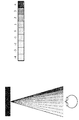
통상적으로, 무안경 입체영상 디스플레이들은 뷰들의 "콘들(cones)"을 생성하고, 각각의 콘은 장면의 상이한 시야각들에 대응하는 다수의 뷰들을 포함한다. 인접한(또는 어떤 경우들에는 더 멀어질) 뷰들 사이의 시야각 차는 사용자의 오른쪽 눈과 왼쪽 눈 사이의 시야각 차에 대응하도록 생성된다. 따라서, 왼쪽 눈 및 오른쪽 눈이 두 개의 적절한 뷰들을 보는 뷰어는 3D 효과를 인식할 것이다. 9개의 상이한 뷰들이 뷰잉 콘에서 생성되는 이러한 시스템의 예가 도 1에 예시된다. Typically, spectacles stereoscopic displays produce "cones" of views, and each cone includes multiple views corresponding to different viewing angles of the scene. The viewing angle difference between adjacent (or in some cases further) views is created to correspond to the viewing angle difference between the user's right and left eyes. Thus, a viewer that sees two appropriate views of the left eye and right eye will recognize the 3D effect. An example of such a system in which nine different views are generated in the viewing cone is illustrated in FIG.
많은 무안경 입체영상 디스플레이들은 다수의 뷰들을 생성할 수 있다. 예를 들면, 9개의 뷰들을 생성하는 무안경 입체영상 디스플레이들이 드물지 않다. 이러한 디스플레이들은, 예를 들면 여러 뷰어들이 동시에 디스플레이를 시청하고 모두 3D 효과를 경험할 수 있는 멀티-뷰어 시나리오들(multi-viewer scenarios)에 적합하다. 예를 들면 28개의 상이한 뷰들을 제공할 수 있는 디스플레이들을 포함하여, 더 많은 수의 뷰들을 가진 디스플레이들이 또한 개발되었다. 이러한 디스플레이들은 뷰어의 눈이 복수의 뷰들로부터 동시에 광을 수신하도록 비교적 좁은 뷰 콘들을 종종 이용할 수 있다. 또한, 왼쪽 눈 및 오른쪽 눈은 통상적으로 인접하지 않는 뷰들에 배치될 것이다(도 1의 예에서와 같이).Many non-eyeglass stereoscopic displays can generate multiple views. For example, non-eyeglass stereoscopic displays that generate nine views are not uncommon. These displays are suitable for multi-viewer scenarios, for example, where multiple viewers can simultaneously view the display and experience all of the 3D effects. Displays with a greater number of views have also been developed, including for example displays capable of providing 28 different views. These displays can often utilize relatively narrow view cones so that the viewer's eye receives light from multiple views simultaneously. Also, the left eye and right eye will typically be placed in non-contiguous views (as in the example of Figure 1).
멀티-뷰 디스플레이의 이미지들에 대한 선예도(sharpness)를 증가시키기 위한 이미지 처리 방식의 예는 EP 제2 259 601 A호에 개시된다. 듀얼 이미지 디스플레이를 위한 크로스-토크 감소의 예는 US 제2008/0231547 A1호에 제공된다. US 제2009/0079680 A1호는 듀얼-뷰 디스플레이에서 광 누설을 보상하기 위한 방법을 개시한다. 다수의 뷰들을 제공하기 위해 렌티큘러 렌즈 어레이를 이용하는 무안경 입체영상 디스플레이의 구체적인 예는 GB 제2 314 203호에 제공된다. An example of an image processing scheme for increasing the sharpness of images in a multi-view display is disclosed in
무안경 입체영상 디스플레이들은 통상적으로 렌티큘러 또는 시차-배리어 기술(lenticular or parallax-barrier technology)을 이용하여 무-안경 3D 효과를 생성한다.The non-eyeglass stereoscopic displays typically use lenticular or parallax-barrier technology to create a no-glasses 3D effect.
도 2는 다수의 서브-픽셀들로부터 3D 픽셀(3개의 색 채널들을 가진)의 형성예를 도시한다. 상기 예에서, w는 수평 서브-픽셀 피치이고, h는 수직 서브-픽셀 피치이고, N은 단색 패치 당 서브-픽셀들의 평균 개수이다. 렌티큘러 렌즈는 s = tan θ만큼 기울어지고, 수평 방향으로 측정된 피치는 서브-픽셀 피치 단위의 p이다. 3D 픽셀 내에서, 굵은 선들은 상이한 색상들의 패치들 사이의 분리를 나타내고 가는 선들은 서브-픽셀들 사이의 분리를 나타낸다. 다른 유용한 양은 서브-픽셀 종횡비: α = w/h이다. 그 다음 N = α/s이다. RGB-줄무늬 패턴 상의 일반 기울기 1/6 렌즈에 대해, α = 1/3 및 s = 1 / 6이고, 따라서 N = 2이다.Figure 2 shows an example of the formation of 3D pixels (with three color channels) from multiple sub-pixels. In this example, w is the horizontal sub-pixel pitch, h is the vertical sub-pixel pitch, and N is the average number of sub-pixels per monochromatic patch. The lenticular lens is inclined by s = tan &thetas; and the pitch measured in the horizontal direction is p in the sub-pixel pitch unit. Within a 3D pixel, thick lines represent separation between patches of different colors and thin lines represent separation between sub-pixels. Another useful amount is the sub-pixel aspect ratio: [alpha] = w / h. Then N = α / s. For a
무안경 입체영상 설계들에 내재된 것은 인접한 뷰들 사이의 일정량의 크로스-토크이며, 이는 유사한 방향으로 렌즈를 통해 들어오는 인접한 (서브-)픽셀들로부터의 광의 일부에 의해 유발된다. What is implicit in non-eyeglass stereoscopic designs is a certain amount of cross-talk between adjacent views, which is caused by a portion of the light from adjacent (sub-) pixels coming through the lens in a similar direction.
크로스-토크에 대항하는 통상적 방식은 동일한 위치의 현재 뷰에서 이웃하는 뷰들의 가중된 버전을 차감함으로써 광 크로스-토크를 상쇄하려고 시도하는 것이다. 이것은 추가적인 선예도를 유발하지만, 또한 다수의 한계들을 가진다. 예를 들면, 신호 값들이 일정 범위로 제한되고(통상적으로 표준 디스플레이들에 대해서는 8 비트, HDR 디스플레이들에 대해서는 더 많은 비트), 크로스-토크 보상이 밝은 점에 더 많이 추가(또는 어두운 점에서 동등하게 차감)되는 경우, 값은 극값들(8-비트의 경우에 0 또는 255)로 클리핑될 것이다.A typical approach to cross-talk is to attempt to offset optical cross-talk by subtracting the weighted version of the neighboring views in the current view of the same location. This causes additional sharpness, but also has a number of limitations. For example, if the signal values are limited to a certain range (typically 8 bits for standard displays and more bits for HDR displays), the cross-talk compensation adds more to the bright point , The value will be clipped to extreme values (0 or 255 in the case of 8-bits).
무안경 입체영상 디스플레이들이 가진 일반적인 문제는 밴딩(banding)으로 알려져 있고 렌티큘러 렌즈에 의한 블랙 매트릭스의 확대로 인한 비자발적 강도 변화로 규정될 수 있다. 도 3은 디스플레이가 모놀리식 서브-픽셀들을 가질 때 밴딩이 종종 광범위한 기울기 각도들에 대해 회피되거나 상당히 감소될 수 있는 것을 보여준다. 단순한 직사각형 서브-픽셀들을 이용하면 대부분의 밴딩은 라인 A로 도시된 바와 같이 직립(기울어지지 않은) 렌티큘러 렌즈들에 대해 발생할 것이다. 라인 A가 열 방향으로 스캐닝할 때, 강도는 라인을 따라 통합함으로써 보일 수 있다. 대부분의 다른 기울기 각도들에 대해, 렌즈 라인 B는 픽셀 그리드를 스캐닝할 때 발광 및 비-발광 영역들의 유사한 양들에 걸쳐 통합하고, 따라서 강도 변화(및 밴딩)가 거의 없다(즉, 누적된 강도는 렌즈 라인 B의 수평 위치에 의존하지 않는다).A common problem with non-eyeglass stereoscopic displays is known as banding and can be defined as the involuntary intensity change due to the expansion of the black matrix by a lenticular lens. Figure 3 shows that banding can often be avoided or significantly reduced over a wide range of tilt angles when the display has monolithic sub-pixels. With simple rectangle sub-pixels, most of the banding will occur for upright (un-tilted) lenticular lenses as shown by line A. When line A is scanning in the column direction, the intensity can be seen by incorporating along the line. For most other tilt angles, lens line B integrates over similar amounts of light-emitting and non-light-emitting regions when scanning a pixel grid, and thus has little intensity variation (and banding) And does not depend on the horizontal position of the lens line B).
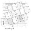
그러나, 도 4의 예와 같은 다른 기하학적 배열들에 대해, 밴딩은 대부분의 기울기 각도들에 대해 발생할 가능성이 있다. 이러한 시나리오들은 일반적으로 서브-픽셀들이 다수의 광학 소자들로 구성된 디스플레이들에 대해 발생한다. 이러한 디스플레이들에 대한 패널들은 점점 더 일반적이고 달성 가능한 이미지 품질의 관점에서 이점들을 제공한다. 그러나, 이러한 패널들을 포함하는 렌티큘러 디스플레이들은 또한 혼탁(moire)하고 크로스-토크하려는 경향이 있고 이것은 선예도를 낮게 퇴색시켜 하이라이트한다. 따라서, 현재 달성된 이미지 품질은 디스플레이 기술에 의해 약속된 것을 충족하지 않는 경향이 있다.However, for other geometric arrangements, such as the example of FIG. 4, banding is likely to occur for most tilt angles. These scenarios generally occur for displays whose sub-pixels are composed of a plurality of optical elements. Panels for these displays are increasingly common and provide advantages in terms of achievable image quality. However, lenticular displays including these panels also tend to moire and cross-talk, which is highlighted by fading low sharpness. Thus, currently achieved image quality tends not to meet what is promised by the display technology.
따라서, 무안경 입체영상 디스플레이들을 구동하기 위한 개선된 방식이 유리할 것이고, 특히 향상된 유연성, 개선된 이미지 품질, 감소된 복잡성, 감소된 리소스 요구 및/또는 개선된 성능을 허용하는 방식이 유리할 것이다. Thus, an improved approach to driving spectacles stereoscopic image displays would be advantageous, and in particular a way that allows for increased flexibility, improved image quality, reduced complexity, reduced resource requirements, and / or improved performance would be advantageous.
따라서, 본 발명은 바람직하게 상기 언급된 단점들 중 하나 이상을 단독으로 또는 임의의 조합으로 완화, 경감 또는 제거하도록 추구한다.Accordingly, the present invention preferably seeks to alleviate, alleviate or eliminate one or more of the above-mentioned disadvantages singly or in any combination.
본 발명의 일 양태에 따라 무안경 입체영상 디스플레이의 서브-픽셀들에 대한 서브-픽셀 구동 값들을 생성하기 위한 장치가 제공되며, 상기 장치는: 제공될 적어도 하나의 이미지의 픽셀들에 대한 광 출력 값들을 수신하기 위한 제 1 수신기; 및 서브-픽셀 구동 값들을 생성하기 위한 구동기로서, 제 1 서브-픽셀이 일부인 픽셀에 대한 광 출력 값에 응답하여, 적어도 하나의 다른 서브-픽셀의 서브-픽셀 값에 응답하여, 및 무안경 입체영상 디스플레이의 서브-픽셀들에 대한 서브-픽셀 크로스-토크 특징들을 반영하는 크로스-토크 패턴에 응답하여, 제 1 서브-픽셀에 대한 제 1 구동 값을 생성하도록 구성되는 상기 구동기를 포함하고, 구동기는 서브-픽셀들에 대한 서브-픽셀 구동 값들을 극단의 구동 값들쪽으로 바이어스하도록 구성된다. There is provided an apparatus for generating sub-pixel drive values for sub-pixels of a spectacles stereoscopic image display in accordance with an aspect of the present invention, the apparatus comprising: a light output A first receiver for receiving the values; And a driver for generating sub-pixel drive values, responsive to an optical output value for a pixel that is part of the first sub-pixel, responsive to sub-pixel values of at least one other sub-pixel, Pixel, the driver configured to generate a first drive value for a first sub-pixel in response to a cross-talk pattern reflecting sub-pixel cross-talk characteristics for sub-pixels of the image display, Are configured to bias the sub-pixel drive values for sub-pixels towards extreme drive values.
본 발명은 무안경 입체영상 디스플레이를 구동하기 위한 개선된 방법을 제공할 수 있고, 특히 많은 시나리오들에서 개선된 이미지 품질을 제공할 수 있다. 이 방식은 많은 시나리오들에서 향상된 연색성, 감소된 혼탁성, 증가된 선예도, 감소된 크로스-토크 및/또는 감소된 밴딩을 제공할 수 있다. 본 발명은 많은 실시예들에서 효율적인 구현을 허용하고, 서브-픽셀 구동 값들의 생성이 비교적 낮은 자원 사용(구체적으로 비교적 낮은 계산 및 메모리 자원을 사용)과 함께 비교적 낮은 복잡도 접근방식에 의할 수 있다. The present invention can provide an improved method for driving a spectacles stereoscopic image display, and in particular can provide improved image quality in many scenarios. This approach can provide improved color rendering, reduced turbidity, increased sharpness, reduced cross-talk, and / or reduced banding in many scenarios. The present invention allows an efficient implementation in many embodiments, and the generation of sub-pixel drive values can be made with a relatively low complexity approach with relatively low resource usage (specifically using relatively low computation and memory resources) .
장치는, 서브-픽셀 크로스-토크를 고려하고 서브-픽셀 구동 값들을 극단의 값들을 향함으로써 중간-범위 값들로부터 멀어지게 구동함에 의해 서브-픽셀들을 독립적으로 제어하도록 구성될 수 있다. The apparatus can be configured to independently control the sub-pixels by considering the sub-pixel cross-talk and driving the sub-pixel drive values away from the mid-range values by directing them to extreme values.
광 출력 값들은 구체적으로 적어도 하나의 이미지에 대한 픽셀 값들로서 제공될 수 있다. 많은 실시예들에서, 광 출력 값들/픽셀 값들은, 예를 들면 적색, 녹색 및 청색 채널에 대해 상이한 값들이 제공되는 것과 같이, 개별 색 채널들에 대해 제공될 수 있다. 따라서, 광 출력 값들은 디스플레이에 의해 제공될 하나 이상의 이미지들의 픽셀들에 대한 RGB 값들일 수 있다. 광 출력 값들은 적어도 하나의 이미지에 대한 원하는 픽셀 광 출력을 표현할 수 있다. The light output values may be specifically provided as pixel values for at least one image. In many embodiments, the light output values / pixel values may be provided for individual color channels, for example, different values are provided for the red, green, and blue channels. Thus, the light output values may be RGB values for pixels of one or more images to be provided by the display. The light output values may represent a desired pixel light output for at least one image.
적어도 하나의 이미지는 이미지들의 각각이 상이한 뷰에 대응하는 복수의 인터리브된 이미지들을 포함하는 직조 이미지일 수 있다. 적어도 하나의 이미지는 이미지들의 시퀀스의 이미지, 구체적으로 예를 들면 비디오 시퀀스의 이미지 또는 프레임일 수 있다.The at least one image may be a woven image comprising a plurality of interleaved images, each of the images corresponding to a different view. The at least one image may be an image of a sequence of images, specifically an image or frame of a video sequence, for example.
구동기는, 제 1 서브-픽셀이 일부인 픽셀로부터의 광 출력을 픽셀에 대한 광 출력 값에 의해 표시되는 광 출력과 유사해지도록 유발하기 위해 서브-픽셀 구동 값들을 선택하려고 추구하도록 구성될 수 있다. 제 1 서브-픽셀 구동 값의 주어진 값에 대응하는 광 출력의 결정은 다른 서브-픽셀들로부터 크로스-토크 기여들을 포함할 수 있다. 기여는 크로스-토크 패턴에 기초하여 결정될 수 있다. 일부 실시예들에서, 복수의 서브-픽셀들에 대한 구동 값들의 동시 결정이 수행될 수 있고, 값들은 픽셀에 대한 광 출력 값에 의해 반영된 광 출력에 대응하도록 선택될 수 있지만 공동 결정은 개별 서브-픽셀들에 가능한 한 극단의 값들을 할당하도록 추구한다. 예를 들면, 두 개의 서브-픽셀들을 포함하는 픽셀에 대한(예를 들면 특정 서브-채널에 대한) 50%의 광 출력에 대해, 구동기는 그 서브-픽셀로부터의 광 출력을 최소화하도록 하나의 서브-픽셀 구동 값을 설정하도록 구성될 수 있고 필요한 광은 다른 서브-픽셀에 의해 독점적으로 제공된다(예를 들면, 서브-픽셀들 둘다 50%로 설정하기보다, 구동기는 하나를 100%로 다른 하나를 0%로 설정할 수 있다).The driver may be configured to seek to select the sub-pixel drive values to cause the light output from the pixels that are part of the first sub-pixel to be similar to the light output represented by the light output value for the pixel. Determination of the light output corresponding to a given value of the first sub-pixel drive value may comprise cross-torque contributions from other sub-pixels. The contribution can be determined based on the cross-talk pattern. In some embodiments, a simultaneous determination of drive values for a plurality of sub-pixels may be performed and the values may be selected to correspond to the optical power reflected by the optical output value for the pixel, - seek to assign the extreme values to the pixels as much as possible. For example, for a light output of 50% (for a particular sub-channel, for example) for a pixel comprising two sub-pixels, the driver may provide one sub- Pixels can be configured to set the pixel drive value and the required light is provided exclusively by other sub-pixels (e.g., rather than setting both sub-pixels to 50% Can be set to 0%).
일부 실시예들에서, 제 1 서브-픽셀 구동 값은 픽셀에 대한 광 방사 값에 의해 나타난 값과는 상이한 픽셀로부터 광 방출을 유발하는 값으로 설정될 수 있다. 구체적으로, 제 1 서브-픽셀 구동 값은 원하는 광 출력과 상이한 광 출력을 희생하여 더욱 극단의 값으로 설정될 수 있다. 일부 실시예들에서, 잠재적으로 다른 픽셀들에 속하는 다른 서브-픽셀들에 대한 구동 값들을 결정할 때 차가 고려될 수 있다. 예를 들면, 광 출력이 하나의 픽셀에 대해 너무 높으면, 이웃 픽셀에 대해서는 너무 낮게 설정될 수 있다. In some embodiments, the first sub-pixel drive value may be set to a value that causes light emission from a pixel that is different from the value represented by the optical emission value for the pixel. Specifically, the first sub-pixel driving value may be set to a more extreme value at the expense of the light output different from the desired light output. In some embodiments, the difference can be taken into account when determining drive values for other sub-pixels belonging to potentially other pixels. For example, if the light output is too high for one pixel, it may be set too low for neighboring pixels.
크로스-토크 패턴은 서브-픽셀들의 광 출력이 다른 서브-픽셀들의 광 출력에 및 구체적으로 다른 서브-픽셀들에 대한 구동 값들에 의존하는 방법을 반영할 수 있다. 일부 실시예들에서, 크로스-토크 패턴은, 예를 들어, 주어진 서브-픽셀에 대해 이 서브-픽셀로부터 방사하게 될 다른 서브-픽셀들로부터의 광의 비율을 규정하는 필터일 수 있다. 일부 실시예들에서, 크로스-토크 패턴은 예를 들면, 주어진 서브-픽셀에 대해 다른 서브-픽셀들로부터 방사하게 될 이 서브-픽셀들로부터의 광의 비율을 규정하는 필터일 수 있다. 구체적으로, 일부 실시예들에서, 크로스-토크 패턴은 제 1 서브-픽셀에서 다른 픽셀들(통상적으로, 제 1 서브-픽셀의 이웃에 있는)로의 광 분배를 규정하는 필터일 수 있다. 일부 실시예들에서, 크로스-토크 패턴은 다른 픽셀들(통상적으로, 제 1 서브-픽셀의 이웃에 있는)에서 제 1 서브-픽셀로의 광 분배를 규정하는 필터일 수 있다. The cross-talk pattern may reflect how the light output of the sub-pixels depends on the light output of the other sub-pixels and specifically on the driving values for the other sub-pixels. In some embodiments, the cross-talk pattern may be, for example, a filter that defines the ratio of light from other sub-pixels to be emitted from this sub-pixel for a given sub-pixel. In some embodiments, the cross-talk pattern may be, for example, a filter that defines the ratio of light from these sub-pixels to be emitted from other sub-pixels for a given sub-pixel. Specifically, in some embodiments, the cross-talk pattern may be a filter that defines the light distribution from the first sub-pixel to other pixels (typically in the neighborhood of the first sub-pixel). In some embodiments, the cross-talk pattern may be a filter that defines the light distribution from the other pixels (typically in the neighborhood of the first sub-pixel) to the first sub-pixel.
서브-픽셀 구동 값들에 대한 바이어싱은 더욱 극단의 구동 값들을, 즉 구동 값들에 대한 범위의 종점들에 가까운 구동 값들을 향할 수 있다. 구체적으로, 서브-픽셀들을 더 어둡게 만드는 구동 값들쪽으로 어두운 서브-픽셀들을 바이어스하고, 서브-픽셀들을 더 밝게 만드는 구동 값들쪽으로 밝은 서브-픽셀들을 바이어스할 수 있다. Biasing for sub-pixel drive values can drive more extreme drive values, i.e. drive values close to the end points of the range for drive values. Specifically, it is possible to bias the dark sub-pixels toward the driving values which make the sub-pixels darker and to bias the bright sub-pixels towards the driving values which make the sub-pixels brighter.
서브-픽셀 구동 값들의 극단의 구동 값들쪽으로의 바이어싱은 구동 값들의 중간점 또는 중간-범위에서 멀어지는 구동 값들의 바이어싱일 수 있다. 구동 값들은 최소 광 출력에 대응하는 최소 값에서 최대 광 출력에 대응하는 최대 값까지의 범위에 있을 수 있다. 바이어싱은 최대 값과 최소 값에 가장 근접한 값을 향할 수 있다. 바이어싱은 최대 값과 최소 값 사이의 중간점에서 멀어질 수 있고, 일부 실시예들에서 중간점을 포함하는 값들의 범위에서 멀어질 수 있다.Biasing towards extreme driving values of sub-pixel driving values may be biasing driving values away from mid-point or mid-range of driving values. The driving values may range from a minimum value corresponding to the minimum light output to a maximum value corresponding to the maximum light output. Biasing can be directed to the values closest to the maximum and minimum values. The biasing can be far from the midpoint between the maximum and minimum values and, in some embodiments, can be farther from the range of values including the midpoint.
일부 실시예들에서, 장치를 포함하는 무안경 입체영상 디스플레이가 제공될 수 있다. 일부 실시예들에서, 장치를 포함하는 집적 회로가 제공될 수 있다. In some embodiments, a spectacles stereoscopic image display including an apparatus may be provided. In some embodiments, an integrated circuit including an apparatus may be provided.
무안경 입체영상 디스플레이는 서브-픽셀들을 포함하는 디스플레이 패널 및 디스플레이 패널 및 그에 따라 서브-픽셀들을 오버레이하는 뷰 형성/분리 광학 소자(view forming/ separating optical element)를 포함할 수 있다. 크로스-토크 패턴은 서브-픽셀 크로스-토크 특징들을 반영하는 임의의 데이터일 수 있고, 구체적으로, 상이한 서브-픽셀들의 광 출력들 사이의 상관을 표현할 수 있다. The spectacles stereoscopic display may include a display panel including sub-pixels and a view forming / separating optical element that overlays the display panel and thus the sub-pixels. The cross-talk pattern can be any data that reflects the sub-pixel cross-talk characteristics and, in particular, can represent the correlation between the light outputs of different sub-pixels.
많은 실시예들에서, 무안경 입체영상 디스플레이는 서브-픽셀들을 포함하는 디스플레이 패널과 디스플레이 패널/서브-픽셀들을 오버레이하는 뷰 형성 광학 소자를 포함하고, 크로스-토크 패턴은 뷰 형성 광학 소자의 특징들을 반영한다. In many embodiments, the spectacles stereoscopic display includes a display panel including sub-pixels and a view-forming optical element overlaying the display panel / sub-pixels, wherein the cross- Reflect.
구동기는, 서브-픽셀들의 세트에 대한 선택된 서브-픽셀 구동 값들로부터 발생하는 추정된 광 출력과 서브-픽셀들의 세트의 서브-픽셀들이 일부인 픽셀들에 대한 광 출력 값들에 대응하는 광 출력 사이의 거리를 반영하는 패널티 측정치를 최소화하는 최적화에 의해 서브-픽셀 구동 값들을 생성하도록 구성되고, 패널티 측정치는 또한 적어도 하나의 서브-픽셀 구동 값에 대한 가장 근접한 종단 범위 값에 대한 적어도 하나의 서브-픽셀 구동 값의 거리에 의존한다.The driver calculates the distance between the estimated light output resulting from the selected sub-pixel drive values for the set of sub-pixels and the light output corresponding to the light output values for the pixels that are part of the sub-pixels of the set of sub- Pixel drive values for at least one sub-pixel drive value, wherein the penalty measurement is further configured to generate sub-pixel drive values by optimization that minimizes penalty measurements that reflect at least one sub- Depends on the distance of the value.
이것은 개선된 성능을 제공할 수 있고 적어도 하나의 이미지에 가깝게 대응하는 광 출력을 생성하면서 극단의 값들쪽으로의 바이어스를 달성할 수 있다. This can provide improved performance and achieve a bias toward extreme values while producing a light output that closely corresponds to at least one image.
많은 실시예들에서, 패널티 측정치는 복수의 패널티 값들을 포함하는 복합 측정치일 수 있다. 많은 실시예들에서, 패널티 측정치는 다수의 파라미터들에 의존할 수 있다. In many embodiments, the penalty measurement may be a composite measurement comprising a plurality of penalty values. In many embodiments, the penalty measurement may depend on a number of parameters.
많은 실시예들에서, 패널티 측정치는 중간점 구동 값에 대한 적어도 하나의 서브-픽셀 구동 값의 거리에 의존할 수 있고, 중간점/중간범위 구동값은 서브-픽셀에 대한 중간 또는 평균 광 출력에 대응한다.In many embodiments, the penalty measurement may depend on the distance of at least one sub-pixel drive value to the mid-point drive value, and the mid-point / mid-range drive value may depend on the intermediate or average light output for the sub- Respectively.
많은 실시예들에서, 패널티 측정치는 적어도 하나의 구동 값에 대한 가장 근접한 종단 범위 값에 대한 적어도 하나의 구동 값의 거리의 일정하게 증가하는 함수인 패널티 값을 포함할 수 있다. 많은 실시예들에서, 패널티 측정치는 중간-범위 구동 값에 대한 적어도 하나의 구동 값의 거리의 일정하게 감소하는 함수인 페널티 값을 포함할 수 있다. In many embodiments, the penalty measurement may include a penalty value that is a constantly increasing function of the distance of at least one drive value to the nearest end range value for at least one drive value. In many embodiments, the penalty measure may comprise a penalty value that is a function that is a constant decreasing of the distance of at least one drive value relative to the mid-range drive value.
최적화는 구체적으로 이차 프로그래밍 최적화일 수 있다. 최적화가 종종 비결정 난해(NP(Nondeterministic Polynomial time) hard) 문제로 보일 수 있으므로 최적화는 종종 빠른 근사(fast approximation)일 수 있다. The optimization may specifically be a secondary programming optimization. Optimization can often be a fast approximation since optimization can often appear to be a problem of NP (Nondeterministic Polynomial time) hard.
본 발명의 선택적인 특징에 따라, 무안경 입체영상 디스플레이는 서브-픽셀들을 포함하는 디스플레이 패널 및 디스플레이 패널에 오버레이된 뷰 형성 광학 소자를 포함하고, 크로스-토크 패턴은 디스플레이 패널에서의 서브-픽셀들 사이의 공간 근접성을 반영한다. According to an optional feature of the present invention, the spectacles stereoscopic image display comprises a display panel comprising sub-pixels and a view-forming optical element overlaid on the display panel, wherein the cross- Lt; / RTI >
이것은 개선된 성능을 제공할 수 있고, 특히 많은 실시예들 및 시나리오들에서 개선된 이미지 품질을 제공할 수 있다. This can provide improved performance and can provide improved image quality, especially in many embodiments and scenarios.
뷰 형성 광학 소자는 구체적으로 렌티큘러 렌즈 소자, 배리어 마스크 또는 시차 배리어일 수 있다. The view forming optical element may be specifically a lenticular lens element, a barrier mask, or a parallax barrier.
본 발명의 선택적인 특징에 따라, 무안경 입체영상 디스플레이는 서브-픽셀들을 포함하는 디스플레이 패널 및 디스플레이 패널에 오버레이된 뷰 형성 광학 소자를 포함하고, 크로스-토크 패턴은 디스플레이 패널에서의 서브-픽셀들 사이의 뷰 상관을 반영한다. According to an optional feature of the present invention, the spectacles stereoscopic image display comprises a display panel comprising sub-pixels and a view-forming optical element overlaid on the display panel, wherein the cross- Lt; / RTI >
이것은 개선된 성능을 제공할 수 있고, 특히 많은 실시예들 및 시나리오들에서 개선된 이미지 품질을 제공할 수 있다. 특히, 이것은 개선된 무안경 입체영상 3D 이미지 렌더링을 제공할 수 있다. 두 개의 서브-픽셀들에 대한 뷰 상관은 두 개의 서브-픽셀들이 속하는 뷰들의 근접성을 나타낼 수 있다. 특히, 이것은 서브-픽셀들이 동일한 뷰에 속하는지, 인접한 뷰들에 속하는지 또는 다른 떨어진 뷰들에 속하는지를 반영할 수 있다. This can provide improved performance and can provide improved image quality, especially in many embodiments and scenarios. In particular, this can provide improved no-eye stereoscopic 3D image rendering. View correlation for two sub-pixels may indicate the proximity of the views to which the two sub-pixels belong. In particular, this may reflect whether the sub-pixels belong to the same view, belong to adjacent views, or belong to other distant views.
본 발명의 선택적인 특징에 따라, 크로스-토크 패턴은 인간의 시각 공간 대비 함수를 반영한다. According to an optional feature of the invention, the cross-talk pattern reflects the human visual space contrast function.
이것은 개선된 성능을 제공할 수 있고, 특히 많은 실시예들 및 시나리오들에서 인식 개선된 이미지 품질을 제공할 수 있다. This can provide improved performance and can provide improved image quality, especially in many embodiments and scenarios.
일부 실시예들에서 크로스-토크 패턴은 서브-픽셀들 사이의 색 상관을 반영할 수 있다. In some embodiments, the cross-talk pattern may reflect the color correlation between the sub-pixels.
본 발명의 선택적인 특징에 따라, 구동기는 제 1 서브-픽셀로부터의 원하는 광 출력에 대응하는 제 1 서브-픽셀에 대한 기준 구동 값을 결정하도록 구성되고, 원하는 광 출력은 제 1 서브-픽셀이 속하는 픽셀에 대한 광 출력 값에 대응하는 제 1 서브-픽셀로부터의 광 출력 기여도를 포함하고, 구동기는 기준 구동 값을 가장 근접한 종단 범위 구동 값에 더 가깝게 수정함으로써 제 1 서브-픽셀 구동 값을 결정하도록 구성된다. According to an optional feature of the present invention, the driver is configured to determine a reference drive value for a first sub-pixel corresponding to a desired light output from the first sub-pixel, Pixel drive value from the first sub-pixel corresponding to the optical output value for the pixel belonging to the first sub-pixel, and the driver determines the first sub-pixel drive value by modifying the reference drive value closer to the nearest end range drive value .
구동기는 더욱 극단의 구동값이 픽셀(그 색 채널에 대한)의 광 출력을 그 픽셀에 대한 광 출력 값에 의해 명시된 것과 상이하게 되는 것을 야기할 수 있더라도, 더욱 극단의 구동 값을 선택하도록 구성될 수 있다. 따라서, 생성된 광 출력의 차 또는 에러는 서브-픽셀 구동 값을 더욱 극단의 값을 취하도록, 즉 어두운 서브-픽셀을 더 어둡게 밝은 픽셀을 더 밝게 허용하기 위해 의도적으로 도입될 수 있다.The driver may be configured to select a more extreme driving value even though the extreme driving value may cause the optical output of the pixel (for that color channel) to differ from that specified by the optical output value for that pixel . Thus, the difference or error in the generated light output can be intentionally introduced to take the sub-pixel drive value to a more extreme value, i. E. To allow a darker sub-pixel to be brighter than a darker bright pixel.
구동기는 따라서, 픽셀에 대한 광 출력 값에 의해 규정된 바와 같은 광 출력 기여를 제공하도록 단순히 추구하는 것으로부터 초래되는 값에 대응하는 것보다 더욱 극단적이게 되도록 서브-픽셀 값(들)을 결정할 수 있다. The driver can thus determine the sub-pixel value (s) to be more extreme than corresponding to the value resulting from simply seeking to provide the light output contribution as defined by the light output value for the pixel .
이것은 개선된 성능을 제공할 수 있고, 특히 많은 실시예들 및 시나리오들에서 개선된 이미지 품질을 제공할 수 있다. This can provide improved performance and can provide improved image quality, especially in many embodiments and scenarios.
본 발명의 선택적인 특징에 따라, 구동기(905)는 기준 구동 값에 대한 제 1 서브-픽셀 구동 값에 대한 차 측정에 응답하여 에러 잔류(error residue)를 결정하고; 서브-픽셀들의 그룹에 걸쳐 상기 에러 잔류를 분산하도록 구성된다. According to an optional feature of the present invention, the
이것은 개선된 성능을 제공할 수 있고 개선된 이미지 품질을 허용할 수 있다. 이 방식은 서브-픽셀들에 더욱 극단의 구동 값들이 할당되도록 허용하면서 그에 의해 도입된 임의의 왜곡의 효과가 감소되도록 허용할 수 있다. This can provide improved performance and allow improved image quality. This approach allows the sub-pixels to be assigned more extreme driving values while allowing the effect of any distortion introduced thereby to be reduced.
에러 잔류는 더욱 극단의 구동 값을 선택함으로써 서브-픽셀의 광 출력에 도입된 에러를 반영할 수 있고, 즉 기준 구동 값에 대한 수정을 반영할 수 있다. 에러 잔류는 예를 들면, 서브-픽셀 구동 값들로서 표현되고, 분석되고, 처리되고 및/또는 결정될 수 있고 및/또는 예를 들면, 서브-픽셀 광 출력 측정치들로서 표현되고, 분석되고, 처리되고 및/또는 결정될 수 있다.The error residual can reflect the error introduced into the light output of the sub-pixel by selecting a more extreme driving value, i.e. it can reflect a correction to the reference driving value. The error residual may be represented, analyzed, processed and / or determined, for example, as sub-pixel drive values and / or represented, for example, as sub-pixel light output measurements, analyzed, / ≪ / RTI >
에러 잔류의 분산은 하나 이상의 다른 서브-픽셀들에 대한 것일 수 있다. 분산은 제 1 서브-픽셀의 에러 잔류를 보상하기 위해 하나 이상의 다른 서브-픽셀들에 대한 원하는 광 출력을 수정할 수 있다. The variance of the error residue may be for one or more other sub-pixels. The dispersion can modify the desired light output for one or more other sub-pixels to compensate for the error residual of the first sub-pixel.
일부 실시예들에서, 구동기는 에러 잔류로부터 적어도 하나의 다른 서브-픽셀에 대한 보상 광 출력 값을 결정함으로써 에러 잔류를 분산하도록 구성될 수 있다. 적어도 하나의 다른 서브-픽셀에 대한 광 출력 값은 보상 광 출력 값에 응답하여 수정될 수 있고, 적어도 하나의 다른 서브-픽셀에 대한 기준 구동 값은 수정된 광 출력 값에 기초하여 결정될 수 있다.In some embodiments, the driver can be configured to distribute the error residue by determining a compensated light output value for at least one other sub-pixel from the error residue. The optical output value for at least one other sub-pixel may be modified in response to the compensated optical output value, and the reference drive value for at least one other sub-pixel may be determined based on the modified optical output value.
분산은 에러 잔류로부터 서브-픽셀들의 세트의 각각에 대한 보상을 기술하는 분산 필터에 의할 수 있다. 분산 필터는 구체적으로, 에러 잔류가 분산되는 서브-픽셀의 이웃에 있는 각각의 서브-픽셀에 대한 기여를 기술하는 공간 필터에 의해 표현될 수 있다. 공간 필터는 행렬로 표현될 수 있고, 에러 잔류에 의한 행렬의 곱은 공간 필터에 의해 커버되는 이웃에 있는 각각의 서브-픽셀에 보상 값들을 제공하는 보상 행렬을 유발할 수 있다. The variance may be from a residual error to a variance filter describing the compensation for each of the set of sub-pixels. The dispersion filter can be represented in particular by a spatial filter that describes the contribution of each sub-pixel in the neighborhood of the sub-pixel where the error residual is dispersed. The spatial filter may be represented as a matrix and the product of the matrix due to error residual may cause a compensation matrix to provide compensation values to each sub-pixel in the neighborhood covered by the spatial filter.
에러 잔류는 구체적으로 공간 디더링(spatial dithering)에 의해 분산될 수 있다. The error residual can be specifically dispersed by spatial dithering.
많은 실시예들에서, 보상 광 출력 값들의 조합은 에러 잔류와 실질적으로 동일할 수 있다.In many embodiments, the combination of the compensated light output values may be substantially the same as the residual error.
본 발명의 선택적인 특징에 따라, 구동기는 다른 서브-픽셀들로부터 제 1 서브-픽셀로의 에러 잔류 기여들에 응답하여 기준 구동 값을 결정하도록 구성된다. According to an optional feature of the invention, the driver is configured to determine a reference drive value in response to error residual contributions from the other sub-pixels to the first sub-pixel.
이것은 개선된 이미지 품질을 제공할 수 있고 특히 더욱 극단의 구동 값들을 인가함으로 유발된 인식 왜곡을 감소시킬 수 있다.This can provide improved image quality and can reduce recognition distortion caused by applying even more extreme driving values.
본 발명의 선택적인 특징에 따라, 구동기는: 서브-픽셀들 사이의 공간 근접성; 서브-픽셀들 사이의 뷰 상관; 서브-픽셀들 사이의 색 상관; 및 인간의 시각 공간 대비 함수에 응답하여 에러 잔류를 분산하도록 구성된다. According to an optional feature of the invention, the actuator comprises: a spatial proximity between the sub-pixels; View correlation between sub-pixels; Color correlation between sub-pixels; And to distribute error residuals in response to the human visual space contrast function.
이것은 특히 유리한 성능을 제공할 수 있고 많은 실시예들에서 디스플레이된 이미지의 이미지 품질을 높일 수 있다.This can provide particularly advantageous performance and in many embodiments can enhance the image quality of the displayed image.
일부 실시예들에서, 구동기는 에러 잔류에서 서브-픽셀들의 그룹으로의 기여들을 규정하는 에러 잔류 분산 필터(error residue distribution filter)를 이용하여 에러 잔류를 분산하도록 구성될 수 있다. 에러 잔류 분산 필터는 공간적 근접성 필터, 뷰 상관 필터, 시정 필터(visibility filter) 및 색 상관 필터 중 적어도 일부를 조합하여 생성된 합성 필터일 수 있다.In some embodiments, the driver can be configured to distribute the error residue using an error residue distribution filter that defines contributions from the residual error to the group of sub-pixels. The error residual dispersion filter may be a composite filter generated by combining at least some of the spatial proximity filter, the view correlation filter, the visibility filter, and the color correlation filter.
본 발명의 선택적인 특징에 따라, 서브-픽셀들에 대한 구동 값들을 순차적으로 결정하고; 서브-픽셀에 후속하는 서브-픽셀들에만 서브-픽셀에 대한 에러 잔류를 분산하도록 구성된다. According to an optional feature of the present invention, the driving values for sub-pixels are determined sequentially; And to distribute error residuals to the sub-pixels only in the sub-pixels subsequent to the sub-pixel.
이것은 복잡도를 감소시킬 수 있고 계산 자원을 실질적으로 감소시킬 수 있다. 이것은 많은 실시예들에서 구동기가 단일 패스에서 구동 값들을 결정하기 위해 적어도 하나의 이미지를 처리하도록 허용할 수 있으며, 즉 각각의 구동 값은 한번만 결정되고 반복 또는 재귀 알고리즘이 필요하지 않는다. This can reduce complexity and substantially reduce computational resources. This in many embodiments allows the driver to process at least one image to determine drive values in a single pass, i.e. each drive value is determined only once and does not require an iterative or recursive algorithm.
본 발명의 선택적인 특징에 따라, 무안경 입체영상 디스플레이는 제 1 세트의 뷰들에 대한 인터리브된 이미지들을 포함하는 직조 이미지를 제공함으로써 제 1 세트의 뷰들을 디스플레이하도록 구성되고, 장치는: 제 2 세트의 뷰들에 대한 적어도 하나의 이미지를 수신하기 위한 제 2 수신기; 및 제 2 세트의 뷰들에 대한 적어도 하나의 이미지로부터 직조 이미지를 생성하기 위한 이미지 조합기를 더 포함하고, 구동기는 직조 이미지의 서브-픽셀들을 처리함으로써 서브-픽셀 구동 값들을 결정하도록 구성된다. According to an optional feature of the present invention, a spectacles stereoscopic image display is configured to display a first set of views by providing a woven image comprising interleaved images for a first set of views, the apparatus comprising: A second receiver for receiving at least one image for the views of the first image; And an image combiner for generating a woven image from at least one image for the second set of views, wherein the driver is configured to determine sub-pixel drive values by processing sub-pixels of the woven image.
이것은 개선된 성능을 제공할 수 있고 또는 많은 실시예들에서 감소된 복잡도를 허용할 수 있다. This may provide improved performance or may allow reduced complexity in many embodiments.
본 발명의 선택적인 특징에 따라, 무안경 입체영상 디스플레이는 제 1 세트의 뷰들에 대한 인터리브된 이미지들을 포함하는 직조 이미지를 제공함으로써 제 1 세트의 뷰들을 디스플레이하도록 구성되고, 장치는: 제 2 세트의 뷰들에 대한 적어도 하나의 이미지를 수신하기 위한 수신기를 더 포함하고, 구동기는 제 2 세트의 뷰들에 대한 적어도 하나의 이미지의 서브-픽셀들을 처리함으로써 서브-픽셀 구동 값들을 직조 이미지의 서브-픽셀 구동 값들로서 결정하도록 구성된다. According to an optional feature of the present invention, a spectacles stereoscopic image display is configured to display a first set of views by providing a woven image comprising interleaved images for a first set of views, the apparatus comprising: Wherein the driver processes the sub-pixels of the at least one image for the second set of views to generate the sub-pixel drive values for the sub-pixels of the woven image by processing the sub- As drive values.
이것은 개선된 성능을 제공할 수 있고 또는 많은 실시예들에서 감소된 복잡도를 허용할 수 있다.This may provide improved performance or may allow reduced complexity in many embodiments.
본 발명의 선택적인 특징에 따라, 적어도 하나의 이미지는 이미지 프레임들의 시퀀스의 이미지이고 구동기는 후속 이미지들 사이에서 이미지들의 개별 서브-픽셀들에 대한 바이어스를 변화시키도록 구성된다. According to an optional feature of the invention, the at least one image is an image of a sequence of image frames and the driver is configured to vary the bias for individual sub-pixels of the images between subsequent images.
이것은 많은 실시예들에서 개선된 인식 이미지 품질을 제공할 수 있다. This can provide improved recognition image quality in many embodiments.
본 발명의 일 양태에 따라, 무안경 입체영상 디스플레이의 서브-픽셀들에 대한 서브-픽셀 구동 값들을 생성하는 방법이 제공되며, 상기 방법은: 제공될 적어도 하나의 이미지의 픽셀들에 대한 광 출력 값들을 수신하는 단계; 및 서브-픽셀 구동 값들을 생성하는 단계로서, 제 1 서브-픽셀이 일부인 픽셀에 대한 광 출력 값에 응답하여, 적어도 하나의 다른 서브-픽셀의 서브-픽셀 값에 응답하여, 및 무안경 입체영상 디스플레이의 서브-픽셀들에 대한 서브-픽셀 크로스-토크 특징들을 반영하는 크로스-토크 패턴에 응답하여, 제 1 서브-픽셀에 대한 제 1 구동 값을 생성하는 단계를 포함하는 상기 서브-픽셀 구동 값들의 생성 단계를 포함하고, 서브-픽셀 구동 값들의 생성 단계는 서브-픽셀들의 세트에 대한 선택된 서브-픽셀 구동 값들로부터 발생하는 추정된 광 출력과 서브-픽셀들의 세트의 서브-픽셀들이 일부인 픽셀들에 대한 광 출력 값들에 대응하는 광 출력 사이의 거리를 반영하는 패널티 측정치를 최소화하는 최적화에 의해 서브-픽셀 구동 값들을 생성함으로써 서브-픽셀들에 대한 서브-픽셀 구동 값들을 극단의 구동 값들쪽으로 바이어스하는 단계를 포함하고, 패널티 측정치는 또한 적어도 하나의 서브-픽셀 구동 값에 대한 가장 근접한 종단 범위 값에 대한 선택된 서브-픽셀 구동 값들의 적어도 하나의 서브-픽셀 구동 값의 거리에 의존한다.According to an aspect of the present invention there is provided a method of generating sub-pixel drive values for sub-pixels of a spectacles stereoscopic image display, the method comprising: providing a light output for pixels of at least one image to be provided Receiving values; And generating sub-pixel drive values in response to the sub-pixel values of at least one other sub-pixel, in response to an optical output value for a pixel that is part of the first sub-pixel, Pixel drive value in response to a cross-talk pattern reflecting sub-pixel cross-talk characteristics for sub-pixels of the display, comprising generating a first drive value for a first sub- Wherein the step of generating the sub-pixel drive values comprises a step of generating the estimated optical output resulting from the selected sub-pixel drive values for the set of sub-pixels, Pixel drive values by optimization that minimizes penalty measurements that reflect the distance between the light outputs corresponding to the light output values for the sub- Pixel drive values for at least one sub-pixel drive value toward the extreme drive values, wherein the penalty measurement is also for at least one of the selected sub-pixel drive values for the closest end- Lt; RTI ID = 0.0 > sub-pixel < / RTI >
본 발명의 이들 및 다른 양태들, 특징들 및 이점들은 이후 기술되는 실시예(들)을 참조하여 명백해지고 명료해질 것이다. These and other aspects, features, and advantages of the present invention will be apparent from and elucidated with reference to the embodiment (s) described hereinafter.
본 발명의 실시예들은 도면들을 참조하여 단지 예의 방식으로 기술될 것이다.
도 1은 무안경 입체영상 디스플레이로부터 생성된 뷰들의 일례를 도시한 도면.
도 2는 무안경 입체영상 디스플레이의 디스플레이 패널을 오버레이하는 렌티큘러 스크린의 일례를 도시한 도면.
도 3은 무안경 입체영상 디스플레이의 디스플레이 패널의 레이아웃의 일례를 도시한 도면.
도 4는 무안경 입체영상 디스플레이의 디스플레이 패널의 레이아웃의 일례를 도시한 도면.
도 5는 무안경 입체영상 디스플레이 디바이스의 소자들의 개략적인 사시도.
도 6은 무안경 입체영상 디스플레이 디바이스의 소자들의 단면도.
도 7은 렌티큘러가 중첩되게 나타난, 디스플레이 패널 상의 서브-픽셀들의 레이아웃의 개략도.
도 8은 도 7의 레이아웃 및 렌티큘러로 획득 가능한 무안경 입체영상 이미지의 하나의 뷰의 개략도.
도 9는 본 발명의 일부 실시예들에 따라 디스플레이 구동기의 소자들의 일례를 도시한 도면.
도 10은 무안경 입체영상 디스플레이에 대한 크로스-토크 패턴들의 일례를 도시한 도면.Embodiments of the present invention will now be described, by way of example only, with reference to the drawings.
BRIEF DESCRIPTION OF THE DRAWINGS Figure 1 shows an example of views generated from a spectacles stereoscopic image display.
2 is a view showing an example of a lenticular screen overlaying a display panel of a non-eyeglass stereoscopic image display.
3 is a view showing an example of a layout of a display panel of a spectacle-free three-dimensional image display.
4 is a view showing an example of a layout of a display panel of a spectacle-free three-dimensional image display.
5 is a schematic perspective view of elements of a spectacles stereoscopic image display device.
6 is a cross-sectional view of elements of a spectacles stereoscopic image display device.
Figure 7 is a schematic view of the layout of sub-pixels on a display panel, with the lenticules overlapping.
Figure 8 is a schematic view of one view of a non-eyeglass stereoscopic image obtainable with the layout and lenticular of Figure 7;
9 illustrates an example of elements of a display driver in accordance with some embodiments of the present invention.
Figure 10 shows an example of cross-talk patterns for a spectacles stereoscopic image display.
다음에는 독립적으로 어드레싱 가능한(통상적으로 적어도 하나의 로우 라인 및 컬럼 라인을 이용하여) 광-변조 소자를 표시하기 위해 용어 "서브-픽셀"이 이용될 것이다. 서브-픽셀들은 또한 어드레싱 가능한 독립적인 색 구성요소로 칭해진다. 통상적으로, 서브-픽셀은 액티브 매트릭스 셀 회로를 포함한다. 광은 서브-픽셀에서 광의 방출, 반사율 및/또는 투과를 변경함으로써 변조될 수 있다. 광은 서브-픽셀 자체에서 생성될 수도 있거나, 광은, LCD 프로젝터와 같은 프로젝터에 이용하기 위해, 서브 픽셀의 외부에 있는 광원에서 발생할 수 있음을 유념한다. 서브-픽셀은 또한 '셀(cell)'로 칭해진다.Subsequently, the term "sub-pixel" will be used to indicate the light-modulating elements that are independently addressable (typically using at least one row line and column line). The sub-pixels are also referred to as addressable independent color components. Typically, the sub-pixels comprise an active matrix cell circuit. The light can be modulated by changing the emission, reflectivity and / or transmission of light in the sub-pixels. Note that light may be generated in the sub-pixel itself, or light may occur in a light source outside the sub-pixel, for use in a projector such as an LCD projector. The sub-pixels are also referred to as 'cells'.
용어 '픽셀(pixel)'은 디스플레이가 생성할 수 있는 모든 색들을 생성할 수 있는 병치된 서브-픽셀들의 최소 그룹을 표시하기 위해 이용될 것이다. 픽셀들은 또한 어드레싱 가능한 독립적인 풀 컬러로 칭해진다.The term " pixel " will be used to indicate the smallest group of juxtaposed sub-pixels that can produce all of the colors that a display can produce. The pixels are also referred to as addressable, independent full colors.
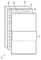
도 5는 무안경 입체영상 디스플레이의 개략적인 사시도를 도시한다. 도 6은 도 5에 도시된 디스플레이의 개락적 단면도를 도시한다.Figure 5 shows a schematic perspective view of a spectacles stereoscopic image display. Figure 6 shows an exploded cross-sectional view of the display shown in Figure 5;
무안경 입체영상 디스플레이(501)는 디스플레이 패널(503)을 포함한다. 디스플레이(501)는 예를 들면 디스플레이가 LCD형 디스플레이일 때, 필수적인 것은 아니지만 예를 들면 OLED형 디스플레이들에 대해, 광원(507)을 포함할 수 있다.The non-eyeglass
디스플레이 디바이스(501)는 또한 디스플레이 패널(503)의 디스플레이측 위에 구성된 렌티큘러 시트(509)를 포함하며, 이것은 뷰 형성 기능을 수행한다. 렌티큘러 시트(509)는 서로 평행하게 연장하는 렌티큘러 렌즈들(511)의 로우를 포함하고, 그중 하나만 명확성을 위해 과장된 크기로 도시된다. 렌티큘러 렌즈들(511)은 뷰 형성 기능을 수행하기 위해 뷰 형성 소자들로서 동작한다. 도 5의 렌티큘러 렌즈들은 디스플레이 패널의 반대쪽을 향하는 볼록부(convex)를 가진다. 볼록부측이 디스플레이 패널쪽을 향하도록 렌티큘러 렌즈들을 형성하는 것도 또한 가능하다.The
렌티큘러 렌즈들(511)은 볼록한 원통형 소자들의 형태일 수 있고, 렌티큘러 렌즈들(511)은 디스플레이 패널(503)로부터 상이한 이미지들 또는 뷰들을 디스플레이 디바이스(501)의 전면에 위치된 사용자의 눈에 제공하기 위한 광 출력 지향 수단(light output directing means)으로 동작한다. The
도 5에 도시된 무안경 입체영상 디스플레이 디바이스(501)는 상이한 방향들의 여러 개의 상이한 사시적 뷰들을 제공할 수 있다. 특히, 각각의 렌티큘러 렌즈(511)는 각각의 로우의 디스플레이 서브-픽셀들(505)의 작은 그룹을 오버레이한다. 렌티큘러 소자(511)는 여러 상이한 뷰들을 형성하도록, 그룹의 각각의 디스플레이 서브-픽셀(505)을 상이한 방향들로 투사한다. 사용자의 머리가 좌측에서 우측으로 이동할 때, 사용자의 눈은 차례로 여러 뷰들 중 상이한 뷰들을 수용할 것이다. The non-eyeglass stereoscopic
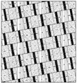
도 7은 렌티큘러가 중첩되게 나타난, 디스플레이 패널 상의 서브-픽셀들의 레이아웃의 개략도를 도시한다. 서브-픽셀들의 RGB-줄무늬 레이아웃이 도시된다; 이들 중 3개는 픽셀들을 형성한다. 디스플레이 패널에서, 적색, 녹색 및 청색의 컬럼들이 반복되는 직사각형 그리드 상에서 서브-픽셀들이 구성된다. 패널 상에서 중첩된 렌티큘러가 도시된다. 렌티큘러가 서브-픽셀 레이아웃에서 컬럼들에 대해 기울어짐을 유념한다. 도 7에서, 렌즈-효과는 도시되지 않는다.Figure 7 shows a schematic view of the layout of sub-pixels on a display panel in which the lenticular appears superimposed. An RGB-stripe layout of sub-pixels is shown; Three of these form pixels. In a display panel, sub-pixels are constructed on a rectangular grid in which the red, green and blue columns are repeated. A superimposed lenticular on the panel is shown. Note that the lenticular is tilted with respect to the columns in the sub-pixel layout. In Fig. 7, the lens-effect is not shown.
도 8은 도 7의 레이아웃 및 렌티큘러로 획득 가능한 무안경 입체영상 이미지의 하나의 뷰의 개략도를 도시한다. 도 7 및 도 8 둘다에서, 흑색 막대들을 볼 수 있다. 후자는 예를 들면, 데이터 라인들, 어드레스 라인들 등을 지지하기 위한 패널의 비-이미지 형성 부분들에 대응한다. 막대들은 렌티큘러의 확대 효과로 인해 도 8에서 약간 더 넓다. Figure 8 shows a schematic of one view of the non-eyeglass stereoscopic image obtainable with the layout and lenticular of Figure 7; In both FIG. 7 and FIG. 8, black bars can be seen. The latter corresponds to, for example, non-image forming portions of the panel for supporting data lines, address lines, and the like. The bars are slightly wider in FIG. 8 due to the expansion effect of the lenticular.
특정 예가 렌티큘러 스크린의 형태의 뷰 형성층에 기초하지만, 예를 들면, 시차 배리어와 같은 다른 소자들이 다른 실시예들에서 이용될 수 있음을 알 것이다. It will be appreciated that certain examples are based on a view-forming layer in the form of a lenticular screen, but other elements, such as parallax barriers, for example, may be used in other embodiments.
도 9는 무안경 입체영상 디스플레이(501)에 대한 디스플레이 구동기(901)의 소자들의 예를 도시한다. 디스플레이 구동기(901)는 무안경 입체영상 디스플레이의 일체화된 부분일 수 있거나, 별도의 엔티티 또는 디바이스일 수 있다. 예를 들면, 디스플레이 구동기(901)는 일체화된 회로(주문형 IC, FPGA 등)로 구현될 수 있고 이러한 IC는 잠재적으로 디스플레이의 부분이거나 별도의 보드 또는 디바이스의 부분이다. 9 shows an example of the elements of the
디스플레이 구동기(901)는 무안경 입체영상 디스플레이(501) 상에 제공된 직조 이미지를 수신하는 제 1 수신기(903)를 포함한다. 당업자에게 알려진 바와 같이, 렌티큘러 스크린은 이웃하는 픽셀들을 상이한 방향들로 투사할 수 있고 그에 의해 복수의 뷰들을 생성한다. 통상적으로, 인접하는 픽셀들은 따라서 상이한 뷰들에 속하고, 실제로 픽셀들은 통상적으로 픽셀 컬럼들의 그룹들로 분할되고 각각의 그룹은 각각의 뷰를 위한 픽셀 컬럼을 포함한다. 따라서 디스플레이 패널은 컬럼 그룹들로 분할될 수 있고 각각의 그룹은 각각의 뷰를 위한 하나의 픽셀 컬럼을 포함한다. 주어진 뷰에서 수평으로 인접한 픽셀들은 상이한 그룹들에 속하고 디스플레이 패널(503) 상의 수평으로 인접한 픽셀들은 상이한 뷰들을 위한 이미지들에 속한다. The
예를 들면, N개의 뷰들(N은 통상적으로 예를 들면 9 또는 28일 수 있음)을 디스플레이할 수 있는 무안경 입체영상 디스플레이는 기본적으로 N개의 이미지들을 렌더링할 수 있고 N개의 이미지들의 각각은 하나의 뷰에 대응한다. 이것은 N개의 픽셀 컬럼들을 포함하는 컬럼 그룹들을 형성함으로써 달성되고 하나의 픽셀 컬럼은 뷰 이미지들의 각각에 포함된다. 픽셀 컬럼들의 순서는 뷰들의 순서에 대응하고 뷰 이미지들에서의 인접한 컬럼들은 인접한 컬럼 그룹들에 포함된다. N개의 뷰 이미지들 모두가 인터리브된 결과로서 생긴 이미지는 그 후에 디스플레이 패널 상에서 렌더링되고 렌티큘러 렌즈는 상이한 방향들에서 렌더링되는 상이한 뷰 이미지들을 유발한다. 디스플레이 패널(503) 상에서 렌더링되는 인터리브된 이미지는 직조 이미지로서 알려져 있다. For example, a non-eyeglass stereoscopic display capable of displaying N views (where N may be typically 9 or 28, for example) can basically render N images and each of the N images is one Lt; / RTI > This is accomplished by forming column groups containing N pixel columns and one pixel column is included in each of the view images. The order of the pixel columns corresponds to the order of the views and the adjacent columns in the view images are included in the adjacent column groups. The resultant image of all of the N view images interleaved is then rendered on the display panel and the lenticular lens causes different view images to be rendered in different directions. The interleaved image rendered on the
제 1 수신기는 임의의 외부 또는 내부 소스로부터 직조 이미지를 수신할 수 있고, 예를 들면 펌웨어 루틴이 별도의 뷰 이미지들로부터 직조 이미지를 생성함으로써, 직조 이미지가 저장될 수 있는 메모리 버퍼로서 구현될 수 있다. The first receiver may receive a woven image from any external or internal source and may be implemented as a memory buffer in which a woven image may be stored, for example, by a firmware routine generating a woven image from separate view images have.
제 1 수신기(903)는 구동기(905)에 연결되고, 구동기(905)는 직조 이미지로부터 디스플레이 패널의 서브-픽셀들에 대한 구동 값들을 생성하도록 구성된다. 직조 이미지는 픽셀에 대한 원하는 광 출력을 기술하는 픽셀 값들에 의해 표현된다. 통상적으로, 적색, 녹색 및 청색 색 채널에 대한 또는 예를 들면 적색, 녹색, 청색 및 백색 색 채널에 대한 것과 같이, 복수의 색 채널들에 대한 각각의 픽셀에 광 값들이 제공된다(즉, 원하는 광 출력들은 RGB 또는 RGBW 값들에 의해 기술될 수 있다). 많은 실시예들에서, RGBW (또는 RGBY) 값들과 같은 다원색 값들이 디스플레이를 위한 구동기에서의 예를 들면 RGB 값들로부터 도출될 수 있다. 일부 실시예들에서, 제 1 수신기(903)는 그러한 다원색 값들로의 변환을 위한 기능을 포함할 수 있다. The
구동기(905)는 직조 이미지에 대한 광 출력 값들에 기초하여 디스플레이 패널에 대한 서브-픽셀 구동 값들을 생성하도록 구성된다. 구동기(905)는 구체적으로 렌더링된 뷰 이미지들이 제 1 수신기(903)에 의해 수신된 광 출력 값들에 의해 기술되는 이미지들에 가장 가깝게 대응하도록(적절한 기준에 따라 통상적으로 상이한 관련 품질 특징들 및 특성들을 고려하여) 서브-픽셀들 구동 값들을 생성하도록 추구할 수 있다. The
많은 실시예들에서, 디스플레이 패널은 적어도 하나의 색 채널들에 대한 각각의 픽셀에 대해 복수의 서브-픽셀들을 포함할 수 있다. 예를 들면, 각 픽셀에 대해, 두 개의 개별적으로 어드레싱 가능한 녹색 발광 소자들이 있을 수 있고, 즉 각각의 픽셀은 2개의 녹색 서브-픽셀들을 포함할 수 있다. 픽셀 당 이러한 복수의 서브-픽셀들은 디스플레이 패널(503)을 구동하는 방법에서 향상된 유연성 및 부가의 자유를 제공할 수 있다. In many embodiments, the display panel may comprise a plurality of sub-pixels for each pixel for at least one color channels. For example, for each pixel, there may be two individually addressable green light emitting elements, i.e. each pixel may comprise two green sub-pixels. These multiple sub-pixels per pixel can provide enhanced flexibility and added freedom in the manner of driving the
도 9의 시스템에서, 구동기는 디스플레이의 크로스-토크 특징들을 고려하여 서브-픽셀들을 생성하도록 구성된다. 구체적으로, 발광 소자로부터 방출된 광은 광학 소자의 특정 영역 이외의 다른 영역들에 확산될 수 있다. 구동기(905)는 이러한 광 분배를 고려한다. In the system of Figure 9, the driver is configured to generate sub-pixels in consideration of the cross-talk characteristics of the display. Specifically, the light emitted from the light emitting element can be diffused to other regions than the specific region of the optical element. The
구체적으로, 주어진 서브-픽셀에 대한 구동 값을 결정할 때, 구동키(905)는, 서브-픽셀이 속하는 픽셀에 대한 픽셀 값/광 출력 값에 의해 규정되는 바와 같이 원하는 광 출력을 고려한다. 구체적으로, 이것은 픽셀에 대한 광 출력을 원하는 광 출력에 가깝게 유발하는 서브-픽셀 구동 값을 결정하도록 추구할 수 있다. 구동기(905)는 상이한 서브-픽셀 구동 값들로부터 발생하는 광 출력을 결정할 수 있고 주어진 기준을 가장 잘 충족하는 값을 선택할 수 있다. 광 출력을 계산할 때, 구동기(905)는 픽셀에 속하는 모든 서브-픽셀들(및 그 색 채널)로부터 광 출력을 고려할 수 있다. 또한, 이것은 다른 픽셀들의 서브-픽셀들로부터의 광의 크로스-토크에서 발생한 광 출력을 고려한다.Specifically, when determining the drive value for a given sub-pixel, the
특히, 서브-픽셀들 구동 값들을 결정할 때, 구동기(905)는 무안경 입체영상 디스플레이의 서브-픽셀들에 대한 서브-픽셀 크로스-토크 특징들을 반영하는 크로스-토크 패턴을 고려한다. 크로스-토크 패턴은 구체적으로 현재 서브-픽셀의 이웃에 있는 서브-픽셀들로부터의 크로스-토크를 기술하는 공간 필터일 수 있거나 또는 현재 서브-픽셀의 이웃에 있는 서브-픽셀들에 대한 크로스-토크를 기술하는 공간 필터일 수 있다. In particular, when determining the sub-pixel driving values, the
또한, 구동기(905)는 서브-픽셀들에 대한 서브-픽셀들 구동 값들을 극단의 구동 값들쪽으로 바이어스하도록 구성된다. 바이어싱은 구체적으로 구동 값들에 대한 값들의 범위의 종단 값들을 향할 수 있고, 구체적으로 서브-픽셀로부터 최소 및 최대 광 출력에 대응하는 구동 값들을 향할 수 있다. 일부 실시예들에서, 바이어싱은 구동 값들의 범위의 중간-범위 또는 중간-점으로부터 멀어질 수 있거나, 또는 구체적으로 서브-픽셀로부터 평균 또는 중간 광 출력에 대응하는 구동 값으로부터 멀어질 수 있다. In addition, the
구동기(905)는 따라서, 극단의 레벨들을 촉진하도록 디스플레이 크로스-토크 프로파일을 고려하는 알고리즘을 이용하여, 서브-픽셀들을 독립적으로 제어하도록 구성될 수 있다. The
바이어싱은 예를 들면, 구동기(905)가 다른 서브-픽셀들로부터의 크로스-토크를 고려하면서 픽셀의 모든 서브-픽셀들에 대한 모든 가능한 구동 값들에 대한 결과로서 생긴 픽셀 광 출력을 계산함으로써 달성될 수 있다. 구동 값들의 각각의 가능한 조합에 대해, 패널티 값이 계산될 수 있고 이것은 결과로서 생긴 광 출력이 픽셀 값에 의해 기술된 바와 같은 원하는 광 출력에 얼마나 가까운지, 및 구동 값이 얼마나 극단의지, 즉 이것이 가장 근접한 종단 범위 값에 얼마나 가까운지/중간범위 값으로부터 얼마나 먼지를 모두 고려한다. 패널티 값은 광 출력의 차가 클수록 증가할 수 있고 구동 값들이 극단적일수록 낮을 수 있다. 구동기(905)는 가장 낮은 패널티 값을 유발하는 구동 값들의 세트를 선택할 수 있다. 다른 실시예들에서, 구동기는 예를 들면 현재 서브-픽셀로부터 다른 서브-픽셀들에 유발된 크로스-토크를 최소화하도록 추구할 수 있다. Biasing can be achieved, for example, by calculating the resulting pixel light output for all possible drive values for all sub-pixels of the pixel, taking into account the cross-talk from the other sub-pixels, . For each possible combination of driving values, a penalty value can be calculated, which determines how close the resulting light output is to the desired light output, as described by the pixel values, and how extreme the driving value is, Consider how close to the closest end-of-range value / how far from the mid-range value. The penalty value can be increased as the difference in light output increases and the driving values can be lower as the extreme. The
극단의 값들쪽으로의 구동은 유리한 동작 및 특히 개선된 이미지 품질을 제공할 수 있다. 예를 들면, 이 방식은 뷰들 사이의 크로스-토크가 더 적은 더 선명한 3D 화상을 유발할 수 있다. Driving towards extreme values can provide favorable operation and especially improved image quality. For example, this approach can result in a sharper 3D image with less cross-talk between views.
일부 실시예들에서, 디스플레이 구동기(901)는 직조 이미지를 직접 수신할 수 있고, 제 1 수신기(905)는 제공될 직조 이미지를 직접 수신할 수 있다. 그러나 많은 실시예들에서, 디스플레이 구동기(901)는 하나 이상이 단일 뷰 이미지들로부터 직조 이미지를 생성하기 위한 기능을 포함할 수 있다. In some embodiments, the
직조 이미지는 무안경 입체영상 디스플레이에 의해 제공될 제 1 세트의 뷰들에 대한 인터리브된 이미지들을 포함한다. 제 1 세트의 뷰들은 예를 들면 9 또는 28개의 상이한 뷰들을 포함할 수 있다. The woven image includes interleaved images for a first set of views to be provided by a spectacle-free stereoscopic image display. The first set of views may include, for example, nine or twenty-eight different views.
도 9의 예에서, 디스플레이 구동기(901)는 제 2 세트의 뷰들에 대한 적어도 하나의 이미지를 수신하도록 구성되는 제 2 수신기(907)를 더 포함한다. 제 2 세트의 뷰들은 통상적으로 제 1 세트의 뷰들과 상이할 수 있다. In the example of FIG. 9,
제 2 수신기(907)는 이미지 조합기(909)에 연결되고, 이미지 조합기(909)는 또한 제 1 수신기(903)에 연결된다. 이미지 조합기(909)는 제 2 세트의 뷰들에 대한 적어도 하나의 이미지로부터 직조 이미지를 생성하고 결과로서 생긴 직조 이미지를 제 1 수신기(903)에 제공하도록 구성된다. 예를 들면, 이미지 조합기(909)는 수신된 입력 이미지(들)로부터 직조 이미지를 생성할 수 있고 결과로서 생긴 직조 이미지를 제 1 수신기(903)를 구현하는 메모리 버퍼에 저장할 수 있다.The
일부 실시예들에서 제 2 수신기(907)는 단일 뷰 이미지들을 수신할 수 있다. 이들 단일 뷰 이미지들은 일부 실시예들에서 무안경 입체영상 디스플레이에 의해 제공될 뷰 이미지들에 직접 대응할 수 있다. 예를 들면, 28개의 뷰 무안경 입체영상 디스플레이에 대해, 디스플레이 구동기(901)는 28개의 이미지들을 수신할 수 있고 각각의 이미지는 뷰들 중 하나에 대응한다. 이러한 예에서, 이미지 조합기(909)는 수신된 입력 단일 뷰 이미지들을 인터리브하고 조합함으로써 직조 이미지를 생성하도록 진행할 수 있다. In some embodiments, the
다른 실시예들에서, 수신된 단일 뷰 이미지들은 제공될 뷰 이미지들에 대응하지 않을 수 있다. 예를 들면, 더 높거나 낮은 수의 이미지들이 수신될 수 있다. 이러한 예들에서, 이미지 조합기(909)는 렌더링될 뷰들에 대응하는 단일 뷰 이미지들을 먼저 생성하도록 구성될 수 있고 그 후에 이들 이미지들을 인터리브함으로써 직조 이미지가 생성될 수 있다.In other embodiments, the received single view images may not correspond to the view images to be provided. For example, a higher or lower number of images may be received. In these examples, the
렌더링하기 위한 단일 뷰 이미지들의 생성은 수신된 이미지로부터 예를 들면, 보간 또는 외삽에 기초할 수 있다. 예를 들면, 일부 실시예들에서, 렌더링에 필요한 것보다 상당히 많은 수의 입력 단일 뷰 이미지들이 수신될 수 있다. 이러한 경우, 렌더링될 적절한 뷰 이미지들은 예를 들면 수신된 입력 이미지들로부터 보간 및/또는 선택에 의해 생성될 수 있다. The generation of single view images for rendering may be based on, for example, interpolation or extrapolation from the received image. For example, in some embodiments, a significantly greater number of input single view images may be received than are required for rendering. In this case, the appropriate view images to be rendered may be generated, for example, by interpolation and / or selection from the received input images.
일부 실시예들에서, 보다 소수의 입력 단일 뷰 이미지들이 수신될 수 있다. 예를 들면, 극단적인 경우에도 단일 입력 이미지가 수신될 수 있다. 이 경우, 이미지는 예를 들면 심도 정보와 연관될 수 있다(예를 들면, 이미지 플러스 심도 표현이 이용될 수 있다). 이 경우, 이미지 조합기(909)는 심도 정보에 기초하여 수신된 입력 이미지의 뷰 시프트에 의해 랜더링을 위한 이미지들을 생성하도록 구성될 수 있다. In some embodiments, a smaller number of input single view images may be received. For example, a single input image may be received in extreme cases. In this case, the image may be associated with, for example, depth information (e.g., an image plus depth representation may be used). In this case, the
다른 예를 들면, 제 2 수신기(907)는 입체영상 이미지(사용자의 왼쪽 눈 및 오른쪽 눈의 각각에 하나의 이미지)를 수신할 수 있고 이미지 조합기(909)는 직조 이미지에의 포함을 위해 적절한 뷰 이미지들을 생성하도록 이에 뷰 시프트를 적용하도록 진행할 수 있다. As another example, the
많은 실시예들에서, 구동기(905)는 복수의 서브-픽셀들을 동시에 고려할 수 있는 최적화를 수행하도록 추구할 수 있다. 많은 실시예들에서, 구동기(905)는 최적화에 의해 서브-픽셀들 구동 값들을 생성하도록 구성될 수 있고 최적화는 선택된 서브-픽셀들 구동 값들로부터 발생하는 추정된 광 출력과 광 출력 값들에 의해 기술된 광 출력 사이의 차를 반영하는 패널티 측정치를 최소화한다. 패널티 값은 이러한 차에 의존하고 적어도 하나의 구동 값에 대한 가장 근접한 종단 범위 값에 대한 적어도 하나의 서브-픽셀 구동 값의 거리에 의존하는 것일 수 있거나, 또는 등가적으로, 예를 들면 평균 또는 중간 광 출력에 대응하는 중간 또는 평균 구동 값에 대한 거리에 의존할 수 있다.In many embodiments, the
추정된 광 출력과 원하는 광 출력 사이의 일정한 차에 대해, 패널티 값은, 구동 값이 서브-픽셀에 대한 50% 광 출력에 대응하는 평균 구동 값에 가까울수록 증가할 수 있다. 유사하게, 일정한 구동 값, 및 따라서 평균 구동 값에 대한 일정한 거리에 대해, 패널티 값은, 그 구동 값에 대한 계산된 광 출력과 원하는 광 출력(이미지에 대한 수신된 픽셀 값들로부터 결정된 바와 같이) 사이의 차가 클수록 증가한다. For a constant difference between the estimated light output and the desired light output, the penalty value may increase as the drive value approaches the average drive value corresponding to 50% light output for the sub-pixels. Similarly, for a constant drive value, and hence a constant distance to the mean drive value, the penalty value is calculated by multiplying the calculated light output for that drive value by the desired light output (as determined from the received pixel values for the image) The greater the difference between the two.
추정된 광 출력은 다른 서브-픽셀들로부터의 크로스-토크로부터 발생하는 광을 고려하여 결정된다. 크로스-토크 기여는 디스플레이의 크로스-토크 특징들을 반영하는 패턴에 기초하여 결정된다.The estimated light output is determined in consideration of the light resulting from the cross-talk from the other sub-pixels. The cross-talk contribution is determined based on a pattern that reflects the cross-talk characteristics of the display.
복잡도가 낮은 특정 예를 들면, 구동기(905)는 직조 이미지의 각각의 픽셀을 순차적으로 처리하도록 진행할 수 있고, 예를 들면 좌상단 코너 픽셀에서 시작하여 주어진 순서로 모든 픽셀들을 통해 진행한다(예를 들면, 한 로우씩, 지그-재그, 미앤더링(meandering), 등). 또한, 구동기는 각각의 색 채널을 독립적으로 다루도록 진행할 수 있다.For a specific example of low complexity, the
예를 들면, 구동기(905)는 제 1 색 채널에 대해 및 각각의 픽셀마다 그 색 채널 및 그 픽셀의 서브-픽셀들의 모든 가능한 구동 값들에 대한 광 출력을 추정할 수 있다. 예를 들면, 픽셀이 색 채널의 2개의 서브-픽셀들을 포함하는 경우, 구동기(905)는 색 채널 서브-픽셀들에 대한 모든 가능한 쌍들의 구동 값들에 대한 픽셀로부터 광 출력을 평가하도록 진행할 수 있다.For example, the
각각의 가능한 조합에 대해, 결과로서 생긴 광 출력이 계산된다. 이 계산은 현재 픽셀의 서브-픽셀들로부터 출력되는 광을 고려하지만, 또한 다른 픽셀들의(통상적으로 동일한 색 채널의) 서브-픽셀들로부터의 크로스-토크 기여를 포함한다. 이 크로스-토크 기여는, 현재 픽셀로부터 출력되지만 다른 서브-픽셀들로부터 비롯되는 광량을 나타내는 크로스-토크 패턴에 기초하여 결정될 수 있다. For each possible combination, the resulting light output is calculated. This calculation takes into account the light output from the sub-pixels of the current pixel, but also includes the cross-talk contribution from sub-pixels (typically of the same color channel) of other pixels. This cross-talk contribution can be determined based on a cross-talk pattern that is output from the current pixel but which represents the amount of light that originates from other sub-pixels.
상기 예에서, 광 출력에 대한 크로스-토크 기여는 구동 값들이 이미 결정된 서브-픽셀들에만 기초하여 생성될 수 있다. 따라서, 후속 서브-픽셀들로부터의 크로스-토크 기여는 이러한 단계에서 고려하지 않는다. In this example, the cross-talk contribution to light output can be generated based only on the sub-pixels for which the drive values have already been determined. Thus, the cross-talk contribution from the subsequent sub-pixels is not taken into consideration at this stage.
크로스-토크로부터 및 모든 가능한 구동 값(조합들)에 대한 결과로서 생긴 광 출력이 결정되고, 추정된/계산된 광 출력과 입력 픽셀 값에 의해 규정된 바와 같은 원하는 광 출력 사이의 거리를 나타내는 거리 측정치가 계산된다. 하나의 단순한 차 값과 같이, 임의의 적합한 거리 측정치가 이용될 수 있음을 알 것이다. The resulting light output from the cross-talk and for all possible drive values (combinations) is determined and the distance between the estimated / calculated light output and the desired light output as defined by the input pixel value, A measurement is calculated. It will be appreciated that any suitable distance measure, such as one simple difference value, can be used.
구동기(905)는 그 후 각각의 가능한 구동 값 조합에 대한 패널티 값을 계산하도록 진행한다. 패널티 값은 구동 값(들)이 얼마나 극단인지와 거리 측정치에 의존한다. 패널티 값을 계산하는데 이용되는 특정 공식은 개별 실시예의 특징들 및 선호들에 의존할 것임을 알 것이다. 예를 들면, 일부 실시예들에서, 이것은 추정된 및 원하는 광 출력 사이의 차와, 각각의 구동 값과 평균 구동 값 사이의 차의 가중된 합으로서 계산될 수 있다. 가중치들은 원하는 성능을 제공하도록 조정될 수 있다. The
구동기(905)는 그 후에 최저 패널티 값을 유발하는 구동 값 조합을 선택하도록 진행한다. 따라서 현재 픽셀의 서브-픽셀들에 대한 서브-픽셀들 구동 값들은 최저 패널티 값을 유발하는 것들로 결정된다. The
구동기(905)는 그 후에 다음 픽셀로 진행하여 동일한 동작을 수행할 수 있다. 이 경우, 방금 결정된 픽셀에서 새로운 픽셀로의 크로스-토크가 추정된 광 출력을 결정할 때 고려될 것이다. The
모든 픽셀들이 처리되었으면, 구동 값들은 색 채널에 대한 모든 서브-픽셀들에 대해 생성되었다. 그러나, 구동 값들이 이전에 결정된 서브-픽셀들로부터만 크로스-토크 기여들을 고려하여 구동 값들이 생성되었다. 이것은 차선의 성능을 유발할 수 있고 구체적으로 감소된 이미지 품질을 유발할 수 있다. 따라서 구동기(905)는 제 2 패스를 수행하도록 진행할 수 있다. 제 2 패스에서의 방식은, 구동 값들이 제 1 패스에서 결정된 구동 값들을 이용함으로써 제 2 패스에서 아직 결정되지 않은 서브-픽셀들에 대해 크로스-토크 기여가 포함되는 것을 제외하고 제 1 패스에서의 방식과 동일할 수 있다. 일부 실시예들에서, 구동기(905)는 더욱 정확한 결과들을 결정하기 위해 더 많은 패스들(passes)을 수행할 수 있다.Once all of the pixels have been processed, the drive values have been generated for all sub-pixels for the color channel. However, drive values have been generated in consideration of cross-torque contributions only from sub-pixels whose drive values have been previously determined. This can cause lane performance and can result in reduced image quality in particular. Thus, the
더욱 복잡한 최적화 방식들이 다른 실시예들에서 이용될 수 있음을 알 것이다. 예를 들면, 이차 프로그래밍이 이용될 수 있다.It will be appreciated that more complex optimization schemes may be used in other embodiments. For example, secondary programming can be used.
특정 예를 들면, 이 방식은 ![]()
![]()
![]()
![]()
A는 크로스-토크 모델을 표현하는 희소 행렬이고(즉, A는 크로스-토크 패턴을 표현할 수 있고), ![]()
![]()
![]()
![]()
![]()
![]()
![]()
![]()
![]()
![]()

이 경우, 최적화 프로세스는 따라서 다음과 같이 표현될 수 있다:In this case, the optimization process can thus be expressed as:
![]()
![]()
![]()
![]()
![]()
![]()
![]()
![]()
실제로, 상기 문제는 작은수의 반복들에 의해 얼추 해결될 수 있고, 당업자는 이차 프로그래밍과 상이한 방식들을 알게 될 것이다..In practice, the problem can be solved by a small number of iterations, and one of ordinary skill in the art will know how to do it differently from secondary programming.
상기 방식은 구동 값들이 극단의 값들쪽으로, 구체적으로 서브-픽셀들의 완전히 OFF(0) 또는 완전히 ON(1) 설정에 대응하는 값들 쪽으로 바이어스되도록 허용한다. 이것은 0.5 근접하는 ![]()
![]()
구체적으로, 0.5 근접하는 ![]()
![]()
![]()
![]()
![]()
![]()
![]()
![]()
![]()
![]()

여기서 t는 기준 값들의 표현과 극단의 값들로의 구동 사이의 트레이드오프를 나타내는 양의 정수이다. Where t is a positive integer representing the tradeoff between the representation of the reference values and driving to extreme values.
크로스-토크 패턴은 무안경 입체영상 디스플레이의 크로스-토크 특징들의 기술을 제공한다. 크로스-토크 패턴은 또한 크로스토크의 뷰어의 영향을 반영하는 다양한 특징들 및 특성들을 반영하도록 결정될 수 있다. The cross-talk pattern provides a description of the cross-talk features of a spectacles stereoscopic display. The cross-talk pattern may also be determined to reflect various characteristics and characteristics reflecting the influence of the viewer of the crosstalk.
구체적으로, 크로스-토크 패턴은 일부 실시예들에서 디스플레이 패널의 서브-픽셀들 사이의 공간 근접성을 반영할 수 있다. 구체적으로, 서로에 가까운 서브-픽셀들은 통상적으로 멀리 떨어진 서브-픽셀들보다 높은 정도의 크로스-토크를 제공하고, 이것은 크로스-토크 패턴에 반영될 수 있다.Specifically, the cross-talk pattern may reflect spatial proximity between sub-pixels of the display panel in some embodiments. Specifically, sub-pixels close to each other typically provide a higher degree of cross-talk than sub-pixels away, which can be reflected in the cross-talk pattern.
일부 실시예들에서, 크로스-토크 패턴은 디스플레이 패널의 서브-픽셀들 사이의 뷰 상관을 반영할 수 있다. 뷰 상관은 서브-픽셀들 사이의 뷰 거리를 반영할 수 있다. 구체적으로, 크로스-토크 패턴은 서브-픽셀들이 동일한 뷰에, 또는 이웃하는 뷰들에, 또는 멀리 떨어진 뷰들에 속하는지를 반영할 수 있다. In some embodiments, the cross-talk pattern may reflect view correlation between sub-pixels of the display panel. View correlation may reflect the view distance between sub-pixels. Specifically, the cross-talk pattern may reflect whether the sub-pixels belong to the same view, to neighboring views, or to distant views.
따라서, 크로스-토크 패턴은, 직조 이미지에서의 인접한 서브-픽셀들(또는 픽셀들)이 멀리 떨어진 서브-픽셀들보다 높은 물리적 크로스-토크값을 가질 수 있지만, 멀리 떨어진 서브-픽셀들이 동일한 뷰 방향으로 향한다면 멀리 떨어진 서브-픽셀들의 지각된 영향이 훨씬 더 큰 효과를 가질 수 있다는 것을 반영할 수 있다. 따라서, 뷰 형성층(509)(렌티큘러 스크린)은 상이한 뷰 방향들의 디스플레이 패널(503)로부터의 광을 분리하고 이것은 크로스-토크 패턴에 반영될 수 있다. Thus, the cross-talk pattern may be such that adjacent sub-pixels (or pixels) in a woven image may have a higher physical cross-torque value than sub-pixels that are farther away, Lt; RTI ID = 0.0 > sub-pixels < / RTI > may have a much greater effect. Thus, the view-forming layer 509 (lenticular screen) separates light from the
상기 방식은 예를 들면 크로스-토크 패턴이 직조 이미지와 함께 직접 이용되도록 허용할 수 있다. 상기 방식이 크로스-토크 패턴을 나타내는 크로스-토크 필터가 이-차원 공간 모델로서 표현되도록 허용하기 때문에 이것은 효율적인 방식이다. The scheme may allow for example a cross-torque pattern to be used directly with the woven image. This is an efficient approach because the scheme allows the cross-torque filter representing the cross-torque pattern to be expressed as a two-dimensional spatial model.
일부 실시예들에서, 크로스-토크 패턴은 인간의 시각 공간 대비 함수를 반영할 수 있다. 인간의 시각 공간 대비 함수는 공간 주파수(크기)의 함수로서 인간의 눈에 라인 쌍들의 가시성을 반영한다. 공간 주파수는 통상적으로 시야각으로서 표현된다. 인간의 시각 공간 대비 함수는 따라서 공간 주파수의 함수로서 공간 대비에 대한 인간 관측자의 민감도를 반영한다.In some embodiments, the cross-talk pattern may reflect a human visual space contrast function. The human visual space contrast function reflects the visibility of line pairs in the human eye as a function of spatial frequency (magnitude). The spatial frequency is typically expressed as a viewing angle. The human visual space contrast function thus reflects the human observer's sensitivity to spatial contrast as a function of spatial frequency.
인간의 시각 공간 대비 함수의 이용은 작은 미세부분들이 뷰어에게 보이지 않는 것을 고려함에 따라 유리할 수 있고, 이것이 좀 더 공격적인 필터링이 적용되도록 허용한다.The use of the human visual space contrast function may be advantageous as considering that the smallest details are not visible to the viewer, which allows for more aggressive filtering to be applied.
일부 실시예들에서, 크로스-토크 패턴은 서브-픽셀들 사이의 색 상관을 반영할 수 있다. 통상적으로, 예를 들면, 구체적으로 RGB 디스플레이들에 대한 색 필터들은 색 채널들 사이의 무시할 만한 크로스-토크와 실질적으로 무관한 상이한 색 채널들을 유발할 것이다. 그러나, 일부 실시예들에서, 예를 들면 RGBW 디스플레이들과 같은 다원색 디스플레이들을 이용할 때, 상이한 색 채널 사이에 교차 상관이 있을 수 있다. In some embodiments, the cross-talk pattern may reflect the color correlation between sub-pixels. Typically, for example, color filters specifically for RGB displays will cause different color channels that are substantially independent of negligible cross-talk between color channels. However, in some embodiments, when using multi-primary displays such as, for example, RGBW displays, there may be cross-correlation between the different color channels.
이러한 시나리오들에서, 크로스-토크 패턴은 상이한 색 채널들 사이의 크로스-토크를 반영할 수 있다. 또한, 크로스-토크 패턴은 색 상관을 반영할 수 있고, 구체적으로 색 채널들이 스펙트럼으로 얼마나 유사한지를 반영할 수 있다. 예를 들면, W-서브-픽셀에서 G-서브-픽셀로의 교차 상관에 대해, 크로스-토크 값은 W 서브-픽셀로부터의 얼마나 많은 광이 G-서브-픽셀에 대응하는 주파수 통과 대역에 있는지를 반영할 수 있다. In such scenarios, the cross-talk pattern may reflect the cross-talk between different color channels. In addition, the cross-talk pattern can reflect color correlation and specifically reflect how similar color channels are to the spectrum. For example, for cross-correlation from a W-sub-pixel to a G-sub-pixel, the cross-talk value determines how much light from the W sub-pixel is in the frequency passband corresponding to the G- .
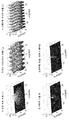
도 10은 직조 이미지에 직접 적용될 수 있는 필터 형태의 크로스-토크 패턴들의 일례를 도시한다. 도 10a는 공간 필터링을 도시한다(직조 이미지의 서브-픽셀들의 거리를 반영). 도 10b는 뷰 상관이 고려되는 뷰 필터링을 도시한다. 도 10c는 상이한 서브-픽셀들(통상적으로 다원색 패널들에 이용된)의 각각의 색들의 스펙트럼 유사성을 고려한다. 도 10d는 조합된 필터를 도시하고 도 10e는 조합된 필터의 희박한 버전(sparse version)을 도시한다.Figure 10 shows an example of filter-like cross-talk patterns that can be applied directly to a woven image. 10A shows spatial filtering (reflecting the distance of the sub-pixels of the woven image). Figure 10B shows view filtering where view correlation is considered. Figure 10C considers the spectral similarity of each of the colors of different sub-pixels (typically used in multi-primary panels). Fig. 10d shows the combined filter and Fig. 10e shows the sparse version of the combined filter.
일부 실시예들에서, 구동기(905)는, 각각의 서브-픽셀에 의해 생성된 광에 에러들을 도입함으로써 서브-픽셀 값들이 더 많은 극단의 값들을 취하도록 허용하지만 이들 에러들이 다른 서브-픽셀들에서 에러들을 대응시킴으로써 보상되기 위해, 공간 디더링 방식을 이용하도록 구성될 수 있다. In some embodiments, the
더욱 상세하게, 구동기는 주어진 서브-픽셀 구동 값을 서브-픽셀로부터 원하는 광 출력에 대응하는 기준 구동 값보다 서브-픽셀에 대한 극단의 구동 값에 더 가깝게 설정하도록 구성될 수 있다. More specifically, the driver can be configured to set a given sub-pixel drive value closer to the extreme drive value for the sub-pixel than the reference drive value corresponding to the desired light output from the sub-pixel.
구체적으로, 구동기(905)는 제 1 서브-픽셀로부터의 원하는 광 출력에 대응하는 제 1 서브-픽셀에 대한 기준 구동 값을 결정할 수 있다. 원하는 광 출력은 이것이 다른 픽셀들로부터의 기여들에 의해 보상된 후(구체적으로 크로스-토크 또는 에러 잔류 보상들) 입력 픽셀 값/광 출력 값에 의해 기술되는 것에 대응할 수 있다. 기준 구동 값은 따라서 이것에 대해 서브-픽셀에 의해 생성되어야 하는 광에 대응하여 다른 서브-픽셀들로부터의 광과 함께 수신된 광 출력 값에 의해 나타난 광 출력에 대응하는(그러나 가능하게는 후술되는 바와 같이 다른 서브-픽셀들로부터의 에러 잔류 기여들에 의해 보상되는) 광 출력을 제공한다.In particular, the
따라서 기준 구동 값은 원하는 광 출력을 제공하도록 결정되고 원하는 광 출력은 그 픽셀에 대한 수신된 광 출력 값에 대응하는 제 1 서브-픽셀로부터의 구성요소 또는 광 출력 기여를 포함한다. The reference drive value is thus determined to provide the desired light output and the desired light output comprises the component or light output contribution from the first sub-pixel corresponding to the received light output value for that pixel.
따라서, 기준 구동 값은 서브-픽셀로부터의 광 출력이 입력 픽셀 값에 따라 픽셀에 대한 원하는 광 출력을 유발하는 구동 값일 수 있다. Thus, the reference drive value may be a drive value that causes the light output from the sub-pixels to produce the desired light output for the pixel in accordance with the input pixel value.
구동기(905)는 이 기준 구동 값을 결정할 수 있고 그 후에 이를 더 많은 극단의 값쪽으로 수정하도록 진행할 수 있다. 구체적으로, 밝은 서브-픽셀은 더 밝게 만들어질 수 있고 어두운 서브-픽셀은 더 어둡게 만들어질 수 있다. 따라서, 구동기(905)는 상기 예에서 기준 구동 값을 가장 근접한 종단 범위의 기준 구동 값에 더 가깝게 수정함으로써 제 1 서브-픽셀 기준 구동 값을 결정하도록 구성된다.The
결과적으로, 픽셀로부터의 결과로서 생긴 광 출력은 에러 잔류를 보일 수 있다. 에러 잔류는 선택된 서브-픽셀 기준 구동 값과 기준 구동 값 사이의 차에 기초하여 결정될 수 있다. 에러 잔류는 일부 실시예들에서 추정된 광 출력과 원하는 광 출력 사이의 차로서, 즉 선택된 서브-픽셀 기준 구동 값으로부터 발생할 광 출력과 기준 구동 값으로부터 발생한 광 출력 사이의 차로서 계산될 수 있다. 일부 실시예들에서, 에러 잔류는 선택된 서브-픽셀 기준 구동 값과 기준 구동 값 사이의 차에 의해 직접 표현될 수 있다. As a result, the resulting light output from the pixel may show an error residual. The error residual can be determined based on the difference between the selected sub-pixel reference drive value and the reference drive value. The error residual can be calculated as the difference between the optical output estimated in some embodiments and the desired optical output, i.e. the difference between the optical output resulting from the selected sub-pixel reference drive value and the optical output resulting from the reference drive value. In some embodiments, the error residue may be directly represented by the difference between the selected sub-pixel reference drive value and the reference drive value.
구동기는 그 후에 에러 잔류를 다른 서브-픽셀들에 분산하고 구체적으로 에러 잔류를 서브-픽셀들의 그룹에 걸쳐 분산하도록 진행할 수 있다. 통상적으로 그룹은 이웃 서브-픽셀들의 그룹을 포함한다. 이웃 서브-픽셀들은 구체적으로 뷰 이웃 서브-픽셀들의 그룹일 수 있고, 즉 그룹은 에러 잔류가 계산되는 서브-픽셀과 동일한 뷰(또는 근처의 뷰들)에 속하는 서브-픽셀들을 포함하도록 선택될 수 있다. The driver can then proceed to distribute the error residue to the other sub-pixels and specifically to distribute the error residue across the group of sub-pixels. Typically, a group includes a group of neighboring sub-pixels. The neighboring sub-pixels may be specifically a group of view neighboring sub-pixels, i.e. the group may be selected to include sub-pixels belonging to the same view (or nearby views) as the sub-pixels for which the residual error is calculated .
에러 잔류는 보상 값들을 계산함으로써 그룹의 서브-픽셀들에 분산된다. 통상적으로, 보상 값은 에러 잔류를 보상하기 위해 다른 서브-픽셀에 대한 원하는 광 출력이 얼마나 많이 수정되어야 하는지를 반영한다. 다른 서브-픽셀들에 대한 총 보상은 통상적으로 에러 잔류에 대응하도록 선택되고, 즉 서브-픽셀들의 그룹의 서브-픽셀들에 대한 총 조합된 광 출력 변경은 현재 서브-픽셀에 대한 광 출력의 에러와 실질적으로 동일하도록 선택될 수 있다. The error residue is distributed to the sub-pixels of the group by calculating the compensation values. Typically, the compensation value reflects how much the desired light output for the other sub-pixel should be modified to compensate for the error residue. The total compensation for the other sub-pixels is typically chosen to correspond to the error residual, i. E. The total combined light output variation for the sub-pixels of the group of sub-pixels is less than the error of the light output for the current sub- And < / RTI >
따라서, 에러 잔류는 가까운 서브-픽셀들의 그룹의 각각의 서브-픽셀에 대한 잔류 기여를 결정함으로써 분산된다(통상적으로 공간적으로 및 뷰-방향으로 둘다). 기준 값, 즉 각각의 서브-픽셀에 대한 원하는 광 출력은 이러한 잔류 기여를 반영하도록 변경될 수 있다.Thus, the error residue is dispersed (typically both spatially and view-wise) by determining the residual contribution to each sub-pixel of the group of nearby sub-pixels. The reference value, i.e. the desired light output for each sub-pixel, can be varied to reflect this residual contribution.
특정 예를 들면, 서브-픽셀은 0.7의 기준 구동 값을 가지도록 결정될 수 있는데, 즉 0.7의 기준 구동 값은 원하는 광 출력을 유발할 것이다. 그러나, 구동기(905)는 0.9의 더욱 극단의 기준 구동 값을 선택하도록 진행한다. 0.2의 에러 잔류가 결정될 수 있다. 에러 잔류는 뷰에서 인접한 2개의 서브-픽셀들에 분산될 수 있다. 상기 예에서, 분산은 2개의 서브-픽셀들에 대해 동일할 수 있고 따라서 그들 각각에 대해 0.1의 잔류 기여가 계산된다. 구동기(905)는 그 후에 2개의 픽셀 값들의 각각에 대한 기준 값을 0.1만큼 감소되게 변경하도록 진행할 수 있다. 서브-픽셀들 중 하나에 대한 입력 값에 대해 원하는 광 출력이 0.5인 것으로 결정되는 경우, 이것은 0.4로 감소될 수 있다. 따라서 이 서브-픽셀에 대한 구동 값은 0.4의 기준 값에 기초하여 결정될 수 있다. 구동 값의 선택은 또한 구동 값을 극단의 값들로 바이어스할 수 있고, 예를 들면, 구동 값은 0.2로 설정될 수 있다. 따라서, 0.2의 이 서브-픽셀에 대한 에러 잔류가 결정될 수 있고 따라서 다른 서브-픽셀들에 추가로 분산될 수 있다. As a specific example, the sub-pixel can be determined to have a reference drive value of 0.7, i.e. a reference drive value of 0.7 will cause the desired light output. However, the
값들의 합산은 바람직하게 선형 광 도메인에서 발생할 수 있음을 유념해야 한다. 따라서 이 방식은 예를 들면 구동 값 도메인에서 선형 광 도메인으로 변환하기 위해 순방향 및 역방향 감마 보정 단계들(forward and reverse gamma correction steps)을 포함할 수 있다. It should be noted that summation of the values may preferably occur in the linear optical domain. Thus, this approach may include, for example, forward and reverse gamma correction steps to convert from the driving value domain to the linear optical domain.
이 방식은 따라서 더욱 극단의 구동 값들을 달성하기 위해 국부화된 에러들을 도입할 수 있다. 그러나, 이들 에러들은 근처의 서브-픽셀들에서 분산 및 보상된다. 인간의 시각 체계가 공간 평균화 효과를 포함하기 때문에, 국부화된 서브-픽셀 변동들이 보상될 수 있고, 많은 시나리오들에서 사용자에 의해 인식되지 않을 수 있다. This scheme can therefore introduce localized errors to achieve more extreme driving values. However, these errors are scattered and compensated in nearby sub-pixels. Because the human visual system includes spatial averaging effects, localized sub-pixel variations can be compensated and may not be recognized by the user in many scenarios.
상기 예에서, 구동기(905)는 이 기준 구동 값에 의해 구동될 때의 서브-픽셀에 대한 광 출력 기여, 다른 서브-픽셀들로부터의 크로스-토크에서의 광 출력 기여, 및 다른 서브-픽셀들로부터의 에러 잔류 보상에 대응하는 광 출력의 조합이 픽셀 값에 대응하는 광 출력과 실질적으로 동일하도록 서브-픽셀에 대한 기준 구동 값을 발생시킬 수 있다. In this example, the
에러 잔류의 분산은 공간 분산 필터의 에러 잔류들에의 적용에 의할 수 있다. 공간 분산 필터의 계수들은 따라서 다른 서브-픽셀들에 대한 에러 잔류의 분산을 나타낼 수 있다. The variance of the residual error may be due to the application of the spatial variance filter to the error residuals. The coefficients of the spatial dispersive filter can thus represent the variance of the error residual for the other sub-pixels.
많은 실시예들에서, 구동기(905)는 서브-픽셀들에 대한 구동 값들을 순차적으로 결정하도록 구성될 수 있다. 예를 들면, 이것은 좌측 상단 코너에서 시작하여, 제 1 로우를 따라 진행한 다음, 제 2 로우의 좌측으로 가서, 제 2 로우를 따라 진행한 다음, 제 3 로우의 좌측으로 가는 등으로 진행할 수 있다. In many embodiments, the
이러한 실시예들에서, 에러 잔류의 분산은 대칭적이지 않을 수 있지만, 에러 잔류가 분산되는 서브-픽셀의 시퀀스에 후속하는 서브-픽셀들에만 이루어질 수 있다. 따라서, 이러한 경우, 에러 잔류는 어떤 구동 값들도 결정되지 않은 서브-픽셀들에만 분산된다. 이 방식은 사실상 이미 처리된 서브-픽셀들에 영향을 미치지 않고 아직 처리되지 않은 서브-픽셀들쪽으로 에러 잔류를 밀고 나아간다. 따라서 구동 값들은 단일 패스에서 결정될 수 있다. In such embodiments, the variance of the error residue may not be symmetric, but only the sub-pixels that follow the sequence of sub-pixels where the error residue is dispersed. Thus, in this case, the error residue is distributed only to the sub-pixels for which no drive values are determined. This approach pushes the residual error back to the sub-pixels that have not yet been processed and do not affect the already processed sub-pixels. Thus, the driving values can be determined in a single pass.
상이한 분산 필터들이 상이한 실시예들에서 이용될 수 있음을 알 것이다. 예를 들면, 플로이드-스타인버그 디더링 가중치들(Floyd-Steinberg dithering weights)이 일부 실시예들(가중치들이 동일한 뷰에서의 서브-픽셀들에 대해 주어지는 경우)에서 이용될 수 있다:It will be appreciated that different dispersion filters may be used in different embodiments. For example, Floyd-Steinberg dithering weights may be used in some embodiments, where weights are given for sub-pixels in the same view:

여기서 *는 에러 잔류가 분산되는 현재 픽셀을 표시한다(즉, 분산 필터에 대한 기준 위치를 표시한다).Where * denotes the current pixel at which the residual error is dispersed (i.e., indicates the reference position for the dispersion filter).
구체적으로, 에러 잔류는 단순히 단일 이웃 픽셀에, 예를 들면 현재 픽셀 아래에 있는 픽셀에 분산될 수 있다. 이러한 예에서, 분산 필터는 단순히 예를 들면 [*0.8]T일 수 있다(이 경우, 에러 잔류의 일부만 분산되고, 구체적으로 에러 잔류의 80%만이 아래의 픽셀에 의해 보상된다). Specifically, the error residue may simply be distributed to a single neighboring pixel, e.g., to a pixel below the current pixel. In this example, the dispersion filter may simply be, for example, [* 0.8] T (in which case only a portion of the error residue is dispersed, specifically only 80% of the error residue is compensated by the pixels below).
크로스-토크 패턴에 대해 기술된 바와 같이, 잔류, 구체적으로 잔류 필터의 분산은, 서브-픽셀들 사이의 공간 근접성; 서브-픽셀들 사이의 뷰 상관; 서브-픽셀들 사이의 색 상관; 및/또는 인간의 시각 공간 대비 함수를 동일 방식으로 고려할 수 있음을 알 것이다.As described for the cross-talk pattern, the residual, and specifically the variance of the residual filter, is the spatial proximity between the sub-pixels; View correlation between sub-pixels; Color correlation between sub-pixels; And / or the human visual space contrast function can be considered in the same way.
이전의 기술에서, 구동 값들의 결정은 직조 이미지에 직접 기초했다. 따라서 구동기는 직조 이미지의 서브-픽셀들을 처리함으로써 서브-픽셀 구동 값들을 결정하도록 구성되었다. In the prior art, the determination of the driving values was based directly on the woven image. The driver is thus configured to determine sub-pixel drive values by processing sub-pixels of the woven image.
그러나, 다른 실시예들에서, 서브-픽셀 구동 값들의 결정은 직조 이미지의 생성과 조합될 수 있다. 구체적으로, 제 1 세트의 뷰 이미지들을 생성하기 위해 수신된 제 2 세트의 뷰 이미지들을 먼저 처리한 다음 직조 이미지를 생성하기 위해 인터리브되고, 이러한 직조 이미지는 그 후에 구동 값들을 결정하기 위해 이용되는 순차적 방식보다, 디스플레이 구동기(901)는 제 1 세트의 뷰의 이미지들의 서브-픽셀들을 처리함으로써 서브-픽셀 기준 구동 값들을 결정하도록 진행할 수 있다. However, in other embodiments, the determination of the sub-pixel drive values may be combined with the generation of a woven image. Specifically, the received second set of view images are first interleaved to produce a first set of view images and then interleaved to produce a woven image, which is then used to determine the
예를 들면, 이전에 기술된 이차 프로그래밍을 이용하는 일부 실시예들에서, w는 N개 뷰들의 모든 값들을 포함하는 벡터일 수 있다. x 벡터는 여전히 서브-픽셀 값들을 표현할 수 있고 행렬 A는 각각의 뷰에서의 픽셀들의 각각에 대해 각각의 서브-픽셀이 얼마나 많이 보이는지를 나타낸다. 따라서 다시 Ax는 w와 동일한 크기를 가진다. For example, in some embodiments using the previously described quadratic programming, w may be a vector comprising all values of the N views. The x vector may still represent sub-pixel values and matrix A represents how many of each sub-pixel is visible for each of the pixels in each view. Therefore, Ax has the same size as w.
대안적으로, 입력은 직조 이미지에 어떻게든 대응하는 그리드 상에 있을 수 있다. 입력은 각각의 서브-픽셀에 대한 R, G 및 B 값을 가질 수 있고, 따라서 더욱 정확한 렌더링을 위한 정보를 세 번 공급한다.Alternatively, the input may be on a grid that somehow corresponds to the weave image. The input may have R, G, and B values for each sub-pixel, thus providing information for more accurate rendering three times.
그러나, 또 다른 예는 반대 위상을 가진 다른 직조 이미지(뷰 ± N/2)를 가지고 따라서 더욱 정확한 렌더링을 위한 정보를 두 번 공급한다.However, another example has another woven image (view ± N / 2) with opposite phases and thus provides twice the information for more accurate rendering.
이전의 기술에서, 직조 이미지는 다른 직조 이미지들과 별개로 고려되었다. 그러나, 일부 시나리오들에서 이미지 시퀀스가 제공된다. 구체적으로, 무안경 입체영상 디스플레이가 일련의 프레임들에서 일련의 이미지들을 포함하는 비디오 신호를 제공하기 위해 이용될 수 있다. In the prior art, weave images were considered separate from other weave images. However, in some scenarios an image sequence is provided. In particular, a spectacles stereoscopic display can be used to provide a video signal comprising a series of images in a series of frames.
일부 실시예들에서, 개별 서브-픽셀들에 적용된 바이어싱은 후속 이미지들 사이에서 변할 수 있다. 예를 들면, 하나의 프레임에 대해, 주어진 픽셀에 대한 바이어스는 픽셀이 오프로 스위칭되는 쪽일 수 있지만, 다음에 픽셀이 완전히 온으로 스위칭되는 쪽일 수 있다. 구체적으로, 구동기(905)는 이전에 기술된 바와 같이 더욱 극단의 구동 값들을 선택하기 위해 특정 에러를 광 출력에 도입하도록 구성될 수 있다. 일부 실시예들에서, 이러한 의도적인 바이어스 에러의 부호는 후속 프레임들 사이에서 변할 수 있다. In some embodiments, the biasing applied to the individual sub-pixels may vary between subsequent images. For example, for one frame, the bias for a given pixel may be the side where the pixel is switched off, but the next time the pixel is switched to fully on. In particular, the
다른 예를 들면, 교번하는 바이어스 대신에, 패턴은 패턴의 우발적 가시성을 회피하기 위해 예를 들면 바이어스들의 의사-랜덤 패턴을 이용하여 더욱 복잡해질 수 있다.As another example, instead of alternating biases, the pattern can be further complicated using pseudo-random patterns of, for example, biases to avoid accidental visibility of the pattern.
상기 기술은 명료화를 위해 상이한 기능 회로들, 유닛들 및 처리기들을 참조하여 본 발명의 실시예들을 기술하였음을 알 것이다. 그러나, 상이한 기능 회로들, 유닛들 또는 처리기들 사이의 기능의 임의의 적절한 분배가 본 발명을 벗어나지 않고 이용될 수 있음을 알 것이다. 예를 들면, 별도의 처리기들 또는 제어기들에 의해 수행되는 것으로 예시된 기능은 동일한 처리기 또는 제어기들에 의해 수행될 수 있다. 따라서, 특정 기능 유닛들 또는 회로들에 대한 참조들은 단지 엄격한 논리적 또는 물리적 구조 또는 구성을 나타내기보다는 기술된 기능을 제공하기 위한 적절한 수단에 대한 참조들로 보아야 한다. It will be appreciated that the techniques have described embodiments of the invention with reference to different functional circuits, units and processors for purposes of clarity. It will be appreciated, however, that any suitable distribution of functionality between different functional circuits, units or processors may be used without departing from the invention. For example, the functions illustrated as being performed by separate processors or controllers may be performed by the same processor or controllers. Accordingly, references to particular functional units or circuits should be viewed as references to suitable means for providing the described functionality, rather than merely indicating a strictly logical or physical structure or configuration.
본 발명은 하드웨어, 소프트웨어, 펌웨어 또는 이들의 임의의 조합을 포함하는 임의의 적절한 형태로 구현될 수 있다. 본 발명은 선택적으로 하나 이상의 데이터 처리기들 및/또는 디지털 신호 처리기들을 실행시키는 컴퓨터 소프트웨어로서 적어도 부분적으로 구현될 수 있다. 본 발명의 실시예의 소자들 및 구성 요소들은 임의의 적절한 방식으로 물리적으로, 기능적으로 및 논리적으로 구현될 수 있다. 사실상, 기능은 단일 유닛으로, 복수의 유닛들로 또는 다른 기능 유닛들의 부분으로 구현될 수 있다. 이와 같이, 본 발명은 단일 유닛으로 구현될 수 있거나 상이한 유닛들, 회로들 및 처리기들 사이에서 물리적으로 및 기능적으로 분산될 수 있다.The present invention may be implemented in any suitable form including hardware, software, firmware or any combination thereof. The present invention may be at least partially implemented as computer software that selectively executes one or more data processors and / or digital signal processors. The elements and components of an embodiment of the present invention may be implemented physically, functionally, and logically in any suitable manner. In fact, the functionality may be implemented as a single unit, as a plurality of units, or as part of other functional units. As such, the present invention may be implemented as a single unit or may be physically and functionally distributed between different units, circuits, and processors.
본 발명이 일부 실시예들과 관련하여 기술되었지만, 본 발명은 본 명세서에 기재된 특정 형태에 한정도록 의도되지 않는다. 오히려, 본 발명의 범위는 첨부된 청구항들에 의해서만 제한된다. 또한, 특징이 특정 실시예들과 관련하여 기술되는 것으로 보일 수 있지만, 당업자는 기술된 실시예들의 다양한 특징들이 본 발명에 따라 조합될 수 있음을 인식할 것이다. 청구항들에서, 용어 포함은 다른 요소들 또는 단계들의 존재를 배제하지 않는다.While the invention has been described in connection with certain embodiments thereof, it is not intended that the invention be limited to the specific forms disclosed. Rather, the scope of the present invention is limited only by the appended claims. It will also be appreciated by those skilled in the art that various features of the described embodiments may be combined in accordance with the invention, although the features may appear to be described with reference to particular embodiments. In the claims, the term inclusion does not exclude the presence of other elements or steps.
또한, 개별적으로 열거되지만, 복수의 수단들, 요소들, 회로들 또는 방법 단계들은 예를 들면 단일 회로, 유닛 또는 처리기에 의해 구현될 수 있다. 또한, 개별 특징들이 상이한 청구항들에 포함될 수 있지만, 이들은 아마도 유리하게 조합 될 수 있고, 상이한 청구항들에서의 포함은 특징들의 조합이 가능 및/또는 유리하지 않다는 것을 의미하지 않는다. 또한, 청구항들의 하나의 카테고리에의 특징의 포함은 이 카테고리에 대한 제한을 의미하는 것이 아니라 오히려 특징이 적절한 다른 청구항의 카테고리들에 동일하게 적용 가능하다는 것을 나타낸다. 또한, 청구항들에서 특징들의 순서는 특징들이 동작되어야 하는 임의의 특정 순서를 의미하지 않고 특히 방법 청구항에서의 개별 단계들의 순서는 단계들이 이 순서로 수행되어야 한다는 것을 의미하지 않는다. 오히려, 단계들은 임의의 적합한 순서로 수행될 수 있다. 또한, 단수 참조들은 복수를 배제하지 않는다. 따라서 부정관사("a", "an"), "제 1", "제 2" 등에 대한 참조는 복수를 배제하지 않는다. 청구항들에서의 참조 부호들은 단지 명확한 예로서 제공될 뿐이고 어떠한 방식으로도 청구항들의 범위를 제한하는 것으로 해석되어서는 안된다. Also, while individually listed, a plurality of means, elements, circuits or method steps may be implemented by, for example, a single circuit, unit or processor. Also, while individual features may be included in different claims, they may be advantageously combined, and the inclusion in different claims does not imply that a combination of features is possible and / or advantageous. Also, the inclusion of a feature in one category of claims does not imply a restriction on this category, but rather indicates that the feature is equally applicable to other claim categories as well. Also, the order of the features in the claims does not imply any particular order in which the features should be operated, and in particular the order of the individual steps in the method claim does not mean that the steps must be performed in this order. Rather, the steps may be performed in any suitable order. Also, the singular references do not exclude a plurality. Thus, references to "a", "an", "first", "second", etc. do not exclude plural. Reference signs in the claims are provided only as a clear example and should not be construed as limiting the scope of the claims in any way.
Claims (14)
제공될 적어도 하나의 이미지의 픽셀들에 대한 광 출력 값들을 수신하기 위한 제 1 수신기(903); 및
상기 서브-픽셀 구동 값들을 생성하기 위한 구동기(905)로서, 제 1 서브-픽셀이 일부인 픽셀에 대한 광 출력 값에 응답하여, 적어도 하나의 다른 서브-픽셀의 서브-픽셀 값에 응답하여, 및 상기 무안경 입체영상 디스플레이의 서브-픽셀들에 대한 서브-픽셀 크로스-토크 특징들을 반영하는 크로스-토크 패턴에 응답하여, 상기 제 1 서브-픽셀에 대한 제 1 구동 값을 생성하도록 구성되는 상기 구동기(905)를 포함하는, 서브-픽셀 구동 값들을 생성하기 위한 장치에 있어서;
상기 구동기(905)는 서브-픽셀들의 세트에 대한 선택된 서브-픽셀 구동 값들로부터 발생하는 추정된 광 출력과 상기 서브-픽셀들의 상기 세트의 상기 서브-픽셀들이 일부인 픽셀들에 대한 상기 광 출력 값들에 대응하는 광 출력 사이의 거리를 반영하는 패널티 측정치(penalty measure)를 최소화하는 최적화에 의해 상기 서브-픽셀 구동 값들을 생성함으로써 서브-픽셀들에 대한 상기 서브-픽셀 구동 값들을 극단의 구동 값들쪽으로 바이어스하도록 구성되고, 상기 패널티 측정치는 또한 적어도 하나의 서브-픽셀 구동 값에 대한 가장 근접한 종단 범위 값에 대한 상기 선택된 서브-픽셀 구동 값들의 상기 적어도 하나의 서브-픽셀 구동 값의 거리에 의존하는 것을 특징으로 하는, 서브-픽셀 구동 값들을 생성하기 위한 장치.An apparatus for generating sub-pixel drive values for sub-pixels of a spectacles stereoscopic image display, comprising:
A first receiver (903) for receiving light output values for pixels of at least one image to be provided; And
Responsive to a light output value for a pixel that is part of a first sub-pixel, responsive to a sub-pixel value of at least one other sub-pixel; and a controller (905) for generating the sub- Pixel in response to a cross-talk pattern that reflects sub-pixel cross-talk characteristics for sub-pixels of the non-eyeglass stereoscopic image display, wherein the driver is configured to generate a first drive value for the first sub- (905), the apparatus comprising: means for generating sub-pixel drive values;
The driver 905 is operable to estimate the light output from the selected sub-pixel drive values for the set of sub-pixels and the light output values for the pixels that are part of the sub-pixels of the set of sub- Pixel drive values for sub-pixels toward the extreme drive values by generating the sub-pixel drive values by optimization that minimizes penalty measures that reflect the distance between the corresponding light outputs Wherein the penalty measure is also dependent on a distance of the at least one sub-pixel drive value of the selected sub-pixel drive values for a nearest end range value for at least one sub-pixel drive value To produce sub-pixel drive values.
상기 무안경 입체영상 디스플레이는, 상기 서브-픽셀들을 포함하는 디스플레이 패널(503) 및 상기 디스플레이 패널(503)에 오버레이된 뷰 형성 광학 소자(509)를 포함하고, 상기 크로스-토크 패턴은 상기 디스플레이 패널의 상기 서브-픽셀들 사이의 공간 근접성(spatial proximity)을 반영하는, 서브-픽셀 구동 값들을 생성하기 위한 장치.The method according to claim 1,
The non-eyeglass stereoscopic image display includes a display panel 503 including the sub-pixels and a view forming optical element 509 overlaid on the display panel 503, the cross- Pixel spatial values of the sub-pixels of the sub-pixels.
상기 무안경 입체영상 디스플레이는, 상기 서브-픽셀들을 포함하는 디스플레이 패널(503) 및 상기 디스플레이 패널(503)에 오버레이된 뷰 형성 광학 소자(509)를 포함하고, 상기 크로스-토크 패턴은 상기 디스플레이 패널의 상기 서브-픽셀들 사이의 뷰 상관(view correlation)을 반영하는, 서브-픽셀 구동 값들을 생성하기 위한 장치.The method according to claim 1,
The non-eyeglass stereoscopic image display includes a display panel 503 including the sub-pixels and a view-forming optical element 509 overlaid on the display panel 503, the cross- Pixel reflects a view correlation between the sub-pixels of the sub-pixel.
상기 크로스-토크 패턴은 공간 주파수의 함수로서 공간 대비에 대한 인간 관찰자의 감도를 반영하는 인간 시각 공간 대비 함수를 반영하는, 서브-픽셀 구동 값들을 생성하기 위한 장치.The method according to claim 1,
The cross-talk pattern reflecting a human visual space contrast function reflecting the human observer's sensitivity to spatial contrast as a function of spatial frequency.
상기 구동기(905)는 상기 제 1 서브-픽셀로부터의 원하는 광 출력으로서, 상기 제 1 서브-픽셀이 속하는 상기 픽셀에 대한 상기 광 출력 값에 대응하는 상기 제 1 서브-픽셀로부터의 광 출력 기여도(light output contribution)를 포함하는, 상기 원하는 광 출력에 대응하는 상기 제 1 서브-픽셀에 대한 기준 구동 값을 결정하고, 상기 기준 구동 값을 가장 근접한 종단 범위 구동 값에 더 가깝게 수정함으로써 상기 제 1 서브-픽셀 구동 값을 결정하도록 구성되는, 서브-픽셀 구동 값들을 생성하기 위한 장치.The method according to claim 1,
The driver 905 may be configured to determine, as a desired light output from the first sub-pixel, an optical output contribution from the first sub-pixel corresponding to the light output value for the pixel to which the first sub- pixel by determining a reference drive value for the first sub-pixel corresponding to the desired light output, including a light output contribution, and modifying the reference drive value closer to the closest end range drive value, - to determine a pixel drive value.
상기 구동기(905)는 상기 기준 구동 값에 대한 상기 제 1 서브-픽셀 구동 값에 대한 차 측정치(difference measure)에 응답하여 에러 잔류(error residue)를 결정하고; 서브-픽셀들의 그룹에 걸쳐 상기 에러 잔류를 분산하도록 구성되는, 서브-픽셀 구동 값들을 생성하기 위한 장치.6. The method of claim 5,
The driver 905 determines an error residue in response to a difference measure for the first sub-pixel drive value for the reference drive value; And to distribute the error residue over a group of sub-pixels.
상기 구동기(905)는 다른 서브-픽셀들로부터 상기 제 1 서브-픽셀로의 에러 잔류 기여들에 응답하여 상기 기준 구동 값을 결정하도록 구성되는, 서브-픽셀 구동 값들을 생성하기 위한 장치.The method according to claim 6,
The driver (905) is configured to determine the reference drive value in response to error residual contributions from the other sub-pixels to the first sub-pixel.
상기 구동기(905)는:
서브-픽셀들 사이의 공간 근접성;
서브-픽셀들 사이의 뷰 상관;
서브-픽셀들 사이의 색 상관; 및
인간의 시각 공간 대비 함수에 응답하여 상기 에러 잔류를 분산하도록 구성되는, 서브-픽셀 구동 값들을 생성하기 위한 장치.8. The method of claim 7,
The driver 905 includes:
Spatial proximity between sub-pixels;
View correlation between sub-pixels;
Color correlation between sub-pixels; And
And to distribute said error residue in response to a human visual space contrast function.
상기 구동기(905)는 상기 서브-픽셀들에 대한 구동 값들을 순차적으로 결정하고; 상기 서브-픽셀에 후속하는 서브-픽셀들에만 서브-픽셀에 대한 에러 잔류를 분산하도록 구성되는, 서브-픽셀 구동 값들을 생성하기 위한 장치.8. The method of claim 7,
The driver 905 sequentially determines drive values for the sub-pixels; And to distribute error residuals for the sub-pixels only to the sub-pixels subsequent to the sub-pixel.
상기 무안경 입체영상 디스플레이는 제 1 세트의 뷰들에 대한 인터리브된 이미지들을 포함하는 직조 이미지(weaved image)를 제공함으로써 상기 제 1 세트의 뷰들을 디스플레이하도록 구성되고, 상기 장치는:
제 2 세트의 뷰들에 대한 적어도 하나의 이미지를 수신하기 위한 제 2 수신기(907); 및
상기 제 2 세트의 뷰들에 대한 상기 적어도 하나의 이미지로부터 상기 직조 이미지를 생성하기 위한 이미지 조합기(909)를 더 포함하고
상기 구동기(905)는 상기 직조 이미지의 서브-픽셀들을 처리함으로써 상기 서브-픽셀 구동 값들을 결정하도록 구성되는, 서브-픽셀 구동 값들을 생성하기 위한 장치.The method according to claim 1,
The non-eyeglass stereoscopic image display is configured to display the first set of views by providing a weaved image comprising interleaved images for a first set of views, the apparatus comprising:
A second receiver (907) for receiving at least one image for a second set of views; And
Further comprising an image compositor (909) for generating the woven image from the at least one image for the second set of views
The driver (905) is configured to determine the sub-pixel drive values by processing sub-pixels of the woven image.
상기 무안경 입체영상 디스플레이는 제 1 세트의 뷰들에 대한 인터리브된 이미지들을 포함하는 직조 이미지를 제공함으로써 상기 제 1 세트의 뷰들을 디스플레이하도록 구성되고, 상기 장치는:
제 2 세트의 뷰들에 대한 적어도 하나의 이미지를 수신하기 위한 수신기(907)를 더 포함하고;
상기 구동기(905)는 제 2 세트의 뷰들에 대한 상기 적어도 하나의 이미지의 서브-픽셀들을 처리함으로써 상기 서브-픽셀 구동 값들을 상기 직조 이미지의 서브-픽셀 구동 값들로서 결정하도록 구성되는, 서브-픽셀 구동 값들을 생성하기 위한 장치.The method according to claim 1,
The non-eyeglass stereoscopic image display is configured to display the first set of views by providing a woven image comprising interleaved images for a first set of views, the apparatus comprising:
Further comprising a receiver (907) for receiving at least one image for a second set of views;
The driver 905 is configured to determine the sub-pixel drive values as sub-pixel drive values of the woven image by processing sub-pixels of the at least one image for a second set of views. / RTI >
상기 적어도 하나의 이미지는 이미지 프레임들의 시퀀스의 이미지이고 상기 구동기(905)는 후속 이미지들 사이에서 상기 이미지들의 개별 서브-픽셀들에 대한 바이어스를 변화시키도록 구성되는, 서브-픽셀 구동 값들을 생성하기 위한 장치.The method according to claim 1,
Wherein the at least one image is an image of a sequence of image frames and the driver (905) is configured to vary a bias for individual sub-pixels of the images between subsequent images, .
제공될 적어도 하나의 이미지의 픽셀들에 대한 광 출력 값들을 수신하는 단계; 및
상기 서브-픽셀 구동 값들을 생성하는 단계로서, 제 1 서브-픽셀이 일부인 픽셀에 대한 광 출력 값에 응답하여, 적어도 하나의 다른 서브-픽셀의 서브-픽셀 값에 응답하여, 및 상기 무안경 입체영상 디스플레이의 서브-픽셀들에 대한 서브-픽셀 크로스-토크 특징들을 반영하는 크로스-토크 패턴에 응답하여, 상기 제 1 서브-픽셀에 대한 제 1 구동 값을 생성하는 단계를 포함하는 상기 서브-픽셀 구동 값들 생성 단계를 포함하는 서브-픽셀 구동 값들을 생성하기 위한 방법에 있어서;
상기 서브-픽셀 구동 값들 생성 단계는 서브-픽셀들의 세트에 대한 선택된 서브-픽셀 구동 값들로부터 발생하는 추정된 광 출력과 상기 서브-픽셀들의 상기 세트의 상기 서브-픽셀들이 일부인 픽셀들에 대한 상기 광 출력 값들에 대응하는 광 출력 사이의 거리를 반영하는 패널티 측정치를 최소화하는 최적화에 의해 상기 서브-픽셀 구동 값들을 생성함으로써 서브-픽셀들에 대한 상기 서브-픽셀 구동 값들을 극단의 구동 값들쪽으로 바이어스하는 단계를 포함하고, 상기 패널티 측정치는 또한 적어도 하나의 서브-픽셀 구동 값에 대한 가장 근접한 종단 범위 값에 대한 상기 선택된 서브-픽셀 구동 값들의 상기 적어도 하나의 서브-픽셀 구동 값의 거리에 의존하는 것을 특징으로 하는, 서브-픽셀 구동 값들을 생성하기 위한 방법.A method for generating sub-pixel drive values for sub-pixels of a spectacles stereoscopic image display comprising:
The method comprising: receiving light output values for pixels of at least one image to be provided; And
Responsive to an optical output value for a pixel in which the first sub-pixel is a portion, in response to a sub-pixel value of at least one other sub-pixel, and generating the sub- In response to a cross-talk pattern reflecting sub-pixel cross-talk characteristics for sub-pixels of the image display, generating a first drive value for the first sub-pixel, A method for generating sub-pixel drive values, the method comprising: generating driving values;
Generating the sub-pixel drive values comprises generating an estimated light output resulting from selected sub-pixel drive values for a set of sub-pixels and an estimate of the light output for pixels that are part of the sub-pixels of the set of sub- Pixel drive values for sub-pixels towards the extreme drive values by generating the sub-pixel drive values by optimization that minimizes penalty measurements that reflect the distance between the light outputs corresponding to the output values Wherein the penalty measure is also dependent on a distance of the at least one sub-pixel drive value of the selected sub-pixel drive values for the closest end range value for at least one sub-pixel drive value ≪ / RTI > wherein the sub-pixel driving values are generated by the sub-pixel driving means.
Applications Claiming Priority (3)
| Application Number | Priority Date | Filing Date | Title |
|---|---|---|---|
| EP14167883.9 | 2014-05-12 | ||
| EP14167883 | 2014-05-12 | ||
| PCT/EP2015/059641 WO2015173038A1 (en) | 2014-05-12 | 2015-05-04 | Generation of drive values for a display |
Publications (1)
| Publication Number | Publication Date |
|---|---|
| KR20170002614A true KR20170002614A (en) | 2017-01-06 |
Family
ID=50771050
Family Applications (1)
| Application Number | Title | Priority Date | Filing Date |
|---|---|---|---|
| KR1020167034551A KR20170002614A (en) | 2014-05-12 | 2015-05-04 | Generation of drive values for a display |
Country Status (9)
| Country | Link |
|---|---|
| US (1) | US20170155895A1 (en) |
| EP (1) | EP3143610A1 (en) |
| JP (1) | JP2017520968A (en) |
| KR (1) | KR20170002614A (en) |
| CN (1) | CN106463087A (en) |
| CA (1) | CA2948697A1 (en) |
| RU (1) | RU2016148423A (en) |
| TW (1) | TW201606730A (en) |
| WO (1) | WO2015173038A1 (en) |
Families Citing this family (5)
| Publication number | Priority date | Publication date | Assignee | Title |
|---|---|---|---|---|
| US10375379B2 (en) * | 2015-09-17 | 2019-08-06 | Innolux Corporation | 3D display device |
| WO2018199185A1 (en) * | 2017-04-26 | 2018-11-01 | 京セラ株式会社 | Display device, display system, and mobile body |
| US11501154B2 (en) | 2017-05-17 | 2022-11-15 | Samsung Electronics Co., Ltd. | Sensor transformation attention network (STAN) model |
| KR102447101B1 (en) | 2017-09-12 | 2022-09-26 | 삼성전자주식회사 | Image processing method and apparatus for autostereoscopic three dimensional display |
| CN109147580B (en) * | 2018-08-21 | 2021-06-29 | Oppo广东移动通信有限公司 | Display device and electronic device having the same |
Family Cites Families (7)
| Publication number | Priority date | Publication date | Assignee | Title |
|---|---|---|---|---|
| GB2314203B (en) * | 1996-06-15 | 2000-11-08 | Ibm | Auto-stereoscopic display device and system |
| PL1964415T3 (en) * | 2005-12-13 | 2016-03-31 | Koninklijke Philips Nv | autostereoscopic display device |
| US8933959B2 (en) * | 2007-02-13 | 2015-01-13 | Samsung Display Co., Ltd. | Subpixel layouts and subpixel rendering methods for directional displays and systems |
| US20080231547A1 (en) * | 2007-03-20 | 2008-09-25 | Epson Imaging Devices Corporation | Dual image display device |
| JP4375468B2 (en) * | 2007-09-26 | 2009-12-02 | エプソンイメージングデバイス株式会社 | Two-screen display device |
| JP5500066B2 (en) * | 2008-04-03 | 2014-05-21 | Nltテクノロジー株式会社 | Image processing method, image processing apparatus, and program |
| JP5784503B2 (en) * | 2008-12-18 | 2015-09-24 | コーニンクレッカ フィリップス エヌ ヴェ | Autostereoscopic display device |
-
2015
- 2015-05-04 JP JP2016567359A patent/JP2017520968A/en not_active Withdrawn
- 2015-05-04 CA CA2948697A patent/CA2948697A1/en not_active Abandoned
- 2015-05-04 KR KR1020167034551A patent/KR20170002614A/en unknown
- 2015-05-04 EP EP15718954.9A patent/EP3143610A1/en not_active Withdrawn
- 2015-05-04 US US15/309,826 patent/US20170155895A1/en not_active Abandoned
- 2015-05-04 CN CN201580024799.0A patent/CN106463087A/en active Pending
- 2015-05-04 RU RU2016148423A patent/RU2016148423A/en not_active Application Discontinuation
- 2015-05-04 WO PCT/EP2015/059641 patent/WO2015173038A1/en active Application Filing
- 2015-05-11 TW TW104114952A patent/TW201606730A/en unknown
Also Published As
| Publication number | Publication date |
|---|---|
| EP3143610A1 (en) | 2017-03-22 |
| TW201606730A (en) | 2016-02-16 |
| RU2016148423A (en) | 2018-06-15 |
| WO2015173038A1 (en) | 2015-11-19 |
| RU2016148423A3 (en) | 2018-11-12 |
| JP2017520968A (en) | 2017-07-27 |
| US20170155895A1 (en) | 2017-06-01 |
| CA2948697A1 (en) | 2015-11-19 |
| CN106463087A (en) | 2017-02-22 |
Similar Documents
| Publication | Publication Date | Title |
|---|---|---|
| US7961196B2 (en) | Cost effective rendering for 3D displays | |
| TWI683281B (en) | Method and apparatus for generating a three dimensional image | |
| JP4301565B2 (en) | Multiple view display | |
| JP5150255B2 (en) | View mode detection | |
| US9253479B2 (en) | Method and apparatus for displaying partial 3D image in 2D image display area | |
| EP1922882B1 (en) | A stereoscopic display apparatus | |
| US20090079818A1 (en) | Stereoscopic image display apparatus and stereoscopic image display method | |
| WO2014203366A1 (en) | Image processing device, method, and program, and image display device | |
| KR20120052365A (en) | Method for crosstalk correction for three-dimensional(3d) projection | |
| KR20170002614A (en) | Generation of drive values for a display | |
| US20170127050A1 (en) | Image data redundancy for high quality 3d | |
| JP2008536165A (en) | Color conversion unit to reduce stripes | |
| CN110824725B (en) | 3D display substrate, 3D display device and display method | |
| KR20060042259A (en) | Three dimensional image display device | |
| US20170127037A1 (en) | Method for the representation of a three-dimensional scene on an auto-stereoscopic monitor | |
| JP5010746B1 (en) | Image display device | |
| US20120062559A1 (en) | Method for Converting Two-Dimensional Image Into Stereo-Scopic Image, Method for Displaying Stereo-Scopic Image and Stereo-Scopic Image Display Apparatus for Performing the Method for Displaying Stereo-Scopic Image | |
| US11172190B2 (en) | Stereo weaving for head-tracked autostereoscopic displays | |
| JP2002305759A (en) | Stereoscopic video image display device without eyeglasses | |
| JP2005091448A (en) | Stereoscopic picture display device | |
| JP5836840B2 (en) | Image processing apparatus, method, program, and image display apparatus | |
| JP2011033819A (en) | Three-dimensional image display device | |
| WO2016068066A1 (en) | Display device |