KR20160150488A - Camera and control method thereof - Google Patents
Camera and control method thereof Download PDFInfo
- Publication number
- KR20160150488A KR20160150488A KR1020150088556A KR20150088556A KR20160150488A KR 20160150488 A KR20160150488 A KR 20160150488A KR 1020150088556 A KR1020150088556 A KR 1020150088556A KR 20150088556 A KR20150088556 A KR 20150088556A KR 20160150488 A KR20160150488 A KR 20160150488A
- Authority
- KR
- South Korea
- Prior art keywords
- pixel
- mask
- block
- column
- pixels
- Prior art date
- Legal status (The legal status is an assumption and is not a legal conclusion. Google has not performed a legal analysis and makes no representation as to the accuracy of the status listed.)
- Withdrawn
Links
- 238000000034 method Methods 0.000 title claims abstract description 16
- 230000003287 optical effect Effects 0.000 claims description 16
- 230000000903 blocking effect Effects 0.000 claims description 4
- 239000004973 liquid crystal related substance Substances 0.000 claims 1
- 238000001514 detection method Methods 0.000 abstract description 17
- 230000006866 deterioration Effects 0.000 abstract description 9
- 238000010586 diagram Methods 0.000 description 8
- 230000015556 catabolic process Effects 0.000 description 2
- 239000006059 cover glass Substances 0.000 description 2
- 238000006731 degradation reaction Methods 0.000 description 2
- 230000014509 gene expression Effects 0.000 description 2
- 238000012986 modification Methods 0.000 description 2
- 230000004048 modification Effects 0.000 description 2
- 230000004075 alteration Effects 0.000 description 1
- 230000005540 biological transmission Effects 0.000 description 1
- 230000000295 complement effect Effects 0.000 description 1
- 238000013500 data storage Methods 0.000 description 1
- 238000004519 manufacturing process Methods 0.000 description 1
- 230000005499 meniscus Effects 0.000 description 1
- 229910044991 metal oxide Inorganic materials 0.000 description 1
- 150000004706 metal oxides Chemical class 0.000 description 1
- 239000004065 semiconductor Substances 0.000 description 1
Images

Classifications
-
- H04N5/374—
-
- H04N5/355—
-
- H04N5/3745—
Landscapes
- Studio Devices (AREA)
Abstract
본 발명은 카메라의 화질의 저하를 최소화하면서 위상차 검출의 정확도를 높일 수 있는 카메라 및 그 제어 방법에 관한 것으로서, 본 명세서에 개시된 실시예에 따른 카메라 내의 이미지 센서의 제1 픽셀 블록의 마스크 픽셀의 위치와 제2 블록의 마스크 픽셀의 위치는 서로 다르게 배치될 수 있다.The present invention relates to a camera capable of increasing the accuracy of phase difference detection while minimizing deterioration of the image quality of a camera and a control method thereof, And the positions of the mask pixels of the second block may be arranged differently from each other.
Description
본 발명은 카메라 및 그 제어 방법에 관한 것이다. The present invention relates to a camera and a control method thereof.
일반적으로, 카메라의 이미지 센서의 특정 픽셀 상부에 형성된 마스크(mask)에 의해 렌즈를 통해 들어오는 빛(광)은 한 쌍으로 분리된다. 카메라는 그 분리된 한 쌍의 빛을 비교함으로써 위상차(phase difference)를 검출하여 카메라 초점이 맞았는지를 판단한다. 상기 위상차 검출의 정확도를 높이기 위해서는 다수의 마스크 픽셀이 필요하지만 이로 인해 화질의 저하를 가져올 수 있다. 마스크 픽셀이 많을수록 화질이 저하될 수 있으며, 화질의 저하를 최소화하면서 위상차 검출의 정확도를 높이기 위한 마스크 픽셀의 배치 구조가 요구된다.Generally, light (light) entering through the lens is separated into a pair by a mask formed on a specific pixel of the image sensor of the camera. The camera compares the separated pair of lights to detect a phase difference to determine whether the camera is focused. In order to increase the accuracy of the phase difference detection, a large number of mask pixels are required, which may result in deterioration of image quality. The larger the number of mask pixels, the lower the image quality, and the arrangement structure of the mask pixels is required to increase the accuracy of the phase difference detection while minimizing deterioration of image quality.
본 명세서는 카메라의 이미지 센서의 제1 픽셀 블록의 마스크 픽셀의 위치와 제2 블록의 마스크 픽셀의 위치를 서로 다르게 배치함으로써, 화질의 저하를 최소화하면서 위상차 검출의 정확도를 높일 수 있는 카메라 및 그 제어 방법을 제공하는 데 그 목적이 있다.The present invention relates to a camera that can increase the accuracy of phase difference detection while minimizing deterioration of image quality by arranging the positions of the mask pixels of the first block and the positions of the mask pixels of the second block differently in the image sensor of the camera, The purpose is to provide a method.
본 명세서에 개시된 실시예에 따른 카메라는, 제1 픽셀과 제1 마스크 픽셀을 포함하는 제1 픽셀 블록과, 제2 픽셀과 제2 마스크 픽셀을 포함하는 제2 픽셀 블록을 포함하는 이미지 센서와; 상기 제1 마스크 픽셀의 제1 광신호와 상기 제2 마스크 픽셀의 제2 광신호의 위상 차를 검출하고, 상기 검출한 위상 차를 근거로 카메라의 초점을 제어하는 제어부를 포함하며, 상기 제2 마스크 픽셀은 상기 제1 마스크 픽셀의 위치와는 다른 위치에 배치될 수 있다.A camera according to an embodiment disclosed herein includes an image sensor including a first pixel block including a first pixel and a first mask pixel, and a second pixel block including a second pixel and a second mask pixel; And a control unit for detecting a phase difference between the first optical signal of the first mask pixel and the second optical signal of the second mask pixel and controlling the focus of the camera based on the detected phase difference, The mask pixel may be disposed at a position different from the position of the first mask pixel.
본 명세서에 개시된 실시예에 따르면, 상기 제1 픽셀 블록 내의 상기 제1 마스크 픽셀의 배치 위치와 상기 제2 픽셀 블록 내의 상기 제2 마스크 픽셀의 배치 위치는 서로 다를 수 있다.According to the embodiment disclosed herein, the arrangement position of the first mask pixel in the first pixel block and the arrangement position of the second mask pixel in the second pixel block may be different from each other.
본 명세서에 개시된 실시예에 따르면, 상기 제1 및 제2 마스크 픽셀 각각은, 하나의 픽셀과; 상기 하나의 픽셀에 인가되는 광의 일부를 차단하는 마스크를 포함할 수 있다.According to an embodiment disclosed herein, each of the first and second mask pixels comprises: one pixel; And a mask for blocking a part of light applied to the one pixel.
본 명세서에 개시된 실시예에 따르면, 상기 제1 마스크 픽셀의 마스크는 상기 제1 마스크 픽셀의 제1 영역에 인가되는 광을 차단하고, 상기 제2 마스크 픽셀의 마스크는 상기 제2 마스크 픽셀의 제2 영역에 인가되는 광을 차단하며, 상기 제1 영역과 상기 제2 영역은 서로 다를 수 있다.According to an embodiment disclosed herein, the mask of the first mask pixel blocks light applied to the first area of the first mask pixel, and the mask of the second mask pixel blocks the second area of the second mask pixel And the first region and the second region may be different from each other.
본 명세서에 개시된 실시예에 따르면, 상기 제1 픽셀 블록은 하나의 픽셀을 사이에 두고 서로 동일한 제1 열에 배치된 한 쌍의 마스크 픽셀을 다수 포함하며, 상기 제2 픽셀 블록은 하나의 픽셀을 사이에 두고 서로 동일한 제2 열에 배치된 한 쌍의 마스크 픽셀을 다수 포함하며, 상기 제1 열과 상기 제2 열은 서로 다를 수 있다.According to the embodiment disclosed herein, the first pixel block includes a plurality of mask pixels arranged in the same first column with one pixel interposed therebetween, and the second pixel block includes a plurality of mask pixels And a plurality of mask pixels arranged in the same second column, and the first column and the second column may be different from each other.
본 명세서에 개시된 실시예에 따르면, 상기 제1 픽셀 블록은 대각선 방향으로 제1 행 및 제1 열과 제2행 및 제2열에 각각 배치된 한 쌍의 마스크 픽셀을 다수 포함하며, 상기 제2 픽셀 블록은 대각선 방향으로 제3 행 및 제3 열과 제4행 및 제4열에 각각 배치된 한 쌍의 마스크 픽셀을 다수 포함할 수 있다.According to the embodiment disclosed herein, the first pixel block includes a plurality of mask pixels arranged in a first row and a first column and a second row and a second column, respectively, in a diagonal direction, May include a plurality of mask pixels arranged in the third row and third column and the fourth row and fourth column, respectively, in the diagonal direction.
본 명세서에 개시된 실시예에 따르면, 상기 제1 픽셀 블록은 두 개의 픽셀을 사이에 두고 대각선 방향으로 제1 행 및 제1 열과 제2행 및 제2열에 각각 배치된 한 쌍의 마스크 픽셀을 다수 포함하며, 상기 제2 픽셀 블록은 두 개의 픽셀을 사이에 두고 대각선 방향으로 제3 행 및 제3 열과 제4행 및 제4열에 각각 배치된 한 쌍의 마스크 픽셀을 다수 포함할 수 있다.According to the embodiment disclosed herein, the first pixel block includes a plurality of mask pixels arranged in a first row and a first column and in a second row and a second column, respectively, in a diagonal direction with two pixels therebetween And the second pixel block may include a plurality of mask pixels arranged in the third row and third column and the fourth row and fourth column, respectively, in a diagonal direction with two pixels sandwiched therebetween.
본 명세서에 개시된 실시예에 따르면, 상기 제어부는, 상기 제1 마스크 픽셀을 갖는 픽셀 블록을 기준 블록으로 설정하고, 상기 기준 블록의 SAD(sum average difference) 값과, 상기 기준 블록의 주변의 블록들의 SAD 값들을 구하고, 상기 주변의 블록들의 SAD 값들 중에서 상기 기준 블록의 SAD 값과 가장 근접한 SAD 값을 갖는 블록의 화소 값을 근거로 상기 기준 블록의 화소값을 복원할 수 있다.According to the embodiment disclosed herein, the controller sets a pixel block having the first mask pixel as a reference block, and calculates a sum average difference (SAD) value of the reference block and a sum average difference The SAD values may be obtained and the pixel value of the reference block may be restored based on the pixel value of the block having the SAD value closest to the SAD value of the reference block among the SAD values of the neighboring blocks.
본 명세서에 개시된 실시예에 따르면, 상기 제어부는, 상기 제1 마스크 픽셀을 갖는 픽셀 블록을 기준 블록으로 설정하고, 상기 기준 블록의 SAD(sum average difference) 값과, 상기 기준 블록의 주변의 블록들의 SAD 값들을 구하고, 상기 주변 블록들의 각 SAD 값들에 반비례하는 가중치를 상기 주변 블록들의 각 SAD 값에 적용하고, 상기 가중치가 적용된 SAD 값들 중에서 상기 기준 블록의 SAD 값과 가장 근접한 SAD 값을 갖는 블록의 화소 값을 근거로 상기 기준 블록의 화소값을 복원할 수 있다.According to the embodiment disclosed herein, the controller sets a pixel block having the first mask pixel as a reference block, and calculates a sum average difference (SAD) value of the reference block and a sum average difference And applying a weight inversely proportional to each SAD value of the neighboring blocks to each of the SAD values of the neighboring blocks and calculating a SAD value of the block having the SAD value closest to the SAD value of the reference block, The pixel value of the reference block can be restored based on the pixel value.
본 명세서에 개시된 실시예에 따른 카메라 제어 방법은, 제1 픽셀과 제1 마스크 픽셀을 포함하는 제1 픽셀 블록과, 제2 픽셀과 제2 마스크 픽셀을 포함하는 제2 픽셀 블록을 포함하는 이미지 센서를 갖는 카메라의 제어 방법에 있어서, 상기 제1 마스크 픽셀의 제1 광신호와 상기 제2 마스크 픽셀의 제2 광신호의 위상 차를 검출하고, 상기 검출한 위상 차를 근거로 카메라의 초점을 제어하는 단계를 포함하며, 상기 제2 마스크 픽셀은 상기 제1 마스크 픽셀의 위치와는 다른 위치에 배치될 수 있다.A camera control method according to an embodiment disclosed herein includes a first pixel block including a first pixel and a first mask pixel and an image sensor including a second pixel block including a second pixel and a second mask pixel, The method comprising: detecting a phase difference between a first optical signal of the first mask pixel and a second optical signal of the second mask pixel, and controlling a focus of the camera based on the detected phase difference The second mask pixel may be disposed at a position different from the position of the first mask pixel.
본 발명의 실시예에 따른 카메라 및 그 제어 방법은, 카메라의 이미지 센서의 제1 픽셀 블록의 마스크 픽셀의 위치와 제2 블록의 마스크 픽셀의 위치를 서로 다르게 배치함으로써, 화질의 저하를 최소화하면서 위상차 검출의 정확도를 높일 수 있다.The camera and the control method thereof according to the embodiment of the present invention can arrange the position of the mask pixel of the first block and the position of the mask pixel of the block of the second block differently in the image sensor of the camera, The accuracy of detection can be increased.
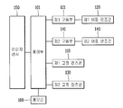
도 1은 본 발명의 실시예에 따른 카메라의 구성요소를 설명하기 위한 구성도이다.
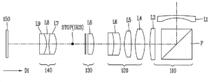
도 2는 도 1의 카메라 모듈의 광학계를 설명하기 위한 개념도이다.
도 3은 본 발명을 설명하기 위한 마스크 픽셀을 나타낸 예시도 이다.
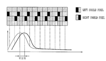
도 4는 본 발명을 설명하기 위한 마스크 픽셀들의 위상차를 나타낸 예시도 이다.
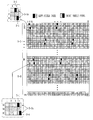
도 5는 본 발명의 실시예에 따른 마스크 픽셀 배열(array)을 나타낸 예시도 이다.
도 6은 본 발명의 다른 실시예에 따른 마스크 픽셀 배열(array)을 나타낸 예시도 이다.
도 7은 본 발명의 또 다른 실시예에 따른 마스크 픽셀 배열(array)을 나타낸 예시도 이다.
도 8은 본 발명의 실시예에 따른 마스크 픽셀의 보간 방법을 나타낸 예시도 이다.1 is a block diagram illustrating components of a camera according to an embodiment of the present invention.
2 is a conceptual diagram for explaining an optical system of the camera module of FIG.
3 is an exemplary view showing a mask pixel for explaining the present invention.
4 is a diagram illustrating an example of a phase difference of mask pixels for explaining the present invention.
5 is an exemplary view illustrating a mask pixel array according to an embodiment of the present invention.
6 is an exemplary view showing a mask pixel array according to another embodiment of the present invention.
7 is an exemplary view showing a mask pixel array according to another embodiment of the present invention.
8 is a diagram illustrating an interpolation method of a mask pixel according to an embodiment of the present invention.
이하, 첨부된 도면을 참조하여 본 명세서에 개시된 실시 예를 상세히 설명하되, 도면 부호에 관계없이 동일하거나 유사한 구성요소는 동일한 참조 번호를 부여하고 이에 대한 중복되는 설명은 생략하기로 한다. 이하의 설명에서 사용되는 구성요소에 대한 접미사 "모듈" 및 "부"는 명세서 작성의 용이함만이 고려되어 부여되거나 혼용되는 것으로서, 그 자체로 서로 구별되는 의미 또는 역할을 갖는 것은 아니다. 또한, 본 명세서에 개시된 실시 예를 설명함에 있어서 관련된 공지 기술에 대한 구체적인 설명이 본 명세서에 개시된 실시 예의 요지를 흐릴 수 있다고 판단되는 경우 그 상세한 설명을 생략한다. 또한, 첨부된 도면은 본 명세서에 개시된 실시 예를 쉽게 이해할 수 있도록 하기 위한 것일 뿐, 첨부된 도면에 의해 본 명세서에 개시된 기술적 사상이 제한되지 않으며, 본 발명의 사상 및 기술 범위에 포함되는 모든 변경, 균등물 내지 대체물을 포함하는 것으로 이해되어야 한다. Hereinafter, embodiments of the present invention will be described in detail with reference to the accompanying drawings, wherein like reference numerals are used to designate identical or similar elements, and redundant description thereof will be omitted. The suffix "module" and " part "for the components used in the following description are given or mixed in consideration of ease of specification, and do not have their own meaning or role. In the following description of the embodiments of the present invention, a detailed description of related arts will be omitted when it is determined that the gist of the embodiments disclosed herein may be blurred. It is to be understood that both the foregoing general description and the following detailed description are exemplary and explanatory and are intended to provide further explanation of the invention as claimed. , ≪ / RTI > equivalents, and alternatives.
제1, 제2 등과 같이 서수를 포함하는 용어는 다양한 구성요소들을 설명하는데 사용될 수 있지만, 상기 구성요소들은 상기 용어들에 의해 한정되지는 않는다. 상기 용어들은 하나의 구성요소를 다른 구성요소로부터 구별하는 목적으로만 사용된다.Terms including ordinals, such as first, second, etc., may be used to describe various elements, but the elements are not limited to these terms. The terms are used only for the purpose of distinguishing one component from another.
어떤 구성요소가 다른 구성요소에 "연결되어" 있다거나 "접속되어" 있다고 언급된 때에는, 그 다른 구성요소에 직접적으로 연결되어 있거나 또는 접속되어 있을 수도 있지만, 중간에 다른 구성요소가 존재할 수도 있다고 이해되어야 할 것이다. 반면에, 어떤 구성요소가 다른 구성요소에 "직접 연결되어" 있다거나 "직접 접속되어" 있다고 언급된 때에는, 중간에 다른 구성요소가 존재하지 않는 것으로 이해되어야 할 것이다.It is to be understood that when an element is referred to as being "connected" or "connected" to another element, it may be directly connected or connected to the other element, . On the other hand, when an element is referred to as being "directly connected" or "directly connected" to another element, it should be understood that there are no other elements in between.
단수의 표현은 문맥상 명백하게 다르게 뜻하지 않는 한, 복수의 표현을 포함한다. The singular expressions include plural expressions unless the context clearly dictates otherwise.
본 출원에서, "포함한다" 또는 "가지다" 등의 용어는 명세서상에 기재된 특징, 숫자, 단계, 동작, 구성요소, 부품 또는 이들을 조합한 것이 존재함을 지정하려는 것이지, 하나 또는 그 이상의 다른 특징들이나 숫자, 단계, 동작, 구성요소, 부품 또는 이들을 조합한 것들의 존재 또는 부가 가능성을 미리 배제하지 않는 것으로 이해되어야 한다.In the present application, the terms "comprises", "having", and the like are used to specify that a feature, a number, a step, an operation, an element, a component, But do not preclude the presence or addition of one or more other features, integers, steps, operations, elements, components, or combinations thereof.
도 1은 본 발명의 실시예에 따른 카메라의 구성요소를 설명하기 위한 구성도이고, 도 2는 도 1의 카메라 모듈의 광학계를 설명하기 위한 개념도이다. FIG. 1 is a block diagram for explaining components of a camera according to an embodiment of the present invention, and FIG. 2 is a conceptual diagram for explaining an optical system of the camera module of FIG.
본 발명의 실시예에 따른 카메라는 순차적으로 배열된 부의 굴절력을 가지는 제1 고정 렌즈군(110), 정의 굴절력을 가지는 제1 이동 렌즈군(120), 정의 굴절력을 가지는 제2 고정 렌즈군(130), 제2 이동 렌즈군(140), 이미지 센서(150), 메모리(160) 중에서 어느 하나 이상을 포함할 수 있다. The camera according to the embodiment of the present invention includes a first
상기 제1 및 제2 이동 렌즈군(120, 140)은 제1 방향(D1)으로 연장되는 광축을 따라 이동하도록 형성된다. 즉, 상기 제1 이동 렌즈군(120)은 제1 구동부(121)와 연결되고, 상기 제2 이동 렌즈군(140)은 상기 제2 구동부(142)와 연결된다.The first and second moving
상기 제1 고정 렌즈군(110)은 제1 렌즈(L1), 제2 렌즈(L2) 및 그 사이에 배치되는 프리즘(prism)로 이루어진다. 구체적으로 상기 제1 고정 렌즈군(110)은 부의 굴절력을 가지는 매니스커스(meniscus)형상의 단식 렌즈의 제1 렌즈(L1), 광로를 약 90도로 전환되도록 형성되는 프리즘(P), 정의 굴절력을 가지는 단식렌즈로 형성되는 제2 렌즈(L1)로 이루어질 수 있다. The first
상기 제1 이동 렌즈군(120)은 제3 내지 제5 렌즈(L3, L4, L5)로 이루어진다. 상기 제2 고정 렌즈군(130)은 제6 렌즈(L6)을 포함하고, 상기 제2 이동 렌즈군(140)은 제7 내지 제9 렌즈(L7, L8, L9)로 이루어진다. 빛은 상기 제1 고정 렌즈군(110), 제1 이동 렌즈군(120), 제2 고정 렌즈군(130) 및 제2 이동 렌즈군(140)을 통과하여 상기 이미지 센서(150)에 도달한다. The first moving
상기 제2 이동 렌즈군(140)의 각 렌즈들 중 적어도 하나는 비구면 렌즈로 형성될 수 있다. 이 경우, 광각단에 있어서 부의 왜곡수차를 보정할 수 있다. At least one of the lenses of the second moving
상기 제1 이동 렌즈군(120) 및 상기 제2 이동 렌즈군(130) 사이에 조리개(IRIS)가 형성된다. 상기 이미지 센서(150) 및 상기 제2 이동 렌즈군(140) 사이에 저역필터(LP, Low Pass Filter), 적외선 커트 필터(Cut Filter) 및 CCD의 커버유리(CG)가 배치될 수 있다. An iris (IRIS) is formed between the first moving
상기 제어부(101)는 상기 제1 및 제2 이동 렌즈군(120, 140)을 이동시켜 주밍(zooming)을 수행한다. 단초점 거리단(광각단)으로부터 장초점 거리단(망원단)으로 변경하는 경우, 상기 제1 이동 렌즈군(120)이 객체가 위치하는 영역으로부터 상면측으로 이동한다. 상기 제어부(101)는 상기 제2 이동 렌즈군(140)를 이동시켜 포커스(focus)를 조정한다. The
상기 제1 및 제2 이동 렌즈군(120, 140)은 상기 제1 및 제2 구동부(121, 141)에 의하여 서로 연동하여 이동할 수 있으나 이에 한정되지 아니하며, 이동하는 방향이 동일하거나 반대될 수 있다. The first and second moving
상기 제1 및 제2 이동 렌즈군(120, 140)과 상기 제1 및 제2 고정 렌즈군(110, 130)을 통과한 빛은 상기 이미지 센서(150)에 도달하여, 초점을 맺은 영상요소들이 변환되어 영상으로 출력된다. Light passing through the first and second
상기 이미지 센서(image sensor)(150)는 1차원 또는 2차원 이상의 광학 정보를 전기적인 영상신호로 변환하는 장치이다. 상기 이미지 센서(150)는 CMOS(complementary metal-oxidesemiconductor)형 또는 CCD(charge coupled device)형의 2종류가 사용될 수 있다. CMOS 이미지 센서는 CMOS 제조 기술을 이용하여 광학적 이미지를 전기적 영상신호로 변환시키는 소자이다.The
상기 이미지 센서(150)는 다수의 픽셀(예를 들면, 다수의 포토 다이오드)을 포함할 수 있으며, 상기 다수의 픽셀은 장시간 노출에 따른 전기적 영상신호(이미지 데이터)를 출력하거나 단시간 노출에 따른 전기적 영상신호(이미지 데이터)를 출력한다.The
상기 이미지 센서(150)는 다수의 픽셀과 다수의 마스크 픽셀을 포함하는 다수의 제1 픽셀 블록과, 다수의 픽셀과 다수의 마스크 픽셀을 포함하는 다수의 제2 픽셀 블록을 포함하며, 상기 제1 픽셀 블록의 다수의 마스크 픽셀의 위치와 상기 제2 픽셀 블록의 다수의 마스크 픽셀의 위치는 서로 다르게 배치된다. 즉, 상기 제2 픽셀 블록의 마스크 픽셀의 위치는 상기 제1 픽셀 블록의 마스크 픽셀의 위치와 동일한 위치가 아닌, 다른 위치에 배치된다. 상기 카메라의 이미지 센서(150)의 제1 픽셀 블록의 마스크 픽셀의 위치와 제2 픽셀 블록의 마스크 픽셀의 위치를 서로 다르게 배치함으로써, 화질의 저하를 최소화하면서 위상차 검출의 정확도를 높일 수 있다. 예를 들면, 상기 제1 픽셀 블록의 마스크 픽셀이 상기 제1 픽셀 블록의 제1행 제1열에 배치되었다고 가정하면, 상기 제2 픽셀 블록의 마스크 픽셀은 상기 제2 픽셀 블록의 제1행 제1열이 아닌 제2행 제2열에 배치된다. 상기 마스크 픽셀이란 위상 검출(Phase Detection)을 위해 일부 광을 차단하는 마스크(예를 들면, 픽셀에 가해지는 광의 1/2을 차단하는 마스크)를 포함하는 픽셀을 의미한다.The
도 3은 본 발명을 설명하기 위한 마스크 픽셀을 나타낸 예시도 이다.3 is an exemplary view showing a mask pixel for explaining the present invention.
도 3에 도시한 바와 같이, 상기 마스크 픽셀은, 광에 노출되는 픽셀(150a, 150b)과, 그 픽셀(150a, 150b) 상에 또는 상부에 형성되어 상기 광의 일부를 차단 또는 반사하는 마스크(3-1)를 포함한다. 상기 마스크(3-1)는 상기 픽셀(150a, 150b)과 마이크로 렌즈(3-2) 사이에 형성될 수 있다.As shown in FIG. 3, the mask pixel includes
상기 이미지 센서(150)의 한 쌍의 픽셀(150a, 150b) 위에 각각 마스크(3-1)를 형성하여 마이크로 렌즈(3-2)를 통해 들어오는 광(빛)을 한 쌍으로 분리할 수 있다. 상기 제어부(101)는 상기 분리된 한 쌍의 광(빛)을 서로 비교함으로써 위상차(phase difference)를 검출하고, 그 검출한 위상차(Phase Difference)를 근거로 초점이 맞았는지를 결정한다. A mask 3-1 may be formed on each of the pair of
도 4는 본 발명을 설명하기 위한 마스크 픽셀들의 위상차를 나타낸 예시도 이다.4 is a diagram illustrating an example of a phase difference of mask pixels for explaining the present invention.
도 4에 도시한 바와 같이, 상기 제어부(101)는 상기 분리된 한 쌍의 광(빛)을 서로 비교함으로써 위상차(phase difference)를 검출하고, 그 검출한 위상차(Phase Difference)를 근거로 초점이 맞았는지를 결정한다. 예를 들면, 상기 제어부(101)는 제1 픽셀(150a)의 우측(또는 좌측)에 형성된 마스크(3-1)를 갖는 제1 픽셀(150a)(Left Shield Pixel)의 광신호와 제2 픽셀(150b)의 좌측(또는 우측)에 형성된 마스크(3-1)를 갖는 제2 픽셀(150b)(Right Shield Pixel)의 광신호의 위상 차를 검출하고, 그 검출한 위상차를 근거로 초점이 맞았는지를 결정한다.As shown in FIG. 4, the
예를 들면, 상기 위상차 검출의 정확도를 높이기 위해서는 다수의 마스크 픽셀이 필요하지만, 이로 인해 화질의 저하를 가져올 수 있다. 마스크 픽셀은 이미지 보간을 통해 복원을 해주어야 하므로, 마스크 픽셀의 수가 많을수록 화질의 저하를 가져올 수 있다. 따라서, 이하에서는, 카메라의 이미지 센서의 제1 픽셀 블록의 마스크 픽셀의 위치와 제2 블록의 마스크 픽셀의 위치를 서로 다르게 배치함으로써, 화질의 저하를 최소화하면서 위상차 검출의 정확도를 높일 수 있는 카메라 및 그 제어 방법을 설명한다. 상기 화질의 저하를 최소화하면서 위상차 검출의 정확도를 높이기 위해 마스크 픽셀을 적절하게 배치할 필요가 있다.For example, in order to increase the accuracy of the phase difference detection, a large number of mask pixels are required, which may result in deterioration of image quality. Since the mask pixel must be restored through image interpolation, the larger the number of mask pixels, the lower the image quality. Therefore, in the following, a camera capable of increasing the accuracy of the phase difference detection while minimizing deterioration of image quality by disposing the position of the mask pixel of the first block and the position of the mask pixel of the second block differently from each other in the image sensor of the camera, and The control method will be described. It is necessary to arrange the mask pixels appropriately in order to increase the accuracy of the phase difference detection while minimizing the degradation of the image quality.
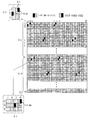
도 5는 본 발명의 실시예에 따른 마스크 픽셀 배열(array)을 나타낸 예시도 이다.5 is an exemplary view illustrating a mask pixel array according to an embodiment of the present invention.
도 5에 도시한 바와 같이, 이미지 센서(150)는 32x64 픽셀로 구성된 다수의 픽셀 블록으로 구성될 수 있다. 상기 32x64 픽셀 블록을 두 개의 제1 및 제2 32x32 서브 블록(5-1, 5-2)으로 분할하고, 상기 제1 32x32 서브 블록(5-1)에 제1 다수의 마스크 픽셀(5-1a)을 배치하고, 상기 제2 32x32 서브 블록(5-2)에 제2 다수의 마스크 픽셀(5-2a)을 배치한다. 상기 제2 다수의 마스크 픽셀(5-2a)은 상기 제1 다수의 마스크 픽셀(5-1a)의 배치 위치와 다르게 배치된다. 예를 들면, 상기 제1 32x32 서브 블록(5-1)의 1행 2열에 제1 마스크 픽셀(5-1a)을 배치했다고 가정할 때, 상기 제2 32x32 서브 블록(5-2)의 1행 2열에도 상기 제1 마스크 픽셀(5-1a)의 위치와 동일하게 제2 마스크 픽셀(5-2a)을 배치하는 것이 아니라, 상기 제2 32x32 서브 블록(5-2)의 1행 4열에 상기 제2 마스크 픽셀(5-2a)을 배치(예를 들면, 2 픽셀 쉬프트(shift)하여 배치)할 수 있다. 즉, 상기 제1 및 제2 마스크 픽셀(5-1a, 5-2a)을 동일한 열이 아닌 서로 다른 열에 배치함으로써 위상차 검출 정확도를 높일 수 있다. 예를 들면, 동일한 열에 두 쌍의 마스크 픽셀을 배치하는 것보다 동일한 열에 한쌍의 마스크 픽셀을 배치함으로써 위상차 검출 정확도를 높일 수 있다. As shown in FIG. 5, the
상기 제1 마스크 픽셀은 좌측(또는 우측)에 형성된 마스크(3-1)를 갖는 제1 픽셀(Left Shield Pixel)일 수 있으며, 상기 제2 마스크 픽셀은 우측(또는 좌측)에 형성된 마스크(3-1)를 갖는 제2 픽셀(Right Shield Pixel)일 수 있다.The first mask pixel may be a left pixel (Left Shield Pixel) having a mask 3-1 formed on the left (or right), and the second mask pixel may be a mask (3- 1 (Right Shield Pixel).
상기 제1 32x32 서브 블록은 하나의 픽셀을 사이에 두고 서로 동일한 제1 열(예를 들면, 2열)에 배치된 한 쌍의 마스크 픽셀을 다수 포함하며,The first 32x32 sub-block includes a plurality of pairs of mask pixels arranged in the same first column (e.g., two columns) with one pixel therebetween,
상기 제2 32x32 서브 블록은 하나의 픽셀을 사이에 두고 서로 동일한 제2 열(예를 들면, 4열)에 배치된 한 쌍의 마스크 픽셀을 다수 포함하며, 상기 제1 열(예를 들면, 2열)과 상기 제2 열(예를 들면, 4열)은 서로 다르다.The second 32x32 sub-block includes a plurality of mask pixels arranged in the same second column (for example, four columns) with one pixel therebetween, and the first column (for example, 2 Column) and the second column (e.g., column 4) are different from each other.
도 6은 본 발명의 다른 실시예에 따른 마스크 픽셀 배열(array)을 나타낸 예시도 이다.6 is an exemplary view showing a mask pixel array according to another embodiment of the present invention.
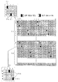
도 6에 도시한 바와 같이, 이미지 센서(150)는 32x64 픽셀로 구성된 다수의 픽셀 블록으로 구성될 수 있다. 상기 32x64 픽셀 블록을 두 개의 제1 및 제2 32x32 서브 블록(6-1, 6-2)으로 분할하고, 상기 제1 32x32 서브 블록(6-1)에 제1 다수의 마스크 픽셀(6-1a)을 배치하고, 상기 제2 32x32 서브 블록(6-2)에 제2 다수의 마스크 픽셀(6-2a)을 배치한다. 상기 제2 다수의 마스크 픽셀(6-2a)은 상기 제1 다수의 마스크 픽셀(6-1a)의 배치 위치와 다르게 배치된다. 예를 들면, 상기 제1 32x32 서브 블록(6-1)의 1행 2열 및 2행 1열에 한 쌍의 제1 마스크 픽셀(6-1a)을 배치했다고 가정할 때, 상기 제2 32x32 서브 블록(6-2)의 1행 2열 및 2행 1열에 한 쌍의 제1 마스크 픽셀(6-1a)의 위치와 동일하게 한 쌍의 제2 마스크 픽셀(6-2a)을 배치하는 것이 아니라, 상기 제2 32x32 서브 블록(6-2)의 1행 4열 및 2행 3열에 상기 제2 마스크 픽셀(6-2a)을 배치(예를 들면, 2 픽셀 쉬프트(shift)하여 배치)할 수 있다. 즉, 상기 제1 및 제2 마스크 픽셀(6-1a, 6-2a)을 동일한 열이 아닌 서로 다른 열에 배치함으로써 위상차 검출 정확도를 높일 수 있다. 예를 들면, 동일한 열에 두 쌍의 마스크 픽셀을 배치하는 것보다 동일한 열에 한쌍의 마스크 픽셀을 배치함으로써 위상차 검출 정확도를 높일 수 있다. As shown in FIG. 6, the
상기 한 쌍의 제1 마스크 픽셀(6-1a)은 우측(또는 좌측)에 형성된 마스크(3-1)를 갖는 제1 픽셀(Right Shield Pixel)과 좌측(또는 우측)에 형성된 마스크(3-1)를 갖는 제2 픽셀(Left Shield Pixel)을 포함할 수 있다. 상기 한 쌍의 제1 마스크 픽셀(6-1a)의 제1 픽셀(Right Shield Pixel)과 제2 픽셀(Left Shield Pixel)은 서로 대각선 방향으로 배치될 수 있다.The pair of first mask pixels 6-1a includes a first pixel (Right Shield Pixel) having a mask 3-1 formed on the right side (or left side) and a first pixel (Right Shield Pixel) formed on the left side (Left Shield Pixel). The first pixel (Right Shield Pixel) and the second pixel (Left Shield Pixel) of the pair of first mask pixels 6-1a may be arranged diagonally with respect to each other.
상기 한 쌍의 제2 마스크 픽셀(6-2a)은 우측(또는 좌측)에 형성된 마스크(3-1)를 갖는 제1 픽셀(Right Shield Pixel)과 좌측(또는 우측)에 형성된 마스크(3-1)를 갖는 제2 픽셀(Left Shield Pixel)을 포함할 수 있다. 상기 한 쌍의 제2 마스크 픽셀(6-2a)의 제1 픽셀(Right Shield Pixel)과 제2 픽셀(Left Shield Pixel)은 서로 대각선 방향으로 배치될 수 있다.The pair of second mask pixels 6-2a includes a first pixel (Right Shield Pixel) having a mask 3-1 formed on the right (or left) and a second pixel (Right Shield Pixel) formed on the left (Left Shield Pixel). The first pixel (Right Shield Pixel) and the second pixel (Left Shield Pixel) of the pair of second mask pixels 6-2a may be arranged diagonally with respect to each other.
상기 제1 32x32 서브 블록은 상기 한 쌍의 마스크 픽셀(6-1a)을 다수 포함하며, 상기 제2 32x32 서브 블록은 상기 한 쌍의 마스크 픽셀(6-2a)을 다수 포함할 수 있다.The first 32x32 sub-block may include a plurality of the mask pixels 6-1a, and the second 32x32 sub-block may include a plurality of the mask pixels 6-2a.
도 7은 본 발명의 또 다른 실시예에 따른 마스크 픽셀 배열(array)을 나타낸 예시도 이다.7 is an exemplary view showing a mask pixel array according to another embodiment of the present invention.
도 7에 도시한 바와 같이, 이미지 센서(150)는 32x64 픽셀로 구성된 다수의 픽셀 블록으로 구성될 수 있다. 상기 32x64 픽셀 블록을 두 개의 제1 및 제2 32x32 서브 블록(7-1, 7-2)으로 분할하고, 상기 제1 32x32 서브 블록(7-1)에 제1 다수의 마스크 픽셀(7-1a)을 배치하고, 상기 제2 32x32 서브 블록(7-2)에 제2 다수의 마스크 픽셀(7-2a)을 배치한다. 상기 제2 다수의 마스크 픽셀(7-2a)은 상기 제1 다수의 마스크 픽셀(7-1a)의 배치 위치와 다르게 배치된다. 예를 들면, 상기 제1 32x32 서브 블록(7-1)의 1행 1열 및 4행 2열에 한 쌍의 제1 마스크 픽셀(7-1a)을 배치했다고 가정할 때, 상기 제2 32x32 서브 블록(7-2)의 1행 1열 및 4행 2열에 한 쌍의 제1 마스크 픽셀(7-1a)의 위치와 동일하게 한 쌍의 제2 마스크 픽셀(7-2a)을 배치하는 것이 아니라, 상기 제2 32x32 서브 블록(7-2)의 1행 3열 및 4행 4열에 상기 제2 마스크 픽셀(7-2a)을 배치(예를 들면, 2 픽셀 쉬프트(shift)하여 배치)할 수 있다. 즉, 상기 제1 및 제2 마스크 픽셀(7-1a, 7-2a)을 동일한 행과 열이 아닌 서로 다른 행과 열에 배치함으로써 위상차 검출 정확도를 높일 수 있다. 예를 들면, 동일한 행과 열에 두 쌍의 마스크 픽셀을 배치하는 것보다 동일한 행과 열에 한쌍의 마스크 픽셀을 배치함으로써 위상차 검출 정확도를 높일 수 있다. As shown in FIG. 7, the
상기 한 쌍의 제1 마스크 픽셀(7-1a)은 좌측(또는 우측)에 형성된 마스크(3-1)를 갖는 제1 픽셀(Left Shield Pixel)과 좌측(또는 우측)에 형성된 마스크(3-1)를 갖는 제2 픽셀(Right Shield Pixel)을 포함할 수 있다. 상기 한 쌍의 제1 마스크 픽셀(7-1a)의 제1 픽셀(Left Shield Pixel)과 제2 픽셀(Right Shield Pixel)은 두개의 픽셀을 사이에 두고 서로 대각선 방향으로 배치될 수 있다.The pair of first mask pixels 7-1a includes a first pixel (Left Shield Pixel) having a mask 3-1 formed on the left (or right) and a second pixel (Left Shield Pixel) formed on the left (Right Shield Pixel). The first pixel (Left Shield Pixel) and the second pixel (Right Shield Pixel) of the pair of first mask pixels 7-1a may be arranged in a diagonal direction with two pixels sandwiched therebetween.
상기 한 쌍의 제2 마스크 픽셀(7-2a)은 좌측(또는 우측)에 형성된 마스크(3-1)를 갖는 제1 픽셀(Left Shield Pixel)과 좌측(또는 우측)에 형성된 마스크(3-1)를 갖는 제2 픽셀(Right Shield Pixel)을 포함할 수 있다. 상기 한 쌍의 제2 마스크 픽셀(7-2a)의 제1 픽셀(Left Shield Pixel)과 제2 픽셀(Right Shield Pixel)은 두개의 픽셀을 사이에 두고 서로 대각선 방향으로 배치될 수 있다.The pair of second mask pixels 7-2a includes a first pixel (Left Shield Pixel) having a mask 3-1 formed on the left (or right) and a second pixel (Left Shield Pixel) formed on the left (Right Shield Pixel). The first pixel (Left Shield Pixel) and the second pixel (Right Shield Pixel) of the pair of second mask pixels 7-2a may be arranged in a diagonal direction with two pixels sandwiched therebetween.
상기 제1 32x32 서브 블록은 상기 한 쌍의 마스크 픽셀(7-1a)을 다수 포함하며, 상기 제2 32x32 서브 블록은 상기 한 쌍의 마스크 픽셀(7-2a)을 다수 포함할 수 있다.The first 32x32 sub-block may include a plurality of the mask pixels 7-1a, and the second 32x32 sub-block may include a plurality of the mask pixels 7-2a.
이하에서는, 상기 마스크 픽셀을 보간(interpolation)하는 방법을 설명한다. 예를 들면, 위상차를 구하기 위해 배치된 마스크 픽셀들은 정상 픽셀에 비해 광량이 절반 이하로 줄어듦으로 인해 화질의 열화를 발생한다. 따라서, 마스크 픽셀의 화소값을 보간(복원)함으로써 화질의 저하를 최소화할 수 있다.Hereinafter, a method of interpolating the mask pixels will be described. For example, the mask pixels arranged to obtain the phase difference cause image quality deterioration due to a reduction in the amount of light less than half that of a normal pixel. Therefore, the degradation of image quality can be minimized by interpolating (restoring) the pixel value of the mask pixel.
도 8은 본 발명의 실시예에 따른 마스크 픽셀의 보간 방법을 나타낸 예시도 이다.8 is a diagram illustrating an interpolation method of a mask pixel according to an embodiment of the present invention.
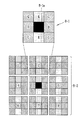
도 8에 도시한 바와 같이, 상기 제어부(101)는 상기 마스크 픽셀(8-1a)을 갖는 블록을 기준 블록(8-1)으로 설정하고, 상기 기준 블록(8-1)과, 그 기준 블록(8-1)의 주변의 블록들(8-2)의 각 SAD(sum average difference) 값을 구한다.8, the
상기 제어부(101)는 상기 주변의 블록들(8-2)의 SAD 값들 중에서 상기 기준 블록(8-1)의 SAD 값과 가장 근접(유사)한 값을 갖는 블록의 화소 값을 근거로 상기 기준 블록의 화소값을 복원할 수도 있다. 예를 들면, 상기 제어부(101)는 G(Green) 픽셀이 아닌 3x3 블록 내의 R(red), B(blue) 픽셀을 이용하여 에지(edge)를 조사하여 마스크 픽셀(8-1a)을 갖는 기준 블록(8-1)의 SAD 값과 그 기준 블록(8-1)의 주변 8개의 블록들(8-2)의 SAD(sum average difference) 값을 구한다. 상기 제어부(101)는 상기 주변 블록(8-1)의 SAD 값이 작으면 상기 주변 블록(8-1)이 상기 기준 블록(8-1)과 유사한 블록인 것으로 결정할 수도 있다. The
상기 제어부(101)는 상기 주변 블록들(8-2)의 각 SAD 값들에 반비례하는 가중치(weight)를 상기 각 SAD 값에 적용하고, 그 가중치가 적용된 SAD 값들 중에서 상기 기준 블록(8-1)의 SAD 값과 동일 또는 유사한 값을 갖는 블록의 화소 값을 근거로 상기 기준 블록(8-1)의 화소값을 복원할 수도 있다. 예를 들면, 상기 제어부(101)는 상기 주변 블록들(8-2) 중에서 제1 블록의 SAD 값이 크면 그 제1 블록의 SAD 값에 작은 가중치(weight) 적용하고, 상기 주변 블록들(8-2) 중에서 제2 블록의 SAD 값이 크면 그 제2 블록의 SAD 값에 큰 가중치(weight)를 적용할 수도 있다. The
상기 제어부(101)는 상기 마스크 픽셀의 복원값(화소값)(![]()
![]()
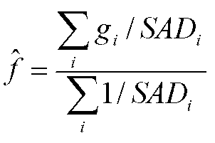
여기서, ![]()
![]()
![]()
![]()
![]()
![]()
이상에서 설명한 바와 같이, 본 발명의 실시예에 따른 카메라 및 그 제어 방법은, 카메라의 이미지 센서의 제1 픽셀 블록의 마스크 픽셀의 위치와 제2 블록의 마스크 픽셀의 위치를 서로 다르게 배치함으로써, 화질의 저하를 최소화하면서 위상차 검출의 정확도를 높일 수 있다.As described above, according to the camera and the control method thereof according to the embodiment of the present invention, the position of the mask pixel of the first pixel block and the position of the mask pixel of the second block of the image sensor of the camera are arranged differently, The accuracy of the phase difference detection can be increased while minimizing the deterioration of the phase difference.
또한, 본 명세서에 개시된 일 실시 예에 의하면, 전술한 방법은, 프로그램이 기록된 매체에 프로세서가 읽을 수 있는 코드로서 구현하는 것이 가능하다. 프로세서가 읽을 수 있는 매체의 예로는, ROM, RAM, cd-ROM, 자기 테이프, 플로피 디스크, 광 데이터 저장장치 등이 있으며, 캐리어 웨이브(예를 들어, 인터넷을 통한 전송)의 형태로 구현되는 것도 포함한다.Further, according to the embodiment disclosed herein, the above-described method can be implemented as a code that can be read by a processor on a medium on which the program is recorded. Examples of the medium that can be read by the processor include ROM, RAM, CD-ROM, magnetic tape, floppy disk, optical data storage, etc., and may be implemented in the form of a carrier wave (e.g., transmission over the Internet) .
한편 상술한 본 발명의 설명에서는 구체적인 실시 예에 관해 설명하였으나, 여러 가지 변형이 본 발명의 범위에서 벗어나지 않고 실시할 수 있다. 특히 본 발명의 실시 예에서는 마스크 픽셀의 배치 구조를 언급하였으나, 얼마든지 다양한 형태의 배치 구조가 사용될 수 있음은 물론이다. While the invention has been shown and described with reference to certain preferred embodiments thereof, it will be understood by those skilled in the art that various changes and modifications may be made without departing from the spirit and scope of the invention. In particular, although the embodiments of the present invention have been described with reference to the arrangement structure of the mask pixels, it is needless to say that various arrangements can be used.
이처럼 본 발명이 속하는 기술 분야에서 통상의 지식을 가진 자라면 본 발명의 본질적인 특성에서 벗어나지 않는 범위에서 다양한 수정 및 변형이 가능할 것이다. 따라서 본 발명에 개시된 실시 예들은 본 발명의 기술 사상을 한정하기 위한 것이 아니라 설명하기 위한 것이고, 이러한 실시 예에 의하여 본 발명의 기술 사상의 범위가 한정되는 것은 아니다. 본 발명의 보호 범위는 아래의 청구범위에 의하여 해석 되어야 하며, 그와 동등한 범위 내에 있는 모든 기술 사상은 본 발명의 권리범위에 포함되는 것으로 해석되어야 할 것이다.It will be apparent to those skilled in the art that various modifications and variations can be made in the present invention without departing from the essential characteristics thereof. Therefore, the embodiments disclosed in the present invention are not intended to limit the scope of the present invention but to limit the scope of the technical idea of the present invention. The scope of protection of the present invention should be construed according to the following claims, and all technical ideas within the scope of equivalents should be construed as falling within the scope of the present invention.
Claims (10)
상기 제1 마스크 픽셀의 제1 광신호와 상기 제2 마스크 픽셀의 제2 광신호의 위상 차를 검출하고, 상기 검출한 위상 차를 근거로 카메라의 초점을 제어하는 제어부를 포함하며,
상기 제2 마스크 픽셀은 상기 제1 마스크 픽셀의 위치와는 다른 위치에 배치되는 것을 특징으로 하는 카메라.An image sensor including a first pixel block including a first pixel and a first mask pixel, and a second pixel block including a second pixel and a second mask pixel;
And a control unit for detecting a phase difference between the first optical signal of the first mask pixel and the second optical signal of the second mask pixel and controlling the focus of the camera based on the detected phase difference,
Wherein the second mask pixel is disposed at a position different from a position of the first mask pixel.
상기 제1 픽셀 블록 내의 상기 제1 마스크 픽셀의 배치 위치와 상기 제2 픽셀 블록 내의 상기 제2 마스크 픽셀의 배치 위치는 서로 다른 것을 특징으로 하는 카메라.The method according to claim 1,
Wherein a placement position of the first mask pixel in the first pixel block and a placement position of the second mask pixel in the second pixel block are different from each other.
하나의 픽셀과;
상기 하나의 픽셀에 인가되는 광의 일부를 차단하는 마스크를 포함하는 것을 특징으로 하는 카메라.2. The apparatus of claim 1, wherein each of the first and second mask pixels comprises:
One pixel;
And a mask for blocking a part of light applied to the one pixel.
상기 제2 픽셀 블록은 하나의 픽셀을 사이에 두고 서로 동일한 제2 열에 배치된 한 쌍의 마스크 픽셀을 다수 포함하며, 상기 제1 열과 상기 제2 열은 서로 다른 것을 특징으로 하는 카메라.2. The image pickup apparatus according to claim 1, wherein the first pixel block includes a plurality of mask pixels arranged in the same first column with one pixel therebetween,
Wherein the second pixel block includes a plurality of mask pixels arranged in the same second column with one pixel therebetween, wherein the first column and the second column are different from each other.
상기 제2 픽셀 블록은 대각선 방향으로 제3 행 및 제3 열과 제4행 및 제4열에 각각 배치된 한 쌍의 마스크 픽셀을 다수 포함하는 것을 특징으로 하는 카메라.2. The image pickup apparatus according to claim 1, wherein the first pixel block includes a plurality of mask pixels arranged in a first row and a first column and a second row and a second column in a diagonal direction, respectively,
Wherein the second pixel block includes a plurality of mask pixels arranged in a third row and a third column in a diagonal direction, and a pair of mask pixels arranged in a fourth row and a fourth column, respectively.
상기 제2 픽셀 블록은 두 개의 픽셀을 사이에 두고 대각선 방향으로 제3 행 및 제3 열과 제4행 및 제4열에 각각 배치된 한 쌍의 마스크 픽셀을 다수 포함하는 것을 특징으로 하는 카메라.2. The liquid crystal display according to claim 1, wherein the first pixel block includes a plurality of pairs of mask pixels arranged in a first row and a first column and a second row and a second column, respectively, in a diagonal direction with two pixels therebetween,
Wherein the second pixel block includes a plurality of mask pixels arranged in a third row and a third column and in a fourth row and a fourth column, respectively, in a diagonal direction with two pixels therebetween.
상기 제1 마스크 픽셀을 갖는 픽셀 블록을 기준 블록으로 설정하고, 상기 기준 블록의 SAD(sum average difference) 값과, 상기 기준 블록의 주변의 블록들의 SAD 값들을 구하고, 상기 주변의 블록들의 SAD 값들 중에서 상기 기준 블록의 SAD 값과 가장 근접한 SAD 값을 갖는 블록의 화소 값을 근거로 상기 기준 블록의 화소값을 복원하는 것을 특징으로 하는 카메라.The apparatus of claim 1,
Setting a pixel block having the first mask pixel as a reference block, calculating a sum average difference (SAD) value of the reference block and SAD values of neighboring blocks of the reference block, And restores the pixel value of the reference block based on the pixel value of the block having the SAD value closest to the SAD value of the reference block.
상기 제1 마스크 픽셀을 갖는 픽셀 블록을 기준 블록으로 설정하고, 상기 기준 블록의 SAD(sum average difference) 값과, 상기 기준 블록의 주변의 블록들의 SAD 값들을 구하고, 상기 주변 블록들의 각 SAD 값들에 반비례하는 가중치를 상기 주변 블록들의 각 SAD 값에 적용하고, 상기 가중치가 적용된 SAD 값들 중에서 상기 기준 블록의 SAD 값과 가장 근접한 SAD 값을 갖는 블록의 화소 값을 근거로 상기 기준 블록의 화소값을 복원하는 것을 특징으로 하는 카메라.The apparatus of claim 1,
Setting a pixel block having the first mask pixel as a reference block, calculating a sum average difference (SAD) value of the reference block and SAD values of neighboring blocks of the reference block, The inverse weight is applied to each SAD value of the neighboring blocks and the pixel value of the reference block is restored based on the pixel value of the block having the SAD value closest to the SAD value of the reference block among the weighted SAD values And a camera.
상기 제1 마스크 픽셀의 제1 광신호와 상기 제2 마스크 픽셀의 제2 광신호의 위상 차를 검출하고, 상기 검출한 위상 차를 근거로 카메라의 초점을 제어하는 단계를 포함하며, 상기 제2 마스크 픽셀은 상기 제1 마스크 픽셀의 위치와는 다른 위치에 배치되는 것을 특징으로 하는 카메라의 제어 방법.A control method of a camera having an image sensor including a first pixel block including a first pixel and a first mask pixel and a second pixel block including a second pixel and a second mask pixel,
Detecting a phase difference between a first optical signal of the first mask pixel and a second optical signal of the second mask pixel and controlling the focus of the camera based on the detected phase difference, Wherein the mask pixel is disposed at a position different from the position of the first mask pixel.
Priority Applications (1)
| Application Number | Priority Date | Filing Date | Title |
|---|---|---|---|
| KR1020150088556A KR20160150488A (en) | 2015-06-22 | 2015-06-22 | Camera and control method thereof |
Applications Claiming Priority (1)
| Application Number | Priority Date | Filing Date | Title |
|---|---|---|---|
| KR1020150088556A KR20160150488A (en) | 2015-06-22 | 2015-06-22 | Camera and control method thereof |
Publications (1)
| Publication Number | Publication Date |
|---|---|
| KR20160150488A true KR20160150488A (en) | 2016-12-30 |
Family
ID=57737277
Family Applications (1)
| Application Number | Title | Priority Date | Filing Date |
|---|---|---|---|
| KR1020150088556A Withdrawn KR20160150488A (en) | 2015-06-22 | 2015-06-22 | Camera and control method thereof |
Country Status (1)
| Country | Link |
|---|---|
| KR (1) | KR20160150488A (en) |
-
2015
- 2015-06-22 KR KR1020150088556A patent/KR20160150488A/en not_active Withdrawn
Similar Documents
| Publication | Publication Date | Title |
|---|---|---|
| KR102398667B1 (en) | Image sensor including phase detection pixel | |
| JP5012495B2 (en) | IMAGING ELEMENT, FOCUS DETECTION DEVICE, FOCUS ADJUSTMENT DEVICE, AND IMAGING DEVICE | |
| US9267797B2 (en) | Range-finding device and imaging apparatus | |
| US9196644B2 (en) | Imaging device for phase difference detection for focusing and image generation | |
| CN103874952B (en) | Solid-state imaging element, imaging device, and focusing control method | |
| JP4818957B2 (en) | Imaging apparatus and method thereof | |
| US12197106B2 (en) | Image sensor and image-capturing device that selects pixel signal for focal position | |
| US8369700B2 (en) | Distance measurement and photometry device, and imaging apparatus | |
| EP3354017A1 (en) | Mask-less phase detection autofocus | |
| US9001260B2 (en) | Imaging apparatus and imaging method | |
| KR20110074291A (en) | Zoom lens and photographing device having the same | |
| TW201544855A (en) | Wafer-level camera with a movable color filter group | |
| KR20130104756A (en) | Image apparatus and image sensor thereof | |
| JP2011114788A5 (en) | ||
| JP2024091768A (en) | Image sensor and image pickup device | |
| CN104580950A (en) | Compact spacer in multi-lens array module | |
| TWI842268B (en) | Image system with on-chip occlusion detection and related non-transitory machine-accessible storage medium | |
| EP2763400B1 (en) | Imaging element, and imaging device | |
| JP5228777B2 (en) | Focus detection apparatus and imaging apparatus | |
| KR20160143138A (en) | Camera and control method thereof | |
| US20200092489A1 (en) | Optical apparatus, control method, and non-transitory computer-readable storage medium | |
| KR20160150488A (en) | Camera and control method thereof | |
| US7812296B2 (en) | Imaging apparatus and method for generating an aberration free image | |
| JP5665402B2 (en) | Imaging system and control method thereof | |
| JP2014186227A (en) | Imaging device, control method of the same and control program |
Legal Events
| Date | Code | Title | Description |
|---|---|---|---|
| PA0109 | Patent application |
Patent event code: PA01091R01D Comment text: Patent Application Patent event date: 20150622 |
|
| PG1501 | Laying open of application | ||
| PC1203 | Withdrawal of no request for examination |