KR20160132505A - A outdoor light - Google Patents
A outdoor light Download PDFInfo
- Publication number
- KR20160132505A KR20160132505A KR1020150065085A KR20150065085A KR20160132505A KR 20160132505 A KR20160132505 A KR 20160132505A KR 1020150065085 A KR1020150065085 A KR 1020150065085A KR 20150065085 A KR20150065085 A KR 20150065085A KR 20160132505 A KR20160132505 A KR 20160132505A
- Authority
- KR
- South Korea
- Prior art keywords
- top cover
- led
- cover
- side cover
- space
- Prior art date
Links
Images

Classifications
-
- F—MECHANICAL ENGINEERING; LIGHTING; HEATING; WEAPONS; BLASTING
- F21—LIGHTING
- F21V—FUNCTIONAL FEATURES OR DETAILS OF LIGHTING DEVICES OR SYSTEMS THEREOF; STRUCTURAL COMBINATIONS OF LIGHTING DEVICES WITH OTHER ARTICLES, NOT OTHERWISE PROVIDED FOR
- F21V14/00—Controlling the distribution of the light emitted by adjustment of elements
-
- F—MECHANICAL ENGINEERING; LIGHTING; HEATING; WEAPONS; BLASTING
- F21—LIGHTING
- F21K—NON-ELECTRIC LIGHT SOURCES USING LUMINESCENCE; LIGHT SOURCES USING ELECTROCHEMILUMINESCENCE; LIGHT SOURCES USING CHARGES OF COMBUSTIBLE MATERIAL; LIGHT SOURCES USING SEMICONDUCTOR DEVICES AS LIGHT-GENERATING ELEMENTS; LIGHT SOURCES NOT OTHERWISE PROVIDED FOR
- F21K9/00—Light sources using semiconductor devices as light-generating elements, e.g. using light-emitting diodes [LED] or lasers
-
- F—MECHANICAL ENGINEERING; LIGHTING; HEATING; WEAPONS; BLASTING
- F21—LIGHTING
- F21V—FUNCTIONAL FEATURES OR DETAILS OF LIGHTING DEVICES OR SYSTEMS THEREOF; STRUCTURAL COMBINATIONS OF LIGHTING DEVICES WITH OTHER ARTICLES, NOT OTHERWISE PROVIDED FOR
- F21V15/00—Protecting lighting devices from damage
- F21V15/01—Housings, e.g. material or assembling of housing parts
- F21V15/015—Devices for covering joints between adjacent lighting devices; End coverings
-
- F—MECHANICAL ENGINEERING; LIGHTING; HEATING; WEAPONS; BLASTING
- F21—LIGHTING
- F21V—FUNCTIONAL FEATURES OR DETAILS OF LIGHTING DEVICES OR SYSTEMS THEREOF; STRUCTURAL COMBINATIONS OF LIGHTING DEVICES WITH OTHER ARTICLES, NOT OTHERWISE PROVIDED FOR
- F21V17/00—Fastening of component parts of lighting devices, e.g. shades, globes, refractors, reflectors, filters, screens, grids or protective cages
- F21V17/10—Fastening of component parts of lighting devices, e.g. shades, globes, refractors, reflectors, filters, screens, grids or protective cages characterised by specific fastening means or way of fastening
- F21V17/16—Fastening of component parts of lighting devices, e.g. shades, globes, refractors, reflectors, filters, screens, grids or protective cages characterised by specific fastening means or way of fastening by deformation of parts; Snap action mounting
-
- F—MECHANICAL ENGINEERING; LIGHTING; HEATING; WEAPONS; BLASTING
- F21—LIGHTING
- F21V—FUNCTIONAL FEATURES OR DETAILS OF LIGHTING DEVICES OR SYSTEMS THEREOF; STRUCTURAL COMBINATIONS OF LIGHTING DEVICES WITH OTHER ARTICLES, NOT OTHERWISE PROVIDED FOR
- F21V29/00—Protecting lighting devices from thermal damage; Cooling or heating arrangements specially adapted for lighting devices or systems
- F21V29/50—Cooling arrangements
- F21V29/70—Cooling arrangements characterised by passive heat-dissipating elements, e.g. heat-sinks
-
- F—MECHANICAL ENGINEERING; LIGHTING; HEATING; WEAPONS; BLASTING
- F21—LIGHTING
- F21W—INDEXING SCHEME ASSOCIATED WITH SUBCLASSES F21K, F21L, F21S and F21V, RELATING TO USES OR APPLICATIONS OF LIGHTING DEVICES OR SYSTEMS
- F21W2131/00—Use or application of lighting devices or systems not provided for in codes F21W2102/00-F21W2121/00
- F21W2131/10—Outdoor lighting
Abstract
Description
The present invention relates to an outdoor lighting device, and more particularly, to an outdoor lighting device, and more particularly, to an outdoor lighting device, and more particularly, Lt; / RTI >
As is well known, the floodlight is installed indoors or outdoors so that light of desired brightness can be inspected in architectural structures, large monuments, various stadiums, various factory facilities, and industrial facilities. These floodlights are mainly made of high-intensity discharge lamps. The surface where the light is projected is made of glass or acrylic, which is excellent in transmittance. It is installed at an optimal position for enhancing the lighting effect, They are arranged at proper intervals and projected in a desired direction.
Metal halide lamps such as metal halide lamps and sodium lamps, such as halogen lamps, are used as light sources used for such light projections. These lamps require a large amount of electric power, short service life, and long lighting time. And pollute the environment.
Therefore, recently, LEDs which require low power consumption and have semi-permanent lifespan characteristics are widely applied as light sources in terms of illumination improvement and energy saving.
A light emitting diode (LED), a light emitting diode (LED), a light emitting diode (LED), a light emitting diode (LED), a light emitting diode And a heat sink attached to the back surface of the top cover to cool the heat generated by the LED.
On both sides of the top cover, a mounting frame for fixing the illumination lamp to the floor, ceiling or wall surface is installed. At this time, the mounting frame and the top cover are bolted to each other while being in surface contact with each other, There is a disadvantage that it is difficult to adjust the angle of the user's desired angle by slipping the mounting frame in the top cover in the process of tilting the top cover.
In addition, there is a problem that rainwater seeps through the fastening holes to which the bolts are fastened when raining, thereby damaging electrical parts such as a substrate.
SUMMARY OF THE INVENTION Accordingly, the present invention has been made keeping in mind the above problems occurring in the prior art, and it is an object of the present invention to provide an apparatus and a method for adjusting the angle of a top cover that emits light, Provide outdoor lighting to be able to.
According to an aspect of the present invention, there is provided an outdoor lighting comprising: a top cover having a receiving space formed therein; a printed circuit board accommodated in an inner space of the top cover and equipped with an LED for emitting light; A heat radiating plate which is closely attached to the substrate and heat-exchanges heat generated from the LED, a side cover provided on both sides of the top cover, a connecting cap connected to the side cover by an axial pin, and an arm removably assembled to the connecting cap, Wherein a gear is formed on the outer surface of the side cover and a gear for engaging with the gear is formed on an inner surface of the connection cap so as to rotate around the shaft pin, And the top cover is fixed without slip.
The upper surface of the heat sink may include a heat radiation box having a space therein, and the space of the heat radiation box may be filled with silicon.
It is preferable that an insertion groove is formed in the front and rear of the receiving space of the top cover, and protrusions inserted in the insertion groove are protruded from the front and rear sides of the heat radiating plate.
In the present invention, a connection cap connected to an arm of a mounting frame for emitting light and a gear engaged with the side cover of the top cover are respectively formed. When the top cover is rotated, the gears are engaged with each other, After the angle is adjusted by supporting the cover, the top cover does not slip on the mounting frame due to its own weight, and has the effect of continuously maintaining the angle-controlled state.
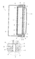
BRIEF DESCRIPTION OF THE DRAWINGS Fig. 1 is an exploded perspective view of an outdoor lighting system according to the present invention; Fig.
2 is a cross-sectional view of an outdoor lighting according to the present invention.
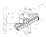
Fig. 3 shows a state in which the angle of the LED is adjusted. Fig.
Hereinafter, embodiments of the present invention will be described with reference to the accompanying drawings. In the following detailed description, exemplary embodiments of the present invention will be described in order to accomplish the above-mentioned technical problems. And other embodiments which may be presented by the present invention are replaced by descriptions in the constitution of the present invention.
FIG. 2 is a cross-sectional view of an outdoor lighting according to the present invention. FIG. 3 is a view showing a state in which an angle of an LED is adjusted, and FIG. Fig.
1 to 3, the
The LED (Light Emitting Diode) 12 is mounted on the printed
The
An insertion groove 24 is formed in the front and rear of the
When the
The
When the
A
The
A
The
The
The connecting
After the angle of the
Hereinafter, the operation of the outdoor lighting according to the present invention will be described with reference to FIGS. 1 to 3 attached hereto.
The assembly of the
Meanwhile, in order to adjust the angle of illumination in the course of using the outdoor lighting, when the
10: printed circuit board 12: LED
20: top cover 22: accommodation space
24: insertion groove 30: side cover
32: Hole 34: Gear
40: heat sink 42:
46: space 48: fastener
49: projection 50: mounting frame
52: arm 54: connecting hole
60: connection cap 62: space
64: hole 66: gear
70: Pivot pin
Claims (3)
A top cover (20) having a receiving space (22) formed therein;
A printed circuit board (10) accommodated in an internal space (22) of the top cover (20) and equipped with an LED (12) emitting light;
A heat sink (30) which is in close contact with the printed circuit board (10) and exchanges heat generated by the LED (12);
Side covers (40) provided on both sides of the top cover (20);
A connection cap 60 coupled to the side cover 40 by an axial pin 70;
And a mounting frame (50) having an arm (52) detachably assembled to the connecting cap (60) and for receiving the top cover (20) for use;
A gear 34 is formed on the outer surface of the side cover 30 and a gear 66 for engaging the gear 34 is formed on the inner surface of the connection cap 60, So as to fix the top cover (20), which is rotating and whose angle is adjusted, without slip.
Wherein a heat dissipation box (44) having a space (46) is provided in an upper surface of the heat dissipation plate (40), and a silicon (80) is filled in a space of the heat dissipation box (44).
An insertion groove 24 is formed in the front and rear of the housing space 22 of the top cover 20. A protrusion 49 inserted into the insertion groove 24 is formed at the front and rear of the lower surface of the heat sink 40 And the projecting portion is formed in a projecting shape.
Priority Applications (1)
| Application Number | Priority Date | Filing Date | Title |
|---|---|---|---|
| KR1020150065085A KR101743818B1 (en) | 2015-05-11 | 2015-05-11 | A outdoor light |
Applications Claiming Priority (1)
| Application Number | Priority Date | Filing Date | Title |
|---|---|---|---|
| KR1020150065085A KR101743818B1 (en) | 2015-05-11 | 2015-05-11 | A outdoor light |
Publications (2)
| Publication Number | Publication Date |
|---|---|
| KR20160132505A true KR20160132505A (en) | 2016-11-21 |
| KR101743818B1 KR101743818B1 (en) | 2017-06-05 |
Family
ID=57537936
Family Applications (1)
| Application Number | Title | Priority Date | Filing Date |
|---|---|---|---|
| KR1020150065085A KR101743818B1 (en) | 2015-05-11 | 2015-05-11 | A outdoor light |
Country Status (1)
| Country | Link |
|---|---|
| KR (1) | KR101743818B1 (en) |
Cited By (1)
| Publication number | Priority date | Publication date | Assignee | Title |
|---|---|---|---|---|
| CN107255239A (en) * | 2017-07-10 | 2017-10-17 | 深圳福凯半导体技术股份有限公司 | Illuminating lamp |
Citations (2)
| Publication number | Priority date | Publication date | Assignee | Title |
|---|---|---|---|---|
| KR101173921B1 (en) | 2012-03-22 | 2012-08-14 | 케이디지전자 주식회사 | Led flood light |
| KR101211186B1 (en) | 2012-02-06 | 2012-12-12 | 주식회사 세종엔진 | Led flood lamp including detachable gasket |
Family Cites Families (2)
| Publication number | Priority date | Publication date | Assignee | Title |
|---|---|---|---|---|
| JP4797970B2 (en) * | 2006-12-22 | 2011-10-19 | パナソニック電工株式会社 | LED lighting device |
| KR101075368B1 (en) * | 2011-03-17 | 2011-11-03 | 주식회사 파인테크닉스 | The flood lighting capable of adjustable angle individual |
-
2015
- 2015-05-11 KR KR1020150065085A patent/KR101743818B1/en active IP Right Grant
Patent Citations (2)
| Publication number | Priority date | Publication date | Assignee | Title |
|---|---|---|---|---|
| KR101211186B1 (en) | 2012-02-06 | 2012-12-12 | 주식회사 세종엔진 | Led flood lamp including detachable gasket |
| KR101173921B1 (en) | 2012-03-22 | 2012-08-14 | 케이디지전자 주식회사 | Led flood light |
Cited By (3)
| Publication number | Priority date | Publication date | Assignee | Title |
|---|---|---|---|---|
| CN107255239A (en) * | 2017-07-10 | 2017-10-17 | 深圳福凯半导体技术股份有限公司 | Illuminating lamp |
| WO2019010852A1 (en) * | 2017-07-10 | 2019-01-17 | 深圳福凯半导体技术股份有限公司 | Illumination lamp |
| US10648656B2 (en) | 2017-07-10 | 2020-05-12 | Ledlucky Holdings Company Ltd. | Floodlight |
Also Published As
| Publication number | Publication date |
|---|---|
| KR101743818B1 (en) | 2017-06-05 |
Similar Documents
| Publication | Publication Date | Title |
|---|---|---|
| US8506127B2 (en) | Lens frame with a LED support surface and heat dissipating structure | |
| AU2009298917B2 (en) | Lighting apparatus with heat dissipation system | |
| CA2815067C (en) | Reflectors and reflector orientation feature to prevent non-qualified trim | |
| KR200479421Y1 (en) | easy heat release spherical lighting | |
| MX2011006047A (en) | Adjustable slope ceiling recessed light fixture. | |
| CN106461165A (en) | Thermally dissipated lighting system | |
| KR20170000589A (en) | LED landscape lighting device | |
| KR101102455B1 (en) | LED Lamp | |
| TW201326642A (en) | LED street lamp | |
| JP2013004249A (en) | Lighting fixture | |
| KR200407799Y1 (en) | Floodlight | |
| KR101743818B1 (en) | A outdoor light | |
| KR101426293B1 (en) | Housing for flood light | |
| KR100576682B1 (en) | Floodlight | |
| JP6264099B2 (en) | lighting equipment | |
| KR200410556Y1 (en) | Floodlight | |
| KR101608972B1 (en) | head for LED streetlight | |
| JP6433016B2 (en) | Large light LED floodlight | |
| KR20170074515A (en) | LED Floodlight Reflector replacement easy | |
| KR20150133669A (en) | assembly efficiency lighting device | |
| KR101012820B1 (en) | Lighting apparatus having high thermal radiation | |
| RU120481U1 (en) | LED LAMP | |
| KR101587834B1 (en) | Lamp For Outdoor | |
| JP6287346B2 (en) | lighting equipment | |
| AU2013205909B2 (en) | Lighting Apparatus With Heat Dissipation System |
Legal Events
| Date | Code | Title | Description |
|---|---|---|---|
| A201 | Request for examination | ||
| E902 | Notification of reason for refusal | ||
| E701 | Decision to grant or registration of patent right |