KR20160128126A - Moving robot and controlling method thereof - Google Patents
Moving robot and controlling method thereof Download PDFInfo
- Publication number
- KR20160128126A KR20160128126A KR1020150059975A KR20150059975A KR20160128126A KR 20160128126 A KR20160128126 A KR 20160128126A KR 1020150059975 A KR1020150059975 A KR 1020150059975A KR 20150059975 A KR20150059975 A KR 20150059975A KR 20160128126 A KR20160128126 A KR 20160128126A
- Authority
- KR
- South Korea
- Prior art keywords
- information related
- robot
- information
- control unit
- main body
- Prior art date
- Legal status (The legal status is an assumption and is not a legal conclusion. Google has not performed a legal analysis and makes no representation as to the accuracy of the status listed.)
- Granted
Links
Images


Classifications
-
- A—HUMAN NECESSITIES
- A01—AGRICULTURE; FORESTRY; ANIMAL HUSBANDRY; HUNTING; TRAPPING; FISHING
- A01D—HARVESTING; MOWING
- A01D34/00—Mowers; Mowing apparatus of harvesters
- A01D34/835—Mowers; Mowing apparatus of harvesters specially adapted for particular purposes
- A01D34/84—Mowers; Mowing apparatus of harvesters specially adapted for particular purposes for edges of lawns or fields, e.g. for mowing close to trees or walls
-
- B—PERFORMING OPERATIONS; TRANSPORTING
- B25—HAND TOOLS; PORTABLE POWER-DRIVEN TOOLS; MANIPULATORS
- B25J—MANIPULATORS; CHAMBERS PROVIDED WITH MANIPULATION DEVICES
- B25J9/00—Program-controlled manipulators
- B25J9/16—Program controls
- B25J9/1628—Program controls characterised by the control loop
Landscapes
- Engineering & Computer Science (AREA)
- Robotics (AREA)
- Mechanical Engineering (AREA)
- Life Sciences & Earth Sciences (AREA)
- Environmental Sciences (AREA)
- Control Of Position, Course, Altitude, Or Attitude Of Moving Bodies (AREA)
- Harvester Elements (AREA)
Abstract
Description
본 발명은 이동 로봇 및 그 제어 방법에 관한 것으로서, 보다 상세하게는, 와이어 내측에서 이동하는 잔디 깎기 로봇 및 그 제어 방법에 관한 것이다.BACKGROUND OF THE
잔디 깎기 장치(lawn mower)는 가정의 마당이나 운동장 등에 심어진 잔디를 다듬기 위한 장치이다. 이러한 잔디 깎기 장치는 가정에서 사용된 가정용과, 넓은 운동장이나 넓은 농장에서 사용되는 트랙터용 등으로 구분되기도 한다.Lawn mower is a device to trim grass laid on the yard or playground in the home. Such lawn mowers may be divided into households for home use and tractors for use in a wide playground or on a large farm.
가정용 잔디 깎기 장치에는 사람이 직접 잔디 깎기를 뒤에서 끌고 다니며 잔디를 깍는 워크 비하인드(walk behind)타입과, 사람이 직접 손으로 들고다니는 핸드 타입이 존재한다.There are a walk behind type in which a person directly draws a lawn mower from behind and mows grass, and a hand type in which a person carries it by hand.
그러나, 두 타입의 잔디 깎기 장치 모두 사람이 직접 잔디 깎기 장치를 작동시켜야 하는 번거로움이 있다.However, both types of lawn mowers have the hassle of manually operating the lawn mowers.
특히, 현대의 바쁜 일상 속에서 잔디 깎기 장치를 사용자가 직접 작동하여 마당의 잔디를 깍기 어려우므로, 잔디를 깎을 외부의 사람을 고용하는 것이 대부분이고, 이에 따른 고용 비용이 발생된다.Especially, in the busy daily life, it is difficult for the user to directly operate the lawn mowing device to cut grass in the yard. Therefore, most of the workers are hired outside the lawn mowing, resulting in employment costs.
따라서, 이러한 추가적인 비용의 발생을 방지하고 사용자의 수고로움을 덜기 위한 자동로봇타입의 잔디 깎기 장치, 즉 잔디 깎기 로봇이 개발되고 있다. 이러한 잔디 깎기 로봇의 이동 성능을 제어하기 위한 다양한 연구가 수행되고 있다.Therefore, an automatic robot type mowing device, i.e., a lawn mower robot, is being developed to prevent the occurrence of such additional costs and to reduce the labor cost of the user. Various studies have been conducted to control the movement performance of the lawnmower robot.
한편, 잔디 깎기 로봇의 작업영역은 다른 이동 로봇의 작업영역과 비교하여, 상이한 성질을 지니는데, 이러한 작업영역에서 일반적인 이동 로봇의 주행 알고리즘을 탑재한 잔디 깎기 로봇은 작업 효율이 현저히 감소되는 문제점이 발생한다.On the other hand, the working area of the lawn mower robot has a different characteristic compared with the working area of other mobile robots. In such a working area, the lawn mower robot equipped with the traveling algorithm of the general mobile robot has a problem that the working efficiency is significantly reduced Occurs.
구체적으로, 잔디 깎기 로봇의 작업영역이 이루는 윤곽선은 실내 공간에 비하여 다양한 형태로 형성될 수 있고, 잔디 깎기 로봇의 작업영역의 지면은 실내 공간에 비하여 상이한 재질로 형성될 수 있으므로, 종래의 이동 로봇 주행과 관련된 알고리즘을 이용하는 잔디 깎기 로봇은 운전 효율이 감소되는 문제점이 있다.
Specifically, the outline formed by the working area of the lawn mower robot can be formed in various forms as compared with the indoor space, and the ground surface of the working area of the lawn mower robot can be formed of a material different from that of the indoor space. The lawn mower robot using the algorithm related to the traveling has a problem that the operation efficiency is reduced.
본 발명은 상기와 같은 문제점을 해결하기 위한 것으로서, 잔디 깎기 로봇의 작업영역에 대한 작업 효율을 향상시킬 수 있는 잔디 깎기 로봇 및 그 제어 방법을 제공하는 것이다.SUMMARY OF THE INVENTION The present invention has been made to solve the above-mentioned problems, and it is an object of the present invention to provide a grass mower robot and a control method thereof that can improve working efficiency of a working area of a mower.
또한 본 발명은 잔디 깎기 로봇의 작업영역에 대한 작업 수행률을 향상시킬 수 있는 잔디 깎기 로봇 및 그 제어 방법을 제공하는 것이다.
Another object of the present invention is to provide a lawn mower robot and a control method thereof that can improve the work performance of a lawn mower.
이와 같은 본 발명의 해결 과제를 달성하기 위하여, 본 발명의 일 실시예에 따르는 잔디 깎기 로봇은, 를 포함하는 것을 특징으로 한다.According to another aspect of the present invention, there is provided a lawn mower including:
본 발명과 관련된 일 실시예 따르면, 상기 작업영역에 대한 제1 및 제2 좌표축과 관련된 정보를 저장하는 메모리를 더 포함하고, 상기 제어부는, 상기 경사도와 관련된 정보를 이용하여, 상기 제1 좌표축 방향의 주행거리에 대한 제1 보상 값과, 상기 제2 좌표축 방향의 주행거리에 대한 제2 보상 값을 설정하고, 상기 설정된 제1 및 제2 보상 값을 이용하여, 상기 구동부를 제어하는 것을 특징으로 한다.According to an embodiment of the present invention, the apparatus further comprises a memory for storing information related to the first and second coordinate axes of the work area, and the controller controls the first coordinate axis direction And a second compensation value for a travel distance in the second coordinate axis direction and controls the driving unit by using the first and second compensation values set in the first compensation value and the second compensation value, do.
본 발명과 관련된 일 실시예 따르면, 상기 메모리는 상기 작업영역에 포함되는 제1 및 제2 기준 좌표정보를 저장하고, 상기 센싱부는 상기 본체가 이동함에 따라, 상기 본체의 위치 변화와 관련된 정보를 감지하고, 상기 제어부는, 상기 본체가 상기 제1 기준 좌표정보에 대응하는 위치에서, 상기 제2 기준 좌표정보에 대응하는 위치로 이동하는 동안 상기 센싱부에서 감지된 상기 위치 변화와 관련된 제1 변위정보를 산출하고, 상기 제1 및 제2 기준 좌표정보의 차이와 관련된 제2 변위정보를 산출하고, 상기 산출된 제1 및 제2 변위정보를 비교하여, 상기 경사도와 관련된 오차정보를 검출하고, 상기 검출된 오차정보를 이용하여, 상기 제1 및 제2 보상 값을 보정하는 것을 특징으로 한다.According to one embodiment of the present invention, the memory stores first and second reference coordinate information included in the work area, and the sensing unit senses information related to a position change of the main body as the main body moves Wherein the control unit is configured to detect the first displacement information related to the positional change sensed by the sensing unit while the main body moves to a position corresponding to the second reference coordinate information at a position corresponding to the first reference coordinate information, Calculates second displacement information related to the difference between the first and second reference coordinate information, compares the calculated first and second displacement information to detect error information related to the inclination, And corrects the first and second compensation values using the detected error information.
본 발명과 관련된 일 실시예 따르면, 상기 제1 기준 좌표정보는 상기 잔디깎기 로봇의 충전장치가 설치된 위치에 대응되고, 상기 제2 기준 좌표정보는 상기 작업영역에 포함된 좌표정보 중 상기 충전장치가 설치된 위치에서 가장 멀리 이격된 위치에 대응되고, 상기 제어부는, 상기 본체가 상기 제1 기준 좌표정보에 대응하는 위치에서 상기 제2 기준 좌표정보에 대응하는 위치로 이동하는 경우, 상기 작업영역의 윤곽선에 설치된 와이어를 따라 이동하도록 상기 구동부를 제어하는 것을 특징으로 한다.According to one embodiment of the present invention, the first reference coordinate information corresponds to a position where the charging device of the lawn mower robot is installed, and the second reference coordinate information is information indicating whether the charging device Wherein when the main body moves to a position corresponding to the second reference coordinate information at a position corresponding to the first reference coordinate information, the control unit changes the outline of the work area And controls the driving unit to move along the wire installed in the driving unit.
본 발명과 관련된 일 실시예 따르면, 상기 구동부는 상기 작업영역 중 적어도 일부의 영역에서 상기 제1 및 제2 좌표축 중 적어도 하나에 대해 지그재그 주행을 수행하고, 상기 제어부는, 상기 지그재그 주행에 따라, 상기 일부의 영역에 대한 상기 제1 및 제2 보상 값을 반복적으로 재설정하는 것을 특징으로 한다.According to an embodiment of the present invention, the driving unit performs zigzag running on at least one of the first and second coordinate axes in at least a part of the working area, and the control unit controls the zigzag- And repeatedly resetting the first and second compensation values for a part of the area.
본 발명과 관련된 일 실시예 따르면, 상기 작업영역에 포함되는 복수의 3차원 좌표정보로 형성되는 맵 정보를 저장하는 메모리를 더 포함하고, 상기 제어부는, 상기 복수의 3차원 좌표정보를 이용하여, 상기 작업영역 중 적어도 일부 영역의 경사도와 관련된 정보를 검출하고, 상기 본체가 상기 일부 영역에 진입하면, 상기 경사도와 관련된 정보에 근거하여, 상기 구동부를 제어하는 것을 특징으로 한다.According to an embodiment of the present invention, the apparatus further includes a memory for storing map information formed of a plurality of three-dimensional coordinate information included in the working area, wherein the controller uses the plurality of three- Wherein the controller controls the driving unit based on information related to the tilt when the main body enters the partial area.
본 발명과 관련된 일 실시예 따르면, 상기 제어부는, 상기 작업영역이 복수의 영역으로 분할되도록 상기 복수의 영역과 관련된 정보를 설정하고, 상기 복수의 영역 별로 상기 경사도와 관련된 정보를 검출하고, 상기 분할된 복수의 영역 중 어느 하나의 윤곽선으로부터 소정의 추가 주행거리만큼 이격된 영역까지, 기 설정된 이동 패턴에 따라, 상기 본체가 이동하도록 상기 구동부를 제어하고, 상기 검출된 경사도와 관련된 정보를 이용하여, 상기 추가 주행거리를 변경시키는 것을 특징으로 한다.According to an embodiment of the present invention, the control unit sets information related to the plurality of areas so that the working area is divided into a plurality of areas, detects information related to the inclination for each of the plurality of areas, Controlling the driving unit to move the main body in accordance with a predetermined movement pattern from an outline of any one of a plurality of regions that are spaced apart from each other by a predetermined additional travel distance, And the additional travel distance is changed.
또한, 본 발명에 따르는 잔디 깎기 로봇의 제어방법의 일 실시예 따르면, 폐루프를 형성하는 와이어의 내측에서 상기 잔디 깎기 로봇을 이동시키는 단계, 상기 잔디 깎기 로봇의 현재 위치와 관련된 좌표정보를 감지하는 단계, 상기 잔디 깎기 로봇에 대해 복귀 이벤트의 발생 여부를 판단하는 단계 및 상기 복귀 이벤트가 발생하면, 메모리에 저장된 맵 정보 및 상기 감지된 현재 위치와 관련된 좌표정보 중 적어도 하나를 이용하여, 상기 잔디 깎기 로봇이 기 설정된 기준 좌표정보에 대응하는 위치로 이동하도록 상기 와이어를 따라 트래킹하는 단계를 포함하는 것을 특징으로 한다.
According to another aspect of the present invention, there is provided a method of controlling a lawn mower, comprising: moving the lawn mower robot inside a wire forming a closed loop; sensing coordinate information related to a current position of the lawn mower Determining whether or not a return event is generated for the lawn mower robot and using at least one of map information stored in a memory and coordinate information related to the sensed current position when the return event is generated, And tracking along the wire so that the robot moves to a position corresponding to the preset reference coordinate information.
본 발명에 따르면, 잔디 깎기 로봇의 작업영역 내에서, 잔디가 절삭되지 않는 부분을 최소화시킬 수 있는 효과가 도출된다.According to the present invention, within the working area of the lawn mower robot, an effect is obtained in which the portion where lawn is not cut can be minimized.
또한 본 발명에 따르면, 잔디 깎기 로봇의 작업 효율을 증대시킬 수 있다.Further, according to the present invention, the working efficiency of the lawn mower robot can be increased.
또한 본 발명에 따르면, 잔디 깎기 로봇에 저장되는 작업영역과 관련된 맵 정보의 정확도를 향상시킬 수 있다.Further, according to the present invention, it is possible to improve the accuracy of the map information related to the work area stored in the lawn mower.
또한 본 발명에 따르면, 잔디 깎기 로봇의 전력공급을 자동화할 수 있고, 잔디 깎기 로봇에서 발생하는 다양한 오류를 방지할 수 있다.
Further, according to the present invention, it is possible to automate the power supply of the lawn mower robot and prevent various errors occurring in the lawn mower.
도 1a 및 1b는 본 발명에 따른 이동 로봇 및 이동 로봇의 충전 장치가 이동 로봇의 작업 영역에 설치된 일 실시예를 나타낸 개념도이다.
도 1c 및 1d는 이동 로봇의 일 실시예를 나타낸 개념도이다.
도 1e는 본 발명과 관련된 이동 로봇을 설명하기 위한 블록도이다.
도 2는 본 발명에 따른 이동 로봇의 제어방법의 일 실시예를 나타낸 흐름도이다.
도 3a는 본 발명에 따른 이동 로봇의 작업영역과 관련된 맵 정보를 생성하는 방법의 일 실시예를 나타낸 흐름도이다.
도 3b 내지 도 3e는 도 3a에 도시된 일 실시예를 나타내는 개념도이다.
도 4a는 본 발명에 따른 이동 로봇의 작업영역을 복수의 영역으로 분할하는 방법의 일 실시예를 나타낸 흐름도이다.
도 4b 내지 도 4g는 도 4a에 도시된 일 실시예를 나타내는 개념도이다.
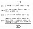
도 5a는 본 발명에 따른 이동 로봇을 작업영역의 특정 지점으로 복귀시키는 방법과 관련된 일 실시예를 나타낸 흐름도이다.
도 5b 내지 도 5d는 도 5a에 도시된 일 실시예를 나타내는 개념도이다.
도 6a는 본 발명에 따른 이동 로봇의 작업영역의 경사도에 대한 주행 제어 방법의 일 실시예를 나타낸 흐름도이다.
도 6b 및 도 6c는 도 6a에 도시된 일 실시예를 나타내는 개념도이다.
도 7a는 본 발명에 따른 이동 로봇의 작업영역 내에 장애물 존재 여부를 판단하는 방법의 일 실시예를 나타낸 흐름도이다.
도 7b는 도 7a에 도시된 일 실시예를 나타내는 개념도이다.1A and 1B are conceptual diagrams illustrating an embodiment in which a mobile robot and a charging apparatus for a mobile robot according to the present invention are installed in a work area of a mobile robot.
1C and 1D are conceptual diagrams showing an embodiment of a mobile robot.
1E is a block diagram for explaining a mobile robot related to the present invention.
2 is a flowchart illustrating a method of controlling a mobile robot according to an embodiment of the present invention.
3A is a flowchart showing an embodiment of a method for generating map information related to a work area of a mobile robot according to the present invention.
FIGS. 3B to 3E are conceptual diagrams showing the embodiment shown in FIG. 3A.
4A is a flowchart showing an embodiment of a method of dividing a working area of a mobile robot according to the present invention into a plurality of areas.
4B to 4G are conceptual diagrams showing an embodiment shown in FIG. 4A.
5A is a flowchart illustrating an embodiment of a method for returning a mobile robot according to the present invention to a specific point in a work area.
5B to 5D are conceptual diagrams showing an embodiment shown in FIG. 5A.
FIG. 6A is a flowchart illustrating an operation control method for a tilt of a work area of a mobile robot according to an embodiment of the present invention.
6B and 6C are conceptual diagrams showing an embodiment shown in FIG. 6A.
FIG. 7A is a flowchart illustrating a method for determining whether an obstacle exists in a work area of a mobile robot according to an exemplary embodiment of the present invention. Referring to FIG.
FIG. 7B is a conceptual diagram showing the embodiment shown in FIG. 7A.
이하, 첨부된 도면을 참조하여 본 명세서에 개시된 실시 예를 상세히 설명하되, 동일하거나 유사한 구성요소에는 동일·유사한 도면 부호를 부여하고 이에 대한 중복되는 설명은 생략하기로 한다. 이하의 설명에서 사용되는 구성요소에 대한 접미사 "유닛" 및 "부"는 명세서 작성의 용이함만이 고려되어 부여되거나 혼용되는 것으로서, 그 자체로 서로 구별되는 의미 또는 역할을 갖는 것은 아니다. 또한, 본 명세서에 개시된 실시 예를 설명함에 있어서 관련된 공지 기술에 대한 구체적인 설명이 본 명세서에 개시된 실시 예의 요지를 흐릴 수 있다고 판단되는 경우 그 상세한 설명을 생략한다. 또한, 첨부된 도면은 본 명세서에 개시된 실시 예를 쉽게 이해할 수 있도록 하기 위한 것일 뿐, 첨부된 도면에 의해 본 명세서에 개시된 기술적 사상이 제한되지 않으며, 본 발명의 사상 및 기술 범위에 포함되는 모든 변경, 균등물 내지 대체물을 포함하는 것으로 이해되어야 한다.Hereinafter, embodiments of the present invention will be described in detail with reference to the accompanying drawings, wherein like or similar elements are denoted by the same or similar reference numerals, and a duplicate description thereof will be omitted. Suffix "unit " and" part "for constituent elements used in the following description are given or mixed in consideration only of ease of specification, and do not have their own meaning or role. In the following description of the embodiments of the present invention, a detailed description of related arts will be omitted when it is determined that the gist of the embodiments disclosed herein may be blurred. It is to be understood that both the foregoing general description and the following detailed description are exemplary and explanatory and are intended to provide further explanation of the invention as claimed. , ≪ / RTI > equivalents, and alternatives.
제1, 제2 등과 같이 서수를 포함하는 용어는 다양한 구성요소들을 설명하는데 사용될 수 있지만, 상기 구성요소들은 상기 용어들에 의해 한정되지는 않는다. 상기 용어들은 하나의 구성요소를 다른 구성요소로부터 구별하는 목적으로만 사용된다.Terms including ordinals, such as first, second, etc., may be used to describe various elements, but the elements are not limited to these terms. The terms are used only for the purpose of distinguishing one component from another.
어떤 구성요소가 다른 구성요소에 "연결되어" 있다거나 "접속되어" 있다고 언급된 때에는, 그 다른 구성요소에 직접적으로 연결되어 있거나 또는 접속되어 있을 수도 있지만, 중간에 다른 구성요소가 존재할 수도 있다고 이해되어야 할 것이다. 반면에, 어떤 구성요소가 다른 구성요소에 "직접 연결되어" 있다거나 "직접 접속되어" 있다고 언급된 때에는, 중간에 다른 구성요소가 존재하지 않는 것으로 이해되어야 할 것이다.It is to be understood that when an element is referred to as being "connected" or "connected" to another element, it may be directly connected or connected to the other element, . On the other hand, when an element is referred to as being "directly connected" or "directly connected" to another element, it should be understood that there are no other elements in between.
단수의 표현은 문맥상 명백하게 다르게 뜻하지 않는 한, 복수의 표현을 포함한다.The singular expressions include plural expressions unless the context clearly dictates otherwise.
본 출원에서, "포함한다" 또는 "가지다" 등의 용어는 명세서상에 기재된 특징, 숫자, 단계, 동작, 구성요소, 부품 또는 이들을 조합한 것이 존재함을 지정하려는 것이지, 하나 또는 그 이상의 다른 특징들이나 숫자, 단계, 동작, 구성요소, 부품 또는 이들을 조합한 것들의 존재 또는 부가 가능성을 미리 배제하지 않는 것으로 이해되어야 한다.
In the present application, the terms "comprises", "having", and the like are used to specify that a feature, a number, a step, an operation, an element, a component, But do not preclude the presence or addition of one or more other features, integers, steps, operations, elements, components, or combinations thereof.
도 1a 및 1b는 본 발명에 따른 이동 로봇(10)의 충전 장치(100)가 이동 로봇의 작업 영역(1000)에 설치된 일 실시예를 나타낸 개념도이다.1A and 1B are conceptual diagrams showing an embodiment in which the
도 1a를 참조하면, 이동 로봇(10)은 소정의 영역 내에서 스스로 주행할 수 있다. 또한, 상기 이동 로봇(10)은 주행 중에 특정 작업을 수행할 수 있다.Referring to FIG. 1A, the
보다 구체적으로, 이동 로봇(10)은 잔디 깎기 로봇일 수 있다. 이 경우, 상기 특정 작업은, 작업 영역(1000) 내의 잔디를 절삭하는 것일 수 있다.More specifically, the
또한, 상기 작업 영역(1000)은 폐곡선 또는 페루프로 형성되는 와이어(1200)에 의해 정의될 수 있다. 구체적으로, 상기 와이어(1200)는 임의의 영역에 설치될 수 있으며, 상기 이동 로봇(10)은 설치된 와이어(1200)에 의해 형성되는 폐곡선에 의해 정의되는 영역 내에서 이동할 수 있다.Also, the
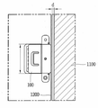
한편, 도 1b를 참조하면, 와이어(1200)는 작업 영역의 내부에 설치될 수 있다. 보다 구체적으로, 와이어(1200)는, 이동 로봇(10)의 작업 영역(1000)과 외부 영역(1100)의 경계선에 설치되거나, 외부 영역(1100)으로부터 소정의 간격(d)으로 설치될 수 있다. 이 경우, 와이어(1200)가 설치되는 상기 소정의 간격(d)의 값은 변동가능하다.Meanwhile, referring to FIG. 1B, the
따라서, 사용자는 작업 영역(1000)의 외곽을 따라 와이어(1200)를 설치할 수 있고, 상기 외곽 또는 상기 외부 영역(1100)으로부터 상기 와이어(1200)가 설치되는 간격을 고려할 필요가 없으므로, 와이어(1200)를 보다 쉽게 설치할 수 있다.Therefore, the user can install the
도 1b에 도시된 것과 같이, 이동 로봇(10)의 충전 장치(100)는 와이어(1200)와 연결되도록 설치될 수 있다. 한편, 도 1b에 도시되지는 않았으나, 상기 충전 장치(100)는 와이어(1200)가 설치된 영역을 포함하는 작업 영역(1000)의 일부 영역에 설치될 수도 있다. 또한, 도 1b에 도시되지는 않았으나, 상기 충전 장치(100)는 작업 영역(1000)의 일부 영역과, 외부 영역(1100)의 일부 영역에 설치될 수도 있다.1B, the charging
이하의 도 1c 및 1d에서는 상기 이동 로봇(10)이 잔디 깎기 로봇인 경우, 본 발명과 관련된 잔디 깎기 로봇의 일 실시예가 설명된다.1C and 1D below, when the
도 1c 및 1d를 참조하면, 잔디 깎기 로봇(10)은 이동이 가능하도록 마련되어서, 잔디를 절삭할 수 있는 본체(50)를 포함할 수 있다. 상기 본체(50)는, 와이어(1200) 내에서 이동하면서, 작업 영역(1000) 내의 잔디를 절삭할 수 있다.Referring to Figs. 1C and 1D, the
아울러, 와이어(1200)는, 와이어에 전류를 공급할 수 있는 충전 장치(100)에 연결될 수 있다. 즉 상기 와이어(1200)는 충전 장치(100)에 연결되어서 충전 장치(100)에서 공급되는 전류에 의해서 자기장을 발생시킬 수 있다. 또한 상기 충전 장치(100)에 결합되어 상기 본체(50)가 충전될 수 있다.In addition, the
잔디 깎기 로봇의 본체(50)에는 잔디를 절삭할 수 있는 절삭부(미도시)가 구비될 수 있다. 상기 절삭부에는 날카로운 칼날이 회전되도록 하는 구성이 배치될 수 있다.The
상기 본체(50)에는 상기 본체(50)를 원하는 방향으로 이동시키고, 회전시킬 수 있는 구동부가 마련된다. 상기 구동부는 복수 개의 회전가능한 바퀴를 포함할 수 있고, 각각의 바퀴는 개별적으로 회전될 수 있어서, 상기 본체(50)는 원하는 방향으로 회전될 수 있다. 보다 구체적으로 상기 구동부는 적어도 하나의 주 구동바퀴(40)와, 보조 바퀴(20)를 포함할 수 있다. 예를 들어, 상기 본체(50)는 두개의 주 구동 바퀴(40)를 포함할 수 있으며, 상기 주 구동 바퀴는 본체(50)의 후방 저면에 설치될 수 있다.The
상기 본체(50)에는 상기 와이어(1200)를 감지할 수 있는 감지부를 포함할 수 있다. 상기 감지부는 상기 와이어(1200)에 흐르는 전류에 의해서 발생되는 자기장과 그에 따라 유도되어 발생되는 전압값을 감지해서, 상기 본체(50)가 상기 와이어(1200)에 도달했는지, 상기 본체(50)가 상기 경계와이어(1200)에 의해서 형성되는 폐곡면 내에 존재하는지, 상기 본체(50)가 상기 와이어(1200)를 따라서 주행하고 있는지 등에 관한 정보를 획득할 수 있다.The
또한 상기 감지부는 상기 본체(50)의 이동 거리, 이동 속도, 이동에 따른 상대적인 위치 변화 등에 관한 다양한 정보를 감지하는 것도 가능하다.Further, the sensing unit may sense various information related to the movement distance, the movement speed, and the relative positional change with the movement of the
상기 본체(50)는 상기 감지부에서 감지된 정보를 이용해서, 상기 구동부(40)를 구동할 수 있다. 즉 상기 제어부(18)는 상기 감지부에서 측정한 정보를 이용해서 상기 본체(50)의 주행을 제어해서, 상기 본체(50)가 작업 영역 내부에 위치하도록 상기 구동부를 구동하는 것도 가능하다.The
상기 본체(50)는 상기 와이어(1200)로부터 유도되는 전압값을 감지하는 감지부와, 상기 감지부에서 감지된 전압값에 의해서 상기 본체(50)와 상기 와이어(1200)의 거리를 판단하는 제어부(18)를 포함할 수 있다.The
상기 본체(50)는 충전 장치(100)와 접촉하여 전력을 공급받도록, 전력 수신부(60)를 포함할 수 있다. 상기 전력 수신부(60)는 적어도 하나의 단자를 포함할 수 있다. 구체적으로, 상기 단자는 탄성부(미도시)와 결합되어, 상하 이동이 가능하도록 형성될 수 있다. 상기 전력 수신부(60)는 구동부의 주 구동바퀴(40) 중 어느 하나의 상방에 설치될 수 있다. 아울러, 상기 전력 수신부(60)는 본체(50)의 상방으로 노출되도록 설치될 수 있다.The
이하의 도 1e에서는 본 발명에 따른 이동 로봇의 일 실시예가 설명된다.1E, an embodiment of a mobile robot according to the present invention will be described.
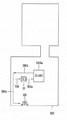
도 1e에 도시된 것과 같이, 이동 로봇(10)은 통신부(11), 입력부(12), 구동부(13), 센싱부(14), 출력부(15), 메모리(17), 제어부(18) 및 전원공급부(19) 중 적어도 하나를 포함할 수 있다. 도 1e에 도시된 구성요소들은 이동 로봇을 구현하는데 있어서 필수적인 것은 아니어서, 본 명세서 상에서 설명되는 이동 로봇은 위에서 열거된 구성요소들 보다 많거나, 또는 적은 구성요소들을 가질 수 있다. 1E, the
보다 구체적으로, 상기 구성요소들 중 무선 통신부(11)는, 이동 로봇(10)와 무선 통신 시스템 사이, 이동 로봇(10)과 다른 이동 로봇 사이, 이동 로봇(10)과 이동 단말기(미도시) 사이, 이동 로봇(10)과 충전 장치(100)의 통신유닛(미도시) 사이 또는 이동 로봇(10)과 외부서버 사이의 무선 통신을 가능하게 하는 하나 이상의 모듈을 포함할 수 있다. 또한, 상기 통신부(11)는, 이동 로봇(10)을 하나 이상의 네트워크에 연결하는 하나 이상의 모듈을 포함할 수 있다.More specifically, the wireless communication unit 11 among the above-described components can communicate with the
이러한 통신부(11)는, 이동통신 모듈, 무선 인터넷 모듈, 근거리 통신 모듈, 위치정보 모듈 중 적어도 하나를 포함할 수 있다.The communication unit 11 may include at least one of a mobile communication module, a wireless Internet module, a local area communication module, and a location information module.
입력부(12)는, 영상 신호 입력을 위한 카메라 또는 영상 입력부, 오디오 신호 입력을 위한 마이크로폰(microphone), 또는 오디오 입력부, 사용자로부터 정보를 입력받기 위한 사용자 입력부(예를 들어, 터치키(touch key), 푸시키(mechanical key) 등)를 포함할 수 있다. 입력부(12)에서 수집한 음성 데이터나 이미지 데이터는 분석되어 사용자의 제어명령으로 처리될 수 있다.The input unit 12 includes a camera or an image input unit for inputting a video signal, a microphone for inputting an audio signal, an audio input unit, a user input unit (e.g., a touch key) for receiving information from a user, , A mechanical key, etc.). The voice data or image data collected by the input unit 12 may be analyzed and processed by a user's control command.
센싱부(14)는 이동 단말기 내 정보, 이동 단말기를 둘러싼 주변 환경 정보 및 사용자 정보 중 적어도 하나를 센싱하기 위한 하나 이상의 센서를 포함할 수 있다. 예를 들어, 센싱부(14)는 근접센서(proximity sensor), 조도 센서(illumination sensor), 터치 센서(touch sensor), 가속도 센서(acceleration sensor), 자기 센서(magnetic sensor), 중력 센서(G-sensor), 자이로스코프 센서(gyroscope sensor), 모션 센서(motion sensor), RGB 센서, 적외선 센서(IR 센서: infrared sensor), 지문인식 센서(finger scan sensor), 초음파 센서(ultrasonic sensor), 광 센서(optical sensor, 예를 들어, 카메라), 마이크로폰(microphone), 배터리 게이지(battery gauge), 환경 센서(예를 들어, 기압계, 습도계, 온도계, 방사능 감지 센서, 열 감지 센서, 가스 감지 센서 등), 화학 센서(예를 들어, 전자 코, 헬스케어 센서, 생체 인식 센서 등) 중 적어도 하나를 포함할 수 있다.The sensing unit 14 may include at least one sensor for sensing at least one of information in the mobile terminal, surrounding environment information surrounding the mobile terminal, and user information. For example, the sensing unit 14 may include a proximity sensor, an illumination sensor, a touch sensor, an acceleration sensor, a magnetic sensor, a gravity sensor G- sensor, a gyroscope sensor, a motion sensor, an RGB sensor, an infrared sensor, a finger scan sensor, an ultrasonic sensor, an optical sensor optical sensors, such as cameras), microphones, battery gauges, environmental sensors (e.g., barometers, hygrometers, thermometers, radiation sensors, thermal sensors, A sensor (e. G., An electronic nose, a healthcare sensor, a biometric sensor, etc.).
센싱부(14)는 다르게 설치되는 적어도 두 개의 코일을 포함하며, 상기 두 개의 코일은, 상기 와이어(1200)를 기준으로 구분되는 동일한 영역 내에서 각각 전압값을 감지하는 것이 가능하다. 즉 상기 두 개의 코일은 상기 와이어(1200)에 의한 폐루프(closed loop)의 내부에서 전압값을 감지하는 것이 가능하다.The sensing unit 14 includes at least two coils that are installed differently, and the two coils are capable of sensing a voltage value within the same area divided by the
또한, 센싱부(14)는 휠 센서를 포함하며, 상기 휠 센서는 구동부(13)에 포함되는 주 구동바퀴 및 보조 구동바퀴 중 적어도 하나의 작동 이력과 관련된 정보를 감지할 수 있다.Also, the sensing unit 14 may include a wheel sensor, and the wheel sensor may sense information related to an operation history of at least one of the main driving wheels and the auxiliary driving wheels included in the driving unit 13.
한편, 본 명세서에 개시된 이동 로봇은, 이러한 센서들 중 적어도 둘 이상의 센서에서 센싱되는 정보들을 조합하여 활용할 수 있다.Meanwhile, the mobile robot disclosed in the present specification can combine and utilize information sensed by at least two of the sensors.
출력부(15)는 시각, 청각 또는 촉각 등과 관련된 출력을 발생시키기 위한 것으로, 디스플레이부, 음향 출력부, 진동 모듈, 광 출력부 중 적어도 하나를 포함할 수 있다. 디스플레이부는 터치 센서와 상호 레이어 구조를 이루거나 일체형으로 형성됨으로써, 터치 스크린을 구현할 수 있다. 이러한 터치 스크린은, 이동 로봇(10)과 사용자 사이의 입력 인터페이스를 제공하는 사용자 입력부로써 기능함과 동시에, 이동 로봇(10)과 사용자 사이의 출력 인터페이스를 제공할 수 있다.The output unit 15 is for generating output related to visual, auditory or tactile sense, and may include at least one of a display unit, a sound output unit, a vibration module, and a light output unit. The display unit may have a mutual layer structure with the touch sensor or may be integrally formed to realize a touch screen. The touch screen functions as a user input unit for providing an input interface between the
또한, 메모리(17)는 이동 로봇(10)의 다양한 기능을 지원하는 데이터를 저장한다. 메모리(17)는 이동 로봇(10)에서 구동되는 다수의 응용 프로그램(application program 또는 애플리케이션(application)), 이동 로봇(10)의 동작을 위한 데이터들, 명령어들을 저장할 수 있다. 이러한 응용 프로그램 중 적어도 일부는, 무선 통신을 통해 외부 서버로부터 다운로드 될 수 있다. 또한 이러한 응용 프로그램 중 적어도 일부는, 이동 로봇(10)의 기본적인 기능(예를 들어, 절삭 기능, 이동 기능, 충방전 기능, 통신 기능)을 위하여 출고 당시부터 이동 로봇(10)상에 존재할 수 있다. 한편, 응용 프로그램은, 메모리(17)에 저장되고, 이동 로봇(10) 상에 설치되어, 제어부(18)에 의하여 상기 이동 로봇의 동작(또는 기능)을 수행하도록 구동될 수 있다.In addition, the memory 17 stores data supporting various functions of the
제어부(18)는 상기 응용 프로그램과 관련된 동작 외에도, 통상적으로 이동 로봇(10)의 전반적인 동작을 제어한다. 제어부(18)는 위에서 살펴본 구성요소들을 통해 입력 또는 출력되는 신호, 데이터, 정보 등을 처리하거나 메모리(17)에 저장된 응용 프로그램을 구동함으로써, 사용자에게 적절한 정보 또는 기능을 제공 또는 처리할 수 있다.The control unit 18 generally controls the overall operation of the
또한, 제어부(18)는 메모리(17)에 저장된 응용 프로그램을 구동하기 위하여, 도 1e와 함께 살펴본 구성요소들 중 적어도 일부를 제어할 수 있다. 나아가, 제어부(18)는 상기 응용 프로그램의 구동을 위하여, 이동 로봇(10)에 포함된 구성요소들 중 적어도 둘 이상을 서로 조합하여 동작시킬 수 있다.In addition, the control unit 18 may control at least some of the components illustrated in FIG. 1E in order to drive an application program stored in the memory 17. FIG. Furthermore, the control unit 18 may operate at least two of the components included in the
전원공급부(19)는 제어부(18)의 제어 하에서, 외부의 전원, 내부의 전원을 인가 받아 이동 로봇(10)에 포함된 각 구성요소들에 전원을 공급한다. 이러한 전원공급부(19)는 배터리를 포함하며, 상기 배터리는 내장형 배터리 또는 교체가능한 형태의 배터리가 될 수 있다.Under the control of the control unit 18, the power supply unit 19 receives external power and internal power, and supplies power to the respective components included in the
상기 각 구성요소들 중 적어도 일부는, 이하에서 설명되는 다양한 실시 예들에 따른 이동 단말기의 동작, 제어, 또는 제어방법을 구현하기 위하여 서로 협력하여 동작할 수 있다. 또한, 상기 이동 단말기의 동작, 제어, 또는 제어방법은 상기 메모리(17)에 저장된 적어도 하나의 응용 프로그램의 구동에 의하여 이동 단말기 상에서 구현될 수 있다. At least some of the components may operate in cooperation with one another to implement a method of operation, control, or control of a mobile terminal according to various embodiments described below. In addition, the operation, control, or control method of the mobile terminal can be implemented on the mobile terminal by driving at least one application program stored in the memory 17. [
이하의 도 2에서는 본 발명에 따른 이동 로봇의 제어방법의 일 실시예가 설명된다.2, an embodiment of a method of controlling a mobile robot according to the present invention will be described.
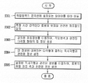
도 2에 도시된 것과 같이, 이동 로봇(10)은 작업영역에 대응하는 맵 정보를 생성할 수 있다(S201).As shown in Fig. 2, the
구체적으로, 이동 로봇(10)이 작업영역의 윤곽선에 설치된 와이어(1200)를 따라 이동하는 동안, 이동 로봇(10)의 이동 경로와 관련된 복수의 좌표정보를 감지할 수 있다. 아울러, 이동 로봇(10)은 상기 감지된 복수의 좌표정보를 이용하여 작업영역에 대응하는 맵 정보를 생성할 수 있다.Specifically, while the
또한, 이동 로봇(10)는 작업영역이 복수의 영역으로 분할되도록, 맵 정보를 이용하여 상기 복수의 영역과 관련된 정보를 설정할 수 있다(S202).In addition, the
구체적으로, 이동 로봇(10)의 제어부(18)는 작업영역의 형태와 관련된 정보에 근거하여, 작업영역을 복수의 영역으로 분할할 수 있다. 또한, 제어부(18)는 이동 로봇(10)의 성능과 관련된 정보에 근거하여, 작업영역을 복수의 영역으로 분할할 수 있다. Specifically, the control unit 18 of the
이동 로봇(10)는 상기 분할된 복수의 영역 별로 기 설정된 이동 패턴에 따라 이동할 수 있다(S203).The
아울러, 이동 로봇(10)는 분할된 영역 별로, 기 설정된 이동 패턴에 따라 이동하면서, 잔디 절삭 기능을 수행할 수 있다. 구체적으로, 이동 로봇(10)은 분할된 영역 별로, 소정의 횟수만큼 반복하여 지그재그 운전을 수행하면서, 잔디 절삭 기능을 수행할 수 있다.In addition, the
이동 로봇(10)의 작업영역에 대한 작업 수행이 완료되면, 이동 로봇(10)은 충전장치(100)로 복귀할 수 있다(S204).When the operation of the work area of the
한편, 이동 로봇(10)은 작업영역에 대한 작업 수행이 완료되기 전에도, 이동 로봇(10)에서 복귀 이벤트가 발생되면, 충전장치(100)로 복귀할 수 있다.The
이하의 명세서에서는, 이동 로봇(10)의 일 예로서, 잔디 깎기 로봇과 관련된 다양한 실시예가 설명된다. 즉, 이동 로봇(10), 로봇(10) 및 잔디 깎기 로봇(10)은 서로 대응되는 개념으로서, 로봇(10) 및 잔디 깎기 로봇(10)은 상기 도 1a 내지 도 1e에 도시된 이동 로봇(10)의 구성을 포함할 수 있다. 다만, 본 발명의 구성은 잔디 깎기 로봇에 한정되는 것은 아니며, 다양한 이동 로봇에 적용될 수 있다.In the following specification, various examples related to the lawn mower robot are described as an example of the
이하의 도 3a 내지 도 3e는 본 발명에 따른 잔디 깎기 로봇의 작업영역과 관련된 맵 정보를 생성하는 방법의 일 실시예가 설명된다.3A to 3E, an embodiment of a method of generating map information related to a work area of a lawn mower robot according to the present invention will be described.
도 3a에 도시된 것과 같이, 잔디 깎기 로봇(10)의 구동부(13)는 소정 작업영역(1000)의 윤곽선에 설치되는 와이어(1200)를 따라 이동할 수 있다(S301).3A, the driving unit 13 of the
구체적으로, 잔디 깎기 로봇(10)의 구동부(13)는 잔디 깎기 로봇의 본체가 상기 와이어(1200)를 따라 이동하도록 구동할 수 있다. 구동부(13)는 로봇의 상기 본체의 무게중심이 와이어(1200)로부터 소정의 거리만큼 이격되도록 구동할 수 있다.More specifically, the driving unit 13 of the
예를 들어, 구동부(13)는 상기 로봇의 주 구동바퀴 중 어느 하나가 상기 와이어(1200)에 접한 상태에서 상기 로봇을 이동시키도록 구동할 수 있다. 또 다른 예에서, 구동부(13)는 상기 와이어(1200)가 형성하는 폐루프에 대응하는 이동경로로 상기 로봇을 이동시키도록 구동할 수 있다.For example, the driving unit 13 may drive the robot to move in a state where any one of the main driving wheels of the robot is in contact with the
한편, 센싱부(14)는 와이어로부터 유도되는 전압값을 감지할 수 있고, 제어부(18)는 상기 감지된 전압값을 이용하여, 로봇(10)의 본체와 와이어(1200)와의 거리를 판단할 수 있다. 이로써, 제어부(18)는 본체와 와이어 사이의 거리에 대한 판단결과에 근거하여, 구동부를 제어할 수 있다.Meanwhile, the sensing unit 14 may sense a voltage value derived from the wire, and the controller 18 may determine the distance between the body of the
다음으로, 센싱부(14)는 특정 시간 간격마다 로봇의 위치와 관련된 좌표정보를 감지할 수 있다.Next, the sensing unit 14 may sense coordinate information related to the position of the robot at specific time intervals.
구체적으로, 센싱부(14)는 사용자에 의해 설정된 시간 간격마다 로봇의 현재 위치와 관련된 좌표정보를 감지할 수 있다.Specifically, the sensing unit 14 may sense coordinate information related to the current position of the robot at a time interval set by the user.
예를 들어, 센싱부(14)는 구동부(13)에 포함된 구동바퀴의 작동 상태 및 작동 이력 중 적어도 하나와 관련된 정보를 감지하는 휠 센서 또는 자이로 센서를 포함할 수 있다. 이 경우, 상기 구동바퀴의 작동 상태와 관련된 정보는, 현재의 이동 방향 및 이동 속도와 관련된 정보를 포함할 수 있다.For example, the sensing unit 14 may include a wheel sensor or a gyro sensor that senses information related to at least one of an operating state and an operation history of the driving wheels included in the driving unit 13. [ In this case, the information related to the operating state of the driving wheels may include information related to the current moving direction and the moving speed.
또한, 휠 센서는 구동바퀴의 작동 이력과 관련된 정보를 감지할 수 있고, 제어부(18)는 기 설정된 기준 좌표정보를 이용하여, 상기 구동바퀴의 작동 이력과 관련되어 감지된 정보를 로봇의 현재위치와 관련된 좌표정보로 변환할 수 있다.In addition, the wheel sensor can sense information related to the operating history of the driving wheels, and the controller 18 can use the predetermined reference coordinate information to detect information related to the operating history of the driving wheels, Can be converted into coordinate information related to the coordinate system.
또 다른 예에서, 센싱부(14)는 로봇(10)의 GPS 좌표정보를 감지하는 GPS모듈을 포함할 수 있다. 이 경우, 사용자에 의해 별도로 기준 좌표정보가 설정되지 않아도, 센싱부(14)는 GPS모듈을 통하여, 로봇의 현재위치와 관련된 좌표정보를 감지할 수 있다.In another example, the sensing unit 14 may include a GPS module that senses the GPS coordinate information of the
이와 관련하여, 도 3b를 참조하면, 로봇(10)이 와이어(1200)를 이동함에 따라, 센싱부(14)는 복수의 좌표정보(310)를 감지할 수 있다.In this regard, referring to FIG. 3B, as the
일 실시예에서, 좌표정보(310) 상호 간의 간격은 센싱부(14)의 속성에 따라 변경될 수 있다. 또 다른 실시예에서, 제어부(18)는 좌표정보의 감지 주기와 관련된 사용자 입력에 근거하여, 센싱부(14)가 특정 주기로 좌표정보를 감지하도록 상기 센싱부(14)를 제어할 수도 있다.In one embodiment, the interval between the coordinate
한편, 제어부(18)는 센싱부(14)에서 감지된 로봇의 현재 위치와 관련된 좌표정보를 변환하여 와이어가 설치된 지점에 대응하는 좌표정보를 생성할 수 있다. 구체적으로, 센싱부(14)는 본체의 무게중심에 대응하는 제1 좌표정보와, 상기 제1 좌표정보가 감지된 시점의 본체의 자세와 관련된 정보를 감지할 수 있다. 이 경우, 제어부(18)는 상기 본체의 자세와 관련된 정보를 이용하여, 상기 제1 좌표정보를 와이어가 설치된 지점에 대응하는 제2 좌표정보로 변환할 수 있다. 이로써, 본 발명에 따른 잔디 깎기 로봇(10)은, 와이어가 설치된 복수의 지점과 대응되는 복수의 좌표정보를 획득할 수 있다.The control unit 18 may convert coordinate information related to the current position of the robot detected by the sensing unit 14 to generate coordinate information corresponding to a point where the wire is installed. Specifically, the sensing unit 14 may sense first coordinate information corresponding to the center of gravity of the main body and information related to the main body posture at the time when the first coordinate information is sensed. In this case, the controller 18 may convert the first coordinate information into second coordinate information corresponding to a point where the wire is installed, using information related to the posture of the main body. Thus, the
다음으로, 제어부(18)는 센싱부(14)에서 감지된 좌표정보를 이용하여, 작업영역(1000)과 관련된 다각형 형태의 맵 정보를 생성할 수 있다(S303).Next, the control unit 18 can generate map information of a polygonal shape related to the
보다 구체적으로, 제어부(18)는 감지된 복수의 좌표정보(310)에 대해 필터링을 수행하여, 상기 복수의 좌표정보(310) 중 적어도 일부를 선택할 수 있다.More specifically, the control unit 18 may perform filtering on the detected plurality of coordinate
이와 관련하여, 도 3c를 참조하면, 제어부(18)는 센싱부(14)로부터 감지된 복수의 좌표정보(310) 중 일부의 좌표정보(320)를 선택할 수 있다.3C, the controller 18 can select a part of the coordinate
구체적으로, 제어부(18)는 감지된 복수의 좌표정보(310)가 센싱부(14)에서 감지된 순서에 근거하여, 복수의 좌표정보(310)를 순차적으로 연결하는 선분과 관련된 정보를 설정할 수 있다. 이로써, 제어부(18)는 상기 선분과 관련된 정보를 이용하여, 복수의 좌표정보(310)를 복수의 그룹으로 그룹화할 수 있다.Specifically, the control unit 18 can set information related to a line segment that successively connects the plurality of coordinate
예를 들어, 제어부(18)는 실질적으로 직선을 형성하는 복수의 좌표정보(310) 중 일부를 동일한 그룹으로 그룹화할 수 있다. 이로써, 제어부(18)는 그룹화된 좌표정보 중 양 끝단에 위치한 좌표정보를 선택할 수 있다.For example, the control unit 18 may group some of a plurality of coordinate
또 다른 예에서, 제어부(18)는 복수의 좌표정보(310) 중 서로 인접한 두개의 좌표정보가 형성하는 복수의 선분과 관련된 정보를 검출할 수 있다. 또한, 제어부(18)는 상기 검출된 복수의 선분이 형성하는 각도와 관련된 정보를 이용하여, 상기 복수의 좌표정보(310)에 대해 필터링을 수행할 수 있다. 제어부(18)는 상기 수행된 필터링 결과에 근거하여, 복수의 좌표정보(310) 중 적어도 일부를 선택할 수 있다.In another example, the control unit 18 can detect information related to a plurality of line segments formed by two coordinate information adjacent to each other among a plurality of coordinate
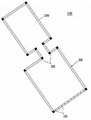
아울러, 제어부(18)는 선택된 좌표정보(320)를 이용하여, 다각형 형태의 맵 정보(330)를 생성할 수 있다. 즉, 제어부(18)는 복수의 좌표정보(310) 중 일부를 꼭지점으로 포함하는 다각형 형태의 맵 정보(330)를 생성할 수 있다.In addition, the control unit 18 can generate the
한편, 제어부(18)는 로봇(10)의 본체가 폐루프를 형성하는 와이어(1200)를 따라 이동한 이후, 좌표정보(310)를 감지하기 시작한 기준 지점으로 복귀하면, 상기 작업영역과 관련된 맵 정보의 생성이 완료된 것으로 판단할 수 있다. 이 경우, 상기 기준 지점은 로봇(10)의 충전장치(100)가 설치된 지점에 대응될 수 있다.On the other hand, when the main body of the
일 실시예에서, 제어부(18)는, 로봇(10)이 기 설정된 횟수만큼 상기 폐루프를 따라 순환 이동하는 경우, 상기 맵 정보의 생성이 완료된 것으로 판단할 수 있다. 이로써, 생성된 맵 정보의 정확도가 향상될 수 있다.In one embodiment, when the
다음으로, 제어부(18)는 생성된 맵 정보에 대응하는 다각형에 접하는 직사각형과 관련된 정보를 설정할 수 있다(S304). 또한, 제어부(18)는 설정된 직사각형과 관련된 정보를 이용하여, 로봇(10)의 주행 좌표축과 관련된 정보를 설정할 수 있다(S305).Next, the control unit 18 can set information related to the rectangle tangent to the polygon corresponding to the generated map information (S304). Further, the control unit 18 can set information related to the traveling coordinate axes of the
보다 구체적으로, 도 3d를 참조하면, 제어부(18)는 생성된 맵 정보에 대응되는 좌표축(331, 332)과 관련된 정보를 설정할 수 있다. 아울러, 제어부(18)는 작업영역에 대응하는 기준지점과 관련된 좌표정보(333)를 설정할 수 있다.More specifically, referring to FIG. 3D, the control unit 18 can set information related to the coordinate
예를 들어, 맵 정보에 대응되는 좌표축 정보는 전역 좌표축 정보일 수 있다. 즉, 맵 정보에 대응되는 좌표축 정보는, 남-북 방향에 대응하는 좌표축과, 동-서 방향에 대응하는 좌표축과 관련될 수 있다.For example, the coordinate axis information corresponding to the map information may be global coordinate axis information. That is, the coordinate axis information corresponding to the map information can be related to the coordinate axis corresponding to the south-north direction and the coordinate axis corresponding to the east-west direction.
아울러, 도 3d에 도시된 것과 같이, 제어부(18)는 생성된 맵 정보에 대응되는 다각형에 접하는 직사각형과 관련된 정보(340a)를 설정할 수 있다.3D, the control unit 18 can set the
보다 구체적으로, 제어부(18)는 상기 맵 정보에 대응되는 다각형과 적어도 4개의 접점에서 외접하는 직사각형과 관련된 정보(340a)를 설정할 수 있다. 제어부(18)는 외접하는 직사각형과 관련된 정보(340a)를 이용하여, 로봇(10)의 주행 좌표축(341a, 342a)과 관련된 정보를 설정할 수 있다.More specifically, the control unit 18 can set information (340a) related to a polygon corresponding to the map information and a rectangle circumscribing at at least four contact points. The control unit 18 can set information related to the traveling coordinate
이 경우, 제어부(18)는 상기 설정된 주행 좌표축(341a, 342a)과 관련된 정보를 이용하여, 로봇(10)의 주행 방향을 결정할 수 있다.In this case, the control unit 18 can determine the running direction of the
또한, 도 3e를 참조하면, 제어부(18)는 상기 맵 정보에 대응되는 다각형과, 상기 외접하는 직사각형의 면적 차이를 산출할 수 있다. 제어부(18)는 상기 산출된 면적 차이가 최소 값이 되도록 직사각형과 관련된 정보를 설정할 수 있다.Referring to FIG. 3E, the controller 18 can calculate the area difference between the polygon corresponding to the map information and the rectangle circumscribing the map information. The controller 18 can set information related to the rectangle so that the calculated area difference becomes a minimum value.
보다 구체적으로, 제어부(18)는 상기 설정된 주행 좌표축(341a, 342a)을 회전시키면서, 상기 회전된 주행 좌표축에 대응되고, 상기 맵 정보(330)에 대응되는 다각형과 외접하는 직사각형(340b)과 관련된 정보를 재설정할 수 있다.More specifically, the control unit 18 rotates the set travel coordinate
이로써, 제어부(18)는 상기 다각형과 상기 직사각형의 면적 차이를 최소화시키는 상기 맵 정보와 관련된 좌표축(331, 332)과 상기 주행 좌표축(341b, 342b)의 각도 차이(θ)를 검출할 수 있다.The control unit 18 can detect an angle difference θ between the coordinate
일 실시예에서, 제어부(18)는 상기 주행 좌표축(341b, 342b)을 1°씩 회전시키면서, 상기 다각형과 상기 직사각형의 면적 차이를 최소화시키는 각도 차이(θ)를 검출할 수 있다.In one embodiment, the control unit 18 can detect the angle difference? That minimizes the area difference between the polygon and the rectangle while rotating the traveling coordinate axes 341b and 342b by 1 占.
위와 같이, 제어부(18)는 상기 다각형에 외접하는 직사각형과, 상기 직사각형에 대응되는 주행 좌표축(341a, 342a)와 관련된 정보를 설정할 수 있고, 메모리(17)는 상기 설정된 정보와 함께, 상기 직사각형의 제1 및 제2 변의 길이와 관련된 정보를 저장할 수 있다.As described above, the control unit 18 can set information related to the rectangle circumscribing the polygon and the coordinate
이 경우, 제어부(18)는 로봇(10)이 제1 주행 좌표축(341a) 방향으로 진행하면서, 제2 주행 좌표축(342a) 방향으로 왕복 운전하도록 구동부(13)를 제어할 수 있다. 또한, 제어부(18)는 로봇(10)이 제2 주행 좌표축(342a) 방향으로 왕복 운전을 수행하는, 지그재그 주행에 의해 이동하도록, 상기 구동부(13)를 제어할 수 있다.In this case, the control unit 18 can control the driving unit 13 so that the
이하의 도 4a 및 도 4b 내지 4g에서는, 본 발명에 따른 잔디 깎기 로봇이, 작업영역을 복수의 영역으로 분할하여, 복수의 영역 별로 작업을 수행하는 방법을 나타낸 일 실시예가 설명된다.4A and 4B to 4G, an embodiment will be described in which a lawn mower robot according to the present invention divides a work area into a plurality of areas and performs work for a plurality of areas.
이하의 실시예에서 설명되는 잔디 깎기 로봇의 제어방법에서는, 도 3a에서 설명된 제어방법에 의해 설정된 주행 좌표축(400a, 400b)과 관련된 정보를 이용할 수도 있고, 사용자 입력을 수신하여 사용자에 의해 직접 설정된 주행 좌표축(400a, 400b)과 관련된 정보를 이용할 수도 있다. 또한, 이하의 실시예에서 설명되는 잔디 깎기 로봇의 제어방법에서는, 충전장치가 설치된 위치에 대응하는 기준 좌표정보를 이용할 수 있다.In the control method of the lawn mower robot described in the following embodiments, information related to the traveling coordinate
먼저, 제어부(18)는 작업영역을 형성하는 다각형의 꼭지점에 대응되는 좌표정보를 이용하여, 적어도 하나의 기준선과 관련된 제1 정보를 설정할 수 있다(S401).First, the control unit 18 can set first information related to at least one reference line by using coordinate information corresponding to a vertex of the polygon forming the work area (S401).
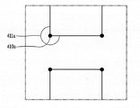
구체적으로, 도 4b를 참조하면, 제어부(18)는 작업영역을 형성하는 다각형과 관련된 맵 정보(330)를 이용하여, 상기 다각형의 꼭지점(320) 중 오목 꼭지점(410a, 410b, 410c, 410d)에 대응하는 좌표정보를 검출할 수 있다. 제어부(18)는 상기 검출된 오목 꼭지점에 대응하는 좌표정보를 이용하여, 상기 제1 정보를 설정할 수 있다.4B, the control unit 18 determines the
즉, 제어부(18)는 상기 오목 꼭지점에 대응하는 좌표정보를 이용하여, 적어도 하나의 기준선(420)과 관련된 제1 정보를 설정할 수 있다. 예를 들어, 상기 제1 정보는, 기준선(420)과 주행 좌표축이 형성하는 각도와 관련된 정보, 기준선(420)이 포함하는 오목 꼭지점(410a)의 좌표정보 등을 포함할 수 있다. 또 다른 예에서, 상기 기준선(420)은 오목 꼭지점을 포함하고, 미리 설정된 주행 좌표축 중 어느 하나에 평행할 수 있다.That is, the controller 18 can set the first information related to the at least one
예를 들어, 도 4c를 참조하면, 상기 오목 꼭지점(410a)을 중심으로 형성되는 다각형의 내각(411a)은 둔각일 수 있다. 즉, 제어부(18)는 다각형의 복수의 꼭지점 중 다각형의 내각이 둔각인 꼭지점을 오목 꼭지점(410a)으로 선택하기 위해, 상기 오목 꼭지점(410a)과 관련된 제1 정보를 설정할 수 있다.For example, referring to FIG. 4C, the
다음으로, 제어부(18)는 제1 정보를 이용하여, 작업영역이 복수의 영역으로 분할되도록, 복수의 영역과 관련된 제2 정보를 설정할 수 있다(S402).Next, using the first information, the control unit 18 can set the second information related to the plurality of areas so that the working area is divided into a plurality of areas (S402).
제어부(18)는 작업영역을 복수의 영역으로 분할시키는 적어도 하나의 기준선과 관련된 제1 정보를 설정할 수 있다. 또한, 제어부(18)는 상기 적어도 하나의 기준선을 이용하여, 작업영역이 복수의 영역으로 분할되도록, 복수의 영역과 관련된 제2 정보를 설정할 수 있다.The control unit 18 can set first information related to at least one reference line that divides the work area into a plurality of areas. Further, the control unit 18 can set the second information related to the plurality of areas such that the working area is divided into a plurality of areas using the at least one reference line.
예를 들어, 상기 제2 정보는 분할된 영역의 경계에 위치한 꼭지점에 대응하는 좌표정보, 분할된 각 영역의 식별정보, 분할된 각 영역의 면적과 관련된 정보 등을 포함할 수 있다.For example, the second information may include coordinate information corresponding to a vertex located at a boundary of the divided region, identification information of each divided region, information related to the area of each divided region, and the like.
제어부(18)는 선택된 오목 꼭지점에 대응하는 좌표정보를 이용하여, 작업영역을 복수의 영역으로 분할시키는 적어도 하나의 기준선과 관련된 정보를 설정할 수 있다.The control unit 18 can set information related to at least one reference line for dividing the work area into a plurality of areas by using the coordinate information corresponding to the selected concave vertex.
보다 구체적으로, 제어부(18)는 적어도 하나의 오목 꼭지점(410a, 410b, 410c, 410d)에 대응하는 좌표정보와 작업영역을 형성하는 다각형에 접하는 직사각형(도 3e 참조)과 관련된 좌표정보를 비교하여, 상기 적어도 하나의 오목 꼭지점 중 어느 하나를 선택할 수 있다.More specifically, the control unit 18 compares the coordinate information corresponding to at least one
즉, 제어부(18)는 작업영역을 형성하는 다각형에 포함된 상기 적어도 하나의 오목 꼭지점과 상기 직사각형의 일변 사이의 거리에 근거하여, 상기 적어도 하나의 오목 꼭지점 중 어느 하나를 선택할 수 있다. 예를 들어, 제어부(18)는 상기 적어도 하나의 오목 꼭지점 중 상기 직사각형의 일변으로부터 가장 멀리 떨어진 오목 꼭지점을 선택할 수 있다. 또 다른 예에서, 상기 직사각형의 일변은, 로봇의 주행 좌표축 중 어느 하나와 평행한 것일 수 있다.That is, the control unit 18 can select any one of the at least one concave vertexes based on the distance between the at least one concave vertex included in the polygon forming the work area and one side of the rectangle. For example, the control unit 18 may select a concave vertex farthest from the one side of the rectangle among the at least one concave vertex. In another example, the one side of the rectangle may be parallel to any one of the traveling coordinate axes of the robot.
이 경우, 제어부(18)는 상기 선택된 오목 꼭지점을 포함하고, 상기 주행 좌표축(400b)에 수직한 기준선과 관련된 정보를 설정할 수 있다. 아울러, 제어부(18)는 상기 주행 좌표축에 수직한 기준선을 이용하여, 작업영역을 복수의 영역으로 분할할 수 있다.In this case, the control unit 18 may include the selected concave vertex and set information related to the reference line perpendicular to the traveling coordinate
한편, 제어부(18)는 상기 적어도 하나의 오목 꼭지점으로부터 상기 직사각형의 제1 변까지의 거리 값과, 상기 직사각형의 제1 변과 수직한 제2 변의 길이 값을 비교하여, 상기 작업영역의 분할여부를 결정할 수 있다.On the other hand, the control unit 18 compares the distance value from the at least one concave vertex to the first side of the rectangle and the length value of the second side perpendicular to the first side of the rectangle, Can be determined.
즉, 적어도 하나의 오목 꼭지점 중 어느 하나로부터 상기 직사각형의 제1 변까지의 거리 값이, 상기 직사각형의 제1 변과 수직한 제2 변의 길이 값의 10% 이상인 경우, 제어부(18)는 상기 어느 하나의 오목 꼭지점을 기준으로 작업영역을 분할하도록 상기 제2 정보를 설정할 수 있다.That is, when the distance from one of the at least one concave vertex to the first side of the rectangle is 10% or more of the length of the second side perpendicular to the first side of the rectangle, The second information can be set to divide the work area on the basis of one concave vertex.
또한, 적어도 하나의 오목 꼭지점 중 어느 하나로부터 상기 직사각형의 제1 변까지의 거리 값이, 상기 직사각형의 제1 변과 수직한 제2 변의 길이 값의 미리 설정된 백분율 값 이하인 경우, 제어부(18)는 상기 어느 하나의 오목 꼭지점을 기준으로 작업영역을 분할하지 않을 수 있다. 예를 들어, 상기 미리 설정된 백분율 값은 10%일 수 있다.Further, when the distance value from any one of the at least one concave vertex to the first side of the rectangle is equal to or less than a preset percentage value of the length value of the second side perpendicular to the first side of the rectangle, The work area may not be divided based on any one of the concave vertexes. For example, the predetermined percentage value may be 10%.
제어부(18)는 기 설정된 주행방향과 관련된 제3 정보를 이용하여, 적어도 하나의 기준선 중 어느 하나를 선택할 수 있다. 아울러, 제어부(18)는 상기 선택된 기준선과 관련된 제1 정보를 이용하여, 작업영역에 포함된 복수의 영역과 관련된 제2 정보를 설정할 수 있다.The control unit 18 can select any one of the at least one reference line using the third information related to the predetermined traveling direction. In addition, the control unit 18 may set second information related to a plurality of areas included in the work area using the first information related to the selected reference line.
이 경우, 상기 제3 정보는, 도 3e에서 설명된 작업영역을 형성하는 다각형에 접하는 직사각형과 관련된 좌표축 정보(341a, 342a)를 포함할 수 있다. 즉, 제어부(18)는 작업영역을 형성하는 다각형과 최소의 면적 차이를 갖는 직사각형을 검출한 후, 상기 직사각형의 가로변 방향 또는 세로변 방향을 로봇의 주행방향으로 설정할 수 있다.In this case, the third information may include coordinate
아울러, 제어부(18)는 적어도 하나의 기준선 중 기 설정된 주행방향과 직교하는 어느 하나를 선택할 수 있다. 이로써, 제어부(18)는 작업영역에 포함된 복수의 영역과 관련된 제2 정보를 설정할 수 있다.In addition, the control unit 18 can select any one of the at least one reference line that is orthogonal to the predetermined running direction. Thereby, the control unit 18 can set the second information related to the plurality of areas included in the work area.
즉, 제어부(18)는 상기 어느 하나의 오목 꼭지점을 포함하고, 미리 설정된 주행 좌표축과 직교하는 기준선을 이용하여, 상기 작업영역을 복수의 영역으로 분할하도록, 상기 복수의 영역과 관련된 제2 정보를 설정할 수 있다.In other words, the control unit 18 uses the reference line orthogonal to the predetermined coordinate axis including any one of the concave vertexes to divide the working area into a plurality of areas, and the second information related to the plurality of areas Can be set.
한편, 제어부(18)는 복수의 오목 꼭지점이 검출된 경우, 상기 복수의 오목 꼭지점을 적어도 하나의 그룹으로 그룹화하고, 상기 그룹 별로 오목 꼭지점과 상기 직사각형의 일변까지의 거리가 최대인 오목 꼭지점을 선택할 수 있다. 또한, 제어부(18)는 그룹별로 선택된 오목 꼭지점을 포함하는 기준선을 이용하여, 상기 작업영역을 복수의 영역으로 분할하도록, 복수의 영역과 관련된 제2 정보를 설정할 수 있다.If a plurality of concave vertexes are detected, the control unit 18 groups the plurality of concave vertexes into at least one group, selects a concave vertex having a maximum distance from the concave vertex to the one side of the rectangle . Further, the control unit 18 can set the second information related to the plurality of areas so as to divide the working area into a plurality of areas, using the reference line including the concave vertexes selected for each group.
한편, 제어부(18)는 작업영역을 형성하는 다각형의 꼭지점 중 오목 꼭지점이 없는 것으로 판단되면, 소정의 최대 주행거리 값과 관련된 제4 정보를 이용하여, 상기 작업영역이 복수의 영역으로 분할되도록, 상기 제2 정보를 설정할 수 있다. 제어부(18)는 작업영역의 기 설정된 주행방향으로의 최대 너비 값이 상기 최대 주행거리 값보다 큰 경우, 상기 기 설정된 주행방향과 직교하는 기준선과 관련된 정보를 설정하여, 상기 작업영역을 복수의 영역으로 분할할 수 있다.On the other hand, when it is determined that there is no concave vertex among the vertexes of the polygon forming the work area, the control unit 18 uses the fourth information related to the predetermined maximum travel distance value to divide the work area into a plurality of areas, The second information can be set. The control unit 18 sets information related to the reference line orthogonal to the predetermined driving direction when the maximum width value in the predetermined driving direction of the working area is larger than the maximum driving distance value, .
예를 들어 상기 최대 주행거리 값은 20m으로 설정될 수 있다. 또 다른 예에서, 제어부(18)는 사용자 입력에 근거하여, 상기 최대 주행거리 값과 관련된 정보를 설정할 수 있다.For example, the maximum mileage value may be set to 20 m. In another example, the control unit 18 may set information related to the maximum mileage value based on user input.
일 실시예로서, 도 4d를 참조하면, 제어부(18)는 선택된 오목 꼭지점(410a, 410b, 410c, 410d)와 관련된 좌표정보를 이용하여, 상기 오목 꼭지점 중 일부를 포함하는 적어도 하나의 기준선(440a, 440b, 440c, 440d, 440e, 440f)과 관련된 제1 정보를 설정할 수 있다.4D, the control unit 18 may use at least one
또한, 도 4e를 참조하면, 제어부(18)는 기준선(441)과 관련된 제1 정보를 이용하여, 작업영역이 복수의 영역으로 분할되도록, 상기 복수의 영역(S1, S2)과 관련된 제2 정보를 설정할 수 있다.4E, the control unit 18 uses the first information related to the
다음으로, 제어부(18)는 제2 정보를 이용하여, 복수의 영역별로, 기 설정된 이동 패턴에 따라 본체가 이동하도록 구동부를 제어할 수 있다(S403).Next, using the second information, the control unit 18 can control the driving unit to move the main body according to a predetermined movement pattern for each of a plurality of areas (S403).
구체적으로, 도 4b에 도시된 것과 같이, 제어부(18)는 설정된 제2 정보를 이용하여, 분할된 복수의 영역 별로, 기 설정된 이동 패턴에 따라 로봇(10)의 본체가 이동하도록 구동부를 제어할 수 있다. 제어부(18)는 로봇(10)이 이동하는 도중에, 상기 분할된 복수의 영역 별로, 절삭 작업을 수행하도록, 구동부에 포함된 절삭부(Blade unit)를 제어할 수 있다.4B, the controller 18 controls the driving unit to move the main body of the
예를 들어, 제어부(18)는 제1 영역(S1)에서 기 설정된 주행방향을 기준으로, 로봇(10)이 지그재그 이동(430a)하도록 구동부(13)를 제어할 수 있고, 제2 영역(S2)에서 지그재그 이동(430b)하도록 구동부(13)를 제어할 수 있다.For example, the control unit 18 can control the driving unit 13 to move the
또 다른 예에서, 제어부(18)는 상기 제1 영역과 제2 영역에서 각각 다른 이동패턴과 관련된 정보에 근거하여 구동부(13)를 제어할 수 있다. 또 다른 예에서, 제어부(18)는 사용자 입력에 근거하여, 작업영역에 포함된 복수의 영역 별로 로봇(10)의 이동에 대한 이동패턴과 관련된 정보를 설정받을 수 있다.In another example, the control unit 18 may control the driving unit 13 based on information associated with different movement patterns in the first area and the second area. In another example, the control unit 18 may set information related to a movement pattern of movement of the
또 다른 예에서, 제어부(18)는 작업영역에 포함된 복수의 영역(S1, S2) 각각에 대해 로봇(10)의 작업 시작 지점과 관련된 좌표정보를 설정할 수 있다. 구체적으로, 제어부(18)는 미리 설정된 주행 좌표축(400a, 400b) 중 어느 하나에 대해 좌표 값이 최대이거나, 최소인 꼭지점에 대응하는 위치를 상기 로봇(10)의 작업 시작 지점으로 설정할 수 있다.In another example, the control unit 18 can set coordinate information related to the operation start point of the
또 다른 예에서, 제어부(18)는 로봇(10)이 상기 작업 시작 지점에 도착하면, 로봇(10)의 진행방향이 미리 설정된 주행 좌표축(400a, 400b) 중 어느 하나에 평행하도록, 상기 로봇(10)의 자세를 변경할 수 있다. 이 경우, 제어부(18)는 상기 로봇(10)의 자세가 주행 좌표축 중 어느 하나에 평행하도록 구동부(13)를 제어할 수 있다.In another example, when the
일 실시예에서, 도 4f에 도시된 것과 같이, 제어부(18)는 상기 분할된 영역(S1)의 기 설정된 주행방향(400b)의 최대 길이가 소정의 최대 주행거리 값보다 크면, 상기 분할된 영역(S1)이 복수의 세부 영역(S1a, S1b)으로 분할되도록, 상기 제2 정보를 재설정할 수 있다.4F, when the maximum length of the
구체적으로, 도 4f를 참조하면, 제어부(18)는 작업영역에서 분할된 영역(S1)에 포함된 복수의 꼭지점에 대응하는 좌표정보를 비교하여, 상기 분할된 영역의 기 설정된 주행방향(400b)에 대한 최대 길이를 산출할 수 있다. 제어부(18)는 분할된 영역에 대해 산출된 최대 길이가 소정의 최대 주행거리 값(d)보다 큰 경우, 상기 분할된 영역을 다시 복수의 세부 영역으로 분할하기 위해, 상기 제2 정보를 재설정할 수 있다.4F, the controller 18 compares the coordinate information corresponding to the plurality of vertexes included in the divided area S1 in the work area, and determines a
예를 들어, 재설정된 제2 정보는, 세부 영역의 윤곽선과 관련된 정보, 세부 영역을 형성하는 꼭지점과 관련된 정보 및 세부 영역을 정의하는 추가 기준선(450)과 관련된 정보 중 적어도 하나를 포함할 수 있다.For example, the reset second information may include at least one of information related to the contour of the detail area, information related to the vertex forming the detail area, and information related to the
또 다른 예에서, 상기 최대 주행거리 값은 20m일 수 있다. In another example, the maximum mileage value may be 20m.
또 다른 예에서, 제어부(18)는 사용자 입력에 근거하여, 상기 최대 주행거리 값과 관련된 정보를 설정할 수 있다.In another example, the control unit 18 may set information related to the maximum mileage value based on user input.
구체적으로 , 제어부(18)는 로봇의 자세를 감지하는 센싱부의 민감도 및 정확도 중 적어도 하나와 관련된 정보에 근거하여, 상기 최대 주행거리 값을 변경시킬 수 있다. 또한, 제어부(18)는 구동부에 포함된 절삭장치의 속성과 관련된 정보에 근거하여, 상기 최대 주행거리 값을 변경시킬 수 있다. 예를 들어, 제어부(18)는 센싱부의 정확도가 증가하거나, 절삭장치(Blade)의 길이가 증가하면, 상기 최대 주행거리 값을 증가시킬 수 있다.Specifically, the control unit 18 may change the maximum travel distance value based on information related to at least one of the sensitivity and the accuracy of the sensing unit that senses the attitude of the robot. Further, the control unit 18 can change the maximum travel distance value based on information related to the attribute of the cutting device included in the driving unit. For example, the control unit 18 may increase the maximum travel distance value when the accuracy of the sensing unit increases or as the length of the cutting unit increases.
아울러, 제어부(18)는 상기 다각형의 기 설정된 주행방향으로의 최대 길이 값 및 상기 소정의 최대 주행거리 값 중 적어도 하나를 이용하여, 상기 세부 영역의 개수와 관련된 정보를 설정할 수 있다.In addition, the controller 18 may set information related to the number of sub-areas using at least one of the maximum length value of the polygon in the predetermined traveling direction and the predetermined maximum travel distance value.
구체적으로, 제어부(18)는 상기 다각형의 기 설정된 주행방향으로의 최대 길이 값을 상기 소정의 최대 주행거리 값으로 나눈 값을 이용하여, 상기 세부 영역의 개수를 결정할 수 있다. 예를 들어, 상기 주행방향으로의 최대 길이 값이 d이고, 상기 소정의 최대 주행거리가 A인 경우, 세부 영역의 개수 n은, d/A 값 보다 큰 최소의 정수일 수 있다.Specifically, the controller 18 can determine the number of the detailed areas by using a value obtained by dividing the maximum length value in the predetermined running direction of the polygon by the predetermined maximum travel distance value. For example, when the maximum length value in the travel direction is d and the predetermined maximum travel distance is A, the number n of the detailed areas may be a minimum integer greater than the d / A value.
한편, 도 4f에는 도시되지 않았으나, 제어부(18)는 분할된 영역(S1)의 면적과 관련된 정보를 이용하여, 상기 분할된 영역을 세부 영역으로 재분할할지 여부를 결정할 수 있다. 즉, 제어부(18)는 면적과 관련된 소정의 기준 값을 이용하여, 분할된 영역이 상기 기준 값을 초과하는 경우에만, 상기 분할된 영역을 세부 영역으로 재분할하도록 상기 제2 정보를 재설정할 수 있다.Meanwhile, although not shown in FIG. 4F, the controller 18 may determine whether to divide the divided area into sub-areas using information related to the area of the divided area S1. That is, the control unit 18 can reset the second information to re-divide the divided area into the detailed area only when the divided area exceeds the reference value using a predetermined reference value related to the area .
또한, 도 4g에 도시된 것과 같이, 제어부(18)는 상기 분할된 영역의 윤곽선으로부터, 소정의 추가 주행거리(r)만큼 이격된 영역까지 상기 기 설정된 이동 패턴에 따라 상기 본체가 이동하도록, 상기 구동부를 제어할 수 있다.4 (g), the controller 18 controls the main body to move in accordance with the predetermined movement pattern from the contour of the divided area to the area separated by the predetermined additional travel distance r, The driving unit can be controlled.
구체적으로, 분할된 영역(S1) 또는 상기 분할된 영역으로부터 재분할된 세부 영역(S1a, S1b)에 대해 기 설정된 이동 패턴에 근거하여 상기 로봇(10)이 이동 중인 경우, 제어부(18)는 상기 설정된 제2 정보를 이용하여, 상기 로봇(10)이 이동 중인 영역의 윤곽선과 관련된 정보를 검출할 수 있다. 제어부(18)는 상기 윤곽선으로부터 소정의 추가 주행거리(r)만큼 이격된 영역까지 상기 로봇(10)이 이동하도록, 상기 구동부(13)를 제어할 수 있다.Specifically, when the
이 경우, 제어부(18)는 상기 로봇(10)이 이동 중인 영역의 기 설정된 주행방향으로의 최대 길이 값을 이용하여 상기 추가 주행거리(r) 값을 설정할 수 있다. 예를 들어, 상기 추가 주행거리(r) 값은 상기 주행방향으로의 최대 길이 값의 5% 내지 10% 범위 내에 포함될 수 있다. 또 다른 예에서, 제어부(18)는 사용자 입력에 근거하여 상기 추가 주행거리(r) 값을 설정할 수 있다.In this case, the control unit 18 can set the value of the additional travel distance r by using the maximum length value in the predetermined traveling direction of the area where the
도 4g에 도시된 것과 같이, 본 발명의 제어방법은 설정된 제2 정보에 대응되는 영역으로부터 추가 주행거리만큼 중첩된 영역까지 로봇을 주행시킴으로서, 작업영역에 대한 작업율을 향상시킬 수 있는 효과가 도출된다.As shown in FIG. 4G, the control method according to the present invention derives the effect of improving the work rate for the work area by running the robot from the area corresponding to the set second information to the area superimposed by the additional travel distance do.
이하의 도 5a 내지 5d에서는 본 발명에 따른 이동 로봇을 작업 영역의 특정 지점으로 복귀시키는 일 실시예가 설명된다.5A to 5D, an embodiment in which the mobile robot according to the present invention is returned to a specific point in the work area will be described.
도 5a에 도시된 것과 같이, 제어부(18)는 로봇(10)의 본체가 폐루프를 형성하는 와이어의 내측에서 이동하도록, 구동부(13)를 제어할 수 있다(S501).5A, the control unit 18 can control the driving unit 13 so that the body of the
구체적으로 제어부(18)는 작업영역의 윤곽선을 정의하도록 설치된 상기 와이어의 내측에서 로봇(10)의 본체가 이동하도록 상기 구동부(13)를 제어할 수 있다.Specifically, the control unit 18 can control the driving unit 13 to move the body of the
이 경우, 메모리(17)는 상기 폐루프와 관련된 좌표정보를 포함하는 맵 정보를 저장할 수 있다. 예를 들어, 상기 맵 정보는 상기 도 3a에 도시된 제어방법에 의해 생성된 것일 수 있다.In this case, the memory 17 may store map information including coordinate information related to the closed loop. For example, the map information may be generated by the control method shown in FIG. 3A.
다음으로, 제어부(18)는 상기 로봇(10)이 작업 수행 중에 상기 로봇(10)의 현재 위치와 관련된 좌표 정보를 실시간으로 감지하도록 센싱부(14)를 제어할 수 있다(S502).Next, the control unit 18 may control the sensing unit 14 to detect the coordinate information related to the current position of the
이로써, 메모리(17)는 상기 실시간으로 감지된 로봇(10)의 현재 위치와 관련된 좌표정보를 저장할 수 있다.In this way, the memory 17 can store coordinate information related to the current position of the
구체적으로, 상기 센싱부(14)는 구동부(13)의 작동 이력과 관련된 정보를 소정의 시간간격마다 감지함으로써, 로봇(10)의 현재 위치와 관련된 좌표정보를 감지할 수 있다. 또한, 제어부(18)는 상기 감지된 구동부(13)의 작동 이력과 관련된 정보와 함께 기 설정된 기준 좌표정보를 이용하여, 기준 좌표정보에 대응하는 위치로부터 상대적인 로봇(10)의 위치와 관련된 좌표정보를 검출할 수 있다.Specifically, the sensing unit 14 may sense coordinate information related to the current position of the
이와 관련하여, 도 5b를 참조하면, 메모리(17)는 로봇(10)의 작업영역을 형성하는 다각형과 관련된 맵 정보(330), 상기 다각형에 포함된 꼭지점과 관련된 좌표정보(530a, 530b), 상기 로봇(10)의 주행 좌표축(400a, 400b)과 관련된 정보, 로봇(10)의 현재 위치와 관련된 좌표정보(cx, cy), 기 설정된 기준 좌표정보(500) 및 로봇의 현재진행방향(500)과 관련된 정보 중 적어도 하나를 저장할 수 있다.5B, the memory 17 stores map
다음으로, 제어부(18)는 상기 로봇(10)에 대해 복귀 이벤트의 발생 여부를 판단할 수 있다(S503).Next, the control unit 18 can determine whether a return event has occurred to the robot 10 (S503).
구체적으로, 일 실시예에서, 제어부(18)는 상기 로봇(10)에 전원을 공급하는 전원공급부(19)에 저장된 전력의 잔량과 관련된 정보를 검출할 수 있다. 제어부(18)는 상기 검출된 정보를 이용하여, 상기 전력의 잔량이 소정의 기준 값 이하이면, 상기 복귀 이벤트가 발생된 것으로 판단할 수 있다.Specifically, in one embodiment, the control unit 18 can detect information related to the remaining power stored in the power supply unit 19 that supplies power to the
예를 들어, 상기 전원공급부(19)는 충방전이 가능한 배터리일 수 있다.For example, the power supply unit 19 may be a chargeable and dischargeable battery.
또 다른 예에서, 제어부(18)는 사용자 입력을 이용하여, 소정의 기준 값과 관련된 정보를 설정할 수 있다.In another example, the control unit 18 may use the user input to set information associated with a predetermined reference value.
또 다른 예에서, 제어부(18)는 로봇(10)의 현재 위치와 관련된 좌표정보와, 기준 좌표정보(500) 사이의 거리에 근거하여, 상기 소정의 기준 값을 변경시킬 수 있다. 즉, 제어부(18)는 기준 좌표정보(500)에 대응하는 위치와의 거리가 증가되면, 상기 소정의 기준 값을 증가시킬 수 있다.In another example, the control unit 18 may change the predetermined reference value based on the coordinate information related to the current position of the
이 경우, 기준 좌표정보(500)는 로봇(10)의 충전 장치(100)가 설치된 위치와 관련된 정보에 대응할 수 있다.In this case, the reference coordinate
또 다른 실시예에서, 제어부(18)는 무선 통신을 수행하는 로봇(10)의 통신부(11)가 소환 명령과 관련된 신호를 수신하는지 여부와 관련된 정보를 검출할 수 있다. 제어부(18)는 상기 검출된 정보를 이용하여, 상기 통신부(11)가 소환 명령과 관련된 신호를 수신하면, 상기 복귀 이벤트가 발생된 것으로 판단할 수 있다.In another embodiment, the control unit 18 can detect information related to whether or not the communication unit 11 of the
이 경우, 상기 소환 명령과 관련된 신호는, 충전장치(100)의 통신장치(미도시)로부터 전송될 수도 있고, 로봇(10)의 리모트 컨트롤러(미도시)로부터 사용자 입력에 근거하여 전송될 수도 있다.In this case, the signal related to the summoning command may be transmitted from a communication device (not shown) of the charging
또 다른 실시예에서, 상기 센싱부(14)는 로봇(10)의 고장과 관련된 정보를 감지할 수 있다. 이 경우, 제어부(18)는 상기 센싱부(14)에서 감지된 로봇의 고장과 관련된 정보를 이용하여, 로봇(10)의 고장 여부를 판별할 수 있다. 또한, 제어부(18)는 로봇(10)에서 고장이 발생된 것으로 판단되면, 상기 복귀 이벤트가 발생된 것으로 판단할 수 있다.In another embodiment, the sensing unit 14 may sense information related to the failure of the
구체적으로, 센싱부(14)는 로봇(10)의 구동부(13)의 동작 상태와 관련된 정보를 감지할 수 있다. 제어부(18)는 상기 구동부(13)의 동작 상태와 관련된 정보를 이용하여, 구동부(13)의 고장 여부를 판단할 수 있다. 예를 들어, 제어부(18)는 상기 센싱부(14)에서 감지된 정보에 근거하여, 구동부(13)에 포함된 주 구동바퀴, 보조 구동바퀴 및 절삭장치 중 적어도 하나에 대해 고장 여부를 판단할 수 있다.Specifically, the sensing unit 14 may sense information related to the operation state of the driving unit 13 of the
다음으로, 제어부(18)는 상기 로봇(10)에서 복귀 이벤트가 발생하면, 폐루프와 관련된 맵 정보 및 로봇의 현재 위치와 관련된 좌표정보에 근거하여, 상기 로봇이 상기 와이어를 따라 트래킹(tracking)하여, 상기 폐루프와 관련된 좌표정보 중 기 설정된 기준 좌표정보에 대응되는 위치로 이동하도록, 구동부(13)를 제어할 수 있다(S504).Next, when the return event is generated in the
구체적으로, 도 5b를 참조하면, 제어부(18)는 상기 와이어를 따르는 제1 방향(540a)의 주행 경로와 관련된 정보를 검출할 수 있다. 또한, 제어부(18)는 상기 와이어를 따르는 상기 제1 방향과 다른 제2 방향(540b)의 주행 경로와 관련된 정보를 검출할 수 있다.Specifically, referring to FIG. 5B, the controller 18 may detect information related to the traveling path in the
아울러, 제어부(18)는 상기 검출된 정보를 비교하여, 로봇(10)의 이동 경로와 관련된 정보를 설정할 수 있다.In addition, the control unit 18 may compare the detected information and set information related to the movement path of the
일 실시예에서, 제어부(18)는 로봇(10)이 기준 좌표정보(500)에 대응되는 위치까지 이동하는데 소요되는 시간 및 전력 중 적어도 하나를 최소화하도록, 상기 로봇(10)의 이동 경로와 관련된 정보를 설정할 수 있다.In one embodiment, the controller 18 controls the movement of the
즉, 제어부(18)는 상기 제1 및 제2 방향의 주행 경로로 상기 로봇(10)이 기준 좌표정보(500)에 대응하는 위치까지 이동하는 경우, 소비되는 시간 및 전력 중 적어도 하나와 관련된 정보를 각각 검출할 수 있다. 이로써, 제어부(18)는 상기 검출된 정보를 이용하여, 로봇(10)이 기준 좌표정보(500)에 대응하는 위치로 이동하는데 소요되는 시간을 최소화하거나, 소요되는 전력을 최소화하도록, 상기 제1 및 제2 방향의 주행 경로 중 어느 하나를 선택할 수 있다.That is, when the
이와 관련하여, 도 5c를 참조하면, 제어부(18)는 설정된 이동 경로와 관련된 정보를 이용하여, 구동부(13)를 제어할 수 있다. 즉, 로봇(10)에서 복귀 이벤트가 발생되면, 제어부(18)는 로봇(10)이 와이어를 따라 충전장치(100)로 이동하도록, 구동부(13)를 제어할 수 있다.In this regard, referring to FIG. 5C, the control unit 18 can control the driving unit 13 using information related to the set travel route. That is, when a return event is generated in the
한편, 도 5c에 도시된 것과 같이, 제어부(18)는 로봇(10)이 와이어를 따라 이동하는 동안, 센싱부로부터 감지되는 좌표 정보를 이용하여, 저장된 맵 정보를 보정할 수 있다.Meanwhile, as shown in FIG. 5C, the controller 18 may correct the stored map information using the coordinate information sensed by the sensing unit while the
보다 구체적으로, 제어부(18)는 복귀 이벤트가 발생되는 시점의 위치(cx, cy)로부터, 기준 좌표정보(rx, ry)에 대응되는 위치(500)까지 로봇(10)이 이동하는 동안, 소정의 시간 간격마다 좌표정보를 감지하도록 센싱부(14)를 제어할 수 있다.More specifically, while the
또한, 제어부(18)는 기준 좌표정보(rx, ry)에 대응되는 위치(500)에 로봇(10)이 도착하면, 상기 로봇(10)이 도착하는 시점에 상기 센싱부(14)에서 감지된 좌표정보(cx', xy')와, 상기 기준 좌표정보(rx, ry)의 차이와 관련된 정보를 검출할 수 있다.When the
이로써, 제어부(18)는 상기 검출된 차이를 이용하여, 메모리(17)에 저장된 작업영역과 관련된 맵 정보(330)를 보정할 수 있다.Thereby, the control unit 18 can correct the
한편, 제어부(18)는 로봇(10)의 복귀 이벤트가 발생된 시점에서, 상기 로봇(10)이 위치하는 작업영역 중 일부영역에 대해 절삭 작업을 완료하였는지 여부를 판단할 수 있다.On the other hand, the control unit 18 can determine whether or not the cutting operation has been completed for a part of the work area where the
제어부(18)는 로봇(10)이 위치하는 상기 일부영역에 대한 절삭 작업이 완료되지 않은 상태에서, 상기 복귀 이벤트가 발생되면, 로봇(10)의 재시작 지점과 관련된 좌표정보를 설정할 수 있다.The control unit 18 can set coordinate information related to the restart point of the
구체적으로, 제어부(18)는 복귀 이벤트가 발생된 지점에서의 로봇(10)의 위치와 관련된 좌표정보 및 주행 좌표축과 관련된 정보 중 적어도 하나를 이용하여, 와이어 중 어느 한 지점과 관련된 좌표정보를 로봇(10)의 재시작 지점과 관련된 좌표정보로 설정할 수 있다.Specifically, the control unit 18 uses at least one of the coordinate information related to the position of the
이 경우, 제어부(180)는 로봇(10)에서 재시작 이벤트가 발생된 것으로 판단되면, 상기 설정된 재시작 지점과 관련된 좌표정보에 대응하는 위치로, 로봇(10)이 이동하도록, 상기 구동부(13)를 제어할 수 있다.In this case, when it is determined that a restart event has occurred in the
이와 관련하여, 도 5c를 참조하면, 제어부(18)는 복귀 이벤트가 발생된 시점에서의 로봇(10)의 위치에서, 주행 좌표축 방향으로 가장 근접한 와이어 중 적어도 하나의 지점(550)을 재시작 지점으로 설정할 수 있다.In this regard, referring to FIG. 5C, the control unit 18 determines that at least one
또한, 제어부(18)는 설정된 재시작 지점이 복수개인 경우, 복수의 재시작 지점 중 기준 좌표정보에 대응하는 위치에서 가장 근접한 지점을 선택하여, 최종 재시작 지점을 선택할 수 있다.If there are a plurality of restart points set, the control unit 18 may select the closest point at a position corresponding to the reference coordinate information among the plurality of restart points and select a final restart point.
한편, 도 5d를 참조하면, 제어부(18)는 상기 로봇(10)이 트래킹하는 와이어가 작업영역 내에 위치하는 장애물의 외곽에 설치된 와이어인지 여부를 판단할 수 있다. 또한, 제어부(18)는 상기 판단결과에 근거하여, 상기 로봇(10)을 작업영역의 윤곽선에 설치된 와이어 중 어느 한 지점으로 이동시키도록 구동부를 제어할 수 있다.Referring to FIG. 5D, the controller 18 can determine whether the wire tracked by the
즉, 제어부(18)는 작업영역과 관련된 폐루프 내에 별도의 폐루프를 형성하는 와이어(1200a)가 설치된 경우, 상기 별도의 폐루프를 형성하는 와이어와 작업영역의 윤곽선에 설치된 와이어를 구별할 수 있다.That is, when the
구체적으로, 제어부(18)는 상기 설정된 재시작 지점과 관련된 좌표정보와 메모리(17)에 저장된 작업영역과 관련된 맵 정보(330)를 비교하여, 상기 설정된 재시작 지점이 작업영역 내에 별도로 설치된 와이어(1200a)에 대응되는지 여부를 판별할 수 있다.Specifically, the controller 18 compares the coordinate information related to the set restart point with the
또한, 제어부(18)는 상기 설정된 재시작 지점으로부터 와이어를 따라 순환하는 로봇(10)의 주행 경로의 길이와, 상기 맵 정보(330)로부터 추출된 작업영역의 윤곽선 길이를 비교하여, 상기 설정된 재시작 지점이 작업영역 내에 별도로 설치된 와이어(1200a)에 대응되는지 여부를 판별할 수 있다.The control unit 18 compares the length of the traveling path of the
아울러, 제어부(18)는 설정된 재시작 지점이 작업영역 내에 별도로 설치된 와이어(1200a)에 대응되는 것으로 판단되면, 재시작 지점과 관련된 좌표정보를 변경할 수 있다.In addition, if it is determined that the set restart point corresponds to the
도 5d에 도시된 것과 같이, 제어부(18)는 변경된 재시작 지점을 향하여 로봇(10)을 이동시키고(560b), 변경된 재시작 지점으로부터 충전장치(100)를 향하여 작업영역의 윤곽선을 정의하는 와이어(1200)를 따라 로봇(10)을 이동시킬 수 있다(560c).5D, the control unit 18 moves the
이하의 도 6a 내지 도 6c에서는 본 발명에 따른 이동 로봇의 작업영역의 경사도에 대한 주행 제어 방법의 일 실시예가 설명된다.6A to 6C, an embodiment of a traveling control method for the inclination of the work area of the mobile robot according to the present invention will be described.
도 6a에 도시된 것과 같이, 센싱부(14)는 로봇(10)의 자세와 관련된 정보를 감지할 수 있다(S601).As shown in FIG. 6A, the sensing unit 14 may sense information related to the posture of the robot 10 (S601).
구체적으로, 센싱부(14)는 미리 설정된 3차원 좌표계에 대한 로봇(10)의 자세와 관련된 정보를 감지할 수 있다. 즉, 센싱부(14)는 3차원 좌표계의 각 좌표축에 대응되는 피치(pitch), 롤(roll), 요(yaw)와 관련된 정보를 감지할 수 있다. 센싱부(14)는 피치 각도, 롤 각도, 요 각도와 관련된 정보를 각각 감지할 수 있다.Specifically, the sensing unit 14 may sense information related to the posture of the
예를 들어, 상기 센싱부(14)는 AHRS(Attitude Heading Reference System) 및 IMU(Inertial Measurement Unit) 중 적어도 하나를 이용하여, 로봇(10)의 자세 또는 방위와 관련된 정보를 감지할 수 있다.For example, the sensing unit 14 may sense at least one of Attitude Heading Reference System (AHRS) and Inertial Measurement Unit (IMU) to detect information related to the posture or orientation of the
또 다른 예에서, 도 6b를 참조하면, 상기 미리 설정된 3차원 좌표계와 관련된 정보는, 메모리(17)에 저장된 주행 좌표축(400a, 400b)과 관련된 정보를 포함할 수 있다. 또한, 상기 미리 설정된 3차원 좌표계와 관련된 정보는 지면으로부터 수직한 방향으로 설정된 좌표축과 관련된 정보를 포함할 수 있다.6B, the information associated with the preset three-dimensional coordinate system may include information related to the traveling coordinate
다음으로, 제어부(18)는 로봇(10)의 자세와 관련된 정보를 이용하여, 로봇(10)의 현재 위치에 대응하는 경사도와 관련된 정보를 검출할 수 있다(S602).Next, the control unit 18 can detect information related to the inclination corresponding to the current position of the
구체적으로 경사도와 관련된 정보는 상기 미리 설정된 3차원 좌표계의 좌표축에 각각 대응되는 제1 각도, 제2 각도 및 제3 각도와 관련된 정보를 포함할 수 있다. 예를 들어, 상기 제1 각도, 제2 각도 및 제3 각도는 각각 피치 각도, 롤 각도 및 요 각도에 대응될 수 있다.Specifically, the information related to the inclination may include information related to the first angle, the second angle and the third angle corresponding to the coordinate axes of the preset three-dimensional coordinate system, respectively. For example, the first angle, the second angle, and the third angle may correspond to a pitch angle, a roll angle, and a yaw angle, respectively.
다음으로, 제어부(18)는 상기 검출된 경사도와 관련된 정보에 근거하여, 구동부(13)를 제어할 수 있다(S603).Next, the control unit 18 can control the driving unit 13 based on the information related to the detected inclination (S603).
구체적으로, 메모리(17)는 로봇(10)의 작업영역에 대한 제1 및 제2 좌표축과 관련된 정보를 저장할 수 있다. 이 경우, 제어부(18)는 상기 경사도와 관련된 정보를 이용하여, 상기 제1 좌표축 방향의 주행거리에 대한 제1 보상 값을 설정할 수 있다. 또한, 제어부(18)는 상기 경사도와 관련된 정보를 이용하여, 상기 제2 좌표축 방향의 주행거리에 대한 제2 보상 값을 설정할 수 있다. 아울러, 제어부(18)는 상기 설정된 제1 및 제2 보상 값을 이용하여, 상기 구동부(13)를 제어할 수 있다.Specifically, the memory 17 may store information related to the first and second coordinate axes for the working area of the
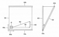
이와 관련하여, 도 6b를 참조하면, 제1 좌표축(400a)에 대해 특정 경사각(α)을 갖는 작업영역에서 로봇(10)의 구동부(13)를 제어하는 방법이 설명된다.In this regard, referring to FIG. 6B, a method of controlling the driving unit 13 of the
도 6b에 도시된 것과 같이, 작업영역의 제1 변(610a)은 경사면의 하측이고, 제2 변(610b)은 경사면의 상측일 수 있다.As shown in Fig. 6B, the
메모리(17)는 작업영역과 관련된 맵 정보(330), 로봇(10)의 주행 좌표축(400a, 400b)과 관련된 정보 등을 저장할 수 있다. 이 경우, 저장된 주행 좌표축은 상기 제1 및 제2 좌표축과 대응될 수 있다.The memory 17 may store
도 6b를 참조하면, 제어부(18)는 제1 좌표축(400a)에 대한 경사도와 관련된 정보를 이용하여, 상기 제1 좌표축(400a) 방향의 주행거리에 대한 제1 보상 값(603)을 설정할 수 있다.6B, the controller 18 may set a
예를 들어, 제어부(18)는 로봇(10)을 제1 경로(601)로 이동시키기 위하여, 작업영역의 경사도(α)를 고려하여, 제1 보상 값(603)을 설정할 수 있다. 또한, 제어부(18)는 상기 제1 보상 값(603)을 적용하여, 로봇(10)이 제2 경로(602)로 주행하도록 구동부(13)를 제어할 수 있다. 상기 로봇(10)의 구동부(13)가 제2 경로(602)로 주행하는 동안, 상기 구동부(13)에 포함된 구동바퀴에서 슬립이 발생할 수 있으며, 이로써, 상기 로봇(10)이 최종적으로 제1 경로(601)로 이동하게 된다.For example, in order to move the
한편, 메모리(17)는 상기 작업영역에 포함되는 제1 및 제2 기준 좌표정보를 저장할 수 있다. 또한, 센싱부(14)는 상기 로봇(10)이 이동함에 따라, 상기 로봇(10)의 위치 변화와 관련된 정보를 감지할 수 있다.Meanwhile, the memory 17 may store first and second reference coordinate information included in the working area. The sensing unit 14 may sense information related to a change in the position of the
이 경우, 제어부(18)는, 상기 로봇이 상기 제1 기준 좌표정보에 대응하는 위치에서, 상기 제2 기준 좌표정보에 대응하는 위치로 이동하는 동안 상기 센싱부에서 감지된 상기 위치 변화와 관련된 제1 변위정보를 산출할 수 있다.In this case, the control unit 18 determines whether or not the robot is in the position corresponding to the first reference coordinate information, while the robot moves to the position corresponding to the second reference coordinate information, 1 displacement information can be calculated.
또한, 제어부(18)는 상기 제1 및 제2 기준 좌표정보의 차이와 관련된 제2 변위정보를 산출할 수 있다. 제어부(18)는 상기 산출된 제1 및 제2 변위정보를 비교하여, 상기 경사도와 관련된 오차정보를 검출할 수 있다. 이로써, 제어부(18)는 상기 검출된 오차정보를 이용하여, 상기 제1 및 제2 보상 값을 보정할 수 있다.In addition, the controller 18 may calculate second displacement information related to the difference between the first and second reference coordinate information. The control unit 18 may compare the calculated first and second displacement information to detect error information related to the inclination. Thereby, the control unit 18 can correct the first and second compensation values using the detected error information.
예를 들어, 상기 제1 기준 좌표정보는 상기 잔디 깎기 로봇의 충전장치가 설치된 위치에 대응될 수 있다. 또한, 상기 제2 기준 좌표정보는 상기 작업영역에 포함된 좌표정보 중 상기 충전장치가 설치된 위치에서 가장 멀리 이격된 위치에 대응될 수 있다.For example, the first reference coordinate information may correspond to a position where the charging device of the lawnmower robot is installed. The second reference coordinate information may correspond to a position of the coordinate information included in the working area that is farthest from the position where the charging device is installed.
이 경우, 상기 제어부(18)는, 로봇(10)이 상기 제1 기준 좌표정보에 대응하는 위치에서 상기 제2 기준 좌표정보에 대응하는 위치로 이동하는 경우, 작업영역의 윤곽선에 설치된 와이어를 따라 이동하도록 상기 구동부를 제어할 수 있다.In this case, when the
또 다른 예에서, 상기 구동부(13)는 상기 작업영역 중 적어도 일부의 영역에서 상기 제1 및 제2 좌표축(400a, 400b) 중 적어도 하나에 대해 지그재그 주행을 수행할 수 있다.In another example, the driving unit 13 may perform zigzag running on at least one of the first and second coordinate
이 경우, 제어부(18)는, 상기 지그재그 주행에 따라, 상기 일부의 영역에 대한 상기 제1 및 제2 보상 값을 반복적으로 재설정할 수 있다.In this case, the control unit 18 can repeatedly reset the first and second compensation values for the partial area in accordance with the zigzag running.
한편, 상기 메모리(17)는 상기 작업영역에 포함되는 복수의 3차원 좌표정보로 형성되는 맵 정보를 저장할 수 있다.Meanwhile, the memory 17 may store map information formed of a plurality of three-dimensional coordinate information included in the working area.
이 경우, 상기 제어부(18)는, 상기 복수의 3차원 좌표정보를 이용하여, 상기 작업영역 중 적어도 일부 영역의 경사도와 관련된 정보를 검출할 수 있다. 제어부(18)는 상기 로봇(10)이 상기 일부 영역에 진입하면, 상기 경사도와 관련된 정보에 근거하여, 상기 구동부를 제어할 수 있다.In this case, the control unit 18 can detect information related to the inclination of at least a part of the working area using the plurality of three-dimensional coordinate information. When the
도 6c에 도시된 것과 같이, 제어부(18)는, 작업영역이 복수의 영역(S1a, S1b)으로 분할되도록 상기 복수의 영역과 관련된 정보를 설정할 수 있다. 제어부(18)는 상기 복수의 영역 별로 상기 경사도와 관련된 정보를 검출할 수 있다.As shown in Fig. 6C, the control unit 18 can set information related to the plurality of areas such that the working area is divided into a plurality of areas S1a and S1b. The control unit 18 may detect information related to the inclination by the plurality of areas.
제어부(18)는 상기 분할된 복수의 영역 중 어느 하나의 윤곽선으로부터 소정의 추가 주행거리만큼 이격된 영역까지, 기 설정된 이동 패턴에 따라, 상기 본체가 이동하도록 상기 구동부를 제어할 수 있다.The control unit 18 can control the driving unit to move the main body according to a predetermined movement pattern from an outline of any one of the divided plurality of areas to a region spaced apart by a predetermined additional driving distance.
구제척으로, 제어부(18)는 상기 검출된 경사도와 관련된 정보를 이용하여, 상기 추가 주행거리를 변경시킬 수 있다.As a remedy, the control unit 18 can change the additional mileage using information related to the detected slope.
도 6c에 도시된 것과 같이, 작업영역의 제1 변(610a)이 경사면 하측이고, 제2 변(610b)dl 경사면 상측인 경우, 제어부(18)는 작업영역에 포함되는 제1 영역(S1a)에 대응하는 경사도와 관련된 정보를 검출할 수 있다.6C, when the
아울러, 제어부(18)는 제1 영역(S1a)에 대해 작업 수행을 하는 경우, 상기 제1 영역의 경계선(450)으로부터 추가 주행거리(r')만큼 이격된 영역까지 로봇(10)을 기 설정된 이동 패턴으로 이동시킬 수 있다.The control unit 18 may set the
예를 들어, 도 6c와 도 4g를 비교하면, 경사면을 갖는 작업영역에서의 추가 주행거리(r', 도 6c 참조)가 평지인 작업영역에서의 추가 주행거리(r, 도 4g 참조)보다 길게 설정될 수 있다.For example, comparing FIG. 6C and FIG. 4G, it can be seen that the additional travel distance r '(see FIG. 6C) in the work area having the inclined plane is longer than the additional travel distance r in the flat work area Can be set.
이하의 도 7a 및 도 7b에서는 본 발명에 따른 이동 로봇의 작업영역 내에 장애물 존재 여부를 판단하는 방법의 일 실시예가 설명된다.7A and 7B, an embodiment of a method for determining the presence or absence of an obstacle in the working area of the mobile robot according to the present invention will be described.
도 7a에 도시된 것과 같이, 메모리(17)는 로봇(10)의 이동 이력과 관련된 정보를 저장할 수 있다(S701).As shown in Fig. 7A, the memory 17 may store information related to the movement history of the robot 10 (S701).
구체적으로, 제어부(18)는 소정의 시간 간격마다 구동부(13)의 작동 상태와 관련된 정보를 이용하여, 상기 로봇(10)의 이동 이력과 관련된 정보를 생성할 수 있고, 상기 생성된 정보가 저장되도록 상기 메모리(17)를 제어할 수 있다.Specifically, the control unit 18 can generate information related to the movement history of the
예를 들어, 제어부(18)는 로봇(10)의 주행 방향이 변경될 때마다, 변경 직전의 로봇(10)의 이동 거리, 이동 방향, 이동 시작 지점과 관련된 정보를 검출할 수 있고, 상기 검출된 정보들을 로봇(10)의 이동 이력과 관련된 정보로 메모리(17)에 저장할 수 있다.For example, the control unit 18 can detect information related to the movement distance, the movement direction, and the movement start point of the
다음으로, 제어부(18)는 상기 로봇(10)의 이동 이력과 관련된 정보에 근거하여, 작업영역 중 적어도 일부 영역에 장애물이 존재하는지 여부를 판단할 수 있다(S702).Next, the control unit 18 can determine whether or not an obstacle exists in at least a part of the work area based on the information related to the movement history of the robot 10 (S702).
이와 관련하여, 도 7b를 참조하면, 구동부(13)는 작업영역 내에서 기 설정된 이동 패턴에 근거하여 로봇(10)을 이동시키도록 작동할 수 있다. 이하의 도 7b에서는 제1 주행축(400b) 방향으로 진행하며, 지그재그로 주행을 수행하는 구동부(13)를 포함하는 로봇(10)과 관련된 일 실시예가 설명된다. In this regard, referring to FIG. 7B, the driving unit 13 may operate to move the
메모리(17)는 구동부(13)의 제1 주행(701, 702)에 대응하여, 로봇(10)의 이동 이력과 관련된 정보를 저장할 수 있다.The memory 17 may store information related to the movement history of the
제어부(18)는 제1 주행(701, 702) 이후에, 제1 주행보다 이동 거리가 짧은 로봇(10)의 제2 주행(703, 704)이 소정의 기준 횟수 이상 발생하고, 상기 제2 주행 이후에, 상기 제2 주행보다 이동 거리가 긴 로봇(10)의 제3 주행(705)이 발생하는 경우, 작업영역 중 적어도 일부 영역에 장애물이 존재하는 것으로 판단할 수 있다.The controller 18 determines that the second travels 703 and 704 of the
이 경우, 상기 기준 횟수는 사용자 입력에 근거하여 변경될 수 있다.In this case, the reference number may be changed based on user input.
다음으로, 제어부(18)는 상기 일부 영역에 장애물이 존재하는 것으로 판단되면, 상기 로봇(10)의 이동 방향을 변경시키도록 구동부(13)를 제어할 수 있다(S703).Next, if it is determined that an obstacle exists in the partial area, the control unit 18 may control the driving unit 13 to change the moving direction of the robot 10 (S703).
구체적으로, 도 7b를 참조하면, 로봇(10)은 제1 좌표축(400a)의 양의 방향으로 진행하며, 지그재그로 주행할 수 있다. 즉, 로봇(10)은 제1 주행(701, 702), 제2 주행(703, 704) 및 제3 주행(705)을 순차적으로 수행할 수 있다. Specifically, referring to FIG. 7B, the
이 경우, 위에 설명한 것과 같이, 제어부(18)가 작업영역의 일부 영역에 장애물(700)이 존재하는 것으로 판단하는 경우, 로봇(10)이 제1 좌표축(400a)의 음의 방향으로 진행하기 위해, 이동 방향을 변경시키도록 구동부(13)를 제어할 수 있다.In this case, as described above, when the controller 18 determines that the
다음으로, 제어부(18)는 로봇(10)의 이동 방향이 변경된 후, 상기 로봇(10)의 주행과 관련된 정보를 이용하여, 상기 장애물의 존재와 관련된 판단결과를 검증할 수 있다(S704).Next, the control unit 18 may verify the determination result related to the presence of the obstacle by using the information related to the running of the
구체적으로, 도 7b를 참조하면, 로봇(10)의 이동 방향이 변경된 후, 구동부(13)는 제4 주행(706)을 수행할 수 있다. 제어부(18)는 상기 수행된 제4 주행(706)의 종점과 관련된 좌표정보와, 상기 제2 주행(704)의 종점과 관련된 좌표정보를 비교하여, 상기 장애물(700)의 존재와 관련된 판단결과를 검증할 수 있다.Specifically, referring to FIG. 7B, after the moving direction of the
즉, 제어부(18)는 제4 주행(706)의 종점과 관련된 좌표정보의 제2 좌표축(400b) 성분이, 상기 제2 주행(704)의 종점과 관련된 좌표정보의 제2 좌표축(400b) 성분 보다 큰 경우, 상기 장애물(700)의 존재와 관련된 판단결과를 검증할 수 있다.That is, the control unit 18 determines that the second coordinate
다음으로, 제어부(18)는 상기 검증결과에 근거하여, 구동부(13)를 제어할 수 있다(S705).Next, the control unit 18 can control the driving unit 13 based on the verification result (S705).
구체적으로, 제어부(18)는 장애물이 존재하는 것으로 검증되면, 제2 주행과 관련된 정보를 이용하여, 로봇(10)을 특정 위치로 이동시킨 후, 절삭 작업을 재개하도록 구동부(13)를 제어할 수 있다. 도 7b를 참조하면, 제어부(18)는 장애물이 존재하는 것으로 검증되면, 제2 주행(703)과 관련된 이력 정보를 이용하여, 상기 검증된 장애물에 의해 로봇이 절삭 작업을 수행하지 못한 영역에 대해 절삭 작업을 재개하도록, 로봇(10)을 특정 위치로 이동시킬 수 있다. 예를 들어, 상기 특정 위치는 작업영역의 윤곽선에 설치된 와이어 중 제2 주행(703)의 제2 주행 좌표축 좌표정보에 대응하는 위치일 수 있다.Specifically, when it is verified that an obstacle exists, the controller 18 moves the
또한, 제어부(18)는 장애물이 존재하지 않는 것으로 검증되면, 상기 변경된 이동 방향을 변경되기 전으로 다시 변경하여, 기 설정된 이동 패턴에 따라 로봇(10)이 이동되도록 구동부(13)를 제어할 수 있다.If it is verified that an obstacle does not exist, the control unit 18 may change the changed moving direction again before changing the moving direction so as to control the driving unit 13 to move the
본 발명에 따르면, 잔디 깎기 로봇의 작업영역 내에서, 잔디가 절삭되지 않는 부분을 최소화시킬 수 있는 효과가 도출된다.According to the present invention, within the working area of the lawn mower robot, an effect is obtained in which the portion where lawn is not cut can be minimized.
또한 본 발명에 따르면, 잔디 깎기 로봇의 작업 효율을 증대시킬 수 있다.Further, according to the present invention, the working efficiency of the lawn mower robot can be increased.
또한 본 발명에 따르면, 잔디 깎기 로봇에 저장되는 작업영역과 관련된 맵 정보의 정확도를 향상시킬 수 있다.Further, according to the present invention, it is possible to improve the accuracy of the map information related to the work area stored in the lawn mower.
또한 본 발명에 따르면, 잔디 깎기 로봇의 전력공급을 자동화할 수 있고, 잔디 깎기 로봇에서 발생하는 다양한 오류를 방지할 수 있다.Further, according to the present invention, it is possible to automate the power supply of the lawn mower robot and prevent various errors occurring in the lawn mower.
본 발명은 본 발명의 정신 및 필수적 특징을 벗어나지 않는 범위에서 다른 특정한 형태로 구체화될 수 있음은 당업자에게 자명하다. 따라서, 상기의 상세한 설명은 모든 면에서 제한적으로 해석되어서는 아니되고 예시적인 것으로 고려되어야 한다. 본 발명의 범위는 첨부된 청구항의 합리적 해석에 의해 결정되어야 하고, 본 발명의 등가적 범위 내에서의 모든 변경은 본 발명의 범위에 포함된다.It will be apparent to those skilled in the art that the present invention may be embodied in other specific forms without departing from the spirit or essential characteristics thereof. Accordingly, the above description should not be construed in a limiting sense in all respects and should be considered illustrative. The scope of the present invention should be determined by rational interpretation of the appended claims, and all changes within the scope of equivalents of the present invention are included in the scope of the present invention.
Claims (8)
상기 본체가 작업영역 내부에서 이동하도록 구동되는 구동부;
상기 본체의 자세와 관련된 정보를 감지하는 센싱부; 및
상기 감지된 본체의 자세와 관련된 정보를 이용하여, 상기 본체의 현재 위치에 대응하는 경사도와 관련된 정보를 검출하고,
상기 검출된 경사도와 관련된 정보에 근거하여, 상기 구동부를 제어하는 제어부를 포함하는 것을 특징으로 하는 잔디 깎기 로봇.main body;
A driving unit driven to move the main body within the working area;
A sensing unit sensing information related to the posture of the main body; And
Detecting information related to an inclination corresponding to a current position of the main body using information related to the detected attitude of the main body,
And a control unit for controlling the driving unit based on information related to the detected inclination.
상기 작업영역에 대한 제1 및 제2 좌표축과 관련된 정보를 저장하는 메모리를 더 포함하고,
상기 제어부는,
상기 경사도와 관련된 정보를 이용하여, 상기 제1 좌표축 방향의 주행거리에 대한 제1 보상 값과, 상기 제2 좌표축 방향의 주행거리에 대한 제2 보상 값을 설정하고,
상기 설정된 제1 및 제2 보상 값을 이용하여, 상기 구동부를 제어하는 것을 특징으로 하는 잔디 깎기 로봇.The method according to claim 1,
Further comprising a memory for storing information associated with the first and second coordinate axes for the work area,
Wherein,
Setting a first compensation value for a travel distance in the first coordinate axis direction and a second compensation value for a travel distance in the second coordinate axis direction using information related to the inclination,
And controls the driving unit using the set first and second compensation values.
상기 메모리는 상기 작업영역에 포함되는 제1 및 제2 기준 좌표정보를 저장하고,
상기 센싱부는 상기 본체가 이동함에 따라, 상기 본체의 위치 변화와 관련된 정보를 감지하고,
상기 제어부는,
상기 본체가 상기 제1 기준 좌표정보에 대응하는 위치에서, 상기 제2 기준 좌표정보에 대응하는 위치로 이동하는 동안 상기 센싱부에서 감지된 상기 위치 변화와 관련된 제1 변위정보를 산출하고,
상기 제1 및 제2 기준 좌표정보의 차이와 관련된 제2 변위정보를 산출하고,
상기 산출된 제1 및 제2 변위정보를 비교하여, 상기 경사도와 관련된 오차정보를 검출하고,
상기 검출된 오차정보를 이용하여, 상기 제1 및 제2 보상 값을 보정하는 것을 특징으로 하는 잔디 깎기 로봇.3. The method of claim 2,
Wherein the memory stores first and second reference coordinate information included in the working area,
The sensing unit senses information related to a positional change of the main body as the main body moves,
Wherein,
Calculating a first displacement information related to the positional change sensed by the sensing unit while the main body moves to a position corresponding to the second reference coordinate information at a position corresponding to the first reference coordinate information,
Calculating second displacement information related to the difference between the first and second reference coordinate information,
Comparing the calculated first and second displacement information to detect error information related to the inclination,
And corrects the first and second compensation values using the detected error information.
상기 제1 기준 좌표정보는 상기 잔디 깎기 로봇의 충전장치가 설치된 위치에 대응되고,
상기 제2 기준 좌표정보는 상기 작업영역에 포함된 좌표정보 중 상기 충전장치가 설치된 위치에서 가장 멀리 이격된 위치에 대응되고,
상기 제어부는,
상기 본체가 상기 제1 기준 좌표정보에 대응하는 위치에서 상기 제2 기준 좌표정보에 대응하는 위치로 이동하는 경우, 상기 작업영역의 윤곽선에 설치된 와이어를 따라 이동하도록 상기 구동부를 제어하는 것을 특징으로 하는 잔디 깎기 로봇.The method of claim 3,
Wherein the first reference coordinate information corresponds to a position where the charging device of the lawnmower robot is installed,
Wherein the second reference coordinate information corresponds to a position that is farthest from the coordinate information included in the working area at a position where the charging device is installed,
Wherein,
When the main body moves to a position corresponding to the second reference coordinate information at a position corresponding to the first reference coordinate information, controls the driving unit to move along the wire provided on the contour of the working area Lawn mower robot.
상기 구동부는 상기 작업영역 중 적어도 일부의 영역에서 상기 제1 및 제2 좌표축 중 적어도 하나에 대해 지그재그 주행을 수행하고,
상기 제어부는,
상기 지그재그 주행에 따라, 상기 일부의 영역에 대한 상기 제1 및 제2 보상 값을 반복적으로 재설정하는 것을 특징으로 하는 잔디 깎기 로봇.3. The method of claim 2,
Wherein the driving unit performs zigzag running on at least one of the first and second coordinate axes in at least a part of the working area,
Wherein,
And repeatedly resetting the first and second compensation values for the part of the area in accordance with the zigzag running.
상기 작업영역에 포함되는 복수의 3차원 좌표정보로 형성되는 맵 정보를 저장하는 메모리를 더 포함하고,
상기 제어부는,
상기 복수의 3차원 좌표정보를 이용하여, 상기 작업영역 중 적어도 일부 영역의 경사도와 관련된 정보를 검출하고,
상기 본체가 상기 일부 영역에 진입하면, 상기 경사도와 관련된 정보에 근거하여, 상기 구동부를 제어하는 것을 특징으로 하는 잔디 깎기 로봇.The method according to claim 1,
And a memory for storing map information formed of a plurality of three-dimensional coordinate information included in the working area,
Wherein,
Detecting information related to an inclination of at least a part of the working area using the plurality of three-dimensional coordinate information,
Wherein the controller controls the driving unit based on information related to the inclination when the main body enters the partial area.
상기 제어부는,
상기 작업영역이 복수의 영역으로 분할되도록 상기 복수의 영역과 관련된 정보를 설정하고,
상기 복수의 영역 별로 상기 경사도와 관련된 정보를 검출하고,
상기 분할된 복수의 영역 중 어느 하나의 윤곽선으로부터 소정의 추가 주행거리만큼 이격된 영역까지, 기 설정된 이동 패턴에 따라, 상기 본체가 이동하도록 상기 구동부를 제어하고,
상기 검출된 경사도와 관련된 정보를 이용하여, 상기 추가 주행거리를 변경시키는 것을 특징으로 하는 잔디 깎기 로봇.The method according to claim 1,
Wherein,
Setting information related to the plurality of areas such that the working area is divided into a plurality of areas,
Detecting information related to the inclination for each of the plurality of areas,
Controls the driving unit to move the main body according to a predetermined movement pattern from an outline of any one of the plurality of divided regions to a region spaced apart by a predetermined additional driving distance,
And changes the additional mileage using information related to the detected slope.
상기 잔디 깎기 로봇의 자세와 관련된 정보를 감지하는 단계;
상기 감지된 잔디 깎기 로봇의 자세와 관련된 정보를 이용하여, 상기 잔디 깎기 로봇의 현재 위치에 대응하는 경사도와 관련된 정보를 검출하는 단계; 및
상기 검출된 경사도와 관련된 정보에 근거하여, 상기 잔디 깎기 로봇의 구동부를 제어하는 단계를 포함하는 것을 특징으로 하는 잔디 깎기 로봇의 제어방법.A control method of a lawn mower robot,
Sensing information related to the posture of the lawnmower robot;
Detecting information related to an inclination corresponding to a current position of the lawn mower using information related to the detected posture of the lawn mower robot; And
And controlling the driving unit of the lawn mower robot based on information related to the detected inclination.
Priority Applications (1)
| Application Number | Priority Date | Filing Date | Title |
|---|---|---|---|
| KR1020150059975A KR102488523B1 (en) | 2015-04-28 | 2015-04-28 | Moving robot and controlling method thereof |
Applications Claiming Priority (1)
| Application Number | Priority Date | Filing Date | Title |
|---|---|---|---|
| KR1020150059975A KR102488523B1 (en) | 2015-04-28 | 2015-04-28 | Moving robot and controlling method thereof |
Publications (2)
| Publication Number | Publication Date |
|---|---|
| KR20160128126A true KR20160128126A (en) | 2016-11-07 |
| KR102488523B1 KR102488523B1 (en) | 2023-01-13 |
Family
ID=57529848
Family Applications (1)
| Application Number | Title | Priority Date | Filing Date |
|---|---|---|---|
| KR1020150059975A Active KR102488523B1 (en) | 2015-04-28 | 2015-04-28 | Moving robot and controlling method thereof |
Country Status (1)
| Country | Link |
|---|---|
| KR (1) | KR102488523B1 (en) |
Cited By (4)
| Publication number | Priority date | Publication date | Assignee | Title |
|---|---|---|---|---|
| KR20190098866A (en) * | 2018-02-02 | 2019-08-23 | 엘지전자 주식회사 | Moving robot |
| WO2019194634A1 (en) * | 2018-04-06 | 2019-10-10 | 엘지전자 주식회사 | Mobile robot and mobile robot system |
| CN114789439A (en) * | 2021-01-26 | 2022-07-26 | 深圳市普渡科技有限公司 | Slope positioning correction method and device, robot and readable storage medium |
| CN116088509A (en) * | 2022-12-28 | 2023-05-09 | 深圳优艾智合机器人科技有限公司 | Mobile robot management and control method, mobile robot and readable storage medium |
Citations (4)
| Publication number | Priority date | Publication date | Assignee | Title |
|---|---|---|---|---|
| JP2729508B2 (en) * | 1989-04-28 | 1998-03-18 | ヤンマーディーゼル株式会社 | Unmanned vehicle movement control method |
| KR20130015458A (en) * | 2011-08-03 | 2013-02-14 | 엘지전자 주식회사 | Lawn mower robot system and control method for the same |
| US20130218397A1 (en) * | 2010-07-28 | 2013-08-22 | Active S.R.L. | Method and system for controlling a self-propelled robot device |
| KR20150005809A (en) * | 2013-07-05 | 2015-01-15 | 한국전자통신연구원 | Method and apparatus for controlling driving of robot |
-
2015
- 2015-04-28 KR KR1020150059975A patent/KR102488523B1/en active Active
Patent Citations (4)
| Publication number | Priority date | Publication date | Assignee | Title |
|---|---|---|---|---|
| JP2729508B2 (en) * | 1989-04-28 | 1998-03-18 | ヤンマーディーゼル株式会社 | Unmanned vehicle movement control method |
| US20130218397A1 (en) * | 2010-07-28 | 2013-08-22 | Active S.R.L. | Method and system for controlling a self-propelled robot device |
| KR20130015458A (en) * | 2011-08-03 | 2013-02-14 | 엘지전자 주식회사 | Lawn mower robot system and control method for the same |
| KR20150005809A (en) * | 2013-07-05 | 2015-01-15 | 한국전자통신연구원 | Method and apparatus for controlling driving of robot |
Cited By (8)
| Publication number | Priority date | Publication date | Assignee | Title |
|---|---|---|---|---|
| KR20190098866A (en) * | 2018-02-02 | 2019-08-23 | 엘지전자 주식회사 | Moving robot |
| US11169542B2 (en) | 2018-02-02 | 2021-11-09 | Lg Electronics Inc. | Moving robot |
| WO2019194634A1 (en) * | 2018-04-06 | 2019-10-10 | 엘지전자 주식회사 | Mobile robot and mobile robot system |
| KR20190124138A (en) * | 2018-04-06 | 2019-11-04 | 엘지전자 주식회사 | Moving robot and Moving robot system |
| US11960289B2 (en) | 2018-04-06 | 2024-04-16 | Lg Electronics Inc. | Moving robot and moving robot system |
| CN114789439A (en) * | 2021-01-26 | 2022-07-26 | 深圳市普渡科技有限公司 | Slope positioning correction method and device, robot and readable storage medium |
| CN114789439B (en) * | 2021-01-26 | 2024-03-19 | 深圳市普渡科技有限公司 | Slope positioning correction method, device, robot and readable storage medium |
| CN116088509A (en) * | 2022-12-28 | 2023-05-09 | 深圳优艾智合机器人科技有限公司 | Mobile robot management and control method, mobile robot and readable storage medium |
Also Published As
| Publication number | Publication date |
|---|---|
| KR102488523B1 (en) | 2023-01-13 |
Similar Documents
| Publication | Publication Date | Title |
|---|---|---|
| KR20160128124A (en) | Moving robot and controlling method thereof | |
| KR20160128123A (en) | Moving robot and controlling method thereof | |
| US11044845B2 (en) | Moving robot and control method thereof | |
| EP3494769B1 (en) | Mobile robot and control method thereof | |
| EP3168705B1 (en) | Domestic robotic system | |
| EP3238524B1 (en) | Moving robot and control method thereof | |
| EP1975046B1 (en) | Legged locomotion robot | |
| US20090093907A1 (en) | Robot System | |
| US11852484B2 (en) | Method for determining the orientation of a robot, orientation determination apparatus of a robot, and robot | |
| JP2012105557A (en) | Automatic lawn mower | |
| US20130166137A1 (en) | Mobile apparatus and localization method thereof | |
| KR20180039477A (en) | Method and apparatus for planning path | |
| JP6845342B2 (en) | Utility pole management system | |
| WO2020093970A1 (en) | Automated lawnmower and control method therefor | |
| KR20160128126A (en) | Moving robot and controlling method thereof | |
| EP4006682B1 (en) | Autonomous work machine, autonomous work machine control method and program | |
| JP2017227463A (en) | Position and attitude determination device | |
| KR101242253B1 (en) | Method for building an elevation map with elevation information baded on terrain classification and matching strategy | |
| JP5439552B2 (en) | Robot system | |
| CN112082542A (en) | Digital model correction | |
| JP6982105B2 (en) | Working machine | |
| CN114593726B (en) | Path smoothing method and device | |
| JP7573826B1 (en) | Information processing system, information processing method, and program | |
| CN117589153B (en) | Map updating method and robot | |
| Podsedkowski et al. | Online navigation of mobile robots using laser scanner |
Legal Events
| Date | Code | Title | Description |
|---|---|---|---|
| PA0109 | Patent application |
St.27 status event code: A-0-1-A10-A12-nap-PA0109 |
|
| PN2301 | Change of applicant |
St.27 status event code: A-3-3-R10-R13-asn-PN2301 St.27 status event code: A-3-3-R10-R11-asn-PN2301 |
|
| PG1501 | Laying open of application |
St.27 status event code: A-1-1-Q10-Q12-nap-PG1501 |
|
| P22-X000 | Classification modified |
St.27 status event code: A-2-2-P10-P22-nap-X000 |
|
| A201 | Request for examination | ||
| PA0201 | Request for examination |
St.27 status event code: A-1-2-D10-D11-exm-PA0201 |
|
| PN2301 | Change of applicant |
St.27 status event code: A-3-3-R10-R13-asn-PN2301 St.27 status event code: A-3-3-R10-R11-asn-PN2301 |
|
| E902 | Notification of reason for refusal | ||
| PE0902 | Notice of grounds for rejection |
St.27 status event code: A-1-2-D10-D21-exm-PE0902 |
|
| E13-X000 | Pre-grant limitation requested |
St.27 status event code: A-2-3-E10-E13-lim-X000 |
|
| P11-X000 | Amendment of application requested |
St.27 status event code: A-2-2-P10-P11-nap-X000 |
|
| P13-X000 | Application amended |
St.27 status event code: A-2-2-P10-P13-nap-X000 |
|
| E90F | Notification of reason for final refusal | ||
| PE0902 | Notice of grounds for rejection |
St.27 status event code: A-1-2-D10-D21-exm-PE0902 |
|
| P11-X000 | Amendment of application requested |
St.27 status event code: A-2-2-P10-P11-nap-X000 |
|
| P13-X000 | Application amended |
St.27 status event code: A-2-2-P10-P13-nap-X000 |
|
| E701 | Decision to grant or registration of patent right | ||
| PE0701 | Decision of registration |
St.27 status event code: A-1-2-D10-D22-exm-PE0701 |
|
| GRNT | Written decision to grant | ||
| PR0701 | Registration of establishment |
St.27 status event code: A-2-4-F10-F11-exm-PR0701 |
|
| PR1002 | Payment of registration fee |
St.27 status event code: A-2-2-U10-U11-oth-PR1002 Fee payment year number: 1 |
|
| PG1601 | Publication of registration |
St.27 status event code: A-4-4-Q10-Q13-nap-PG1601 |
|
| PR1001 | Payment of annual fee |
St.27 status event code: A-4-4-U10-U11-oth-PR1001 Fee payment year number: 4 |
|
| U11 | Full renewal or maintenance fee paid |
Free format text: ST27 STATUS EVENT CODE: A-4-4-U10-U11-OTH-PR1001 (AS PROVIDED BY THE NATIONAL OFFICE) Year of fee payment: 4 |