KR20160097237A - Coupling - Google Patents
Coupling Download PDFInfo
- Publication number
- KR20160097237A KR20160097237A KR1020167017102A KR20167017102A KR20160097237A KR 20160097237 A KR20160097237 A KR 20160097237A KR 1020167017102 A KR1020167017102 A KR 1020167017102A KR 20167017102 A KR20167017102 A KR 20167017102A KR 20160097237 A KR20160097237 A KR 20160097237A
- Authority
- KR
- South Korea
- Prior art keywords
- pair
- members
- coupling
- axis
- axes
- Prior art date
Links
Images


Classifications
-
- F—MECHANICAL ENGINEERING; LIGHTING; HEATING; WEAPONS; BLASTING
- F16—ENGINEERING ELEMENTS AND UNITS; GENERAL MEASURES FOR PRODUCING AND MAINTAINING EFFECTIVE FUNCTIONING OF MACHINES OR INSTALLATIONS; THERMAL INSULATION IN GENERAL
- F16D—COUPLINGS FOR TRANSMITTING ROTATION; CLUTCHES; BRAKES
- F16D3/00—Yielding couplings, i.e. with means permitting movement between the connected parts during the drive
- F16D3/16—Universal joints in which flexibility is produced by means of pivots or sliding or rolling connecting parts
- F16D3/20—Universal joints in which flexibility is produced by means of pivots or sliding or rolling connecting parts one coupling part entering a sleeve of the other coupling part and connected thereto by sliding or rolling members
- F16D3/202—Universal joints in which flexibility is produced by means of pivots or sliding or rolling connecting parts one coupling part entering a sleeve of the other coupling part and connected thereto by sliding or rolling members one coupling part having radially projecting pins, e.g. tripod joints
- F16D3/205—Universal joints in which flexibility is produced by means of pivots or sliding or rolling connecting parts one coupling part entering a sleeve of the other coupling part and connected thereto by sliding or rolling members one coupling part having radially projecting pins, e.g. tripod joints the pins extending radially outwardly from the coupling part
- F16D3/2052—Universal joints in which flexibility is produced by means of pivots or sliding or rolling connecting parts one coupling part entering a sleeve of the other coupling part and connected thereto by sliding or rolling members one coupling part having radially projecting pins, e.g. tripod joints the pins extending radially outwardly from the coupling part having two pins
-
- F—MECHANICAL ENGINEERING; LIGHTING; HEATING; WEAPONS; BLASTING
- F16—ENGINEERING ELEMENTS AND UNITS; GENERAL MEASURES FOR PRODUCING AND MAINTAINING EFFECTIVE FUNCTIONING OF MACHINES OR INSTALLATIONS; THERMAL INSULATION IN GENERAL
- F16D—COUPLINGS FOR TRANSMITTING ROTATION; CLUTCHES; BRAKES
- F16D3/00—Yielding couplings, i.e. with means permitting movement between the connected parts during the drive
- F16D3/16—Universal joints in which flexibility is produced by means of pivots or sliding or rolling connecting parts
- F16D3/20—Universal joints in which flexibility is produced by means of pivots or sliding or rolling connecting parts one coupling part entering a sleeve of the other coupling part and connected thereto by sliding or rolling members
- F16D3/22—Universal joints in which flexibility is produced by means of pivots or sliding or rolling connecting parts one coupling part entering a sleeve of the other coupling part and connected thereto by sliding or rolling members the rolling members being balls, rollers, or the like, guided in grooves or sockets in both coupling parts
- F16D3/223—Universal joints in which flexibility is produced by means of pivots or sliding or rolling connecting parts one coupling part entering a sleeve of the other coupling part and connected thereto by sliding or rolling members the rolling members being balls, rollers, or the like, guided in grooves or sockets in both coupling parts the rolling members being guided in grooves in both coupling parts
- F16D3/224—Universal joints in which flexibility is produced by means of pivots or sliding or rolling connecting parts one coupling part entering a sleeve of the other coupling part and connected thereto by sliding or rolling members the rolling members being balls, rollers, or the like, guided in grooves or sockets in both coupling parts the rolling members being guided in grooves in both coupling parts the groove centre-lines in each coupling part lying on a sphere
-
- F—MECHANICAL ENGINEERING; LIGHTING; HEATING; WEAPONS; BLASTING
- F16—ENGINEERING ELEMENTS AND UNITS; GENERAL MEASURES FOR PRODUCING AND MAINTAINING EFFECTIVE FUNCTIONING OF MACHINES OR INSTALLATIONS; THERMAL INSULATION IN GENERAL
- F16D—COUPLINGS FOR TRANSMITTING ROTATION; CLUTCHES; BRAKES
- F16D3/00—Yielding couplings, i.e. with means permitting movement between the connected parts during the drive
- F16D3/16—Universal joints in which flexibility is produced by means of pivots or sliding or rolling connecting parts
- F16D3/26—Hooke's joints or other joints with an equivalent intermediate member to which each coupling part is pivotally or slidably connected
- F16D3/38—Hooke's joints or other joints with an equivalent intermediate member to which each coupling part is pivotally or slidably connected with a single intermediate member with trunnions or bearings arranged on two axes perpendicular to one another
- F16D3/42—Hooke's joints or other joints with an equivalent intermediate member to which each coupling part is pivotally or slidably connected with a single intermediate member with trunnions or bearings arranged on two axes perpendicular to one another with ring-shaped intermediate member provided with bearings or inwardly-directed trunnions
-
- F—MECHANICAL ENGINEERING; LIGHTING; HEATING; WEAPONS; BLASTING
- F16—ENGINEERING ELEMENTS AND UNITS; GENERAL MEASURES FOR PRODUCING AND MAINTAINING EFFECTIVE FUNCTIONING OF MACHINES OR INSTALLATIONS; THERMAL INSULATION IN GENERAL
- F16D—COUPLINGS FOR TRANSMITTING ROTATION; CLUTCHES; BRAKES
- F16D3/00—Yielding couplings, i.e. with means permitting movement between the connected parts during the drive
- F16D3/16—Universal joints in which flexibility is produced by means of pivots or sliding or rolling connecting parts
- F16D3/26—Hooke's joints or other joints with an equivalent intermediate member to which each coupling part is pivotally or slidably connected
- F16D3/44—Hooke's joints or other joints with an equivalent intermediate member to which each coupling part is pivotally or slidably connected the intermediate member being connected to the coupling parts by ridges, pins, balls, or the like guided in grooves or between cogs
-
- F—MECHANICAL ENGINEERING; LIGHTING; HEATING; WEAPONS; BLASTING
- F16—ENGINEERING ELEMENTS AND UNITS; GENERAL MEASURES FOR PRODUCING AND MAINTAINING EFFECTIVE FUNCTIONING OF MACHINES OR INSTALLATIONS; THERMAL INSULATION IN GENERAL
- F16D—COUPLINGS FOR TRANSMITTING ROTATION; CLUTCHES; BRAKES
- F16D3/00—Yielding couplings, i.e. with means permitting movement between the connected parts during the drive
- F16D3/16—Universal joints in which flexibility is produced by means of pivots or sliding or rolling connecting parts
- F16D3/26—Hooke's joints or other joints with an equivalent intermediate member to which each coupling part is pivotally or slidably connected
- F16D3/30—Hooke's joints or other joints with an equivalent intermediate member to which each coupling part is pivotally or slidably connected in which the coupling is specially adapted to constant velocity-ratio
- F16D3/32—Hooke's joints or other joints with an equivalent intermediate member to which each coupling part is pivotally or slidably connected in which the coupling is specially adapted to constant velocity-ratio by the provision of two intermediate members each having two relatively perpendicular trunnions or bearings
Abstract
커플링 장치는 부재 쌍을 포함하며, 그 중 제1 부재는 중심점에 대해 중심 맞춰지는 외부 볼록 구형 주변부 및 중심점을 통해 연장하는 비틀림 축선을 가지며, 제2 환형 부재는 중심점에 중심 맞춰지고 내부 제1 부재의 외부 주변부와 상보적인 내부 오목 구형 주변부를 가진다. 내부 부재 및 외부 부재의 구형 표면은 그 사이로 반경 방향 하중을 전달하고 그 사이로 비틀림 축선을 따라 작용하는 하중을 전달하도록 공동 작용한다. 축선 배열은 중심점의 반경 방향으로 연장하며 하나로부터 다른 하나로 비틀림 하중을 전달하기 위한 제1 및 제2 환형 부재를 커플링한다. 부재 쌍의 각각의 부재는 축선 배열에 의해 강요되는 방향으로 상기 중심 점을 중심으로 서로에 대해 회전될 수 있다.The coupling device includes a pair of members, the first member having an outer convex spherical periphery centered about a center point and a torsion axis extending through a center point, the second annular member centered on a center point, And an inner concave peripheral portion complementary to the outer peripheral portion of the member. The spherical surface of the inner member and the outer member cooperate to transmit a radial load therebetween and to transmit a load therebetween acting along the torsional axis. The axial arrangement extends in the radial direction of the center point and couples the first and second annular members for transmitting a torsional load from one to another. Each member of the pair of members can be rotated about each other about the center point in a direction imposed by the axial arrangement.
Description
본 발명은 커플링에 관한 것이다.The present invention relates to couplings.
기계적 커플링이 주지되어 있다. 예에는 각도 오정렬된 축, 유니버설 조인트, 등속 조인트를 커플링하기 위한 커플링, 구동축을 피동축에 커플링하기 위한 커플링, 토크 축을 예를 들어, 서스펜션 시스템의 구조적 요소에 연결하기 위한 커플링을 포함한다.Mechanical coupling is well known. Examples include angled misaligned shafts, universal joints, couplings for coupling constant-velocity joints, couplings for coupling the drive shaft to the driven shaft, couplings for connecting the torque axis to structural elements of the suspension system, for example .
본 발명에 따라서 커플링은 내부 부재와 외부 환형 부재를 가지며 그리고According to the invention, the coupling has an inner member and an outer annular member,
- 최내부 및 최외부 부재 중 하나 또는 모두를 포함하거나 포함하지 않을 수 있는 하나 이상의 부재 쌍을 포함하며, 각각의 부재 쌍은 공통 축선을 가지고 그 공통 축선 상에 공통 제1 중심을 가지는 제1 및 제2 환형 부재이며;- at least one pair of members, which may or may not include one or both of the innermost and outermost members, wherein each pair of members comprises a first and a second member having a common axis and a common first center on its common axis, A second annular member;
- 제1 부재는 외부의 볼록한 구형 주변부를 가지며,The first member has an outer convex spherical periphery,
- 제2 환형 부재는 제1 환형 부재의 외부의 볼록한 주변부가 내부에 수용되는 내부의 오목한 구형 주변부를 가지며,The second annular member has an inner, concave spherical periphery in which the convex periphery of the outside of the first annular member is received therein,
- 외부의 볼록한 주변부와 내부의 오목한 주변부는 제1 중심에 대해 동심이고 서로에 대해 상보적이며 그들 사이의 비틀림 축선을 따라 작용하는 축방향 하중을 전달하도록 서로 공동-작용하며,The outer convex periphery and the inner concave periphery cooperate with each other to concentrate with respect to the first center and are complementary to each other and to transmit an axial load acting along a torsional axis therebetween,
- 하나 또는 정반대의 축선 쌍이 부재의 하나로부터 다른 하나로 비틀림 하중을 전달하기 위해서 제1 부재와 제2 부재를 커플링하는 부재 쌍의 공통 중심의 반경 방향으로 배치되며, 제1 및 제2 환형 부재가 축선(들) 주위에서 서로에 대해 회전될 수 있도록 축선(들)에 의해 강요된다.The first and second annular members are arranged in the radial direction of the common center of the pair of members coupling the first member and the second member to transmit a torsional load from one of the members to the other, Are forced by the axis (s) so that they can be rotated about each other about the axis (s).
가장 실용적인 용례를 위해서, 외부 부재 이외의 상기 부재는 공통 중심을 포함하는 구형 부분(segment)을 포함한다. 구형 부분은 평행한 평면 쌍 사이에 있는 구의 일부이다. 그러나 몇몇 상황에서, 평면이 평행하지 않고 교차하지 않거나 그의 정점이 공통 축선 상에 있는 원뿔에 의해 절단되는 상황에서 구형 부분이 사용되는 상황을 고려할 수 있다 - 그러한 대안은 제작, 조립 및 사용 모두에 단점을 가질 수 있으며 채택하는 것이 쉽지 않을 것으로 보인다.For the most practical application, the member other than the outer member comprises a spherical segment comprising a common center. The spherical part is part of a sphere between pairs of parallel planes. However, in some situations, it can be taken into account that a spherical part is used in a situation where the plane is not parallel and does not intersect or its apex is cut off by a cone on a common axis - such an alternative has drawbacks both in fabrication, And it is not likely to be easy to adopt.
내부 부재 및 외부 환형 부재는 적어도 하나의 축선에 의해 커플링되는 부재 쌍을 포함할 수 있거나, 내부 부재와 외부 부재 사이에 배치되는 하나 이상의 중간 부재가 있을 수 있으며, 각각의 인접한 부재 쌍은 축선에 의해 커플링되는 부재 쌍을 포함한다.The inner member and the outer annular member may include a pair of members coupled by at least one axis or may have one or more intermediate members disposed between the inner member and the outer member, Lt; RTI ID = 0.0 > a < / RTI >
축선(들)은 토크를 지지하며 제1 및 제2 부재의 구형 표면은 축 방향 및 반경 방향 하중을 지지한다. 임의의 축 방향 하중의 대부분은 구형 표면에 의해 지지된다. 축선(들)은 또한 축 방향 하중의 일부를 지지할 수 있다. 반경 방향 및 축 방향 하중은 비틀림 하중에서 분리된다. 실시예에서, 축선(들)은 반경 방향 하중이 축선에 의해 지지되지 않도록 그에 의해 커플링되는 부재들 사이로 반경 방향 하중을 전달하지 않도록 구성된다. 따라서 반경 방향 하중은 구형 표면에 의해 대부분 또는 전체가 지지된다.The axis (s) support the torque and the spherical surfaces of the first and second members support axial and radial loads. Most of the axial load is supported by the spherical surface. The axis (s) may also support a portion of the axial load. The radial and axial loads are separated from the torsional load. In an embodiment, the axis (s) is configured not to transmit a radial load between members coupled by the radial load so that it is not supported by the axis. Therefore, the radial load is mostly or wholly supported by the spherical surface.
본 발명의 다른 특징은 아래의 설명으로 제한됨이 없이 청구범위에 명시된다.Other features of the invention are set forth in the claims that follow without restricting it to the following description.
설명되는 본 발명의 다양한 실시예에 따른 커플링은 적어도 하나의 회전 자유도로 커플링되어야 하는 어떠한 두 개의 구조적 요소를 커플링하는데 사용될 수 있다. 몇몇 예는 요소를 고정된 구조물에 커플링하는 '구조적 정적 커플링(structural static couplings)'으로서 유용하다. 다른 예는 두 개의 회전 요소를 커플링하는 회전 '가요성 커플링(flexible couplings)'으로서 유용하다. 예를 들어, 본 발명에 따른 커플링은 유니버설 조인트, 등속 조인트, 구동축을 피동축에 커플링하기 위한 커플링, 그리고 스티어링 허브를 서스펜션 시스템의 서스펜션 아암과 같은 고정된 구조적 요소에 연결하기 위한 커플링과 같은 각도 오정렬된 축을 커플링하는데 사용될 수 있다.Coupling according to various embodiments of the invention as described may be used to couple any two structural elements that must be coupled with at least one rotational freedom. Some examples are useful as " structural static couplings " coupling elements to a fixed structure. Another example is useful as rotating " flexible couplings " coupling two rotating elements. For example, a coupling according to the present invention may include a universal joint, a constant velocity joint, a coupling for coupling the drive shaft to the driven shaft, and a coupling for coupling the steering hub to a fixed structural element such as a suspension arm of the suspension system Lt; RTI ID = 0.0 > misaligned < / RTI >
본 발명의 몇몇 예가 첨부 도면을 참조하여 아래에서 설명되며, 그 도면에서
도 1은 본 발명의 실시예에 따른 커플링의 작동에 대한 기준 프레임을 예시하며,
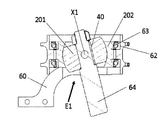
도 2a 내지 도 2c는 본 발명에 따른 커플링의 예를 도시하며, 이 중 도 2a는 정렬되지 않은 커플링의 요소에 대한 축 방향 도면이고, 도 2b는 축선(A3)을 따른 도 2a의 횡단면도이고, 도 2c는 축선(A2)을 따른 도 2a의 횡단면도이며,
도 3a 및 도 3b는 도 2에 따른 커플링의 예를 포함하는 허브 중심 스티어링 기구를 도시하며, 이 중 도 3a는 등각도이고 도 3b는 횡단면도이며,
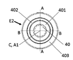
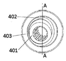
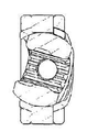
도 4a 내지 도 4f는 본 발명에 따른 커플링의 다른 예를 도시하며, 이 중 도 4a는 도 1의 축선(A1)을 따른 축 방향 도면이고, 도 4b는 도 4a의 평면(A-A)을 따른 횡단면도이고, 도 4c는 도 4a의 평면(B-B)을 따른 횡단면도이고, 도 4d는 정렬되지 않은 커플링의 요소를 도시하는 축 방향 도면이고, 도 4e는 도 4a의 커플링의 축 방향 횡단면도이고, 도 4f는 도 4d의 평면(A-A)을 따른 횡단면도이며,
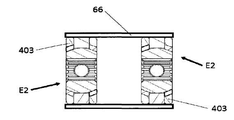
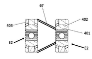
도 5a 및 도 5b는 서로 연결된 도 4의 커플링 쌍의 횡단면도이며,
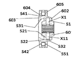
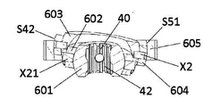
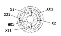
도 6a 내지 도 6f는 본 발명에 따른 커플링의 다른 예를 도시하며, 이 중 도 6a는 도 1의 축선(A1)을 따른 축 방향 도면이고, 도 6b는 도 6a의 평면(A-A)을 따른 횡단면도이고, 도 6c는 도 6a의 평면(B-B)을 따른 횡단면도이고, 도 6d는 측면도이고, 도 6e는 도 6d의 평면(C-C)을 따른 횡단면도이고, 도 6f는 도 6d의 평면(D-D)을 따른 커플링의 측 횡단면도이며,
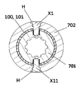
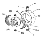
도 7a 내지 도 7c는 본 발명에 따른 커플링의 하나의 대표적인 부재 상의 베어링을 도시하며, 이 중 도 7a는 커플링의 등각도이고, 도 7b는 축 방향의 횡단면도이고, 도 7c는 분해도이며,
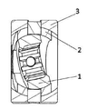
도 8은 본 발명에 따른 커플링의 요소의 상대 회전을 제한하기 위한 수단을 도시하며,
도 9는 본 발명에 따른 커플링에 적용될 수 있는 수정예의 횡단면도이며,
도 10은 베어링 내부의 본 발명에 따른 대표적인 커플링의 횡단면도이며,
도 11a 및 도 11b는 이전의 예에서 설명된 커플링을 조립하는 방법을 예시한다.Some examples of the present invention are described below with reference to the accompanying drawings,
1 illustrates a reference frame for operation of a coupling according to an embodiment of the present invention,
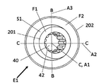
2A to 2C show an example of a coupling according to the present invention, wherein FIG. 2A is an axial view of an element of an unaligned coupling, FIG. 2B is a cross-sectional view of FIG. 2A along an axis A3, Fig. 2C is a cross-sectional view of Fig. 2A along the axis A2,
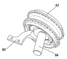
Figures 3a and 3b illustrate a hub center steering mechanism including an example of a coupling according to Figure 2, wherein Figure 3a is an isometric view and Figure 3b is a cross-
4A to 4F show another example of the coupling according to the present invention, wherein FIG. 4A is an axial view along the axis A1 of FIG. 1, and FIG. 4B is a view along the plane AA of FIG. 4C is a cross-sectional view along the plane BB of FIG. 4A, FIG. 4D is an axial view showing the elements of the unaligned coupling, FIG. 4E is an axial cross-sectional view of the coupling of FIG. Figure 4f is a cross-sectional view along plane AA of Figure 4d,
5A and 5B are cross-sectional views of the coupling pair of FIG. 4 connected to each other,
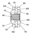
6A to 6F show another example of the coupling according to the present invention, wherein FIG. 6A is an axial view along the axis A1 of FIG. 1, and FIG. 6B is a view along the plane AA of FIG. 6D is a cross-sectional view along the plane BB of Fig. 6A, Fig. 6D is a side view, Fig. 6E is a cross-sectional view along the plane CC of Fig. 6D, Fig. 3 is a side cross-
Figures 7a to 7c show bearings on one representative element of a coupling according to the invention, wherein Figure 7a is an isometric view of the coupling, Figure 7b is a transverse cross-sectional view, Figure 7c is an exploded view,
Figure 8 shows the means for restricting the relative rotation of the elements of the coupling according to the invention,
9 is a cross-sectional view of a modification that may be applied to a coupling according to the present invention,
Figure 10 is a cross-sectional view of an exemplary coupling according to the present invention within a bearing,
11A and 11B illustrate a method of assembling the coupling described in the previous example.
도면의 본 발명의 예가 도 1에 도시된 바와 같은 기준 프레임과 관련하여 설명된다.An example of the invention of the drawing is described with reference to a reference frame as shown in Fig.
기준 프레임은 축 방향을 규정하는 제1 축선(A1)을 가진다. 제2 축선(A2)은 제1 축선(A1)에 수직하다. 제1 및 제2 축선의 교차점에 있는 것은 커플링의 동심 부재의 동심 구형 표면의 중심점(C)이다. 제1 및 제2 축선 및 중심점은 제1 평면(P1)에 놓이며 제1 축선 및 중심점은 제1 평면에 수직한 제2 평면(P2)에 놓인다. 중심점(C)을 통과하는 제3 평면(P3)은 다른 평면과 수직하다. 축선(A1 및 A2)과 수직한 제3 축선(A3)은 제3 평면에 놓이고 중심점(C)을 통과한다.The reference frame has a first axis Al defining an axial direction. The second axis A2 is perpendicular to the first axis A1. What is at the intersection of the first and second axes is the center point C of the concentric spherical surface of the concentric member of the coupling. The first and second axes and the center point are located in the first plane (P1), the first axis and the center point are in the second plane (P2) perpendicular to the first plane. The third plane P3 passing through the center point C is perpendicular to the other plane. The third axis A3, which is perpendicular to the axes A1 and A2, lies on the third plane and passes through the center point C.
제1 축선(A1)은 예를 들어, 구동축과 피동축이 커플링에 연결되는 비틀림 축선이며 제2 축선(A2) 및 제3 축선(A3)은 커플링의 부재의 상대 회전의 축선이다.The first axis A1 is, for example, a torsion axis in which the drive shaft and the driven shaft are connected to the coupling, and the second axis A2 and the third axis A3 are axes of relative rotation of members of the coupling.
추가의 예에서, 커플링은 중심점(C)에 중심 맞춰지는 몇몇 부재와 부재가 정렬될 때 제1 축선을 따라 C로부터 오프셋된 다른 중심점(C2)에 중심 맞춰지는 몇몇 부재를 가진다. C로부터 C2로의 오프셋은 약간, 예를 들어, 밀리미터의 몇 분의 1일 수 있다. 축선(A2 및 A3)에 평행한 다른 축선(A21 및 A31)은 각각 중심점(C2)을 통과한다.In a further example, the coupling has some member centered on the center point C and some member centered on the other center point C2 offset from C along the first axis when the member is aligned. The offset from C to C2 may be somewhat, for example a fraction of a millimeter. The other axes A21 and A31 parallel to the axes A2 and A3 pass through the center point C2, respectively.
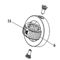
도 2에서, 커플링은 제1 축선(A1) 주위에 내부 환형 부재(201)를 포함한다. 내부 부재(201)는 중심점(C) 주위에 구형 부분을 포함하며 제1 축선 상의 중심점(C)에 중심 맞춰지는 볼록한 구형인 외부 주변부 표면(S1)을 가진다. 내부 부재(201)는 본 예에서 대응하는 스플라인 축을 결합시키기 위한 스플라인(42)을 가지는 중심의 원통형 보어(40)를 가진다.In Figure 2, the coupling includes an inner
외부 환형 부재(202)는 내부 부재(201)의 외부 표면(S1)과 상보적인 볼록한 구형인 내부 주변부 표면(S21)을 가진다. 오목 구형 표면(S21)은 내부 링의 구형 표면으로서 축선 상의 동일한 중심점(C)에 중심 맞춰진다. 본 예에서 외부 링의 내부 구형 표면(S21) 및 내부 부재(201)의 외부 구형 표면(S1)은 인접한 플레인 베어링(plain bearing) 표면이다.The outer
내부 및 외부 환형 부재(201,202)는 중심점(C)을 통과하는 공통 축선, 본 경우에 축선(A3)인 정반대의 축선(X1,X11)을 포함하는 축 배열에 의해 커플링된다. 축선 쌍은 내부 및 외부 링이 축선(A3)을 중심으로 서로에 대해 회전될 수 있도록 강요한다.The inner and outer
각각의 축선(X1,X11)은 외부 환형 부재(202)의 보어(B2)에 고정되고 그 내부에서 자유롭게 회전하는 내부 부재(201)의 보어(B1) 내부로 연장하는 액슬 샤프트(XS)를 포함한다. 그 샤프트는 이들이 내부 링과 외부 링 사이로 반경 방향 하중을 전달하지 않도록 배열된다. 이는 축선의 단부와 반경 방향으로 인접하는 구형 표면 사이에 반경 방향 틈새를 제공하고 액슬 샤프트(XS)와 내부 부재(201) 사이의 보어(B1) 내에서 약간의 반경 방향 운동 자유도를 허용함으로써 수행되며, 이러한 배열은 반경 방향과 축 방향 하중 모두로부터 축선을 격리시킨다.Each of the axes X1 and X11 includes an axle shaft XS which is fixed to the bore B2 of the outer
액슬 샤프트는 간섭 끼워 맞춤에 의해 외부 환형 부재(202)에 고정되거나 그와는 달리 예를 들어 냉간 용접에 의해 고정될 수 있다.The axle shaft may be fixed to the outer
축선은 다른 형태를 취할 수 있다. 액슬 샤프트(XS)는 외부 표면 위로 돌출하지 않고 외부 부재의 보어(B2) 내에 나사산 결합에 의해 외부 부재(202)에 고정되도록 외부 부재(202)의 외부 표면의 리세스에 헤드를 가질 수 있다.The axis can take other forms. The axle shaft XS may have a head at the recess of the outer surface of the
축선은 외부 부재(202) 내부에 축 방향으로 내부 부재(201)를 유지한다. 또한, 내부 및 외부 부재의 구형 표면은 외부 부재 내부에 축 방향으로 내부 부재를 유지하도록 공동 작용한다.The axis holds the
인접한 볼록 및 오목 구형 표면의 중심점(C)은 내부 부재(201)의 축 방향 대향 면(F1 및 F3) 사이에 그리고 외부 부재(202)의 대향 면(F2 및 F4) 사이에 놓인다. 그 결과로, 축 방향 대향 면(F1 및 F3) 사이의 중간에서 내부 볼록 구형 표면의 주변부는 그의 축 방향 대향 면(F2 및 F4)에서 외부 부재(202)의 오목 표면의 주변부보다 더 큰 반경에 있다. 따라서 내부 부재(201)는 제2 축선 및/또는 제1 축선을 중심으로 한 내부 환형 부재(201)의 회전 작동 범위에 걸쳐서 외부 환형 외부 부재(202) 내에 축 방향으로 유지된다.The center point C of the adjacent convex and concave spherical surfaces lies between the axially opposing faces F1 and F3 of the
도 2의 예에서, 내부 부재(201)는 축을 결합시키기 위한 그의 중심의 원통형 보어 내에 스플라인을 가진다. 스플라인(도시 않음)은 다른 축을 결합시키기 위한 최외부 부재(본 경우에 외부 환형 부재(202))의 외부 주변부에 추가로 또는 대안으로 제공될 수 있다. 커플링은 축(들)에 대한 미끄럼을 허용하여 축 방향의 자유도를 제공할 수 있다.In the example of FIG. 2, the
제1 및 제2 환형 부재는 제1 축선(A1) 및 제2 축선(A2)의 교차점에서 중심점(C)에 중심 맞춰지는 각각의 구형 섹션이다.The first and second annular members are respective spherical sections centered at the center point C at the intersection of the first axis A1 and the second axis A2.
도 2에 도시된 바와 같이, 커플링 상의 하중을 공유하는 두 개의 정반대 축선(X1 및 X11)이 있다. 하나는 커플링이 경 하중하에서 작동하도록 설계된다면 생략될 수 있다.As shown in Fig. 2, there are two opposing axes X1 and X11 sharing a load on the coupling. One can be omitted if the coupling is designed to operate under light load.
도 2의 예는 도 3에 도시된 바와 같은 허브 센터 스티어링(Hub Centre Steering)과 같은 정적 용례를 가진다.The example of FIG. 2 has static applications such as Hub Center Steering as shown in FIG.
도 3에서 휠의 스티어링 휠 허브(62)는 본 예에서 서스펜션 아암인 지지 부재(64)에 의해 지지된다. 도 2를 참조하여 설명된 바와 같이 커플링(E1)은 서스펜션 아암(64)을 스티어링 휠 허브(62)에 커플링한다. 아암(64)은 커플링(E1)의 내부 링(201)의 중심 보어(40)에 예를 들어 스프라인에 의해 결합된다. 축선(들)(X1,X11)(단지 X1만이 도시됨)은 외부 환형 부재(202)가 내부 환형 부재(201)와 아암(64)에 대해 하나의 축선(스티어링 축선)을 중심으로 회전하게 한다. 외부 환형 부재(202)는 베어링(63) 상에서 자유롭게 회전하는 휠(62)을 지지한다. 스티어링 아암(60)은 내부 링과 아암(64)에 대해 그를 회전시키도록 외부 환형 부재(202)에 고정된다.In Fig. 3, the
본 예에서 축선(들)(X1,X11)은 상대 회전을 허용하나 휠 허브(62)를 구동시키지 않는 지지대를 제공한다.In this example, the axis (s) X1, X11 provide a support that allows relative rotation but does not drive the
제1 축선에 중심이 맞춰지는 내부 환형 부재(401)를 포함하는 커플링의 추가 예가 도 4에 도시되며, 내부 환형 부재(401)는 축선(A1) 상의 점(C)에 중심 맞춰지는 볼록 구형인 외부 주변부 표면(S1)을 가진다. 내부 환형 부재(401)는 대응하는 스플라인 축을 결합시키기 위한 스플라인을 가지는 중앙 원통형 보어(40)를 가진다.A further example of a coupling comprising an inner
중앙 환형 부재(402)는 내부 부재(402)의 외부 표면(S1)과 상보적인 오목 구형인 내부 주변부 표면(S21)을 가진다. 본 예에서 제2 부재의 내부 구형 표면(S21) 및 내부 부재(401)의 외부 구형 표면(S1)은 인접한 플레인 베어링 표면이다.The central
정반대의 제 1 축선 쌍(X1과 X11)은 내부 부재(401)를 중간 부재(402)에 커플링시키도록 제3 축선(A3) 상의 제1 축선(A1)의 반경 방향으로 연장한다. 제1 및 제2 축선은 내부 부재 및 중간 부재가 제3 축선(A3)을 중심으로 하여 서로에 대해 회전하도록 강요한다. 중간 부재(402)는 볼록 구형인 외부 주변부(S22)를 가진다. 외부 환형 부재(403)는 중간 부재(402)의 외부 표면(S22)과 상보적인 오목 구형인 내부 주변부 표면(S31)을 가진다. 본 예에서 외부 부재(403)의 내부 구형 표면(S31) 및 중간 부재(402)의 외부 구형 표면(S22)은 인접한 플레인 베어링 표면이다.The opposite first axis pairs X1 and X11 extend in the radial direction of the first axis A1 on the third axis A3 so as to couple the
정반대의 제2 축선 쌍(X2와 X21)은 중간 부재(402)를 외부 부재(403)에 커플링시키기 위해서 제3 축선(A3)에 수직한 제2 축선(A2)을 따라서 제1 축선(A1)의 반경 방향으로 연장한다. 축선(X2 및 X21)은 중간 부재(402) 및 외부 부재(403)가 중심 점(C)을 통과하고 제1 축선(A1)에 수직하고 제3 축선(A3)에 수직한 제2 회전 축선(A2)(도 1 참조)을 중심으로 하여 서로에 대해 회전될 수 있도록 강요한다. 제2 축선 쌍은 내부 부재(401)와 중간 부재(402)를 포함하는 부재 쌍과 무관하게 중간 부재(402)와 외부 부재(403)를 포함하는 부재 쌍의 상대 회전을 허용한다.The opposite second pair of axes X2 and X21 are connected to a first axis A1 along a second axis A2 perpendicular to the third axis A3 in order to couple the
도 2를 참조하여 설명한 것과 유사한 방식으로 구형 표면(S1,S21,S22 및 S31)은 축선(A1)의 반경 방향으로 그리고 축선(A1)의 방향으로 하중을 지지한다. 축선은 내부 부재(401), 중간 부재(402) 및 외부 부재(403) 사이로 토크를 전달한다.The spherical surfaces S1, S21, S22 and S31 support the load in the radial direction of the axis A1 and in the direction of the axis A1 in a manner similar to that described with reference to Fig. The axis transmits torque between the
내부 부재(401)는 중간 부재(402) 내에 유지되며 중간 부재(402)는 도 2의 내부 부재(201)가 외부 부재(202) 내에 유지되는 것과 동일한 방식으로 외부 부재(403) 내에 유지된다.The
제1 축 또는 다른 구조적 요소는 제1 환형 부재(401) 내의 중심 보어에 결합될 수 있으며 제2 축 또는 다른 구조적 요소는 외부 부재(403)와 결합될 수 있다. 그러한 목적을 위해 외부 부재(403)는 플랜지(도시 않음)에 고정되거나 그와 통합될 수 있거나, 외부 부재는 구조적 요소에 커플링하기 위한 다른 부재, 예를 들어 외부 스플라인을 포함할 수 있다.The first axis or other structural element can be coupled to the central bore in the first
도 4의 커플링의 하나의 용도는 유니버설 조인트로서의 용도이다. 커플링은 각각 제3 축선(A3)과 제2 축선(A3)을 중심으로 한 중간 부재(402)와 외부 부재(403)의 상대 회전 덕분에 축의 각도 오정렬을 허용한다.One application of the coupling of Figure 4 is for use as a universal joint. The coupling permits angular misalignment of the axes due to the relative rotation of the
내부 부재(401)와 중간 부재(402) 모두는 중심점(C)을 중심으로 구형 부분을 포함한다.Both the
도 5a 및 도 5b에서 도 4에 예시된 종류의 두 개의 커플링을 포함하는 커플링 배열이 도시된다.In Figs. 5A and 5B a coupling arrangement is shown comprising two couplings of the kind illustrated in Fig.
도 5a에서 도 4의 두 개의 커플링(E2)은 커넥팅 구조물(66)에 의해 함께 연결된다. 구조물은 두 개의 커플링을 단단히 연결한다. 연결 구조물(66)은 외부 부재(403)를 커플링하는 튜브이다. 다른 예에서, 튜브 대신에 하나의 커플링의 외부 부재(403)는 연결 구조물(67)에 의해서 예를 들어, 도 5b에 도시된 바와 같은 다른 커플링의 제1 부재(401)에 연결된다. In Fig. 5A, the two couplings E2 of Fig. 4 are connected together by a connecting
도 5a의 커플링 배열은 개별 커플링(E2)의 하나의 축선 쌍이 대응하는 다른 하나의 축선 쌍과 직교하지 않는다면, 이중 카르단 조인트(double Cardan joint)에 가깝다.The coupling arrangement of Figure 5a is close to a double Cardan joint unless one axis pair of individual couplings E2 is orthogonal to the corresponding one of the axis pairs.
도 4의 커플링(E2)을 사용하는 대신에, 도 2의 커플링이 사용되면, 커플링 배열은 두 개의 커플링의 축선이 동일한 방위로 있는 경우에 크랭크 핸들이다. 다른 예에서 하나의 커플링의 축선(들)이 다른 하나의 돌기(들)와 직교한다.Instead of using the coupling E2 of FIG. 4, if the coupling of FIG. 2 is used, the coupling arrangement is a crank handle when the axes of the two couplings are in the same orientation. In another example, the axis (s) of one coupling is orthogonal to the other one (s).
커플링의 하나는 튜브(66) 내에서 축 방향으로 자유롭게 이동할 수 있다.One of the couplings is free to move axially within the
도 6의 커플링은 내부 환형 부재(601), 제1, 제2, 제3 중간 환형 부재(602,603,604) 및 외부 환형 부재(605)를 포함한다.The coupling of Figure 6 includes an inner
제3 중간 부재(604) 및 외부 부재(605)는 부재가 정렬될 때(도 6d 참조) 축선(A1)을 따라 내부 및 중간 부재(601 및 602)에 대해 오프셋되어야 함이 발견되었다. 그 오프셋은 약간일 수 있다. 이는 제2 중간 부재(603)의 내부 구형 표면(S31)의 축 방향으로 제2 중간 부재(603)의 외부 구형 표면(S32)을 오프셋함으로써 달성될 수 있다. 따라서, 도 1의 기준 프레임을 사용하여 내부 및 제1 중간 부재(601 및 602)는 중심점(C)에 중심 맞춰지며 제2 및 제3 중간 부재(603 및 604)는 중심점(C2)에 중심 맞춰진다.It has been found that the third
제1 환형 부재(601)는 제1 축선(A1) 상의 중심점(C)에 중심 맞춰지는 볼록 구형인 외부 주변부 표면(S1)을 가진다. 제1 환형 부재(601)는 본 예에서 대응 스플라인 축을 결합시키기 위한 스플라인(42)을 가지는 중심의 원통형 보어(40)를 가진다.The first
제1 중간 환형 부재(602)는 내부 부재(601)의 외부 표면(S1)과 상보적인 오목 구형인 내부 주변부 표면(S21)을 가진다. 표면(S1 및 S21)은 인접한 플레인 베어링 표면이다.The first intermediate
정반대인 제1 축선 쌍(X1,X11)은 내부 부재(601)와 제1 중간 부재(602)를 커플링하기 위해서 제1 축선(A1)의 반경 방향으로 제3 축선(A3)을 따라서 연장한다.제1 축선 쌍은 내부 및 제1 중간 부재(601 및 602)를 포함하는 부재 쌍이 제1 축선(A1)을 통과하고 그에 수직한 제3 회전 축선(A3)을 중심으로 서로에 대해 회전될 수 있도록 강요한다.The opposite first axis pairs X1 and X11 extend along the third axis A3 in the radial direction of the first axis A1 to couple the
제1 중간 부재(602)는 볼록 구형인 외부 주변부(S22)를 가진다. 제2 중간 환형 부재(603)는 제1 중간 부재(602)의 외부 표면(S22)과 상보적인 오목 구형인 내부 주변부 표면(S31)을 가진다. 이러한 예에서 제2 중간 부재(603)의 내부 구형 표면(S31) 및 제1 중간 부재(602)의 외부 구형 표면(S22)은 인접한 플레인 베어링 표면이다.The first
정반대인 제2 축선 쌍(X2,X21)은 제1 및 제2 중간 부재(602 및 603)를 포함하는 부재 쌍을 커플링하는 제1 축선(A1)의 반경 방향으로 제2 축선(A2)을 따라 연장한다. 제2 축선 쌍은 제1 중간 부재(602) 및 제2 중간 부재(603)가 중심점(C)을 통과하고 제1 축선에 수직하고 제3 축선(A3)에 수직한 제2 회전 축선(A2)을 중심으로 서로에 대해 회전될 수 있도록 강요한다. 제2 축선 쌍은 부재(601 및 602) 쌍과는 무관하게 부재 쌍(602 및 603)의 상대 회전을 허용한다.The opposite second pair of axes X2 and X21 intersect the second axis A2 in the radial direction of the first axis A1 coupling the pair of members including the first and second
제2 중간 부재(603)는 볼록 구형인 외부 주변부(S32)를 가진다. 제3 중간 환형 부재(604)는 제2 중간 부재(603)의 외부 표면(S32)과 상보적인 오목 구형인 내부 주변부 표면(S41)을 가진다. 이런 예에서 제3 중간 환형 부재(604)의 내부 주변부 표면(S41) 및 제2 중간 부재(603)의 외부 구형 표면(S32)은 인접한 플레인 베어링 표면이다.The second
정반대인 제3 축선 쌍(X3,X31)은 제2 및 제3 중간 부재(603 및 604)를 포함하는 부재 쌍을 커플링하는 제1 축선(A1)의 반경 방향으로 제2 축선(A2)을 따라 연장한다. 제3 축선 쌍은 부재(603 및 604)가 중심점(C2)을 통과하고 축선(A2)에 평행한 회전 축선(A21)을 중심으로 서로에 대해 회전될 수 있도록 강요한다. 따라서 이들은 부재 쌍(603과 604)이 축선(A21)을 중심으로 하여 서로에 대해 회전될 수 있도록 강요한다. 제3 축선 쌍은 제1 및 제2 중간 부재와는 무관하게 제2 및 제3 중간 부재의 상대 회전을 허용한다.The third pair of axes X3 and X31 which are opposite to each other have a second axis A2 in the radial direction of the first axis A1 coupling the pair of members including the second and third
제3 중간 부재(605)는 볼록 구형인 외부 주변부(S42)를 가진다.The third
외부 환형 부재(605)는 제3 중간 부재(604)의 외부 표면(S42)과 상보적인 오목 구형인 내부 주변부 표면(S51)을 가진다. 본 예에서 외부 부재(605)의 내부 주변부 표면(S51) 및 제3 중간 부재(604)의 외부 구형 표면(S42)은 인접한 플레인 베어링 표면이다.The outer
정반대인 제4 축선 쌍(X4,X41)은 축선(A3)에 평행하나 중심점(C2)을 통과하는 회전 축선(A31)을 따라 연장한다. 제4 축선 쌍은 부재(604 및 605)가 축선(A21)에 수직하고 회전 축선(A31)을 중심으로 서로에 대해 회전될 수 있도록 강요한다. 따라서 이들은 부재(604 및 605)가 축선(A31)을 중심으로 서로에 대해 회전될 수 있도록 강요한다. 제4 축선 쌍은 부재 쌍(603과 604)과는 무관하게 부재 쌍(603과 604)의 상대 회전을 허용한다.The opposite fourth axis pairs X4 and X41 extend parallel to the axis A3 but along the axis of rotation A31 passing through the center point C2. The fourth pair of axes forces
부재는 도 2를 참조하여 여기서 전술한 것과 동일한 방식으로 커플링에 유지된다.The member is held in the coupling in the same manner as described hereinabove with reference to Fig.
축선(X1 내지 X41)은 도 2의 축선(X1 내지 X11)과 동일하다.The axes X1 to X41 are the same as the axes X1 to X11 in Fig.
도 6a 내지 도 6f에서 내부 및 제1 중간 부재(601,602)는 중심점(C)을 중심으로 원형 부분을 포함하며, 제2 및 제3 중간 부재(603 및 604)도 또한 중심점(C2)을 중심으로 구형 부분을 포함한다. 그러나 제2 중간 부재(603)의 중심 구멍은 중심점(C)을 중심으로 한 구형 부분이며 제1 중간 부재(602)는 이러한 구멍 내부에 수용된다.6A to 6F, the inner and first
도 6의 커플링의 하나의 예시적인 용도는 이중 카르단 조인트로서의 용도이다.One exemplary use of the coupling of Figure 6 is for use as a double cardan joint.
도 2 내지 도 6의 예에서 구형 표면은 모두 인접한 플레인 베어링 표면이다. 롤링 요소 베어링은 인접한 구형 표면들 사이에 제공될 수 있다. 도 7에서, 하나 이상의 케이지(101)에 유지되는 볼 베어링(100)은 커플링 부재의 표면에 제공될 수 있다. 도 7의 예에서, 볼은 내부 부재(701)와 외부 부재(702)의 축선(X1 및 X11)일 수 있는 축선(X)들 사이의, 절반부 구형 부품인 두 개의 볼 바스켓(ball baskets)에 유지된다. 따라서 구형 표면은 반경 방향 및 축 방향 하중을 지지하기 위한 롤링 요소를 가진다. 반경 방향 하중 경로는 가해질 토크 하중과 무관하다. 이러한 접근법은 비틀림 하중과 반경 방향 하중을 모두 지지하기 위해서 홈 내에 볼을 사용하는 것보다 더욱 효과적이다. 도 7에는 두 개의 부재 커플링이 도시되어 있지만, 도 7의 원리는 도 4 또는 도 6에 도시된 바와 같은 하나 이상의 중간 부재를 갖는 베어링으로 확장될 수 있다.In the examples of Figures 2 to 6, the spherical surfaces are all adjacent planar bearing surfaces. Rolling element bearings may be provided between adjacent spherical surfaces. In Fig. 7, a
대안의 또는 추가의 예로서 롤링 요소 베어링(102)은 또한 마찰을 감소시키기 위해서 축선에 장착될 수 있다.As an alternative or as an additional example, the rolling element bearing 102 may also be mounted on the shaft to reduce friction.
내부 부재(701)는 중심점(C) 주위에 구형 부분을 포함한다. 도 7에서 축선(X1 및 X11)은 외부 부재(702) 내부로 삽입되는 헤드(H) 및 외부 부재(702)의 보어 내의 나사와 결합되는 스크류 나사를 가진다.The
예에서 인접한 부재의 구형 표면은 반경 방향 및 축 방향 하중을 지지하도록 협동한다. 커플링이 소정의 축방향 및 반경 방향 하중을 지지할 수 있게 보장하기 위해서 구형 표면은 충분히 중복될 필요가 있다. 따라서 본 발명의 실시예에서 인접한 부재의 상대 회전을 제한하는 수단이 제공될 수 있다. 그러한 제한 수단은 또한 그의 관련 외부 링 내에 각각의 내부 링의 보유를 돕는다. 그러한 제한 수단의 예는 커플링 내부에 스톱을 포함한다. 예를 들어, 도 8에 도시된 바와 같이, 일 예에서 고정 핀(N)은 외부 부재(2)로부터 내부 부재(1)의 슬롯(L)으로 돌출한다. 이는 상대 회전을 제한하는 임의의 다른 적합한 수단이 사용될 수 있다는 것이 이해될 것이다. 몇몇 예에서 커플링은 상대 회전을 제한하는 지지 구조물에 의해 지지된다. 다른 예에서 커플링에 의해 커플링되는 구조적 요소가 상대 회전을 제한한다.In the example, the spherical surfaces of the adjacent members cooperate to support the radial and axial loads. The spherical surface needs to be sufficiently overlapped to ensure that the coupling can support certain axial and radial loads. Thus, in an embodiment of the present invention, means for limiting the relative rotation of adjacent members can be provided. Such a restricting means also assists in retaining each inner ring within its associated outer ring. Examples of such limiting means include a stop within the coupling. For example, as shown in Fig. 8, the fixing pin N projects from the
도 9에 도시된 바와 같이, 상대 회전의 작동 범위를 증가시키기 위해서 인접한 부재(1과 2 또는 2와 3)의 외부 부재(2 또는 3)는 내부 부재(1 또는 2)보다 축 방향으로 더 클 수 있다. 도 9는 도 4에서와 같은 3개의 환형 부재(1,2 및 3)를 도시한다. 이러한 도 9의 원리는 본 발명의 예의 환형 부재 쌍의 어느 것에도 적용될 수 있다.9, the
도 10을 참조하면, 도 2, 도 4 및 도 6의 예들 중 어느 하나는 고정 구조물(112), 예를 들어 벌크 헤드(bulkhead), 바닥 또는 벽에 고정될 수 있는 베어링(110) 내부에 고정될 수 있다. 이는 커플링이, 임의의 두 개의 구조적 요소, 즉 적어도 두 개의 회전 자유도를 갖도록 커플링되어야 하는 고정 구조물(112)의 각각의 측면에 커플링되는 것을 허용한다. 예를 들어 고정 구조물은 차량의 벌크 헤드일 수 있으며 그 커플링은 차량의 스티어링 기구의 섹션을 커플링한다.Referring to Fig. 10, one of the examples of Figs. 2, 4 and 6 includes a fixed
베어링(110)은 도 10의 커플링(E)이 고정 구조물(112) 내부에서 회전될 수 있게 허용한다.The
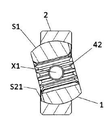
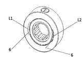
도 11a 및 도 11b는 커플링 조립체를 예시한다. 커플링은 환형 부재 쌍(1과 2)을 포함하며, 외부 부재(2)는 내부 부재(1)의 외부에 있다. 부재(2)는 두 개의 정반대 로딩 슬롯(L1 및 L2)을 가진다. 로딩 슬롯은 외부 부재(2)의 폭을 가로질러 절반만 연장한다(로딩 슬롯은 또한 도 7c에서 볼 수 있다). 슬롯은 슬롯의 정반대 바닥(6)이 외부 표면(S1)(제공된다면 도 7에서와 같은 케이지(101)를 포함함)의 직경만큼 이격될 정도의 크기이다. 각각의 슬롯의 폭은 내부 부재의 폭보다 조금 크거나 같다. 내부 부재(1)는 도 11a에 도시된 바와 같이 슬롯의 내부로 나란히 도입되고 나서 외부 부재(2)와 동일한 평면에서 회전된다. 부재 쌍(1과 2)의 액슬 보어(axle bore)(들)는 조립 공정의 적합한 단계에서 정렬되게 된다.11A and 11B illustrate a coupling assembly. The coupling includes an
이러한 옵션은 각각의 부재가 중실형 부품의 재료로부터 기계 가공될 수 있게 하고 절반부를 함께 결합시킨 결과로써의 고장 위험을 최소화할 수 있다. 설명된 방법은 본 명세서에서 설명된 모든 베어링 표면이 연속적일 수 있게, 즉 함께 볼트 고정 또는 용접된 두 개의 절반부로 조립되는 부재의 결합시 임의의 결합(그리고 그에 따른 약한 구역)을 예방할 수 있게 한다.This option allows each member to be machined from the material of the solid part and minimizes the risk of failure as a result of joining the halves together. The described method makes it possible to prevent any joining (and thus weak areas) when all of the bearing surfaces described herein are continuous, i.e., when assembled together with two halves assembled with bolts or welded together .
도 11에서 부재 쌍(1과 2), 도 2의 부재 쌍(201과 202), 도 4의 부재 쌍(401과 402, 402와 403), 도 6의 부재 쌍(601과 602, 602와 603, 603과 604, 그리고 604와 605), 및 도 7의 부재 쌍(701과 702)는 각각, 각각의 부재를 대표한다.The pair of
위의 예에서, 플레인 베어링 표면을 위해서, 정합하는 볼록 및 오목 구형 표면이 정확히 일치해야 한다. 이는 커플링의 적절한 정밀 제작을 요구한다.In the above example, for the plain bearing surface, the matching convex and concave spherical surfaces must match exactly. This requires proper precise fabrication of the coupling.
라이닝 재료가 구형 베어링 표면들 사이에 주입될 수 있다. 볼록 구형 표면은 정밀하게 기계 가공되어야 한다. 볼록 구형 표면은 또한 캐시드럴링(cathedraling)으로서도 공지된 곡선 표면에 가까운 부분 라이너(piece-wise liner)인 거친 표면을 형성하도록 대략적으로 기계 가공될 수 있으며 라이닝 재료가 정밀하게 정합된 오목 구형 표면을 형성하도록 정밀하게 기계 가공된 볼록 표면과 거친 오목 표면 사이에 주입된다. 볼록 구형 표면은 라이닝이 커플링에 주입되기 이전에 이형제로 코팅된다.A lining material can be injected between the spherical bearing surfaces. The convex spherical surface must be machined precisely. The convex spherical surface can also be roughly machined to form a rough surface, which is also a piece-wise liner close to the known curve surface, also known as cathedraling, and the lining material can have a precisely matched concave spherical surface Lt; RTI ID = 0.0 > machined convex < / RTI > The convex spherical surface is coated with a release agent before the lining is injected into the coupling.
라이닝 재료는 플라스틱일 수 있다. 몇몇 플라스틱의 조성은 그의 조성에 관하여 공급자에게는 상업적으로 민감하기 때문에 대중적으로 공지되지 않았다. 그러나 Delrin®은 사용될 수 있는 하나의 공지된 제품이거나 PTFE 계열의 재료가 사용될 수 있다.The lining material may be plastic. The composition of some plastics has not been publicly known since it is commercially sensitive to suppliers regarding its composition. However, Delrin® may be one known product that can be used or a PTFE-based material.
위에서 도시된 것에 대한 대안의 실시예에서 축과 같은 구조적 요소는 커플링의 내부 부재에 고정되거나 그에 통합될 수 있다. 대안의 실시예에서 축과 같은 구조적 요소는 커플링의 외부 부재에 고정되거나 그에 통합될 수 있다. 구조적 요소는 커플링의 내부 및 외부 부재 모두에 고정되거나 그에 통합될 수 있다.In an alternative embodiment to that shown above, a structural element, such as an axis, may be fixed to or integrated with the inner member of the coupling. In alternate embodiments, structural elements such as shafts may be secured to or integrated with the outer member of the coupling. The structural element may be fixed to or integrated with both the inner and outer members of the coupling.
전술한 예는 커플링을 커플링될 구조적 요소에 연결하는 커플링의 내부 링에 및/또는 최외부 주변부 표면에 스플라인을 가질 수 있다.The above example may have a spline on the inner ring of the coupling connecting the coupling to the structural element to be coupled and / or on the outermost peripheral surface.
대안으로 커플링을 구조적 요소에 연결하는 임의의 다른 적합한 수단이 사용될 수 있다. 예를 들어, 외부 주변부는 이를 대응하는 나사 형성된 구조적 요소에 연결하기 위한 나사산을 가질 수 있다. 유사하게 내부 부재는 축을 연결하기 위해서 나사산이 형성되거나 키를 사용할 수 있는 중심 보어를 가질 수 있다. 내부 부재는 다른 구조적 요소에 연결하기 위한 나사가 형성된 축과 통합될 수 있다. 커플링의 외부 부재는 임의의 적합한 수단에 의해 구조적 요소에 연결될 수 있다.Alternatively, any other suitable means of coupling the coupling to the structural element may be used. For example, the outer periphery may have threads for connecting it to a corresponding threaded structural element. Similarly, the inner member may have a central bore that can be threaded or use a key to connect the shaft. The inner member may be integrated with a threaded shaft for connection to other structural elements. The outer member of the coupling may be connected to the structural element by any suitable means.
전술한 바와 같은 커플링은 임의의 적합한 재료로 만들어질 수 있다. 플레인 베어링 표면을 갖는 예는 금속, 예를 들어 고성능 스틸, 황동, 청동, 알루미늄, 티타늄 등일 수 있거나, 플라스틱, 예를 들어 나이론, 유리 충전된 나이론, 아세탈, ABS, Delrin®일 수 있다.The coupling as described above may be made of any suitable material. Examples with plain bearing surfaces may be metals, such as high performance steel, brass, bronze, aluminum, titanium, etc., or plastics such as nylon, glass filled nylon, acetal, ABS, Delrin®.
도 4의 커플링의 내부 및 외부 환형 부재(401 및 403)는 중간 부재(402)가 단지 다른 두 개의 부재에 대해 이동하는 일부가 되도록 각각의 축 또는 다른 구조적 부재에 연결될 수 있으며, 이는 디자이너에게 이동하는 중간 부재용으로 황동 또는 청동을 그리고 내부 부재(601)와 외부 부재(603)용으로 스틸을 선택하도록 유도할 수 있음에 주목해야 한다. 동일한 사상이 다른 커플링에도 적용될 수 있다.The inner and outer
금속 환형 부재 링은 종래의 윤활유, 예를 들어 그리스에 의해 윤활될 수 있다. 대안으로, 위에서 논의된 바와 같은 플라스틱 라이너와 같은 건식 윤활유 표면이 제공될 수 있다. 재료와 윤활유의 선택은 커플링의 의도된 용도에 의존한다.The metallic annular member ring may be lubricated by conventional lubricants, for example grease. Alternatively, a dry lubricant surface such as a plastic liner as discussed above may be provided. The choice of material and lubricant depends on the intended use of the coupling.
모든 예의 내부 부재는 축을 수용하기 위한 중심 구멍을 갖춘 환형의 구형 부재를 포함한다. 그러나 중심 구멍을 갖지 않고 예를 들어, 축의 플랜지에 볼트 연결될 수 있다.The inner member of all examples includes an annular spherical member with a central hole for receiving the shaft. However, it can be bolted to the flange of the shaft without having a center hole, for example.
도시된 예에서, 최대 소형화를 위해서 구형 부분을 포함하는 부재 쌍의 각각의 부재에는 그 부분이 정렬될 때 공통 평면 내에 평행한 측면을 가진다. 특히:In the illustrated example, for maximum miniaturization, each member of the pair of members, including the spherical portion, has a side parallel to the common plane when that portion is aligned. Especially:
- 도 2의 배열에서 부재 쌍의 각각의 부재는 정렬될 때 공통 평면에 평행한 측면을 가지는 구형 부분을 포함하며;- each member of the pair of members in the arrangement of Figure 2 comprises a spherical portion having a side parallel to the common plane when aligned;
- 도 4의 배열에서 각각의 부재는 정렬될 때 공통 평면에 평행한 측면을 가지는 구형 부분을 포함하며;- each member in the arrangement of Figure 4 comprises a spherical portion having a side parallel to the common plane when aligned;
- 도 6의 배열에서 제1 부재 쌍(601,602)의 각각의 부재는 정렬될 때 공통 평면에 평행한 측면을 갖는 구형 부분을 포함하며 제3 부재 쌍(603,604) 및 제4 부재 쌍(604,605)의 각각의 부재는 정렬될 때 공통 평면에 평행한 측면을 갖는 구형 부분을 포함한다. 하지만, 이는 제2 부재 쌍(602,603)에는 적용되지 않는다.6, each member of the first pair of
Claims (15)
내부 부재와 외부 부재 중 하나 또는 모두를 포함하거나 포함하지 않을 수 있는, 하나 이상의 부재 쌍을 포함하며, 각각의 부재 쌍은 공통 축선(A1)과 그 축선 상에 공통의 제1 중심점(C)을 가지는 제1 부재와 제2 환형 부재이며, 제1 부재는 외부 볼록 구형 주변부(S1)를 가지며, 제2 환형 부재는 제1 환형 부재의 외부 볼록 주변부가 수용되는 내부 구형 오목 주변부(S21)를 가지며, 외부 볼록 주변부와 내부 오목 주변부는 제1 중심점(C)에 대해 동심이고 서로 상보적이며 그들 사이의 비틀림 축선(A1)을 따라 작용하는 축 방향 하중을 전달하도록 서로에 대해 공동-작용하며, 하나 또는 정반대의 축선(X) 쌍은 부재의 하나로부터 부재의 다른 하나로 비틀림 하중을 전달하기 위해서 제1 공통 중심의 반경 방향으로 배치되며, 제1 및 제2 부재는 축선(들)을 중심하여 서로에 대해 회전될 수 있도록 축선(들)에 의해 강요되는 커플링.A coupling having an inner member and an outer annular member,
Wherein each pair of members includes a common axis A1 and a common first central point C on the axis thereof, The first member has an outer convex spherical peripheral portion S1 and the second annular member has an inner spherical concave peripheral portion S21 in which the outer convex peripheral portion of the first annular member is received , The outer convex peripheral portion and the inner concave peripheral portion cooperate with each other to transmit an axial load which is concentric with respect to the first central point C and complementary to each other and which acts along the torsional axis A1 between them, Or opposite pairs of axes X are arranged in the radial direction of the first common center to transmit a torsional load from one of the members to the other of the members and the first and second members are arranged about the axis (S) so as to be rotatable relative to the furnace.
외부 부재 이외에, 상기 부재는 공통 중심(C,C2)을 포함하는 구형 부분을 포함하는 커플링.The method according to claim 1,
In addition to the outer member, the member includes a spherical portion including a common center (C, C2).
커플링의 반경 방향 하중 및 상기 비틀림 축선(A1)을 따라 작용하는 하중을 지지하는 볼록 및 오목 구형 표면(S1,S21)이 인접해 있는 커플링.3. The method according to claim 1 or 2,
Wherein the convex and concave spherical surfaces (S1, S21) supporting the radial load of the coupling and the load acting along said torsion axis (A1) are adjacent.
볼록 및 오목 구형 표면들 사이에 및/또는 축선(X)들 주위에 롤링 요소 베어링(100,102)를 더 포함하는 커플링.The method according to any one of claims 1 to 3,
A coupling comprising rolling element bearings (100, 102) between convex and concave spherical surfaces and / or around axes (X).
부재 쌍의 제2 환형 부재(202,402,403,602,603,604,605)는 부재 쌍의 제1 부재(201,401,402,601,602,603,604)를 커플링 내부에 유지하는 커플링.5. The method according to any one of claims 1 to 4,
The pair of second annular members (202,402,403,602,603,604,605) maintain the first member (201,401,402,601,602,603,604) of the pair of members inside the coupling.
부재 쌍의 제2 환형 부재는 부재 쌍의 제 1 부재가 커플링 내부에 유지되도록 삽입될 수 있는 정반대의 로딩 슬롯 쌍(L1,L2)을 가지는 커플링.6. The method according to any one of claims 1 to 5,
The second annular member of the member pair has a pair of opposite loading slots (L1, L2) that can be inserted such that the first member of the member pair is retained within the coupling.
최내부 부재(401), 중간 부재(402) 및 최외부 부재(403)를 포함하며, 최내부 부재(401)와 중간 부재(402)는 제1 부재 쌍을 포함하고 중간 부재(402)와 최외부 부재(403)는 제2 부재 쌍을 포함하며, 제2 부재 쌍(402,403)을 커플링하는 축선(X2,X21)(들)은 제1 부재 쌍(401,402)을 연결하는 축선(X1,X11)(들)과 수직하며, 제2 부재 쌍은 제1 부재 쌍과 무관하게 서로에 대해 회전될 수 있는 커플링.7. The method according to any one of claims 1 to 6,
The innermost member 401 and the intermediate member 402 include the first member pair and the intermediate member 402 and the outermost member 403. The innermost member 401 includes the innermost member 401, the intermediate member 402, The outer member 403 includes a second pair of members and the axes X2 and X21 coupling the second pair of members 402 and 403 are connected to axes X1 and X11 connecting the first pair of members 401 and 402 (S), and the second pair of members can be rotated relative to each other independently of the first pair of members.
제1 부재(602), 제2 부재(603) 및 제3 중간 부재(603)를 가지며, 내부 부재(601)와 제1 중간 부재(602)는 제1 부재 쌍을 형성하며, 제1 부재(602)와 제2 중간 부재(603)는 제2 부재 쌍이며, 제2 부재(603)와 제3 중간 부재(604)는 제3 부재 쌍이며, 제3 중간 부재(604)와 최외부 부재(605)는 제4 부재 쌍인 커플링.6. The method according to any one of claims 1 to 5,
The first member 602, the second member 603 and the third intermediate member 603, the inner member 601 and the first intermediate member 602 form a first member pair, and the first member 602, 602 and the second intermediate member 603 are the second member pair and the second member 603 and the third intermediate member 604 are the third member pair and the third intermediate member 604 and the outermost member 605) is a fourth member pair.
제3 부재 쌍의 경우에 그들의 축선(X3,X31)을 포함하는 평면은 제1 부재 쌍의 축선(X1,X11)을 포함하는 평면과 수직이고 제2 부재 쌍의 축선(X2,X21)을 포함하는 평면과 일치하는 커플링.9. The method of claim 8,
In the case of the third member pair, the plane including the axes X3 and X31 thereof is perpendicular to the plane including the axes X1 and X11 of the first member pair and includes the axes X2 and X21 of the second member pair Coupling that matches the plane.
제2 중간 부재(603)의 볼록 외부 표면은 부재가 정렬될 때 공통 축선(A1)의 방향으로 제1 공통 중심(C)으로부터 오프셋된 제2 공통 중심(C2)을 중심으로 볼록 구형인 외부 주변부(S32)를 가지는 커플링.10. The method according to claim 8 or 9,
The convex outer surface of the second intermediate member 603 has a convex spherical outer periphery 602 about a second common center C2 offset from the first common center C in the direction of the common axis A1 when the members are aligned. (S32).
제3 중간 부재(603)는 제2 공통 중심점에 중심 맞춰지는 그의 외부 볼록 주변부(S32) 및 제1 공통 중심점(C)에 중심 맞춰지는 그의 내부 오목 주변부를 가지는 커플링.11. The method according to any one of claims 8 to 10,
The third intermediate member (603) has its outer convex peripheral portion (S32) centered on the second common center point and its inner concave peripheral portion centered on the first common center point (C).
제4 부재 쌍을 연결하는 축선(X4,X41)(들)은 제3 부재 쌍을 연결하는 축선(X3,X31)(들)에 평행하며 제4 부재 쌍(604,605)은 제1, 제2 및 제3 부재 쌍과 무관하게 제2 공통 중심점을 중심으로 일 방향으로 서로에 대해 회전될 수 있는 커플링.The method according to any one of claims 8 to 11,
Axes X4 and X41 (s) connecting the fourth member pair are parallel to the axis X3 and X31 (s) connecting the third member pair and the fourth member pair 604 and 605 are parallel to the first, The coupling being rotatable relative to each other in one direction about a second common center point, independent of the third pair of members.
연결 구조물은 각각의 커플링의 최외부 부재들 또는 하나의 커플링의 최외부 부재를 다른 커플링의 최내부 부재에 연결하며, 또한 커플링들 중 하나가 연결 구조물에 대해 축 방향으로 자유롭게 이동하는 선택적인 대책이 이루어지거나 이루어지지 않는 커플링 장치.A coupling device comprising two couplings according to any one of claims 1 to 12 connected by connection structures (66, 67)
The connecting structure connects the outermost members of each coupling or the outermost member of one coupling to the innermost member of the other coupling and also one of the couplings moves freely in the axial direction relative to the coupling structure A coupling device with or without an optional countermeasure.
축선(들)은 부재 쌍의 각각의 부재 사이로 반경 방향 및 축 방향 하중을 전달하지 않는 커플링 또는 커플링 장치.14. The method according to any one of claims 1 to 13,
The axis (s) do not transmit radial and axial loads between each member of the pair of members.
최내부 부재와 최외부 부재 중 하나는 비틀림 축선을 중심으로 한 회전에 대해 고정되는 커플링.
The method according to any one of claims 1 to 14,
Wherein one of the innermost member and the outermost member is secured against rotation about a torsional axis.
Applications Claiming Priority (3)
| Application Number | Priority Date | Filing Date | Title |
|---|---|---|---|
| GB1322097.5A GB2521209A (en) | 2013-12-13 | 2013-12-13 | Coupling |
| GB1322097.5 | 2013-12-13 | ||
| PCT/GB2014/053680 WO2015087081A2 (en) | 2013-12-13 | 2014-12-12 | Coupling |
Publications (1)
| Publication Number | Publication Date |
|---|---|
| KR20160097237A true KR20160097237A (en) | 2016-08-17 |
Family
ID=50030906
Family Applications (1)
| Application Number | Title | Priority Date | Filing Date |
|---|---|---|---|
| KR1020167017102A KR20160097237A (en) | 2013-12-13 | 2014-12-12 | Coupling |
Country Status (8)
| Country | Link |
|---|---|
| EP (1) | EP3080470A2 (en) |
| JP (1) | JP6618909B2 (en) |
| KR (1) | KR20160097237A (en) |
| CN (1) | CN105899830B (en) |
| CA (1) | CA2932041A1 (en) |
| GB (2) | GB2521209A (en) |
| MX (1) | MX2016007458A (en) |
| WO (1) | WO2015087081A2 (en) |
Cited By (1)
| Publication number | Priority date | Publication date | Assignee | Title |
|---|---|---|---|---|
| KR102510713B1 (en) * | 2021-09-13 | 2023-03-16 | (주)중앙카프링 | Coupling with tapered torque limiter |
Families Citing this family (11)
| Publication number | Priority date | Publication date | Assignee | Title |
|---|---|---|---|---|
| GB201510137D0 (en) * | 2015-06-11 | 2015-07-22 | Punk Couplings Ltd | Spragg and ratchet couplings |
| GB201518768D0 (en) * | 2015-10-22 | 2015-12-09 | Punk Couplings Ltd | Coupling and method of assembling a coupling |
| WO2016198867A1 (en) | 2015-06-11 | 2016-12-15 | Punk Couplings Limited | Coupling assembly and application to driven coupling, robotic arm and dual drive |
| GB2556235B (en) | 2015-06-11 | 2019-08-21 | Punk Couplings Ltd | Coupling seal |
| DE102016201775A1 (en) * | 2016-02-05 | 2017-08-10 | Schaeffler Technologies AG & Co. KG | Roller for a pod joint |
| GB201610329D0 (en) | 2016-06-14 | 2016-07-27 | Punk Couplings Ltd | Lead screw nut |
| CN107499834B (en) * | 2017-08-24 | 2019-06-25 | 武汉华星光电技术有限公司 | Composite drive shafts and substrate transfer apparatus |
| FI128065B (en) * | 2018-01-23 | 2019-08-30 | Konecranes Global Oy | Shaft coupling |
| JP7090437B2 (en) * | 2018-03-16 | 2022-06-24 | 清水建設株式会社 | Spherical joint and damping device using this |
| GB2594492A (en) * | 2020-04-30 | 2021-11-03 | Punk Couplings Ltd | Damped coupling |
| CN114502854A (en) * | 2019-10-09 | 2022-05-13 | 朋克联轴器有限公司 | Coupling device |
Family Cites Families (12)
| Publication number | Priority date | Publication date | Assignee | Title |
|---|---|---|---|---|
| US1494465A (en) * | 1921-10-24 | 1924-05-20 | Alfred W Dunn | Universal joint |
| JPS5821023A (en) * | 1981-07-31 | 1983-02-07 | Tokai T R W Kk | Universal joint |
| US5425676A (en) * | 1989-06-28 | 1995-06-20 | Cornay; Paul J. | Universal joint having centering device |
| US5265965A (en) * | 1992-09-02 | 1993-11-30 | Rexnord Corporation | Composite ball and socket bearing with convex outer surface |
| CN1036943C (en) * | 1992-12-26 | 1998-01-07 | 周安朝 | coupling |
| JP2001254724A (en) * | 2000-03-13 | 2001-09-21 | Nippon Thompson Co Ltd | Rolling spherical bearing |
| JP3747186B2 (en) * | 2002-05-15 | 2006-02-22 | 株式会社神戸製鋼所 | Cutter equipment |
| CN2921433Y (en) * | 2006-07-14 | 2007-07-11 | 陈尚勇 | Spherical roller coupling |
| JP2008215557A (en) * | 2007-03-06 | 2008-09-18 | Ntn Corp | Constant velocity universal joint |
| JP2009138803A (en) * | 2007-12-04 | 2009-06-25 | Hiihaisuto Seiko Kk | Spherical bearing and spherical pill retainer |
| JP4369973B2 (en) * | 2007-12-27 | 2009-11-25 | 株式会社日本製鋼所 | Cutter device |
| US9261136B2 (en) * | 2010-11-05 | 2016-02-16 | Koninklijke Philips N.V. | Hydrodynamic tumble disc bearing system |
-
2013
- 2013-12-13 GB GB1322097.5A patent/GB2521209A/en not_active Withdrawn
-
2014
- 2014-12-12 KR KR1020167017102A patent/KR20160097237A/en not_active Application Discontinuation
- 2014-12-12 EP EP14812805.1A patent/EP3080470A2/en not_active Withdrawn
- 2014-12-12 CN CN201480068382.XA patent/CN105899830B/en not_active Expired - Fee Related
- 2014-12-12 WO PCT/GB2014/053680 patent/WO2015087081A2/en active Application Filing
- 2014-12-12 GB GB1422090.9A patent/GB2522768B/en active Active
- 2014-12-12 MX MX2016007458A patent/MX2016007458A/en unknown
- 2014-12-12 JP JP2016539071A patent/JP6618909B2/en not_active Expired - Fee Related
- 2014-12-12 CA CA2932041A patent/CA2932041A1/en not_active Abandoned
Cited By (1)
| Publication number | Priority date | Publication date | Assignee | Title |
|---|---|---|---|---|
| KR102510713B1 (en) * | 2021-09-13 | 2023-03-16 | (주)중앙카프링 | Coupling with tapered torque limiter |
Also Published As
| Publication number | Publication date |
|---|---|
| MX2016007458A (en) | 2017-03-06 |
| CA2932041A1 (en) | 2015-06-18 |
| CN105899830B (en) | 2019-08-02 |
| GB2522768B (en) | 2016-09-14 |
| CN105899830A (en) | 2016-08-24 |
| WO2015087081A3 (en) | 2015-09-17 |
| GB2522768A (en) | 2015-08-05 |
| EP3080470A2 (en) | 2016-10-19 |
| JP6618909B2 (en) | 2019-12-11 |
| JP2016540175A (en) | 2016-12-22 |
| GB2521209A (en) | 2015-06-17 |
| GB201322097D0 (en) | 2014-01-29 |
| WO2015087081A2 (en) | 2015-06-18 |
Similar Documents
| Publication | Publication Date | Title |
|---|---|---|
| KR20160097237A (en) | Coupling | |
| US9759265B2 (en) | Centering mechanism for double cardan joints | |
| KR20160097236A (en) | Coupling | |
| US20060217208A1 (en) | Propshaft with constant velocity joint attachment | |
| US10443660B2 (en) | Articulating torsional coupling | |
| US8449399B2 (en) | Joint assembly with centering flange | |
| US20160298695A1 (en) | Coupling | |
| US20140148258A2 (en) | Sliding ball type constant velocity joint for vehicle | |
| JP2001254754A (en) | Constant velocity stroke joint | |
| US6976922B2 (en) | Precision thrust bearing joint | |
| US20190093710A1 (en) | Coupling | |
| US9784327B2 (en) | Centering mechanism for double cardan joints | |
| US5348512A (en) | Friction reduced constant velocity universal joint | |
| JP2008256180A (en) | Fixed type constant velocity universal joint and its assembling method | |
| JP6050043B2 (en) | Constant velocity universal joint | |
| US8257187B2 (en) | Constant velocity joints | |
| JP2007078081A (en) | Sliding type constant velocity universal joint and its manufacturing method | |
| WO2007049512A1 (en) | Compound constant velocity universal joint | |
| US7097565B2 (en) | Fixed-center articulating constant velocity joint | |
| JP2007078023A (en) | Fixed type constant velocity universal joint and its manufacturing method |
Legal Events
| Date | Code | Title | Description |
|---|---|---|---|
| E902 | Notification of reason for refusal | ||
| E601 | Decision to refuse application |