KR20160092939A - Sequential combustor arrangement with a mixer - Google Patents
Sequential combustor arrangement with a mixer Download PDFInfo
- Publication number
- KR20160092939A KR20160092939A KR1020160009896A KR20160009896A KR20160092939A KR 20160092939 A KR20160092939 A KR 20160092939A KR 1020160009896 A KR1020160009896 A KR 1020160009896A KR 20160009896 A KR20160009896 A KR 20160009896A KR 20160092939 A KR20160092939 A KR 20160092939A
- Authority
- KR
- South Korea
- Prior art keywords
- mixer
- damper
- neck
- wall
- combustion chamber
- Prior art date
Links
Images


Classifications
-
- F—MECHANICAL ENGINEERING; LIGHTING; HEATING; WEAPONS; BLASTING
- F23—COMBUSTION APPARATUS; COMBUSTION PROCESSES
- F23R—GENERATING COMBUSTION PRODUCTS OF HIGH PRESSURE OR HIGH VELOCITY, e.g. GAS-TURBINE COMBUSTION CHAMBERS
- F23R3/00—Continuous combustion chambers using liquid or gaseous fuel
- F23R3/28—Continuous combustion chambers using liquid or gaseous fuel characterised by the fuel supply
- F23R3/34—Feeding into different combustion zones
- F23R3/346—Feeding into different combustion zones for staged combustion
-
- F—MECHANICAL ENGINEERING; LIGHTING; HEATING; WEAPONS; BLASTING
- F23—COMBUSTION APPARATUS; COMBUSTION PROCESSES
- F23R—GENERATING COMBUSTION PRODUCTS OF HIGH PRESSURE OR HIGH VELOCITY, e.g. GAS-TURBINE COMBUSTION CHAMBERS
- F23R3/00—Continuous combustion chambers using liquid or gaseous fuel
- F23R3/02—Continuous combustion chambers using liquid or gaseous fuel characterised by the air-flow or gas-flow configuration
-
- F—MECHANICAL ENGINEERING; LIGHTING; HEATING; WEAPONS; BLASTING
- F23—COMBUSTION APPARATUS; COMBUSTION PROCESSES
- F23R—GENERATING COMBUSTION PRODUCTS OF HIGH PRESSURE OR HIGH VELOCITY, e.g. GAS-TURBINE COMBUSTION CHAMBERS
- F23R3/00—Continuous combustion chambers using liquid or gaseous fuel
- F23R3/28—Continuous combustion chambers using liquid or gaseous fuel characterised by the fuel supply
-
- F—MECHANICAL ENGINEERING; LIGHTING; HEATING; WEAPONS; BLASTING
- F02—COMBUSTION ENGINES; HOT-GAS OR COMBUSTION-PRODUCT ENGINE PLANTS
- F02C—GAS-TURBINE PLANTS; AIR INTAKES FOR JET-PROPULSION PLANTS; CONTROLLING FUEL SUPPLY IN AIR-BREATHING JET-PROPULSION PLANTS
- F02C3/00—Gas-turbine plants characterised by the use of combustion products as the working fluid
- F02C3/20—Gas-turbine plants characterised by the use of combustion products as the working fluid using a special fuel, oxidant, or dilution fluid to generate the combustion products
- F02C3/30—Adding water, steam or other fluids for influencing combustion, e.g. to obtain cleaner exhaust gases
-
- F—MECHANICAL ENGINEERING; LIGHTING; HEATING; WEAPONS; BLASTING
- F23—COMBUSTION APPARATUS; COMBUSTION PROCESSES
- F23M—CASINGS, LININGS, WALLS OR DOORS SPECIALLY ADAPTED FOR COMBUSTION CHAMBERS, e.g. FIREBRIDGES; DEVICES FOR DEFLECTING AIR, FLAMES OR COMBUSTION PRODUCTS IN COMBUSTION CHAMBERS; SAFETY ARRANGEMENTS SPECIALLY ADAPTED FOR COMBUSTION APPARATUS; DETAILS OF COMBUSTION CHAMBERS, NOT OTHERWISE PROVIDED FOR
- F23M20/00—Details of combustion chambers, not otherwise provided for, e.g. means for storing heat from flames
- F23M20/005—Noise absorbing means
-
- F—MECHANICAL ENGINEERING; LIGHTING; HEATING; WEAPONS; BLASTING
- F23—COMBUSTION APPARATUS; COMBUSTION PROCESSES
- F23R—GENERATING COMBUSTION PRODUCTS OF HIGH PRESSURE OR HIGH VELOCITY, e.g. GAS-TURBINE COMBUSTION CHAMBERS
- F23R3/00—Continuous combustion chambers using liquid or gaseous fuel
- F23R3/02—Continuous combustion chambers using liquid or gaseous fuel characterised by the air-flow or gas-flow configuration
- F23R3/04—Air inlet arrangements
- F23R3/06—Arrangement of apertures along the flame tube
-
- F—MECHANICAL ENGINEERING; LIGHTING; HEATING; WEAPONS; BLASTING
- F23—COMBUSTION APPARATUS; COMBUSTION PROCESSES
- F23R—GENERATING COMBUSTION PRODUCTS OF HIGH PRESSURE OR HIGH VELOCITY, e.g. GAS-TURBINE COMBUSTION CHAMBERS
- F23R3/00—Continuous combustion chambers using liquid or gaseous fuel
- F23R3/02—Continuous combustion chambers using liquid or gaseous fuel characterised by the air-flow or gas-flow configuration
- F23R3/16—Continuous combustion chambers using liquid or gaseous fuel characterised by the air-flow or gas-flow configuration with devices inside the flame tube or the combustion chamber to influence the air or gas flow
-
- F—MECHANICAL ENGINEERING; LIGHTING; HEATING; WEAPONS; BLASTING
- F23—COMBUSTION APPARATUS; COMBUSTION PROCESSES
- F23R—GENERATING COMBUSTION PRODUCTS OF HIGH PRESSURE OR HIGH VELOCITY, e.g. GAS-TURBINE COMBUSTION CHAMBERS
- F23R3/00—Continuous combustion chambers using liquid or gaseous fuel
- F23R3/02—Continuous combustion chambers using liquid or gaseous fuel characterised by the air-flow or gas-flow configuration
- F23R3/26—Controlling the air flow
-
- F—MECHANICAL ENGINEERING; LIGHTING; HEATING; WEAPONS; BLASTING
- F23—COMBUSTION APPARATUS; COMBUSTION PROCESSES
- F23R—GENERATING COMBUSTION PRODUCTS OF HIGH PRESSURE OR HIGH VELOCITY, e.g. GAS-TURBINE COMBUSTION CHAMBERS
- F23R3/00—Continuous combustion chambers using liquid or gaseous fuel
- F23R3/42—Continuous combustion chambers using liquid or gaseous fuel characterised by the arrangement or form of the flame tubes or combustion chambers
-
- F—MECHANICAL ENGINEERING; LIGHTING; HEATING; WEAPONS; BLASTING
- F05—INDEXING SCHEMES RELATING TO ENGINES OR PUMPS IN VARIOUS SUBCLASSES OF CLASSES F01-F04
- F05D—INDEXING SCHEME FOR ASPECTS RELATING TO NON-POSITIVE-DISPLACEMENT MACHINES OR ENGINES, GAS-TURBINES OR JET-PROPULSION PLANTS
- F05D2240/00—Components
- F05D2240/35—Combustors or associated equipment
-
- F—MECHANICAL ENGINEERING; LIGHTING; HEATING; WEAPONS; BLASTING
- F05—INDEXING SCHEMES RELATING TO ENGINES OR PUMPS IN VARIOUS SUBCLASSES OF CLASSES F01-F04
- F05D—INDEXING SCHEME FOR ASPECTS RELATING TO NON-POSITIVE-DISPLACEMENT MACHINES OR ENGINES, GAS-TURBINES OR JET-PROPULSION PLANTS
- F05D2270/00—Control
- F05D2270/01—Purpose of the control system
- F05D2270/14—Purpose of the control system to control thermoacoustic behaviour in the combustion chambers
-
- F—MECHANICAL ENGINEERING; LIGHTING; HEATING; WEAPONS; BLASTING
- F23—COMBUSTION APPARATUS; COMBUSTION PROCESSES
- F23R—GENERATING COMBUSTION PRODUCTS OF HIGH PRESSURE OR HIGH VELOCITY, e.g. GAS-TURBINE COMBUSTION CHAMBERS
- F23R2900/00—Special features of, or arrangements for continuous combustion chambers; Combustion processes therefor
- F23R2900/00014—Reducing thermo-acoustic vibrations by passive means, e.g. by Helmholtz resonators
-
- F—MECHANICAL ENGINEERING; LIGHTING; HEATING; WEAPONS; BLASTING
- F23—COMBUSTION APPARATUS; COMBUSTION PROCESSES
- F23R—GENERATING COMBUSTION PRODUCTS OF HIGH PRESSURE OR HIGH VELOCITY, e.g. GAS-TURBINE COMBUSTION CHAMBERS
- F23R2900/00—Special features of, or arrangements for continuous combustion chambers; Combustion processes therefor
- F23R2900/03043—Convection cooled combustion chamber walls with means for guiding the cooling air flow
-
- F—MECHANICAL ENGINEERING; LIGHTING; HEATING; WEAPONS; BLASTING
- F23—COMBUSTION APPARATUS; COMBUSTION PROCESSES
- F23R—GENERATING COMBUSTION PRODUCTS OF HIGH PRESSURE OR HIGH VELOCITY, e.g. GAS-TURBINE COMBUSTION CHAMBERS
- F23R2900/00—Special features of, or arrangements for continuous combustion chambers; Combustion processes therefor
- F23R2900/03045—Convection cooled combustion chamber walls provided with turbolators or means for creating turbulences to increase cooling
-
- F—MECHANICAL ENGINEERING; LIGHTING; HEATING; WEAPONS; BLASTING
- F23—COMBUSTION APPARATUS; COMBUSTION PROCESSES
- F23R—GENERATING COMBUSTION PRODUCTS OF HIGH PRESSURE OR HIGH VELOCITY, e.g. GAS-TURBINE COMBUSTION CHAMBERS
- F23R2900/00—Special features of, or arrangements for continuous combustion chambers; Combustion processes therefor
- F23R2900/03341—Sequential combustion chambers or burners
Abstract
Description
본 발명은 연소기 설비 내로 희석 가스를 혼합하고 맥동을 감쇠시키기 위한 가스 터빈을 위한 순차식 연소기 설비에 관한 것이다. 본 발명은 추가적으로 연소기 설비 내로 희석 가스를 혼합하는 것에 의해 가스 터빈을 작동시키기 위한 방법에 관한 것이다.The present invention relates to a sequential combustor arrangement for a gas turbine to mix diluent gases into a combustor plant and attenuate pulsation. The present invention further relates to a method for operating a gas turbine by mixing a diluent gas into a combustor facility.
풍력 또는 태양광같은 불안정한 재생 가능한 자원에 의한 증가된 전기 발전으로 인하여, 기존의 가스 터빈 기반 발전 플랜트들은 전력 수요의 균형을 유지하고 그리드를 안정화하도록 점점 더 사용된다. 그러므로, 개선된 작업 유연성이 요구된다. 이러한 것은 가스 터빈들이 때때로 기본 부하 디자인 지점보다 낮은 부하, 즉 보다 낮은 연소기 유입 및 연소 온도에서 작동되는 것을 암시한다. Due to increased electrical generation by unstable renewable resources such as wind or solar, conventional gas turbine based power plants are increasingly used to balance power demand and stabilize the grid. Therefore, improved working flexibility is required. This implies that gas turbines are sometimes operated at lower loads than the basic load design point, i.e., at lower combustor inlet and combustion temperatures.
동시에, 배기 가스 제한값 및 전체적인 배기 가스 허용치는 더욱 엄격하게 되어서, 낮은 배기 가스값에서 작동하고, 또한 누적 배기 가스 제한들에 대해 의지하는 것으로서, 부분 부하 작동 및 과도기 동안 배기 가스를 낮게 유지하는 것이 요구된다. At the same time, the exhaust gas limit value and the overall exhaust gas allowance become more stringent, so that it operates at low exhaust gas values and is also dependent on cumulative exhaust gas restrictions, requiring partial load operation and keeping the exhaust gas low during the transient do.
종래의 연소 시스템들의 상태는 예를 들어 상이한 버너, 연료 스테이지 또는 연소기들 중에서 압축기 유입 질량 유동을 조절하는 것에 의해 또는 연료 분할을 제어하는 것에 의해 작업 조건에서 특정의 가변 능력에 대처하도록 디자인된다. 그러나, 이러한 것은 새로운 요구조건에 부합하는데 충분하지 않다. The state of conventional combustion systems is designed to cope with certain variable capabilities in operating conditions, for example, by regulating the compressor inlet mass flow among different burners, fuel stages or combustors, or by controlling the fuel split. However, this is not enough to meet the new requirements.
배기 가스 및 작업 유연성을 더욱 감소시키도록, 순차식 연소가 DE 103 12 971 A1에 제안되었다. 작업 조건에 의존하여, 특히 제1 연소실의 고온 가스 온도에 의존하여, 고온 가스가 제2 버너(소위 순차식 버너)에 들어가기 전에 고온 가스를 냉각하는 것이 필요하다. 이러한 냉각은 연료 주입 및 제2 버너에 있는 제1 연소기의 고온 연도 가스와 주입된 연료의 예혼합을 허용하는 것이 유익할 수 있다. To further reduce emissions and work flexibility, sequential combustion is proposed in
종래의 냉각 방법은 주 고온 가스 유동에서의 높은 압력 강하로 이어지는 열교환기 구조를 요구하거나 또는 측벽들로부터 냉각 매체의 주입을 제안한다. 측벽들로부터의 냉각 매체의 주입을 위하여, 이러한 연소기 설비로 작동되는 가스 터빈의 효율에 유해하고 연소 안정성에서 부정적인 영향 및 맥동을 가질 수 있는 높은 압력 강하가 요구된다. 연소기 맥동은 가스 터빈 연소기들의 성능 및 수명에 유해한 영향을 가지는 것으로 알려졌다. Conventional cooling methods require a heat exchanger structure leading to a high pressure drop in the main hot gas flow or suggest the injection of cooling medium from the sidewalls. For injection of the cooling medium from the side walls, there is a need for a high pressure drop which is detrimental to the efficiency of the gas turbine operated with such a combustor arrangement and which may have negative impacts and pulsations on combustion stability. Combustor pulsations are known to have detrimental effects on the performance and lifetime of gas turbine combustors.
본 발명의 목적은 순차식 연소기 설비를 위한 댐퍼와 함께 혼합 섹션과 관련하여 냉각 및 혼합 증대를 제안하는 것이다. 연소 맥동과 관련된 공지된 문제들에 더하여, 맥동은 연소실을 떠나는 고온 가스에 냉각 가스를 혼합하는 믹서의 작동에 영향을 미칠 수 있다. 특히, 높은 압력 진폭(pressure amplitude)을 갖는 저진동수 맥동은 믹서로 들어가는 희석 가스의 질량 유동에 영향을 미칠 수 있다. 특히, 정상파(standing wave)는 혼합된 희석 가스의 유동 변화, 그러므로 믹서를 떠나는 고온 가스의 온도 레벨 및 온도 프로파일에서의 급격한 변화로 이어질 수 있으며, 이는 차례로 순차적인 연소 설비에서의 맥동을 촉발시킬 수 있다. 본 발명의 목적은 믹서 성능에서 그 유해한 영향이 감소되거나 또는 제거되도록 맥동이 조절되고, 각각 감쇠되는 연소 설비를 제공하는데 있다. It is an object of the present invention to propose cooling and mixing enhancement with respect to a mixing section with a damper for a sequential combustor installation. In addition to the known problems associated with combustion pulsations, pulsation can affect the operation of the mixer to mix the cooling gas with hot gases leaving the combustion chamber. In particular, low-frequency pulsation with high pressure amplitudes can affect the mass flow of diluent gas entering the mixer. In particular, a standing wave can lead to a change in the flow of the mixed diluent gas, and therefore a rapid change in the temperature profile and temperature profile of the hot gas leaving the mixer, which in turn can trigger pulsation in sequential combustion plants have. It is an object of the present invention to provide a combustion system in which the pulsation is adjusted and attenuated so that harmful effects thereof are reduced or eliminated in the mixer performance.
본 발명에 따른 순차식 연소기 설비는, 유체 유동 연결에서 순차적으로 배열된, 제1 버너, 제1 연소실, 작동 동안 상기 제1 연소실을 떠나는 고온 가스에 희석 가스를 혼합하기 위한 믹서, 제2 버너, 및 제2 연소실을 포함한다. 제1 믹서는 제1 연소실과 제2 버너 사이에서 연장하는 고온 가스 유동 경로에서 연소 가스를 가이드하는데 적합하다. 연소기 설비는 제1 연소실을 떠나는 고온 연도 가스를 냉각하도록 희석 가스를 혼합하기 위한 적어도 주입 개구를 추가로 포함한다. 주입 개구들을 향하여 저진동수 맥동의 맥동 노드(pulsation node)를 시프팅하기 위하여, 믹서는 믹서 내부의 압력 맥동을 감쇠시키기 위한 댐퍼를 둘러싸는 댐퍼 벽을 가진다. 댐퍼는 댐퍼 체적부와, 믹서 내부에서 고온 가스 유동에 댐퍼 체적부를 연결하는 목부를 포함한다. The sequential combustor arrangement according to the present invention comprises a first burner, a first combustion chamber, a mixer for mixing the dilution gas into the hot gas leaving the first combustion chamber during operation, a second burner, And a second combustion chamber. The first mixer is adapted to guide the combustion gas in a hot gas flow path extending between the first combustion chamber and the second burner. The combustor arrangement further includes at least an injection opening for mixing the diluent gas to cool the hot flue gas leaving the first combustion chamber. In order to shift the pulsation node of the low-vibration pulsation toward the injection openings, the mixer has a damper wall surrounding the damper for damping the pressure pulsation inside the mixer. The damper includes a damper volume portion and a neck portion connecting the damper volume portion to the hot gas flow inside the mixer.
주입 개구들은 믹서의 측벽들에 있는 단순 구멍들 또는 노즐들일 수 있다. 주입 개구들은, 예를 들어 제2 버너에 적절한 유입 조건을 제공하도록 제1 연소실을 떠나는 고온 연도 가스를 냉각하도록 희석 가스를 혼합하기 위하여 믹서의 측벽들로부터 안쪽으로 향하는 다수의 주입 튜브들(또는 주입 파이프들로 지칭된다)을 또한 포함할 수 있다. 주입 개구들은 믹서의 측벽을 따라서 원주 방향으로 분포 배열된다. 덕트 벽은 믹서의 측벽을 적어도 부분적으로 둘러싸고, 이에 의해 믹서 측벽을 냉각하고 주입 개구들에 희석 가스를 공급하기 위한 연결 덕트의 경계를 정한다.The injection openings may be simple holes or nozzles in the sidewalls of the mixer. The injection openings include a plurality of injection tubes (or injection tubes) directed inwardly from the sidewalls of the mixer to mix the diluent gas to cool the hot flue gas leaving the first combustion chamber to provide appropriate inlet conditions for the second burner, Pipes ") < / RTI > The injection openings are distributed circumferentially along the sidewalls of the mixer. The duct wall at least partially surrounds the sidewall of the mixer, thereby cooling the mixer sidewall and delimiting a connecting duct for supplying diluent gas to the inlet openings.
본 발명의 특징들과 관련하여 믹서 개념은 제1 연소기로부터의 고온 가스 유동과 희석 및 냉각 공기를 혼합하는 것에 의해 적절한 순차식 버너 유입 프로파일을 생성하도록 사용된다. 대체로, 믹서 벽은 대류 냉각 기술 및/또는 유출 냉각 기술 및/또는 충돌 냉각 기술로 냉각된다. In connection with the features of the present invention, the mixer concept is used to create a suitable sequential burner inflow profile by mixing the hot gas flow from the first combustor with dilution and cooling air. In general, the wall of the mixer is cooled by convective cooling and / or outflow cooling techniques and / or impingement cooling techniques.
보조적으로, 유출 냉각 기술은 믹서 벽의 양호한 냉각뿐만 아니라 재열 연소를 위한 적절한 유입 고온 가스 프로파일을 전달하도록 주 고온 가스 유동과 냉각 공기의 혼합을 제공하기 때문에 믹서에 적용된다. In addition, the effluent cooling technique is applied to the mixer because it provides a good mix of the main hot gas flow and cooling air to deliver a good incoming hot gas profile for reheat combustion as well as good cooling of the mixer wall.
따라서, 본 발명의 중점을 둔 목적은 제1 연소실과 제2 버너 사이에서 희석 가스 혼합을 위한 혼합 섹션을 구비한 맥동 방지(pulsation resistant) 순차식 연소기 설비를 제안하는 것이다. 희석 가스는 제2 버너를 위한 적절한 유입 유동 조건을 제공하도록 혼합 섹션에서 혼합되고, 댐퍼는 주입 개구들에서 정배압(static back pressure)에서의 변화가 감소되거나 또는 줄어들도록 고온 가스 유동 내로 희석 가스를 혼합하기 위하여 주입 개구들을 향해 맥동파(pulsation wave)의 노드를 시프팅하도록 배열된다. 그 결과, 희석 가스 유동은 고온 가스가 사전 결정된 온도 프로파일로 냉각될 수 있도록 시간 경과에 걸쳐서 거의 일정하게 유지된다. SUMMARY OF THE INVENTION Accordingly, an object of the present invention is to propose a pulsation resistant sequential combustor arrangement having a mixing section for diluent gas mixing between a first combustion chamber and a second burner. The diluent gas is mixed in the mixing section to provide a suitable inlet flow condition for the second burner and the damper is fed with a diluting gas into the hot gas flow so that the change in static back pressure at the injection openings is reduced or reduced And to shift the node of the pulsation wave towards the injection openings to mix. As a result, the diluent gas flow is kept substantially constant over time such that the hot gas can be cooled to a predetermined temperature profile.
본 발명과 관련된 추가의 발견은 다음과 같다:Additional findings related to the present invention are as follows:
높은 국부적인 유입 온도는 제2 버너에서 높은 배출물(특히 NOx, CO, 및 미연소 탄화수소) 및/또는 역화(flashback)를 유발할 수 있다. 역화 및 NOx는 높은 유입 가스 온도 또는 높은 산소 농도로 인하여 주입된 연료에 대한 감소된 자기 점화 시간에 의해 유도되며, 이는 조기 점화(역화로 이어지는) 또는 연소 동안 국부적인 열점(hot spot)을 유발하는 연료 공기 혼합에 대해 감소된 시간을 유발하고, 결과적으로 NOx 배출을 증가시킨다. 저온 영역들은 증가된 자기 점화 시간으로 인하여 CO 배출을 유발할 수 있다. 이러한 것은 CO2로의 CO 연료 소진(burnout)에 대한 시간, 및 감소된 국부적인 화염 온도를 감소시킬 수 있으며, 이는 CO2로의 CO 연료 소진을 더욱 느리게 할 수 있다. 최종적으로, 국부적인 열점은 믹서 하류의 특정 부분들의 과열로 이어질 수 있다.High local inlet temperatures can cause high emissions (especially NOx, CO, and unburned hydrocarbons) and / or flashback in the second burner. Backflushing and NOx are induced by the reduced self-ignition time for injected fuel due to the high inlet gas temperature or high oxygen concentration, which leads to premature ignition (leading to backfire) or local hot spots during combustion Resulting in reduced time for fuel-air mixing, resulting in increased NOx emissions. Low temperature regions can cause CO emissions due to increased self-ignition times. This can reduce the time for CO fuel burnout to CO 2 , and the reduced local flame temperature, which can make CO 2 fuel burnout to CO 2 even slower. Finally, local hot spots can lead to overheating of certain parts downstream of the mixer.
공기역학의 관점으로부터 더욱 중요한 필요조건은 고온 가스 경로 및 희석 가스 공급에서의 최소화된 압력 손실이다. 양자는 이러한 순차식 연소기 설비로 작동하는 가스 터빈의 성능에 영향을 줄 수 있다. 희석 가스 압력 손실은 고온 가스 유동 경로의 배압이 거의 일정하면 감소될 수 있다. A more important requirement from an aerodynamic point of view is the minimized pressure loss in the hot gas path and the diluent gas supply. Both can affect the performance of a gas turbine operating with this sequential combustor facility. The dilution gas pressure loss can be reduced if the back pressure of the hot gas flow path is nearly constant.
전형적으로, 그러나 어떠한 제한없이, 혼합 전에 희석 가스 압력의 전체 압력의 0.2% 내지 1%의 압력 강하를 갖는 희석 가스의 혼합은 맥동이 주입 개구들에서 유동을 방해하지 않으면 가능하다. Typically, but without limitation, mixing of the diluent gas with a pressure drop of 0.2% to 1% of the total pressure of the diluent gas pressure prior to mixing is possible if the pulsation does not interfere with flow at the inlet openings.
한 실시예에서, 댐퍼가 주입 개구 근처에서 맥동에서의 즉각적인 긍정적인 효과를 가질 수 있는 것을 보장하도록, 믹서 벽에 있는 고온 가스 유동 경로로까지 주입 개구와 목부의 개구 사이의 고온 가스 유동의 유동 방향으로의 거리는 목부의 개구에서 믹서의 고온 가스 유동 경로의 유압 지름의 3배 미만이다(유압 지름은 적셔진 주변에 의해 분할된 단면적의 4배로서 정의될 수 있다). 바람직하게, 믹서 벽에 있는 고온 가스 유동 경로로까지 주입 개구와 목부의 개구 사이의 거리는 목부의 개구에서 믹서의 유압 지름보다 작다. 대안적으로 또는 조합하여, 믹서 벽에 있는 고온 가스 유동 경로로까지 주입 개구와 목부의 개구 사이의 고온 가스 유동의 유동 방향으로의 거리는 믹서에서 현저한 맥동의 파장에 관련하여 결정될 수 있다. 주입 개구와 목부의 개구 사이의 고온 가스 유동의 유동 방향으로의 거리는 예를 들어 믹서에서 이러한 현저한 맥동의 파장의 1/6배 미만일 수 있다. 주입 개구와 목부의 개구 사이의 고온 가스 유동의 유동 방향으로의 거리는 댐퍼가 댐퍼의 목부를 향해 맥동파를 움지기이기 때문에 맥동의 파장에 대해 작아야만 한다. 그러므로, 주입 개구는 목부에서 저압 진폭으로부터 유익하도록 댐퍼 목부에 근접할 것이다. In one embodiment, the flow direction of the hot gas flow between the injection opening and the neck opening up to the hot gas flow path in the mixer wall, in order to ensure that the damper can have an immediate positive effect on the pulsation near the injection opening Is less than three times the hydraulic diameter of the hot gas flow path of the mixer in the neck opening (the hydraulic diameter can be defined as four times the cross-sectional area divided by the wetted periphery). Preferably, the distance between the injection opening and the neck opening to the hot gas flow path in the mixer wall is less than the hydraulic diameter of the mixer at the neck opening. Alternatively or in combination, the distance in the flow direction of the hot gas flow between the injection opening and the neck opening up to the hot gas flow path in the mixer wall can be determined in relation to the wavelength of the significant ripple in the mixer. The distance in the flow direction of the hot gas flow between the injection opening and the neck opening may be, for example, less than one sixth of the wavelength of this significant ripple in the mixer. The distance in the flow direction of the hot gas flow between the injection opening and the neck opening must be small relative to the wavelength of the pulsation since the damper will propel the pulsation wave towards the throat of the damper. Therefore, the injection opening will be close to the damper neck to benefit from the low pressure amplitude in the neck.
맥동의 노드를 시프팅하는 것에 더하여, 댐퍼는 이러한 것이 댐퍼의 전형적인 기능임에 따라서 맥동 레벨을 감소시킬 수 있다.In addition to shifting the nodes of the pulsation, the damper can reduce the pulsation level as this is a typical function of the damper.
추가의 실시예에 따라서, 믹서는 댐퍼에 의해 적어도 부분적으로 둘러싸인다. 예를 들어, 믹서의 벽은 믹서의 상류 단부(고온 가스의 유동 방향으로)와 희석 가스를 혼합하기 위한 제1 주입 개구들 사이에서 믹서의 유입 섹션을 냉각하기 위한 냉각 덕트를 형성하는 댐퍼 벽에 의해 둘러싸일 수 있다.According to a further embodiment, the mixer is at least partially surrounded by a damper. For example, the wall of the mixer may comprise a damper wall defining a cooling duct for cooling the inlet section of the mixer between the upstream end (in the flow direction of the hot gas) of the mixer and the first inlet openings for mixing the dilution gas Lt; / RTI >
추가의 실시예에서, 댐퍼의 목부는 댐퍼 벽으로부터 냉각 덕트를 통해 믹서 벽으로 연장한다. In a further embodiment, the neck of the damper extends from the damper wall through the cooling duct to the mixer wall.
또 다른 실시예에 따라서, 덕트 벽은 주입 개구들로 희석 가스를 공급하기 위한 연결 덕트의 경계를 정하는 믹서 벽을 적어도 부분적으로 둘러싼다. 희석 가스를 공급하기 위한 덕트는 예를 들어 믹서의 하류 단부(고온 가스 유동 방향으로)를 향해 댐퍼에 이웃하여 배열될 수 있다.According to another embodiment, the duct wall at least partially surrounds the wall of the mixer which delimits the connecting duct for supplying the dilution gas with the inlet openings. The duct for supplying the diluting gas may be arranged adjacent to the damper, for example, toward the downstream end (in the direction of the hot gas flow) of the mixer.
추가의 실시예에 따라서, 퍼지 가스 공급부는 댐퍼 체적부로 냉각 공기를 공급하도록 제공된다. 퍼지 가스 공급부는 예를 들어 가스 터빈의 압축기 플레넘(compressor plenum)으로부터 댐퍼 체적부를 분리하는 댐퍼 벽에 있는 구멍 또는 노즐일 수 있다. 퍼지 공기는 댐퍼 체적부 내로 목부를 통한 고온 가스 진입을 방지한다. According to a further embodiment, the purge gas supply is provided to supply cooling air to the damper volume. The purge gas supply may be, for example, a hole or nozzle in the damper wall separating the damper volume from a compressor plenum of the gas turbine. The purge air prevents hot gas entry through the neck into the damper volume.
여전히 추가의 실시예에 따라서, 댐퍼의 목부는 고온 가스 유동 방향으로 주입 개구들 사이에서 또는 주입 개구들의 상류에서 고온 가스 유동으로 개방된다. 목부는 또한 주입 개구들의 하류에서 고온 가스 유동으로 개방된다. Still according to a further embodiment, the neck of the damper is opened to the hot gas flow between the injection openings in the direction of the hot gas flow or upstream of the injection openings. The neck is also open to hot gas flow downstream of the injection openings.
댐퍼는 댐퍼 벽 내부에 댐퍼 체적부를 한정하는 댐퍼 벽, 및 목부를 포함한다. 목부는 목부 벽 내부에 목부 체적부를 한정하는 목부 벽을 포함하며, 목부는 믹서에서 댐퍼 체적부와 고온 가스 유동 사이의 유체 소통을 위하여 댐퍼 체적부와 결합된다. 믹서 벽은 고온 가스 및 연소 맥동으로 인한 진동에 노출되고, 이는 믹서 벽의 열팽창 및 기계적인 움직임을 유발한다. 이러한 기계적인 움직임은 댐퍼 벽이 노출되는 움직임, 열 및 기계적인 부하와 다를 수 있다. 이러한 차이는 연소기 설비의 응력으로 이어지고 그 수명을 감소시킬 수 있다.The damper includes a damper wall defining a damper volume inside the damper wall, and a neck. The neck includes a neck wall defining a neck volume within the neck wall, the neck being joined to the damper volume for fluid communication between the damper volume and the hot gas flow in the mixer. The wall of the mixer is exposed to vibration due to hot gas and combustion pulsations, which causes thermal expansion and mechanical movement of the mixer wall. This mechanical movement may be different from the motion, heat and mechanical load the damper wall is exposed to. This difference can lead to stresses in the combustor equipment and reduce its lifetime.
순차식 연소 설비의 한 실시예에 따라서, 댐퍼는 믹서 벽과 목부 사이의 인터페이스에서 응력을 피하도록 목부 벽과 댐퍼 벽 사이의 갭을 추가로 포함한다. 이러한 갭은 댐퍼 구조와 관계없이 연소실 벽과 함께 댐퍼 목부의 독립적인 열팽창 및 움직임을 허용한다. According to one embodiment of the sequential combustion plant, the damper further comprises a gap between the neck wall and the damper wall to avoid stress at the interface between the mixer wall and the neck. This gap allows independent thermal expansion and movement of the damper neck with the combustion chamber wall, regardless of the damper construction.
갭과 목부는 예를 들어 동축일 수 있다. 추가의 실시예에서, 목부의 전체 원주는 갭에 의해 둘러싸인다. The gap and throat may be coaxial, for example. In a further embodiment, the entire circumference of the neck is surrounded by a gap.
또 다른 실시예에서, 연소기 설비는 목부 벽과 댐퍼 벽 사이의 갭을 포함한다. 이러한 것은 믹서 벽과 관계없이 댐퍼 구조와 함께 댐퍼 목부의 독립적인 열팽창 및 움직임을 허용한다 .In another embodiment, the combustor arrangement includes a gap between the neck wall and the damper wall. This allows independent thermal expansion and movement of the damper neck with the damper structure, regardless of the mixer wall.
갭은 냉각 공기에 의해 퍼지될 수 있다. 예를 들어, 갭은 믹서 벽과 댐퍼 벽 사이에서 연장하는 냉각 덕트를 통해 유동하는 냉각 공기에 의해 퍼지될 수 있다. The gap can be purged by cooling air. For example, the gap may be purged by cooling air flowing through a cooling duct extending between the mixer wall and the damper wall.
추가의 실시예에 따라서, 희석 가스 주입 개구의 압력 손실에 대한 희석 가스 공급부의 압력 손실 계수의 비는 목부의 압력 손실 계수에 대한 퍼지 가스 공급부의 압력 손실 계수의 비보다 작다. 희석 가스 공급부와 희석 가스 주입 개구 또는 퍼지 가스 공급부 및 목부처럼 직렬로 배열된 2개의 요소들에 대하여, 압력 손실은 압력 손실 계수에 비례한다. 그러므로, 주입 개구에 대한 압력 손실은 목부에 대한 압력 손실보다 크다. 압력 손실 계수의 비는 예를 들어 5보다, 또는 10보다, 심지어 100 이상까지 클 수 있다. 큰 비는 목부에 대해 희석 가스 주입의 경화로 이어진다. 목부에서 작은 압력 손실은 감쇠 성능을 감소시키지 않는 한편, 주입 개구에서 큰 압력 강하는 희석 가스 유동의 고온 가스 유동에서의 압력 맥동의 영향의 충격을 감소시킬 것이다.According to a further embodiment, the ratio of the pressure loss factor of the diluent gas supply to the pressure loss of the diluent gas injection opening is smaller than the ratio of the pressure loss factor of the purge gas supply to the throttle pressure loss factor. For two elements arranged in series, such as a diluent gas supply and a diluent gas inlet or purge gas supply and neck, the pressure loss is proportional to the pressure loss factor. Therefore, the pressure loss for the injection opening is greater than the pressure loss for the neck. The ratio of the pressure loss factor can be, for example, greater than 5, or greater than 10, or even greater than 100. The heavy rain leads to hardening of the diluent gas injection to the neck. The small pressure loss at the throat will not reduce the damping performance, while the large pressure drop at the injection opening will reduce the impact of the pressure pulsation on the hot gas flow of the dilute gas flow.
또 다른 실시예에 따라서, 압축기 플레넘으로부터 믹서에 있는 고온 가스 유동 경로로 희석 가스 유동 경로의 유동 용량은 압축기 플레넘으로부터 믹서에 있는 고온 가스 유동 경로로의 퍼지 공기 유동 경로의 유동 용량보다 적어도 2배 크다. 전형적으로, 희석 가스 유동 경로의 유동 용량은 믹서를 떠나는 고온 가스의 온도 분포에서 댐퍼의 영향을 감소시키도록 퍼지 공기 유동 경로의 유동 용량보다 적어도 10 배 크다. 이에 의해, 댐퍼와 주입 개구들의 기능성은 분리될 수 있다. According to another embodiment, the flow capacity of the dilute gas flow path from the compressor plenum to the hot gas flow path in the mixer is at least 2 < RTI ID = 0.0 > It is big. Typically, the flow capacity of the dilution gas flow path is at least ten times greater than the flow capacity of the purge air flow path to reduce the impact of the damper on the temperature distribution of the hot gases leaving the mixer. Thereby, the functionality of the damper and the injection openings can be separated.
순차식 연소기 설비의 믹서 벽은 적어도 부분적으로 유출 냉각될 수 있다. 또한, 믹서의 측벽의 내부면의 적어도 일부는 벽의 냉각 요구를 감소시키도록, 및 믹서를 떠나는 고온 가스 유동에서 차가운 주변 영역들을 피하도록 TBC로 코팅될 수 있다.The mixer wall of the sequential combustor arrangement may be at least partially effluent cooled. Also, at least a portion of the inner surface of the sidewall of the mixer may be coated with a TBC to reduce the cooling needs of the wall, and to avoid cold surrounding areas in the hot gas flow leaving the mixer.
순차식 연소기 설비 외에, 이러한 순차식 연소기 설비를 포함하는 가스 터빈은 본 발명의 요지이다. 이러한 가스 터빈은 압축기, 적어도 유체 유동 연결에서 순차적으로 배열되는, 제1 버너, 제1 연소실, 작동 동안 제1 연소실을 떠나는 고온 가스에 희석 가스를 혼합하기 위한 혼합 디바이스, 제2 버너, 및 제2 연소실을 구비한 순차식 연소기 설비를 포함하며, 믹서는 제1 연소실과 제2 버너 사이에서 연장하는 고온 가스 유동 경로, 및 적어도 하나의 터빈에서 연소 가스를 가이드하는데 적합하다. 믹서는 제1 연소실을 떠나는 고온 연도 가스를 냉각하도록 희석 가스를 혼합하기 위한 적어도 하나의 주입 개구, 및 믹서 내부에서 압력 맥동을 감쇠시키기 위한 댐퍼를 포함한다. 댐퍼는 댐퍼 체적부를 둘러싸는 댐퍼 벽, 및 믹서에 댐퍼 체적부를 연결하는 목부를 포함한다. 댐퍼는 연소기 맥동을 감쇠시키도록 시프팅하고, 이에 의해 희석 가스 주입 개구를 향한 압력 맥동의 노드를 시프팅하도록 디자인된다.In addition to sequential combustor installations, gas turbines including such sequential combustor installations are the subject of the present invention. The gas turbine includes a compressor, a mixing device for mixing the diluting gas into the hot gas leaving the first combustion chamber during operation, a second burner, and a second combustion chamber, which are sequentially arranged in at least the fluid flow connection, Wherein the mixer is adapted to guide the hot gas flow path extending between the first combustion chamber and the second burner, and the combustion gas in the at least one turbine. The mixer includes at least one injection opening for mixing the dilution gas to cool the hot flue gas leaving the first combustion chamber and a damper for damping the pressure pulsation inside the mixer. The damper includes a damper wall surrounding the damper volume, and a neck connecting the damper volume to the mixer. The damper is designed to shift the combustor pulsation so as to attenuate, thereby shifting the node of the pressure pulsation towards the diluent gas injection opening.
가스 터빈은 상기된 순차식 연소기 설비의 임의의 것을 포함할 수 있다.The gas turbine may include any of the sequential combustor arrangements described above.
가스 터빈 외에, 이러한 가스 터빈을 작동시키기 위한 방법은 본 발명의 요지이다. 희석 가스는 고온 가스가 냉각되도록 믹서에서 고온 가스에 혼합될 수 있다. 연소 맥동의 영향을 완화시키도록, 믹서 내부의 맥동파의 노드는 댐퍼에 의해 주입 개구들을 향해 시프팅된다. 노드는 맥동의 진동수로 조절된 댐퍼에 의해 가장 잘 시프팅될 수 있다.In addition to the gas turbine, a method for operating such a gas turbine is the subject of the present invention. The diluent gas may be mixed into the hot gas in the mixer to cool the hot gas. To mitigate the effects of combustion pulsations, the nodes of the pulsation wave inside the mixer are shifted by the damper towards the injection openings. The node can be best shifted by the damper controlled by the frequency of the pulsation.
가스 터빈을 작동시키는 방법의 실시예에 따라서, 주입 개구에서 희석 가스의 평균 속도는 목부에서 시간 평균된 평균 유속보다 적어도 2배 높다. 주입 개구에서 희석 가스의 평균 속도는 목부에서 시간 평균된 평균 유속보다 10배 또는 10의 몇 승배 높을 수 있다. 시간 평균은 적어도 대략 현저한 맥동 진동수의 1 맥동 주기 동안인 시간의 길이에 걸쳐서 취해진다. 비가 높으면 높을수록, 희석 가스 주입에서의 맥동의 영향은 작게 된다.According to an embodiment of the method of operating the gas turbine, the average velocity of the diluent gas at the injection opening is at least two times higher than the time-averaged average flow velocity at the neck. The average velocity of the diluent gas at the injection opening may be 10 times higher or several orders of magnitude higher than the time-averaged average flow rate at the neck. The time average is taken over a length of time that is at least about one pulse period of the pulsating frequency. The higher the ratio, the smaller the effect of the pulsation in the diluent gas injection.
방법의 추가의 실시예에 따라서, 퍼지 가스 공급부에 대한 압력 강하는 목부에 대한 압력 강하보다 적어도 2배이다. 퍼지 가스 공급부에 대한 압력 강하에 대해 목부에 대한 압력 강하의 비는 1 내지 3보다 훨씬 작거나, 또는 심지어 1 내지 5보다 작을 수 있다. 작동 동안, 퍼기 가스 공급에 대한 압력 강하는 목부에 대한 압력 강하보다 10배 또는 더욱 클 수 있다. According to a further embodiment of the method, the pressure drop to the purge gas supply is at least twice the pressure drop to the neck. The ratio of the pressure drop to the neck with respect to the pressure drop to the purge gas supply may be much less than 1 to 3, or even less than 1 to 5. During operation, the pressure drop to the purge gas supply may be 10 times or more than the pressure drop to the neck.
제1 연소실 및 제2 연소실은 캔(can)-캔-연소기 아키텍처로 배열될 수 있으며, 즉 제1 연소실 및 제2 연소실은 캔-연소실들이다.The first combustion chamber and the second combustion chamber can be arranged in a can-can-combustor architecture, that is, the first combustion chamber and the second combustion chamber are can-combustion chambers.
제1 연소실 및 제2 연소실은 캔-환상-연소기 아키텍처로 배열될 수 있으며, 즉 제1 연소실은 환상 연소실로서 배열되고, 제2 연소실은 캔-연소실로서 배열된다. The first combustion chamber and the second combustion chamber may be arranged in a can-annular-combustor architecture, that is, the first combustion chamber is arranged as an annular combustion chamber and the second combustion chamber is arranged as a can-combustion chamber.
제1 연소실 및 제2 연소실은 환상-캔-연소기 아키텍처로 배열될 수 있으며, 즉 제1 연소실은 캔 연소실로서 배열되고, 제2 연소실은 환상 연소실로서 배열된다. The first combustion chamber and the second combustion chamber may be arranged in a ring-can-combustor architecture, that is, the first combustion chamber is arranged as a can combustion chamber, and the second combustion chamber is arranged as an annular combustion chamber.
제1 연소실 및 제2 연소실은 환상-환상 연소기 아키텍처로 배열될 수 있으며, 즉 제1 연소실 및 제2 연소실은 환상 연소실들이다.The first combustion chamber and the second combustion chamber may be arranged in an annular-annular combustor architecture, that is, the first combustion chamber and the second combustion chamber are annular combustion chambers.
믹서 자체는 연소실 아키텍처와 관계없이 캔 또는 환상 구조를 가질 수 있다. 믹서는 예를 들어 제1 캔 연소실의 하류에 배열되면 캔 아키텍처를 가질 수 있거나, 또는 제1 환상 연소실의 하류에 배열되면 환상 아키텍처를 가질 수 있다.The mixer itself can have a can or annular structure, regardless of the combustion chamber architecture. The mixer may have a can architecture, for example, when arranged downstream of the first can combustion chamber, or may have an annular architecture when arranged downstream of the first annular combustion chamber.
본 발명, 그 특성 뿐만 아니라 그 이점이 첨부 도면의 도움으로 다음에 더욱 상세히 설명될 것이다. 도면을 참조하여:
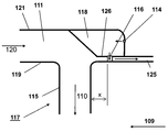
도 1은 희석 가스를 혼합하기 위한 댐퍼 믹서를 구비한 순차식 연소 설비를 구비한 일반적인 가스 터빈을 도시한 도면;
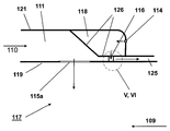
도 2는 주입 개구들과 댐퍼를 구비한 믹서를 갖는 순차식 연소기 설비를 도시한 도면;
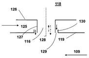
도 3은 댐퍼 목부의 하류에서 고온 가스 유동 내로 주입 튜브를 통하여 희석 가스를 공급하기 위한 연결 덕트를 갖는 믹서의 예를 보다 상세하게 도시한 도면;
도 4는 댐퍼 목부의 하류에서 주입 노즐을 통하여 희석 가스를 공급하기 위한 연결 덕트를 갖는 믹서의 또 다른 예를 보다 상세하게 도시한 도면;
도 5는 믹서 벽에 대한 댐퍼 연결을 위한 예의 단면을 클로즈업한 도면;
도 6은 믹서 벽에 대한 댐퍼 연결을 위한 또 다른 예의 단면을 클로즈업한 도면;
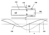
도 7은 감쇠가 없는 맥동파 및 시프팅 및 감쇠 후에 맥동파의 위치를 나타내는 믹서를 도시한 도면.The invention, its characteristics as well as its advantages, will now be described in more detail with the aid of the accompanying drawings. Referring to the drawings:
BRIEF DESCRIPTION OF THE DRAWINGS FIG. 1 shows a general gas turbine equipped with a sequential combustion plant with a damper mixer for mixing diluent gases; FIG.
Figure 2 shows a sequential combustor arrangement with a mixer with injection openings and a damper;
3 shows in greater detail an example of a mixer having a connecting duct for supplying a dilution gas through an inlet tube into a hot gas flow downstream of the damper neck;
4 shows in further detail another example of a mixer having a connecting duct for feeding dilution gas through an injection nozzle downstream of the damper neck;
5 is a close-up of an example section for damper connection to a mixer wall;
Figure 6 is a close-up of another example cross-section for damper connection to the mixer wall;
Figure 7 shows a pulse wave without attenuation and a mixer showing the position of the pulsed wave after shifting and attenuation.
도 1은 본 발명에 따른 순차식 연소기 설비(104)를 갖는 가스 터빈(100)을 도시한다. 가스 터빈은 압축기(103), 순차식 연소기 설비(104), 및 터빈(105)을 포함한다. 순차식 연소기 설비(104)는 제1 버너(112), 제1 연소실(101), 및 작동 동안 제1 연소실(101)을 떠나는 고온 가스에 희석 가스를 혼합하기 위한 믹서(117)를 포함한다(도 2 참조). 믹서(117)의 하류에서, 순차식 연소기 설비(104)는 제2 버너(113), 및 제2 연소실(102)을 추가로 포함한다. 제1 버너(112), 제1 연소실(101), 믹서(117), 제2 버너(113) 및 제2 연소실(102)은 유체 유동 연결에서 순차적으로 배열된다. 연료는 제1 연료 주입기(123)를 통해 제1 버너(112) 내로 도입되어, 압축기(103)에서 압축된 압축 공기(108)와 혼합되고, 제1 연소실(101)에서 연소될 수 있다. 압축기 플레넘(133)으로부터 희석 가스 공급부(122)를 통해 공급되는 희석 가스는 후속의 믹서(117)에서 혼합된다. 추가의 연료는 제2 연료 주입기(124)를 통해 제2 버너로 도입되어, 믹서(117)를 떠나는 고온 가스와 혼합되고, 제2 연소실(102)에서 연소될 수 있다. 제2 연소실(102)을 떠나는 고온 가스는 후속의 터빈(105)에서 팽창되고, 작업을 수행한다. 터빈(105)과 압축기(103)는 샤프트(106) 상에 배열된다.1 shows a
터빈(105)을 떠나는 배기 가스(107)의 나머지 열은 증기 발생을 위하여 열회수 증기 발생기 또는 보일러(도시되지 않음)에서 추가로 사용될 수 있다.The remaining heat of the
여기에 도시된 예에서, 압축기 배출 가스는 희석 가스와 혼합된다. 전형적으로, 압축기 배출 가스는 압축된 주위 공기이다. 연도 가스 순환(도시되지 않음)을 갖는 가스 터빈에 대하여, 압축기 배출 가스는 주위 공기와 재순환된 연도 가스의 혼합물이다. 공기는 산소를 포함하는 임의의 가스를 나타내는 것으로서 사용된다. In the example shown here, the compressor discharge gas is mixed with a diluent gas. Typically, the compressor discharge gas is compressed ambient air. For a gas turbine having a flue gas cycle (not shown), the compressor discharge gas is a mixture of ambient air and recycled flue gas. Air is used to denote any gas containing oxygen.
전형적으로, 가스 터빈 시스템은 가스 터빈(100)의 샤프트(106)에 결합된 발전기(도시되지 않음)를 포함한다. Typically, the gas turbine system includes a generator (not shown) coupled to the
도 2는 도 1의 확대된 섹션으로서 믹서(117)의 예시적인 실시예를 도시한다. 이 실시예에서, 압축기 플레넘(133)으로부터의 압축 공기(도 1 참조, 압축기(103)의 하류측의 압축 가스)는 희석 가스 공급부(122)(오직 도 1에만 도시됨)를 통해 공급되고, 희석 가스(110)로서 연결 덕트(111)에서 연소기 라이너를 따라서 가이드된다. 연결 덕트(111)로부터, 희석 가스(110)는 주입 튜브(115)를 통해 믹서(117) 내로 주입된다. 희석 가스(111)로 믹서 벽(119)을 냉각하고 주입 튜브(115)들을 이송하기 위하여, 덕트 벽(121)은 믹서 벽(119)에 평행하게 배열된다.FIG. 2 shows an exemplary embodiment of a
댐퍼는 이 예에서 주입 튜브(115)들로서 도시된 희석 가스 주입 개구(115, 115a)들 가까이 배열된다. 댐퍼는 댐퍼 체적부(118)를 한정하는 댐퍼 벽(126)과, 댐퍼 목부(116)를 포함한다. 목부(116)는 댐퍼 체적부(118)와 고온 가스 유동(109) 사이의 유체 소통을 위하여 댐퍼 체적부(118)와 결합된다.The damper is arranged close to the diluent
믹서는 환상 단면, 직사각형 또는 사다리꼴 단면 또는 원형을 가질 수 있다. 원형 단면을 갖는 원통형 믹서(117)의 예에 대하여, 지름은 유압 지름(D)과 동일하다. The mixer may have an annular cross section, a rectangular or trapezoidal cross section, or a round shape. For the example of the
도 3은 도 2로부터 희석 가스 주입 및 댐퍼 영역(Ⅲ, Ⅳ)을 보다 상세하게 도시한다. 상류(고온 가스 유동 방향으로)에서, 믹서(117)의 측벽(119)은 댐퍼 벽(126)에 의해 둘러싸이고, 믹서(117)의 유입 섹션을 냉각하기 위한 환상 냉각 덕트(125)를 형성한다. 그러므로, 댐퍼 체적부(118)는 고온 가스 유동(109)으로부터 분리된다. 퍼지 공기는 댐퍼 체적부(118) 내로 퍼지 가스 공급부(114)를 통해 댐퍼로 공급되고 목부(116)를 퍼지한다. 목부(116)는 희석 주입까지 일정 거리(x)만큼 편심된다. 희석 주입까지의 거리(x)는 튜브(115)의 배출 개구를 향하여 댐퍼가 맥동의 노드를 시프팅하는 것을 가능하게 하도록 믹서의 거리에 대해 작게 유지될 것이다. Fig. 3 shows the diluent gas injection and damper areas III and IV in more detail from Fig. In the upstream (in the hot gas flow direction), the
도 4는 도 3에 기초한다. 주입 튜브(115) 대신에, 주입 노즐(115)이 도 4에 도시된다.Fig. 4 is based on Fig. Instead of the
도 5는 댐퍼 체적부(118)를 고온 가스 유동(109)에 연결하는 목부(116)의 예를 도시한다. 목부 벽(127)은 목부 체적부를 한정한다. 이 예에서, 목부(116)는 믹서 벽(119)에 부착되고, 냉각 덕트(125)를 통해 댐퍼 체적부(118)를 향하여 연장한다. 추가하여, 댐퍼는 목부 벽(127)과 댐퍼 벽(126) 사이의 갭(129)을 포함한다. 선택적으로, 플랜지(130)는 갭(129)의 경계를 정하도록 댐퍼 벽(126)의 개구에 제공된다. 원통형 목부(116)는 목부 축(128)에 의해 지시된다. 이 경우에, 환상 갭(129)은 목부 벽(127)을 둘러싼다. 갭은 냉각 공기(125)에 의해 퍼지될 수 있다.Figure 5 shows an example of a
도 6은 도 5에 기초한다. 이 예에서, 목부 벽(127)은 댐퍼 벽(126)에 부착되고, 갭(129)은 목부 벽(127)과 믹서 벽(119) 사이에 제공된다. 플랜지(130)는 갭(129)의 경계를 정하도록 믹서 벽(119)의 개구에 제공된다. 갭은 냉각 공기(125)에 의해 퍼지될 수 있다.Fig. 6 is based on Fig. In this example, a
도 7에서, 믹서(117)에 있는 고온 가스 유동(109)에서 맥동파(131)의 위치는 주입 개구(115)와 목부(116)의 위치에 대해 지시된다. 점선은 댐퍼 체적부(118)가 없는 초기 맥동파(131)를 지시한다. 실선은 시프팅된 맥동파(132)를 지시한다. 시프팅된 맥동파(132)는 댐퍼의 효과로 인하여 맥동파 노드(s)의 시프팅에 의해 변위된다. 감쇠 효과로 인하여, 시프팅된 맥동파(132)의 진폭은 초기 맥동파(131)의 진폭에 대하여 감소된다. 주입 개구(115)에서 결과적인 맥동은 예를 들어 댐퍼가 없는 것보다 10배 작다. 7, the position of the
설명된 모든 이점들은 단지 명시된 조합으로 한정되지 않고 본 발명의 범위를 벗어남이 없이 다른 조합에서 또는 단독으로 사용될 수 있다. 다른 가능성들은 예를 들어 연소기 설비의 맥동 거동을 변경하도록 개별 버너 또는 버너의 다른 그룹들을 비활성화하기 위하여 고려할 수 있다. 또한, 희석 가스는 믹서에서 혼합 전에 공기 냉각기에서 다시 냉각될 수 있다. 또한, 2개 이상의 댐퍼들이 주입 개구(115, 115a)들 가까이에 배열될 수 있다. 댐퍼들은 하나의 맥동 진동수를 감쇠시키고 시프팅하도록 디장될 수 있거나, 또는 다수의 댐퍼들 중 다른 댐퍼들은 다른 맥동 진동수들을 감쇠시키고 시프팅하도록 디자인될 수 있다.All of the advantages described are not limited to just the specified combinations and can be used in other combinations or alone without departing from the scope of the present invention. Other possibilities may be considered to deactivate individual burners or other groups of burners, for example to change the pulsation behavior of the combustor installation. The diluent gas may also be cooled again in the air cooler before mixing in the mixer. In addition, two or more dampers may be arranged near the
100
가스 터빈
101
제1 연소기
102
제2 연소기
103
압축기
104
순차식 연소기 설비
105
터빈
106
샤프트
107
배기 가스
108
압축 공기
109
고온 가스 유동
110
희석 가스
111
연결 덕트
112
제1 버너
113
제2 버너
114
퍼지 가스 공급부
115
주입 튜브
115a
주입 노즐
116
목부
117
믹서
118
댐퍼 체적부
119
믹서 벽
120
냉각 가스
121
덕트 벽
122
희석 가스 공급부
123
제1 연료 주입기
124
제2 연료 주입기
125
냉각 덕트
126
댐퍼 벽
127
목부 벽
128
목부 축
129
갭
130
플랜지
131
맥동파
132
시프팅된 맥동파
133
압축기 플레넘
s
맥동파 노드의 시프팅
x
희석 주입까지의 거리
D
믹서의 유압 지름100
102
104
106
108
110
112
114 purge
117
119
121
123
125
127
129
131
133 Compressor Plenum s shifting of a Mac wave node
x Distance to dilution injection D Hydraulic diameter of the mixer
Claims (15)
상기 믹서(117)는, 상기 제1 연소실(101)을 떠나는 고온 연도 가스를 냉각하도록 희석 가스(110)를 혼합하기 위한 적어도 하나의 주입 개구(115, 115a), 및 댐퍼 체적부(118)를 둘러싸는 댐퍼 벽(126)과 상기 믹서(117)에 상기 댐퍼 체적부(118)를 연결하는 목부(116)를 포함하며, 상기 믹서(117) 내부의 압력 맥동을 감쇠시키는 댐퍼를 포함하는 것을 특징으로 하는 순차식 연소기 설비.A first burner 112, a first combustion chamber 101, a mixer 117 for mixing the dilution gas into the hot gas leaving the first combustion chamber 101 during operation, The burner 113 and the second combustion chamber 102. The mixer 117 guides the combustion gas in a hot gas flow path extending between the first combustion chamber 101 and the second burner 113, (104), comprising:
The mixer 117 includes at least one injection opening 115 and 115a for mixing the dilution gas 110 to cool the hot flue gas leaving the first combustion chamber 101 and a damper volume 118 And a dam 116 for dampering the pressure pulsation inside the mixer 117. The damper damper wall 126 includes a neck portion 116 connecting the damper body portion 118 to the mixer 117, Of a combustion chamber.
상기 믹서 벽(119)에 있는 상기 고온 가스 유동 경로까지의 상기 주입 개구(115, 115a)와 상기 목부(116)의 개구 사이에서 상기 고온 가스 유동의 유동 방향에서의 거리는 상기 믹서(117)에서 현저한 맥동의 파장의 1/6 미만인 것을 특징으로 하는 순차식 연소기 설비.The method of claim 1 wherein the distance in the flow direction of the hot gas flow between the injection opening (115, 115a) and the opening of the neck (116) to the hot gas flow path in the mixer wall (119) Is less than three times the hydraulic diameter (D) of the mixer at the opening of the mixer wall (116) and / or the injection openings (115, 115a) to the hot gas flow path in the mixer wall (119) 116 is less than the hydraulic diameter D of the mixer at the opening of the neck 116, and / or
The distance in the flow direction of the hot gas flow between the injection openings 115,115a to the hot gas flow path in the mixer wall 119 and the opening in the neck 116 is significant in the mixer 117 Wherein the wavelength of the pulsation is less than 1/6 of the wavelength of the pulsation.
상기 가스 터빈 엔진은 제1항 내지 제11항 중 어느 한 항에 따른 순차식 연소기 설비(104)를 포함하는 것을 특징으로 하는 가스 터빈 엔진.A gas turbine engine (100) having at least one compressor (103), a combustor, and at least one turbine (105)
Characterized in that the gas turbine engine comprises a sequential combustor arrangement (104) according to any of the preceding claims.
상기 믹서(117)의 내부의 맥동파(132)의 노드는 상기 댐퍼에 의해 상기 주입 개구(115, 115a)들을 향해 시프팅되는 것을 특징으로 하는 가스 터빈 작동 방법.At least one compressor (103); A first combustion chamber 101, a mixer 117 for mixing a dilution gas into a high temperature gas leaving the first combustion chamber 101 during operation, 2 includes a burner 113 and a sequential combustor arrangement 104 including a second combustion chamber 102. The mixer 117 is arranged between the first combustion chamber 101 and the second burner 113, Wherein the mixer is adapted to guide the combustion gas in a hot gas flow path extending from the first combustion chamber and the mixer is adapted to mix the diluent gas to cool the hot flue gas leaving the first combustion chamber, At least one injection opening (115,115a) in the mixer (117) and a damper for attenuating the pressure pulsation inside the mixer (117), the damper comprising a damper volume (118) And a neck portion (116) connecting the damper volume portion (118). The gas turbine (100) A method for Pointing,
Characterized in that the node of the pulsation wave (132) inside the mixer (117) is shifted by the damper towards the injection openings (115, 115a).
Applications Claiming Priority (2)
| Application Number | Priority Date | Filing Date | Title |
|---|---|---|---|
| EP15152897.3A EP3051206B1 (en) | 2015-01-28 | 2015-01-28 | Sequential gas turbine combustor arrangement with a mixer and a damper |
| EP15152897.3 | 2015-01-28 |
Publications (1)
| Publication Number | Publication Date |
|---|---|
| KR20160092939A true KR20160092939A (en) | 2016-08-05 |
Family
ID=52434598
Family Applications (1)
| Application Number | Title | Priority Date | Filing Date |
|---|---|---|---|
| KR1020160009896A KR20160092939A (en) | 2015-01-28 | 2016-01-27 | Sequential combustor arrangement with a mixer |
Country Status (6)
| Country | Link |
|---|---|
| US (1) | US10451283B2 (en) |
| EP (1) | EP3051206B1 (en) |
| JP (1) | JP2016156608A (en) |
| KR (1) | KR20160092939A (en) |
| CN (1) | CN105823085B (en) |
| TW (1) | TW201638530A (en) |
Cited By (1)
| Publication number | Priority date | Publication date | Assignee | Title |
|---|---|---|---|---|
| KR102164620B1 (en) * | 2019-06-19 | 2020-10-12 | 두산중공업 주식회사 | Combustor and gas turbine including the same |
Families Citing this family (12)
| Publication number | Priority date | Publication date | Assignee | Title |
|---|---|---|---|---|
| CN104541104A (en) * | 2012-08-24 | 2015-04-22 | 阿尔斯通技术有限公司 | Sequential combustion with dilution gas mixer |
| EP2865947B1 (en) * | 2013-10-28 | 2017-08-23 | Ansaldo Energia Switzerland AG | Damper for gas turbine |
| US20150159877A1 (en) * | 2013-12-06 | 2015-06-11 | General Electric Company | Late lean injection manifold mixing system |
| EP3369995B1 (en) * | 2017-03-02 | 2020-08-05 | Ansaldo Energia Switzerland AG | Method of flow oscillation cancellation in a mixer |
| EP3486566A1 (en) * | 2017-11-15 | 2019-05-22 | Ansaldo Energia Switzerland AG | Gas turbine comprising a can combustor provided with a damper |
| CN110030578A (en) * | 2017-11-15 | 2019-07-19 | 安萨尔多能源瑞士股份公司 | Barrel type burner for gas turbine and the gas turbine including this barrel type burner |
| RU2755240C2 (en) * | 2017-12-26 | 2021-09-14 | Ансальдо Энергия Свитзерленд Аг | Burner for combustion chamber of gas turbine power plant, combustion chamber of gas turbine power plant containing such burner, and gas turbine power plant containing such combustion chamber |
| WO2019188656A1 (en) * | 2018-03-29 | 2019-10-03 | テルモ株式会社 | Control apparatus for medical device and method of controlling flow rate of fluid |
| EP3657074B1 (en) * | 2018-11-26 | 2021-06-23 | Ansaldo Energia Switzerland AG | Method for manufacturing a burner lance |
| US11174792B2 (en) | 2019-05-21 | 2021-11-16 | General Electric Company | System and method for high frequency acoustic dampers with baffles |
| US11156164B2 (en) | 2019-05-21 | 2021-10-26 | General Electric Company | System and method for high frequency accoustic dampers with caps |
| EP4202306A1 (en) * | 2021-12-27 | 2023-06-28 | Ansaldo Energia Switzerland AG | Premix burner for a gas turbine assembly for power plant provided with a pilot lance suitable to be fed with common and highly reactive fuels, method for operating this burner and gas turbine assembly for power plant comprising this burner |
Family Cites Families (26)
| Publication number | Priority date | Publication date | Assignee | Title |
|---|---|---|---|---|
| US2642204A (en) * | 1952-01-04 | 1953-06-16 | Walter J Dixon | Permanently attached closure device for containers |
| DE4417538A1 (en) * | 1994-05-19 | 1995-11-23 | Abb Management Ag | Combustion chamber with self-ignition |
| DE4426351B4 (en) * | 1994-07-25 | 2006-04-06 | Alstom | Combustion chamber for a gas turbine |
| EP0990851B1 (en) * | 1998-09-30 | 2003-07-23 | ALSTOM (Switzerland) Ltd | Gas turbine combustor |
| US6351947B1 (en) * | 2000-04-04 | 2002-03-05 | Abb Alstom Power (Schweiz) | Combustion chamber for a gas turbine |
| US6530221B1 (en) | 2000-09-21 | 2003-03-11 | Siemens Westinghouse Power Corporation | Modular resonators for suppressing combustion instabilities in gas turbine power plants |
| US6973790B2 (en) | 2000-12-06 | 2005-12-13 | Mitsubishi Heavy Industries, Ltd. | Gas turbine combustor, gas turbine, and jet engine |
| US6672067B2 (en) * | 2002-02-27 | 2004-01-06 | General Electric Company | Corrugated cowl for combustor of a gas turbine engine and method for configuring same |
| GB2390150A (en) * | 2002-06-26 | 2003-12-31 | Alstom | Reheat combustion system for a gas turbine including an accoustic screen |
| DE10312971B4 (en) | 2003-03-24 | 2017-04-06 | General Electric Technology Gmbh | Method for operating a gas turbine group |
| CN100504174C (en) * | 2003-12-16 | 2009-06-24 | 株式会社日立制作所 | Combustor for gas turbine |
| GB0427147D0 (en) | 2004-12-11 | 2005-01-12 | Rolls Royce Plc | Combustion chamber for a gas turbine engine |
| US7461719B2 (en) * | 2005-11-10 | 2008-12-09 | Siemens Energy, Inc. | Resonator performance by local reduction of component thickness |
| US8265111B2 (en) * | 2008-03-18 | 2012-09-11 | Mitsubishi Electric Corporation | Laser light source module |
| WO2010097982A1 (en) | 2009-02-27 | 2010-09-02 | 三菱重工業株式会社 | Combustor and gas turbine with same |
| FR2958016B1 (en) * | 2010-03-23 | 2017-03-24 | Snecma | METHOD OF REDUCING COMBUSTION INSTABILITIES BY CHOOSING THE POSITIONING OF AIR TANK ON A TURBOMACHINE |
| EP2385303A1 (en) * | 2010-05-03 | 2011-11-09 | Alstom Technology Ltd | Combustion Device for a Gas Turbine |
| EP2397760B1 (en) | 2010-06-16 | 2020-11-18 | Ansaldo Energia IP UK Limited | Damper Arrangement and Method for Designing Same |
| US9010119B2 (en) * | 2010-11-03 | 2015-04-21 | General Electric Company | Premixing nozzle |
| US8966903B2 (en) | 2011-08-17 | 2015-03-03 | General Electric Company | Combustor resonator with non-uniform resonator passages |
| US20130074471A1 (en) | 2011-09-22 | 2013-03-28 | General Electric Company | Turbine combustor and method for temperature control and damping a portion of a combustor |
| EP2642204A1 (en) * | 2012-03-21 | 2013-09-25 | Alstom Technology Ltd | Simultaneous broadband damping at multiple locations in a combustion chamber |
| CN104541104A (en) * | 2012-08-24 | 2015-04-22 | 阿尔斯通技术有限公司 | Sequential combustion with dilution gas mixer |
| KR20150074155A (en) * | 2012-10-24 | 2015-07-01 | 알스톰 테크놀러지 리미티드 | Sequential combustion with dilution gas mixer |
| EP2837782A1 (en) * | 2013-08-14 | 2015-02-18 | Alstom Technology Ltd | Damper for combustion oscillation damping in a gas turbine |
| EP2894405B1 (en) * | 2014-01-10 | 2016-11-23 | General Electric Technology GmbH | Sequential combustion arrangement with dilution gas |
-
2015
- 2015-01-28 EP EP15152897.3A patent/EP3051206B1/en active Active
-
2016
- 2016-01-08 TW TW105100602A patent/TW201638530A/en unknown
- 2016-01-27 US US15/007,981 patent/US10451283B2/en active Active
- 2016-01-27 KR KR1020160009896A patent/KR20160092939A/en unknown
- 2016-01-28 CN CN201610057723.4A patent/CN105823085B/en active Active
- 2016-01-28 JP JP2016014517A patent/JP2016156608A/en active Pending
Cited By (2)
| Publication number | Priority date | Publication date | Assignee | Title |
|---|---|---|---|---|
| KR102164620B1 (en) * | 2019-06-19 | 2020-10-12 | 두산중공업 주식회사 | Combustor and gas turbine including the same |
| US11248792B2 (en) | 2019-06-19 | 2022-02-15 | Doosan Heavy Industries & Construction Co., Ltd. | Combustor and gas turbine including the same |
Also Published As
| Publication number | Publication date |
|---|---|
| EP3051206A1 (en) | 2016-08-03 |
| US20160215984A1 (en) | 2016-07-28 |
| TW201638530A (en) | 2016-11-01 |
| US10451283B2 (en) | 2019-10-22 |
| CN105823085A (en) | 2016-08-03 |
| JP2016156608A (en) | 2016-09-01 |
| CN105823085B (en) | 2020-07-07 |
| EP3051206B1 (en) | 2019-10-30 |
Similar Documents
| Publication | Publication Date | Title |
|---|---|---|
| KR20160092939A (en) | Sequential combustor arrangement with a mixer | |
| US10502423B2 (en) | Sequential combustion with dilution gas | |
| EP1672282B1 (en) | Method and apparatus for decreasing combustor acoustics | |
| RU2562132C2 (en) | Mixing method of dilution air in subsequent combustion system of gas turbine | |
| US9140454B2 (en) | Bundled multi-tube nozzle for a turbomachine | |
| US10215417B2 (en) | Sequential combustor arrangement with a mixer | |
| EP3037728B1 (en) | Axially staged mixer with dilution air injection | |
| CN105715378B (en) | Separate supply of cooling and dilution air | |
| RU2570480C2 (en) | Mixing of diluting air in gas turbine sequential combustion system | |
| JP2016516975A (en) | Multistage combustion with dilution gas | |
| JP2016128741A (en) | Mixer for admixing dilution air to hot gas flow | |
| EP2989389B1 (en) | Sequential combustion with dilution gas |
Legal Events
| Date | Code | Title | Description |
|---|---|---|---|
| N231 | Notification of change of applicant |