KR20160081923A - Agitator for mixing fluids - Google Patents
Agitator for mixing fluids Download PDFInfo
- Publication number
- KR20160081923A KR20160081923A KR1020167012848A KR20167012848A KR20160081923A KR 20160081923 A KR20160081923 A KR 20160081923A KR 1020167012848 A KR1020167012848 A KR 1020167012848A KR 20167012848 A KR20167012848 A KR 20167012848A KR 20160081923 A KR20160081923 A KR 20160081923A
- Authority
- KR
- South Korea
- Prior art keywords
- paddle
- shaft
- paddles
- main shaft
- shafts
- Prior art date
Links
Images


Classifications
-
- B—PERFORMING OPERATIONS; TRANSPORTING
- B01—PHYSICAL OR CHEMICAL PROCESSES OR APPARATUS IN GENERAL
- B01F—MIXING, e.g. DISSOLVING, EMULSIFYING OR DISPERSING
- B01F27/00—Mixers with rotary stirring devices in fixed receptacles; Kneaders
- B01F27/80—Mixers with rotary stirring devices in fixed receptacles; Kneaders with stirrers rotating about a substantially vertical axis
- B01F27/95—Mixers with rotary stirring devices in fixed receptacles; Kneaders with stirrers rotating about a substantially vertical axis with stirrers having planetary motion, i.e. rotating about their own axis and about a sun axis
-
- B01F7/30—
-
- B01F15/00487—
-
- B—PERFORMING OPERATIONS; TRANSPORTING
- B01—PHYSICAL OR CHEMICAL PROCESSES OR APPARATUS IN GENERAL
- B01F—MIXING, e.g. DISSOLVING, EMULSIFYING OR DISPERSING
- B01F23/00—Mixing according to the phases to be mixed, e.g. dispersing or emulsifying
-
- B—PERFORMING OPERATIONS; TRANSPORTING
- B01—PHYSICAL OR CHEMICAL PROCESSES OR APPARATUS IN GENERAL
- B01F—MIXING, e.g. DISSOLVING, EMULSIFYING OR DISPERSING
- B01F27/00—Mixers with rotary stirring devices in fixed receptacles; Kneaders
- B01F27/05—Stirrers
- B01F27/11—Stirrers characterised by the configuration of the stirrers
- B01F27/112—Stirrers characterised by the configuration of the stirrers with arms, paddles, vanes or blades
- B01F27/1125—Stirrers characterised by the configuration of the stirrers with arms, paddles, vanes or blades with vanes or blades extending parallel or oblique to the stirrer axis
- B01F27/11253—Stirrers characterised by the configuration of the stirrers with arms, paddles, vanes or blades with vanes or blades extending parallel or oblique to the stirrer axis the blades extending oblique to the stirrer axis
-
- B—PERFORMING OPERATIONS; TRANSPORTING
- B01—PHYSICAL OR CHEMICAL PROCESSES OR APPARATUS IN GENERAL
- B01F—MIXING, e.g. DISSOLVING, EMULSIFYING OR DISPERSING
- B01F27/00—Mixers with rotary stirring devices in fixed receptacles; Kneaders
- B01F27/80—Mixers with rotary stirring devices in fixed receptacles; Kneaders with stirrers rotating about a substantially vertical axis
- B01F27/90—Mixers with rotary stirring devices in fixed receptacles; Kneaders with stirrers rotating about a substantially vertical axis with paddles or arms
-
- B01F3/00—
-
- B—PERFORMING OPERATIONS; TRANSPORTING
- B01—PHYSICAL OR CHEMICAL PROCESSES OR APPARATUS IN GENERAL
- B01F—MIXING, e.g. DISSOLVING, EMULSIFYING OR DISPERSING
- B01F35/00—Accessories for mixers; Auxiliary operations or auxiliary devices; Parts or details of general application
- B01F35/30—Driving arrangements; Transmissions; Couplings; Brakes
- B01F35/32—Driving arrangements
- B01F35/32005—Type of drive
-
- B01F7/18—
-
- B—PERFORMING OPERATIONS; TRANSPORTING
- B01—PHYSICAL OR CHEMICAL PROCESSES OR APPARATUS IN GENERAL
- B01F—MIXING, e.g. DISSOLVING, EMULSIFYING OR DISPERSING
- B01F2215/00—Auxiliary or complementary information in relation with mixing
- B01F2215/04—Technical information in relation with mixing
- B01F2215/0413—Numerical information
- B01F2215/0418—Geometrical information
- B01F2215/0422—Numerical values of angles
Abstract
본 발명은 다양한 점도를 갖는 유체들을 혼합하기 위한 교반기에 관한 것으로서, 상기 교반기(1)는 회전축(6)을 가진 메인 샤프트(4) 및 상기 메인 샤프트(4)와 연결된 패들(20)들을 구비한 바이오닉 교반기(bionic agitor)이고, 상기 패들(20)들 각각은 하나의 패들 샤프트 축(28)을 가진 하나의 패들 샤프트(15)를 구비하며, 상기 샤프트 축(28)들은 상기 회전축(6)에 대한 20° 내지 40° 범위의 제1 각도(α)를 가지고, 패들 표면(30)을 가진 패들(20)들은 서로에 대해서 90°인 제2 각도(β)로 배치되며, 교반기(1)의 작동시 상기 패들(20)들은 메인 샤프트(4)를 중심으로 하는 제1 회전과 개별의 패들 샤프트 축(28)을 중심으로 하는 제2 회전을 수행한다. 본 발명에 따르면, 메인 샤프트(4)로부터 멀리 향하도록 형성된 패들 샤프트(15)들의 저부 단부(21)에서 회전축(6)에 대한 상기 샤프트 축(28)들의 제1 반경방향 거리는, 메인 샤프트(4)를 향하도록 형성된 패들 샤프트(15)들의 상측 단부에서 회전축(6)에 대한 상기 샤프트 축(28)들의 제2 반경방향 거리보다 더 크다.The present invention relates to an agitator for mixing fluids having various viscosities, wherein the agitator (1) comprises a main shaft (4) having a rotating shaft (6) and paddles (20) connected to the main shaft Wherein each of the paddles (20) has a paddle shaft (15) having a paddle shaft shaft (28), the shaft axes (28) being connected to the rotating shaft The paddles 20 with the paddle surface 30 are arranged at a second angle beta of 90 DEG relative to each other with a first angle alpha in the range of 20 DEG to 40 DEG with respect to each other, In operation, the paddles 20 perform a first rotation about the main shaft 4 and a second rotation about a respective paddle shaft axis 28. The first radial distance of the shaft axes 28 relative to the rotational axis 6 at the bottom end 21 of the paddle shafts 15 directed away from the main shaft 4 is greater than the first radial distance of the main shaft 4 Of the shaft shafts 28 relative to the rotary shaft 6 at the upper end of the paddle shafts 15 that are formed so as to face the pivot shafts 15 facing each other.
Description
본 발명은 청구항 1 에 기재된 바와 같이, 다양한 점도를 갖는 유체들을 혼합하기 위한 교반기에 관한 것이다.The present invention relates to an agitator for mixing fluids having various viscosities, as described in
유체들을 교반 또는 혼합하기 위한 교반기는 공지되어 있다. 교반 또는 혼합 각각을 위하여, 유체 프로펠러 또는 변형된 프로펠러가 사용되는데, 이들이 교반기로 호칭된다. 프로펠러 또는 변형된 프로펠러는 샤프트를 중심으로 동등하게 이격되어 있는 둘 이상의 블레이드(blade) 또는 패들로 이루어진 장치로서 이해된다. 상기 블레이드들 또는 패들들이 상기 샤프트를 중심으로 회전하는 동안에 상기 프로펠러가 유체들을 혼합한다.Stirrers for stirring or mixing fluids are known. For each stirring or mixing, a fluid propeller or a modified propeller is used, which is referred to as a stirrer. A propeller or modified propeller is understood to be a device consisting of two or more blades or paddles equally spaced about a shaft. The propeller mixes the fluids while the blades or paddles rotate about the shaft.
프로펠러를 구비한 교반기는 다양한 유체를 혼합시키기 위하여 사용된다. 예를 들어, 특허 문헌 CH 690836 A5 에는 밀가루반죽을 교반하기 위한 교반기가 개시되어 있는데, 여기에서는 발생된 유동 거동에 영향을 주기 위하여 블레이드들 또는 패들들에 추가적인 요소가 부착된다.Agitators with propellers are used to mix various fluids. For example, the patent document CH 690836 A5 discloses a stirrer for stirring dough, wherein additional elements are attached to the blades or paddles to affect the flow behavior that is generated.
실용신안 문헌 AT 007987 U1 에는 바이오매스(biomass), 하수 슬러지, 등을 위한 교반기가 개시되어 있는데, 그것의 프로펠러 축 또는 구동 샤프트는 유체의 우수한 공간적 혼합을 얻기 위하여 수평에 대해 다양한 각도를 취한다.Utility model AT 007987 U1 discloses a stirrer for biomass, sewage sludge, etc. whose propeller shaft or drive shaft takes various angles with respect to the horizontal to obtain good spatial mixing of the fluid.
교반기의 움직임가능한 프로펠러로서, 구동축을 따라서 길이방향으로 움직여질 수 있는 프로펠러는 실용신안 문헌 DE 20 2008 015 990 U1 에 개시되어 있다. 축이 경사를 이룰 수 있는 프로펠러는 특허 문헌 DE 197 56 485 C2 에 개시되어 있다.A propeller capable of being moved longitudinally along a drive shaft as a moveable propeller of an agitator is disclosed in utility model document DE 20 2008 015 990 U1. A propeller in which the shaft can be inclined is disclosed in patent document DE 197 56 485 C2.
심사받지 않은 특허 문헌 DE 10 2010 002 461 A1에 개시되어 있는 교반기는 수개의 개구들을 가진 쉬라우드(shroud)에 의하여 둘러싸여 있어서, 채널을 통하여 유체가 흡입 또는 가압됨으로써 움직임이 발생한다.The stirrer disclosed in the undeclared
상기 프로펠러의 다양한 구성형태 채택에 부가하여, DE 91 02 832 U1, DE 20 2011 052 408 U1, DE 20 2011 107 055 U1, DE 6 910 714 T2, 또는 DE 88 11 813 U1 와 같은 문헌에는 유체들을 혼합하기 위하여 사용된 다른 형태도 개시되어 있다.In addition to adopting various configurations of the propeller, references such as DE 91 02 832 U1, DE 20 2011 052 408 U1, DE 20 2011 107 055 U1,
본 발명은 유체들의 개선된 혼합을 위한 교반기를 제공함을 목적으로 한다.The present invention aims to provide an agitator for improved mixing of fluids.
본 발명에 따르면 상기 목적은 청구항 1 의 구성을 가진 유체 혼합용 교반기에 의해 달성된다. 본 발명이 적절하게 구현된 유리한 실시예들은 종속항들 각각에 기재되어 있다.According to the present invention, this object is achieved by a stirrer for fluid mixing having the constitution of
다양한 점도를 갖는 유체들을 혼합하기 위한 본 발명의 교반기는 메인 샤프트(main shaft) 및 상기 메인 샤프트와 연결된 패들(paddle)들을 구비한 바이오닉 교반기(bionic agitor)로서, 상기 패들들 각각은 패들 샤프트 축을 가진 패들 샤프트를 구비한다. 상기 샤프트 축들은 상기 회전축에 대한 20° 내지 40° 범위의 제1 각도를 가진다. 상기 패들들은 패들 표면들이 서로에 대해서 90°인 제2 각도로 배치된다. 교반기의 작동시 상기 패들들은 메인 샤프트를 중심으로 하는 제1 회전과 개별의 패들 샤프트 축을 중심으로 하는 제2 회전을 수행한다. 메인 샤프트로부터 멀리 향하여 형성되어 있는 패들 샤프트들의 하측 단부에서의 회전축에 대한 샤프트 축들의 제1 반경방향 거리는, 메인 샤프트를 향하여 형성되어 있는 패들 샤프트들의 상측 단부에서의 회전축에 대한 샤프트 축들의 제2 반경방향 거리보다 더 크다. 이로 인한 장점으로서, 패들들의 영역에서 상기 패들들의 경사진 자세, 즉 메인 샤프트로부터 외부로 향하는 자세로 인하여, 유체 유동이 개선된다.The stirrer of the present invention for mixing fluids of various viscosities is a bionic agitor with a main shaft and paddles connected to the main shaft, each paddle having a paddle shaft axis And a paddle shaft. The shaft axes have a first angle in the range of 20 to 40 degrees with respect to the axis of rotation. The paddles are disposed at a second angle with the paddle surfaces at 90 [deg.] To each other. During operation of the agitator, the paddles perform a first rotation about the main shaft and a second rotation about an individual paddle shaft axis. The first radial distance of the shaft axes relative to the rotational axis at the lower end of the paddle shafts formed away from the main shaft is greater than the second radial distance of the shaft axes relative to the rotational axis at the upper end of the paddle shafts, It is bigger than the directional distance. As a result of this, the fluid flow is improved due to the inclined posture of the paddles in the region of the paddles, i.e., the posture directed outward from the main shaft.
본 기술분야에서 상기 패들들의 영역에서 패들들의 경사진 자세가 메인 샤프트로부터 내부를 향하는 자세, 즉 회전축을 향하는 패들들의 자세는 공지되어 있다. 패들들의 형상이 동일하다면, 본 발명에 의한 상기 패들들의 자세로 인하여 패들들이 외향으로 향하기 때문에 현저히 큰 원주상 반경이 얻어지며, 따라서 확장된 유동 반경이 얻어질 수 있으며, 이는 궁극적으로 유체 유동의 개선으로 이어져서 유체의 혼합이 향상되는 결과로 귀결된다.It is known in the art that the inclined posture of the paddles in the area of the paddles is inward from the main shaft, i.e., the posture of the paddles toward the rotation axis. If the shapes of the paddles are the same, a significantly larger circumferential radius is obtained because the paddles are directed outward due to the posture of the paddles according to the present invention, and thus an extended flow radius can be obtained, Resulting in improved mixing of the fluid.
일 실시예에서, 상기 제1 회전은 메인 샤프트와 패들들 간의 토크-전달 연결부(torque-transmitting connection)에 의하여 패들들로 전달될 수 있고, 상기 제2 회전은 상기 메인 샤프트와 패들들 사이에 배치되어 있는 마찰 구동부(friction drive)에 의하여 상기 패들들로 전달될 수 있다.In one embodiment, the first rotation can be transmitted to the paddles by a torque-transmitting connection between the main shaft and the paddles, and the second rotation is placed between the main shaft and the paddles And can be transmitted to the paddles by a friction drive.
바람직하게는, 상기 토크-전달 연결부가 패들 샤프트들을 회전가능하게 수용하는 제2 안내 튜브(second guide tube)들에 의해 형성되고, 상기 튜브들은 상기 메인 샤프트와 토크-전달 방식으로 연결되어 있다.Advantageously, the torque-transfer connection is formed by second guide tubes which rotatably receive the paddle shafts, the tubes being connected in a torque-transfer manner to the main shaft.
상기 토크-전달 연결부의 제작을 위하여, 상기 메인 샤프트와 토크-전달 방식으로 연결되어 있는 하우징(housing)에 제2 안내 튜브들이 토크-전달 방식으로 수용되는 것이 바람직하다. 이로 인하여 상기 안내 튜브들을 하우징에 고정시킬 수 있게 된다.In order to manufacture the torque-transmitting connection portion, it is preferable that the second guide tubes are received in a torque-transmitting manner in a housing connected to the main shaft in a torque-transmitting manner. This makes it possible to fix the guide tubes to the housing.
본 발명의 추가적인 실시예에 따르면, 상기 마찰 구동부는 기어들을 포함한다. 상기 기어들로 인하여, 바람직하게는 큰 힘이 전달될 수 있다.According to a further embodiment of the present invention, the friction drive comprises gears. Due to the gears, preferably a large force can be transmitted.
바람직하게는, 상기 기어들이 베벨 기어로서 형성되는데, 이로 인하여 상기 회전축에 대한 패들 샤프트 축의 경사진 자세가 간편하게 얻어질 수 있다.Preferably, the gears are formed as bevel gears, whereby a tilted posture of the paddle shaft axis relative to the rotation axis can be easily obtained.
추가적인 실시예에서는, 상기 마찰 구동부가 트랜스미션 기어 하우징 안에 수용되는데, 이로 인하여 임의의 유체 유입이 방지되며 또한 상기 트랜스미션 기어 하우징에 있는 밀봉재들에 의해 완전히 배제될 수 있다.In a further embodiment, the friction drive portion is received in the transmission gear housing, whereby any fluid inflow is prevented and can be completely eliminated by the seals in the transmission gear housing.
바람직하게는 상기 패들 샤프트들이 지지판을 구비한 안정화 튜브를 포함하는데, 상기 안정화 튜브에는 패들 샤프트의 추가적인 페더 키이를 위한 노치가 제공된다. 이것은 신속정확한 끼움맞춤식 조립을 가능하게 하고, 작동 중에 패들들이 그들 각각의 특정한 각도 또는 위치로부터 이탈될 수 없게 한다. 이와 같은 결합은 잠금부, 볼트, 및 다른 기계적인 나사식 연결부에 의하여 이루어질 수 있다.Preferably, the paddle shafts include a stabilization tube having a support plate, wherein the stabilization tube is provided with a notch for an additional feather key of the paddle shaft. This allows for rapid and precise fit assembly and prevents the paddles from being removed from their respective particular angles or positions during operation. Such a coupling can be achieved by means of locks, bolts, and other mechanical threaded connections.
본 발명의 교반기의 추가적인 실시예에서는, 상기 패들로부터 멀리 있는 패들 샤프트의 단부에 안정화 튜브와의 연결을 위한 페더 키이가 구비되며, 이로써 패들들이 지지된다. 이것은 상기 패들들의 안정화 튜브가 신속히 조립됨을 보장하고, 또한 상기 패들들의 움직임 시에 상기 패들의 안정화 튜브와 패들 샤프트 간의 연결이 미끄러짐을 방지한다. 대안적으로는, 모든 가능한 잠금부, 볼트, 및 다른 기계적인 나사방식의 연결부도 사용될 수 있다.In a further embodiment of the stirrer of the present invention, a feather key for connection to the stabilization tube is provided at the end of the paddle shaft remote from the paddle, whereby the paddles are supported. This ensures that the stabilization tubes of the paddles are assembled quickly and also prevents the connection between the stabilization tube of the paddles and the paddle shaft from slipping upon movement of the paddles. Alternatively, all possible locks, bolts, and other mechanical threaded connections may be used.
본 발명의 교반기의 추가적인 실시예에 따르면, 패들 샤프트들은 제2 안내 튜브 안에 회전가능하게 수용되고, 그들은 보강 수단을 거쳐서 작은 기어 비율의 트랜스미션 기어 하우징과 연결되며, 또한 그들은 복수의 베어링에 의해 지지되고 트랜스미션 기어 하우징에 대해 밀봉된다. 상기 제2 안내 튜브들로 인하여 안정성이 향상되고 부드러운 교반 거동이 얻어지기 때문에 유익하며, 동시에 유체가 하측 트랜스미션 기어 하우징 안으로 침투함이 방지되기 때문에 유익하다.According to a further embodiment of the stirrer of the present invention, the paddle shafts are rotatably received in a second guide tube, which are connected to a transmission gear housing of a small gear ratio via the means of reinforcement, and they are supported by a plurality of bearings And is sealed to the transmission gear housing. This is beneficial because the second guide tubes improve stability and gentle stirring behavior and are beneficial because fluid is prevented from infiltrating into the lower transmission gear housing.
본 발명의 추가적인 장점, 구성, 및 상세사항들은 본 발명의 예시적인 바람직한 실시예에 관한 하기의 설명 및 도면으로부터 명확히 이해될 것이다. 위에서 설명된 구성 및 구성들의 조합과, 하기의 설명 또는 도면에 기재된 구성 및 구성들의 조합은 해당의 실시예에만 적용가능한 것으로 국한되는 것이 아니며, 본 발명의 범위를 벗어나지 않는 한 다른 실시예에 단독으로 또는 다른 구성과 함께 조합되어 적용될 수 있다. 기능적으로 동일 또는 유사한 구성요소들에는 동일한 참조번호가 부여되었다. 명확성을 위하여, 모든 도면들에서 구성요소들의 모든 참조번호가 표시되지는 않았으나, 참조번호가 누락되지는 않았다.Additional advantages, features, and details of the present invention will become apparent from the following description and drawings taken in conjunction with the exemplary preferred embodiments of the invention. It is to be understood that both the foregoing description and combinations of elements and configurations described in the following description or drawings are not construed to limit the scope of the present invention to the specific embodiments disclosed and that the present invention may be embodied in other specific forms without departing from the scope of the present invention. Or in combination with other configurations. Functionally identical or similar components have been given the same reference numerals. For clarity, not all reference numerals of components are shown in all figures, but reference numerals are not omitted.
도 1 은 구동기를 구비한 본 발명의 교반기의 사시도이고,
도 2 는 도 1 의 교반기의 하측 트랜스미션 기어의 단면도이고,
도 3 은 도 2 의 하측 트랜스미션 기어의 사시도이고,
도 4 는 도 1 의 교반기의 패들의 사시도이고,
도 5 는 패들이 구비된 하측 트랜스미션 기어의 부분 단면도이고,
도 6 은 패들이 구비된 하측 트랜스미션 기어의 평면도이다.1 is a perspective view of an agitator of the present invention equipped with a driver,
2 is a sectional view of the lower transmission gear of the agitator of FIG. 1,
3 is a perspective view of the lower transmission gear of Fig. 2,
Figure 4 is a perspective view of the paddles of the agitator of Figure 1,
5 is a partial cross-sectional view of the lower transmission gear with paddles,
6 is a plan view of the lower transmission gear with paddles.
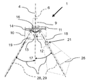
유체들을 혼합하기 위한 본 발명의 교반기(1), 특히 바이오닉 교반기는, 도 1 에 도시된 바와 같이 구성된다. 상기 교반기(1)는 작동가능한 구동부(2)를 포함한다. 상기 구동부(2)는 전기식, 공압식, 또는 유압식의 것으로서 설계될 수 있다. 도시된 에시적인 실시예에서, 상기 구동부(2)는 전기 모터로서 설계된다.The
대안적으로는, 물 또는 증기, 가솔린, 또는 다른 유형의 연소 엔진이 사용될 수 있다. 상기 바이오닉 교반기(1)의 구동부(2)는 목적뿐만 아니라, 혼합될 유체의 양 및 점도에 의하여 결정된다.Alternatively, water or steam, gasoline, or other types of combustion engines may be used. The
상기 구동부(2)는 트랜스미션 기어(transmission gear; 3)와 결합되고, 상기 트랜스미션 기어(3)는 교반기(1)의 메인 샤프트(4)를 구동하며, 상기 메인 샤프트(4)는 교반기(1)의 하측 트랜스미션 기어(5)와 연결된다 - 도 2 참조. 사용되는 기어 비율(gear ratio)은 목적과 각각의 유체에 따라 정해질 수 있다. 필요한 경우에는, 상기 기어 비율이 낮은 속도부터 높은 속도까지의 범위를 커버(cover)한다. 상기 기어 비율은, 개별 유체의 부드러운 혼합(gentle mixing)과 우수한 에너지 효율의 달성을 위하여 개별의 구동부(2)에 맞게 구성될 수 있다.The
상기 메인 샤프트(4)는 수 개의 베어링들에 의해 지지된다. 이와 같은 복수의 지지부들(multiple supports)로 인하여, 회전축(6)을 중심으로 하는 비교적 마찰이 없는 회전이 가능하게 된다. 또한, 상기 메인 샤프트(4)가 교반기(1)의 하중 전체를 부담하기 때문에, 상기 복수의 지지부들로 인하여 개별 베어링에 대한 하중 배분을 개선시킨다.The
메인 샤프트(4)에 대한 트랜스미션 기어(3)의 연결부의 정확한 끼움(exact fit)은 페더 키이(7)에 의하여 이루어진다.The exact fit of the connection of the
상기 바이오닉 교반기(1)의 조립을 위하여, 조립 플레이트(assembly plate; 8)가 제공된다. 상기 조립 플레이트(8)는, 나무, 콘크리트, 돌, 플라스틱, 또는 금속으로 이루어질 수 있고 조립을 위하여 제공되는 장치와 매우 높은 효율의 나사, 밀봉재, 및 베어링에 의하여 연결될 수 있다.In order to assemble the
본 예시적인 실시예에서, 조립 플레이트(8)는 예를 들어, 교반될 유체가 내부에 놓이는 폐쇄 공간(상세히 도시되지는 않음)의 뚜껑(상세히 도시되지는 않음) 에 배치된다. 이와 같은 바이오닉 교반기(1)의 상기 뚜껑과의 연결로 인하여, 첫째로는 바이오닉 교반기(1)의 안정성이 얻어지고, 둘째로는 상기 유체의 이탈 또는 바람직하지 못한 유체가 상기 유체가 교반되는 공간 안으로 침투함이 방지된다. 상기 유체와 뚜껑의 조건에 따라서, 다양한 밀봉재와 다양한 체결 수단이 사용된다. 이와 같은 구조로 인하여, 각 부품들의 신속한 교체와, 제작, 보수, 또는 수리 이후에 바이오닉 교반기(1)의 신속한 (재)시동이 가능하게 된다.In this exemplary embodiment, the
상기 조립 플레이트(8)는 안내 튜브(9)와 확고히 연결되고, 상기 안내 튜브(9) 안에서 메인 샤프트(4)는 하측 트랜스미션 기어(5)로 연장되며, 상기 하측 트랜스미션 기어(5)는 하측 트랜스미션 기어 하우징(lower transmission gear housing; 10) 안에 수용된다. 상기 안내 튜브(9)는 튜브가 아닌 다른 형상을 가진 것일 수 있으며, 그 재료도 다양하게 정해질 수 있다. 유일하게 중요한 사항은, 그것이 충분한 누설방지 기능을 가져서 유체가 내부로 들어갈 수 없도록 되어야 한다는 점이다.The
하측 트랜스미션 기어(5)를 대면하게 배치된 안내 튜브(9)의 하측 단부는 연결부(11)를 거쳐서, 회전가능한 하측 트랜스미션 기어(5)와 결합된다. 이 경우에도, 상기 연결부는 어떠한 유체도 내부에 도달할 수 없도록 충분한 누설방지 기능을 가져야 하며, 상기 하측 트랜스미션 기어 하우징(10)은 회전가능한 것이어야 한다. 이와 같은 두 가지 필요사항들은 다양한 밀봉재와 지지부들에 의해 충족된다.The lower end of the
상기 메인 샤프트(4)의 구동부(2)로부터 멀리 대면하는 단부(12)는, 지지된 장착부(13)를 거쳐서 하측 트랜스미션 기어 하우징(10)과 연결되어 하측 트랜스미션 기어 하우징(10) 내부에 배치된다. 상기 메인 샤프트(4)의 회전으로 인하여 상기 하측 트랜스미션 기어 하우징(10)도 회전되어서, 바이오닉 교반기(1)의 하측 부분 전체가 메인 샤프트(4)의 회전축(6)을 중심으로 회전한다. 다시 말하면, 이것은 메인 샤프트(4)가 하측 트랜스미션 기어 하우징(10)에 대해 토크 전달이 가능하게 연결됨을 의미한다.An
상기 하측 트랜스미션 기어 하우징(10) 안에 배치되는 베벨 기어(14)들은 상기 구동부(2)를 대면하는 패들 샤프트(15)들의 단부를 형성한다. 도 2 에 도시된 바와 같이, 하나의 패들 샤프트(15) 각각에 하나의 베벨 기어(14)가 구비된다. 상기 베벨 기어(14)들은 특히 도 2 에 도시된 바와 같이, 구동 기어(16)를 거쳐서 작동가능하게 연결되며, 상기 구동 기어(16)는 메인 샤프트(4)에 대해 토크-전달 방식으로 연결된다. 이로써 마찰 구동부가 형성된다.The bevel gears 14 disposed in the lower
베벨 기어(14)들은 메인 샤프트(4)의 원추형상의 구동 기어(16)에 의하여 구동된다. 상기 연결, 즉 베벨 기어(14)들 및 각각의 관련된 패들 샤프트(15) 간의 토크-전달 방식의 연결로 인하여, 패들 샤프트(15)들이 회전된다.The bevel gears 14 are driven by the
상기 베벨 기어(14)들 및 구동 기어(16)에 의하여 형성되는 상기 하측 트랜스미션 기어 하우징(10) 안에서의 패들 샤프트(15)들 구동은, 톱니 벨트 구동부, 스위벨 조인트 구동부(swivel joint drive), 벨트 구동부, 체인 구동부, 자석, 등에 의하여 수행될 수도 있다.The drive of the
유체가 내부로 진입하지 않도록 하측 트랜스미션 기어 하우징(10)이 충분히 밀봉되고, 발생된 유체 유동이 하측 트랜스미션 기어 하우징(10)의 크기 및 형상에 의하여 영향을 받지 않는다는 점이 중요하다.It is important that the lower
상기 구동부(2)로부터 멀리 향하고 있는 하측 트랜스미션 기어 하우징(10)의 저부(17)에는, 상기 패들 샤프트(15)들의 제2 안내 튜브(18)들이 형성되며, 여기에서 제2 안내 튜브(18) 각각은 하나의 패들 샤프트(15)를 적어도 부분적으로 둘러싼다.A
상기 제2 안내 튜브(18)들은, 상기 저부(17)에 형성되어 있는 보강 수단(19)에 의하여 하측 트랜스미션 기어 하우징(10)에 부착된다. 상기 보강 수단(19)은 패들 샤프트(15)들에 장착되어 있는 패들(20)들의 매끄럽고 균일한 움직임과 높은 안정성을 제공한다. 특히 도 1 에 도시되어 있는 바와 같이, 각각의 패들 샤프트(15)에는 하나의 패들(20)이 구비된다.The
상기 패들 샤프트(15)들은 개별적으로 할당되어 있는 제2 안내 튜브(18) 안에 수용되고 복수의 베어링에 의하여 지지된다. 동시에, 상기 패들 샤프트(15)들은 복수의 밀봉재에 의하여 밀봉되어서, 상기 하측 트랜스미션 기어 하우징(10) 의 내부로 유체가 진입하지 못하게 된다. 여기에서 언급되는 밀봉재들은 적합한 고무 또는 금속 밀봉재로서 형성될 수 있다. 이점에 있어서 혼합될 유체가 고려되며, 특히 상기 사용되는 밀봉재들의 재료에 대해 부식성 및/또는 침식성 특성을 갖는 유체가 존재하는 경우에 그러하다.The
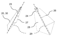
상기 메인 샤프트(4) 또는 하측 트랜스미션 기어 하우징(10)로부터 멀리 향하는 패들 샤프트(15)들의 하측 단부(21)에는, 패들(20)의 지지판(24)의 형태인 장착부와 안정화 튜브(23)에 대한 연결을 위한 추가적인 페더 키이(22)가 제공된다. 상기 추가적인 페더 키이(22)들은, 패들(20)들의 안정화 튜브(23)들이 신속히 조립될 수 있도록 하고, 또한 안정화 튜브(23) 각각과 패들 샤프트(15) 간의 연결이 패들(20)의 움직임에 의하여 헐거워지거나 변경되지 않도록 한다.At the
도 2 에 도시되어 있는 바와 같이, 하측 단부(21)에서 회전축(6)에 대한 샤프트 축(28)들의 제1 반경방향 거리는 메인 샤프트(4)를 대면하는 패들 샤프트(15)들의 상측 단부, 특히 베벨 기어(14)들에서 회전축(6)에 대한 샤프트 축(28)들의 제2 거리보다 더 크다.The first radial distance of the shaft axes 28 relative to the
추가적인 패더 키이(22)를 위한 노치(상세히 도시되지 않음)가 제공되어 있는 지지판(24)을 구비한 안정화 튜브(23)들은 패들 샤프트(15)들에 부착된다. 이와 같은 체결은, 예를 들어 잠금부, 볼트, 및 다른 기계적인 나사 연결 수단에 의해 이루어질 수도 있다.
상기 패들(20)의 안정화 튜브(23)들은 패들(20)을 위한 장착부의 역할을 하고, 패들(20) 각각의 안정성을 증진시키며, 또한 패들(20)의 패들 외측 표면(25)의 비틀림을 방지한다. 다시 말하면 이것은, 상기 안정화 튜브(23)들이 패들(20)들을 메인 샤프트(4)에 대하여 안정화시키고 서로에 대한 상대적 위치에 있도록 안정화시킴으로써, 위치 이탈이 방지되고 또한 아래에서 설명되는 바와 같이 각각의 각도 또는 각도 위치가 유지됨을 의미한다.The
상기 패들(20)들에는 패들(20)들의 유동성 개선과 보강을 위한 금속 브라켓(26)들이 제공된다. 또한, 상기 패들(20)들의 패들 에지(27)들은, 패들(20)들의 유동 거동을 더 향상시키기 위하여 접혀진다.The paddles (20) are provided with metal brackets (26) for fluidity improvement and reinforcement of the paddles (20). In addition, the paddle edges 27 of the paddles 20 are folded to further improve the flow behavior of the paddles 20.
상기 패들(20)들의 형상, 즉 외측 윤곽과 치수는, 교반될 유체의 양뿐만 아니라 유체 자체에 의하여 결정된다. 패들(20)을 위하여 다음과 같은 형상들이 사용된다: 원형, 장타원형(oval), 삼각형, 사다리꼴형, 다이아몬드형, 마름모형, 평행사변형, 정사각형, 직사각형, 사각형, 그리고 자연이나 동물로부터 얻어진 자연적 형상. 상기 패들(20)의 휘어짐 또는 변형이 패들(20)들의 안정성을 향상시키는데에 도움이 되고 그리고/또는 유체의 유동 거동에 긍정적인 영향을 준다면, 패들(20)이 휘어지거나 변형될 수도 있다. 도 1, 2, 4, 및 6 에서는, 상기 패들(20)이 평면 또는 판의 형상을 갖도록 설계되어 있다.The shape of the paddles 20, i.e., the outline contour and dimension, is determined by the fluid itself as well as the amount of fluid to be stirred. The following shapes are used for the paddle 20: circular, oval, triangular, trapezoidal, diamond shaped, rhombic, parallelogram, square, rectangular, square, and natural form . The paddle 20 may be bent or deformed if warping or deformation of the paddle 20 helps improve the stability of the paddles 20 and / or has a positive effect on the flow behavior of the fluid. 1, 2, 4, and 6, the paddles 20 are designed to have a flat or plate shape.
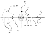
샤프트 축(28)을 구비한 패들 샤프트(15)들과, 축방향 연장선에서 동축의 패들 축(29)들을 구비한 패들(20)들은 메인 샤프트(4)에 대해 20° 내지 40°인 제1 각도(α)로 배치되는데, 이는 유체의 이상적인 유동 거동을 발생시키기 위한 것이다.
상기 패들(20)들이 패들 샤프트(15)들에 장착됨에 있어서는, 패들 표면(30)들이 도 6 에 도시된 바와 같이 서로에 대해 90°인 제2 각도(β)로 배치되도록 장착되는데, 이것은 유체의 이상적인 유동 거동을 발생시키기 위한 것이다. 이해를 돕기 위하여, 하나의 패들 표면(30)의 제1 단면 평면(E1)과 다른 패들 표면(30)의 제2 단면 평면(E2)이 도시되어 있다. 도면에서, 패들 표면(30)들이 서로에 대해 90°인 제2 각도(β)로 배치되어 있음을 알 수 있다.When the paddles 20 are mounted on the
상기 패들(20)들의 회전들, 즉 회전축(6)을 중심으로 하는 패들(20)들의 제1 회전 및 패들(20)들 각각의 패들 샤프트 축(28)을 중심으로 하는 패들(20) 각각의 제2 회전으로 인하여, 유체가 패들(20)들 각각의 앞으로 밀리거나 또는 변위된다. 이로 인하여 발생되는 움직임은 유체의 360° 전환을 보장하며, 이것은 유체의 성분들의 긴밀한 혼합과 유체의 균일성 극대화로 귀결된다.The rotation of the paddles 20, i.e. the first rotation of the paddles 20 about the axis of
이와 같은 유체의 움직임으로 인하여, 난류가 가능한 감소되고 전단력이 억제된다. 이것은 유체가 상당히 우수하게 혼합됨을 보장한다. 동시에, 상기 패들(20)들의 움직임 및 상기 유체에서 생성되는 움직임은, 유체의 움직임을 유지하기 위한 에너지가 종래의 교반기에서보다 현저히 적게 필요하게 되는 결과를 낳는다. 이와 같은 교반의 다른 장점은, 상기 유체 내의 임의의 고형 물질들이 패들(20)들 또는 연결부들, 즉 패들 샤프트(15)들, 지지판(24)들, 및 안정화 튜브(23)들 주위를 감싸지 않게 된다는 점이다.Due to this fluid movement, the turbulence is reduced as much as possible and the shear force is suppressed. This ensures that the fluid is mixed very well. At the same time, the motions of the paddles 20 and the motions generated in the fluid result in significantly less energy to sustain the movement of the fluid than in a conventional stirrer. Another advantage of such agitation is that any solid material in the fluid does not wrap around the paddles 20 or connections, i.e., the
도 3 및 도 5 는 보다 명확한 도시를 위한 것이다.Figures 3 and 5 are for a more clear view.
교반기(1)는 유체가 순환 또는 혼합되는 최대한 다양한 적용예들을 위하여 폭넓은 치수 및 구성을 갖도록 제작 및 제공된다. 이와 같은 적용예들에는 예를 들어 (가스 후드(gas hood)가 있거나 없는 바이오가스 플랜트, 거름 탱크, 우유 냉각기 등과 같은) 농업상 적용예, (에멀전 탱크, 연구소 내의 교반 기술 등과 같은) 산업상 적용예, (음료 및 과즙 생성기, 유제품, 맥주류 등과 같은) 음식산업 적용예, (하수 처리 플랜트, 상수 처리, 정체수(stagnant bodies of water) 처리 등과 같은) 지방자치단체 및 단체용 적용예, 기타 등등이 포함될 수 있다.The
바이오닉 교반기는 임의의 목재, 플라스틱, 탄소소재, 금속, 및 다른 현존하는 재료로 만들어질 수 있다. 연결부들, 특히 바이오닉 교반기의 구성부품들을 연결하는 패들 샤프트(15)들, 지지판(24)들, 및 안정화 튜브(23)들은 언제나 상기 교반기의 제작에 사용되는 재료의 유형 및 상태에 따라 정해진다. 따라서, 상기 연결부들은 나사 연결부, 접합 연결부, 플러그 연결부, 또는 리벳 연결부일 수 있다.The bionic agitator can be made of any wood, plastic, carbon material, metal, and other existing materials. The
본 발명의 바이오닉 교반기(1)는 가스 후드(gas hood)가 있거나 없는 바이오가스 플랜트에서의 교반, 농업에서의 거름의 교반, 지방자치단체, 단체, 및 도시의 하수 처리 및 상수 처리 시스템에서의 교반, 물처리 플랜트에서의 교반, 연구소에서의 교반, 음식 산업에서의 교반, 금속 산업에서의 교반, 화학 산업에서의 교반, 거주용 빌딩 및 단지에서의 공기 순환, 냉난방 설비가 있는 방의 순환, 원예 센터(garden centre)에서의 공기 순환, 상업 및 산업 지구에서의 공기 순환과 같은 다양한 적용 분야에서의 교반에서 사용될 수 있고, 교반기의 방위가 수평 자세 또는 수직 자세인 채로 사용될 수 있으며, 임의의 유형의 설비에서 사용될 수 있고, 사용되는 재료 및 치수의 면에서 임의의 실시형태로서 사용될 수 있으며, 또한 전술된 바와는 상이한 유형의 구동부, 기어 비율, 밀봉재, 및 연결부들을 구비하되 그 밖에는 전술된 바이오닉 교반기와 동일한 목적을 갖는 교반기로서 사용될 수 있다.The bionic agitator (1) of the present invention can be used for agitation in a biogas plant with or without a gas hood, agitation of agriculture in agriculture, agitation in municipal, community, and urban wastewater treatment and water treatment systems , Stirring in a water treatment plant, stirring in a laboratory, stirring in a food industry, stirring in a metal industry, stirring in a chemical industry, air circulation in a residential building and a complex, circulation of a room with heating and air conditioning, air circulation in a garden center, air circulation in commercial and industrial areas, and the orientation of the agitator can be used in a horizontal or vertical posture, and any type of equipment And may be used as any embodiment in terms of materials and dimensions used, and may also be of a different type of drive as that described above, But having the air ratio, sealing material, and the connection can be used as an agitator that outside has the same purpose as the above bionic stirrer.
Claims (10)
메인 샤프트(4)로부터 멀리 향하여 형성되어 있는 패들 샤프트(15)들의 하측 단부(21)에서의 회전축(6)에 대한 패들 샤프트 축(28)들의 제1 반경방향 거리는, 메인 샤프트(4)를 향하여 형성되어 있는 패들 샤프트(15)들의 상측 단부에서의 회전축(6)에 대한 패들 샤프트 축(28)들의 제2 반경방향 거리보다 더 큰 것을 특징으로 하는, 유체 혼합용 교반기.An agitator for mixing fluids having various viscosities, wherein the agitator (1) comprises a main shaft (4) having a rotating shaft (6) and paddles (20) connected to the main shaft Wherein each of the paddles (20) has a paddle shaft (15) having a paddle shaft shaft (28), the shaft axes (28) being connected to the rotating shaft The paddles 20 are arranged such that the paddle surfaces 30 are at a second angle? With respect to each other at a second angle?, And the stirrer 1 has a first angle? The paddles 20 perform a first rotation about the main shaft 4 and a second rotation about a respective paddle shaft 28,
The first radial distance of the paddle shaft axes 28 relative to the rotational axis 6 at the lower end 21 of the paddle shafts 15 which are formed away from the main shaft 4, Is greater than a second radial distance of the paddle shaft axes (28) with respect to the rotary shaft (6) at the upper end of the paddle shafts (15) formed.
상기 제1 회전은 메인 샤프트(4)와 패들(20)들 간의 토크-전달 연결부(non-rotatable connection; 10, 18)에 의하여 패들(20)들로 전달될 수 있고, 상기 제2 회전은 상기 메인 샤프트(4)와 패들(20)들 사이에 배치되어 있는 마찰 구동부(friction drive; 14, 16)에 의하여 상기 패들(20)들로 전달될 수 있는 것을 특징으로 하는, 유체 혼합용 교반기.The method according to claim 1,
The first rotation may be transmitted to the paddles 20 by a non-rotatable connection 10, 18 between the main shaft 4 and the paddles 20, Is capable of being transmitted to the paddles (20) by a friction drive (14, 16) disposed between the main shaft (4) and the paddles (20).
상기 토크-전달 연결부(10, 18)는 패들 샤프트(15)들을 회전가능하게 수용하는 제2 안내 튜브(second guide tube; 18)들에 의해 형성되고, 상기 패들 샤프트(15)들은 상기 메인 샤프트(4)와 토크-전달 방식으로 연결되어 있는 것을 특징으로 하는, 유체 혼합용 교반기.3. The method of claim 2,
The torque-transfer connection portions 10 and 18 are formed by second guide tubes 18 that rotatably receive the paddle shafts 15 and the paddle shafts 15 are connected to the main shaft 4) are connected to each other by a torque-transferring method.
상기 토크-전달 연결부(10, 18)의 형성을 위하여, 상기 메인 샤프트(4)와 토크-전달 방식으로 연결되어 있는 하우징(housing; 10)에 제2 안내 튜브(18)들이 토크-전달 방식으로 수용되어 있는 것을 특징으로 하는, 유체 혼합용 교반기.The method of claim 3,
In order to form the torque-transfer coupling portions 10 and 18, the second guide tubes 18 are connected to a housing 10 connected to the main shaft 4 in a torque-transmitting manner by a torque- Wherein the fluid is mixed with the fluid.
상기 마찰 구동부(14, 16)는 기어들(14, 16)을 포함하는 것을 특징으로 하는, 유체 혼합용 교반기.5. The method according to any one of claims 2 to 4,
Characterized in that the friction drive (14, 16) comprises gears (14, 16).
상기 기어들(14, 16)은 베벨 기어(bevel gear)들인 것을 특징으로 하는, 유체 혼합용 교반기.6. The method of claim 5,
Characterized in that the gears (14, 16) are bevel gears.
상기 마찰 구동부(14, 16)는 트랜스미션 기어 하우징(transmission gear housing; 10) 안에 수용된 것을 특징으로 하는, 유체 혼합용 교반기.7. The method according to any one of claims 2 to 6,
Characterized in that the friction drive (14, 16) is housed in a transmission gear housing (10).
상기 패들 샤프트(15)들은 장착부(mounting; 24)를 구비한 안정화 튜브(stabilising tube; 23)를 포함하고, 상기 안정화 튜브(23)에는 상기 패들 샤프트(15)의 추가적인 페더 키이(feather key; 22)를 위한 노치(notch)가 제공되어 있는 것을 특징으로 하는, 유체 혼합용 교반기.6. A method according to any one of the preceding claims,
The paddle shafts 15 include a stabilizing tube 23 having a mounting 24 and an additional feather key 22 of the paddle shaft 15 Characterized in that a notch for the fluid mixing is provided.
상기 패들 샤프트(15)들은 안정화 튜브(23)에 대한 연결을 위한 페더 키이를 포함하고, 상기 패들(20)로부터 멀리 향하는 단부에 상기 패들의 장착부(24)가 제공된 것을 특징으로 하는, 유체 혼합용 교반기.6. A method according to any one of the preceding claims,
Characterized in that the paddle shafts (15) comprise a feather key for connection to the stabilization tube (23) and a mounting portion (24) of the paddles is provided at an end facing away from the paddle agitator.
상기 패들 샤프트(15)들은 상기 제2 안내 튜브(18)들 안에 회전가능하게 수용되고, 상기 제2 안내 튜브(18)들은 보강 수단(reinforcing means; 19)에 의하여 하측 트랜스미션 기어(lower transmission gear; 5)의 트랜스미션 기어 하우징(10)과 연결되며, 상기 패들 샤프트(15)들은 복수의 베어링(bearing)에 의해 지지되고 또한 복수의 밀봉재에 의하여 상기 트랜스미션 기어 하우징(10)에 대해 밀봉되는 것을 특징으로 하는, 유체 혼합용 교반기.6. A method according to any one of the preceding claims,
The paddle shafts 15 are rotatably received in the second guide tubes 18 and the second guide tubes 18 are reinforced by means of reinforcing means 19 to form a lower transmission gear. And the paddle shafts 15 are supported by a plurality of bearings and are sealed to the transmission gear housing 10 by a plurality of sealing materials Wherein the fluid mixing apparatus comprises:
Applications Claiming Priority (3)
| Application Number | Priority Date | Filing Date | Title |
|---|---|---|---|
| DE102013018725.7 | 2013-11-08 | ||
| DE201310018725 DE102013018725A1 (en) | 2013-11-08 | 2013-11-08 | Bionic agitator |
| PCT/EP2014/073689 WO2015067599A1 (en) | 2013-11-08 | 2014-11-04 | Agitator for mixing fluids |
Publications (1)
| Publication Number | Publication Date |
|---|---|
| KR20160081923A true KR20160081923A (en) | 2016-07-08 |
Family
ID=51846679
Family Applications (1)
| Application Number | Title | Priority Date | Filing Date |
|---|---|---|---|
| KR1020167012848A KR20160081923A (en) | 2013-11-08 | 2014-11-04 | Agitator for mixing fluids |
Country Status (16)
| Country | Link |
|---|---|
| US (1) | US20170252711A1 (en) |
| EP (1) | EP3065852B1 (en) |
| JP (1) | JP2016534875A (en) |
| KR (1) | KR20160081923A (en) |
| CN (1) | CN105792920A (en) |
| AU (1) | AU2014345725B2 (en) |
| CA (1) | CA2929195A1 (en) |
| DE (1) | DE102013018725A1 (en) |
| DK (1) | DK3065852T3 (en) |
| ES (1) | ES2682324T3 (en) |
| HU (1) | HUE038661T2 (en) |
| MX (1) | MX2016005779A (en) |
| PL (1) | PL3065852T3 (en) |
| RU (1) | RU2674127C2 (en) |
| WO (1) | WO2015067599A1 (en) |
| ZA (1) | ZA201602929B (en) |
Families Citing this family (4)
| Publication number | Priority date | Publication date | Assignee | Title |
|---|---|---|---|---|
| CN107551851A (en) * | 2017-11-03 | 2018-01-09 | 王丽 | A kind of agitating device for ink equipment manufacture |
| CN110339758B (en) * | 2019-08-14 | 2021-10-15 | 义乌工商职业技术学院 | Cleaning fluid mixing equipment and cleaning machine |
| CN112221371A (en) * | 2020-10-28 | 2021-01-15 | 吉林大学 | Bionic viscosity-reducing organic fertilizer stirring blade and stirring roller |
| CN116099480B (en) * | 2023-04-11 | 2023-06-09 | 利安隆(天津)制药有限公司 | Reaction kettle and water washing system with same |
Family Cites Families (23)
| Publication number | Priority date | Publication date | Assignee | Title |
|---|---|---|---|---|
| US3126196A (en) * | 1964-03-24 | Staeger | ||
| DE154115C (en) * | 1901-10-06 | 1904-10-10 | Karl Postranecky | PLANETARY STIRRER WITH INCLINED STIRRER |
| DE1107648B (en) * | 1959-10-06 | 1961-05-31 | Conrad Sigg | Device for mixing and kneading substances in a mixing container with a circular cross-section that widens towards the top |
| DE1214651B (en) * | 1963-06-08 | 1966-04-21 | Alfred Paul K G | Stirring device with drive of the stirring tools through a planetary gear |
| SU1238783A1 (en) * | 1983-07-26 | 1986-06-23 | Московский Ордена Трудового Красного Знамени Институт Химического Машиностроения | Mixer for highly viscous materials |
| US4697929A (en) * | 1986-10-28 | 1987-10-06 | Charles Ross & Son Company | Planetary mixers |
| DE3824885A1 (en) * | 1988-07-22 | 1990-01-25 | Janke & Kunkel Kg | STIRRING AND / OR KNEADING MACHINE |
| SU1676813A1 (en) * | 1989-01-19 | 1991-09-15 | Омский политехнический институт | Mixer |
| US5102229A (en) | 1990-06-15 | 1992-04-07 | Sumitomo Heavy Industries, Ltd | Agitator |
| SU1813544A1 (en) * | 1990-08-13 | 1993-05-07 | Nii Polimernykh Materialov | Vertical planetary mixer |
| EP0641595A1 (en) * | 1993-09-08 | 1995-03-08 | DE DIETRICH & Cie, Société Anonyme dite | Separable enamel agitator for chemical reactors |
| DE29511227U1 (en) | 1995-07-11 | 1995-09-14 | Winkler Gmbh & Co Kg Baeckerei | Knife star dough dividing and rounding device |
| DE19756485C2 (en) | 1997-12-18 | 1999-12-23 | Xaver Lipp | Digester with agitator and method for operating an agitator in a digester |
| JP2004510574A (en) * | 2000-10-06 | 2004-04-08 | エイチ.ジェイ.ヘインズ カンパニー | Agitation in the filling bowl |
| AU2003209910A1 (en) * | 2002-04-17 | 2003-10-27 | Hermann Dettwiler | Movement conversion device |
| JP2004041903A (en) * | 2002-07-11 | 2004-02-12 | Inoue Mfg Inc | Planetary mixer |
| JP2005262094A (en) * | 2004-03-18 | 2005-09-29 | Mitsui Eng & Shipbuild Co Ltd | Rotation and revolution type agitator |
| DE202004005331U1 (en) | 2004-04-03 | 2004-06-03 | Eckart, Gerhard | Biomass- or sludge stirrer used in digester tanks of waste water treatment plant, comprises removable tube carrying motor, transmission system and agitators |
| DE202008015990U1 (en) | 2008-12-07 | 2009-02-19 | Suma Sondermaschinen Gmbh | agitator |
| DE102010002461A1 (en) | 2010-03-01 | 2011-09-01 | Roland Lipp | Container i.e. digestion vessel, for use in e.g. agricultural biogas plant, for transforming organic substances, has agitator channel whose drive-lateral opening is arranged above half standard filling height of container |
| DE202011107055U1 (en) | 2011-10-21 | 2013-01-25 | Thomas Kainz | Agitator for a fermenter tank, fermenter tank with such a stirrer and biogas plant |
| DE202011052408U1 (en) | 2011-12-21 | 2012-03-22 | Skm Stahl- Und Maschinenbau Gmbh | agitator |
| CN202387404U (en) * | 2012-01-04 | 2012-08-22 | 保定嘉利食品机械有限公司 | Tilting-type planetary agitating pan |
-
2013
- 2013-11-08 DE DE201310018725 patent/DE102013018725A1/en not_active Withdrawn
-
2014
- 2014-11-04 ES ES14793142.2T patent/ES2682324T3/en active Active
- 2014-11-04 CN CN201480060898.XA patent/CN105792920A/en active Pending
- 2014-11-04 MX MX2016005779A patent/MX2016005779A/en unknown
- 2014-11-04 JP JP2016551020A patent/JP2016534875A/en active Pending
- 2014-11-04 PL PL14793142T patent/PL3065852T3/en unknown
- 2014-11-04 EP EP14793142.2A patent/EP3065852B1/en active Active
- 2014-11-04 DK DK14793142.2T patent/DK3065852T3/en active
- 2014-11-04 HU HUE14793142A patent/HUE038661T2/en unknown
- 2014-11-04 WO PCT/EP2014/073689 patent/WO2015067599A1/en active Application Filing
- 2014-11-04 CA CA2929195A patent/CA2929195A1/en not_active Abandoned
- 2014-11-04 AU AU2014345725A patent/AU2014345725B2/en not_active Ceased
- 2014-11-04 KR KR1020167012848A patent/KR20160081923A/en not_active Application Discontinuation
- 2014-11-04 RU RU2016118797A patent/RU2674127C2/en not_active IP Right Cessation
-
2016
- 2016-04-29 ZA ZA2016/02929A patent/ZA201602929B/en unknown
- 2016-05-03 US US15/145,693 patent/US20170252711A1/en not_active Abandoned
Also Published As
| Publication number | Publication date |
|---|---|
| WO2015067599A1 (en) | 2015-05-14 |
| JP2016534875A (en) | 2016-11-10 |
| CN105792920A (en) | 2016-07-20 |
| PL3065852T3 (en) | 2018-11-30 |
| DK3065852T3 (en) | 2018-08-06 |
| CA2929195A1 (en) | 2015-05-14 |
| RU2016118797A3 (en) | 2018-06-08 |
| EP3065852A1 (en) | 2016-09-14 |
| ZA201602929B (en) | 2017-02-22 |
| US20170252711A1 (en) | 2017-09-07 |
| HUE038661T2 (en) | 2018-11-28 |
| MX2016005779A (en) | 2016-12-09 |
| AU2014345725A1 (en) | 2016-06-02 |
| ES2682324T3 (en) | 2018-09-20 |
| RU2674127C2 (en) | 2018-12-04 |
| RU2016118797A (en) | 2017-12-13 |
| DE102013018725A1 (en) | 2015-05-13 |
| EP3065852B1 (en) | 2018-05-02 |
| AU2014345725B2 (en) | 2018-11-15 |
Similar Documents
| Publication | Publication Date | Title |
|---|---|---|
| CN102847478B (en) | Magnetic mixing device | |
| KR101566240B1 (en) | Aeration impeller and agitator for water treatment having the same | |
| KR20160081923A (en) | Agitator for mixing fluids | |
| CN204447990U (en) | Agitator | |
| CN202909674U (en) | Magnetic stirring device | |
| CN110280168B (en) | Stirrer and working method thereof | |
| CN102491545A (en) | Double-curved-surface stirring aerator | |
| CN204429135U (en) | A kind of culture medium of edible fungus special agitating apparatus | |
| WO2013147620A1 (en) | Improvements in and relating to agitator systems | |
| CN201279445Y (en) | Eddy powder mixer | |
| CN207507371U (en) | Insulating brick for construction raw material agitation mixer | |
| CN105727821B (en) | A kind of mixing plant and its blender | |
| US20220023810A1 (en) | Magnetically-coupled liquid mixer | |
| CN206510242U (en) | Centrifugal kneader body assembly | |
| CN212283645U (en) | Be used for anticorrosive terrace unsaturated resin production mixing arrangement | |
| CN216171782U (en) | Two-way agitator with second grade rotary mechanism | |
| CN214973153U (en) | Transmission assembly for propulsion type axial flow stirring device | |
| CN209576440U (en) | It is a kind of to be used to prepare super-hydrophobic blending tank | |
| CN220546857U (en) | Double-shaft mixer | |
| CN207273553U (en) | A kind of asphalt double horizontal axle agitator | |
| CN220162896U (en) | Batching mechanism for plastic pipe production | |
| CN219209627U (en) | Stirring device for aqueous acrylic resin | |
| CN218131124U (en) | Multi-shaft stirring type aeration paddle and fermentation tank | |
| CN208629707U (en) | Agitating device is used in a kind of production of fluororesin gasket | |
| CN213610980U (en) | Solid-liquid material mixing and stirring device for processing olive health food |
Legal Events
| Date | Code | Title | Description |
|---|---|---|---|
| WITN | Application deemed withdrawn, e.g. because no request for examination was filed or no examination fee was paid |