KR20160077471A - Speed Sensing System of Multi- Road Lane and Speed Sensing Method of Multi-Lane - Google Patents
Speed Sensing System of Multi- Road Lane and Speed Sensing Method of Multi-Lane Download PDFInfo
- Publication number
- KR20160077471A KR20160077471A KR1020140187109A KR20140187109A KR20160077471A KR 20160077471 A KR20160077471 A KR 20160077471A KR 1020140187109 A KR1020140187109 A KR 1020140187109A KR 20140187109 A KR20140187109 A KR 20140187109A KR 20160077471 A KR20160077471 A KR 20160077471A
- Authority
- KR
- South Korea
- Prior art keywords
- vehicle
- lane
- radar
- speed
- signal
- Prior art date
Links
Images


Classifications
-
- G—PHYSICS
- G01—MEASURING; TESTING
- G01S—RADIO DIRECTION-FINDING; RADIO NAVIGATION; DETERMINING DISTANCE OR VELOCITY BY USE OF RADIO WAVES; LOCATING OR PRESENCE-DETECTING BY USE OF THE REFLECTION OR RERADIATION OF RADIO WAVES; ANALOGOUS ARRANGEMENTS USING OTHER WAVES
- G01S7/00—Details of systems according to groups G01S13/00, G01S15/00, G01S17/00
- G01S7/02—Details of systems according to groups G01S13/00, G01S15/00, G01S17/00 of systems according to group G01S13/00
- G01S7/021—Auxiliary means for detecting or identifying radar signals or the like, e.g. radar jamming signals
- G01S7/022—Road traffic radar detectors
-
- G—PHYSICS
- G01—MEASURING; TESTING
- G01S—RADIO DIRECTION-FINDING; RADIO NAVIGATION; DETERMINING DISTANCE OR VELOCITY BY USE OF RADIO WAVES; LOCATING OR PRESENCE-DETECTING BY USE OF THE REFLECTION OR RERADIATION OF RADIO WAVES; ANALOGOUS ARRANGEMENTS USING OTHER WAVES
- G01S13/00—Systems using the reflection or reradiation of radio waves, e.g. radar systems; Analogous systems using reflection or reradiation of waves whose nature or wavelength is irrelevant or unspecified
- G01S13/02—Systems using reflection of radio waves, e.g. primary radar systems; Analogous systems
- G01S13/06—Systems determining position data of a target
- G01S13/08—Systems for measuring distance only
- G01S13/10—Systems for measuring distance only using transmission of interrupted, pulse modulated waves
- G01S13/26—Systems for measuring distance only using transmission of interrupted, pulse modulated waves wherein the transmitted pulses use a frequency- or phase-modulated carrier wave
- G01S13/28—Systems for measuring distance only using transmission of interrupted, pulse modulated waves wherein the transmitted pulses use a frequency- or phase-modulated carrier wave with time compression of received pulses
- G01S13/282—Systems for measuring distance only using transmission of interrupted, pulse modulated waves wherein the transmitted pulses use a frequency- or phase-modulated carrier wave with time compression of received pulses using a frequency modulated carrier wave
-
- G—PHYSICS
- G01—MEASURING; TESTING
- G01S—RADIO DIRECTION-FINDING; RADIO NAVIGATION; DETERMINING DISTANCE OR VELOCITY BY USE OF RADIO WAVES; LOCATING OR PRESENCE-DETECTING BY USE OF THE REFLECTION OR RERADIATION OF RADIO WAVES; ANALOGOUS ARRANGEMENTS USING OTHER WAVES
- G01S13/00—Systems using the reflection or reradiation of radio waves, e.g. radar systems; Analogous systems using reflection or reradiation of waves whose nature or wavelength is irrelevant or unspecified
- G01S13/02—Systems using reflection of radio waves, e.g. primary radar systems; Analogous systems
- G01S13/50—Systems of measurement based on relative movement of target
- G01S13/58—Velocity or trajectory determination systems; Sense-of-movement determination systems
- G01S13/581—Velocity or trajectory determination systems; Sense-of-movement determination systems using transmission of interrupted pulse modulated waves and based upon the Doppler effect resulting from movement of targets
-
- G—PHYSICS
- G08—SIGNALLING
- G08G—TRAFFIC CONTROL SYSTEMS
- G08G1/00—Traffic control systems for road vehicles
- G08G1/01—Detecting movement of traffic to be counted or controlled
- G08G1/052—Detecting movement of traffic to be counted or controlled with provision for determining speed or overspeed
Abstract
Description
본 발명은 한대의 FMCW( Frequency Modulation Continuous Wave) 레이더를 이용하여 복수의 차선에 대한 차량 속도를 검출하는 것에 관한 것이다. 일반적으로 현재는 차선별로 루프 감지기를 설치하거나 영상 감지기를 설치하여 하나의 차선을 주행하는 차량에 대하여 각 차선별로 속도를 검출하도록 구성되어 있는 것이다. 또한 도플러 주파수를 측정하여 차선을 주행하는 차량에 대한 차량 속도를 측정하는 방법에 공지되어 있으나 이는 측정된 속도가 부정확한 문제점이 있는 것이다.
The present invention relates to detecting a vehicle speed for a plurality of lanes using a single FMCW (Frequency Modulation Continuous Wave) radar. Generally, at present, a loop detector is installed for each lane or an image sensor is installed to detect a speed of each lane for a vehicle traveling in one lane. It is also known to measure vehicle speed with respect to a vehicle traveling in a lane by measuring the Doppler frequency, but the measured speed is inaccurate.
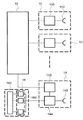
본 발명과 관련된 종래의 기술은 대한민국 공개특허 공보 제10-2014-0014159호(2014. 02. 05. 공개)에 개시되어 있는 것이다. 도 1은 상기 종래의 다중 송신기와 비트 주파수 멀티플렉서를 구비한 에프엠씨더블류(FMCW) 레이더 시스템 구성도이다. 상기도 1에서 종래의 FMCW 레이더 시스템은 복수의 송신기(10), 스윕 동기회로(12), 수신기(14) 및 신호 처리회로(16)로 구성된 것을 나타내고 있는 것이다. 상기에서 각각의 송신기(10)는 제어 가능한 발진기(100)와 제어 가능한 발진기(100)에 연결된 입력을 가진 송신기 안테나(102)로 구성되어 있다. 또한, 송신기(10)의 제어 가능한 발진기(100)는 코먼 클럭 회로(미도시)(common clock circuit)의 제어 아래 동작하는 디지털 발전기 일 수 있고, 클럭 신호(clock signal)로 정의된 일련의 타임 포인트에 대해 연속적인 타임 디스크리트 디지털 오실레이터 신호 값을 결정하고, 이값을 아날로그 신호로 변환할 수 있는 오실레이트이다. 또한, 다른 송신기(10)의 송신기 안테나는 공간 어레이로 배열되고 스윕 동기회로(12)는 송신기(10)의 제어 가능한 발진기(100)의 입력을 제어하기 위하여 결합된 복수의 출력을 가지고 있는 것이다. 또한, 수신기(14)는 안테나(140), 제어 가능한 국부 발진기(142) 및 믹서(144)로 구성되어 있으며 제어 가능한 국부 발진기(142)는 송신기(10)의 제어 가능한 발진기(100)와 동일한 클럭회로(미도시)의 제어 하에 동작하는 디지털오실레이터일 수 있는 것이다. 또한, 믹서(144)는 안테나(140)와 국부 발진기(142)에 결합된 신호 입력을 가지며 제어 가능한 국부 발진기(142)는 스윕 동기회로(12)의 출력과 결합된 제어 입력을 가진다. 또한, 믹서(144)는 신호 처리회로(16)와 결합된 출력을 가지며 신호 처리회로(16)는 복수의 대역필터모듈(band filter module)(예를 들어, 아날로그 또는 디지털 필터모듈)과 조합모듈(162)로 구현될 수 있는 필터 뱅크(160)로 구성되어 있는 것이다. 또한, 필터 뱅크(160)는 수신기(14)의 출력과 연결된 입력(예를 들면 필터 뱅크에서 대역필터모듈은 입력을 가진다)과 조합모듈(162)에 연결된 출력을 가지며 스윕 동기회로(12)는 서로에 대해 상호 타임오프셋에서 같은 주파수 스윕을 수행하는 송신기(10)의 제어 가능한 발진기(100)를 제어하는 것이고, 상기 스윕 동기회로(12)는 유사한 스윕을 수행하는 국부발진기(142)를 제어하는 것이다.
The prior art related to the present invention is disclosed in Korean Patent Laid-Open Publication No. 10-2014-0014159 (published on April 25, 2015). BRIEF DESCRIPTION OF THE DRAWINGS FIG. 1 is a block diagram of an FMCW radar system including a conventional multi-transmitter and a bit-frequency multiplexer. 1, the conventional FMCW radar system includes a plurality of
상기와 같은 종래의 멀티플렉서를 구비한 에프엠씨더블류(FMCW) 레이더 시스템은 물체를 검출할 수 있으나 이를 이용하여 복수 차선의 차량 속도를 검출할 수 없는 문제점이 있는 것이다. 또한 상기와 같은 종래의 기술은 복수의 송신기를 구비하고 있어 시스템 구축에 비용이 과다 소요되는 문제점이 있는 것이다. 따라서 본 발명의 목적은 FMCW 레이더를 이용하여 복수 차선을 주행하는 차량의 속도를 각각 검출하기 위한 것이다. 또한 본 발명의 다른 목적은 하나의 FMCW 레이더를 이용하여 다수 차선을 주행하는 차량의 속도를 검출하기 위한 것이다.
The conventional FMCW radar system including the conventional multiplexer can detect an object but can not detect a vehicle speed of a plurality of lanes using the detected object. In addition, since the conventional technology as described above includes a plurality of transmitters, there is a problem that the system construction cost is excessively high. Accordingly, an object of the present invention is to detect the speed of a vehicle traveling in a plurality of lanes using an FMCW radar, respectively. Another object of the present invention is to detect the speed of a vehicle traveling in a plurality of lanes using one FMCW radar.
상기와 같은 목적을 가진 본 발명 복수 차선의 속도 검출 시스템은 DAC로부터 제어 신호를 수신하여 레이더 신호를 출력하고 도로에서 주행중인 차량에 반사되어 수신되는 레이더 신호를 증폭부로 전송하는 레이더부와, MCU의 제어 신호를 수신하여 아날로그 신호로 변환하여 레이더부로 전송하는 DAC와, 상기 레이더부에서 수신되는 반사 레이더 신호를 증폭하는 증폭부와, 상기 증폭부에서 증폭된 반사 레이더 신호를 디지털 신호로 변환하여 MCU로 전송하는 ADC와, 레이더 신호를 차량 쪽으로 전송하도록 제어 신호를 DAC로 전송하고 상기 ADC로부터 반사 레이더 신호를 수신하여 차량 검출 알고리즘에 의하여 주행 차량을 검출하고 차량과의 탐지거리, 탐지시간 및 차량과의 거리에 따른 차선을 판별하고 각 차선을 주행하는 차량의 속도를 산정하고 각 차선을 주행하는 각 차량 속도 정보를 메모리에 저장하고 각 차선별 각 차량 속도 정보를 서버로 전송하도록 제어하는 MCU와, MCU의 제어에 의하여 각 차선별 각 차량 속도 정보를 서버로 송신하기 위한 송수신부와, 상기 MCU로부터 송수신부를 거쳐서 수신된 차선별 각 차량 속도 값을 표시부를 통하여 표출하는 서버로 구성된 것을 특징으로 하는 것이다. According to another aspect of the present invention, there is provided a speed detection system for a multi-lane vehicle including a radar unit for receiving a control signal from a DAC and outputting a radar signal, a radar unit for transmitting a radar signal received from a vehicle, A DAC for receiving a control signal and converting the analog signal into an analog signal and transmitting the signal to a radar unit; an amplifying unit for amplifying a reflected radar signal received by the radar unit; A transmitting ADC for transmitting a control signal to the DAC to transmit the radar signal to the vehicle and receiving a reflected radar signal from the ADC to detect the traveling vehicle by the vehicle detection algorithm and detecting the distance to the vehicle, The lane along the distance is determined, the speed of the vehicle traveling in each lane is calculated, And a controller for controlling the MCU to transmit the vehicle speed information to the server by the control of the MCU, wherein the vehicle speed information is stored in a memory, And a server for displaying the vehicle speed values of the respective cars received from the MCU through the transmission / reception unit through a display unit.
상기와 같이 구성된 본 발명 복수 차선의 속도 검출 시스템 및 이를 이용한 복수 차선의 속도 검출 방법은 하나의 레이더부를 이용하여 복수의 차선을 주행하는 각 차량의 속도를 산정할 수 있는 효과가 있는 것이다. 또한 본 발명의 복수 차선의 속도 검출 시스템 및 이를 이용한 복수 차선의 속도 검출 방법은 시스템 구성이 단순하여 설치 비용이 저렴하고 유지 관리 비용이 저렴한 효과가 있는 것이다.
The speed detection system of the present invention constructed as described above and the speed detection method of a plurality of lanes using the same have the effect of calculating the speed of each vehicle traveling in a plurality of lanes by using one radar unit. Further, the multi-lane speed detection system of the present invention and the multi-lane speed detection method using the same have the simple system configuration, low installation cost, and low maintenance cost.
도 1은 종래의 다중 송신기와 비트 주파수 멀티플렉서를 구비한 에프엠씨더블류(FMCW) 레이더 시스템 구성도,
도 2는 본 발명 복수 차선의 차량 속도 검출 시스템 전체 구성도,
도 3은 본 발명 복수 차선의 차량 속도 검출 시스템이 적용되는 레이더부 제1실시 예 설치 예시도,
도 4는 본 발명 복수 차선의 차량 속도 검출 시스템이 적용되는 레이더부 제2실시 예 설치 예시도,
도 5는 본 발명에 적용되는 것으로 차량에 레이더 신호를 전송하는 상태도,
도 6은 상기도 5로부터 생성되는 비트 주파수 그래프,
도 7은 상기도 6으로부터 생성되는 상승 비트 주파수와 하강 비트 주파수 그래프,
도 8은 본 발명 복수 차선의 차량 속도 검출 방법에 대한 제어 흐름도,
도 9는 도 8의 C 후단에 이어지는 흐름도,
도 10은 탐지 거리의 보정을 나타내는 그래프이다.FIG. 1 is a block diagram of an FMCW radar system including a conventional multi-transmitter and a bit-frequency multiplexer,
Fig. 2 is an overall configuration diagram of the vehicle speed detection system of the present invention,
FIG. 3 is a diagram showing an example of installation of a radar unit according to a first embodiment of the present invention,
Fig. 4 is a diagram showing an example of installing a radar unit according to a second embodiment of the present invention,
FIG. 5 is a state diagram of a radar signal transmission system according to the present invention,
FIG. 6 is a graph showing the bit frequency graph generated from FIG. 5,
FIG. 7 is a graph showing the rising bit frequency and the falling bit frequency generated from the FIG. 6,
Fig. 8 is a control flowchart for the vehicle speed detection method of the present invention,
Fig. 9 is a flow chart following the end of C in Fig. 8,
10 is a graph showing the correction of the detection distance.
상기와 같은 목적을 가진 본 발명 복수 차선의 차량 속도 검출 시스템 및 이를 이용한 복수 차선의 차량 속도 검출 방법을 도 2 내지 도 10을 참고로 하여 설명하면 다음과 같다.
The multi-lane vehicle speed detecting system and the multi-lane vehicle speed detecting method using the same will now be described with reference to FIGS. 2 to 10. FIG.
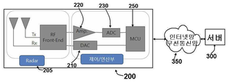
도 2는 본 발명 복수 차선의 차량 속도 검출 시스템 전체 구성도이다. 상기도 2에서 본 발명 복수 차선의 차량 속도 검출 시스템은 DAC로부터 제어 신호를 수신하여 레이더 신호를 출력하고 도로에서 주행중인 차량에 반사되어 수신되는 레이더 신호를 증폭부로 전송하는 레이더(205)와, MCU의 제어 신호를 수신하여 아날로그 신호로 변환하여 레이더(205)로 전송하는 DAC(Digital Analog Converter, 210)와, 상기 레이더에서 수신되는 반사 레이더 신호를 증폭하는 증폭부(220)와, 상기 증폭부에서 증폭된 반사 레이더 신호를 디지털 신호로 변환하여 MCU로 전송하는 ADC(Analog Digital Converter, 230)와, 레이더 신호를 차량 쪽으로 전송하도록 제어 신호를 DAC로 전송하고 상기 ADC로부터 반사 레이더 신호를 수신하여 푸리에 변환하고 MTI(Moving Target Indicator) 및 차량 검출 알고리즘에 의하여 주행 차량을 검출하고 차량과의 탐지 거리, 탐지 시간 및 차량과의 거리에 따른 차선을 판별하고 각 차선을 주행하는 차량의 속도를 산정하고 각 차선을 주행하는 각 차량 속도 정보를 메모리에 저장하고, 각 차선별 각 차량 속도 정보를 서버로 전송하도록 제어하는 MCU(250)와, MCU의 제어에 의하여 각 차선별 차량 속도 정보를 서버로 송신하기 위한 송수신부(260)와, 상기 MCU로부터 송수신부를 거쳐서 수신된 차선별 각 차량 속도 값을 저장하고 표시부를 통하여 표출하는 서버(300) 및 레이더부(200)와 서버를 연결하는 인터넷망 또는 무선 통신망(350)으로 구성된 것을 특징으로 하는 것이다.
Fig. 2 is an overall configuration view of the vehicle speed detection system of the present invention. 2, the multi-lane vehicle speed detecting system includes a
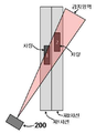
도 3은 본 발명 복수 차선의 차량 속도 검출 시스템이 적용되는 레이더부 제1실시 예 설치 예시도 이다. 상기도 3에서 본 발명 복수 차선의 차량 속도 검출 시스템이 적용되는 레이더부(200) 제1실시 예는 복수의 n차선이 존재하고 복수의 n차선을 주행하는 차량(400)이 존재하는 경우 각 차선별 주행하는 차량의 속도를 산정하기 위하여 레이더부의 설치 상태 도를 나타내는 것이다. 상기도 3에서 도플러 효과를 이용하여 각 차선을 판별하기 위하여는 레이더부에서 송출하는 레이더 신호가 차량에 반사되어 레이더부로 수신될 수 있도록 차선에 일정각도(θ) 경사지게 설치하는 것임을 예시로 보여주고 있는 것이다. 만약 레이더부가 차선과 직각으로 설치되어 레이더 신호를 차량으로 송신하는 경우 내측 차선을 주행하는 차량은 탐지될 수 있으나 외측 차선을 주행하는 차량은 내측 차선의 차량에 의하여 방해되어 차량 검출에 오류가 발생할 수 있는 것이다.
3 is a diagram illustrating an example of installation of a radar unit according to a first embodiment of the present invention. 3, the
도 4는 본 발명 복수 차선의 차량 속도 검출 시스템이 적용되는 레이더부 제2실시 예 설치 예시도 이다. 상기도 4에서 본 발명 복수 차선의 차량 속도 검출 시스템이 적용되는 레이더부(200) 제2실시 예는 1차선과 2차선으로 구성되고 도로 일측에 지주를 세우고 레이더부를 지주의 상단에 설치되는 것으로서 내측 차선인 1차선과 외측 차선인 2차선을 각각 주행하는 차량에 대하여 레이더 신호를 송신하여 각 차량에 반사되는 레이더 신호를 수신하는데 아무 문제가 없도록 설치되는 경우이다. 상기에서 2차선의 경우에 대하여 예를 들었으나 3차선 또는 n차선으로 확대할 수 있는 것이다.
4 is a diagram illustrating an example of the installation of a radar unit according to a second embodiment of the present invention in which a vehicle speed detection system for a plurality of lanes is applied. 4, the
도 5는 본 발명에 적용되는 것으로 차량에 레이더 신호를 전송하는 상태도 이다. 상기도 5에서 레이더부(200)에서 송신되는 레이더 신호를 각 차선을 주행하는 차량(400)으로 전송하고 상기 차량에 반사되어 레이더부로 수신될 수 있는 것으로서 레이더부에서 전송되는 레이더 신호의 주파수가 f이면 차량에 반사되어 레이더부로 수신되는 주파수는 f + fD가 되는 것임을 나타내고 있는 것이다. 상기에서 fD는 도플러 주파수이다.
5 is a state diagram of a radar signal transmitted to a vehicle as applied to the present invention. 5, the radar signal transmitted from the
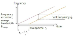
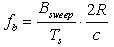
도 6은 상기도 5로부터 생성되는 비트 주파수 그래프이다. 상기도 5에서 레이더부에서 차량까지의 거리가 R이고, 레이더 신호의 스윕 대역폭(Sweep Bandwidth), Bsweep 이고, 레이더 신호의 주기가 Ts이면 레이더부에서 차량까지의 차량 탐지 시간 td= 2R/c 이고, td/Ts= fb/Bsweep 및 R = cTsfb /2Bsweep로 나타낼 수 있는 것이다. 또한 도플러 주파수는 fD= 2Vr/λ로 나타낼 수 있는 것이다. 여기에서 c는 빛의 속도이고, Vr 은 차량의 속도이고, λ는 레이더 신호의 파장을 나타내고 있는 것이다. 차량까지의 탐지 시간이 측정되면 레이더부에서 차량까지의 거리 R을 구할 수 있으며 비트 주파수 fb를 구할 수 있는 것이다.
FIG. 6 is a graph of the bit frequency generated from FIG. 5, the distance from the radar unit to the vehicle is R, and the sweep bandwidth of the radar signal (Sweep Bandwidth), B sweep If the period of the radar signal is T s , the vehicle detection time from the radar unit to the vehicle t d = 2R / c, t d / T s = f b / B sweep And R = is which may be represented by cT s f b / 2B sweep. The Doppler frequency can also be expressed as f D = 2V r / λ. Where c is the speed of light and V r Is the speed of the vehicle, and [lambda] is the wavelength of the radar signal. When the detection time to the vehicle is measured, the distance R from the radar unit to the vehicle can be obtained and the bit frequency f b can be obtained.
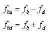
도 7은 상기도 6으로부터 생성되는 상승 비트 주파수와 하강 비트 주파수 그래프이다. 상기도 7에서 비트 주파수는 식 (1)로 표시할 수 있는 것이다.FIG. 7 is a graph of the rising bit frequency and the falling bit frequency generated from FIG. In FIG. 7, the bit frequency can be expressed by Equation (1).
또한, 도플러 주파수(상기 fD 와 동일함)는 다음 식(2)로 나타낼 수 있는 것이다. Further, the Doppler frequency (f D ) Can be expressed by the following equation (2).

따라서 상기도 7에서 비트 주파수를 상승 시 비트 주파수 및 하강 시 비트 주파수로 분리하면 다음 식(3)과 같이 나타낼 수 있는 것이다.Therefore, in FIG. 7, when the bit frequency is divided into the bit frequency and the falling bit frequency, the following equation (3) can be obtained.

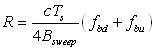
상기 식(1), 식(2) 및 식(3)으로부터 레이더부에서 차량까지의 거리 및 차량의 속도는 아래 식(4)로 나타낼 수 있는 것이다.From the above equations (1), (2) and (3), the distance from the radar unit to the vehicle and the speed of the vehicle can be expressed by the following equation (4).

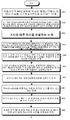
도 8은 본 발명 복수 차선의 차량 속도 검출 방법에 대한 제어 흐름도이고 도 9는 도 8의 C 후단에 이어지는 흐름도이다. 상기도 8 및 도 9에서 본 발명 복수 차선의 차량 속도 검출 방법은 레이더부의 MCU 제어에 의하여 레이더부에서 레이더신호를 복수의 n 차선으로 송신하는 단계(S11)와, 도로에서 복수의 n 차선에 차량이 주행하여 주행하는 차량으로부터 반사하는 레이더 신호를 각각 수신하여 차량까지의 제1탐지 거리 내지 제n탐지 거리 및 제1탐지 시간 내지 제n탐지 시간을 산정하는 단계(S12)와, 탐지 거리를 기초로 하여 거리에 따른 각 차선을 판별하는 단계(S13)와, 기 주어진 레이더 신호 스윕 대역폭, 레이더 신호 주파수, 레이더 신호 주기, 파장, 빛의 속도와 상기 제1탐지 거리 내지 제n탐지거리 및 제1탐지 시간 내지 제n탐지 시간을 이용하여 각 차선을 주행하는 각 차량에 대하여 비트 주파수와 도플러 주파수를 산정하는 단계(S14)와, 상승 시 비트 주파수 및 하강 시 비트 주파수를 상기 각 차선을 주행하는 차량에 대한 각 비트 주파수와 각 도플러 주파수의 중첩식으로 산정하는 단계(S15)와, 레이더부에서 각 차선을 주행하는 차량까지의 제1탐지 거리 내지 제n탐지 거리를 각 차량에 대한 상승 시 비트 주파수 및 하강 시 비트 주파수를 이용하여 산정하는 단계(S16)와, 상기 제1탐지거리 내지 제n탐지거리를 보정하는 단계(S17)와, 복수의 n 차선을 주행하는 차량에 레이더 신호를 다시 송신하는 단계(S18)와, 복수의 n차선을 주행하는 각 차량에서 반사된 레이더 신호를 각각 수신하는 단계(S19)와, 레이더부에서 각 차량까지의 제1-1탐지 거리 내지 제n-1탐지 거리 및 제1-1탐지 시간 내지 제n-1탐지 시간을 산정하는 단계(S20)와, 탐지 거리를 기초로 거리에 따른 각 차선을 판별하는 단계(S21)와, 기 주어진 레이더 신호 스윕 대역폭, 레이더 신호 주파수, 레이더 신호 주기, 파장, 빛의 속도와 상기 제1-1탐지 거리 내지 제n-1탐지거리 및 제1-1탐지 시간 내지 제n-1탐지 시간을 이용하여 각 차선을 주행하는 각 차량에 대하여 비트 주파수와 도플러 주파수를 산정하는 단계(S22)와, 상승 시 비트 주파수 및 하강 시 비트 주파수를 상기 각 차선을 주행하는 차량에 대한 각 비트 주파수와 도플러 주파수의 중첩식으로 산정하는 단계(S23)와, 레이더부에서 각 차선을 주행하는 차량까지의 제1-1탐지 거리 내지 제n-1탐지 거리를 각 차량에 대한 상승 시 비트 주파수 및 하강 시 비트 주파수를 이용하여 산정하는 단계(S24)와, 상기 제1-1 탐지 거리 내지 제n-1 탐지거리를 보정하는 단계(S25)와, 속도 = (보정된 제1-1 탐지거리 - 보정된 제1탐지 거리)/(제1-1탐지 시간 - 제1탐지 시간)와 같은 산정식에 의하여 각 차선을 주행하는 각 차량의 속도를 산정하는 단계(S26)와, 산정된 각 차선을 주행하는 각 차량의 속도를 서버로 전송하는 단계(S27)와, 서버가 수신된 차선별로 주행하는 각 차량의 속도를 표시부를 통하여 표출하는 단계(S28)를 포함하여 이루어지는 것을 특징으로 하는 것이다. 상기에서 차선 n에 주행하는 차량이 없거나 정차한 경우에는 차선 n에 차량 속도는 산정하지 아니하거나 0으로 표시할 수 있는 것이다. 또한 상기에서 제1탐지 거리 내지 제n탐지거리는 레이더부에서 제1차선 내지 제n차선을 주행하는 각 차량까지의 탐지거리이고, 제1탐지 시간 내지 제n탐지 시간은 레이더부에서 제1차선 내지 제n차선을 주행하는 각 차량의 탐지 시간을 나타내고 있는 것이다. 또한 상기 차선이 하나인 경우 차선을 운행하는 차량의 속도를 검출하는 방법은 차선을 주행하는 차량에 레이더 신호를 송신하는 단계와, 차선을 주행하는 차량에서 반사된 레이더 신호를 수신하는 단계와, 레이더부에서 차량까지의 탐지 거리 및 탐지 시간을 산정하는 단계와, 기 주어진 레이더 신호 스윕 대역폭, 레이더 신호 주파수, 레이더 신호 주기, 파장, 빛의 속도와 상기 탐지거리 및 탐지 시간을 이용하여 차선을 주행하는 차량에 대하여 비트 주파수와 도플러 주파수를 산정하는 단계와, 상승 시 비트 주파수 및 하강 시 비트 주파수를 상기 차선을 주행하는 차량에 대한 비트 주파수와 도플러 주파수의 중첩식으로 산정하는 단계와, 레이더부에서 차선을 주행하는 차량까지의 탐지 거리를 차량에 대한 상승 시 비트 주파수 및 하강 시 비트 주파수를 이용하여 산정하는 단계와, 상기 탐지거리를 보정하는 단계와, 속도 = (보정된 탐지거리)/(탐지 시간)과 같은 산정식에 의하여 차선을 주행하는 차량의 속도를 산정하는 단계와, 산정된 차선을 주행하는 차량의 속도를 서버로 전송하는 단계와, 서버가 수신된 차선에 주행하는 차량의 속도를 표시부를 통하여 표출하는 단계를 포함하여 이루어질 수 있는 것이다.
FIG. 8 is a control flowchart for the vehicle speed detection method of the present invention in a multi-lane line, and FIG. 9 is a flowchart following the end of C in FIG. 8 and 9, the multi-lane vehicle speed detecting method according to the present invention includes a step S11 of transmitting a radar signal in a plurality of n lanes from a radar unit by an MCU control of a radar unit, (S12) calculating a first detection distance to an nth detection distance and a first detection time to an nth detection time to the vehicle by receiving the radar signals reflected from the vehicle traveling and running, A radar signal frequency, a radar signal period, a wavelength, a speed of light, a first detection distance to an n-th detection distance, and a first detection distance and a second detection distance, respectively, A step S14 of calculating a bit frequency and a Doppler frequency for each vehicle traveling in each lane using the detection time to the nth detection time, (S15) of calculating a frequency of the first detection distance to the vehicle traveling in each lane by a superposition formula of each bit frequency for the vehicle traveling in each lane and each Doppler frequency, A step S16 of calculating a distance using a bit frequency at the time of the rise and a bit frequency at the time of the descent, S17 of correcting the first detection distance to the nth detection distance, A step (S18) of transmitting a radar signal to the traveling vehicle again, a step (S19) of receiving a radar signal reflected from each vehicle traveling in a plurality of n lane lines, and a step A step (S21) of determining each lane according to the distance based on the detection distance, a step (S20) of calculating a detection range of the first detection range to the n-1th detection range, And a given radar signal sweep band , The radar signal frequency, the radar signal period, the wavelength, the speed of light, and the first to (n-1) th detection distances to the (n-1) A step S22 of calculating a bit frequency and a Doppler frequency with respect to each vehicle, and a step S22 of calculating a bit frequency and a bit frequency at the time of the rise in a superposition formula of the respective bit frequencies and Doppler frequencies for the vehicle (Step S23), and calculating the first to (n-1) -th detection distances from the radar section to the vehicle traveling on each lane using the rising bit frequency and the falling bit frequency for each vehicle (Step S24) of correcting the first detection distance to the n-1th detection distance, a step S25 of correcting the first detection distance to the n-1th detection distance, 1-1 detection time - first detection time) A step S26 of calculating the speed of each vehicle traveling in each lane, a step S27 of transmitting the calculated speed of each vehicle traveling to each lane to the server, (S28) a step of displaying the speed of the display device through the display unit. If there is no vehicle traveling in the lane n or if the vehicle is stopped, the vehicle speed may not be calculated in the lane n or may be expressed as zero. In the above, the first to nth detection distances are the detection distances from the radar unit to the respective vehicles running on the first to nth lanes, and the first to nth detection times are the first to nth detection times in the radar unit. And the detection time of each vehicle traveling in the n-th lane. The method for detecting the speed of the vehicle traveling in the lane when the lane is one includes transmitting a radar signal to the vehicle traveling in the lane, receiving the radar signal reflected from the vehicle traveling in the lane, Calculating a detection distance and a detection time from the vehicle to the vehicle and driving the lane using the radar signal sweep bandwidth, the radar signal frequency, the radar signal period, the wavelength, the speed of light, and the detection distance and detection time Calculating a bit frequency and a Doppler frequency with respect to the vehicle; calculating a beat frequency and a bit frequency at the time of a rise in a superposition formula of a beat frequency and a Doppler frequency for the vehicle traveling in the lane; The detection distance to the vehicle running on the vehicle is set to a bit frequency when the vehicle is raised and a bit frequency Calculating a speed of the vehicle traveling in the lane by an equation such as speed = (corrected detection distance) / (detection time); Transmitting the speed of the vehicle traveling in the estimated lane to the server, and displaying the speed of the vehicle traveling on the lane in which the server is received through the display unit.
도 10은 탐지 거리의 보정을 나타내는 그래프이다. 상기도 10에서 보정전 탐지거리는 레이더부에서 차량까지의 탐지거리이므로 차선을 주행하는 차량의 속도를 산정하기 위하여는 탐지 거리를 보정하여야 하는 것이다. 상기에서 보정이라 함을 레이더부에서 차량까지의 거리를 실제 차량 이동 거리로 보정하여야 하는 것이다. 따라서 상기도 10에서 레이더부의 레이더 신호 송신 방향과 차선과의 각도를 θ라고 하면 보정된 탐지 거리(실제 차량 이동거리) = 레이더부에서 차량까지의 탐지 거리 x cos(θ)로 산정될 수 있는 것이다.
10 is a graph showing the correction of the detection distance. In FIG. 10, since the detection distance before correction is a detection distance from the radar unit to the vehicle, it is necessary to correct the detection distance to calculate the speed of the vehicle traveling in the lane. In the above, the correction is to correct the distance from the radar unit to the vehicle by the actual vehicle movement distance. Therefore, if the angle between the radar signal transmission direction of the radar unit and the lane is?, The corrected detection distance (actual vehicle movement distance) = the detection distance from the radar unit to the vehicle x cos (?) .
10 : 송신기, 12 : 스윕 동기회로,
14 : 수신기, 100 : 발진기,
102 : 송신기 안테나, 200 : 레이더부,
205 : 레이더, 210 : DAC,
220 : 증폭기, 250 :MCU10: transmitter, 12: sweep synchronous circuit,
14: receiver, 100: oscillator,
102: transmitter antenna, 200: radar unit,
205: radar, 210: DAC,
220: amplifier, 250: MCU
Claims (18)
상기 복수 차선의 차량 속도 검출 레이더부는,
DAC로부터 제어 신호를 수신하여 레이더 신호를 출력하고 도로에서 주행중인 차량에 반사되어 수신되는 레이더 신호를 증폭부로 전송하는 레이더(205)와;
MCU의 제어 신호를 수신하여 아날로그 신호로 변환하여 레이더(205)로 전송하는 DAC(Digital Analog Converter, 210)와;
상기 레이더에서 수신되는 반사 레이더 신호를 증폭하는 증폭부(220)와;
상기 증폭부에서 증폭된 반사 레이더 신호를 디지털 신호로 변환하여 MCU로 전송하는 ADC(Analog Digital Converter, 230);
및 레이더 신호를 차량 쪽으로 전송하도록 제어 신호를 DAC로 전송하고 상기 ADC로부터 반사 레이더 신호를 수신하여 주행 차량을 검출하고 차량과의 탐지 거리, 탐지 시간 및 차량과의 거리에 따른 각 차선을 판별하고 각 차선을 주행하는 차량의 속도를 산정하고 각 차선을 주행하는 각 차량 속도 정보를 메모리에 저장하도록 제어하는 MCU(250)로 구성된 것을 특징으로 하는 복수 차선의 차량 속도 검출 레이더부.
1. A multi-lane vehicle speed detecting radar unit for detecting a speed of a vehicle traveling in each lane when there are vehicles traveling in a plurality of lanes,
Wherein the multi-lane vehicle speed detecting radar unit comprises:
A radar 205 for receiving a control signal from the DAC and outputting a radar signal, and transmitting the radar signal reflected by the vehicle running on the road to the amplifying unit;
A DAC (Digital Analog Converter) 210 receiving a control signal of the MCU and converting the received signal into an analog signal and transmitting the signal to the radar 205;
An amplifying unit 220 for amplifying a reflected radar signal received at the radar;
An ADC (Analog Digital Converter) 230 for converting the reflected radar signal amplified by the amplifying unit into a digital signal and transmitting the digital signal to the MCU;
And transmits a control signal to the DAC to transmit the radar signal to the vehicle, receives the reflected radar signal from the ADC, detects the driving vehicle, discriminates each lane based on the detection distance with the vehicle, the detection time, And an MCU (250) for calculating the speed of the vehicle traveling in the lane and controlling the vehicle speed information for driving each lane to be stored in the memory.
상기 복수 차선의 차량 속도 검출 레이더부는,
각 차선을 주행하는 각 차량에 대한 비트 주파수 및 도플러 주파수를 이용하여 각 차선을 주행하는 차량의 속도를 산정하는 것을 특징으로 하는 복수 차선의 차량 속도 검출 레이더부.
The method according to claim 1,
Wherein the multi-lane vehicle speed detecting radar unit comprises:
And the speed of the vehicle traveling in each lane is calculated using the bit frequency and the Doppler frequency for each vehicle traveling in each lane.
상기 레이더부의 레이더는,
레이더 신호 송신 방향이 도로의 차선과 경사각(θ)을 이루어 레이더부가 차량에서 반사되는 레이더 신호를 수신할 수 있는 것을 특징으로 하는 복수 차선의 차량 속도 검출 레이더부.
3. The method according to claim 1 or 2,
The radar of the radar unit includes:
And the radar signal transmission direction is inclined with the lane of the road so that the radar unit can receive the radar signal reflected by the vehicle.
상기 복수 차선의 차량 속도 검출 시스템은,
DAC로부터 제어 신호를 수신하여 레이더 신호를 출력하고 도로에서 주행중인 차량에 반사되어 수신되는 레이더 신호를 증폭부로 전송하는 레이더(205)와;
MCU의 제어 신호를 수신하여 아날로그 신호로 변환하여 레이더(205)로 전송하는 DAC(Digital Analog Converter, 210)와;
상기 레이더에서 수신되는 반사 레이더 신호를 증폭하는 증폭부(220)와;
상기 증폭부에서 증폭된 반사 레이더 신호를 디지털 신호로 변환하여 MCU로 전송하는 ADC(Analog Digital Converter, 230)와;
레이더 신호를 차량 쪽으로 전송하도록 제어 신호를 DAC로 전송하고 상기 ADC로부터 반사 레이더 신호를 수신하여 주행 차량을 검출하고 차량 검출 알고리즘에 의하여 차량과의 탐지 거리, 탐지 시간 및 차량과의 거리에 따른 차선을 판별하고 각 차선을 주행하는 차량의 속도를 산정하고 각 차선을 주행하는 각 차량 속도 정보를 메모리에 저장하고 각 차선별 각 차량 속도 정보를 서버로 전송하도록 제어하는 MCU(250)와;
MCU의 제어에 의하여 각 차선별 차량 속도 정보를 서버로 송신하기 위한 송수신부(260)와;
상기 MCU로부터 송수신부를 거쳐서 수신된 차선별 각 차량 속도 값을 저장하고 표시부를 통하여 표출하는 서버(300);
및 레이더부(200)와 서버를 연결하는 인터넷망 또는 무선 통신망(350)으로 구성된 것을 특징으로 하는 복수 차선의 차량 속도 검출 시스템.
1. A multi-lane vehicle speed detection system for detecting a speed of a vehicle traveling in each lane when there are vehicles traveling in a plurality of lanes,
Wherein the multi-lane vehicle speed detection system comprises:
A radar 205 for receiving a control signal from the DAC and outputting a radar signal, and transmitting the radar signal reflected by the vehicle running on the road to the amplifying unit;
A DAC (Digital Analog Converter) 210 receiving a control signal of the MCU and converting the received signal into an analog signal and transmitting the signal to the radar 205;
An amplifying unit 220 for amplifying a reflected radar signal received at the radar;
An ADC (Analog Digital Converter) 230 for converting the reflected radar signal amplified by the amplifying unit into a digital signal and transmitting the digital signal to the MCU;
A control signal is transmitted to the DAC to transmit the radar signal to the vehicle, a reflected radar signal is received from the ADC to detect the traveling vehicle, and a lane corresponding to the detection distance with the vehicle, the detection time, An MCU 250 for calculating a speed of a vehicle traveling in each lane, storing vehicle speed information for driving each lane in a memory, and controlling each vehicle speed information for each lane to be transmitted to a server;
A transmission / reception unit 260 for transmitting the car speed information of each car according to the control of the MCU to the server;
A server (300) for storing the vehicle speed values of the respective cars received from the MCU through the transmission / reception unit and displaying the vehicle speed values through a display unit;
And an internet network or a wireless communication network (350) connecting the radar unit (200) and the server.
상기 복수 차선의 차량 속도 검출 시스템은,
각 차선을 주행하는 각 차량에 대한 비트 주파수 및 도플러 주파수를 이용하여 각 차선을 주행하는 차량의 속도를 산정하는 것을 특징으로 하는 복수 차선의 차량 속도 검출 시스템.
5. The method of claim 4,
Wherein the multi-lane vehicle speed detection system comprises:
Wherein the speed of the vehicle traveling in each lane is calculated using the bit frequency and the Doppler frequency for each vehicle traveling in each lane.
상기 레이더부의 레이더는,
레이더 신호 송신 방향이 도로의 차선과 경사각(θ)을 이루어 레이더부가 차량에서 반사되는 레이더 신호를 수신할 수 있는 것을 특징으로 하는 복수 차선의 차량 속도 검출 시스템.
The method according to claim 4 or 5,
The radar of the radar unit includes:
And the radar signal transmission direction is inclined to the lane of the road so that the radar unit can receive the radar signal reflected by the vehicle.
상기 복수 차선의 차량 속도 검출 방법은,
레이더부의 MCU 제어에 의하여 레이더부에서 레이더신호를 복수의 n 차선으로 송신하는 단계(S11)와;
도로에서 복수의 n 차선에 차량이 주행하여 주행하는 차량으로부터 반사하는 레이더 신호를 각각 수신하여 차량까지의 제1탐지 거리 내지 제n탐지 거리 및 제1탐지 시간 내지 제n탐지 시간을 산정하는 단계(S12)와;
거리에 따른 각 차선을 판별하는 단계(S13)와;
기 주어진 레이더 신호 스윕 대역폭, 레이더 신호 주파수, 레이더 신호 주기, 파장, 빛의 속도와 상기 제1탐지 거리 내지 제n탐지거리 및 제1탐지 시간 내지 제n탐지 시간을 이용하여 각 차선을 주행하는 각 차량에 대하여 비트 주파수와 도플러 주파수를 산정하는 단계(S14)와;
상승 시 비트 주파수 및 하강 시 비트 주파수를 상기 각 차선을 주행하는 차량에 대한 각 비트 주파수와 각 도플러 주파수의 중첩식으로 산정하는 단계(S15)와;
레이더부에서 각 차선을 주행하는 차량까지의 제1탐지 거리 내지 제n탐지 거리를 각 차량에 대한 상승 시 비트 주파수 및 하강 시 비트 주파수를 이용하여 산정하는 단계(S16)와;
상기 제1탐지거리 내지 탐지거리를 보정하는 단계(S17)와;
복수의 n 차선을 주행하는 차량에 레이더 신호를 다시 송신하는 단계(S18)와;
복수의 n차선을 주행하는 각 차량에서 반사된 레이더 신호를 각각 수신하는 단계(S19)와;
레이더부에서 각 차량까지의 제1-1탐지 거리 내지 제n-1탐지 거리 및 제1-1탐지 시간 내지 제n-1탐지 시간을 산정하는 단계(S20)와;
거리에 따른 각 차선을 판별하는 단계(S21)와;
기 주어진 레이더 신호 스윕 대역폭, 레이더 신호, 레이더 신호 주기, 파장, 빛의 속도와 상기 제1-1탐지 거리 내지 제n-1탐지거리 및 제1-1탐지 시간 내지 제n-1탐지 시간을 이용하여 각 차선을 주행하는 각 차량에 대하여 비트 주파수와 도플러 주파수를 산정하는 단계(S22)와;
상승 시 비트 주파수 및 하강 시 비트 주파수를 상기 각 차선을 주행하는 차량에 대한 각 비트 주파수와 도플러 주파수의 중첩식으로 산정하는 단계(S23)와;
레이더부에서 각 차선을 주행하는 차량까지의 제1-1탐지 거리 내지 제n-1탐지 거리를 각 차량에 대한 상승 시 비트 주파수 및 하강 시 비트 주파수를 이용하여 산정하는 단계(S24)와;
상기 제1-1 탐지 거리 내지 제n-1 탐지거리를 보정하는 단계(S25);
및 속도 = (보정된 제1-1 탐지거리 - 보정된 제1탐지 거리)/(제1-1탐지 시간 - 제1탐지 시간)과 같은 산정식에 의하여 각 차선을 주행하는 각 차량의 속도를 산정하는 단계(S26)를 포함하여 이루어지는 것을 특징으로 하는 복수 차선의 차량 속도 검출 방법.
A multi-lane vehicle speed detecting method for detecting a speed of a vehicle traveling in each lane when there are vehicles traveling in a plurality of lanes,
The multi-lane vehicle speed detecting method according to claim 1,
A step (S11) of transmitting a radar signal in a plurality of n lanes from a radar unit by an MCU control of the radar unit;
Calculating a first detection distance to an nth detection distance to the vehicle and a first detection time to an nth detection time by receiving a radar signal reflected from a vehicle traveling on a plurality of n lanes on the road, S12);
A step S13 of discriminating each lane along the distance;
And an angle of each of the lanes to be used for running each lane using the first radar signal sweep bandwidth, the radar signal frequency, the radar signal period, the wavelength, the speed of light, and the first to nth detection distances and the first to nth detection times. Calculating a bit frequency and a Doppler frequency for the vehicle (S14);
A step S15 of calculating a bit frequency at the time of the rise and a bit frequency at the time of the drop in a superposition formula of each bit frequency for the vehicle traveling in each lane and each Doppler frequency;
(S16) estimating a first detection distance to an nth detection distance from the radar unit to the vehicle traveling on each lane using a rising bit frequency and a falling bit frequency for each vehicle;
(S17) correcting the first detection distance or the detection distance;
(S18) of transmitting a radar signal again to the vehicle traveling in a plurality of n lanes;
(S19) of receiving a radar signal reflected from each vehicle traveling in a plurality of n lanes;
(S20) estimating the first to (n-1) detection distances and the (1-1) to (n-1) detection times from the radar unit to the respective vehicles;
A step S21 of discriminating each lane along the distance;
The radar signal sweep bandwidth, the radar signal, the radar signal period, the wavelength, the velocity of light, and the first to (n-1) th detection distances to (n-1) A step (S22) of calculating a bit frequency and a Doppler frequency for each vehicle traveling in each lane;
A step S23 of calculating a bit frequency at the time of the rise and a bit frequency at the time of the drop at a superposition formula of the respective bit frequencies and the Doppler frequency for the vehicle traveling in each lane;
(S24) estimating the first to (n-1) -th detection distances from the radar unit to the vehicle traveling on each lane using the rising bit frequency and the falling bit frequency for each vehicle;
(S25) correcting the 1-1 detection distance to the (n-1) detection distance;
And the speed of each vehicle traveling in each lane by an equation such as speed = (corrected first detection distance -1-corrected first detection distance) / (first detection time-first detection time) (S26). ≪ / RTI >
상기 비트 주파수는,

상기 도플러 주파수는,

8. The method of claim 7,
The bit-
The Doppler frequency,
상기 중첩식은,
8. The method of claim 7,
The above-
상기 레이더부에서 각 차선을 주행하는 차량까지의 탐지거리 산정식은,

8. The method of claim 7,
The detection distance calculation formula from the radar unit to the vehicle traveling on each lane is as follows:
상기 각 차선을 주행하는 차량 속도는,

8. The method of claim 7,
The vehicle speed traveling in each of the lanes may be,
상기 복수차선의 차량 속도 검출 방법은,
산정된 각 차선을 주행하는 각 차량의 속도를 서버로 전송하고 수신된 차선별로 주행하는 각 차량의 속도를 서버의 표시부를 통하여 표출하는 단계(S28)를 더 포함하여 이루어지는 것을 특징으로 하는 복수차선의 차량 속도 검출 방법.
8. The method of claim 7,
The multi-lane vehicle speed detecting method according to claim 1,
Further comprising a step (S28) of transmitting the speed of each vehicle traveling in each of the calculated lanes to a server and expressing the speed of each vehicle traveling by the received lane via a display unit of the server A vehicle speed detection method.
차선 n에 주행하는 차량이 없거나, 정차한 것으로 판단되는 경우 차선 n에 차량 속도는 산정하지 아니하거나 0으로 표시하는 것을 특징으로 하는 복수차선의 차량 속도 검출 방법.
13. The method according to any one of claims 7 to 12,
The vehicle speed is not calculated on the lane n or is displayed as 0 when there is no vehicle running in the lane n or when it is determined that the vehicle is stopped.
상기 차선의 차량 속도 검출 방법은,
차선을 주행하는 차량에 레이더 신호를 송신하는 단계와;
차선을 주행하는 차량에서 반사된 레이더 신호를 수신하는 단계와;
레이더부에서 차량까지의 탐지 거리 및 탐지 시간을 산정하는 단계와;
기 주어진 레이더 신호 스윕 대역폭, 레이더 신호 주파수, 레이더 신호 주기, 파장, 빛의 속도와 상기 탐지거리 및 탐지 시간을 이용하여 차선을 주행하는 차량에 대하여 비트 주파수와 도플러 주파수를 산정하는 단계와;
상승 시 비트 주파수 및 하강 시 비트 주파수를 상기 차선을 주행하는 차량에 대한 비트 주파수와 도플러 주파수의 중첩식으로 산정하는 단계와;
레이더부에서 차선을 주행하는 차량까지의 탐지 거리를 차량에 대한 상승 시 비트 주파수 및 하강 시 비트 주파수를 이용하여 산정하는 단계와;
상기 탐지거리를 보정하는 단계;
및 속도 = (보정된 탐지거리)/(탐지 시간)과 같은 산정식에 의하여 차선을 주행하는 차량의 속도를 산정하는 단계를 포함하여 이루어지는 것을 특징으로 하는 차선의 차량 속도 검출 방법.
1. A lane-based vehicle speed detecting method for detecting a speed of a vehicle traveling in a lane in the presence of a vehicle traveling in one lane,
In the lane-based vehicle speed detecting method,
Transmitting a radar signal to a vehicle traveling in a lane;
Receiving a reflected radar signal from a vehicle traveling in a lane;
Calculating a detection distance and a detection time from the radar unit to the vehicle;
Calculating a bit frequency and a Doppler frequency for a vehicle traveling in a lane using a given radar signal sweep bandwidth, a radar signal frequency, a radar signal period, a wavelength, a speed of light, the detection distance and the detection time;
Calculating a bit frequency at the time of the rise and a bit frequency at the time of the drop at a superposition of the bit frequency and the Doppler frequency for the vehicle traveling in the lane;
Calculating a detection distance from the radar unit to a vehicle traveling in a lane using a bit frequency at the time of the rise and a bit frequency at the time of the decrease with respect to the vehicle;
Correcting the detection distance;
And calculating the speed of the vehicle traveling in the lane by an equation such as speed = (corrected detection distance) / (detection time).
상기 비트 주파수는,

상기 도플러 주파수는,

15. The method of claim 14,
The bit-
The Doppler frequency,
상기 중첩식은,

16. The method according to claim 14 or 15,
The above-
상기 레이더부에서 각 차선을 주행하는 차량까지의 탐지거리 산정식은,
The method according to claim 14, 15 or 16,
The detection distance calculation formula from the radar unit to the vehicle traveling on each lane is as follows:
상기 각 차선을 주행하는 차량 속도는,

The method according to claim 14 or 15 or 16 or 17,
The vehicle speed traveling in each of the lanes may be,
Priority Applications (1)
| Application Number | Priority Date | Filing Date | Title |
|---|---|---|---|
| KR1020140187109A KR101651644B1 (en) | 2014-12-23 | 2014-12-23 | Speed Sensing System of Multi- Road Lane and Speed Sensing Method of Multi-Lane |
Applications Claiming Priority (1)
| Application Number | Priority Date | Filing Date | Title |
|---|---|---|---|
| KR1020140187109A KR101651644B1 (en) | 2014-12-23 | 2014-12-23 | Speed Sensing System of Multi- Road Lane and Speed Sensing Method of Multi-Lane |
Publications (2)
| Publication Number | Publication Date |
|---|---|
| KR20160077471A true KR20160077471A (en) | 2016-07-04 |
| KR101651644B1 KR101651644B1 (en) | 2016-08-29 |
Family
ID=56500919
Family Applications (1)
| Application Number | Title | Priority Date | Filing Date |
|---|---|---|---|
| KR1020140187109A KR101651644B1 (en) | 2014-12-23 | 2014-12-23 | Speed Sensing System of Multi- Road Lane and Speed Sensing Method of Multi-Lane |
Country Status (1)
| Country | Link |
|---|---|
| KR (1) | KR101651644B1 (en) |
Citations (4)
| Publication number | Priority date | Publication date | Assignee | Title |
|---|---|---|---|---|
| JP2003270342A (en) * | 2002-03-19 | 2003-09-25 | Denso Corp | Object recognizing device, object recognizing method, and radar device |
| KR101092567B1 (en) * | 2010-09-16 | 2011-12-13 | 재단법인대구경북과학기술원 | Frequency modulated continuous wave rader and detecting method for distance and velocity of moving object using it |
| KR101356169B1 (en) * | 2012-09-06 | 2014-01-24 | 국방과학연구소 | Fmcw radar system and radar sensor operation method of the same |
| KR101360572B1 (en) * | 2012-09-24 | 2014-02-11 | 재단법인대구경북과학기술원 | Method for multi target detecting fmcw radar and apparatus thereof |
-
2014
- 2014-12-23 KR KR1020140187109A patent/KR101651644B1/en active IP Right Grant
Patent Citations (4)
| Publication number | Priority date | Publication date | Assignee | Title |
|---|---|---|---|---|
| JP2003270342A (en) * | 2002-03-19 | 2003-09-25 | Denso Corp | Object recognizing device, object recognizing method, and radar device |
| KR101092567B1 (en) * | 2010-09-16 | 2011-12-13 | 재단법인대구경북과학기술원 | Frequency modulated continuous wave rader and detecting method for distance and velocity of moving object using it |
| KR101356169B1 (en) * | 2012-09-06 | 2014-01-24 | 국방과학연구소 | Fmcw radar system and radar sensor operation method of the same |
| KR101360572B1 (en) * | 2012-09-24 | 2014-02-11 | 재단법인대구경북과학기술원 | Method for multi target detecting fmcw radar and apparatus thereof |
Also Published As
| Publication number | Publication date |
|---|---|
| KR101651644B1 (en) | 2016-08-29 |
Similar Documents
| Publication | Publication Date | Title |
|---|---|---|
| US9063225B2 (en) | High resolution Doppler collision avoidance radar | |
| US9400324B2 (en) | Radar device | |
| US7843381B2 (en) | Radar device | |
| US9140783B2 (en) | Radar device | |
| US11099269B2 (en) | Radar device for vehicle and target determination method therefor | |
| GB2545098A (en) | Vehicle navigation system having location assistance from neighboring vehicles | |
| JP4281632B2 (en) | Target detection device | |
| JP4396436B2 (en) | Target detection device | |
| US11294029B2 (en) | Radar system and method for updating waveform parameters | |
| JP2016057066A (en) | Identifying device, travel lane identifying method, and travel lane identifying program | |
| US9429648B2 (en) | Radar apparatus and computer-readable storage medium | |
| JP4314262B2 (en) | Automotive radar equipment | |
| JPH10253750A (en) | Fm-cw radar device | |
| KR101651644B1 (en) | Speed Sensing System of Multi- Road Lane and Speed Sensing Method of Multi-Lane | |
| KR20180068600A (en) | Moving object detection and velocity measurement system based on motion sensor | |
| KR20160015749A (en) | Time division type ultrasonic sensor and operating method thereof | |
| JP2010038832A (en) | Pulse radar apparatus | |
| JPH0145593B2 (en) | ||
| KR101738350B1 (en) | Navigation apparatus and method for vehicle | |
| JP2019045365A (en) | Radar device | |
| EP4012444A1 (en) | Radar apparatus | |
| KR100643939B1 (en) | Radar and distance measuring method thereof | |
| JP6168913B2 (en) | Radar equipment | |
| JP2013217853A (en) | Radar device | |
| JP2011257814A (en) | Vehicle sensor |
Legal Events
| Date | Code | Title | Description |
|---|---|---|---|
| A201 | Request for examination | ||
| E902 | Notification of reason for refusal | ||
| E701 | Decision to grant or registration of patent right | ||
| GRNT | Written decision to grant |