KR20160077148A - Power delivery system for an electronic device - Google Patents
Power delivery system for an electronic device Download PDFInfo
- Publication number
- KR20160077148A KR20160077148A KR1020167013954A KR20167013954A KR20160077148A KR 20160077148 A KR20160077148 A KR 20160077148A KR 1020167013954 A KR1020167013954 A KR 1020167013954A KR 20167013954 A KR20167013954 A KR 20167013954A KR 20160077148 A KR20160077148 A KR 20160077148A
- Authority
- KR
- South Korea
- Prior art keywords
- adapter
- power
- charger
- power flow
- battery
- Prior art date
Links
Images


Classifications
-
- H02J7/0055—
-
- H—ELECTRICITY
- H02—GENERATION; CONVERSION OR DISTRIBUTION OF ELECTRIC POWER
- H02J—CIRCUIT ARRANGEMENTS OR SYSTEMS FOR SUPPLYING OR DISTRIBUTING ELECTRIC POWER; SYSTEMS FOR STORING ELECTRIC ENERGY
- H02J7/00—Circuit arrangements for charging or depolarising batteries or for supplying loads from batteries
- H02J7/0068—Battery or charger load switching, e.g. concurrent charging and load supply
-
- H—ELECTRICITY
- H02—GENERATION; CONVERSION OR DISTRIBUTION OF ELECTRIC POWER
- H02J—CIRCUIT ARRANGEMENTS OR SYSTEMS FOR SUPPLYING OR DISTRIBUTING ELECTRIC POWER; SYSTEMS FOR STORING ELECTRIC ENERGY
- H02J7/00—Circuit arrangements for charging or depolarising batteries or for supplying loads from batteries
-
- H—ELECTRICITY
- H02—GENERATION; CONVERSION OR DISTRIBUTION OF ELECTRIC POWER
- H02J—CIRCUIT ARRANGEMENTS OR SYSTEMS FOR SUPPLYING OR DISTRIBUTING ELECTRIC POWER; SYSTEMS FOR STORING ELECTRIC ENERGY
- H02J2207/00—Indexing scheme relating to details of circuit arrangements for charging or depolarising batteries or for supplying loads from batteries
- H02J2207/20—Charging or discharging characterised by the power electronics converter
-
- H—ELECTRICITY
- H02—GENERATION; CONVERSION OR DISTRIBUTION OF ELECTRIC POWER
- H02J—CIRCUIT ARRANGEMENTS OR SYSTEMS FOR SUPPLYING OR DISTRIBUTING ELECTRIC POWER; SYSTEMS FOR STORING ELECTRIC ENERGY
- H02J2207/00—Indexing scheme relating to details of circuit arrangements for charging or depolarising batteries or for supplying loads from batteries
- H02J2207/40—Indexing scheme relating to details of circuit arrangements for charging or depolarising batteries or for supplying loads from batteries adapted for charging from various sources, e.g. AC, DC or multivoltage
-
- H—ELECTRICITY
- H02—GENERATION; CONVERSION OR DISTRIBUTION OF ELECTRIC POWER
- H02J—CIRCUIT ARRANGEMENTS OR SYSTEMS FOR SUPPLYING OR DISTRIBUTING ELECTRIC POWER; SYSTEMS FOR STORING ELECTRIC ENERGY
- H02J7/00—Circuit arrangements for charging or depolarising batteries or for supplying loads from batteries
- H02J7/00032—Circuit arrangements for charging or depolarising batteries or for supplying loads from batteries characterised by data exchange
- H02J7/00045—Authentication, i.e. circuits for checking compatibility between one component, e.g. a battery or a battery charger, and another component, e.g. a power source
Landscapes
- Engineering & Computer Science (AREA)
- Power Engineering (AREA)
- Charge And Discharge Circuits For Batteries Or The Like (AREA)
Abstract
전자 장치는 입력 포트에 결합된 AC/DC 어댑터의 타입을 결정하고, AC/DC 어댑터의 결정된 타입에 기초하여 전력 흐름을 변경하는 회로를 포함할 수 있다.The electronic device may include circuitry that determines the type of AC / DC adapter coupled to the input port and changes the power flow based on the determined type of AC / DC adapter.
Description
실시예들은 전자 장치용 전력 전달 시스템에 관한 것일 수 있다.Embodiments may relate to a power delivery system for an electronic device.
모바일 플랫폼과 같은 전자 장치들은 크기가 계속 감소할 수 있다. 모바일 플랫폼의 큰 컴포넌트는 코어 전압 조절기(VR) 및 충전기를 포함할 수 있는 전력 전달 시스템일 수 있다. 사용자는 전자 장치들을 위한 어댑터들이 시간이 지남에 따라 더 작아지고 더 휴대 가능하게 될 수 있기를 원할 수 있다. 예를 들어, 성능에 악영향을 주지 않고서 VR들 및 어댑터의 크기들을 줄이는 것이 바람직할 수 있다. 게다가, 전자 장치는 다른 어댑터들보다 낮은 또는 훨씬 낮은 출력 전력을 가질 수 있는 비전통적인 전력 공급들(즉, 무선 충전, 유니버설 직렬 버스(USB) 전력 전달(PD))로부터 급전될 수 있다.Electronic devices such as mobile platforms can continue to decrease in size. A large component of the mobile platform may be a power delivery system that may include a core voltage regulator (VR) and a charger. The user may wish to allow adapters for electronic devices to become smaller and more portable over time. For example, it may be desirable to reduce the sizes of the VRs and adapters without adversely affecting performance. In addition, the electronic device may be powered from non-conventional power supplies (i.e., wireless charging, universal serial bus (USB) power delivery (PD)) that may have lower or much lower output power than other adapters.
아래의 도면들을 참조하여 배열들 및 실시예들이 상세히 설명될 수 있으며, 도면들에서, 동일한 참조 번호들은 동일한 요소들을 지시한다. 도면들에서:
도 1은 예시적인 배열에 따른 전자 장치의 도면이다.
도 2는 예시적인 배열에 따른 전력 전달 시스템의 도면이다.
도 3은 예시적인 배열에 따른 전력 전달 시스템의 도면이다.
도 4는 예시적인 실시예에 따른 전력 전달 시스템의 도면이다.The arrangements and embodiments may be described in detail with reference to the following drawings, wherein like reference numerals designate like elements. In the drawings:
1 is a diagram of an electronic device according to an exemplary arrangement.
2 is a diagram of a power delivery system in accordance with an exemplary arrangement.
3 is a diagram of a power delivery system in accordance with an exemplary arrangement.
4 is a diagram of a power delivery system in accordance with an exemplary embodiment.
아래의 상세한 설명에서는, 상이한 도면들 내의 동일한, 대응하는 그리고/또는 유사한 컴포넌트들을 지시하기 위해 동일한 번호들 및 문자들이 사용될 수 있다. 또한, 이어지는 상세한 설명에서는, 예시적인 크기들/모델들/값들/범위들이 제공될 수 있지만, 배열들 및 실시예들은 그들에 한정되지 않을 수 있다. 예시적인 실시예들을 설명하기 위해 특정 상세들이 설명되는 경우, 실시예들은 이러한 특정 상세들 없이도 실시될 수 있다는 것이 통상의 기술자에게 명백해야 한다.In the following detailed description, the same numbers and characters may be used to designate identical, corresponding, and / or similar components in different drawings. Also, in the following detailed description, exemplary sizes / models / values / ranges may be provided, but the arrangements and embodiments may not be limited to them. It should be apparent to those of ordinary skill in the art that when specific details are set forth to illustrate exemplary embodiments, embodiments may be practiced without these specific details.
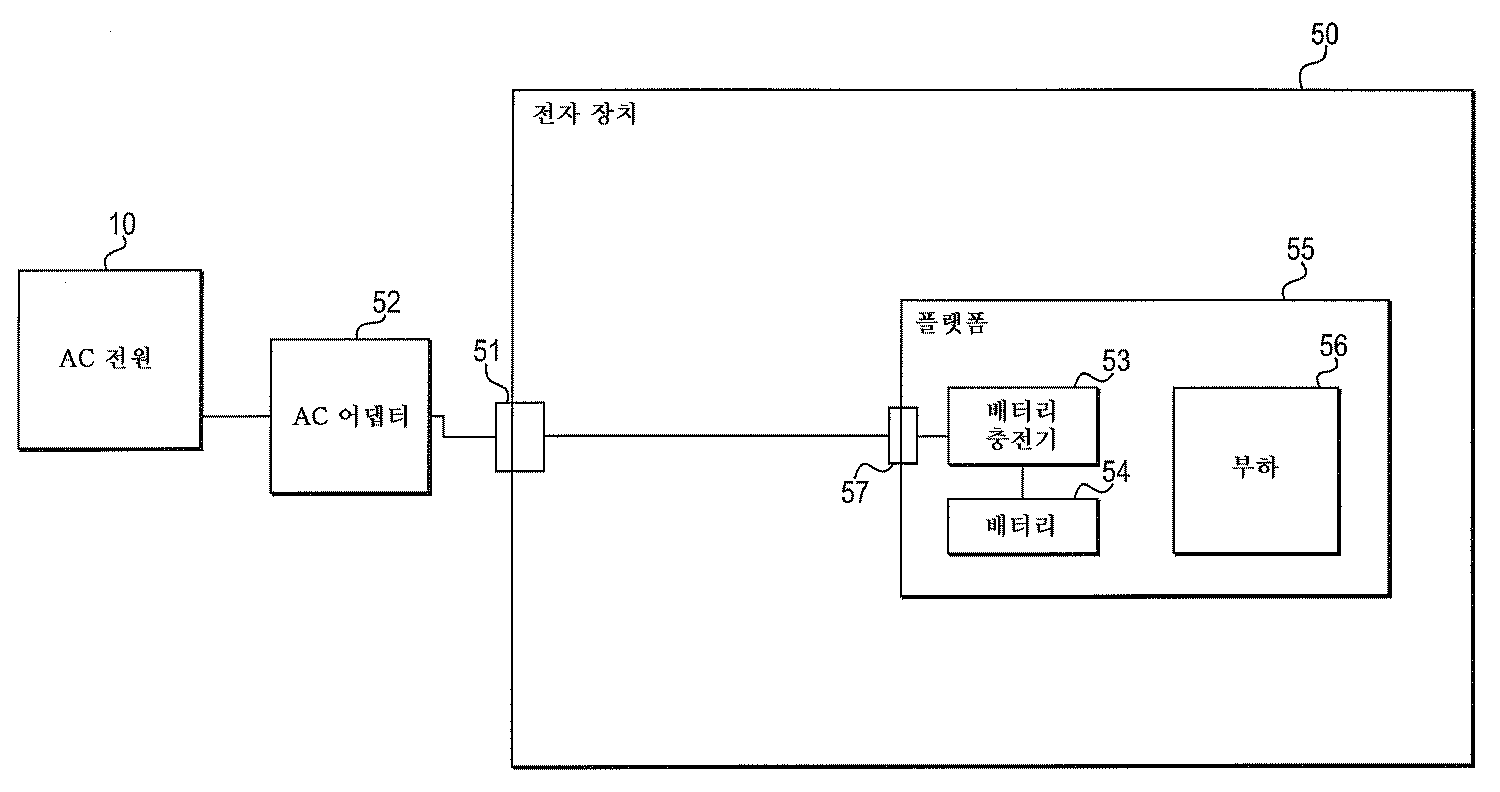
도 1은 예시적인 배열에 따른, AC 어댑터에 의해 급전되는 전자 장치의 도면이다. 다른 배열들 및 구성들도 제공될 수 있다.1 is a diagram of an electronic device powered by an AC adapter, in accordance with an exemplary arrangement; Other arrangements and configurations may be provided.
더 구체적으로, 도 1은 교류(AC) 전원(10)에 직접 결합되는 전자 장치(50)를 나타낸다. AC 전원(10)은 AC 전력을 AC 어댑터(52)에 제공할 수 있으며, 이 AC 어댑터는 전자 장치(50)를 위한 직류(DC)를 제공할 수 있다. AC 어댑터(52)는 AC/DC 어댑터로도 지칭될 수 있다. 수신된 전력은 전자 장치(50)의 컴포넌트들에 급전하는 데 사용될 수 있다. 수신된 전력은 전자 장치(50)의 배터리 포트 내에 제공되는 배터리 내에 저장될 수도 있다. AC 어댑터(52)(및/또는 AC/DC 어댑터)는 전자 장치의 외부에 위치할 수 있다.More specifically, FIG. 1 shows an
전자 장치(50)는 모바일 단말기, 모바일 장치, 모바일 컴퓨팅 플랫폼, 랩탑 컴퓨터, 태블릿, 울트라-모바일 개인용 컴퓨터, 모바일 인터넷 장치, 스마트폰, 개인 휴대 단말기, 텔레비전(TV) 세트, 모니터 및/또는 기타 등등일 수 있다. 다른 전자 장치들도 사용될 수 있다.The
전자 장치(50)는 (AC 어댑터(52)에 결합되는) 입력 포트(51), 및 입력 포트(57), 배터리 충전기(53), 배터리(54)(또는 다른 전하 저장 장치)를 수용하는 배터리 포트 및 부하(56)를 포함하는 플랫폼(55)을 포함할 수 있다. 플랫폼(55)은 예를 들어 모바일 플랫폼일 수 있다.The
부하(56)는 수신 전압에 기초하여 동작하는 전자 장치(50) 상의 (또는 전자 장치(50)에 결합되는) 임의의 장치 또는 컴포넌트일 수 있다. 예를 들어, 부하(56)는 디스플레이 장치, 메모리, 프로세서, 제어기, 입출력 장치 등일 수 있다.The
도 1은 AC 어댑터(52)가 전자 장치(50)의 외부에 위치하는(그리고 그로부터 분리된) 것을 보여준다.Figure 1 shows that the AC adapter 52 is located outside (and separated from) the
AC 전원(10)은 AC 전압(또는 AC 전력)을 입력 포트(51)에 제공할 수 있으며, 이어서 이 입력 포트는 AC 전압을 AC 어댑터(52)에 제공한다. AC 어댑터(52)는 수신된 AC 전압을 DC 전압으로 변환할 수 있다. AC 어댑터(52)는 AC/DC 어댑터 또는 AC/DC 컨버터로 간주될 수도 있다.The
AC 어댑터(52)가 전자 장치(50)의 외부에 위치하는 경우, AC 어댑터(52)는 AC 전원(10)으로부터 AC 전압을 수신하고, DC 전압을 입력 포트(57)에 (그리고 배터리 충전기(53)에 또는 직접 배터리(54)에) 제공할 수 있다. 설명의 편의를 위해, 아래의 설명은 전자 장치(50) 외부에 위치하는 AC 어댑터와 관련될 수 있다.When the AC adapter 52 is located outside of the
DC 전압은 입력 포트(57)로부터 배터리 충전기(53)(또는 충전기)로 제공될 수 있다. 배터리 충전기(53)는 DC 전압을 (배터리 포트에 제공된) 배터리(54)에 제공할 수 있다. DC 전압은 또한 또는 대안으로서 전자 장치(50)를 동작시키기 위해 부하(56)에 (직접 또는 배터리 충전기(53)를 통해 간접적으로) 제공될 수 있다. 예를 들어, DC 전압은 전자 장치(50) 상의 디스플레이 장치(또는 다른 컴포넌트)에 급전하는 데 사용될 수 있다. 전압 조절기도 전자 장치(50)의 플랫폼(55) 상에 제공되어, 부하에 제공되기 전에 전압을 안정시킬 수 있다. 배터리(54)는 일 구현에서 AC 어댑터(52) 출력에 직접 접속될 수 있다.The DC voltage may be provided from the input port 57 to the battery charger 53 (or charger). The battery charger 53 may provide a DC voltage to the battery 54 (provided in the battery port). The DC voltage may also or alternatively be provided to the load 56 (either directly or indirectly through the battery charger 53) to operate the
AC 어댑터(52)는 (50 헤르츠(Hz)의 저주파수와 같은) 특정 주파수에서 AC 전원(10)(즉, AC 아웃렛)으로부터 AC 전력을 수신하고, 예를 들어 AC 어댑터(52)가 사용되는 국가에 기초하여 (예로서, 90 Vrms로부터 265 Vrms로) 변할 수 있는 전압을 갖도록 설계될 수 있다.The AC adapter 52 receives AC power from an AC power source 10 (i.e., an AC outlet) at a particular frequency (such as a low frequency of 50 hertz (Hz) (E.g., from 90 Vrms to 265 Vrms).
전력 전달 시스템은 광범위한 최대 출력 전력들을 갖는 어댑터들을 수용하면서 시스템 크기를 최소화하고 시스템 성능을 최대화하는 것이 바람직할 수 있다. 적어도 하나의 배열에서, 하이브리드 전력 부스트(HPB) 시스템이 전력 전달 시스템으로 사용될 수 있다. 적어도 하나의 실시예에서, 좁은 VDC(NVDC) 시스템이 전력 전달 시스템으로 사용될 수 있다.It may be desirable for a power delivery system to accommodate adapters having a wide range of maximum output powers while minimizing system size and maximizing system performance. In at least one arrangement, a hybrid power boost (HPB) system may be used as the power delivery system. In at least one embodiment, a narrow VDC (NVDC) system may be used as the power delivery system.
도 2는 예시적인 배열에 따른 전력 전달 시스템의 도면이다. 다른 배열들 및 구성들도 제공될 수 있다.2 is a diagram of a power delivery system in accordance with an exemplary arrangement. Other arrangements and configurations may be provided.
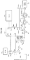
도 2는 하이브리드 전력 부스트(HPB) 시스템(또는 기술)을 이용하는 전력 전달 시스템을 나타낸다. 더 구체적으로, 도 2는 AC/DC 어댑터(110), 제어기(120), 충전기(130)(또는 충전기 제어기), (예로서, 배터리 포트 내의) 배터리(150) 및 부하(180)를 나타낸다. 도 2에 도시된 전력 전달 시스템의 컴포넌트들은 전자 장치 내에 제공될 수 있다.Figure 2 shows a power delivery system using a hybrid power boost (HPB) system (or technology). More specifically, FIG. 2 shows an AC /
도 2의 배열에서, 충전기는 부하(180)(또는 시스템)와 병렬인 것으로 간주된다. 동작 동안, AC/DC 어댑터는 전력을 부하(180)에 제공할 수 있으며, 전력을 배터리에 독립적으로 제공(즉, 배터리를 충전)할 수 있다.In the arrangement of FIG. 2, the charger is considered to be in parallel with the load 180 (or system). During operation, the AC / DC adapter can provide power to the
적어도 하나의 실시예에서, AC/DC 어댑터(110)는 전자 장치의 외부에 위치할 수 있다. 적어도 하나의 실시예에서, AC/DC 어댑터는 전자 장치의 내부에 위치할 수 있다.In at least one embodiment, the AC /
VDC는 최저 배터리 전압과 최고 어댑터 전압 사이에서 변할 수 있다.The VDC can vary between the lowest battery voltage and the highest adapter voltage.
전력 전달 시스템은 AC/DC 어댑터(110)와 직렬로 접속되는 제1 패스 스위치(112) 및 제2 패스 스위치(114)를 포함할 수 있다. 제1 패스 스위치(112) 및/또는 제2 패스 스위치(114)는 각각 개별 전계 효과 트랜지스터(FET)일 수 있다.The power delivery system may include a
감지 저항기(116)가 제1 및 제2 패스 스위치들(112, 114)과 직렬로 제공될 수 있다. 감지 저항기(116)는 전압 레일(190)을 따라 입력 전압(VIN)으로부터 출력 전압(VOUT)으로 전류를 전도하는 데 사용될 수 있다. 출력 전압(VOUT)은 전압 레일(190)을 따라 부하(180)에 제공될 수 있다.A
충전기(130)는 감지 저항기(116)의 양단에 접속될 수 있다. 충전기(130)는 충전기(130)의 입력들(IADP +, IADP -)에서 수신되는 신호들에 기초하여 전류(즉, 어댑터 전류)를 감지할 수 있다.The
배터리 스위치(140)(QBATT)가 전압 레일(190)과 배터리(150) 사이에 제공될 수 있다. 배터리 스위치(140)는 배터리(150)로부터 부하(180)로 전력을 제공할 수 있다. 배터리 스위치(140)는 AC/DC 어댑터(110)가 분리될 때 턴온될 수 있다. 이어서, 배터리(150)는 전력을 부하(180)에 제공할 수 있다.A battery switch 140 (Q BATT ) may be provided between the
전력 전달 시스템은 제1 충전기 스위치(132) 및 제2 충전기 스위치(134)도 포함할 수 있다. 제1 충전기 스위치(132) 및 제2 충전기 스위치(134)는 각각 전계 효과 트랜지스터(FET)일 수 있다. 제1 충전기 스위치(132)는 전압 레일(190)과 노드(133) 사이에 결합될 수 있다. 제2 충전기 스위치(134)는 노드(133)와 접지 사이에 결합될 수 있다. 제1 및 제2 충전기 스위치들(132, 134)은 충전기(130)에 의해 독립적으로 제어될 수 있다. 일례로서, 제1 및 제2 충전기 스위치들(132, 134)은 전력을 부하(180)에 제공하기 위한 부스트 컨버터로서 동작하도록 제어될 수 있다. 예를 들어, 제1 및 제2 충전기 스위치들(132, 134)은 부스트 컨버터로서 동작할 수 있으며, 따라서 배터리(150)는 전력을 부하(180)에 제공할 때 AC/DC 어댑터(110)를 보조할 수 있다.The power delivery system may also include a
HPB를 사용하는 도 2의 배열의 일례로서, AC/DC 어댑터(110)가 전력 전달 시스템의 컴포넌트들에 물리적으로 접속될 때, 제1 및 제2 패스 스위치들(112, 114)(QADP1, QADP2)은 충전기(130)(ADPDRV 출력)에 의해 턴온될 수 있고, 배터리 스위치(140)(Qbatt)는 충전기(130)(GBATT 출력)에 의해 턴오프될 수 있다. 충전기(130)는 제1 및 제2 충전기 스위치들(132, 134)(QCHR _SW, QCHR _ SYN)을 제어하여 배터리(150)를 충전하도록 스위칭할 수 있다. 제1 및 제2 충전기 스위치들(132, 134)은 충전기(130)(또는 충전기 제어기)에 의해 벅 컨버터로서 동작할 수 있으며, 배터리(150)를 충전하는 데 사용될 수 있다.As an example of the arrangement of FIG. 2 using HPB, when AC /
충전기(130)는 감지 저항기(116)(RADP)를 통해 전류(즉, 어댑터 출력 전류)를 모니터링할 수 있다. 충전기(130)가 전류가 규정 한도를 초과하는 것으로 결정할 때, 충전기(130)는 제1 및 제2 충전기 스위치들(132, 134)을 제어하여 부스트 컨버터로서 동작하게 할 수 있으며, 배터리(150)는 전력을 부하(180)에 제공함으로써 AC/DC 어댑터(110)를 보조할 수 있다.
도 2의 배열의 전력 전달 시스템은 전류가 규정 한도를 초과하는 것으로 결정될 때 AC/DC 어댑터(110) 및 배터리(150) 양자로부터 전압을 제공하도록 동작할 수 있다.The power delivery system of the arrangement of FIG. 2 may operate to provide a voltage from both the AC /
도 3은 예시적인 배열에 따른 전력 전달 시스템의 도면이다. 다른 배열들 및 구성들도 제공될 수 있다.3 is a diagram of a power delivery system in accordance with an exemplary arrangement. Other arrangements and configurations may be provided.
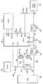
도 3은 좁은 VDC(NVDC) 시스템을 이용하는 전력 전달 시스템을 나타낸다. NVDC 시스템은 전력 경로 선택 아키텍처를 이용할 수 있다. NVDC 시스템은 배터리 충전기 및 전력 경로 선택 스위치들을 포함할 수 있다. NVDC 시스템은 AC/DC 어댑터가 물리적으로 접속되고 온 상태일 때 AC/DC 어댑터가 충전기(130) 및 그의 전력 스위치들(132, 134) 및 인덕터(135)를 통해 VDC 노드에 접속되도록 동작할 수 있다. AC/DC 어댑터가 더 이상 접속되지 않을 때, 배터리는 배터리 스위치를 통해 VDC 노드에 접속되어, 전력을 (예로서, DC/DC 컨버터를 통해) 부하에 제공할 수 있다.Figure 3 shows a power delivery system using a narrow VDC (NVDC) system. The NVDC system may utilize a power path selection architecture. The NVDC system may include a battery charger and power path selection switches. The NVDC system can operate such that the AC / DC adapter is connected to the VDC node through
더 구체적으로, 도 3은 AC/DC 어댑터(110), 제어기(120), 충전기(130), 배터리(150)(또는 배터리 포트) 및 부하(180)를 나타낸다. 도 3에 도시된 전력 전달 시스템의 컴포넌트들은 전자 장치 내에 제공될 수 있다.3 shows an AC /
도 3의 배열에서, 충전기는 부하(180)(또는 시스템)와 직렬인 것으로 간주된다. AC/DC 어댑터가 전력 전달 시스템에 접속되지 않는 경우, 전력은 배터리로부터 제공될 수 있다.In the arrangement of FIG. 3, the charger is considered to be in series with the load 180 (or system). If the AC / DC adapter is not connected to the power delivery system, power may be provided from the battery.
전력 전달 시스템은 AC/DC 어댑터(110)와 직렬로 접속되는 제1 패스 스위치(112) 및 제2 패스 스위치(114)를 포함할 수 있다. 감지 저항기(116)는 제1 및 제2 패스 스위치들(112, 114)과 직렬로 제공될 수 있다. 감지 저항기(116)는 입력 전압(Vin)을 수신할 수 있다.The power delivery system may include a
충전기(130)(또는 충전기 제어기)는 감지 저항기(116)의 양단에 접속될 수 있다. 충전기(130)(또는 충전기 제어기)는 충전기(130)에 대한 입력들(IADP +, IADP -)에서 수신되는 신호들에 기초하여 전류(즉, 어댑터 전류)를 감지할 수 있다.The charger 130 (or the charger controller) may be connected to both ends of the
배터리 스위치(240)(QBATT)가 배터리 저항기(RBATT)와 배터리(150) 사이에 제공되어, 전력을 배터리(150)에 제공할 수 있다. 충전기(130)의 출력 신호(GBATT 출력)가 배터리 스위치(240)의 상태를 제어할 수 있다. 배터리 스위치(240)는 AC/DC 어댑터가 분리될 때 턴온될 수 있다. 이어서, 배터리(150)는 전력을 부하(180)에 제공할 수 있다.A battery switch 240 (Q BATT ) may be provided between the battery resistor R BATT and the
전력 전달 시스템은 직렬로 제공되는 제1 및 제2 충전기 스위치들(132, 134)도 포함할 수 있다. 제1 충전기 스위치(132)는 전압 레일과 노드(133) 사이에 결합될 수 있다. 제2 충전기 스위치(134)는 노드(133)와 접지 사이에 결합될 수 있다. 제1 및 제2 충전기 스위치들(132, 134)은 충전기(130)에 의해 독립적으로 제어될 수 있다. 제1 및 제2 충전기 스위치들(132, 134)은 인덕터(135) 및 전압 레일(VDC로 도시됨)을 통해 부하(180)에 전력을 제공하도록 제어될 수 있다.The power delivery system may also include first and second charger switches 132, 134 provided in series. The
NVDC 시스템을 사용하는 도 3 배열의 일례로서, AC/DC 어댑터(110)가 전력 전달 시스템에 물리적으로 접속될 때, 제1 및 제2 패스 스위치들(112, 114)(QADP1, QADP2)은 충전기(130)(ADPDRV 출력)에 의해 턴온될 수 있고, 충전기(130)는 배터리(150)를 충전하는 것을 포함하여 모든 전력을 부하(180)에 제공할 수 있다. 충전기(130)(또는 충전기 제어기)는 제1 및 제2 충전기 스위치들(132, 134)을 제어하여 AC/DC 어댑터(110)의 전력을 부하(180)에 항상 접속되는 배터리(150)의 전압 레벨로 변환할 수 있다. 어댑터(110)로부터 나와서 충전기 회로에 의해 배터리 전압으로 변환된 전력은 배터리(150)를 충전하고 부하(180)(또는 시스템)의 전력 요구를 지원하는 데 사용될 수 있다. 부하(180)(또는 시스템) 전력 요구가 어댑터(110)의 전력 능력을 초과하는 경우, 배터리(150)는 어댑터(110)를 자동으로 보조할 수 있다.As an example of the arrangement of FIG. 3 using the NVDC system, when the AC /
적어도 일 배열에서, 전자 장치는 약 30W의 열 설계 전력(TDP)을 특징으로 할 수 있는 반면, 터보 레벨은 예로서 45W일 수 있다. 시스템 크기를 최소화하기 위해, 충전기의 최대 전력은 약 12W만으로 제한될 수 있으며, 이는 제1 및 제2 충전기 스위치들이 충전기 제어기 내에 통합되는 것을 가능하게 할 수 있다.In at least one arrangement, the electronic device may feature a thermal design power (TDP) of about 30 W, while the turbo level may be 45 W, for example. To minimize system size, the maximum power of the charger may be limited to only about 12 W, which may enable the first and second charger switches to be integrated within the charger controller.
그러나, 사용자는 AC/DC 어댑터에 대한 두 가지 상이한 선택, 즉 시스템 동작 및 배터리 충전을 가능하게 하는 더 큰 유닛(예로서, 45W 유닛) 및 여행 및 야간 충전을 위해 양호할 수 있는 더 작은 유닛(예로서, 12W 유닛)을 갖기를 원할 수 있다.However, the user has two different choices for the AC / DC adapter: a larger unit (e.g., a 45W unit) that allows for system operation and battery charging, and a smaller unit that may be good for travel and night charging For example, a 12W unit).
HPB 시스템을 이용하는 전력 전달은 (45W 어댑터와 같은) 더 큰 어댑터를 충분히 이용할 수 있지만, (12W 어댑터와 같은) 더 작은 어댑터를 지원하지 못할 수 있는데, 그 이유는 충전기가 충분히 긴 기간 동안 33W를 갖는 어댑터를 보조하지 못할 수 있기 때문이다. 결과적으로, 작은 어댑터가 사용될 때 전력 전달을 갖는 시스템에 대한 터보 레벨들이 제한될 수 있다.Power delivery using the HPB system may take advantage of a larger adapter (such as a 45W adapter), but may not support a smaller adapter (such as a 12W adapter) because the charger has 33W for a sufficiently long period of time This is because the adapter may not be able to support it. As a result, turbo levels for a system with power transfer can be limited when a small adapter is used.
한편, NVDC 시스템은 더 큰 어댑터(45W)가 전력 전달 시스템에 접속될 때 많은 개선을 제공하지 못할 수 있다. 그러나, 시스템은 큰 어댑터를 사용할 때에도 배터리를 방전할 수 있다. 더 작은 어댑터(12W)가 사용될 때, 시스템은 어떠한 문제도 없이 작은 어댑터를 충분히 이용할 수 있다.On the other hand, the NVDC system may not provide much improvement when a larger adapter 45W is connected to the power delivery system. However, the system can discharge the battery even when using a large adapter. When a smaller adapter 12W is used, the system can take full advantage of the smaller adapter without any problems.
실시예들은 HPB 전력 전달 시스템들(도 2) 및 좁은 VDC(NVDC) 전력 전달 시스템들(도 3) 양자를 이용하기 위한 전력 전달 시스템을 제공할 수 있다. 도 2의 전력 전달 시스템은 전력 전달 시스템이 큰 AC/DC 어댑터로부터 동작할 때 사용될 수 있는 반면, 도 3의 NVDC 전력 전달 시스템은 전력 전달 시스템이 작은 AC/DC 어댑터로부터 동작할 때 전력 시스템을 위해 사용될 수 있다.Embodiments can provide a power delivery system for using both HPB power delivery systems (FIG. 2) and narrow VDC (NVDC) power delivery systems (FIG. 3). The power delivery system of FIG. 2 may be used when the power delivery system operates from a large AC / DC adapter, while the NVDC power delivery system of FIG. 3 may be used for power systems when the power delivery system operates from a small AC / Can be used.
실시예들은 시스템 성능 및 작은 충전기에 대한 제한 없이 (작고 큰 양자의) 어댑터들의 유연한 사용을 가능하게 할 수 있다. 사용자는 더 작은 시스템들을 사용하고, 여행 어댑터 또는 더 큰 어댑터의 사용 중에서 선택할 수 있다.Embodiments may enable flexible use of adapters (small and large quantities) without limitations on system performance and small chargers. Users can choose between using smaller systems and using travel adapters or larger adapters.
도 4는 예시적인 실시예에 따른 전력 전달 시스템의 도면이다. 다른 실시예들 및 구성들도 제공될 수 있다.4 is a diagram of a power delivery system in accordance with an exemplary embodiment. Other embodiments and configurations may be provided.
도 4는 (입력 포트에서의) AC/DC 어댑터(110), 제어기(120), 충전기(130), 배터리(150)(또는 배터리 포트) 및 부하(180)를 나타낸다. 도 4에 도시된 전력 전달 시스템의 컴포넌트들은 도 1에 도시된 전자 장치(50)와 같은 전자 장치 내에 제공될 수 있다.4 shows the AC /
도 4의 실시예에서, 전력 전달 시스템은 더 큰 어댑터가 접속될 때 (HPB 시스템과 같은) 제1 모드에서 동작할 수 있으며, 전력 전달 시스템은 더 작은 어댑터가 접속될 때 (NVDC 시스템과 같은) 제2 모드에서 동작할 수 있다. 회로는 입력 포트에 결합될 AC/DC 어댑터의 타입을 결정할 수 있으며, 회로는 결정된 AC/DC 어댑터의 타입에 기초하여 전력 흐름을 제어(또는 변경)할 수 있다. 일례로서, 더 큰 어댑터는 제1 전력 레벨을 갖는 제1 타입의 어댑터로 간주될 수 있으며, 제2 어댑터는 제2 전력 레벨을 갖는 제2 타입의 어댑터로 간주될 수 있다.In the embodiment of FIG. 4, the power delivery system may operate in a first mode (such as an HPB system) when a larger adapter is connected, and the power delivery system may operate when a smaller adapter is connected (such as an NVDC system) And can operate in the second mode. The circuit can determine the type of AC / DC adapter to be coupled to the input port and the circuit can control (or change) the power flow based on the determined type of AC / DC adapter. As an example, a larger adapter may be regarded as a first type of adapter having a first power level, and a second adapter may be considered as a second type of adapter having a second power level.
적어도 하나의 실시예에서, AC/DC 어댑터(110)는 전자 장치의 일부로서 간주될 수 있다.In at least one embodiment, the AC /
전력 전달 시스템은 AC/DC 어댑터(110)와 전압 레일(290) 사이에 직렬로 접속되는 제1 패스 스위치(212), 감지 저항기(216) 및 제2 패스 스위치(214)를 포함할 수 있다. 제1 패스 스위치(212) 및/또는 제2 패스 스위치(214)는 각각 개별 전계 효과 트랜지스터(FET)일 수 있다. 전압 레일(290)은 부하(180)에 결합될 수 있다. 제1 패스 스위치(212) 및 제2 패스 스위치(214)는 충전기(130)에 의해 개별적으로 그리고 독립적으로 제어될 수 있다.The power delivery system may include a
감지 저항기(216)는 또한 제1 패스 스위치(212)와 제2 패스 스위치(214) 사이에 제공될 수 있다. 충전기(130)는 AC/DC 어댑터의 결정된 전력 레벨에 기초하여 스위치들(또는 스위치 장치들)을 개별적으로 제어할 수 있다.The
충전기(130)는 전류 저항기(216)의 양단에 접속될 수 있다. 충전기(130)는 충전기(130)의 입력들(IADP + 및 IADP -)에서 수신되는 신호들에 기초하여 전류(즉, 어댑터 전류)를 감지할 수 있다.The
배터리 스위치(250)(QBATT)가 전압 레일(290)과 노드(255) 사이에 제공될 수 있다. 배터리 스위치는 전계 효과 트랜지스터일 수 있다.A battery switch 250 (Q BATT ) may be provided between the
배터리 저항기(260)(RBATT)가 노드(255)와 배터리(150) 사이에 제공될 수 있다. 충전기(130)는 배터리 저항기(260)(RBATT)의 양단에 접속될 수 있다. 따라서, 배터리 스위치(250), 배터리 저항기(260) 및 배터리(150)는 직렬로 결합될 수 있다. 충전기(130)는 충전기(130)의 입력들(IBATT +, IBATT -)에서 수신되는 신호들에 기초하여 전류를 감지하고, 이를 이용하여 배터리 충전/방전 전류를 제어할 수 있다.A battery resistor 260 (R BATT ) may be provided between the
전력 전달 시스템은 제1 충전기 스위치(232) 및 제2 충전기 스위치(234)도 포함할 수 있다. 제1 충전기 스위치(232) 및 제2 충전기 스위치(234)는 전계 효과 트랜지스터들일 수 있다. 제1 충전기 스위치(232)는 노드(215)와 노드(233) 사이에 결합될 수 있다. 제2 충전기 스위치(234)는 노드(233)와 접지 사이에 결합될 수 있다. 제1 충전기 스위치(232) 및 제2 충전기 스위치(234)는 충전기(130)에 의해 제어될 수 있다.The power delivery system may also include a
게다가, 인덕터(235)가 노드(233)와 노드(255) 사이에 제공될 수 있다.In addition, an
도 4는 제1 패스 스위치(212) 및 제2 패스 스위치(214)가 제1 패스 스위치(212)와 제2 패스 스위치(214) 사이에 제공되는 감지 저항기(216)에 의해 서로 분리된다는 것을 보여준다. 도 4는 제1 및 제2 충전기 스위치들(232, 234)이 감지 저항기(216)와 제2 패스 스위치(214) 사이의 노드(215)에 접속된다는 것도 보여준다. 이것은 AC/DC 어댑터(110)로부터의 전류가 제1 패스 스위치(212), 감지 저항기(215), 제1 충전기 스위치(232) 및 인덕터(235)를 통해 흘러서 노드(255)에 도달하고 배터리(150)를 충전하는 것을 가능하게 할 수 있다.4 shows that the
입력 AC/DC 어댑터(110)의 크기의 함수로서의 회로의 동작이 아래에서 설명될 수 있다.The operation of the circuit as a function of the size of the input AC /
충전기(130)(또는 회로)는 입력 노드에 접속된 AC/DC 어댑터(110)의 전력 능력을 결정할 수 있다. 결정된 전력(또는 AC/DC 어댑터의 전력 레벨)에 기초하여, 전력 전달 시스템은 제1 전력 흐름을 제공함으로써 제1 모드에서 동작할 수 있거나, 제2 전력 흐름을 제공함으로써 제2 모드에서 동작할 수 있다. 회로는 AC/DC 어댑터의 제1 전력 레벨에 기초하여 제1 전력 흐름을 제공할 수 있고, 회로는 AC/DC 어댑터의 제2 전력 레벨에 기초하여 제2 전력 레벨을 제공할 수 있다.The charger 130 (or circuit) may determine the power capability of the AC /
(HPB 시스템과 같은) 제1 모드에서, 제1 및 제2 패스 스위치들(212, 214)은 온 상태일 수 있고, 배터리 스위치(250)는 오프 상태일 수 있다. 이어서, 제1 전력 흐름은 전압 레일을 따라 AC/DC 어댑터로부터 부하(180)로 향할 수 있고, 배터리(150)는 제1 및 제2 충전기 스위치들(232, 234) 및 인덕터(235)의 동작에 의해 충전될 수 있다. 일례로서, 충전기 스위치들(232, 234)은 상보 모드에서 스위칭하고, 인덕터(235)와 함께 벅 컨버터를 형성할 수 있다.In a first mode (such as an HPB system), the first and second pass switches 212 and 214 may be on and the
(NVDC 시스템과 같은) 제2 모드에서, 제1 패스 스위치(212)는 온 상태일 수 있고, 제2 패스 스위치(214)는 오프 상태일 수 있으며, 배터리 스위치(250)는 온 상태일 수 있다. 이어서, 제2 전력 흐름은 배터리(150)의 충전을 포함해서 제1 충전기 스위치(232)를 통해 인덕터(235)를 통해 AC/DC 어댑터(110)로부터 부하(180)로 향할 수 있다. 충전기 스위치들(232, 234)은 상보 모드에서 스위칭할 수 있고, 인덕터(235)와 함께 벅 컨버터를 형성할 수 있다.In a second mode (such as an NVDC system), the
(예로서, 충전기보다 큰 출력 전력 능력을 갖는) 큰 AC/DC 어댑터(110)가 전력 전달 시스템에 접속될 때, 제1 및 제2 패스 스위치들(212, 214)은 턴온될 수 있고, 배터리 스위치(250)는 턴오프될 수 있다. 전력 전달 시스템은 도 2의 배열과 동일한 방식으로 동작할 수 있으며, 충전기(130)는 부하(180)와 병렬일 수 있다.When the large AC / DC adapter 110 (having, for example, greater than the charger output power capability) is connected to the power delivery system, the first and second pass switches 212 and 214 can be turned on, The
45W 어댑터(즉, 큰 어댑터)가 전력 전달 시스템에 접속되는 일례에서, (예로서, 12W를 전달하도록 설계된) 충전기(130)는 AC/DC 어댑터(110)로부터의 12W를 계속 동시에 이용하여 배터리(150)를 충전할 수 있고, 부하(180)에 대해 AC/DC 어댑터(110)로부터의 최대 33W를 이용할 수 있다. 어댑터로부터 계속 소비되는 전체 전력은 예를 들어 45W일 수 있다. 부하 전력 소비가 어댑터의 전력 능력을 초과하는 경우, 충전기는 스위치들(232, 234) 및 인덕터(235)를 부스트 컨버터로서 동작시켜, 배터리(150) 출력 전력을 이용하여 어댑터(110) 출력 전력을 보조할 수 있다.In an example where a 45W adapter (i.e., a large adapter) is connected to the power delivery system, a charger 130 (e.g., designed to deliver 12W) continues to use 12W from the AC / 150 and can utilize up to 33 W from the AC /
작은 AC/DC 어댑터(110)(예로서, 15W 어댑터)가 전력 전달 시스템에 접속되는 일례에서, 제1 패스 스위치(212)는 온 상태일 수 있고, 제2 패스 스위치(214)는 오프 상태일 수 있다. 배터리 스위치(250)는 턴온될 수 있고, 배터리(150)는 배터리 스위치(250)를 통해 부하(180)에 접속될 수 있다. 이 예에서, 충전기(130)는 도 3의 배열과 동일한 방식으로 동작할 수 있으며, 충전기(130)는 부하(180)(또는 시스템)와 직렬일 수 있다. 충전기(130)는 NVDC 시스템으로서 동작할 수 있다. 즉, 어댑터(110)로부터 부하(180)로 전달되는 전력은 충전기(130)의 설계 전력을 초과하지 않을 수 있다. 부하 전력 소비가 어댑터의 전력 능력을 초과하는 경우, 충전기는 전류 제한 모드에서 동작할 수 있으며, 배터리(150)는 충전기 출력 전력을 보조할 수 있다.In one example where a small AC / DC adapter 110 (e.g., a 15 W adapter) is connected to the power delivery system, the
아래의 예들은 추가 실시예들과 관련된다.The following examples relate to further embodiments.
예 1은 부하, 교류/직류(AC/DC) 어댑터를 수용하는 입력 포트, 배터리를 수용하는 배터리 포트, 및 상기 입력 포트에 결합될 때 상기 AC/DC 어댑터의 타입을 결정하고, 상기 AC/DC 어댑터의 상기 결정된 타입에 기초하여 상기 부하로의, 상기 배터리로의 또는 상기 부하와 상기 배터리 양자로의 전력 흐름을 제어하는 회로를 포함하는 전자 장치이다.Example 1 determines the type of the AC / DC adapter when coupled to the input port, a battery port that accepts a battery, and an AC / DC adapter that accepts a load, an AC / DC adapter, And a circuit for controlling power flow to the load, to the battery, or both to the load and the battery, based on the determined type of adapter.
예 2에서, 예 1의 발명은 상기 회로가 적어도 하나의 스위치 장치를 제어함으로써 상기 전력 흐름을 제어하는 것을 임의로 포함할 수 있다.In Example 2, the invention of Example 1 may optionally include the circuit controlling the power flow by controlling at least one switching device.
예 3에서, 예 1의 발명은 상기 회로가 상기 AC/DC 어댑터의 제1 전력 레벨에 기초하여 제1 전력 흐름을 제공하고, 상기 회로가 상기 AC/DC 어댑터의 제2 전력 레벨에 기초하여 제2 전력 흐름을 제공하는 것을 임의로 포함할 수 있다.In Example 3, the invention of Example 1 is characterized in that the circuit provides a first power flow based on a first power level of the AC / DC adapter, RTI ID = 0.0 > 2 < / RTI > power flow.
예 4에서, 예 1 및 예 3의 발명은 상기 회로가 상기 AC/DC 어댑터의 상기 전력 레벨을 결정하는 충전기를 포함하는 것을 임의로 포함할 수 있다.In Example 4, the inventions of Examples 1 and 3 may optionally include that the circuit includes a charger that determines the power level of the AC / DC adapter.
예 5에서, 예 1 및 예 4의 발명은 상기 회로가 복수의 스위치 장치를 포함하고, 상기 충전기가 상기 AC/DC 어댑터의 상기 결정된 전력 레벨에 기초하여 상기 복수의 스위치 장치를 개별적으로 제어하는 것을 임의로 포함할 수 있다.In Example 5, the invention of Examples 1 and 4 is characterized in that the circuit comprises a plurality of switch devices, and the charger controls the plurality of switch devices individually based on the determined power level of the AC / DC adapter May optionally be included.
예 6에서, 예 1 및 예 4의 발명은 상기 충전기가 상기 전력 흐름이 상기 제1 전력 흐름일 때 상기 부하와 직렬인 것을 임의로 포함할 수 있다.In Example 6, the inventions of Examples 1 and 4 may optionally include the charger being in series with the load when the power flow is the first power flow.
예 7에서, 예 1 및 예 6의 발명은 상기 제1 전력 흐름이 상기 입력 포트로부터 상기 부하로 향하는 것을 임의로 포함할 수 있다.In Example 7, the inventions of Examples 1 and 6 may optionally include the first power flow from the input port to the load.
예 8에서, 예 1 및 예 4의 발명은 상기 충전기가 상기 전력 흐름이 상기 제2 전력 흐름일 때 상기 부하와 병렬인 것을 임의로 포함할 수 있다.In Example 8, the inventions of Examples 1 and 4 may optionally include the charger being in parallel with the load when the power flow is the second power flow.
예 9에서, 예 1의 발명은 상기 회로가 감지 저항기를 포함하는 것을 임의로 포함할 수 있다.In Example 9, the invention of Example 1 may optionally include the circuit comprising a sense resistor.
예 10에서, 예 1 및 예 9의 발명은 상기 전력 흐름이 상기 감지 저항기 양단의 전류가 규정 값을 초과할 때 상기 배터리를 향하는 것을 임의로 포함할 수 있다.In Example 10, the inventions of Examples 1 and 9 may optionally include the power flow directing the battery when the current across the sense resistor exceeds a specified value.
예 11에서, 예 1 및 예 10의 발명은 상기 회로가 상기 전력 흐름이 상기 배터리로 향할 때 사용될 부스트 컨버터를 포함하는 것을 임의로 포함할 수 있다.In Example 11, the inventions of Examples 1 and 10 may optionally include the circuit comprising a boost converter to be used when the power flow is to the battery.
예 12에서, 예 1 및 예 9의 발명은 상기 전력 흐름이 상기 감지 저항기 양단의 전류가 규정 값보다 작을 때 상기 부하를 향하는 것을 임의로 포함할 수 있다.In Example 12, the inventions of Examples 1 and 9 may optionally include the power flow directing to the load when the current across the sense resistor is less than a specified value.
예 13에서, 예 1 및 예 9의 발명은 상기 회로가 벅 컨버터를 포함하는 것을 임의로 포함할 수 있다.In Example 13, the inventions of Examples 1 and 9 may optionally include those in which the circuit includes a buck converter.
예 14는 교류/직류(AC/DC)의 타입을 결정하는 회로, 및 상기 AC/DC 어댑터의 상기 결정된 타입에 기초하여 전력 흐름을 제어하는 회로를 포함하는 기기이다.Example 14 is a device including a circuit for determining the type of AC / DC (AC / DC) and a circuit for controlling the power flow based on the determined type of the AC / DC adapter.
예 15에서, 예 14의 발명은 상기 회로가 적어도 하나의 스위치 장치를 제어함으로써 상기 전력 흐름을 제어하는 것을 임의로 포함할 수 있다.In Example 15, the invention of Example 14 may optionally include the circuit controlling the power flow by controlling at least one switch device.
예 16에서, 예 14의 발명은 상기 회로가 상기 AC/DC 어댑터의 제1 전력 레벨에 기초하여 제1 전력 흐름을 제공하고, 상기 회로가 상기 AC/DC 어댑터의 제2 전력 레벨에 기초하여 제2 전력 흐름을 제공하는 것을 임의로 포함할 수 있다.In Example 16, the invention of Example 14 is characterized in that the circuit provides a first power flow based on a first power level of the AC / DC adapter, RTI ID = 0.0 > 2 < / RTI > power flow.
예 17에서, 예 14 및 예 16의 발명은 상기 회로가 상기 AC/DC 어댑터의 상기 전력 레벨을 결정하는 충전기를 포함하는 것을 임의로 포함할 수 있다.In Example 17, the inventions of Examples 14 and 16 may optionally include a charger in which the circuit determines the power level of the AC / DC adapter.
예 18에서, 예 14 및 예 17의 발명은 상기 회로가 복수의 스위치 장치를 포함하고, 상기 충전기가 상기 AC/DC 어댑터의 상기 결정된 전력 레벨에 기초하여 상기 복수의 스위치 장치를 개별적으로 제어하는 것을 임의로 포함할 수 있다.In Example 18, the invention of Examples 14 and 17 is characterized in that the circuit includes a plurality of switch devices, and the charger controls the plurality of switch devices individually based on the determined power level of the AC / DC adapter May optionally be included.
예 19에서, 예 14의 발명은 상기 회로가 감지 저항기를 포함하는 것을 임의로 포함할 수 있다.In Example 19, the invention of Example 14 may optionally include that the circuit comprises a sense resistor.
예 20에서, 예 14의 발명은 상기 회로가 부스트 컨버터를 포함하는 것을 임의로 포함할 수 있다.In Example 20, the invention of Example 14 may optionally include the circuit comprising a boost converter.
예 21에서, 예 14의 발명은 상기 회로가 벅 컨버터를 포함하는 것을 임의로 포함할 수 있다.In Example 21, the invention of Example 14 may optionally include the circuit comprising a buck converter.
예 22는 교류/직류(AC/DC) 어댑터의 타입을 결정하기 위한 수단, 및 상기 AC/DC 어댑터의 상기 결정된 타입에 기초하여 전력 흐름을 제어하기 위한 수단을 포함하는 기기이다.Example 22 is a device comprising means for determining the type of an AC / DC adapter and means for controlling power flow based on the determined type of the AC / DC adapter.
예 23에서, 예 22의 발명은 제어하기 위한 상기 수단이 적어도 하나의 스위치 장치를 제어함으로써 상기 전력 흐름을 변경하는 것을 임의로 포함할 수 있다.In Example 23, the invention of Example 22 can optionally include changing said power flow by said means for controlling by controlling at least one switching device.
예 24에서, 예 22의 발명은 제어하기 위한 상기 수단이 상기 AC/DC 어댑터의 제1 전력 레벨에 기초하여 제1 전력 흐름을 제공하고, 제어하기 위한 상기 수단이 상기 AC/DC 어댑터의 제2 전력 레벨에 기초하여 제2 전력 흐름을 제공하는 것을 임의로 포함할 수 있다.In Example 24, the invention of Example 22 is characterized in that said means for controlling provide a first power flow based on a first power level of said AC / DC adapter, And optionally providing a second power flow based on the power level.
예 25에서, 예 22 및 예 24의 발명은 결정하기 위한 상기 수단이 상기 AC/DC 어댑터의 상기 전력 레벨을 결정하는 충전기를 포함하는 것을 임의로 포함할 수 있다.In Example 25, the invention of Examples 22 and 24 may optionally include said means for determining includes a charger for determining said power level of said AC / DC adapter.
예 26에서, 예 22 및 예 25의 발명은 제어하기 위한 상기 수단이 복수의 스위치 장치를 포함하고, 제어하기 위한 상기 수단이 상기 AC/DC 어댑터의 상기 결정된 전력 레벨에 기초하여 상기 복수의 스위치 장치를 개별적으로 제어하는 것을 임의로 포함할 수 있다.In Example 26, the invention of Examples 22 and 25 is characterized in that said means for controlling comprises a plurality of switch devices, and said means for controlling are connected to said switch devices < RTI ID = 0.0 > May be controlled separately.
예 27에서, 예 22의 발명은 제어하기 위한 상기 수단이 감지 저항기를 포함하는 것을 임의로 포함할 수 있다.In Example 27, the invention of Example 22 can optionally include that said means for controlling comprise a sense resistor.
예 28에서, 예 22의 발명은 제어하기 위한 상기 수단이 부스트 컨버터를 포함하는 것을 임의로 포함할 수 있다.In Example 28, the invention of Example 22 can optionally include those wherein said means for controlling comprise a boost converter.
예 29는 교류/직류(AC/DC)의 타입을 결정하는 단계, 및 AC/DC 어댑터의 상기 결정된 타입에 기초하여 전력 흐름을 제어하는 단계를 포함하는 방법이다.Example 29 is a method including determining the type of AC / DC (AC / DC) and controlling power flow based on the determined type of AC / DC adapter.
예 30에서, 예 29의 발명은 상기 전력 흐름을 제어하는 단계가 적어도 하나의 스위치 장치를 제어함으로써 상기 전력 흐름을 제어하는 단계를 포함하는 것을 임의로 포함할 수 있다.In Example 30, the invention of Example 29 can optionally include the step of controlling the power flow, the step of controlling the power flow by controlling at least one switching device.
예 31에서, 예 29의 발명은 상기 전력 흐름을 제어하는 단계가 상기 AC/DC 어댑터의 제1 전력 레벨에 기초하여 제1 전력 흐름을 제공하는 단계, 및 상기 AC/DC 어댑터의 제2 전력 레벨에 기초하여 제2 전력 흐름을 제공하는 단계를 포함하는 것을 임의로 포함할 수 있다.In Example 31, the invention of Example 29 is characterized in that the step of controlling the power flow comprises providing a first power flow based on a first power level of the AC / DC adapter and a second power level of the AC / And providing a second power flow based on the second power flow.
예 32에서, 예 29 및 예 31의 발명은 충전기가 상기 AC/DC 어댑터의 상기 전력 레벨을 결정하는 것을 임의로 포함할 수 있다.In Example 32, the invention of Examples 29 and 31 may optionally include a charger determining the power level of the AC / DC adapter.
예 33에서, 예 29 및 예 32의 발명은 상기 AC/DC 어댑터의 상기 결정된 전력 레벨에 기초하여 복수의 스위치 장치를 개별적으로 제어하는 단계를 임의로 포함할 수 있다.In Example 33, the inventions of Examples 29 and 32 may optionally include separately controlling a plurality of switch devices based on the determined power level of the AC / DC adapter.
본 명세서에서 "하나의 실시예", "실시예", "예시적인 실시예" 등에 대한 참조는 실시예와 관련하여 설명되는 특정 특징, 구조 또는 특성이 적어도 하나의 실시예 내에 포함된다는 것을 의미한다. 본 명세서 내의 다양한 곳에서의 그러한 표현의 출현은 모두가 반드시 동일한 실시예를 참조하지는 않는다. 또한, 특정 특징, 구조 또는 특성이 임의의 실시예와 관련하여 설명될 때, 그러한 특징, 구조 또는 특성을 실시예들 중 다른 실시예들과 관련하여 실시하는 것은 통상의 기술자의 이해 범위 내에 있다는 것을 제기한다.Reference herein to "one embodiment," "an embodiment," " an exemplary embodiment ", etc., means that a particular feature, structure, or characteristic described in connection with the embodiment is included in at least one embodiment . The appearances of such expressions in various places in this specification are not necessarily all referring to the same embodiment. Furthermore, when a particular feature, structure, or characteristic is described in connection with any embodiment, it is within the understanding of the ordinary artisan to practice such feature, structure, or characteristic in connection with other of the embodiments I will.
실시예들이 그의 다수의 예시적인 실시예들과 관련하여 설명되었지만, 본 개시 내용의 원리들의 사상 및 범위 내에 속하는 다수의 다른 변경 및 실시예가 통상의 기술자들에 의해 창안될 수 있다는 것을 이해해야 한다. 더 구체적으로, 본 개시 내용, 도면들 및 첨부된 청구항들의 범위 내에서 본 조합 배열의 컴포넌트 부분들 및/또는 배열들에서 다양한 변형들 및 변경들이 가능하다. 컴포넌트 부분들 및/또는 배열들에서의 변형들 및 변경들에 더하여, 통상의 기술자들에게 대안 사용들도 명백할 것이다.While the embodiments have been described in connection with a number of illustrative embodiments thereof, it should be understood that many other changes and embodiments that fall within the spirit and scope of the principles of this disclosure may be created by one of ordinary skill in the art. More specifically, various modifications and variations are possible in the component parts and / or arrangements of this combination arrangement within the scope of this disclosure, the drawings and the appended claims. In addition to variations and modifications in the component parts and / or arrangements, alternative uses will be apparent to those of ordinary skill in the art.
Claims (25)
교류/직류(AC/DC) 어댑터를 수용하는 입력 포트;
배터리를 수용하는 배터리 포트; 및
상기 입력 포트에 결합될 때 상기 AC/DC 어댑터의 타입을 결정하고, 상기 AC/DC 어댑터의 상기 결정된 타입에 기초하여 상기 부하로의, 상기 배터리로의, 또는 상기 부하와 상기 배터리 양자로의 전력 흐름을 제어하는 회로
를 포함하는 전자 장치.Load;
An input port for receiving an AC / DC adapter;
A battery port for receiving the battery; And
Determining a type of the AC / DC adapter when coupled to the input port; and determining a type of the AC / DC adapter to be coupled to the load, to the battery, Circuit for controlling flow
≪ / RTI >
상기 AC/DC 어댑터의 상기 결정된 타입에 기초하여 전력 흐름을 제어하는 회로
를 포함하는 기기.A circuit for determining the type of AC / DC; And
A circuit that controls power flow based on the determined type of the AC / DC adapter;
≪ / RTI >
상기 AC/DC 어댑터의 상기 결정된 타입에 기초하여 전력 흐름을 제어하기 위한 수단
을 포함하는 기기.Means for determining the type of AC / DC adapter; And
Means for controlling power flow based on the determined type of the AC / DC adapter
.
AC/DC 어댑터의 상기 결정된 타입에 기초하여 전력 흐름을 제어하는 단계
를 포함하는 방법.Determining a type of AC / DC (AC / DC); And
Controlling power flow based on the determined type of AC / DC adapter
≪ / RTI >
Applications Claiming Priority (1)
| Application Number | Priority Date | Filing Date | Title |
|---|---|---|---|
| PCT/US2013/078127 WO2015099794A1 (en) | 2013-12-27 | 2013-12-27 | Power delivery system for an electronic device |
Related Child Applications (1)
| Application Number | Title | Priority Date | Filing Date |
|---|---|---|---|
| KR1020187037057A Division KR20190000379A (en) | 2013-12-27 | 2013-12-27 | Power delivery system for an electronic device |
Publications (1)
| Publication Number | Publication Date |
|---|---|
| KR20160077148A true KR20160077148A (en) | 2016-07-01 |
Family
ID=53479453
Family Applications (2)
| Application Number | Title | Priority Date | Filing Date |
|---|---|---|---|
| KR1020167013954A KR20160077148A (en) | 2013-12-27 | 2013-12-27 | Power delivery system for an electronic device |
| KR1020187037057A KR20190000379A (en) | 2013-12-27 | 2013-12-27 | Power delivery system for an electronic device |
Family Applications After (1)
| Application Number | Title | Priority Date | Filing Date |
|---|---|---|---|
| KR1020187037057A KR20190000379A (en) | 2013-12-27 | 2013-12-27 | Power delivery system for an electronic device |
Country Status (5)
| Country | Link |
|---|---|
| US (1) | US20160261132A1 (en) |
| EP (1) | EP3087652A4 (en) |
| KR (2) | KR20160077148A (en) |
| CN (1) | CN105745812A (en) |
| WO (1) | WO2015099794A1 (en) |
Families Citing this family (9)
| Publication number | Priority date | Publication date | Assignee | Title |
|---|---|---|---|---|
| US20170093173A1 (en) * | 2015-09-24 | 2017-03-30 | Han Kung Chua | Front end charger bypass switch with linear regulation function and path for reverse boost |
| US20180076647A1 (en) * | 2016-09-13 | 2018-03-15 | Intersil Americas LLC | Hybrid power buck-boost charger |
| US10250059B2 (en) | 2016-09-19 | 2019-04-02 | Microsoft Technology Licensing, Llc | Charging circuit for battery-powered device |
| JP6645396B2 (en) * | 2016-10-07 | 2020-02-14 | 株式会社デンソー | Semiconductor device |
| US10551894B2 (en) * | 2016-11-03 | 2020-02-04 | Microsoft Technology Licensing, Llc | Dynamic power management in a hybrid dual battery system |
| JP2019062690A (en) * | 2017-09-27 | 2019-04-18 | パナソニックIpマネジメント株式会社 | Charger and electronic apparatus |
| CN107947290A (en) * | 2017-12-21 | 2018-04-20 | 联想(北京)有限公司 | A kind of charging equipment and method |
| US11135934B2 (en) * | 2019-09-06 | 2021-10-05 | Nio Usa, Inc. | Vehicle power devices, systems, and methods for sleep mode |
| CN116670967A (en) * | 2021-05-27 | 2023-08-29 | 华为技术有限公司 | Charging and discharging circuit and terminal equipment |
Family Cites Families (19)
| Publication number | Priority date | Publication date | Assignee | Title |
|---|---|---|---|---|
| US5625275A (en) * | 1995-05-24 | 1997-04-29 | Ast Research, Inc. | Power supply which provides a variable charging current to a battery in a portable computer system |
| US6144187A (en) * | 1998-11-12 | 2000-11-07 | Fairchild Semiconductor Corporation | Power measurement for adaptive battery charger |
| US6326771B1 (en) * | 1999-03-08 | 2001-12-04 | 02 Micro International Limited | Buffer battery power supply system |
| US6300744B1 (en) * | 2000-02-10 | 2001-10-09 | Siliconix Incorporated | High-efficiency battery charger |
| US7348760B2 (en) * | 2000-09-21 | 2008-03-25 | O2Micro International Limited | Power management topologies |
| JP4349773B2 (en) * | 2002-04-12 | 2009-10-21 | 日立コンピュータ機器株式会社 | Battery charging method and backup power supply apparatus for implementing the charging method |
| US7615965B2 (en) * | 2004-05-14 | 2009-11-10 | O2Micro International Limited | Power management system |
| US7391184B2 (en) * | 2005-02-16 | 2008-06-24 | Dell Products L.P. | Systems and methods for integration of charger regulation within a battery system |
| US7719236B2 (en) * | 2005-02-18 | 2010-05-18 | O2Micro International Limited | Parallel powering of portable electrical devices |
| TWI319650B (en) * | 2006-11-17 | 2010-01-11 | Quanta Comp Inc | Power supply system |
| US7764050B2 (en) * | 2007-01-02 | 2010-07-27 | Intersil Americas Inc. | System and method of charging a battery and power delivery using an adapter and capacitor voltage divider |
| US20080315842A1 (en) * | 2007-06-20 | 2008-12-25 | Li Peter T | Power adapter detection |
| US7863865B2 (en) * | 2007-07-26 | 2011-01-04 | Summit Microelectronics, Inc. | Systems and methods for pulse charging a battery |
| US20090033293A1 (en) * | 2007-08-01 | 2009-02-05 | Intersil Americas Inc. | Voltage converter with combined capacitive voltage divider, buck converter and battery charger |
| US8350532B2 (en) * | 2007-12-20 | 2013-01-08 | O2Micro Inc. | Power management systems |
| US20090174366A1 (en) * | 2008-01-09 | 2009-07-09 | Freescale Semiconductor, Inc. | Multiple Function Switching Regulator for Use in Mobile Electronic Devices |
| JP2011259625A (en) * | 2010-06-09 | 2011-12-22 | Sony Corp | Information processing apparatus and power supply control method |
| CN103036274B (en) * | 2011-10-06 | 2016-03-16 | 英特赛尔美国有限公司 | There is the battery charge modulator of boost capability |
| US9246348B2 (en) * | 2011-10-06 | 2016-01-26 | Intersil Americas Llc. | Battery charge modulator with boost capability |
-
2013
- 2013-12-27 EP EP13900462.6A patent/EP3087652A4/en not_active Withdrawn
- 2013-12-27 CN CN201380081267.1A patent/CN105745812A/en active Pending
- 2013-12-27 WO PCT/US2013/078127 patent/WO2015099794A1/en active Application Filing
- 2013-12-27 KR KR1020167013954A patent/KR20160077148A/en active Search and Examination
- 2013-12-27 KR KR1020187037057A patent/KR20190000379A/en not_active Application Discontinuation
- 2013-12-27 US US15/035,026 patent/US20160261132A1/en not_active Abandoned
Also Published As
| Publication number | Publication date |
|---|---|
| US20160261132A1 (en) | 2016-09-08 |
| CN105745812A (en) | 2016-07-06 |
| EP3087652A4 (en) | 2017-09-20 |
| EP3087652A1 (en) | 2016-11-02 |
| KR20190000379A (en) | 2019-01-02 |
| WO2015099794A1 (en) | 2015-07-02 |
Similar Documents
| Publication | Publication Date | Title |
|---|---|---|
| KR20160077148A (en) | Power delivery system for an electronic device | |
| KR101445011B1 (en) | Power converter with reduced power consumption when toggling between sleep and normal modes during device charging | |
| CN103545867B (en) | Battery management circuit for managing battery device, and battery management method | |
| US8896155B2 (en) | Electric power supply system | |
| US9397503B2 (en) | Providing power in an electronic device | |
| US10203736B2 (en) | Detachable computing system having bi-directional power flow | |
| US10020665B2 (en) | Power delivery system | |
| JP6152241B2 (en) | Power system, portable electronic device, and power supply method | |
| US9397506B2 (en) | Voltage management device for a stacked battery | |
| US9118198B2 (en) | Balancing of battery cells connected in parallel | |
| US9153987B2 (en) | Battery charger voltage control method for instant boot-up | |
| CN111146831A (en) | Mobile device, battery management circuit and battery management method | |
| KR20150038091A (en) | Voltage regulator | |
| US20230006450A1 (en) | Power System Configurations for Wireless Charging | |
| US20120091812A1 (en) | Power switching device | |
| US9425648B2 (en) | Mobile device solar powered charging apparatus, method, and system | |
| US9348397B2 (en) | Method of power management, portable system and portable power bank | |
| JP2007507994A (en) | Power supply | |
| US11916478B2 (en) | Parallel charger circuit with battery feedback control | |
| CN110504738A (en) | Double cell switching method, circuit, mobile terminal and storage medium | |
| CN112910065B (en) | Charging circuit, electrical equipment and charger | |
| US20150006921A1 (en) | Power supply adaptor and method for switching between power supples | |
| JP2010166678A (en) | Electronic device, charge control means, charge control method used for the electronic device, and charge control program |
Legal Events
| Date | Code | Title | Description |
|---|---|---|---|
| A201 | Request for examination | ||
| E902 | Notification of reason for refusal | ||
| AMND | Amendment | ||
| E601 | Decision to refuse application | ||
| AMND | Amendment |