KR20160068747A - Spectacle lens and method for producing same - Google Patents
Spectacle lens and method for producing same Download PDFInfo
- Publication number
- KR20160068747A KR20160068747A KR1020167007776A KR20167007776A KR20160068747A KR 20160068747 A KR20160068747 A KR 20160068747A KR 1020167007776 A KR1020167007776 A KR 1020167007776A KR 20167007776 A KR20167007776 A KR 20167007776A KR 20160068747 A KR20160068747 A KR 20160068747A
- Authority
- KR
- South Korea
- Prior art keywords
- lens
- spectacle lens
- film
- reflection characteristic
- deposition
- Prior art date
Links
Images


Classifications
-
- G—PHYSICS
- G02—OPTICS
- G02C—SPECTACLES; SUNGLASSES OR GOGGLES INSOFAR AS THEY HAVE THE SAME FEATURES AS SPECTACLES; CONTACT LENSES
- G02C7/00—Optical parts
- G02C7/10—Filters, e.g. for facilitating adaptation of the eyes to the dark; Sunglasses
- G02C7/104—Filters, e.g. for facilitating adaptation of the eyes to the dark; Sunglasses having spectral characteristics for purposes other than sun-protection
-
- C—CHEMISTRY; METALLURGY
- C23—COATING METALLIC MATERIAL; COATING MATERIAL WITH METALLIC MATERIAL; CHEMICAL SURFACE TREATMENT; DIFFUSION TREATMENT OF METALLIC MATERIAL; COATING BY VACUUM EVAPORATION, BY SPUTTERING, BY ION IMPLANTATION OR BY CHEMICAL VAPOUR DEPOSITION, IN GENERAL; INHIBITING CORROSION OF METALLIC MATERIAL OR INCRUSTATION IN GENERAL
- C23C—COATING METALLIC MATERIAL; COATING MATERIAL WITH METALLIC MATERIAL; SURFACE TREATMENT OF METALLIC MATERIAL BY DIFFUSION INTO THE SURFACE, BY CHEMICAL CONVERSION OR SUBSTITUTION; COATING BY VACUUM EVAPORATION, BY SPUTTERING, BY ION IMPLANTATION OR BY CHEMICAL VAPOUR DEPOSITION, IN GENERAL
- C23C14/00—Coating by vacuum evaporation, by sputtering or by ion implantation of the coating forming material
- C23C14/04—Coating on selected surface areas, e.g. using masks
- C23C14/042—Coating on selected surface areas, e.g. using masks using masks
- C23C14/044—Coating on selected surface areas, e.g. using masks using masks using masks to redistribute rather than totally prevent coating, e.g. producing thickness gradient
-
- C—CHEMISTRY; METALLURGY
- C23—COATING METALLIC MATERIAL; COATING MATERIAL WITH METALLIC MATERIAL; CHEMICAL SURFACE TREATMENT; DIFFUSION TREATMENT OF METALLIC MATERIAL; COATING BY VACUUM EVAPORATION, BY SPUTTERING, BY ION IMPLANTATION OR BY CHEMICAL VAPOUR DEPOSITION, IN GENERAL; INHIBITING CORROSION OF METALLIC MATERIAL OR INCRUSTATION IN GENERAL
- C23C—COATING METALLIC MATERIAL; COATING MATERIAL WITH METALLIC MATERIAL; SURFACE TREATMENT OF METALLIC MATERIAL BY DIFFUSION INTO THE SURFACE, BY CHEMICAL CONVERSION OR SUBSTITUTION; COATING BY VACUUM EVAPORATION, BY SPUTTERING, BY ION IMPLANTATION OR BY CHEMICAL VAPOUR DEPOSITION, IN GENERAL
- C23C14/00—Coating by vacuum evaporation, by sputtering or by ion implantation of the coating forming material
- C23C14/06—Coating by vacuum evaporation, by sputtering or by ion implantation of the coating forming material characterised by the coating material
- C23C14/08—Oxides
-
- C—CHEMISTRY; METALLURGY
- C23—COATING METALLIC MATERIAL; COATING MATERIAL WITH METALLIC MATERIAL; CHEMICAL SURFACE TREATMENT; DIFFUSION TREATMENT OF METALLIC MATERIAL; COATING BY VACUUM EVAPORATION, BY SPUTTERING, BY ION IMPLANTATION OR BY CHEMICAL VAPOUR DEPOSITION, IN GENERAL; INHIBITING CORROSION OF METALLIC MATERIAL OR INCRUSTATION IN GENERAL
- C23C—COATING METALLIC MATERIAL; COATING MATERIAL WITH METALLIC MATERIAL; SURFACE TREATMENT OF METALLIC MATERIAL BY DIFFUSION INTO THE SURFACE, BY CHEMICAL CONVERSION OR SUBSTITUTION; COATING BY VACUUM EVAPORATION, BY SPUTTERING, BY ION IMPLANTATION OR BY CHEMICAL VAPOUR DEPOSITION, IN GENERAL
- C23C14/00—Coating by vacuum evaporation, by sputtering or by ion implantation of the coating forming material
- C23C14/22—Coating by vacuum evaporation, by sputtering or by ion implantation of the coating forming material characterised by the process of coating
- C23C14/24—Vacuum evaporation
- C23C14/28—Vacuum evaporation by wave energy or particle radiation
- C23C14/30—Vacuum evaporation by wave energy or particle radiation by electron bombardment
-
- G—PHYSICS
- G02—OPTICS
- G02B—OPTICAL ELEMENTS, SYSTEMS OR APPARATUS
- G02B27/00—Optical systems or apparatus not provided for by any of the groups G02B1/00 - G02B26/00, G02B30/00
- G02B27/0018—Optical systems or apparatus not provided for by any of the groups G02B1/00 - G02B26/00, G02B30/00 with means for preventing ghost images
-
- G—PHYSICS
- G02—OPTICS
- G02B—OPTICAL ELEMENTS, SYSTEMS OR APPARATUS
- G02B5/00—Optical elements other than lenses
- G02B5/20—Filters
- G02B5/28—Interference filters
- G02B5/285—Interference filters comprising deposited thin solid films
-
- G—PHYSICS
- G02—OPTICS
- G02C—SPECTACLES; SUNGLASSES OR GOGGLES INSOFAR AS THEY HAVE THE SAME FEATURES AS SPECTACLES; CONTACT LENSES
- G02C7/00—Optical parts
- G02C7/10—Filters, e.g. for facilitating adaptation of the eyes to the dark; Sunglasses
- G02C7/105—Filters, e.g. for facilitating adaptation of the eyes to the dark; Sunglasses having inhomogeneously distributed colouring
-
- G—PHYSICS
- G02—OPTICS
- G02C—SPECTACLES; SUNGLASSES OR GOGGLES INSOFAR AS THEY HAVE THE SAME FEATURES AS SPECTACLES; CONTACT LENSES
- G02C7/00—Optical parts
- G02C7/10—Filters, e.g. for facilitating adaptation of the eyes to the dark; Sunglasses
- G02C7/107—Interference colour filters
-
- G—PHYSICS
- G02—OPTICS
- G02B—OPTICAL ELEMENTS, SYSTEMS OR APPARATUS
- G02B5/00—Optical elements other than lenses
- G02B5/02—Diffusing elements; Afocal elements
- G02B5/0205—Diffusing elements; Afocal elements characterised by the diffusing properties
- G02B5/0263—Diffusing elements; Afocal elements characterised by the diffusing properties with positional variation of the diffusing properties, e.g. gradient or patterned diffuser
-
- G—PHYSICS
- G02—OPTICS
- G02B—OPTICAL ELEMENTS, SYSTEMS OR APPARATUS
- G02B5/00—Optical elements other than lenses
- G02B5/20—Filters
- G02B5/26—Reflecting filters
-
- G—PHYSICS
- G02—OPTICS
- G02C—SPECTACLES; SUNGLASSES OR GOGGLES INSOFAR AS THEY HAVE THE SAME FEATURES AS SPECTACLES; CONTACT LENSES
- G02C2202/00—Generic optical aspects applicable to one or more of the subgroups of G02C7/00
- G02C2202/16—Laminated or compound lenses
Abstract
본 발명의 일 양태는, 물체측 표면 및 안구측 표면의 적어도 일방의 표면이, 장용시에 피팅 포인트 또는 광학 중심보다 하방에 위치하는 하방 영역에 있어서, (1) 400 ∼ 500 ㎚ 의 파장역에 있어서의 직입사 평균 반사율이 1.0 ∼ 15 % 의 범위인 것 ; 및 (2) 상기 직입사 평균 반사율이, 장용시에 상기 하방 영역보다 상방에 위치하는 상방 영역의 400 ∼ 500 ㎚ 의 파장역에 있어서의 직입사 평균 반사율을 초과하는 것을 만족시키는 반사 특성을 갖는 안경 렌즈에 관한 것이다.In one aspect of the present invention, at least one surface of the object-side surface and the eyeball-side surface is provided with at least one of (1) a wavelength range of 400 to 500 nm , And (2) the average direct reflectance of the direct incident light is in a wavelength range of 400 to 500 nm in an upper region located above the lower region at the time of wearing, The average reflectance of the spectacle lens of the spectacle lens satisfies the following condition.
Description
본 발명은, 안경 렌즈 및 그 제조 방법에 관한 것으로, 상세하게는, 이른바 청색광에 의한 눈으로의 부담을 경감시킬 수 있고, 게다가 장용감 (裝用感) 이 양호한 안경 렌즈 및 그 제조 방법에 관한 것이다.More particularly, the present invention relates to a spectacle lens capable of reducing the burden on the eyes due to so-called blue light, will be.
최근의 디지털 기기의 모니터 화면은 브라운관에서 액정에 바뀌고, 최근에는 LED 액정도 보급되어 있지만, 액정 모니터, 특히 LED 액정 모니터는, 이른바 청색광으로 불리는 400 ㎚ ∼ 500 ㎚ 정도의 단파장광을 강하게 발광한다. 그 때문에, 디지털 기기를 장시간 사용할 때에 발생하는 안정 (眼精) 피로나 눈의 아픔을 효과적으로 저감시키기 위해서는, 청색광에 대해 대책을 강구해야 한다.Recently, the monitor screen of a digital device has changed from a cathode ray tube to a liquid crystal display, and in recent years, LED liquid crystal displays have also been popular. However, a liquid crystal monitor, particularly an LED liquid crystal monitor, emits a so-called blue light with a short wavelength of 400 nm to 500 nm. For this reason, in order to effectively reduce the eye fatigue and eye pain that occurs when the digital device is used for a long time, measures against blue light should be taken.
이 점에 관하여, 특허문헌 1 에는, 청색광을 반사하는 성질을 갖는 다층막을 갖는 광학 물품이 제안되어 있다.With respect to this point,
청색광에 대한 대책에 관해서, 안경 렌즈 표면에 청색광을 반사하는 성질 (이하, 「청색광 반사 특성」이라고도 한다) 을 부여하면, 안경 렌즈를 통하여 장용자의 눈에 입사하는 청색광의 양을 저감시켜, 청색광에 의한 눈으로의 부담을 경감시킬 수 있다.Regarding measures against blue light, if the property of reflecting the blue light to the surface of the spectacle lens (hereinafter also referred to as "blue light reflection characteristic") is given, the amount of blue light incident on the eyes of the wearer is reduced through the spectacle lens, It is possible to reduce the burden on the eyes caused by the eyes.
그러나 한편으로, 안경 렌즈에는, 안경 장용자가 양호한 장용감을 갖고 사용 가능할 것도 요구된다. 본 발명자의 검토에 의하면, 청색광 반사 특성이 부여된 안경 렌즈는, 장용감이 반드시 양호하지 않아, 추가적인 개선이 요망되는 것이 분명해졌다.On the other hand, on the other hand, it is also required that the spectacle lens can be used with a good gait feeling. According to the study by the present inventor, it has become clear that a spectacle lens to which a blue light reflection characteristic is imparted is not necessarily good in valence, and further improvement is desired.
그래서 본 발명의 목적은, 청색광에 의한 눈으로의 부담을 경감 가능함과 함께, 장용감이 양호한 안경 렌즈를 제공하는 것에 있다.SUMMARY OF THE INVENTION It is therefore an object of the present invention to provide a spectacle lens capable of reducing the burden on the eye caused by blue light and having a good feeling of valence.
본 발명자가 상기 목적을 달성하기 위해서 검토를 거듭하는 중, 청색광 반사 특성을 갖는 안경 렌즈의 장용감 저하의 요인으로서 고스트를 들 수 있는 것이 판명되었다.The inventors of the present invention have found that ghost can be a factor for lowering the strength of a glass lens of a spectacle lens having a blue light reflection characteristic during repeated investigations to achieve the above object.
고스트는, 안경 렌즈에 입사된 광이 렌즈 내에서 다중 반사됨으로써 발생하는 현상 (이중상, 아른거림) 이다. 안경 렌즈 표면에 청색광 반사 특성을 부여한 결과, 렌즈 내에서 청색광을 포함하는 단파장광의 다중 반사가 발생하기 쉬워진 것이, 청색광 반사 특성을 갖는 안경 렌즈에 있어서의 고스트 발생의 주요인으로 생각된다. 따라서, 안경 렌즈의 청색광 반사 특성을 저하시킴으로써, 고스트 발생을 억제할 수 있다. 그러나 이것으로는, 청색광에 의한 눈으로의 부담을 경감시키는 것은 곤란해진다.Ghost is a phenomenon (double phase, roughness) caused by multiple reflection of light incident on the spectacle lens in the lens. It is considered that the main cause of ghost in the spectacle lens having the blue light reflection characteristic is that the multiple reflection of short wavelength light including blue light easily occurs in the lens as a result of giving the blue light reflection characteristic to the surface of the spectacle lens. Therefore, by reducing the blue light reflection characteristic of the spectacle lens, ghost occurrence can be suppressed. However, in this case, it is difficult to reduce the burden on the eyes by the blue light.
그래서 본 발명자는, 상기의 점에 대해 더욱 예의 검토를 거듭하였다. 그 결과, 안경 렌즈의 장용시 하방에 위치하는 영역에 선택적으로 청색광 반사 특성을 부여하고, 상방에 위치하는 영역의 청색광 반사 특성을 저감시키거나, 상방에 위치하는 영역에는 청색광 반사 특성을 부여하지 않음으로써, 청색광에 의한 눈으로의 부담의 경감과 양호한 장용감의 양립이 가능해지는 것을 새롭게 알아냈다. 이것은 본 발명자가, 청색광의 발광원 (PC, 스마트폰, 태블렛 단말 등) 을 볼 때에 사용되는 영역은 주로 안경 렌즈의 하방 영역이며, 한편으로 고스트는 안경 렌즈의 상방 영역을 사용하는 원방시 (遠方視) 에 있어서 주로 발생하는 것에 주목한 결과, 알아낸 새로운 지견이다.Therefore, the inventor of the present invention has made a more diligent study on the above points. As a result, the blue light reflection characteristic is selectively given to the region located below the spectacle lens when the spectacle lens is worn, the blue light reflection characteristic of the region located above is reduced, or the blue light reflection characteristic is not given to the region located above , It has been found that it is possible to reduce the burden on the eyes by blue light and to achieve a good feeling of good feeling. This is because the inventor of the present invention mainly uses the area below the spectacle lens when viewing blue light sources (PC, smart phone, tablet terminal, etc.) Distant vision), which is a new knowledge that has been found out.
본 발명은, 이상의 지견에 기초하여 완성되었다.The present invention has been completed on the basis of the above findings.
즉, 상기 목적은, 하기 수단에 의해 달성되었다.That is, the above object is achieved by the following means.
[1] 물체측 표면 및 안구측 표면의 적어도 일방의 표면이, 장용시에 피팅 포인트 또는 광학 중심보다 하방에 위치하는 하방 영역에 있어서, [1] In a lower region where at least one surface of an object-side surface and an eyeball-side surface is located below a fitting point or an optical center at the time of wearing,
(1) 400 ∼ 500 ㎚ 의 파장역에 있어서의 직입사 평균 반사율이 1.0 ∼ 15 % 의 범위인 것 ; 및 (1) having an average direct reflectance of 1.0 to 15% in a wavelength range of 400 to 500 nm; and
(2) 상기 직입사 평균 반사율이, 장용시에 상기 하방 영역보다 상방에 위치하는 상방 영역의 400 ∼ 500 ㎚ 의 파장역에 있어서의 직입사 평균 반사율을 초과하는 것을 만족시키는 반사 특성을 갖는 안경 렌즈. (2) a spectacle lens having a reflection characteristic that satisfies that the average direct reflectance of the direct ray exceeds a direct ray incident average reflectance in a wavelength range of 400 to 500 nm in an upper region located above the below- .
[2] 상기 반사 특성을 갖는 표면은, 장용시 상방에 위치하는 영역에서 하방에 위치하는 영역을 향하여, 400 ∼ 500 ㎚ 의 파장역에 있어서의 직입사 반사율이 연속적 내지 단계적으로 증가하는 반사 특성을 갖는 [1] 에 기재된 안경 렌즈. [2] The surface having the above-mentioned reflection characteristic has a reflection characteristic in which the direct-ray reflectance increases continuously or stepwise in a wavelength range of 400 to 500 nm toward a region located downward in an upper- The spectacle lens according to [1], further comprising:
[3] 렌즈 기재 상에 직접 또는 간접적으로 다층막을 갖고, 그 다층막에 의해 상기 반사 특성이 부여되고 있는 [1] 또는 [2] 에 기재된 안경 렌즈.[3] The spectacle lens according to [1] or [2], which has a multilayered film directly or indirectly on a lens substrate, and the multilayered film imparts the above-mentioned reflection characteristic.
[4] 상기 다층막은, 장용시에 상방에 위치하는 부분에서 하방에 위치하는 부분을 향하여 연속적 내지 단계적으로 막두께가 변화하는 [1] ∼ [3] 중 어느 하나에 기재된 안경 렌즈.[4] The spectacle lens according to any one of [1] to [3], wherein the film thickness of the multilayer film varies continuously or stepwise from a portion located above the film to a position located below the film.
[5] 상기 반사 특성을, 물체측 표면 또는 안구측 표면 중 어느 일방에만 갖는 [1] ∼ [4] 중 어느 하나에 기재된 안경 렌즈.[5] The spectacle lens according to any one of [1] to [4], wherein the reflection characteristic is provided on only one of the object side surface and the eyeball side surface.
[6] 상기 반사 특성을, 물체측 표면 및 안구측 표면의 양 표면에 갖는 [1] ∼ [4] 중 어느 하나에 기재된 안경 렌즈.[6] The spectacle lens according to any one of [1] to [4], wherein the reflection characteristic is provided on both the object side surface and the eyeball side surface.
[7] [3] ∼ [6] 중 어느 하나에 기재된 안경 렌즈의 제조 방법으로서,[7] A method of manufacturing a spectacle lens according to any one of [3] to [6]
렌즈 기재 상의 피증착면에 증착 재료를 퇴적시키는 증착 공정을 복수 회 반복함으로써 상기 다층 증착막을 형성하는 것을 포함하고,And depositing an evaporation material on the evaporated surface on the lens substrate by repeating a deposition process a plurality of times to form the multilayer evaporation film,
상기 복수 회의 증착 공정의 적어도 한 공정에 있어서, 피증착면의 상기 상방 영역 또는 하방 영역에 상당하는 부분의 상방에 차폐 부재를 배치함으로써, 그 부분으로의 증착 재료의 퇴적량을 저감시킨 상기 제조 방법.Wherein at least one step of the plurality of deposition processes includes disposing a shielding member above a portion corresponding to the upper region or the lower region of the deposition target surface so as to reduce the deposition amount of the deposition material to that portion .
[8] 상기 차폐 부재를 배치하여 실시하는 증착 공정은, 복수 회의 증착 공정의 최초의 공정 또는 최후의 공정인 [7] 에 기재된 안경 렌즈의 제조 방법.[8] The method for manufacturing a spectacle lens according to [7], wherein the deposition step is performed by disposing the shielding member in the first or the last step of a plurality of deposition processes.
본 발명에 의하면, 디지털 기기 사용시의 안정 피로나 눈의 아픔을 방지 내지 경감시킬 수 있고, 또한 장용감이 양호한 안경 렌즈를 제공할 수 있다.According to the present invention, it is possible to provide a spectacle lens which can prevent or alleviate stabile fatigue and eye pain when using a digital device, and which is also excellent in long-lasting feeling.
도 1 은 하방 영역이 반사 특성 (1) 및 (2) 를 갖는 안경 렌즈 표면의 제조 방법의 일례를 나타내는 개략 공정도이다.
도 2 는 도 1 에 개략을 나타내는 공정에 의해 형성된 다층막의 개략 평면도이다.
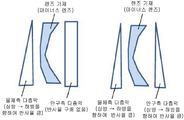
도 3 은 마이너스 렌즈인 렌즈 기재 양면에 배치하는 피막의 바람직한 조합을 나타내는 모식도이다.
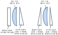
도 4 는 플러스 렌즈인 렌즈 기재 양면에 배치하는 피막의 바람직한 조합을 나타내는 모식도이다.
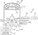
도 5 는 본 발명의 일 양태에 있어서 사용 가능한 증착 장치의 구성을 나타낸다.
도 6 은 실시예에서 사용한 메커니컬 마스크 (차폐 부재) 의 개략 평면도이다.
도 7 은 실시예 1 에 있어서 물체측 표면 상에 형성한 다층막에 포함되는 각 층의 피팅 포인트를 통과하는 직선 상의 7 점에 있어서의 각 층의 막두께 (물리 막두께 (단위:㎚)) 및 400 ∼ 500 ㎚ 의 파장역에 있어서의 직입사 평균 반사율을 나타낸다.
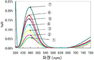
도 8 은 실시예 1 에서 제조한 안경 렌즈의 380 ∼ 780 ㎚ 의 파장역에 있어서의 분광 반사 스펙트럼 (직입사 반사 분광 특성) 이다.
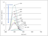
도 9 는 실시예 1 에서 제조한 안경 렌즈의 380 ∼ 780 ㎚ 의 파장역에 있어서의 분광 투과 스펙트럼 (직입사 투과 분광 특성) 이다.
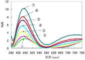
도 10 은 실시예 1 에서 제조한 안경 렌즈의 볼록면 상의 상기한 7 점으로부터 직입사하는 광의 1 회 다중 반사 스펙트럼을 나타낸다.
도 11 은 사람의 눈에 대한 표준 비시감도를 나타낸다.
도 12 는 도 10 에 나타내는 스펙트럼에, 도 11 에 나타내는 명소, 암소에서의 시감도를 곱하여 얻어진 스펙트럼이다.
도 13 은 도 9 에 나타내는 분광 투과 스펙트럼으로부터, Lab(CIE)2°, 광원을 CIE ― D65 로 하여 계산하여 얻은 투과광의 색도 좌표를 나타낸다.
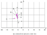
도 14 는 도 8 에 나타내는 분광 반사 스펙트럼으로부터, Lab(CIE)2°, 광원을 CIE ― D65 로 하여 계산하여 얻은 볼록면 (물체측 표면) 으로부터의 반사광의 색도 좌표를 나타낸다.1 is a schematic process diagram showing an example of a method of manufacturing a spectacle lens surface in which a lower region has reflection characteristics (1) and (2).
Fig. 2 is a schematic plan view of a multilayer film formed by a process shown schematically in Fig.
Fig. 3 is a schematic view showing a preferable combination of coatings arranged on both surfaces of a lens substrate which is a negative lens.
Fig. 4 is a schematic view showing a preferable combination of coatings arranged on both surfaces of a lens substrate which is a positive lens. Fig.
5 shows a configuration of a deposition apparatus usable in an embodiment of the present invention.
6 is a schematic plan view of a mechanical mask (shielding member) used in the embodiment.
7 is a graph showing the relationship between the film thickness (physical thickness (unit: nm)) of each layer at seven points on a straight line passing through the fitting points of the respective layers included in the multilayer film formed on the object- And the average reflectance of the incident light in a wavelength range of 400 to 500 nm.
8 is a spectral reflection spectrum (direct incident reflection spectroscopic characteristic) in the wavelength range of 380 to 780 nm of the spectacle lens manufactured in Example 1. Fig.
9 is a spectral transmittance spectrum (direct ray penetration spectroscopic characteristic) of the spectacle lens manufactured in Example 1 at a wavelength range of 380 to 780 nm.
10 shows a single multiple reflection spectrum of light incident directly on the convex surface of the spectacle lens manufactured in Example 1 at the above-mentioned seven points.
Figure 11 shows the standard viscous sensitivity to the human eye.
Fig. 12 is a spectrum obtained by multiplying the spectrum shown in Fig. 10 by the visibility in a place and a dark place shown in Fig.
Fig. 13 shows chromaticity coordinates of transmitted light obtained by calculating Lab (CIE) 2 deg. And light source CIE-D65 from the spectral transmittance spectrum shown in Fig.
14 shows the chromaticity coordinates of the reflected light from the convex surface (object side surface) obtained by calculating Lab (CIE) 2 deg. And the light source as CIE-D65 from the spectral reflection spectrum shown in Fig.
본 발명의 안경 렌즈는, 물체측 표면 및 안구측 표면의 적어도 일방의 표면이, 장용시에 피팅 포인트 또는 광학 중심보다 하방에 위치하는 하방 영역 (이하, 간단히「하방 영역」이라고도 한다) 에 있어서, 하기 (1) 및 (2) 를 만족시키는 반사 특성을 갖는다.In the spectacle lens of the present invention, at least one surface of the object-side surface and the eyeball-side surface is a lower region (hereinafter, simply referred to as a "lower region") located below the fitting point or the optical center at the time of wearing, (1) and (2) below.
(1) 400 ∼ 500 ㎚ 의 파장역에 있어서의 직입사 평균 반사율이 1.0 ∼ 15 % 의 범위인 것 ; 및(1) having an average direct reflectance of 1.0 to 15% in a wavelength range of 400 to 500 nm; and
(2) 상기 직입사 평균 반사율이, 장용시에 상기 하방 영역보다 상방에 위치하는 상방 영역 (이하, 간단히「상방 영역」이라고도 한다) 의 400 ∼ 500 ㎚ 의 파장역에 있어서의 직입사 평균 반사율을 초과하는 것.(2) The direct reflectance average reflectance of the direct incident average reflectance in a wavelength region of 400 to 500 nm of an upper region (hereinafter simply referred to as " upper region " Exceeding.
이하, 본 발명의 안경 렌즈에 대하여, 더욱 상세하게 설명한다.Hereinafter, the spectacle lens of the present invention will be described in more detail.
본 발명의 안경 렌즈는, 물체측 표면 및 안구측 표면의 적어도 일방의 표면에 있어서, 장용시에 피팅 포인트 또는 광학 중심보다 하방에 위치하는 하방 영역에 있어서, 반사 특성 (1) 및 (2) 를 갖는다.The spectacle lens of the present invention is characterized in that the reflection characteristics (1) and (2) are obtained in at least one surface of the object side surface and the eyeball side surface in a region below the fitting point or optical center, .
상기 하방 영역은, 청색광의 발광원을 볼 때에 주로 사용되는 영역이며, 이 영역에 반사 특성 (1) 을 부여함으로써, 청색광에 의한 눈으로의 부담을 경감시킬 수 있다. 단, 안경 렌즈 표면의 전체면에 일정하게 청색광 반사 특성을 부여한 경우에는, 앞서 기재한 고스트 발생에 의해 안경 렌즈의 장용감은 저하된다.The lower region is a region mainly used when viewing the light emitting source of blue light, and by applying the reflection characteristic (1) to this region, the burden on the eye due to blue light can be reduced. However, in the case where the blue light reflection characteristic is uniformly given to the entire surface of the spectacle lens, the gauze feeling of the spectacle lens is lowered due to the ghost occurrence described above.
그래서 본 발명에서는, 장용시에 상기 하방 영역보다 상방에 위치하는 상방 영역의 청색광 반사 특성을, 하방 영역보다 저감시키거나, 상방 영역에는 청색광 반사 특성을 부여하지 않는다. 태양광이나 실내광, 야간 조명 (가로등) 등의 안경 렌즈의 상부로부터 입사하는 광이 렌즈 내에서 다중 반사하는 것이 고스트의 주요한 발생 원인이기 때문에, 고스트는 안경 렌즈의 상방 영역을 사용하는 원방시에 있어서 주로 발생한다. 본 발명은, 이 점에 주목하여, 상방 영역보다 하방 영역에 선택적으로 청색광 반사 특성을 부여함으로써 (반사 특성 (2)), 청색광에 의한 눈으로의 부담의 경감과 양호한 장용감 (고스트의 저감 내지 방지) 의 양립을 가능하게 한 것이다.Therefore, in the present invention, the blue light reflection characteristic of the upper region located above the lower region at the time of wearing is lowered than the lower region, and the blue light reflection characteristic is not given to the upper region. Since ghost is a major cause of the reflection of light incident from above the spectacle lens such as sunlight, indoor light, night light (street lamp), etc. in the lens, . The present invention focuses attention on this point, and it is possible to reduce the burden on the eye by the blue light and improve the feeling of good intestine (the ghost is reduced or eliminated) by giving the blue light reflection characteristic selectively to the area below the upper area Prevention) can be made compatible with each other.
안경 렌즈 표면에 반사 특성 (1) 및 (2) 를 갖는 수단으로는, 안경 렌즈 표면의 적어도 하방 영역에 반사 특성 (1) 을 갖는 피막을 형성하는 방법, 청색광을 반사하는 성능을 갖는 첨가제를 안경 렌즈 표층부의 하방 영역에 국재시키는 방법 등을 들 수 있다. 원하는 반사 특성을 용이하게 부여하는 관점에서는, 피막에 의한 방법이 바람직하다. 통상적으로 소정의 파장역의 광을 선택적으로 반사하는 피막은, 광학막을 복수 적층함으로써 형성된다. 본 발명에서도, 이렇게 하여 형성되는 다층막에 의해, 반사 특성 (1) 및 (2) 를 실현할 수 있다. 즉, 본 발명의 바람직한 양태에 관련된 안경 렌즈는, 렌즈 기재 상에 직접 또는 간접적으로 다층막을 갖고, 그 다층막에 의해 반사 특성 (1) 및 (2) 가 부여되고 있다.Examples of the means having the reflection characteristics (1) and (2) on the surface of the spectacle lens include a method of forming a film having a reflection characteristic (1) in at least a lower region of the surface of the spectacle lens, A method in which the lens is localized in a region below the surface layer of the lens, and the like. From the viewpoint of easily imparting a desired reflection characteristic, a coating method is preferable. A film that selectively reflects light in a predetermined wavelength region is typically formed by laminating a plurality of optical films. Also in the present invention, the reflection characteristics (1) and (2) can be realized by the multilayer film formed in this manner. That is, the spectacle lens according to the preferred embodiment of the present invention has a multilayered film directly or indirectly on the lens substrate, and the multilayered film imparts reflection characteristics (1) and (2) thereto.
이하, 상기 다층막의 구체적 양태에 대해 설명한다. 단, 본 발명은 하기 구체적 양태에 한정되는 것은 아니고, 반사 특성 (1) 및 (2) 가 물체측 표면 및 안구측 표면의 적어도 일방의 표면에 부여되고 있는 안경 렌즈이면, 본 발명의 안경 렌즈에 포함된다.Hereinafter, a specific aspect of the multilayer film will be described. However, the present invention is not limited to the specific embodiments described below. If the spectacle lens in which the reflection characteristics (1) and (2) are provided on at least one surface of the object side surface and the eyeball side surface, .
렌즈 표면의 하방 영역에 반사 특성 (1) 의 청색광 반사 성능을 부여하기 위한 다층막은, 고굴절률층과 저굴절률층을 순차 적층함으로써 형성할 수 있다. 보다 상세하게는, 고굴절률층 및 저굴절률층을 형성하기 위한 막 재료의 굴절률과, 반사해야 할 광인 청색광의 파장에 기초하여, 공지된 수법에 의한 광학적 시뮬레이션에 의해 각 층의 막두께를 결정하고, 결정한 막두께가 되도록 정한 성막 조건하에서 고굴절률층과 저굴절률층을 순차 적층함으로써, 상기 다층막을 형성할 수 있다. 고굴절률층을 형성하기 위한 고굴절 재료로는, Ta2O5, ZrO2, TiO2, Al2O3, Y2O3, HfO2, 및 Nb2O5 로 이루어지는 군에서 선택되는 산화물을 들 수 있다. 한편, 저굴절률층을 형성하기 위한 저굴절률 재료로는 SiO2, MgF2 를 들 수 있다. 또한 여기서는, 편의상, 산화물 및 불화물을 화학량론 조성으로 표시하였지만, 화학량론 조성으로부터 산소 또는 불소가 결손되거나 혹은 과다한 상태에 있는 것도, 고굴절률 재료 또는 저굴절률 재료로서 사용 가능하다.The multilayer film for imparting the blue light reflection performance of the reflection characteristic (1) to the lower region of the lens surface can be formed by sequentially laminating the high refractive index layer and the low refractive index layer. More specifically, the film thickness of each layer is determined by optical simulation by a known technique based on the refractive index of the film material for forming the high refractive index layer and the low refractive index layer and the wavelength of the blue light which is the light to be reflected , And the multilayered film can be formed by sequentially laminating a high refractive index layer and a low refractive index layer under a film forming condition defined to be a predetermined film thickness. As the high refractive index material for forming the high refractive index layer, oxides selected from the group consisting of Ta 2 O 5 , ZrO 2 , TiO 2 , Al 2 O 3 , Y 2 O 3 , HfO 2 , and Nb 2 O 5 . On the other hand, SiO 2 and MgF 2 can be given as low refractive index materials for forming the low refractive index layer. Here, for convenience, oxides and fluorides are represented by the stoichiometric composition. However, oxygen or fluorine may be missing or excess from the stoichiometric composition may be used as a high refractive index material or a low refractive index material.
다층막에 포함되는 각 층의 막두께는, 상기 서술한 바와 같이, 광학적 시뮬레이션에 의해 결정할 수 있다. 다층막의 층 구성으로는, 예를 들어, 렌즈 기재측에서 렌즈 최표면측을 향하여,The film thickness of each layer included in the multilayer film can be determined by optical simulation as described above. As the layer structure of the multilayer film, for example, from the lens base side to the lens outermost surface side,
제 1 층 (저굴절률층)/제 2 층 (고굴절률층)/제 3 층 (저굴절률층)/제 4 층 (고굴절률층)/제 5 층 (저굴절률층)/제 6 층 (고굴절률층)/제 7 층 (저굴절률층) 의 순서로 적층된 구성 ;The first layer (low refractive index layer) / the second layer (high refractive index layer) / the third layer (low refractive index layer) / the fourth layer (high refractive index layer) / the fifth layer A refractive index layer) / a seventh layer (a low refractive index layer);
제 1 층 (고굴절률층)/제 2 층 (저굴절률층)/제 3 층 (고굴절률층)/제 4 층 (저굴절률층)/제 5 층 (고굴절률층)/제 6 층 (저굴절률층) 의 순서로 적층된 구성The first layer (high refractive index layer) / the second layer (low refractive index layer) / the third layer (high refractive index layer) / the fourth layer (low refractive index layer) / the fifth layer (high refractive index layer) / the sixth layer Refractive index layer)
등을 들 수 있다. 바람직하게는, 상기 각 층은, 전술한 고굴절률 재료 또는 저굴절률 재료를 주성분으로서 함유하는 증착원을 사용하는 증착에 의해 형성된다. 여기서 주성분이란, 증착원에 있어서 가장 대부분을 차지하는 성분으로서, 통상적으로는 전체의 50 질량% 정도 ∼ 100 질량%, 나아가서는 90 질량% 정도 ∼ 100 질량% 를 차지하는 성분이다. 또한 증착원에는, 불가피적으로 혼입되는 미량의 불순물이 함유되는 경우가 있고, 또, 주성분이 하는 기능을 저해하지 않는 범위에서 다른 성분, 예를 들어 다른 무기 물질이나 증착을 보조하는 역할을 하는 공지된 첨가 성분이 함유되어 있어도 된다. 또, 본 발명에 있어서의 증착에는, 건식법, 예를 들어, 진공 증착법, 이온 플레이팅법, 스퍼터링법 등이 포함된다. 진공 증착법에서는, 증착 중에 이온빔을 동시에 조사하는 이온빔 어시스트법을 사용해도 된다.And the like. Preferably, each of the layers is formed by vapor deposition using an evaporation source containing the above-mentioned high refractive index material or a low refractive index material as a main component. Here, the main component is a component which occupies the most part in the evaporation source, and is usually a component which accounts for about 50% by mass to 100% by mass, and more preferably about 90% by mass to 100% by mass. In addition, the evaporation source may contain a small amount of impurities inevitably incorporated, and may contain other components, for example, other inorganic substances or a function that assists deposition, within a range that does not impair the function of the main component May be contained. Incidentally, the deposition in the present invention includes a dry method, for example, a vacuum deposition method, an ion plating method, a sputtering method, and the like. In the vacuum deposition method, an ion beam assist method in which an ion beam is simultaneously irradiated during deposition may be used.
상기 다층막은, 이상 설명한 고굴절률층 및 저굴절률층에 추가하여, 도전성 산화물을 주성분으로 하는 증착원을 사용하는 증착에 의해 형성되는 1 층 이상의 도전성 산화물층을 다층막의 임의의 위치에 포함할 수도 있다. 도전성 산화물로는, 안경 렌즈의 투명성을 저하시키지 않도록, 투명 도전성 산화물로서 알려진 산화인듐, 산화주석, 산화아연, 티타니아 및 이것들의 복합 산화물을 사용하는 것이 바람직하다. 투명성 및 도전성의 관점에서 특히 바람직한 도전성 산화물로는, 인듐-주석 산화물 (ITO) 을 들 수 있다. 도전성 산화물층을 포함함으로써, 안경 렌즈가 대전되어 티끌이나 먼지가 부착되는 것을 방지할 수 있다.In addition to the high refractive index layer and the low refractive index layer described above, the multilayered film may include at least one conductive oxide layer formed by vapor deposition using an evaporation source containing a conductive oxide as a main component at an optional position of the multilayered film . As the conductive oxide, it is preferable to use indium oxide, tin oxide, zinc oxide, titania, or a composite oxide thereof known as a transparent conductive oxide so as not to lower the transparency of the spectacle lens. A particularly preferable conductive oxide from the viewpoints of transparency and conductivity is indium-tin oxide (ITO). By including the conductive oxide layer, it is possible to prevent dust or glasses from adhering to the spectacle lens.
본 발명의 안경 렌즈는, 물체측 표면 및 안구측 표면의 적어도 일방의 표면의 하방 영역이 반사 특성 (1) 을 갖는다. 안경 장용자가 청색광의 발광원을 볼 때에 주로 사용하는 영역인 하방 영역에 있어서, 400 ∼ 500 ㎚ 의 파장역에 있어서의 직입사 평균 반사율이 1.0 % 이상임으로써, 청색광에 의한 눈으로의 부담을 경감시킬 수 있다. 한편, 청색광 반사 특성을 높게 할수록 청색광에 의한 눈으로의 부담을 경감시킬 수 있지만, 높게 할수록 안경 렌즈의, 특히 물체측 표면으로부터의 반사광이 안경 렌즈의 외관을 변화시킨다 (간섭색의 발생). 또, 장용자가, 특히 안구측으로부터 입사되는 청색광이 반사된 반사광 (후방으로부터 입사한 광의 복귀광) 에 의한 눈부심을 느끼게 된다. 상기의 직입사 평균 반사율이 15 % 이하이면, 그러한 영향은 작기 때문에, 본 발명의 안경 렌즈에 있어서, 상기의 직입사 평균 반사율은 15 % 이하로 한다. 바람직하게는 10 % 이하이다. 또한 하방 영역에 있어서 400 ∼ 500 ㎚ 의 파장역에 있어서의 직입사 평균 반사율이 상기 범위 내에 있다는 것은, 하방 영역의 1 점 이상에서 측정되는 400 ∼ 500 ㎚ 의 파장역에 있어서의 직입사 평균 반사율이 상기 범위 내에 있는 것을 말하고, 바람직하게는 2 점 이상 (예를 들어 2 ∼ 10 점) 에서 측정되는 400 ∼ 500 ㎚ 의 파장역에 있어서의 직입사 평균 반사율이 상기 범위 내에 있는 것을 말한다.In the spectacle lens of the present invention, a region below at least one surface of the object side surface and the eyeball side surface has a reflection characteristic (1). The average direct reflectance of the observer at a wavelength range of 400 to 500 nm is 1.0% or more in the lower region, which is the area mainly used when the spectacle wearer watches the blue light emission source, thereby reducing the burden on the eye due to the blue light . On the other hand, the higher the blue light reflection characteristic, the less the burden on the eye due to the blue light. However, the higher the degree, the more the reflected light from the object side surface of the spectacle lens changes the appearance of the spectacle lens. In addition, the wearer feels glare due to reflected light (return light of light incident from the rear), in particular, blue light incident from the eyeball side. When the average direct reflectance of the spectacle lens of the present invention is 15% or less, the direct reflectance average reflectance is 15% or less. And preferably not more than 10%. The reason why the average direct reflectance of the direct incident light in the wavelength region of 400 to 500 nm in the lower region is within the above range is that the average direct reflectance of the incident light in the wavelength region of 400 to 500 nm measured at one or more points of the lower region Means that the average direct reflectance at a wavelength range of 400 to 500 nm measured at two or more points (for example, 2 to 10 points) is within the above range.
이상 설명한 바와 같이, 본 발명의 안경 렌즈의 물체측 표면 및 안구측 표면의 적어도 일방의 표면은, 하방 영역에 있어서, 반사 특성 (1) 의 청색광 반사 특성을 갖는다. 이것에 더하여 상방 영역에 있어서 청색광 반사 특성을 저감시키거나, 상방 영역에 청색광 반사 특성을 부여하지 않음으로써, 물체측 표면 및 안구측 표면의 적어도 일방의 표면에 있어서, 하방 영역이 반사 특성 (1) 및 (2) 를 만족시키는 것이 된다. 본 발명의 안경 렌즈에서는, 반사 특성 (1) 및 (2) 를 갖는 표면에 있어서, 하방 영역에 선택적으로 청색광 반사 특성을 부여하는 관점에서는, 하방 영역의 400 ∼ 500 ㎚ 의 파장역에 있어서의 직입사 평균 반사율과 상방 영역의 직입사 평균 반사율의 차분 [(하방 영역의 직입사 평균 반사율) ― (상방 영역의 직입사 평균 반사율)] 은 2 % 이상인 것이 바람직하고, 양 영역의 반사 특성의 차가 안경 렌즈의 외관 및 장용감에 크게 영향을 미치는 것을 방지하는 관점에서는 14 % 이하인 것이 바람직하다. 또, 상기 차분이란, 하방 영역에 있어서 측정된 직입사 평균 반사율의 평균값과 상방 영역에 있어서 측정된 직입사 평균 반사율의 평균값의 차분이어도 된다. 또는, 하방 영역에 있어서 측정된 직입사 평균 반사율의 최대값과 상방 영역에 있어서 측정된 직입사 평균 반사율의 최소값의 차분이어도 된다.As described above, at least one surface of the object side surface and the eyeball side surface of the spectacle lens of the present invention has the blue light reflection characteristic of the reflection characteristic (1) in the lower region. In addition, by suppressing the blue light reflection characteristic in the upper region or not imparting the blue light reflection characteristic in the upper region, it is possible to suppress the reflection characteristic (1) in at least one surface of the object side surface and the eye- And (2). In the spectacle lens of the present invention, from the viewpoint of selectively imparting the blue light reflection characteristic to the lower region on the surface having the reflection characteristics (1) and (2), the The difference between the incidence average reflectance and the direct incident average reflectance in the upper region (the average reflectance of the direct incident light in the lower region) - (the average reflectance of the incident light in the upper region)) is preferably 2% or more, But it is preferably 14% or less from the viewpoint of preventing the lens from significantly affecting appearance and long-lasting feeling. The difference may be a difference between an average value of the direct incident average reflectance measured in the lower region and an average value of the direct incident average reflectance measured in the upper region. Alternatively, it may be a difference between the maximum value of the direct incident average reflectance measured in the lower region and the minimum value of the direct incident average reflectance measured in the upper region.
상방 영역에 청색광 반사 특성을 부여하지 않기 위해서는, 증착시에 상방 영역 표면을 테이프를 첩부 (貼付) 하거나 하여 마스킹함으로써, 당해 영역에 증착 재료가 퇴적되는 것을 막으면 된다. 단, 이렇게 하여 형성된 안경 렌즈는, 안경 장용자 및 장용자와 대향하는 제삼자 모두, 상방 영역과 하방 영역의 경계가 선명히 시인되는 경향이 있다. 이것은 외관상 바람직하지 않기 때문에 상기 서술한 반사 특성 (1) 및 (2) 를 갖는 안경 렌즈 표면은, 상방 영역에서 하방 영역을 향하여, 400 ∼ 500 ㎚ 의 파장역에 있어서의 직입사 평균 반사율이 연속적 내지 단계적으로 증가하는 반사 특성 (반사율 구배) 을 갖는 것이 바람직하다.In order not to impart the blue light reflection characteristic to the upper region, it is preferable to prevent the deposition material from being deposited on the upper region by masking the upper region surface with a tape. However, in the spectacle lens thus formed, the boundary between the upper region and the lower region tends to be clearly visible in both the glasses holder and the third person facing the user. The spectacle lens surface having the above-described reflection characteristics (1) and (2) has an average direct reflectance at a wavelength range of 400 to 500 nm from the upper region toward the lower region, It is preferable to have a stepwise increasing reflection characteristic (reflectance gradient).
안경 렌즈 표면에 반사율 구배를 갖게 하기 위해서는, 다층막을 형성하는 증착 공정에 있어서, 적어도 1 층의 증착막을 형성할 때, 안경 렌즈의 피증착면의 장용시에 상방 영역 또는 하방 영역이 되는 부분의 상방에 차폐 부재를 배치하는 것이 바람직하다. 이로써, 상방에 차폐 부재가 배치된 부분으로의 증착 재료의 퇴적량이 다른 부분보다 적어지기 때문에, 당해 공정에서 형성되는 증착막의 막두께를, 장용시에 상방에 위치하는 부분에서 하방에 위치하는 부분을 향하여 연속적 내지 단계적으로 변화시킬 수 있다. 이하, 이와 같은 증착 공정의 일 양태를, 도면에 기초하여 설명한다.In order to have a reflectance gradient on the surface of the spectacle lens, it is preferable that at least one layer of vapor deposition film is formed in the vapor deposition step of forming a multilayer film, It is preferable to dispose the shielding member. As a result, the deposition amount of the evaporation material to the portion where the shielding member is disposed above is smaller than that of the other portions. Therefore, the film thickness of the evaporation deposition film formed in the above process can be set so that the portion located below And can be changed continuously or stepwise. Hereinafter, one embodiment of such a deposition process will be described with reference to the drawings.
도 1 은 하방 영역이 반사 특성 (1) 및 (2) 를 갖는 안경 렌즈 표면의 제조 방법의 일례를 나타내는 개략 공정도이다. 도면 중, 안경 렌즈 기재를 평면 렌즈로서 도시하고 있지만, 본 발명에 있어서의 안경 렌즈 기재는 양면 평면인 것에 한정되는 것은 아니다. 이 점에 대해서는 후술한다. 또, 도면 중, 안경 렌즈 기재의 하방에 증착원을 배치하고 상방의 안경 렌즈 기재 표면을 향하여 증착 재료를 증발시키는 양태를 나타내고 있지만, 안경 렌즈 기재와 증착 재료의 배치는 이 반대여도 된다.1 is a schematic process diagram showing an example of a method of manufacturing a spectacle lens surface in which a lower region has reflection characteristics (1) and (2). In the drawings, the spectacle lens base material is shown as a planar lens, but the spectacle lens base material in the present invention is not limited to a two-sided plane. This point will be described later. In the drawings, an evaporation source is disposed below the spectacle lens base material and the evaporation material is evaporated toward the upper surface of the spectacle lens base material. However, the arrangement of the spectacle lens base material and the evaporation material may be reversed.
먼저, 렌즈 기재의 피증착면을 증착원측을 향하게 하여, 렌즈 기재를 증착 장치에 배치한다. 증착 장치로는, 공지된 증착 장치를 사용할 수 있다. 본 발명에 있어서 사용 가능한 증착 장치의 일례에 대해서는, 후술하는 실시예에 있어서 설명한다.First, the lens substrate is placed in the evaporation apparatus with the evaporated surface of the lens substrate facing the evaporation source side. As the deposition apparatus, a known deposition apparatus can be used. An example of a deposition apparatus usable in the present invention will be described in the following embodiments.
증착 장치 내에서, 면내에서 막두께를 변화시켜야 할 증착막을 형성할 때, 렌즈 기재의 피증착면과 증착원 사이의 상기 상방 영역 또는 하방 영역에 상당하는 부분의 상방에 차폐 부재를 배치한다 (도 1 의 (a)). 여기서 차폐 부재는, 렌즈 기재의 피증착면에 밀착시키지 않고, 공간을 형성하여 배치한다. 이 상태에서 하방으로부터 증착 재료가 증발하면, 렌즈 기재의 피증착면에서는, 상방에 차폐 부재가 없는 부분에 다량의 증착 재료가 퇴적되고, 상방에 차폐 부재가 있는 부분에서는, 상방에 차폐 부재가 없는 부분과의 경계 부근에는 약간량의 증착 재료가 퇴적되고, 경계로부터 멀어질수록 퇴적량이 적어진다 (도 1 의 (b)). 이렇게 하여, 장용시에 상방에 위치하는 부분에서 하방에 위치하는 부분을 향하여 연속적 내지 단계적으로 막두께가 변화하는 증착막을 형성할 수 있다. 그 후, 차폐 부재를 제거하고 (도 1 의 (c)), 증착 공정을 반복함으로써, 렌즈 기재의 피증착면 상에 다층막을 형성할 수 있다 (도 1 의 (d), (e)). 이렇게 하여 형성된 다층막의 개략 평면도를 도 2 에 나타낸다. 또한 면내에서 막두께가 상이한 증착막은, 다층막에 적어도 1 층 형성할 수 있고, 2 층 이상 형성하는 것도 가능하다. 예를 들어, 일 양태에서는, 저굴절률층의 막두께를 얇게 할수록 청색광 반사 특성은 저하되고, 고굴절률층의 막두께를 두껍게 할수록 청색광 반사 특성은 높아진다. 이 경우에는, 저굴절률층의 막두께를 하방 영역에 있어서 상방 영역보다 두껍게 함으로써, 또는 고굴절률층의 막두께를 하방 영역에 있어서 상방 영역보다 얇게 함으로써, 하방 영역의 청색광 반사 특성을 상방 영역보다 높일 수 있다. 또 반대로, 저굴절률층의 막두께를 얇게 할수록 청색광 반사 특성이 높아지고, 고굴절률층의 막두께를 두껍게 할수록 청색광 반사 특성이 저하되는 양태에 대해서는, 상기와 반대로 함으로써, 하방 영역의 청색광 반사 특성을 상방 영역보다 높일 수 있다.A shielding member is disposed above a portion corresponding to the upper region or the lower region between the evaporation source of the lens base and the evaporation source when a vapor deposition film whose film thickness is to be changed in the plane in the evaporation apparatus is formed 1 (a)). Here, the shielding member is formed so as not to be in close contact with the evaporated deposition surface of the lens base, but by forming a space therebetween. When the evaporation material evaporates from below in this state, a large amount of evaporation material is deposited on the evaporation surface of the lens substrate above the portion where the shielding member is absent, and in the portion above the shielding member, A small amount of evaporation material is deposited near the boundary with the portion, and the deposition amount decreases as the distance from the boundary increases (Fig. 1 (b)). In this manner, a vapor-deposited film whose film thickness changes continuously or stepwise from a portion located above in the case of wearing to a portion located in the lower side can be formed. Thereafter, the multilayer film can be formed on the evaporated surface of the lens substrate by removing the shielding member (Fig. 1 (c)) and repeating the evaporation process (Fig. 1 (d), (e)). A schematic plan view of the multi-layered film thus formed is shown in Fig. Also, at least one vapor-deposited film having a different film thickness in the plane may be formed in the multilayer film, or two or more vapor-deposited films may be formed. For example, in one embodiment, the blue light reflection characteristic decreases as the film thickness of the low refractive index layer is made thinner, and the blue light reflection characteristic becomes higher as the film thickness of the high refractive index layer becomes thicker. In this case, by making the film thickness of the low refractive index layer thicker than the upper region in the lower region or making the film thickness of the high refractive index layer thinner than the upper region in the lower region, the blue light reflection characteristic of the lower region is made higher than the upper region . Conversely, by reversing the above-described manner in which the blue light reflection characteristic is increased as the film thickness of the low refractive index layer is made thinner and the blue light reflection characteristic is lowered as the film thickness of the high refractive index layer is made thicker, Region.
또한, 다층막을 형성하기 위한 복수 회의 증착 공정의 중간 공정에 있어서, 차폐 부재의 배치 및 분리를 실시하는 것은, 제조 공정이 번잡해진다. 따라서, 공정 간략화의 관점에서는, 차폐 부재를 배치하여 실시하는 증착 공정은, 복수 회의 증착 공정의 최초의 공정 또는 최후의 공정으로 하는 것, 즉 다층막의 제 1 층 또는 최상층을 형성하는 공정으로 하는 것이 바람직하다.Further, in the intermediate process of the vapor deposition process for forming a multi-layer film, arranging and separating the shield members makes the manufacturing process complicated. Therefore, from the viewpoint of simplification of the process, the vapor deposition process in which the shielding member is disposed is performed in the first process or the last process of a plurality of vapor deposition processes, that is, the process of forming the first layer or the uppermost layer of the multilayer film desirable.
이상 설명한 바와 같이, 본 발명에 의하면, As described above, according to the present invention,
렌즈 기재 상에 직접 또는 간접적으로 다층막을 갖고, 그 다층막에 의해 상기 반사 특성이 부여되고 있는 본 발명의 안경 렌즈의 제조 방법도 제공된다.There is also provided a method of manufacturing a spectacle lens of the present invention having a multilayered film directly or indirectly on a lens substrate and having the above-mentioned reflection characteristic imparted by the multilayered film.
상기 제조 방법은, 렌즈 기재 상의 피증착면에 증착 재료를 퇴적시키는 증착 공정을 복수 회 반복함으로써 상기 다층 증착막을 형성하는 것을 포함하고, 상기 복수 회의 증착 공정의 적어도 일 공정에 있어서, 피증착면의 상기 상방 영역 또는 하방 영역에 상당하는 부분의 상방에 차폐 부재를 배치함으로써, 그 부분으로의 증착 재료의 퇴적량을 저감시킨다. 이렇게 하여, 물체측 표면 및 안구측 표면의 적어도 일방의 표면의 하방 영역이 반사 특성 (1) 및 (2) 를 갖는 안경 렌즈를 얻을 수 있다.The manufacturing method includes forming the multilayer evaporation film by repeating a deposition process for depositing an evaporation material on a deposition surface on a lens substrate a plurality of times, wherein in at least one step of the plurality of evaporation processes, By disposing the shielding member above the portion corresponding to the upper region or the lower region, the accumulation amount of the evaporation material on the portion is reduced. Thus, the spectacle lens having the reflection characteristics (1) and (2) below the surface of at least one of the object-side surface and the eyeball-side surface can be obtained.
본 발명의 안경 렌즈에 있어서, 하방 영역이 반사 특성 (1) 및 (2) 를 갖는 표면은, 물체측 표면, 안구측 표면 중 어느 일방만 일 수 있고 또는 양면일 수도 있다. 렌즈 기재가 중심부 두께가 주변부 두께보다 얇은 마이너스 렌즈인 경우에는, 적어도 물체측 표면이 하방 영역이 반사 특성 (1) 및 (2) 를 갖는 표면인 것이 바람직하다. 한편, 렌즈 기재가 중심부 두께가 주변부 두께보다 두꺼운 플러스 렌즈인 경우에는, 적어도 안구측 표면이 하방 영역이 반사 특성 (1) 및 (2) 를 갖는 표면인 것이 바람직하다. 이것은, 렌즈의 형상상, 마이너스 렌즈에 있어서는, 장용자의 후방 상부로부터 안구측 표면에 입사된 광이 물체측 표면에서 반사되어 복귀광이 되어 장용자의 눈에 입사되는 양이 많아지는 경향이 있기 때문에, 물체측 표면의 상방 영역의 청색광 반사 특성을 낮게 하여 복귀광의 발생을 방지해야 하기 때문이다. 한편, 렌즈의 형상상, 플러스 렌즈에 있어서는, 장용자의 상부 후방으로부터 안구측 표면에 입사한 광이 동표면에서 반사되어 장용자의 눈에 입사되는 양이 많아지는 경향이 있기 때문에, 안구측 표면의 상방 영역의 청색광 반사 특성을 낮게 하여 안구측 표면 상방 영역에서의 반사광의 발생을 방지해야 하기 때문이다.In the spectacle lens of the present invention, the surface in which the lower region has the reflection characteristics (1) and (2) may be either the object side surface or the eyeball side surface or may be both surfaces. When the lens base material is a negative lens whose central portion thickness is thinner than the peripheral portion thickness, it is preferable that at least the object side surface is a surface having the reflection characteristics (1) and (2). On the other hand, when the lens base material is a positive lens whose central portion thickness is thicker than the peripheral portion thickness, it is preferable that at least the eyeball side surface is a surface having the reflection characteristics (1) and (2). This is because the amount of light incident on the eyeball side surface from the rear upper portion of the wearer is reflected by the object side surface to be returned light and is incident on the eye of the wearer tends to increase in the shape of the lens and the negative lens, It is necessary to lower the blue light reflection characteristic of the upper region of the object side surface to prevent the generation of returned light. On the other hand, in the shape of the lens and the positive lens, since the light incident on the eyeball side surface from the upper back of the wearer tends to be reflected on the surface of the wearer to be incident on the eyes of the wearer, It is necessary to lower the blue light reflection characteristic of the region to prevent the generation of reflected light in the region above the eyeball side surface.
어떤 경우도, 타방의 면에는 청색광 반사 특성을 부여해도 되고, 하지 않아도 된다. 타방의 면에 청색광 반사 특성을 부여하는 경우, 타방의 면도 동일하게 하방 영역이 반사 특성 (1) 및 (2) 를 갖는 표면이어도 되고, 타방의 면은 400 ∼ 500 ㎚ 의 파장역에 있어서의 직입사 평균 반사율이 상방 영역, 하방 영역에서 변화하지 않는 (반사율 구배가 없는) 표면이어도 된다. 이상의 양태를, 모식적으로 도 3 (마이너스 렌즈) 및 도 4 (플러스 렌즈) 에 나타낸다. 또한 렌즈 표면 전체면에 걸쳐서 일정한 조건으로 성막했다고 해도, 렌즈의 표면 형상 등의 영향에 의해 면내에서 ±1 % 의 반사율차는 발생하기 때문에, 상기의 반사율 구배가 없는 표면이란, 면내에서 ±1 % 의 반사율차를 갖는 표면을 포함하는 것으로 한다. 반사율 구배가 없는 표면의 400 ∼ 500 ㎚ 의 파장역에 있어서의 직입사 평균 반사율 (청색광 반사 특성) 은, 타방의 표면의 하방 영역의 청색광 반사 특성보다 낮은 것이 바람직하다. 타방의 면의 상방 영역의 청색광 반사 특성을 낮게 하는 (또는 부여하지 않는) 것에 의한 효과를, 보다 효과적으로 얻기 위해서이다. 한편, 렌즈 양면에 청색광 반사 특성을 분산 부여하는 것은, 각종 방향으로부터 렌즈에 입사되는 청색광이 눈에 입사하는 것을 방지하는 데에 있어서 유효하다. 따라서, 반사율 구배가 없는 표면에도, 청색광 반사 특성을 부여하는 것이 바람직하다. 고스트 억제의 관점에서는, 반사율 구배가 없는 표면의 청색광 반사 특성 (400 ∼ 500 ㎚ 의 파장역에 있어서의 직입사 평균 반사율) 은, 타방의 면의 상방 영역과 동일하거나 또는 그것 이하인 것이 바람직하다. 이러한 청색광 반사 특성은, 바람직하게는 렌즈 기재 상으로의 피막 형성, 보다 바람직하게는 다층막 형성에 의해, 렌즈의 일방의 면에 부여할 수 있다. 여기서 형성되는 다층막의 형성 방법에 대해서는, 전술한 기재를 참조할 수 있다. 막두께 분포를 갖게 하지 않고 다층막을 형성함으로써, 반사율 구배가 없는 청색 반사 특성을 갖는 표면을 얻을 수 있다.In either case, the blue light reflection characteristic may or may not be imparted to the other surface. In the case where the blue light reflection characteristic is imparted to the other surface, the other surface may also be a surface having the reflection characteristics (1) and (2) in the lower region and the other surface may be a surface in the wavelength region of 400 to 500 nm The incident average reflectance may be a surface that does not change in the upper and lower regions (there is no reflectance gradient). The above embodiment is schematically shown in Fig. 3 (negative lens) and Fig. 4 (positive lens). Even if a film is formed over the entire surface of the lens surface, a difference of reflectance of +/- 1% occurs in the surface due to the influence of the surface shape of the lens or the like. And a surface having a reflectance difference. It is preferable that the average direct reflectance (blue light reflection characteristic) of a surface having no reflectance gradient in a wavelength range of 400 to 500 nm is lower than a blue light reflection characteristic of a region below the other surface. In order to more effectively obtain the effect of lowering (or not giving) the blue light reflection characteristic of the upper region of the other surface. On the other hand, imparting the blue light reflection characteristic to both surfaces of the lens is effective in preventing blue light incident on the lens from various directions from entering the eye. Therefore, it is preferable to impart a blue light reflection characteristic to a surface having no reflectance gradient. From the viewpoint of ghost suppression, it is preferable that the blue light reflection characteristic (average direct reflectance of the incident light in the wavelength range of 400 to 500 nm) of the surface having no reflectance gradient is equal to or lower than the upper region of the other surface. Such a blue light reflection characteristic can be imparted to one surface of the lens, preferably by formation of a film on a lens substrate, more preferably by formation of a multilayer film. As for the method for forming the multilayer film formed here, the above-mentioned description can be referred to. By forming the multilayer film without having a film thickness distribution, a surface having a blue reflection characteristic without a reflectance gradient can be obtained.
이상 설명한 다층막은, 렌즈 기재 표면에 직접 형성해도 되고, 한층 이상의 기능성 막을 개재하여 렌즈 기재 상에 간접적으로 형성해도 된다. 렌즈 기재는, 특별히 한정되지 않지만, (메트)아크릴 수지를 비롯한 스티렌 수지, 폴리카보네이트 수지, 알릴 수지, 디에틸렌글리콜비스알릴카보네이트 수지 (CR-39) 등의 알릴카보네이트 수지, 비닐 수지, 폴리에스테르 수지, 폴리에테르 수지, 이소시아네이트 화합물과 디에틸렌글리콜 등의 하이드록시 화합물과의 반응으로 얻어진 우레탄 수지, 이소시아네이트 화합물과 폴리티올 화합물을 반응시킨 티오우레탄 수지, 분자 내에 1 개 이상의 디술파이드 결합을 갖는 (티오)에폭시 화합물을 함유하는 중합성 조성물을 경화하여 얻어지는 투명 수지 등을 들 수 있다. 또, 무기 유리도 사용 가능하다. 렌즈 기재의 굴절률은, 예를 들어 1.60 ∼ 1.75 정도이다. 단 렌즈 기재의 굴절률은, 이것에 한정되는 것은 아니고, 상기의 범위 내에서도, 상기의 범위로부터 상하로 떨어져 있어도 된다.The multi-layered film described above may be formed directly on the surface of the lens base material, or may be formed indirectly on the lens base material with a functional film of more than one layer interposed therebetween. The lens base material is not particularly limited, and examples thereof include allyl carbonate resins such as styrene resins, (meth) acrylic resins, polycarbonate resins, allyl resins and diethylene glycol bisallylcarbonate resins (CR-39), vinyl resins, A urethane resin obtained by reacting an isocyanate compound with a hydroxy compound such as diethylene glycol, a thiourethane resin obtained by reacting an isocyanate compound with a polythiol compound, a (thio) urethane resin having at least one disulfide bond in the molecule, And a transparent resin obtained by curing a polymerizable composition containing an epoxy compound. Inorganic glass can also be used. The refractive index of the lens base material is, for example, about 1.60 to 1.75. However, the refractive index of the lens base material is not limited to this, and the refractive index may be spaced up and down from the above range even within the above range.
본 발명의 안경 렌즈는, 단초점 렌즈, 다초점 렌즈, 누진 굴절력 렌즈 등의 각종 렌즈일 수 있다. 렌즈의 종류는, 렌즈 기재의 양면의 면 형상에 의해 결정된다. 예를 들어 누진 굴절력 렌즈에 대해서는, 통상적으로 근용부 (近用部) 영역 (근용부) 및 누진부 영역 (중간 영역) 이 전술한 하방 영역에 포함되고, 원용부 (遠用部) 영역 (원용부) 이 상방 영역에 포함된다. 또, 렌즈 기재 표면은, 볼록면, 오목면, 평면 중 어느 것이어도 된다. 통상적인 렌즈 기재에서는, 물체측 표면은 볼록면, 안구측 표면은 오목면이다. 단, 본 발명에 있어서 사용하는 렌즈 기재는 이것에 한정되는 것은 아니다.The spectacle lens of the present invention may be various lenses such as a short focal lens, a multifocal lens, and a progressive-power lens. The type of lens is determined by the surface shape of both surfaces of the lens base. For example, for a progressive-power lens, usually, a near region (near portion) and a progressive region (middle region) are included in the above-described lower region and a far- Is included in the upper region. The surface of the lens base material may be convex, concave, or planar. In a typical lens base material, the object-side surface is a convex surface and the eyeball-side surface is a concave surface. However, the lens base used in the present invention is not limited to this.
렌즈 기재와 다층막 사이에 형성될 수 있는 기능성 막으로는, 하드 코트층을 들 수 있다. 하드 코트층을 형성함으로써, 안경 렌즈에 방상성 (防傷性) (내찰상성) 을 부여할 수 있고, 또 안경 렌즈의 내구성 (강도) 을 높일 수도 있다. 하드 코트층의 상세한 내용에 대해서는, 예를 들어 일본 공개특허공보 2012-128135호 단락 0025 ∼ 0028, 0030 을 참조할 수 있다. 또, 기능성 막으로는, 밀착성 향상을 위한 프라이머층을 형성해도 된다. 프라이머층의 상세한 내용에 대해서는, 예를 들어 일본 공개특허공보 2012-128135호 단락 0029 ∼ 0030 을 참조할 수 있다.The functional film that can be formed between the lens substrate and the multilayer film includes a hard coat layer. By forming the hard coat layer, the spectacle lens can be provided with scratch resistance (scratch resistance), and the durability (strength) of the spectacle lens can be increased. For details of the hard coat layer, see, for example, Japanese Unexamined Patent Application Publication No. 2012-128135, paragraphs 0025 to 0028, 0030. As the functional film, a primer layer for improving the adhesion may be formed. For details of the primer layer, reference can be made, for example, to JP-A-2002-128135, paragraphs 0029 to 0030.
또한, 다층막상에 추가적인 기능성 막을 형성하는 것도 가능하다. 그러한 기능성 막으로는, 발수성 또는 친수성의 방오층을 들 수 있다. 그 상세한 내용에 대해서는, 일본 공개특허공보 2012-128135호 단락 0040 ∼ 0042 를 참조할 수 있다.It is also possible to form an additional functional film on the multilayer film. Examples of such a functional film include a water repellent layer or a hydrophilic layer having hydrophilic properties. For details, refer to Japanese Patent Laid-Open Publication No. 2012-128135, paragraphs 0040 to 0042.
이상 설명한 본 발명의 안경 렌즈는, 눈에 부담을 가하는 청색광이 눈에 입사되는 것을 효과적으로 억제할 수 있음과 함께, 원방시에 있어서의 고스트 발생이 저감되기 때문에 장용감이 양호하다.The spectacle lens of the present invention described above can effectively suppress the incidence of the blue light that imposes the burden on the eye, and also reduces the occurrence of ghost in the far field, so that the feeling of intestinal comfort is good.
실시예Example
이하, 본 발명을 실시예에 의해 더욱 설명하지만, 본 발명은 실시예에 나타내는 양태에 한정되는 것은 아니다.Hereinafter, the present invention will be further described by way of examples, but the present invention is not limited to the embodiments shown in the examples.
[실시예 1] [Example 1]
1-1. 렌즈 기재의 선택 및 하드 코트층의 성막1-1. Selection of lens substrate and deposition of hard coat layer
렌즈 기재로는, 마이너스 렌즈 (누진 굴절력 렌즈) 인 굴절률 1.67 의 안경용 플라스틱 렌즈 기재 (상품명 : 세이코 슈퍼 소브린 (SSV) (HOYA (주) 제조)) 를 사용하였다.As the lens base material, a plastic lens base material (trade name: Seiko Super Sovereign (SSV) (Hoya Co., Ltd.)) having a refractive index of 1.67, which is a negative lens (progressive power lens), was used.
하드 코트층을 형성하기 위한 도포액 (코팅액) 을 다음과 같이 조제하였다. 에폭시 수지-실리카하이브리드 (상품명 : 콤포세란 E102 (아라카와 화학 공업 (주) 제조)) 20 질량부에 산 무수물계 경화제 (상품명 : 경화제 액 (C2) (아라카와 화학 공업 (주) 제조)) 4.46 질량부를 혼합, 교반하여, 도포액을 얻었다. 이 도포액을 소정 두께가 되도록 스핀 코터를 사용하여 렌즈 기재의 물체측 표면, 안구측 표면의 각 면 상에 도포하였다. 도포 후의 렌즈 기재를 125 ℃ 에서 2 시간 소성하고, 실리카 및 티타니아 졸을 수지로 굳힌 타입의 층두께가 1000 ㎚ ∼ 3000 ㎚ 인 하드 코트층을 성막하였다.A coating liquid (coating liquid) for forming a hard coat layer was prepared as follows. 4.46 parts by mass of an acid anhydride-based curing agent (trade name: Curing agent liquid (C2) (Arakawa Chemical Industry Co., Ltd.)) was added to 20 parts by mass of an epoxy resin-silica hybrid (trade name: COMPOSTERAN E102 (Arakawa Chemical Industry Co., Followed by mixing and stirring to obtain a coating liquid. This coating liquid was coated on each of the object side surface and the eyeball side surface of the lens base material using a spin coater so as to have a predetermined thickness. The coated lens base was fired at 125 캜 for 2 hours to form a hard coat layer having a layer thickness of 1000 nm to 3000 nm of a hardened silica and titania sol resin.
이하에 있어서, 상기에 있어서 양면에 하드 코트층이 형성된 렌즈 기재를 렌즈 샘플이라고도 부른다.Hereinafter, the lens substrate on which the hard coat layer is formed on both surfaces is referred to as a lens sample.
1-2. 물체측 표면, 안구측 표면으로의 다층막의 성막1-2. Film formation on the object side surface and the eyeball side surface
도 5 에 나타내는 증착 장치를 사용하여, 물체측 표면, 안구측 표면에 각각 다층막을 성막하였다. 본 실시예에서는, 물체측 표면 (볼록면) 은 하방 영역이 반사 특성 (1) 및 (2) 를 갖는 표면이 되도록 다층막을 성막하고, 안구측 표면 (오목면) 에는 반사율 구배가 없는 다층막을 성막하였다.Using the vapor deposition apparatus shown in Fig. 5, multilayer films were respectively formed on the object-side surface and the eyeball-side surface. In this embodiment, the multilayer film is formed so that the lower surface of the object side surface (convex surface) has the reflection characteristics (1) and (2), and the multilayer film having no reflectance gradient on the eyeball side surface (concave surface) Respectively.
이하, 도 5 에 나타내는 증착 장치의 구성을 설명한다.The configuration of the deposition apparatus shown in Fig. 5 will be described below.
도 5 에 나타내는 증착 장치 (100) 는, 복수의 증착막을 연속적으로 성막 (제조) 할 수 있다. 이 증착 장치 (100) 는 전자빔 증착 장치로서, 진공 용기 (110) 와, 배기 장치 (120) 와, 가스 공급 장치 (130) 를 구비하고 있다. 진공 용기 (110) 는, 하드 코트층이 성막된 렌즈 샘플 (10) 이 재치 (載置) 되는 샘플 지지대 (115) 와, 샘플 지지대 (115) 에 세팅된 렌즈 샘플 (10) 을 가열하기 위한 기재 가열용 히터 (116) 와, 열전자를 발생시키는 필라멘트 (117) 를 구비하고 있다. 기재 가열용 히터 (116) 는, 예를 들어 적외선 램프이며, 렌즈 샘플 (10) 을 가열함으로써 가스 방출 또는 수분 날림을 실시하여, 렌즈 샘플 (10) 의 표면에 형성되는 층의 밀착성을 확보한다.The
또, 이 증착 장치 (100) 는, 저굴절률층을 형성하기 위한 증착원 (112a) 을 수납하는 수용부 (112) 와, 고굴절률층을 형성하기 위한 증착원 (113a) 을 수납하는 수용부 (113) 를 구비하고 있다. 구체적으로는, 수용부 (112) 에는, 증착원 (112a) 을 넣는 도가니 (도시 생략) 가 준비되고, 수용부 (113) 에는, 증착원 (113a) 을 넣는 도가니 (도시 생략) 가 준비되어 있다.The
전자총 (도시 생략) 에 의해, 이들 도가니에 세팅된 어느 증착원 (금속 산화물) 에 열전자 (114) 를 조사하고 증발시켜, 렌즈 샘플 (10) 에 각 층을 연속적으로 성막한다. 본 실시예에 있어서는, 증착원 (112a) 으로서 SiO2 의 입자, 증착원 (113a) 으로서 ZrO2 소결체 (타블릿) 를 사용하였다.(Not shown) irradiates the evaporation source (metal oxide) set on these crucibles with the
또한, 이 증착 장치 (100) 는, 이온 어시스트 증착을 가능하게 하기 위해, 진공 용기 (110) 의 내부에 도입한 가스를 이온화하고 가속시켜, 렌즈 샘플 (10) 에 조사하기 위한 이온총 (118) 을 구비하고 있다. 또, 진공 용기 (110) 에는, 잔류한 수분을 제거하기 위한 콜드 트랩이나, 층두께를 관리하기 위한 장치 등을 추가로 형성할 수 있다. 층두께를 관리하는 장치로는, 예를 들어, 반사형의 광학 막두께계나 수정 진동자 막두께계 등이 있다.The
진공 용기 (110) 의 내부는, 배기 장치 (120) 에 포함되는 터보 분자 펌프 또는 크라이오 펌프 (121) 및 압력 조절 밸브 (122) 에 의해, 고진공, 예를 들어 1 × 10⁻⁴ ㎩ 로 유지할 수 있다. 한편, 진공 용기 (110) 의 내부는, 가스 공급 장치 (130) 에 의해 소정의 가스 분위기로 하는 것도 가능하다. 예를 들어, 가스 공급 장치 (130) 에 포함되는 가스 용기 (131) 에는, 아르곤 (Ar), 질소 (N2), 산소 (O2) 등이 준비되어 있다. 가스의 유량은 유량 제어 장치 (132) 에 의해 제어할 수 있고, 진공 용기 (110) 의 내압은 압력계 (135) 에 의해 제어할 수 있다.The inside of the
이 증착 장치 (100) 에 있어서의 주된 증착 조건은, 증착 재료, 전자총의 가속 전압 및 전류값, 이온 어시스트의 유무이다. 이온 어시스트를 이용하는 경우의 조건은, 이온의 종류 (진공 용기 (110) 의 분위기) 와 이온총 (118) 의 가속 전압값 및 이온 전류값에 의해 부여된다. 이하에 있어서, 특별히 기재하지 않는 한, 전자총의 가속 전압은 5 ∼ 10 ㎸ 의 범위, 전류값은 50 ∼ 500 ㎃ 의 범위 중에서, 성막 레이트 등을 기초로 선택된다. 또, 이온 어시스트를 이용하는 경우에는, 이온총 (118) 이 전압값 200 V ∼ 1 ㎸ 의 범위, 전류값이 100 ∼ 500 ㎃ 의 범위에서, 성막 레이트 등을 기초로 선택된다.The main deposition conditions in the
다음으로, 증착 전에 피증착면 (하드 코트층 표면) 에 실시하는 전처리에 대해 설명한다.Next, the pretreatment performed on the evaporated surface (hard coat layer surface) before deposition will be described.
하드 코트층이 형성된 렌즈 샘플 (10) 을 아세톤으로 세정하였다. 그 후, 진공 용기 (110) 의 내부에서 약 70 ℃ 의 가열 처리를 실시하여, 렌즈 샘플 (10) 에 부착된 수분을 증발시켰다. 다음으로, 렌즈 샘플 (10) 의 표면에 이온 클리닝을 실시하였다. 구체적으로는, 이온총 (118) 을 사용하여 산소 이온빔을 수백 eV 의 에너지로 렌즈 샘플 (10) 의 표면에 조사하여, 렌즈 샘플 (10) 의 표면에 부착된 유기물의 제거를 실시하였다. 이 처리 (방법) 에 의해, 렌즈 샘플 (10) 의 표면에 형성하는 층 (막) 의 부착력을 강고한 것으로 할 수 있다. 또한, 산소 이온 대신에 불활성 가스, 예를 들어 아르곤 (Ar) 가스나 크세논 (Xe) 가스, 또는 질소 (N2) 를 사용하여 동일한 처리를 실시해도 된다. 또, 산소 라디칼이나 산소 플라즈마를 조사해도 된다.The
다음으로, 상기 전처리를 실시한 물체측 표면으로의 다층막의 형성 방법에 대해 설명한다.Next, a method of forming the multilayered film on the object-side surface subjected to the pretreatment will be described.
여기서 형성한 다층막의 구성 (설계값) 을 도 7 에 나타낸다. 물체측 표면 (볼록면) 은 동그라미 1 ∼ 동그라미 7, 안구측 표면 (오목면) 은 동그라미 1 의 구성으로 되어 있다. 동그라미 1 ∼ 3 은 장용시에 상방 영역, 동그라미 4 는 장용시에 피팅 포인트가 되는 위치, 동그라미 5 ∼ 7 은 장용시에 하방 영역에 위치하는 지점이다. 도 7 에 나타내는 바와 같이, 제 1 층의 고굴절률층은, 장용시에 상방에 위치하는 부분에서 하방에 위치하는 부분을 향하여 서서히 막두께가 증가하고 있다.The structure (design value) of the multilayer film formed here is shown in Fig. The object-side surface (convex surface) has the configuration of
진공 용기 (110) 의 내부를 충분히 진공 배기시킨 후, 전자빔 진공 증착법에 의해, 렌즈 샘플 (10) 의 물체측 표면에 고굴절률층 및 저굴절률층을 교대로 적층시키는 증착 공정을 반복하여, 합계 6 층으로 이루어지는 다층막을 성막하였다. 저굴절률층인 SiO2 층은, 이온 어시스트는 실시하지 않고 형성하였다. 구체적으로는 전자빔에 의한 가열 조건은, 전압을 6 ㎸, 전류를 100 ㎃ 로 하였다. 이 때, 진공 용기 (챔버) (110) 내에 아르곤 가스를 5 sccm 으로 도입하였다. 한편, 고굴절률층인 ZrO2 층은, 이온 어시스트를 실시하여 형성하였다 (이온 어시스트 증착). 구체적으로는 전자빔에 의한 가열 조건은, 전압을 6 ㎸, 전류를 280 ㎃ 로 하였다. 이 때, 이온 어시스트로서, 아르곤 가스와 산소 가스의 혼합 가스를 사용하고, 이온 가속 전압을 600 V, 이온빔 전류를 150 ㎃ 로 하여, 아르곤과 산소의 혼합 빔을 조사하였다. 진공 용기 (챔버) (110) 내로의 가스의 도입은 실시하지 않았다.After sufficiently evacuating the inside of the
또, 여기서 제 1 층의 고굴절률층 (ZrO2 층) 의 증착 공정은, 장용시에 피팅 포인트보다 상방에 위치하는 영역이 되는 원용부 영역의 상방에, 도 2(a) 에 도시하는 바와 같이 메커니컬 마스크 (차폐 부재) 를 배치하여 실시하였다. 차폐 부재는, 도시되지 않은 홀더를 사용하여, 렌즈 상에 공간을 형성하여 배치하였다. 이와 같이 렌즈 상에 공간을 형성하여 차폐 부재를 배치함으로써, 상방 영역과 하방 영역의 경계가 눈에 띄지 않게 되고, 또, 연속적으로 막두께가 변화하는 증착막을 성막하는 것도 가능해진다. 여기서 사용한 메커니컬 마스크의 개략 평면도를 도 6 에 나타낸다. 피증착면의 상방 영역과 하방 영역의 경계에 대향하는 부분의 형상이 직선이 아니라 빗형이기 때문에, 직선인 경우에 비해 증착막에 있어서 상방 영역과 하방 영역의 경계는 불선명해진다. 이 점은, 외관이 양호한 안경 렌즈를 얻는 데에 있어서 바람직하다. 동일한 작용은, 피증착면의 상방 영역과 하방 영역의 경계에 대향하는 부분의 형상이 파형 등의 곡선을 포함하는 형상인 차폐 부재에 의해서도 얻을 수 있다.Here, the vapor deposition process of the high refractive index layer (ZrO 2 layer) of the first layer is performed at a position higher than the welding-use sub-region which is located above the fitting point at the time of welding, as shown in FIG. 2A And a mechanical mask (shielding member) was disposed. The shielding member was formed by arranging a space on the lens using a holder (not shown). By forming the space on the lens and disposing the shielding member in this manner, the boundary between the upper region and the lower region is not conspicuous, and it is also possible to form a vapor deposition film continuously changing the film thickness. A schematic plan view of the mechanical mask used here is shown in Fig. The boundary between the upper region and the lower region in the vapor deposition film becomes unclear as compared with the case where the vapor deposition film is straight, since the shape of the portion facing the boundary between the upper region and the lower region is not a straight line but a comb shape. This point is preferable in obtaining a spectacle lens having a good appearance. The same action can also be obtained by a shielding member having a shape in which the shape of the portion facing the boundary between the upper region and the lower region of the vapor-deposited surface includes a curve such as a waveform.
1 층째의 ZrO2 는, 도 7 중의 막두께 동그라미 7 - 동그라미 1 = 45.0 ㎚ - 16.3 ㎚ = 28.7 ㎚ 의 두께분만 증착하였다.The first layer of ZrO 2 was deposited only in the thickness of the film thickness circle 7 -
그 후, 증착 장치를 일단 개방하여, 메커니컬 마스크를 분리하였다. 다시 진공화를 실시하여 증착을 재개한다. 1 층째의 나머지 16.3 ㎚ 의 두께분을 증착하고, 그 위에 2 층째 이후의 층을 증착하였다.Thereafter, the vapor deposition apparatus was once opened to separate the mechanical mask. The vacuum is again applied to resume deposition. The remaining thickness of the first layer was 16.3 nm, and the second and subsequent layers were deposited thereon.
이렇게 하여 형성된 다층막의 각 층의 피팅 포인트를 통과하는 직선 상의 7 점에 있어서의 막두께는, 도 7 의 동그라미 1 내지 동그라미 7 에 나타내는 값이 된다.The film thickness at seven points on the straight line passing through the fitting points of the respective layers of the multi-layered film thus formed becomes the values shown by
다음으로, 물체측 표면에 다층막을 형성한 렌즈 샘플을 뒤집어 증착 장치에 설치하고, 상기와 동일하게 안구측 표면 (오목면) 에 다층막을 성막하였다. 이 공정에서는, 메커니컬 마스크는 사용하지 않고, 전체면에 균일한 막두께의 증착을 실시하였다. 구체적으로는, 도 7 중의 동그라미 1 의 구성으로, 제 1 층에서 제 6 층까지 연속으로 증착을 실시하였다.Next, a lens sample having a multi-layered film formed on the object-side surface was turned over and placed in a deposition apparatus, and a multi-layered film was formed on the eyeball side surface (concave surface) in the same manner as described above. In this step, a uniform film thickness was deposited on the entire surface without using a mechanical mask. Concretely, the deposition was carried out continuously from the first layer to the sixth layer in the configuration of
이상의 공정에 의해, 렌즈 양면에 청색광 반사 특성을 갖는 다층막을 갖는 안경 렌즈가 얻어졌다. 이 안경 렌즈에 있어서, 물체측 표면의 다층막은, 도 7 에 나타내는 바와 같이 제 1 층에 막두께 분포를 갖는다.Through the above steps, a spectacle lens having a multilayer film having blue light reflection characteristics on both surfaces of the lens was obtained. In this spectacle lens, the multilayer film on the object side surface has a film thickness distribution on the first layer as shown in Fig.
1-3. 반사 특성 및 투과 특성의 측정1-3. Measurement of reflection characteristics and transmission characteristics
제조한 안경 렌즈의 물체측 표면 (볼록면측) 의 상기한 7 점에 있어서, 올림푸스 현미 분광 측정기 USPM 을 사용하여 380 ∼ 780 ㎚ 의 파장역에 있어서의 직입사 반사 분광 특성을 측정하였다. 상기한 7 점에 있어서의 400 ∼ 500 ㎚ 의 파장역에 있어서의 직입사 평균 반사율을 도 7 에 나타내고, 얻어진 분광 반사 스펙트럼을 도 8 에 나타낸다. 안구측 표면의 피팅 포인트에 있어서의 400 ∼ 500 ㎚ 에 있어서의 직입사 평균 반사율은, 도 7 중의 동그라미 1 의 위치와 동일하게 1.9 % 였다.At the above-mentioned seven points on the object-side surface (convex surface side) of the spectacle lens manufactured, the direct reflection reflection spectroscopic characteristics at wavelengths of 380 to 780 nm were measured using an Olympus microscope spectrometer USPM. The average direct reflectance at wavelengths of 400 to 500 nm at the above-mentioned seven points is shown in Fig. 7, and the obtained spectral reflection spectrum is shown in Fig. The average direct reflectance at 400 to 500 nm at the fitting point on the eyeball side surface was 1.9%, which is the same as the position of
또한 도 8 에 나타내는 분광 반사 스펙트럼은, 파장 380 ∼ 780 ㎚ 의 사이에서 10 ㎚ 마다 직입사 반사율을 측정하여 얻은 스펙트럼 (파장 피치 : 10 ㎚) 이지만, 반사 특성 및 투과 특성의 측정시에 측정 파장 간격은 임의로 설정 가능하며, 예를 들어 1 ㎚ 로 할 수도 있다. 도 8 에 나타내는 바와 같이, 장용시 상방에 위치하는 영역에서 하방에 위치하는 영역을 향하여 400 ∼ 500 ㎚ 의 파장역에 있어서의 직입사 반사율이 서서히 증가하고 있음을 확인할 수 있다.The spectral reflectance spectrum shown in Fig. 8 is a spectrum (wavelength pitch: 10 nm) obtained by measuring the reflectance of the direct incident laser beam at every 10 nm between wavelengths of 380 nm and 780 nm, but when measuring the reflection characteristic and the transmission characteristic, May be arbitrarily set, and may be set to 1 nm, for example. As shown in FIG. 8, it can be seen that the reflectance of the direct incident light gradually increases in the wavelength range of 400 to 500 nm from the region located above the region to the region located below the region.
제조한 안경 렌즈의 상기한 7 점에 있어서, 히타치 제작소 제조의 분광 광도계 U-4100 을 사용하여 380 ∼ 780 ㎚ 의 파장역에 있어서의 직입사 투과 분광 특성 (물체측 표면에 입사되는 광량에 대한 안구측 표면을 투과하는 광량의 비율) 을 측정하였다 (파장 피치 : 10 ㎚). 얻어진 분광 투과 스펙트럼을 도 9 에 나타낸다. 도 9 에 나타내는 결과로부터, 안경 렌즈의 하방 영역에 있어서, 상방 영역과 비교하여 물체측 표면으로부터 입사되어 안구측을 투과하여 장용자의 눈에 들어가는 청색광량이 저감되었음을 확인할 수 있다. 전술한 바와 같이, 하방 영역은 장용자가 청색광 발생원을 볼 때에 주로 사용되는 영역이기 때문에, 이 영역에 있어서 장용자의 눈으로의 청색광 입사량을 저감시킬 수 있으면, 청색광에 의한 눈으로의 부담을 효과적으로 경감시킬 수 있다.In the above-mentioned seven points of the spectacle lens manufactured, using the spectrophotometer U-4100 manufactured by Hitachi, Ltd., the direct ray transmission spectroscopic characteristics in the wavelength range of 380 to 780 nm (the eyeball to the light amount incident on the object side surface (Wavelength pitch: 10 nm) was measured. The obtained spectral transmittance spectrum is shown in Fig. It can be seen from the results shown in Fig. 9 that the amount of blue light entering the eye of the wearer is reduced by being incident on the object side from the object side surface as compared with the upper region in the area below the spectacle lens. As described above, since the lower region is a region mainly used when the wearer views the blue light source, if the amount of blue light incident on the wearer's eye can be reduced in this region, the burden on the eye caused by the blue light can be effectively reduced .
1-4. 고스트 저감 효과의 확인1-4. Identification of ghost reduction effect
볼록면 (물체측 표면) 으로부터 직입사되어 오목면 (안구측 표면) 에서 반사 (1 회 다중 반사) 되는 광에 관하여, 볼록면측의 반사율을 R1, 오목면측의 반사율을 R2 로 하면, 볼록면, 오목면에 있어서, 각각 1 회의 반사로 발생하는 1 회 다중 반사의 발생율 G1 은, G1 = (1 ― R1) × R2 × R1 × (1 ― R2) 로 나타내어진다. 상기에서 얻은 면내 각 부의 반사 특성의 측정 결과로부터, 제조한 안경 렌즈의 볼록면 상의 상기한 7 점으로부터 직입사되는 광의 1 회 다중 반사 스펙트럼을 계산에 의해 구한 결과를 도 10 에 나타낸다. 도 10 에 나타내는 결과로부터, 상방 영역의 청색광 반사 특성을 저감시킴으로써, 상방 영역에 있어서의 다중 반사의 발생을 억제 가능하는 것을 확인할 수 있다. 앞서 설명한 바와 같이, 고스트는, 안경 렌즈의 상방 영역을 사용하는 원방시에 있어서 주로 발생하기 때문에, 이러한 상방 영역에 있어서의 다중 반사의 발생율을 저감시킬 수 있는 것은, 고스트 발생에 의한 안경 렌즈의 장용감 저하를 방지하는 데에 있어서 유효하다.When the reflectance on the convex surface side is R1 and the reflectance on the concave surface side is R2, the convex surface, the concave surface, In the concave surface, the occurrence rate G1 of the one-time multiple reflection occurring in each reflection is represented by G1 = (1 - R1) x R2 x R1 x (1 - R2). 10 shows the results obtained by calculation of the single multiple reflection spectrum of light directly incident from the above-mentioned seven points on the convex surface of the produced spectacle lens from the measurement results of the reflection characteristics of the in-plane portions obtained above. From the results shown in Fig. 10, it can be confirmed that by reducing the blue light reflection characteristic in the upper region, the occurrence of multiple reflection in the upper region can be suppressed. As described above, since the ghost mainly occurs in a far field using the upper region of the spectacle lens, the occurrence rate of multiple reflections in the upper region can be reduced because the ghost This is effective in preventing the drop of the braid.
또, 안경 장용자가, 특히 고스트의 발생에 의한 장용감 불량을 느끼는 쉬운 상황은, 암소에 있어서 원방의 조명 (형광등, 가로등 등) 을 볼 때이다. 이 점에 대해 추가로 설명하면, 도 11 은, 사람의 눈에 대한 표준 비시감도 (표준 분광시감도 ; 공지 문헌 데이터) 이다. 또한, 도 10 에 나타내는 각 스펙트럼에, 도 11 에 나타내는 명소, 암소에서의 시감도를 곱하여 얻어진 스펙트럼을 도 12 에 나타낸다.In addition, an easy situation in which a user wearing glasses, especially ghosts, feels a bad feeling in a gallbladder is when viewing a room lighting (fluorescent lamp, street lamp, etc.) in a cow. To further this point, FIG. 11 is a standard nonvisual sensitivity (standard spectral visibility; known document data) for a human eye. Fig. 12 shows a spectrum obtained by multiplying each spectrum shown in Fig. 10 by the visibility at a spot and a cow shown in Fig.
도 11 에 나타내는 바와 같이, 사람의 눈은 400 ∼ 500 ㎚ 부근의 단파장광에 대해서는, 명소와 비교하여 암소에서의 감도가 높다. 따라서, 도 12 에 나타내는 바와 같이, 명소와 비교하여 암소에 있어서 특히 원방의 조명을 볼 때 주로 사용되는 영역인 상방 영역에 있어서의 고스트 저감 효과가 높은 것은, 암소에서의 고스트 발생에 의한 장용감 불량을 방지하는 데에 있어서도 유효하다.As shown in Fig. 11, the sensitivity of a human eye to a short wavelength light in the vicinity of 400 to 500 nm is high in a dark place as compared with a spot. Therefore, as shown in Fig. 12, the higher ghost reducing effect in the upper region, which is a region mainly used for viewing the dark room in the dark compared with the dark spot, is that the dark gong defect caused by the occurrence of ghost in the dark It is also effective in preventing such a problem.
1-5. 색조의 확인1-5. Identification of color tone
도 9 에 나타내는 분광 투과 스펙트럼으로부터, Lab(CIE)2°, 광원을 CIE ― D65 로 하여 계산하여 얻은 투과광의 색도 좌표를 도 13 에 나타낸다.Fig. 13 shows the chromaticity coordinates of the transmitted light obtained by calculating Lab (CIE) 2 deg. From the spectral transmittance spectrum shown in Fig. 9 and CIE-D65 using the light source.
도 8 에 나타내는 분광 반사 스펙트럼으로부터, Lab(CIE)2°, 광원을 CIE ― D65 로 하여 계산하여 얻은 볼록면 (물체측 표면) 으로부터의 반사광의 색도 좌표를 도 14 에 나타낸다.Fig. 14 shows the chromaticity coordinates of the reflected light from the convex surface (object side surface) obtained by calculating Lab (CIE) 2 deg. From the spectral reflection spectrum shown in Fig. 8 and CIE-D65 as the light source.
도 13, 도 14 에 있어서, 도면 중의 플롯은, 제조한 안경 렌즈의 상기한 7 점에 있어서의 색좌표 (직입사) 이다. 색도 좌표에서는, b* 의 값이 커질수록 황색기를 띠고 있는 것을 의미한다. 청색광 반사 특성을 갖는 피막을 갖는 안경 렌즈는, 투과광이 황색기를 띰으로써 시계가 노랗게 느껴지는 경향이 있다. 이것에 대하여, 도 13 및 도 14 로부터, 제조한 안경 렌즈에서는, 상방 영역에 있어서의 황색끼가 억제되고 있는 것을 확인할 수 있다. 원방시에 사용되는 영역 (상방 영역) 에 있어서 황색끼가 억제되고 있음으로써, 장용자는 위화감없이 자연스러운 색을 느낄 수 있다.In Fig. 13 and Fig. 14, the plot in the figure is the color coordinates (direct incidence) at the above-mentioned seven points of the manufactured spectacle lens. In chromaticity coordinates, the larger the value of b *, the more yellowish the color is. A spectacle lens having a coating film having a blue light reflection characteristic tends to cause the clock to appear yellow because of the transmission of yellow light. On the other hand, from FIG. 13 and FIG. 14, it is confirmed that the yellow spectacle in the upper region is suppressed in the spectacle lens manufactured. Since the yellow color is suppressed in the region (upper region) used in the far-away, the wearer can feel natural color without feeling discomfort.
[실시예 2] [Example 2]
렌즈 기재로서 UV 흡수제를 포함하는 마이너스 렌즈 (누진 굴절력 렌즈) 인 굴절률 1.67 의 안경용의 플라스틱 렌즈 기재 (상품명:세이코 슈퍼 소브린 (SSV) (HOYA (주) 제조)) 를 사용한 점 이외에는, 실시예 1 과 마찬가지로 양면에 다층 증착막을 갖는 안경 렌즈를 제조하였다.Except that a plastic lens base material (trade name: Seiko Super Sovereign (SSV) (HOYA Corporation)) having a refractive index of 1.67, which is a negative lens (progressive power lens) including a UV absorber as a lens base material, Similarly, spectacle lenses having multilayer deposited films on both sides were manufactured.
[실시예 3] [Example 3]
렌즈 기재로서 UV 흡수재를 포함하는 플러스 렌즈 (누진 굴절력 렌즈) 인 굴절률 1.67 의 안경용의 플라스틱 렌즈 기재 (상품명:세이코 슈퍼 소브린 (SSV) (HOYA (주) 제조)) 를 사용한 점, 및 반사율 구배를 갖는 다층 증착막을 안구측에 형성하고 반사율 구배가 없는 다층 증착막을 형성한 점 이외에는, 실시예 1 과 마찬가지로 양면에 다층 증착막을 갖는 안경 렌즈를 얻었다.(Trade name: SEIKO SUPERSOVERLIN (SSV) (HOYA CO., LTD.)) Having a refractive index of 1.67, which is a positive lens (progressive power lens) including a UV absorber as a lens base material, A spectacle lens having a multilayer evaporated film on both surfaces was obtained in the same manner as in Example 1 except that a multilayer evaporated film was formed on the eyeball side and a multilayer evaporated film without a reflectance gradient was formed.
실시예 2, 3 에서 제조한 안경 렌즈의 반사 특성 및 투과 특성을, 실시예 1 과 동일한 방법으로 평가하였다. 그 결과, 실시예 2, 3 에서 제조한 안경 렌즈는, 반사율 구배를 갖는 다층 증착막을 형성한 렌즈 표면에 있어서, 반사 특성 (1) 및 (2) 를 갖는 것이 확인되었다.The reflection characteristics and transmission characteristics of the spectacle lenses manufactured in Examples 2 and 3 were evaluated in the same manner as in Example 1. [ As a result, it was confirmed that the spectacle lenses manufactured in Examples 2 and 3 had reflection characteristics (1) and (2) on the lens surface on which the multilayer evaporation film having the reflectance gradient was formed.
또, 실시예 2, 3 에서 제조한 안경 렌즈는, 렌즈 기재에 UV 흡수제를 포함하기 때문에 자외광의 투과율이 낮고, 자외선 영역의 광이 눈에게 주는 부담도 경감 가능한 것이 확인되었다. 이와 같이, 청색광 반사 특성을 갖는 피막의 형성과 렌즈 기재로의 적절한 첨가제의 사용의 조합에 의해, 각종 파장역의 광이 눈에 주는 부담을 효과적으로 경감시킬 수 있다.It was also confirmed that the spectacle lenses manufactured in Examples 2 and 3 have a low transmittance of ultraviolet light because the lens base material contains a UV absorber and the burden on the eyes of the light in the ultraviolet region can be reduced. As described above, the combination of the formation of the film having the blue light reflection characteristic and the use of the appropriate additive in the lens substrate can effectively reduce the burden on the eyes of light in various wavelength regions.
실시예 2, 3 에서 제조한 안경 렌즈에 대하여, 실시예 1 과 마찬가지로 1 회 다중 반사 스펙트럼을 구한 결과, 실시예 1 과 마찬가지로, 상방 영역에 있어서의 다중 반사의 발생이 억제되고 있는 것이 확인되었다.The spectacle lenses manufactured in Examples 2 and 3 were subjected to one-time multiplex reflection spectroscopy as in Example 1. As a result, it was confirmed that occurrence of multiple reflections in the upper region was suppressed as in Example 1. [
산업상 이용가능성Industrial availability
본 발명은, 안경 렌즈의 제조 분야에 있어서 유용하다.The present invention is useful in the field of manufacturing spectacle lenses.
Claims (8)
(1) 400 ∼ 500 ㎚ 의 파장역에 있어서의 직입사 평균 반사율이 1.0 ∼ 15 % 의 범위인 것 ; 및
(2) 상기 직입사 평균 반사율이, 장용시에 상기 하방 영역보다 상방에 위치하는 상방 영역의 400 ∼ 500 ㎚ 의 파장역에 있어서의 직입사 평균 반사율을 초과하는 것을 만족시키는 반사 특성을 갖는 안경 렌즈.Wherein at least one surface of the object side surface and the eyeball side surface is a lower region located below the fitting point or the optical center at the time of wearing,
(1) having an average direct reflectance of 1.0 to 15% in a wavelength range of 400 to 500 nm; and
(2) a spectacle lens having a reflection characteristic that satisfies that the average direct reflectance of the direct ray exceeds a direct ray incident average reflectance in a wavelength range of 400 to 500 nm in an upper region located above the below- .
상기 반사 특성을 갖는 표면은, 장용시 상방에 위치하는 영역에서 하방에 위치하는 영역을 향하여, 400 ∼ 500 ㎚ 의 파장역에 있어서의 직입사 반사율이 연속적 내지 단계적으로 증가하는 반사 특성을 갖는 안경 렌즈.The method according to claim 1,
The surface having the reflection characteristic is a spectacle lens having a reflection characteristic in which a direct ray incidentally reflectance in a wavelength range of 400 to 500 nm is continuously or stepwise increased toward a region located downward in an upper- .
렌즈 기재 상에 직접 또는 간접적으로 다층막을 갖고, 그 다층막에 의해 상기 반사 특성이 부여되고 있는 안경 렌즈.3. The method according to claim 1 or 2,
A spectacle lens having a multilayer film directly or indirectly on a lens base material and imparting the above-mentioned reflection characteristic by the multilayer film.
상기 다층막은, 장용시에 상방에 위치하는 부분에서 하방에 위치하는 부분을 향하여 연속적 내지 단계적으로 막두께가 변화하는 안경 렌즈.4. The method according to any one of claims 1 to 3,
Wherein the film thickness of the multilayered film changes continuously or stepwise from a portion positioned upwardly to a portion positioned downwardly at the time of wearing.
상기 반사 특성을, 물체측 표면 또는 안구측 표면 중 어느 일방에만 갖는 안경 렌즈.5. The method according to any one of claims 1 to 4,
The spectacle lens having the reflection characteristic on only one of the object side surface and the eyeball side surface.
상기 반사 특성을, 물체측 표면 및 안구측 표면의 양 표면에 갖는 안경 렌즈.5. The method according to any one of claims 1 to 4,
Wherein the spectacle lens has the reflection characteristics on both the object side surface and the eyeball side surface.
렌즈 기재 상의 피증착면에 증착 재료를 퇴적시키는 증착 공정을 복수 회 반복함으로써 상기 다층 증착막을 형성하는 것을 포함하고,
상기 복수 회의 증착 공정의 적어도 한 공정에 있어서, 피증착면의 상기 상방 영역 또는 하방 영역에 상당하는 부분의 상방에 차폐 부재를 배치함으로써, 그 부분으로의 증착 재료의 퇴적량을 저감시키는 상기 제조 방법.A method of manufacturing a spectacle lens according to any one of claims 3 to 6,
And depositing an evaporation material on the evaporated surface on the lens substrate by repeating a deposition process a plurality of times to form the multilayer evaporation film,
The shielding member is disposed above a portion corresponding to the upper region or the lower region of the deposition target surface in at least one of the plurality of deposition processes so as to reduce the deposition amount of the deposition material to that portion .
상기 차폐 부재를 배치하여 실시하는 증착 공정은, 복수 회의 증착 공정의 최초의 공정 또는 최후의 공정인 안경 렌즈의 제조 방법.8. The method of claim 7,
Wherein the deposition step in which the shielding member is disposed is a first step or a final step of a plurality of deposition processes.
Applications Claiming Priority (3)
| Application Number | Priority Date | Filing Date | Title |
|---|---|---|---|
| JP2013180223A JP2015049338A (en) | 2013-08-30 | 2013-08-30 | Spectacle lens and manufacturing method thereof |
| JPJP-P-2013-180223 | 2013-08-30 | ||
| PCT/JP2014/072963 WO2015030245A1 (en) | 2013-08-30 | 2014-09-01 | Spectacle lens and method for producing same |
Publications (1)
| Publication Number | Publication Date |
|---|---|
| KR20160068747A true KR20160068747A (en) | 2016-06-15 |
Family
ID=52586789
Family Applications (1)
| Application Number | Title | Priority Date | Filing Date |
|---|---|---|---|
| KR1020167007776A KR20160068747A (en) | 2013-08-30 | 2014-09-01 | Spectacle lens and method for producing same |
Country Status (8)
| Country | Link |
|---|---|
| US (1) | US20160209678A1 (en) |
| EP (1) | EP3040762A4 (en) |
| JP (1) | JP2015049338A (en) |
| KR (1) | KR20160068747A (en) |
| CN (1) | CN105723274A (en) |
| AU (1) | AU2014312743B2 (en) |
| CA (1) | CA2922719A1 (en) |
| WO (1) | WO2015030245A1 (en) |
Families Citing this family (15)
| Publication number | Priority date | Publication date | Assignee | Title |
|---|---|---|---|---|
| EP3079006B1 (en) * | 2015-04-10 | 2019-06-12 | Essilor International | Ophthalmic lens and method for determining such an ophthalmic lens |
| MY192280A (en) | 2015-11-25 | 2022-08-17 | Tsubota Lab Inc | Optical element |
| EP3296775A1 (en) * | 2016-09-20 | 2018-03-21 | Essilor International | Apparatuses and methods for blue-cut lenses |
| CN106526894A (en) * | 2016-10-31 | 2017-03-22 | 天津肯特电子有限公司 | Manufacturing method of spectacle lens with meshes |
| JP6473281B1 (en) | 2017-09-29 | 2019-02-20 | ホヤ レンズ タイランド リミテッドHOYA Lens Thailand Ltd | Eyeglass lenses and eyeglasses |
| EP3627988B1 (en) | 2017-09-29 | 2021-01-13 | NIKE Innovate C.V. | Structurally-colored articles and methods for making and using structurally-colored articles |
| WO2019065985A1 (en) * | 2017-09-29 | 2019-04-04 | ホヤ レンズ タイランド リミテッド | Spectacle lens and spectacles |
| WO2019065989A1 (en) | 2017-09-29 | 2019-04-04 | ホヤ レンズ タイランド リミテッド | Spectacle lens and spectacles |
| US11597996B2 (en) | 2019-06-26 | 2023-03-07 | Nike, Inc. | Structurally-colored articles and methods for making and using structurally-colored articles |
| CN114206149A (en) | 2019-07-26 | 2022-03-18 | 耐克创新有限合伙公司 | Structurally colored articles and methods for making and using same |
| WO2021074953A1 (en) * | 2019-10-15 | 2021-04-22 | 学校法人東海大学 | Film forming method and film forming apparatus |
| US20210370711A1 (en) * | 2020-05-29 | 2021-12-02 | Nike, Inc. | Structurally-colored articles and methods for making and using structurally-colored articles |
| US11889894B2 (en) | 2020-08-07 | 2024-02-06 | Nike, Inc. | Footwear article having concealing layer |
| CN115323338A (en) * | 2021-04-22 | 2022-11-11 | 飞秒光电科技(西安)有限公司 | Coating method of micro lens |
| JP2023169755A (en) * | 2022-05-17 | 2023-11-30 | 東海光学株式会社 | Spectacle lens |
Citations (1)
| Publication number | Priority date | Publication date | Assignee | Title |
|---|---|---|---|---|
| JP2012093689A (en) | 2010-09-29 | 2012-05-17 | Nikon-Essilor Co Ltd | Optical component and manufacturing method thereof |
Family Cites Families (11)
| Publication number | Priority date | Publication date | Assignee | Title |
|---|---|---|---|---|
| US5182588A (en) * | 1991-07-01 | 1993-01-26 | Maurer Robert D | Lens for filtering visible and ultraviolet electromagnetic waves during dental procedures |
| JP3861329B2 (en) * | 1996-07-17 | 2006-12-20 | 株式会社ニコン | Vacuum thin film forming apparatus and reflector manufacturing method |
| US6814440B2 (en) * | 2002-01-10 | 2004-11-09 | Intercast Europe S.P.A. | Lenses having chromatic effect |
| JP4265887B2 (en) * | 2002-05-08 | 2009-05-20 | 富士フイルム株式会社 | Antireflection film, antireflection film and image display device |
| US7195350B2 (en) * | 2005-08-29 | 2007-03-27 | Nathan Kurzrok | Multiview eyeglasses |
| JP2008276112A (en) * | 2007-05-07 | 2008-11-13 | Canon Electronics Inc | Nd filter |
| US7984989B2 (en) * | 2008-02-07 | 2011-07-26 | Gruber Jake A | Retinal melatonin suppressor comprising a filter layer |
| WO2009152381A1 (en) * | 2008-06-13 | 2009-12-17 | Gunnar Optiks, Llc | Low-power eyewear for reducing symptoms of computer vision syndrome |
| JP2011081232A (en) * | 2009-10-08 | 2011-04-21 | Seiko Epson Corp | Eyeglass lens |
| JP2012128135A (en) | 2010-12-15 | 2012-07-05 | Seiko Epson Corp | Optical article and method for manufacturing the same |
| US20130053187A1 (en) * | 2011-08-25 | 2013-02-28 | Patrick Slater | Eyewear For Sports |
-
2013
- 2013-08-30 JP JP2013180223A patent/JP2015049338A/en not_active Ceased
-
2014
- 2014-09-01 CA CA2922719A patent/CA2922719A1/en not_active Abandoned
- 2014-09-01 KR KR1020167007776A patent/KR20160068747A/en not_active Application Discontinuation
- 2014-09-01 WO PCT/JP2014/072963 patent/WO2015030245A1/en active Application Filing
- 2014-09-01 EP EP14839035.4A patent/EP3040762A4/en not_active Withdrawn
- 2014-09-01 AU AU2014312743A patent/AU2014312743B2/en not_active Ceased
- 2014-09-01 US US14/914,711 patent/US20160209678A1/en not_active Abandoned
- 2014-09-01 CN CN201480047524.4A patent/CN105723274A/en active Pending
Patent Citations (1)
| Publication number | Priority date | Publication date | Assignee | Title |
|---|---|---|---|---|
| JP2012093689A (en) | 2010-09-29 | 2012-05-17 | Nikon-Essilor Co Ltd | Optical component and manufacturing method thereof |
Also Published As
| Publication number | Publication date |
|---|---|
| CN105723274A (en) | 2016-06-29 |
| WO2015030245A1 (en) | 2015-03-05 |
| CA2922719A1 (en) | 2015-03-05 |
| AU2014312743A1 (en) | 2016-04-21 |
| JP2015049338A (en) | 2015-03-16 |
| EP3040762A1 (en) | 2016-07-06 |
| AU2014312743B2 (en) | 2017-07-20 |
| EP3040762A4 (en) | 2017-03-01 |
| US20160209678A1 (en) | 2016-07-21 |
Similar Documents
| Publication | Publication Date | Title |
|---|---|---|
| KR20160068747A (en) | Spectacle lens and method for producing same | |
| EP2902817B1 (en) | Optical component and method for producing same | |
| EP2816379A1 (en) | Optical component, spectacle lens, and manufacturing methods therefor | |
| EP2286985B1 (en) | Method of producing a plastic lens having an antistatic coating | |
| RU2684919C2 (en) | Optical product containing an illuminating coating in the visible area, for conditions of low illumination | |
| JP6313941B2 (en) | Eyeglass lenses | |
| KR20150059789A (en) | Optical component, method for producing optical component, and method for quantitatively determining ghost light | |
| KR101941798B1 (en) | Spectacle lens and spectacles | |
| AU2014355397A1 (en) | Spectacle lens | |
| US10605959B2 (en) | Antireflective stack for low luminance conditions | |
| KR20210092737A (en) | Optical lens with improved interference coating and multi-layer system to improve abrasion resistance | |
| KR101573016B1 (en) | Colored and low-reflective optical lens with multi-layer thin coating, and its preparation method | |
| JP2010072635A (en) | Optical article and method for manufacturing the same | |
| JP2009210677A (en) | Spectacle lens and its manufacturing method |
Legal Events
| Date | Code | Title | Description |
|---|---|---|---|
| A201 | Request for examination | ||
| E902 | Notification of reason for refusal | ||
| E601 | Decision to refuse application |