KR20160067085A - Three-dimensional thermal or photovoltaic solar panel with integral holograph - Google Patents
Three-dimensional thermal or photovoltaic solar panel with integral holograph Download PDFInfo
- Publication number
- KR20160067085A KR20160067085A KR1020167004720A KR20167004720A KR20160067085A KR 20160067085 A KR20160067085 A KR 20160067085A KR 1020167004720 A KR1020167004720 A KR 1020167004720A KR 20167004720 A KR20167004720 A KR 20167004720A KR 20160067085 A KR20160067085 A KR 20160067085A
- Authority
- KR
- South Korea
- Prior art keywords
- radiation
- medium
- solar
- photovoltaic
- thermal
- Prior art date
Links
- 230000005855 radiation Effects 0.000 claims abstract description 80
- 230000003287 optical effect Effects 0.000 claims abstract description 22
- 239000000463 material Substances 0.000 claims abstract description 17
- 238000000034 method Methods 0.000 claims description 8
- 229920000642 polymer Polymers 0.000 claims description 4
- 238000004873 anchoring Methods 0.000 claims description 2
- 238000002310 reflectometry Methods 0.000 claims 2
- 230000007613 environmental effect Effects 0.000 claims 1
- 239000004033 plastic Substances 0.000 abstract description 17
- 229920003023 plastic Polymers 0.000 abstract description 17
- 238000001228 spectrum Methods 0.000 abstract description 7
- 229910052782 aluminium Inorganic materials 0.000 abstract description 3
- XAGFODPZIPBFFR-UHFFFAOYSA-N aluminium Chemical compound [Al] XAGFODPZIPBFFR-UHFFFAOYSA-N 0.000 abstract description 3
- 238000002347 injection Methods 0.000 abstract 1
- 239000007924 injection Substances 0.000 abstract 1
- 239000012530 fluid Substances 0.000 description 5
- 238000007789 sealing Methods 0.000 description 4
- 230000003595 spectral effect Effects 0.000 description 4
- 238000010276 construction Methods 0.000 description 3
- 238000001093 holography Methods 0.000 description 3
- RYGMFSIKBFXOCR-UHFFFAOYSA-N Copper Chemical compound [Cu] RYGMFSIKBFXOCR-UHFFFAOYSA-N 0.000 description 2
- 230000005540 biological transmission Effects 0.000 description 2
- 238000001816 cooling Methods 0.000 description 2
- 229910052802 copper Inorganic materials 0.000 description 2
- 239000010949 copper Substances 0.000 description 2
- 230000007423 decrease Effects 0.000 description 2
- 238000005516 engineering process Methods 0.000 description 2
- 238000001125 extrusion Methods 0.000 description 2
- 239000011521 glass Substances 0.000 description 2
- 238000004519 manufacturing process Methods 0.000 description 2
- 229920002635 polyurethane Polymers 0.000 description 2
- 239000004814 polyurethane Substances 0.000 description 2
- 230000002860 competitive effect Effects 0.000 description 1
- 150000001875 compounds Chemical class 0.000 description 1
- 230000009977 dual effect Effects 0.000 description 1
- 230000000694 effects Effects 0.000 description 1
- 239000005357 flat glass Substances 0.000 description 1
- 239000011888 foil Substances 0.000 description 1
- 239000013529 heat transfer fluid Substances 0.000 description 1
- 238000010438 heat treatment Methods 0.000 description 1
- 238000009776 industrial production Methods 0.000 description 1
- 239000012212 insulator Substances 0.000 description 1
- 229910052751 metal Inorganic materials 0.000 description 1
- 239000002184 metal Substances 0.000 description 1
- 239000011490 mineral wool Substances 0.000 description 1
- 230000000422 nocturnal effect Effects 0.000 description 1
- 239000003973 paint Substances 0.000 description 1
- 229920001296 polysiloxane Polymers 0.000 description 1
- 229910052710 silicon Inorganic materials 0.000 description 1
- 239000010703 silicon Substances 0.000 description 1
- 239000007787 solid Substances 0.000 description 1
- 239000000758 substrate Substances 0.000 description 1
- 239000013585 weight reducing agent Substances 0.000 description 1
Images


Classifications
-
- H—ELECTRICITY
- H01—ELECTRIC ELEMENTS
- H01L—SEMICONDUCTOR DEVICES NOT COVERED BY CLASS H10
- H01L31/00—Semiconductor devices sensitive to infrared radiation, light, electromagnetic radiation of shorter wavelength or corpuscular radiation and specially adapted either for the conversion of the energy of such radiation into electrical energy or for the control of electrical energy by such radiation; Processes or apparatus specially adapted for the manufacture or treatment thereof or of parts thereof; Details thereof
- H01L31/04—Semiconductor devices sensitive to infrared radiation, light, electromagnetic radiation of shorter wavelength or corpuscular radiation and specially adapted either for the conversion of the energy of such radiation into electrical energy or for the control of electrical energy by such radiation; Processes or apparatus specially adapted for the manufacture or treatment thereof or of parts thereof; Details thereof adapted as photovoltaic [PV] conversion devices
- H01L31/054—Optical elements directly associated or integrated with the PV cell, e.g. light-reflecting means or light-concentrating means
- H01L31/0543—Optical elements directly associated or integrated with the PV cell, e.g. light-reflecting means or light-concentrating means comprising light concentrating means of the refractive type, e.g. lenses
-
- F24J2/06—
-
- F24J2/243—
-
- F—MECHANICAL ENGINEERING; LIGHTING; HEATING; WEAPONS; BLASTING
- F24—HEATING; RANGES; VENTILATING
- F24S—SOLAR HEAT COLLECTORS; SOLAR HEAT SYSTEMS
- F24S10/00—Solar heat collectors using working fluids
- F24S10/70—Solar heat collectors using working fluids the working fluids being conveyed through tubular absorbing conduits
- F24S10/73—Solar heat collectors using working fluids the working fluids being conveyed through tubular absorbing conduits the tubular conduits being of plastic material
-
- F—MECHANICAL ENGINEERING; LIGHTING; HEATING; WEAPONS; BLASTING
- F24—HEATING; RANGES; VENTILATING
- F24S—SOLAR HEAT COLLECTORS; SOLAR HEAT SYSTEMS
- F24S23/00—Arrangements for concentrating solar-rays for solar heat collectors
-
- G—PHYSICS
- G02—OPTICS
- G02B—OPTICAL ELEMENTS, SYSTEMS OR APPARATUS
- G02B5/00—Optical elements other than lenses
- G02B5/32—Holograms used as optical elements
-
- H—ELECTRICITY
- H01—ELECTRIC ELEMENTS
- H01L—SEMICONDUCTOR DEVICES NOT COVERED BY CLASS H10
- H01L31/00—Semiconductor devices sensitive to infrared radiation, light, electromagnetic radiation of shorter wavelength or corpuscular radiation and specially adapted either for the conversion of the energy of such radiation into electrical energy or for the control of electrical energy by such radiation; Processes or apparatus specially adapted for the manufacture or treatment thereof or of parts thereof; Details thereof
- H01L31/04—Semiconductor devices sensitive to infrared radiation, light, electromagnetic radiation of shorter wavelength or corpuscular radiation and specially adapted either for the conversion of the energy of such radiation into electrical energy or for the control of electrical energy by such radiation; Processes or apparatus specially adapted for the manufacture or treatment thereof or of parts thereof; Details thereof adapted as photovoltaic [PV] conversion devices
- H01L31/042—PV modules or arrays of single PV cells
- H01L31/048—Encapsulation of modules
-
- H—ELECTRICITY
- H01—ELECTRIC ELEMENTS
- H01L—SEMICONDUCTOR DEVICES NOT COVERED BY CLASS H10
- H01L31/00—Semiconductor devices sensitive to infrared radiation, light, electromagnetic radiation of shorter wavelength or corpuscular radiation and specially adapted either for the conversion of the energy of such radiation into electrical energy or for the control of electrical energy by such radiation; Processes or apparatus specially adapted for the manufacture or treatment thereof or of parts thereof; Details thereof
- H01L31/04—Semiconductor devices sensitive to infrared radiation, light, electromagnetic radiation of shorter wavelength or corpuscular radiation and specially adapted either for the conversion of the energy of such radiation into electrical energy or for the control of electrical energy by such radiation; Processes or apparatus specially adapted for the manufacture or treatment thereof or of parts thereof; Details thereof adapted as photovoltaic [PV] conversion devices
- H01L31/052—Cooling means directly associated or integrated with the PV cell, e.g. integrated Peltier elements for active cooling or heat sinks directly associated with the PV cells
-
- H—ELECTRICITY
- H01—ELECTRIC ELEMENTS
- H01L—SEMICONDUCTOR DEVICES NOT COVERED BY CLASS H10
- H01L31/00—Semiconductor devices sensitive to infrared radiation, light, electromagnetic radiation of shorter wavelength or corpuscular radiation and specially adapted either for the conversion of the energy of such radiation into electrical energy or for the control of electrical energy by such radiation; Processes or apparatus specially adapted for the manufacture or treatment thereof or of parts thereof; Details thereof
- H01L31/04—Semiconductor devices sensitive to infrared radiation, light, electromagnetic radiation of shorter wavelength or corpuscular radiation and specially adapted either for the conversion of the energy of such radiation into electrical energy or for the control of electrical energy by such radiation; Processes or apparatus specially adapted for the manufacture or treatment thereof or of parts thereof; Details thereof adapted as photovoltaic [PV] conversion devices
- H01L31/054—Optical elements directly associated or integrated with the PV cell, e.g. light-reflecting means or light-concentrating means
- H01L31/0547—Optical elements directly associated or integrated with the PV cell, e.g. light-reflecting means or light-concentrating means comprising light concentrating means of the reflecting type, e.g. parabolic mirrors, concentrators using total internal reflection
-
- H—ELECTRICITY
- H01—ELECTRIC ELEMENTS
- H01L—SEMICONDUCTOR DEVICES NOT COVERED BY CLASS H10
- H01L31/00—Semiconductor devices sensitive to infrared radiation, light, electromagnetic radiation of shorter wavelength or corpuscular radiation and specially adapted either for the conversion of the energy of such radiation into electrical energy or for the control of electrical energy by such radiation; Processes or apparatus specially adapted for the manufacture or treatment thereof or of parts thereof; Details thereof
- H01L31/04—Semiconductor devices sensitive to infrared radiation, light, electromagnetic radiation of shorter wavelength or corpuscular radiation and specially adapted either for the conversion of the energy of such radiation into electrical energy or for the control of electrical energy by such radiation; Processes or apparatus specially adapted for the manufacture or treatment thereof or of parts thereof; Details thereof adapted as photovoltaic [PV] conversion devices
- H01L31/054—Optical elements directly associated or integrated with the PV cell, e.g. light-reflecting means or light-concentrating means
- H01L31/055—Optical elements directly associated or integrated with the PV cell, e.g. light-reflecting means or light-concentrating means where light is absorbed and re-emitted at a different wavelength by the optical element directly associated or integrated with the PV cell, e.g. by using luminescent material, fluorescent concentrators or up-conversion arrangements
-
- H—ELECTRICITY
- H02—GENERATION; CONVERSION OR DISTRIBUTION OF ELECTRIC POWER
- H02S—GENERATION OF ELECTRIC POWER BY CONVERSION OF INFRARED RADIATION, VISIBLE LIGHT OR ULTRAVIOLET LIGHT, e.g. USING PHOTOVOLTAIC [PV] MODULES
- H02S10/00—PV power plants; Combinations of PV energy systems with other systems for the generation of electric power
- H02S10/30—Thermophotovoltaic systems
-
- H—ELECTRICITY
- H10—SEMICONDUCTOR DEVICES; ELECTRIC SOLID-STATE DEVICES NOT OTHERWISE PROVIDED FOR
- H10N—ELECTRIC SOLID-STATE DEVICES NOT OTHERWISE PROVIDED FOR
- H10N10/00—Thermoelectric devices comprising a junction of dissimilar materials, i.e. devices exhibiting Seebeck or Peltier effects
- H10N10/10—Thermoelectric devices comprising a junction of dissimilar materials, i.e. devices exhibiting Seebeck or Peltier effects operating with only the Peltier or Seebeck effects
- H10N10/17—Thermoelectric devices comprising a junction of dissimilar materials, i.e. devices exhibiting Seebeck or Peltier effects operating with only the Peltier or Seebeck effects characterised by the structure or configuration of the cell or thermocouple forming the device
-
- F24J2002/1061—
-
- F24J2002/4692—
-
- F—MECHANICAL ENGINEERING; LIGHTING; HEATING; WEAPONS; BLASTING
- F24—HEATING; RANGES; VENTILATING
- F24S—SOLAR HEAT COLLECTORS; SOLAR HEAT SYSTEMS
- F24S23/00—Arrangements for concentrating solar-rays for solar heat collectors
- F24S23/70—Arrangements for concentrating solar-rays for solar heat collectors with reflectors
- F24S2023/84—Reflective elements inside solar collector casings
-
- F—MECHANICAL ENGINEERING; LIGHTING; HEATING; WEAPONS; BLASTING
- F24—HEATING; RANGES; VENTILATING
- F24S—SOLAR HEAT COLLECTORS; SOLAR HEAT SYSTEMS
- F24S80/00—Details, accessories or component parts of solar heat collectors not provided for in groups F24S10/00-F24S70/00
- F24S2080/01—Selection of particular materials
- F24S2080/015—Plastics
-
- Y—GENERAL TAGGING OF NEW TECHNOLOGICAL DEVELOPMENTS; GENERAL TAGGING OF CROSS-SECTIONAL TECHNOLOGIES SPANNING OVER SEVERAL SECTIONS OF THE IPC; TECHNICAL SUBJECTS COVERED BY FORMER USPC CROSS-REFERENCE ART COLLECTIONS [XRACs] AND DIGESTS
- Y02—TECHNOLOGIES OR APPLICATIONS FOR MITIGATION OR ADAPTATION AGAINST CLIMATE CHANGE
- Y02E—REDUCTION OF GREENHOUSE GAS [GHG] EMISSIONS, RELATED TO ENERGY GENERATION, TRANSMISSION OR DISTRIBUTION
- Y02E10/00—Energy generation through renewable energy sources
- Y02E10/40—Solar thermal energy, e.g. solar towers
- Y02E10/44—Heat exchange systems
-
- Y—GENERAL TAGGING OF NEW TECHNOLOGICAL DEVELOPMENTS; GENERAL TAGGING OF CROSS-SECTIONAL TECHNOLOGIES SPANNING OVER SEVERAL SECTIONS OF THE IPC; TECHNICAL SUBJECTS COVERED BY FORMER USPC CROSS-REFERENCE ART COLLECTIONS [XRACs] AND DIGESTS
- Y02—TECHNOLOGIES OR APPLICATIONS FOR MITIGATION OR ADAPTATION AGAINST CLIMATE CHANGE
- Y02E—REDUCTION OF GREENHOUSE GAS [GHG] EMISSIONS, RELATED TO ENERGY GENERATION, TRANSMISSION OR DISTRIBUTION
- Y02E10/00—Energy generation through renewable energy sources
- Y02E10/50—Photovoltaic [PV] energy
- Y02E10/52—PV systems with concentrators
-
- Y—GENERAL TAGGING OF NEW TECHNOLOGICAL DEVELOPMENTS; GENERAL TAGGING OF CROSS-SECTIONAL TECHNOLOGIES SPANNING OVER SEVERAL SECTIONS OF THE IPC; TECHNICAL SUBJECTS COVERED BY FORMER USPC CROSS-REFERENCE ART COLLECTIONS [XRACs] AND DIGESTS
- Y02—TECHNOLOGIES OR APPLICATIONS FOR MITIGATION OR ADAPTATION AGAINST CLIMATE CHANGE
- Y02E—REDUCTION OF GREENHOUSE GAS [GHG] EMISSIONS, RELATED TO ENERGY GENERATION, TRANSMISSION OR DISTRIBUTION
- Y02E10/00—Energy generation through renewable energy sources
- Y02E10/60—Thermal-PV hybrids
Abstract
본 발명은 열 및 광기전 적용 둘 모두에 이용되고 전체적으로 플라스틱 재료들로 만들어진 3D 일체형 구조체들 또는 공동들을 갖는 태양 전지에 관한 것이다. 이 조립체는 가벼우며, 구조체 자체에 의해 강성이 보장되기 때문에, 알루미늄 프레임들 또는 외부 고정 시스템들이 필요하지 않다. 또한, 플라스틱 사출은 고정시키거나 잡아주는 시스템을 직접적으로 통합시킬 수 있다. 또한, 이는 태양 전지들을 서로 상호연결하기 위한 개구부들을 추가할 수 있다. 각각의 3D 일체형 구조체는 단부 태양광 방사선 수용부들[파이프들(6) 또는 전지들(8)]에 태양빛을 집중시키며, 활성 태양광 추적을 필요로 하지 않고 입사각의 전체 계절 및 일간 스펙트럼을 커버한다. 하나 뿐만 아니라 3 개의 광학 요소들의 집중 장점들을 이용한 결과로 - 플라스틱 기저부(12)에, 고-반사 표면(10), 넓은 스펙트럼 및 각도 대역폭을 갖는 반사 홀로그램(9), 총 내부 반사(TIR)에 의해 광을 포획하도록 굴절률 및 경사 각도를 갖는 투명한 광학 매질(11)이 존재함 -, 상기 구조체의 두께가 얇다. 그러므로, 광 손실이 상당히 감소되며, 태양광 스펙트럼의 대부분이 방사선 수용부를 향해 지향된다.The present invention relates to solar cells having 3D integral structures or cavities which are used both in thermal and photovoltaic applications and which are made entirely of plastic materials. Since the assembly is lightweight and rigid by the structure itself, no aluminum frames or external fixation systems are required. In addition, plastic injection can directly integrate a system to hold or hold. It may also add openings for interconnecting solar cells to one another. Each 3D monolithic structure focuses the sunlight on the end solar radiation receivers (pipes 6 or cells 8) and covers the entire season and daytime spectrum of incident angles without the need for active solar tracking do. Reflection surface 10, a reflective hologram 9 with a broad spectrum and angular bandwidth, a total internal reflection (TIR), as a result of using the intensive advantages of three optical elements as well as one There is a transparent optical medium 11 having a refractive index and an inclined angle so as to capture light by the light-receiving layer, and the thickness of the structure is thin. Therefore, the light loss is considerably reduced and most of the solar spectrum is directed towards the radiation receiving portion.
Description
본 발명은 재생 가능한 에너지의 기술 분야에 포함되며, 더 구체적으로는 태양열 및 열전기 에너지 그리고 광기전 태양광 에너지(photovoltaic solar energy)와 관련된 분야에 관한 것이다.The present invention is in the technical field of renewable energy, and more particularly relates to the fields related to solar heat and thermoelectric energy and photovoltaic solar energy.
오늘날, 시장에서 가장 널리 이용되는 열 태양광 패널(thermal solar panel)들은, 태양광 방사선이 방사선 흡수 페인트로 덮인 금속 핀(metal fin)들에 의해 유체 이송 파이프들에 집중되는 2-차원 평면 구조체들이다. 암면(rock wool) 또는 유사한 요소들을 갖는 절연체에 의해 열 소실이 방지되지만, 이러한 개념으로 방지될 수 없는 대류 손실이 여전히 존재한다. 전체 시스템은 알루미늄 프레임 내에 포함되며, 앞면은 시트 유리이다. 전체 조립체는 무거우며, 2 m2 패널에 대해 30 kg 이상의 무게를 갖는다.Today, the most widely used thermal solar panels on the market are two-dimensional planar structures in which the solar radiation is focused on the fluid delivery pipes by metal fins covered with radiation-absorbing paint . Heat loss is prevented by an insulator having a rock wool or similar elements, but there is still a convective loss that can not be prevented with this concept. The entire system is contained within an aluminum frame and the front side is sheet glass. The entire assembly is heavy and weighs more than 30 kg for a 2 m 2 panel.
평면 수집기(planar collector)들이라고도 하는 이러한 패널들은 비교적 저가이며, 50 ℃ 이하로 열-이송 유체 온도의 적정한 증가 및 온난한 기후에 대해 매우 효율적인데, 이는 상기의 기후를 갖는 지역들과 낮은 유체 열 범위 둘로 이들의 적용을 제한한다. 패널이 더 추운 지역에 배치되어야 하거나, 유체가 더 높은 온도(100 ℃ 이상 그리고 150 ℃ 이하)로 가열되어야 하는 경우, 두 가지 다른 개념이 요구된다. 하나는, 소위 진공 튜브 수집기들이 요구된다. 상기 수집기들에는, 가열되어야 할 파이프가 진공이 조성된 유리 튜브에 도입되어, 대류로 인한 열 손실을 최소화한다. 다른 하나는, 소위 복합 포물면 수집기(compound parabolic collector: 또는 CPC)들이 요구되며, 이 수집기들은 의사포물선 거울(pseudoparabolic mirror)들을 이용하여 파이프들에 광을 집중시킨다. 무거울뿐더러, 평면 수집기의 2 배 또는 심지어 3 배로 비용을 증가시키는 복잡한 기술 및/또는 재료를 필요로 하기 때문에, 이 두 개념은 비용 면에서 주요한 단점을 갖는다.These panels, also referred to as planar collectors, are relatively inexpensive and are highly efficient for a moderate increase in heat-transfer fluid temperature to below 50 ° C and a warm climate, Limit their application to two ranges. If the panel must be placed in a colder region, or if the fluid must be heated to a higher temperature (above 100 ° C and below 150 ° C), two different concepts are required. One requires so-called vacuum tube collectors. In the collectors, a pipe to be heated is introduced into a vacuumed glass tube to minimize heat loss due to convection. The other, a so-called compound parabolic collector (or CPC), is required, which uses pseudoparabolic mirrors to focus light on the pipes. These two concepts have major disadvantages in terms of cost, because they require complex techniques and / or materials that are costly and increase cost by a factor of two or even three times the flat collector.
그러므로, 해당 기술 분야에서는 상이한 지역들 및 50 내지 150 ℃의 온도 범위에서 매우 효율적이면서도, 이와 동시에 훨씬 더 가볍고, 평면 수집기에 대한 비용과 비슷하거나 이보다 더 적은 비용을 갖는 제품을 개발하는 것이 적절하다.Therefore, it is appropriate in the art to develop products that are very efficient at a different region and temperature range of 50 to 150 占 폚, yet at the same time much lighter, cost comparable to or less than the cost of a planar collector.
광기전 태양광 모듈과 관련하여, 시장에서 가장 널리 이용되는 광기전 태양광 모듈들은, 유리 앞면, 알루미늄 프레임, 및 실질적으로 광기전 태양 전지(solar cell)들로 덮인 전체 표면을 갖는 평면 모듈들이다. 이 구조체 또한 무거우며, 종래의 250 W 모듈에 대해 약 20 kg의 무게를 갖는다. 지금까지, 태양 전지들이 비용의 가장 상당한 부분을 차지한다는 것을 감안하여, 이론적으로 덜 비싸고 그 위에 수용된 광을 모두 지향시킬 수 있는 집중기 요소(concentrator element)들로 태양 전지들을 대체함으로써 태양 전지들의 표면을 감소시키려는 노력이 수십 년에 걸쳐 이루어졌다. 하지만, 많은 상이한 종류의 광기전 태양광 집중 시스템들이 지금까지 시장에 성공적으로 침투하는 데 실패하였다. 주요 원인들은, 비용, 그리고 태양광 추적(solar tracking)을 필요로 하는 완비 시스템(complete system)의 매우 복잡한 최종 구조이다. 또한, 높은 집중 시스템들에서 태양의 20 배 또는 20X보다 더 크게 그리고 1000X 이하로 달성된 집중은 통상적으로 또 다른 문제를 부가한다: 태양 전지가 과도하게 가열됨에 따라, 능동 및 수동 냉각 시스템(active or passive cooling system)이 고려되어야 한다. 이는 이러한 시스템들에 복잡성 및 비용을 추가시킨다.With regard to photovoltaic photovoltaic modules, photovoltaic modules most widely used on the market are planar modules having a glass front surface, an aluminum frame, and an entire surface substantially covered with photovoltaic solar cells. This structure is also heavy and weighs about 20 kg for a conventional 250 W module. Up to now, in view of the fact that solar cells are the most costly part of the cost, by replacing solar cells with concentrator elements that are theoretically less expensive and capable of directing all of the light received thereon, Efforts have been made over the decades. However, many different types of photovoltaic concentrating systems have so far failed to successfully penetrate the market. The main causes are cost, and a very complex final structure of a complete system that requires solar tracking. Also, in high-concentration systems, concentrations that are greater than 20 times the sun or greater than 20X and less than 1000X typically add another problem: as the solar cell is heated excessively, active and passive cooling systems passive cooling system should be considered. This adds complexity and cost to these systems.
광학 기술로서 홀로그래피는 다른 광학 집중기 시스템들(예를 들어, 렌즈 또는 거울)에 대해 많은 장점을 갖는다: 이는 광학 집중기 시스템들보다 훨씬 더 다용도를 가지며 덜 비싸다. 또한, 낮은 집중에서 사용될 때 태양광 추적에 대한 필요성을 없앰에 따라, 시스템 복잡성을 감소시킨다.As optical technology, holography has many advantages over other optical concentrator systems (e.g., lenses or mirrors): it is much more versatile and less expensive than optical concentrator systems. It also reduces system complexity as it eliminates the need for solar tracking when used in low concentrations.
태양광 패널들에 홀로그래피를 이용하려는 시도가 이전에 있었다. 예를 들어, Afian 등에게 수여된 특허 US4863224는 홀로그램 및 프리즘 또는 플레이트를 이용한다. 하지만, 이 태양광 집중기는 태양과 정렬되어야만 하며, 어떠한 수동 추적 능력(passive tracking capacity)도 갖지 않는다. 또한, 이러한 단점을 갖는 또 다른 발명은 Ando 등에게 수여된 특허 US5268985이다. 상기 발명은 홀로그램 및 총 반사 표면(total reflection surface)을 포함하지만, 추적을 필요로 함과 더불어, 이는 단색광을 포집(capture)하도록 구성되며, 태양광 스펙트럼의 대부분을 낭비한다. Rosenberg에게 수여된 특허 US5877874 및 US6274860은, 높은 스펙트럼 및 각도 대역폭을 달성하는 적어도 하나의 다중화된 홀로그래픽 필름(multiplexed holographic film)이 동일한 평면에 배치된 태양 전지들에 광을 집중시키는 홀로그래픽 평면 집중기를 개시한다. 이 발명은 과도한 스펙트럼 손실을 갖고, 양면 전지(bifacial cell)들을 이용할 필요성과, 알베도(albedo)를 반사시키기 위해 지면이 흰색으로 칠해진 평면 위치에 전체 광기전 태양광 시스템을 배치시킬 필요성을 갖는 단점을 갖는다. Mignon 및 Han에게 수여된 특허 US20080257400 또한, 홀로그래픽 평면 집중기를 개시하지만, 다중화된 투과 및 반사 홀로그램들이 존재하는 2 개의 상이한 표면을 가지며, 태양 전지들은 상기 수집기 표면들에 수직이다. 다양한 홀로그램들에서의 다양한 반사 및 투과로 인한 손실과 더불어, 이 설계의 주요 단점은 이를 구축하는 데 어려움이 있다는 것이며, 이는 경쟁력 있는 비용으로 이를 제조하는 것을 방해할 수 있다. 마지막으로, Orlandi에게 수여된 특허 US20120125403은 종래의 광기전 모듈들 상에 직접적으로 홀로그래픽 필름들을 적용할 것을 제안하여, 상이한 각도로부터 부딪히는(striking) 여하한의 방사선이 모듈의 평면에 수직인 방사선으로서 사용되도록 한다. 이 개념은 원래 설계에서의 드문 간섭(scarce interference)으로 인해 높은 시장성이 있지만, 현재 모듈들의 무게 또는 제조 비용을 감소시키지 않는다.Previous attempts have been made to use holography in solar panels. For example, US Pat. No. 4,863,224 to Afian et al. Uses holograms and prisms or plates. However, this solar concentrator must be aligned with the sun and has no passive tracking capacity. Still another invention having such disadvantages is patent US5268985, which is granted to Ando et al. The invention includes a hologram and a total reflection surface, but in addition to requiring tracking, it is configured to capture monochromatic light, wasting most of the solar spectrum. Patents US5877874 and US6274860, granted to Rosenberg, disclose a holographic flattening concentrator that focuses light on solar cells in which at least one multiplexed holographic film achieves a high spectral and angular bandwidth, . This invention has the disadvantage of having excessive spectral loss and having the need to use bifacial cells and the need to place the entire photovoltaic system in a planar position where the ground is painted white to reflect the albedo . Patent No. US20080257400 also to Mignon and Han discloses a holographic flattening concentrator but has two different surfaces where there are multiplexed transmission and reflection holograms and solar cells are perpendicular to the collector surfaces. Along with the loss due to various reflections and transmissions in various holograms, a major drawback of this design is that it has difficulty building it, which can hinder the manufacture of it at a competitive cost. Finally, patent US20120125403 to Orlandi proposes applying holographic films directly onto conventional photovoltaic modules so that any radiation striking from different angles can be used as radiation perpendicular to the plane of the module Be used. This concept is highly marketable due to scarce interference in the original design, but does not reduce the weight or manufacturing cost of current modules.
앞서 설명된 발명들 중 어느 것도, 비용 및 장착 문제 둘 모두에 대해 중요한 인자인 패널 무게를 감소시키려는 목적을 갖지 않는다(또한, 이는 전반적인 개념으로서 태양광 에너지의 비용과 관련된다). 본 발명은 패널들을 구성하기 위하여 시장에서 널리 사용되는 플라스틱 재료를 사용한다. 또한, 본 발명은 집중을 위해 단지 1 개 또는 2 개가 아닌, 3 개 이하의 광학 요소들을 조합하는데, 이는 태양광 스펙트럼 수집을 상당히 증가시키고, 종래의 현재 패널들보다 훨씬 더 적은 산업 생산 비용으로 이 모두를 수행한다.None of the above-described inventions have the object of reducing the panel weight, which is an important factor for both cost and mounting problems (which also relates to the cost of solar energy as an overall concept). The present invention uses plastic materials widely used in the market to construct panels. The present invention also combines up to three optical elements, not just one or two, for focusing, which significantly increases solar spectral collection and results in much lower industrial production costs than conventional current panels. Do everything.
현 기술 수준(state of the art)에서의 연구는 열 및 광기전 태양광 적용 분야 둘 모두에서 홀로그래피를 구현하는 것과 관련된 주요 문제가 가능한 한 많은 태양광 스펙트럼을 수집하는 것에 있다는 것을 보여준다. 이는, 연중 상이한 계절 전반에 걸친 입사각의 변동과, 수집되어야 하는 넓은 범위의 에너지적으로 중요한 파장(energetically significant wavelength) 둘 모두를 지칭한다.Research at the state of the art shows that the main problem associated with implementing holography in both thermal and photovoltaic solar applications is in collecting as much solar spectrum as possible. This refers to both the variation of the angle of incidence across different seasons throughout the year and the wide range of energetically significant wavelengths that must be collected.
파장과 관련하여, 태양광 스펙트럼의 상당 부분을 수집하기 위해서는, 홀로그램이 적어도 500 나노미터(nm) 내지 1,100 nm 범위를 수집할 수 있어야 한다. 이 부분은 태양광 스펙트럼의 모든 에너지의 70 %를 포함한다. 더욱 더 이상적으로는, 홀로그램은 400 nm 내지 1,200 nm, 즉 총 스펙트럼의 80 %를 수집할 수 있어야 한다. 하지만, 현재의 홀로그램들, 특히 반사 홀로그램들은 각각의 회절 격자에 대해 300 nm의 최대값을 수집할 수 있으며, 이는 특별한 공정들에 의해 이루어진다. 그러므로, 중첩된(superposed), 즉 다중화된 적어도 2 개의 회절 격자들이 70 %의 요구되는 최소값을 포집하는 데 필수적일 것이다.In terms of wavelength, in order to collect a substantial portion of the solar spectrum, the hologram must be capable of collecting at least 500 nanometers (nm) to 1,100 nm. This part contains 70% of all energy in the solar spectrum. More ideally, the hologram should be capable of collecting 400 nm to 1,200 nm, i.e. 80% of the total spectrum. However, current holograms, especially reflection holograms, can collect a maximum of 300 nm for each diffraction grating, which is done by special processes. Therefore, at least two diffraction gratings that are superposed, i.e. multiplexed, will be necessary to capture the required minimum of 70%.
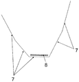
하지만, 이러한 파장들은 연중 내내 아침부터 밤까지 수집되어야 한다. 일반적으로, 태양빛의 입사각의 연간 변화는 넓은 범위의 지구 위도(terrestrial latitude)에서 약 60°로 유지된다. 도 1에 나타내어진 바와 같이, 위도로 경사진 표면(1)은, 겨울에는 작은 각도로부터 방사선(2)을 수용하고, 여름에는 더 큰 각도로부터 방사선(3)을 수용한다. 봄과 가을의 방사선(4)은 수직에 매우 가까운 각도로 수용될 것이다. (2)와 (3) 사이의 각도 변동은 언급된 바와 같이 약 60°이다. 반사 홀로그램들은 ±15°의 최대 변동을 포집할 수 있으므로, 이 경우 적어도 2 개의 다중화된 회절 격자들이 또한 필요하다. 파장 요건들과 함께 적어도 4 개의 다중화된 격자들이 요구된다. 다중화된 격자들의 수가 증가함에 따라 홀로그래픽 재료들이 효율성을 손실시킨다는 것을 감안하여, 이 4 개의 격자들의 최소치는 또한 재료의 물리학에 의해 부과된 최대치이다. 다시 말해, 홀로그램은 이전에 언급된 것보다 더 적게 포집해서는 안되지만, 효율성 손실이 방지되어야 하는 경우 더 많이 포집할 수 없다.However, these wavelengths must be collected from morning to night throughout the year. In general, the annual change in the angle of incidence of sunlight is maintained at about 60 ° in a wide range of terrestrial latitudes. As shown in Fig. 1, the latitudinal sloped
다른 한편으로, 도 1의 평면 구성과 같은 평면 구성에서는, [열 태양광 패널에서 파이프(6)로서 도 1에 도시된] 방사선 수용부들의 양이 크게 감소되는 경우, 방사선 출발 각도(radiation angle of departure: 5)가 매우 급격(steep)해야 하는 추가적인 문제가 존재한다. 이는 홀로그램 구성의 문제점을 제시한다: 이러한 급격한 각도는, 특히 프레넬 반사(Fresnel reflection)로 인해, 홀로그램의 과도한 광학 손실 없이 상업적으로 실행가능한 방식으로 얻어질 수 없다. 이러한 반사는 여하한의 광학 표면에 일어나며, 법선(normal)에 대한 입사각이 클수록, 이러한 반사가 더 많이 일어난다.On the other hand, in the planar configuration as in the planar configuration of Fig. 1, when the amount of the radiation receiving portions (shown in Fig. 1 as the
현 기술 수준에서 언급되는 해결책들 중 대부분에 제시된 바와 같은, 평면 태양광 패널 구성, 특히 홀로그램에 의한 평면 포집은 충분하지 않으며, 항상 제한된 성능을 야기할 것임이 명백하다.It is evident that flat planar solar panel construction, particularly planar capture by holograms, as most of the solutions mentioned at the state of the art are not sufficient, will always result in limited performance.
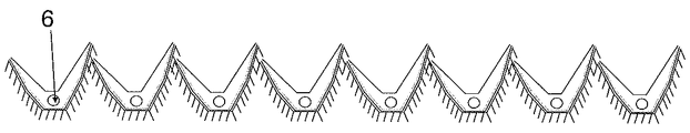
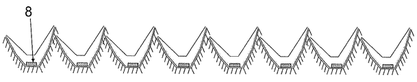
이러한 이유로, 본 발명은 여러 번 반복되는 3-차원 구조체를 해결책으로서 제안하며, 이의 3D 일체형 구조체(unitary structure)는 열 태양광 패널의 경우에 대해 도 2의 정면도에서 관찰될 수 있다. 상기 도면에서, 방사선 수용부(6)는 파이프, 예를 들어 구리 파이프이며, 이는 서로에 대해 각각 상이한 경사를 갖는 수 개의 평면들 또는 곡선들(7)에 의해 형성된 의사포물선 구조체의 중심에 위치된다. 도 2에 상응하는 도 3은 광기전 태양광 모듈을 도시하며, 이 경우 방사선 수용부(8)는 3D 일체형 구조체의 최하부에 하우징된(housed) 광기전 태양 전지이다.For this reason, the present invention proposes a three-dimensional structure repeated several times as a solution, and its 3D unitary structure can be observed in the front view of FIG. 2 for the case of a thermal solar panel. In the figure, the
따라서, 방사선 수용부들(6 또는 8)이 실질적으로 감소될 수 있는 시스템이 얻어진다. 다시 말해, 열 태양광 패널에서의 파이프들 간의 거리와, 광기전 태양광 모듈에서의 태양 전지들의 분지부(branch)들 간의 거리가 더 커질 수 있다. 패널이 위도로 경사져 있는 경우 태양광 방사선(2 및 3)의 입사각이 겨울과 여름에 따라 상이하기 때문에, 3D 일체형 구조체가 비대칭임을 유의하여야 한다.Thus, a system is obtained in which the
도 4에 나타내어진 바와 같이, 이 구성의 유일한 단점은, 상이한 평면들 또는 곡선들(7)이 위도로 경사진 평면 상에 투영(project)되는 경우, 겨울의 방사선(2)과 여름의 방사선(3) 간의 입사각의 변동이 언급된 60°에서 150°이상으로 상당히 증가한다는 점이다. 2 개의 다중화된 회절 격자들로 전체 각도 변동을 포집하는 것이 더 이상 가능하지 않다(하지만, 스펙트럼 대역폭의 70 %는 앞서 설명된 2 개의 파장 회절 격자들에 의해 여전히 포집될 수 있다).The only disadvantage of this configuration, as shown in Figure 4, is that when different planes or
전체 각도 변동을 포집할 수 없기 때문에, 본 발명은 집중 광학 요소로서 반사 홀로그램들(9)(도 5 참조, 항상 정면도)뿐만 아니라, 2 개의 요소들을 더 포함한다. 이들 중 하나는, 건축(construction)에 사용되는 절연 포일과 같이 심지어 절연 부분을 가질 수 있는 고-반사 표면(10)이다. 다른 요소는, 예를 들어 실리콘 또는 투명한 폴리우레탄과 같이, 높은 광학 품질을 갖는 투명한 광학 매질(11)이다. 방사선이 한 매질로부터 또 다른 매질로 진행할 때 매질의 변화로 인한 차이가 존재하지 않도록, 이 매질은 홀로그래픽 재료의 굴절률에 가까운 굴절률(n)을 가져야 한다.Since it is not possible to capture the total angular variation, the present invention further includes two elements as well as the reflective holograms 9 (see FIG. 5, always front view) as a focused optical element. One of these is a high-
본 패널의 3D 일체형 구조체는 다음과 같이 정의된다(도 5 참조):The 3D integral structure of this panel is defined as follows (see Figure 5):
- 중합체 또는 플라스틱 기저부(polymeric or plastic base: 12) - 상기 기저부 내에 패널의 3D 일체형 구조체의 의사포물선 형상을 제공하는 평면들 또는 곡선들(7)을 포함함 -,A polymeric or
- 패널의 3D 일체형 구조체 내부에서 이 중합체 또는 플라스틱 기저부에 배치되는 고-반사 표면(10),- a high-reflective surface (10) disposed in the polymer or plastic base within the 3D integral structure of the panel,
- 수 개의 다중화된 회절 격자들을 갖는 반사 홀로그램(9) - 이는 고-반사 표면(10)에 배치됨 -,- a reflective hologram (9) with several multiplexed diffraction gratings (9) arranged on the high-reflective surface (10)
- 파이프들(6) 또는 태양 전지들(8) 중 어느 하나인 방사선 수용부들, 및- radiation receptacles, either pipes (6) or solar cells (8), and
- 3D 일체형 구조체의 내부를 밀봉하는 투명한 광학 매질(11).A transparent optical medium (11) sealing the interior of the 3D integral structure.
그러므로, 3 개의 광학 요소들이 조합되며, 전체 150°의 입사각의 변동을 포집하기 위해 다음과 같은 방식으로 작동한다:Therefore, the three optical elements are combined and operate in the following manner to capture the variation of the incident angle of the entire 150 [deg.]:
a.) 반사 홀로그램(9)은 약 중심 60°이하를 포집한다. 회절에 의해 반사된 빔은 매질(11)의 임계 각도보다 더 큰 각도로 홀로그램을 나간다(이하 참조).a.) The reflection hologram (9) captures less than about 60 degrees of the center. The beam reflected by the diffracted beam exits the hologram at an angle greater than the critical angle of the medium 11 (see below).
b.) 고-반사 표면(10)은 중심 60°의 각 측 상에서 약 20°범위인 더 큰 각도를 포집한다. 다시 말해, 두 요소들, 즉 홀로그램(9) 및 반사 표면(10)으로, 100°의 입사각의 적어도 하나의 변동이 포집될 수 있다. 동일한 출발 각도로 매질(11)을 향해 반사시킴으로써, 매질(11) 내에 임계 각도보다 더 큰 각도가 존재하는 것이 보장된다.b.) The high-
c.) 매질(11)은 이중 목적을 갖는다: 하나는, 매질이 중심 100°보다 큰 각도들로 부딪히는 방사선을 포집하고, 프레넬 반사에 의해 이들을 반사시켜, 방사선이 홀로그램(9) 또는 반사 표면(10) 중 어느 하나에 의해 포집되었던 플라스틱 기저부(12)의 또 다른 평면 또는 곡선(7)을 향해 이들을 지향시킨다. 다른 하나는, 매질(11)이 평면들 또는 곡선들(7)보다 더 크고 평행하지 않은 각도로 구성된다(다음 문단 참조).c) The medium 11 has a dual purpose: one is to capture the radiation that the medium impinges at angles greater than 100 [deg.] in the center and reflect them by Fresnel reflection so that the radiation is reflected by the
그러므로, 매질(11)에서는 홀로그램(9)으로부터 회절되거나 반사 표면(10)으로부터 반사된 결과로서 복귀된 모든 방사선이 매질을 나가지 않는 것이 보장되는데, 이는 방사선이 임계 각도보다 더 큰 각도로 내측면에 부딪히기 때문이다. 그러므로, 방사선은 총 내부 반사(total internal reflection: TIR)를 통해 매질(11) 내로 복귀되며, 이때 홀로그램(9) 또는 반사 표면(10) 중 어느 하나가 방사선 수용부[(열 태양광 패널용 파이프들: 6) 및 (광기전 태양광 모듈용 광기전 태양 전지들: 8)]에 도달할 때까지 연속적으로 다시 작동할 것이다. TIR은 100 % 효율성을 가지므로, 손실이 존재하지 않는다. 홀로그램(9) 또는 고-반사 표면(10)과 관련하여, 효율이 95 % 또한 심지어는 98 %를 초과함에 따라, 각각의 회절 또는 반사의 손실을 최소화한다. 또한, 3D 일체형 구조체는 방사선 수용부(6 또는 8)에 도달할 때까지 회절 및/또는 반사의 최대 수가 3을 넘지 않도록 설계되므로, 손실이 훨씬 더 적다.Therefore, in the medium 11, it is ensured that all the radiation returned as a result of diffraction from the
이러한 효과들을 더 잘 설명하기 위해, 도 6 내지 도 8은 상이한 입사각을 갖는 연중 다른 시기를 도시한다. 비-한정적인(non-exclusive) 구성으로는, 도면번호 7a 내지 7e라고도 칭해지는 5 개의 면들(7)이 존재하며, 각각은 상이한 경사를 갖는다.To better illustrate these effects, Figures 6-8 show different times during the year with different angles of incidence. In a non-exclusive configuration, there are five
도 6에서, 겨울의 이른 아침 방사선(2)이 매우 급격한 각도로 평면들 또는 곡선들(7a 및 7b)을 때린다. 주로 이 평면들에서 프레넬 반사가 일어날 것이며, 방사선을 평면들 또는 곡선들(7d 또는 7e)로 보낸다. 매질(11)에 들어갈 때, 방사선은 대응하는 각도로 굴절된다. 그 도착 각도(angle of arrival)에 따라, 방사선은 홀로그램(9) 또는 반사 표면(10) 중 어느 하나에 의해 포집될 것이다. 각각 회절되거나 반사될 때, 방사선은 임계 각도보다 더 큰 각도로 매질(11)을 통해 진행하므로, 매질-공기 계면(medium-air interface)에 도달할 때 총 내부 반사(TIR)가 일어날 것이고, 방사선을 다시 매질 내로 보내며, 방사선 수용부(6 또는 8)에 도달할 때까지 수 개의 회절 및/또는 반사(최대 3)가 연속적으로 일어난다[상기 도면은 열 태양광 패널의 예시를 나타내며, 이의 방사선 수용부는 파이프(6)이다].In Fig. 6, the
도 7에서, 여름의 한낮 방사선(3)이 매우 급격한 각도로 평면들 또는 곡선들(7d 및 7e)을 때린다. 주로 이 평면들에서 프레넬 반사가 일어날 것이며, 방사선을 평면들 또는 곡선들(7a 또는 7b)로 보낸다. 매질(11)에 들어갈 때, 방사선은 대응하는 각도로 굴절된다. 도착 각도에 따라, 방사선은 홀로그램(9) 또는 반사 표면(10) 중 어느 하나에 의해 포집될 것이다. 각각 회절되거나 반사될 때, 방사선은 임계 각도보다 더 큰 각도로 매질(11)을 통해 진행하므로, 매질-공기 계면에 도달할 때 총 내부 반사(TIR)가 일어날 것이고, 방사선을 다시 매질 내로 보내며, 방사선 수용부(6 또는 8)에 도달할 때까지 수 개의 회절 및/또는 반사(최대 3)가 연속적으로 일어난다[상기 도면은 열 태양광 패널의 예시를 나타내며, 이의 방사선 수용부는 파이프(6)이다].In Fig. 7, summer
도 8에서, 봄 또는 가을의 방사선(4)이 매질(11)에 들어가고, 대응하는 각도로 굴절된다. 도착 각도에 따라, 방사선은 홀로그램(9) 또는 반사 표면(10) 중 어느 하나에 의해 포집될 것이다. 각각 회절되거나 반사될 때, 방사선은 임계 각도보다 더 큰 각도로 매질(11)을 통해 진행하므로, 매질-공기 계면에 도달할 때 총 내부 반사(TIR)가 일어날 것이고, 방사선을 다시 매질 내로 보내며, 방사선 수용부(6 또는 8)에 도달할 때까지 수 개의 회절 및/또는 반사(최대 3)가 연속적으로 일어난다[상기 도면은 열 태양광 패널의 예시를 나타내며, 이의 방사선 수용부는 파이프(6)이다].In Fig. 8, spring or
이러한 방식으로, 언급된 3D 일체형 구조체는 이에 따라 연중 매 계절 동안 방사선을 포집하며, 이를 방사선 수용부(6 또는 8)로 매우 효율적으로 지향시킨다. 오늘날 시장에서 이용가능한 것들에 상응하는 전력을 갖는 열 태양광 패널 또는 광기전 태양광 모듈(각각 도 9 및 도 10 참조)은 수 개의, 예를 들어 8 개 내지 10 개의 이 3D 일체형 구조체들을 함께 연결함으로써 얻어진다. 3D 일체형 구조체의 비대칭은 좌측 및 우측이 동일한 높이에 있지 않음을 의미한다. 하지만, 차광 손실(shading loss)이 겨울의 이른 아침에 감소되며, 연간 총 3 %에 도달하지 않는다.In this way, the mentioned 3D monolithic structure accordingly captures the radiation during every year during the year and directs it to the
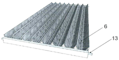
환경에 강한(environmentally resistant) 저항적 중합체 재료로 만들어진 기저부(12) 및 환경에 강한 광학 중합체 재료(예를 들어, 실리콘 또는 폴리우레탄)로 만들어진 매질(11) 둘 모두는 플라스틱 주형(plastic molding)에 의해 압출가공(extrude)될 수 있다. 이들은 강성(rigidity)을 보장함에 따라, 프레임이 불필요하며, 뿐만 아니라 상당한 무게 감소를 가져온다. 다른 한편으로, 기저부(12)가 주형으로부터의 압출성형에 의해 만들어지기 때문에, 이는 동일한 압출성형으로 여하한의 광기전 태양광 시스템의 장착 구조체들에 패널들을 고정하는데 필요한 모든 앵커링 요소(anchoring element)들을 포함할 수 있다. 또한, 이는, 예를 들어 열 태양광 패널의 경우, 더 큰 직경을 갖는 수집기 파이프들(13)을 패널의 단부들에 하우징하는 데 필요한 개구부들 또는 공동(cavity)들을 포함할 수 있다(도 11 참조). 또한, 광기전 태양광 모듈에서, 이는 전지들 간에 모든 종류의 전기적 연결을 만드는데 필요한 개구부들을 포함할 수 있다.Both the base 12 made of an environmentally resistant resistive polymeric material and the medium 11 made of an environmentally resistant optical polymeric material (e.g., silicone or polyurethane) (Extruded). As they ensure rigidity, frames are unnecessary, as well as significant weight reduction. On the other hand, since the
열 태양광 패널과 광기전 태양광 모듈 간에 본 설계에 영향을 주는 근본적인 차이가 존재한다는 것이 언급되어야 한다: 열 태양광 패널에서는, 구조체 내부에 열을 보유하여 손실을 최소화하고 열-이송 유체의 가열을 보장하는 것이 관심대상이다(파이프들이 고체 매질 내에 완전히 매입(imbue)됨에 따라, 대류로 인한 손실은 미미하기 때문에, 전도로 인한 손실을 지칭한다). 하지만, 광기전 태양광 모듈에서는, 태양 전지들의 효율성이 이의 온도에 따라 감소하기 때문에, 가능한 한 많은 열이 소실되어야 한다.It should be noted that there is a fundamental difference between the thermal solar panel and the photovoltaic solar module that affects the design: thermal solar panels have heat inside the structure to minimize losses and heat (As the pipes are imbued completely within the solid medium, the losses due to convection are insignificant, so the loss due to conduction is referred to). However, in photovoltaic photovoltaic modules, the efficiency of the solar cells decreases with their temperature, so as much heat as possible must be lost.
본 설계에서, 이러한 차이는 플라스틱 기저부(12)와 매질(11) 둘 모두에 대해 상이한 플라스틱 재료들을 선택함으로써 해결되며, 이는 어떠한 경우에서도 환경에 강하다. 구체적으로, 열 태양광 패널에 대해, 매우 낮은 열 전도도(k), 예를 들어 약 0.02 내지 0.03 Wㆍm-1ㆍK- 1를 갖는 플라스틱 재료들이 관심대상이다. 광기전 태양광 모듈에 대해, 그 반대가 적용가능하다. 그러므로, 광기전 태양광 모듈들에 대해, 플라스틱 기저부(12)와 매질(11) 둘 모두를 형성하는 플라스틱 재료들은, 예를 들어 0.05 Wㆍm-1ㆍK-1보다 큰, 그리고 심지어는 0.07 Wㆍm-1ㆍK-1보다 큰 열 전도도를 가져야 한다.In this design, this difference is solved by selecting different plastic materials for both the
도 1은 위도로 경사진 표면(1) 상에서 겨울(2)과 여름(3) 사이의 태양광 방사선의 입사각 변동을 나타낸다. 겨울의 이른 아침의 태양광 방사선(2)은 더 작은 각도로 표면(1)에 부딪히는 반면, 여름의 한낮의 태양광 방사선(3)은 더 큰 각도로 그 동일한 표면(1)에 부딪힌다. 두 각도들 간의 차이는 다수의 위도에 대해 약 60°이다. 봄 또는 가을의 방사선(4)은 거의(virtually) 수직인 방식으로 상기 표면(1)에 부딪힌다. 상기 방사선이 서로 충분히 이격된 방사선 수용부들(6)에 부딪혀, 열 태양광 패널 또는 광기전 태양광 모듈을 경제적으로 실행가능하게 하려면, 방사선의 출발 각도(5)가 매우 급격해야 하는데, 이는 현재의 홀로그래픽 기술에서 매우 고가이며 복잡하다.Figure 1 shows the incident angle variation of solar radiation between winter (2) and summer (3) on a latitudinal sloping surface (1). The
도 2는 제안된 열 태양광 패널의 3D 일체형 구조체의 정면도를 나타낸다. 서로에 대해 각각 상이한 경사를 갖는 수 개의 평면들 또는 곡선들(7)은 의사포물선 구조체를 형성하며, 이의 중심은 방사선 수용부, 이 경우 파이프(6)에 의해 점유된다.2 shows a front view of the 3D integrated structure of the proposed thermal solar panel. Several planes or
도 3은 제안된 광기전 태양광 모듈의 3D 일체형 구조체의 정면도를 나타낸다. 서로에 대해 각각 상이한 경사를 갖는 수 개의 평면들 또는 곡선들(7)은 의사포물선 구조체를 형성하며, 이의 최하부는 방사선 수용부, 이 경우 광기전 태양 전지(8)에 의해 점유된다.3 is a front view of the 3D integrated structure of the proposed photovoltaic solar module. Several planes or
도 4는, 상이한 평면들 또는 곡선들(7)이 위도로 경사진 평면에 투영되는 경우, 겨울(2)과 여름(3) 간의 방사선 입사각의 변동의 설명을 나타낸다. 이러한 각도 변동은 150°를 초과한다.Fig. 4 shows a description of the variation of the radiation incidence angle between winter (2) and summer (3) when different planes or curves (7) are projected on a plane inclined to latitude. This angular variation exceeds 150 degrees.
도 5는, 상이한 요소들: 플라스틱 기저부(12) - 이의 내측면은 서로에 대해 각각 상이한 경사를 갖는 평면들 또는 곡선들(7)로 구성됨 -; 상기 평면들 또는 곡선들(7)을 덮는 고-반사 표면(10); 반사 표면(10)을 덮는 수 개의 다중화된 회절 격자들을 갖는 반사 홀로그램(9), 및 전체 조립체를 밀봉하는 투명한 광학 매질(11)을 갖는 태양광 패널(이 경우, 열 태양광 패널)의 3D 일체형 구조체의 정면도를 나타낸다. 방사선 수용부, 이 경우 파이프(6)가 그 안에 배치된다.Figure 5 shows the different elements: plastic base 12 - the inner side of which is composed of planes or
도 6은 겨울의 이른 아침 입사 방사선(2)이 태양광 패널(이 경우, 열 태양광 패널)의 3D 일체형 구조체에 도달할 때의 이의 광학 경로를 나타낸다. 상기 방사선(2)은 매질(11)의 표면에 직접적으로 프레넬 반사에 의해 평면들(7a 및 7b)에서 평면들(7d 또는 7e)을 향해 반사된다. 그 안의 매질(11)에 도달할 때, 이는 대응하는 각도로 굴절되어, 반사 홀로그램(9) 또는 고-반사 표면(10)을 때린다. 이는 임계 각도보다 더 큰 각도로 다시 매질(11)을 향해 방사선을 각각 회절 또는 반사시켜, TIR이 매질 내에 일어난다. 연속적인 회절 및/또는 반사는 방사선을 방사선 수용부[이 경우, 파이프(6)]를 향해 안내한다.6 shows its optical path when the early
도 7은 여름의 한낮 입사 방사선(3)이 태양광 패널(이 경우, 열 태양광 패널)의 3D 일체형 구조체에 도달할 때의 이의 광학 경로를 나타낸다. 상기 방사선(3)은 매질(11)의 표면에 직접적으로 프레넬 반사에 의해 평면들 또는 곡선들(7d 및 7e)에서 평면들 또는 곡선들(7a 또는 7b)을 향해 반사된다. 그 안의 매질(11)에 도달할 때, 이는 대응하는 각도로 굴절되어, 반사 홀로그램(9) 또는 고-반사 표면(10)을 때린다. 이는 임계 각도보다 더 큰 각도로 다시 매질(11)을 향해 방사선을 각각 회절 또는 반사시켜, TIR이 매질 내에 일어난다. 연속적인 회절 및/또는 반사는 방사선을 방사선 수용부[이 경우, 파이프(6)]를 향해 안내한다.Fig. 7 shows the optical path of the
도 8은 봄 또는 가을의 입사 방사선(4)이 태양광 패널(이 경우, 열 태양광 패널)의 3D 일체형 구조체에 도달할 때의 이의 광학 경로를 나타낸다. 모든 평면들 또는 곡선들(7a 내지 7e)에서, 매질(11)에 도달할 때, 이는 대응하는 각도로 굴절되어, 반사 홀로그램(9) 또는 고-반사 표면(10)을 때린다. 이는 임계 각도보다 더 큰 각도로 다시 매질(11)을 향해 방사선을 각각 회절 또는 반사시켜, TIR이 매질 내에 일어난다. 연속적인 회절 및/또는 반사는 방사선을 방사선 수용부[이 경우, 파이프(6)]를 향해 안내한다.Fig. 8 shows its optical path when the
도 9는 수 개의(이 경우, 8 개) 3D 일체형 구조체들로 구성된 완전한 열 태양광 패널의 정면도를 나타낸다. 열 태양광 패널의 방사선 수용부는 파이프들(6)로 구성된다.Figure 9 shows a front view of a complete thermal solar panel comprised of several (in this case, eight) 3D monolithic structures. The radiation receiving portion of the thermal solar panel is composed of pipes (6).
도 10은 수 개의(이 경우, 8 개) 3D 일체형 구조체들로 구성된 완전한 광기전 태양광 모듈의 정면도를 나타낸다. 광기전 태양광 모듈의 방사선 수용부는 광기전 태양 전지들(8)로 구성된다.Figure 10 shows a front view of a complete photovoltaic module consisting of several (in this case, eight) 3D monolithic structures. The radiation receiving portion of the photovoltaic solar module is composed of photovoltaic
도 11은 열 태양광 패널의 가능한 비-한정적인 실시예를 나타낸다. 8 개의 3D 일체형 구조체들은, 예를 들어 8 mm의 외경을 갖는 8 개의 파이프들(6)을 포함하며, 이는 더 큰 직경, 예를 들어 18 mm를 갖는 2 개의 수집기 파이프들(13)에 용접된다.Figure 11 shows a possible non-limiting embodiment of a thermal solar panel. The eight 3D integral structures include eight
도 12는 광기전 태양광 모듈의 가능한 비-한정적인 실시예를 나타낸다. 8 개의 3D 일체형 구조체들은, 예를 들어 각각 31 x 125 mm의 광전지(photovoltaic cell: 8)들의 8 개의 분지부들을 포함한다. 이들 간의 연결은, 전지들 간의 여하한의 종류의 연결을 허용하는 플라스틱 기저부(12)의 개구부들로 인해 매우 다용도를 갖는다.Figure 12 shows a possible non-limiting embodiment of a photovoltaic solar module. The eight 3D integral structures include, for example, eight branches of
본 발명의 The 실시예들Examples
바람직하지만 비-한정적인 구성에서, 열 태양광 패널과 광기전 태양광 패널 둘 모두는 도 2 내지 도 10에 설명된 바와 같은 8 개의 3D 일체형 구조체들로 구성될 것이다. 상기 구조체들의 치수는, 높이가 약 80 mm이고, 폭이 약 120 mm이며, 길이가 약 1.5 미터일 것이다. 그러므로, 태양광 패널은 약 1,500 x 1,000 x 80 mm의 치수를 가질 것이며, 즉 이는 여하한의 표준 패널의 크기에 가장 가깝다. 플라스틱 기저부(12)와 덮고 밀봉하는 매질(11) 둘 모두는 환경에 강한 플라스틱 재료들로 만들어지며, 또한 기저부는 여하한의 형상에 적응할 수 있음에 따라, 사용되는 재료를 감소시키며, 총 무게가 표준 상업 패널의 무게의 절반 이상으로 감소될 수 있다.In a preferred but non-limiting configuration, both the thermal solar panel and the photovoltaic solar panel will consist of eight 3D monolithic structures as illustrated in FIGS. 2-10. The dimensions of the structures would be about 80 mm in height, about 120 mm in width, and about 1.5 meters in length. Therefore, the solar panel will have dimensions of about 1,500 x 1,000 x 80 mm, which is closest to the size of any standard panel. Both the
플라스틱 기저부(12)가 주형으로 만들어질 수 있기 때문에, 직렬 및 병렬로, 광기전 태양 전지의 다용도 연결을 위한 개구부들 또는 장착 시스템을 위한 앵커들을 포함하는 모든 필수 요소들을 포함할 수 있다. 마찬가지로, 열 태양광 패널의 경우에 대해, 상기 플라스틱 기저부(12)는 수집기 파이프들(13)에서 취하는 요소들에 저항적이도록 필요한 연장부들로 만들어질 수 있다(도 11 참조).Because the
열 태양광 패널의 경우, 방사선 수용부들은 파이프들(6)이다. 설명된 실시예에서, 이들은 8 mm의 외경을 갖는 구리 파이프들일 수 있다. 수집기 파이프들(13)은, 예를 들어 18 mm의 더 큰 직경을 가질 수 있다. 총 8 개의 파이프들(6)이 존재하기 때문에, 달성되는 유체 열 용량은 종래의 평면 수집기의 유체 열 용량과 유사하다. 하지만, 매질(11)을 이용한 밀봉이 대류로 인한 손실을 최소화하기 때문에, 이의 효율이 고온에서 가열 유체들에 대해 개선될 수 있다. 또한, 낮은 열 전도도를 갖는 재료를 이용한 구성은 전도로 인한 손실을 상당히 감소시킬 수 있다.In the case of a thermal photovoltaic panel, the radiation receptacles are
이 실시예에서, 광기전 태양광 모듈은 각각 15 개의 셀들의 8 개의 분지부들로 부착된 31 x 125 mm의 120 개의 셀들의 어레이로 구성될 수 있다. 그러므로, 완전한 모듈은 약 1,800 x 1,000 x 80 mm의 치수를 가질 것이다. 17 %의 효율을 갖는 종래의 전지들이 사용되는 경우, 이 구성은 약 250 W의 정격 출력(rated power)을 갖는 모듈을 얻는다. 동일한 전력의 종래의 광기전 모듈과 동일한 전기 파라미터들을 얻기 위해, 병렬로 4 개의 분지부들과 연결이 만들어져야 하며, 다음 4 개의 분지부들과 직렬로 연결된다.In this embodiment, the photovoltaic solar module may be comprised of an array of 120 cells of 31 x 125 mm attached with eight branches of 15 cells each. Therefore, the complete module will have dimensions of about 1,800 x 1,000 x 80 mm. When conventional batteries having an efficiency of 17% are used, this configuration results in a module having a rated power of about 250 W. To obtain the same electrical parameters as a conventional photovoltaic module of the same power, a connection with four branch portions in parallel should be made and connected in series with the next four branch portions.
Claims (7)
한 개 또는 수 개의 3D 일체형 구조체들 또는 공동(cavity)들을 형성하는 중합체 기저부(polymeric base; 12), 이러한 공동들의 내부를 덮는 고-반사 표면(10), 상기 고-반사 표면(10)을 덮는 홀로그램(9), 방사선 수용부 - 상기 방사선 수용부는 열 태양광 패널의 경우 파이프들(6)이거나, 광기전 태양광 모듈의 경우 광기전 태양 전지들(8)임 -, 및 전체 3D 일체형 구조체를 덮고 밀봉하며, 홀로그래픽 재료(holographic material: 9)의 굴절률과 유사한 굴절률(n)을 갖는 투명한 광학 매질(11)로 구성되는 것을 특징으로 하는 열 또는 광기전 태양광 패널.In a thermal or photovoltaic solar panel,
A polymeric base 12 forming one or several 3D monolithic structures or cavities, a high-reflective surface 10 covering the interior of such cavities, a high-reflective surface 10 covering the high- The hologram 9 and the radiation receiving part are the pipes 6 in the case of the thermal solar panel or the photovoltaic solar cells 8 in the case of the photovoltaic solar module and the entire 3D integrated structure And is composed of a transparent optical medium (11) having a refractive index ( n ) similar to the refractive index of a holographic material (9).
주형들로부터 압출성형(extrude)될 수 있는 상기 중합체 기저부(12)는, 기저부 형상으로, 장착 시스템에 앵커링하기 위한 모든 가능한 앵커, 그리고 열 태양광 패널들의 수집기 튜브들(13)을 하우징하는 형성부들 또는 광기전 태양광 모듈들에서 상기 태양 전지들(8) 사이에 여하한의 타입의 전기적 연결을 만드는 데 필요한 개구부들과 같이, 추가 연장부들을 포함하는 것을 특징으로 하는 열 또는 광기전 태양광 패널.The method according to claim 1,
The polymer base 12, which can be extruded from the molds, has a base shape, all possible anchors for anchoring to the mounting system, and formers (not shown) for housing collector tubes 13 of thermal solar panels Or openings necessary to make any type of electrical connection between the solar cells (8) in the photovoltaic photovoltaic modules, characterized in that it comprises additional extensions .
상기 중합체 기저부(12)의 3D 구조 유닛들은 변동가능한 수의 상이한 평면들 또는 곡선들(7)에 의해 구성되고, 각각은 서로에 대해 상이한 경사를 갖는 것을 특징으로 하는 열 또는 광기전 태양광 패널.The method according to claim 1,
Wherein the 3D structural units of the polymer base (12) are constituted by a variable number of different planes or curves (7), each having a different slope with respect to each other.
입사 태양광 방사선이 포집(capture)되고, 상이한 광학 요소에 의해 입사각에 따라 상기 방사선 수용부(6 또는 8)를 향해 지향되며: 약 60°이하가 상기 홀로그램(9)에 의해 포집되고, 이에 따라 이는 적절한 회절 격자들로 설계되어야 하며; 또 다른 약 40°가 상기 고-반사 표면(10)에 의해 포집되고; 나머지는 공기와 상기 매질(11)의 계면 상에서의 프레넬 반사(Fresnel reflection)에 의해 3D 일체형 구조체 내에 반사되는 것을 특징으로 하는 열 또는 광기전 태양광 패널.The method according to claim 1,
Incident solar radiation is captured and directed by the different optical elements towards the radiation receiving portion 6 or 8 according to the incident angle: about 60 degrees or less is collected by the hologram 9, It should be designed with proper diffraction gratings; Another about 40 [deg.] Is captured by the high-reflective surface 10; And the remainder is reflected in the 3D integrated structure by air and Fresnel reflection on the interface of the medium (11).
상기 홀로그램(9)은 공기와 상기 매질(11)의 임계 각도보다 더 큰 출발 각도(angles of departures)로 회절하도록 설계되는 것을 특징으로 하는 열 또는 광기전 태양광 패널.The method according to claim 1,
Characterized in that the hologram (9) is designed to diffract at angles of departments greater than the critical angle of air and the medium (11).
상기 투명한 광학 매질(11) - 상기 광학 매질은 또한 주형들로부터 압출성형될 수 있음 - 은 상기 평면들 또는 곡선들(7)의 경사 각도보다 더 크고 상이한 경사 각도를 가져, 상기 홀로그램(9)에 의해 회절되는 방사선과 상기 고-반사 표면(10)에 의해 반사되는 방사선 둘 모두가 공기와 상기 매질의 임계 각도보다 더 큰 각도로 상기 매질(11)로 재지향(redirect)되어, 상기 방사선이 총 내부 반사(total internal reflection: TIR)에 의해 상기 매질(11)에 포집되는 것을 특징으로 하는 열 또는 광기전 태양광 패널.The method according to claim 1,
The transparent optical medium (11), which can also be extruded from the molds, has an inclination angle greater than the inclination angle of the planes or curves (7) Both the radiation diffracted by the high-reflectivity surface 10 and the radiation diffracted by the high-reflectivity surface 10 are redirected to the medium 11 at an angle greater than the critical angle of air and the medium, is collected in the medium (11) by total internal reflection (TIR).
상기 중합체 기저부(12)와 상기 투명한 광학 매질(11) 둘 모두는 열 태양광 패널들의 경우 낮은 열 전도도를 갖는 환경에 강한(environmentally resistant) 중합체 재료들로 만들어지고, 광기전 태양광 모듈들의 경우 높은 열 전도도를 갖는 환경에 강한 중합체 재료들로 만들어짐에 따라, 전도로 인한 열 보유 또는 소실을 각각 보장하는 것을 특징으로 하는 열 또는 광기전 태양광 패널.The method according to claim 1,
Both the polymer base 12 and the transparent optical medium 11 are made of environmentally resistant polymeric materials having low thermal conductivity in the case of thermal solar panels, Characterized in that the heat or photovoltaic panel is made of polymeric materials resistant to environmental conditions having thermal conductivity, thereby ensuring heat retention or loss due to conduction, respectively.
Applications Claiming Priority (3)
| Application Number | Priority Date | Filing Date | Title |
|---|---|---|---|
| ESP201331199 | 2013-08-01 | ||
| ES201331199A ES2527969B1 (en) | 2013-08-01 | 2013-08-01 | Three-dimensional thermal or photovoltaic solar panel with built-in holography |
| PCT/ES2014/070630 WO2015015041A1 (en) | 2013-08-01 | 2014-08-01 | Three-dimensional thermal or photovoltaic solar panel with integral holograph |
Publications (1)
| Publication Number | Publication Date |
|---|---|
| KR20160067085A true KR20160067085A (en) | 2016-06-13 |
Family
ID=51494311
Family Applications (1)
| Application Number | Title | Priority Date | Filing Date |
|---|---|---|---|
| KR1020167004720A KR20160067085A (en) | 2013-08-01 | 2014-08-01 | Three-dimensional thermal or photovoltaic solar panel with integral holograph |
Country Status (13)
| Country | Link |
|---|---|
| US (1) | US20160197221A1 (en) |
| EP (1) | EP3029744B1 (en) |
| JP (1) | JP2016534309A (en) |
| KR (1) | KR20160067085A (en) |
| AU (1) | AU2014298329A1 (en) |
| BR (1) | BR112016002271A2 (en) |
| CA (1) | CA2919949A1 (en) |
| CL (1) | CL2016000261A1 (en) |
| ES (1) | ES2527969B1 (en) |
| MA (1) | MA38861B1 (en) |
| MX (1) | MX2016001340A (en) |
| PE (1) | PE20160559A1 (en) |
| WO (1) | WO2015015041A1 (en) |
Families Citing this family (7)
| Publication number | Priority date | Publication date | Assignee | Title |
|---|---|---|---|---|
| CN105406810B (en) * | 2015-11-23 | 2017-11-17 | 安徽宏宇铝业有限公司 | A kind of energy saving and environment friendly solar energy frame aluminium section bar |
| CA3086351C (en) * | 2017-12-22 | 2022-04-12 | Hyperstealth Biotechnology Corporation | System and method of amplifying solar panel output |
| CN108764300B (en) * | 2018-05-07 | 2021-09-28 | 国网天津市电力公司 | Big data clustering analysis method for optimal inclination angle of fixed photovoltaic power generation system |
| CN112005489B (en) * | 2018-05-08 | 2023-04-11 | 博立码杰通讯(深圳)有限公司 | Double-sided concentrating solar device and system |
| ES2746036A1 (en) * | 2018-09-04 | 2020-03-04 | Ursu Silvia Mihaela Toader | PHOTOVOLTAIC THERMAL ALTERNATIVE HYBRID SOLAR CAPTION SYSTEM (Machine-translation by Google Translate, not legally binding) |
| US20230383995A1 (en) * | 2020-10-06 | 2023-11-30 | The Regents Of The University Of California | Nonimaging asymmetric shadeless collector |
| CN115825763B (en) * | 2023-01-10 | 2023-10-27 | 伟杰科技(苏州)有限公司 | Intelligent battery monitoring system and monitoring method thereof |
Family Cites Families (21)
| Publication number | Priority date | Publication date | Assignee | Title |
|---|---|---|---|---|
| US4863224A (en) | 1981-10-06 | 1989-09-05 | Afian Viktor V | Solar concentrator and manufacturing method therefor |
| US4490981A (en) * | 1982-09-29 | 1985-01-01 | Milton Meckler | Fixed solar concentrator-collector-satelite receiver and co-generator |
| JPH05224018A (en) | 1991-07-30 | 1993-09-03 | Nippondenso Co Ltd | Light guide device |
| EP0659531B1 (en) * | 1993-12-24 | 2000-05-17 | Röhm Gmbh | Process for extrusion of plastic plates and Fresnel lenses produced therefrom |
| US5877874A (en) * | 1995-08-24 | 1999-03-02 | Terrasun L.L.C. | Device for concentrating optical radiation |
| JPH11307803A (en) * | 1998-04-21 | 1999-11-05 | Toyota Motor Corp | Converging apparatus |
| US6020554A (en) * | 1999-03-19 | 2000-02-01 | Photovoltaics International, Llc | Tracking solar energy conversion unit adapted for field assembly |
| US6274860B1 (en) | 1999-05-28 | 2001-08-14 | Terrasun, Llc | Device for concentrating optical radiation |
| JP2003052185A (en) * | 2001-05-30 | 2003-02-21 | Canon Inc | Power converter, and photovoltaic element module using the same and power generator |
| US20060191566A1 (en) * | 2005-02-28 | 2006-08-31 | Applied Optical Materials | Solar concentrator system using photonic engineered materials |
| TWI466304B (en) * | 2006-07-07 | 2014-12-21 | Energy Related Devices Inc | Micro concentrators elastically coupled with spherical photovoltaic cells |
| DE102006059417A1 (en) * | 2006-12-15 | 2008-06-26 | Solartec Ag | Photovoltaic device with holographic structure for deflecting incident solar radiation, as well as manufacturing method thereof |
| US20080185033A1 (en) * | 2007-02-06 | 2008-08-07 | Kalejs Juris P | Solar electric module |
| US20080257400A1 (en) * | 2007-04-17 | 2008-10-23 | Mignon George V | Holographically enhanced photovoltaic (hepv) solar module |
| DE102008026760A1 (en) * | 2008-06-05 | 2009-12-10 | Nanooptics Gmbh | Solar cell with light trap and solar module |
| IT1395352B1 (en) | 2009-07-09 | 2012-09-14 | Orlandi | INTEGRATED SYSTEM WITH VERY HIGH VALUE OF ENERGY CONVERSION INCLUDING HOLOGRAPHIC, THERMAL AND ANY OPTICAL ELEMENTS TO TRANSFORM SOLAR ENERGY IN ECO-FRIENDLY ENERGY. |
| US20110162712A1 (en) * | 2010-01-07 | 2011-07-07 | Martin David Tillin | Non-tracked low concentration solar apparatus |
| US8815402B2 (en) * | 2010-03-31 | 2014-08-26 | Ppg Industries Ohio, Inc. | Mirror having reflective coatings on a first surface and an opposite second surface |
| US8223433B2 (en) * | 2010-08-09 | 2012-07-17 | Palo Alto Research Center Incorporated | Stationary sunlight redirecting element and system |
| US20130167903A1 (en) * | 2011-11-14 | 2013-07-04 | Prism Solar Technologies Incorporated | Encapsulated solar energy concentrator |
| WO2013078209A1 (en) * | 2011-11-23 | 2013-05-30 | Prism Solar Technologies Incorporated | Encapsulated solar energy concentrator |
-
2013
- 2013-08-01 ES ES201331199A patent/ES2527969B1/en not_active Expired - Fee Related
-
2014
- 2014-08-01 MA MA38861A patent/MA38861B1/en unknown
- 2014-08-01 WO PCT/ES2014/070630 patent/WO2015015041A1/en active Application Filing
- 2014-08-01 KR KR1020167004720A patent/KR20160067085A/en not_active Application Discontinuation
- 2014-08-01 EP EP14761672.6A patent/EP3029744B1/en not_active Not-in-force
- 2014-08-01 BR BR112016002271A patent/BR112016002271A2/en not_active IP Right Cessation
- 2014-08-01 CA CA2919949A patent/CA2919949A1/en not_active Abandoned
- 2014-08-01 MX MX2016001340A patent/MX2016001340A/en unknown
- 2014-08-01 JP JP2016530558A patent/JP2016534309A/en active Pending
- 2014-08-01 AU AU2014298329A patent/AU2014298329A1/en not_active Abandoned
- 2014-08-01 PE PE2016000208A patent/PE20160559A1/en not_active Application Discontinuation
- 2014-08-01 US US14/909,423 patent/US20160197221A1/en not_active Abandoned
-
2016
- 2016-02-01 CL CL2016000261A patent/CL2016000261A1/en unknown
Also Published As
| Publication number | Publication date |
|---|---|
| BR112016002271A2 (en) | 2017-08-01 |
| EP3029744A1 (en) | 2016-06-08 |
| MA38861A1 (en) | 2016-11-30 |
| JP2016534309A (en) | 2016-11-04 |
| PE20160559A1 (en) | 2016-06-10 |
| CA2919949A1 (en) | 2015-02-05 |
| MX2016001340A (en) | 2016-07-07 |
| US20160197221A1 (en) | 2016-07-07 |
| EP3029744B1 (en) | 2017-07-05 |
| MA38861B1 (en) | 2017-12-29 |
| WO2015015041A1 (en) | 2015-02-05 |
| ES2527969A1 (en) | 2015-02-02 |
| CL2016000261A1 (en) | 2016-09-30 |
| AU2014298329A1 (en) | 2016-02-18 |
| ES2527969B1 (en) | 2015-11-23 |
Similar Documents
| Publication | Publication Date | Title |
|---|---|---|
| EP3029744B1 (en) | Solar module comprising holographic reflecting concentrating optics | |
| Sharaf et al. | Concentrated photovoltaic thermal (CPVT) solar collector systems: Part II–Implemented systems, performance assessment, and future directions | |
| Jaaz et al. | Design and development of compound parabolic concentrating for photovoltaic solar collector | |
| JP5837746B2 (en) | Light guiding solar panel and manufacturing method thereof | |
| US20120192922A1 (en) | Solar collector | |
| US20100154866A1 (en) | Hybrid solar power system | |
| US8101850B2 (en) | Asymmetric parabolic compound concentrator with photovoltaic cells | |
| US20160087135A1 (en) | Light-Concentrating Mechanism, Photovoltaic Power Generation Device, Window Structure, and Window Glass | |
| CA2590165A1 (en) | Solar energy collection system | |
| US8477413B2 (en) | Optical element | |
| Paul | Application of compound parabolic concentrators to solar photovoltaic conversion: A comprehensive review | |
| CA2738647A1 (en) | Solar collector panel | |
| JPH0629883B2 (en) | Solar power generator | |
| WO2010101644A1 (en) | 3-d non-imaging radiant energy concentrator | |
| CN102064225B (en) | Preposed fisheye meniscus lens group condenser | |
| EP2620987B1 (en) | Devices and systems for concentration / collection of solar energy and industrial and household applications | |
| JP2010169981A (en) | Solar lens and solar light utilizing device | |
| RU2659319C1 (en) | Fixed solar radiation concentrator with optical method of alignment | |
| TWI578024B (en) | Light collecting module | |
| RU201526U1 (en) | Holographic film based on prismacons | |
| NL2007970C2 (en) | Solar concentrator system. | |
| KR101130765B1 (en) | Side solar concentrator | |
| KR101217247B1 (en) | condensing type solar cell | |
| ES2563645B1 (en) | Modular solar concentration system without tracking by combining conventional optics and holographic optical elements (HOE’s) | |
| WO2013156695A1 (en) | Device for controlling energy conversion in hybrid thermal and photovoltaic solar concentrators |
Legal Events
| Date | Code | Title | Description |
|---|---|---|---|
| WITN | Application deemed withdrawn, e.g. because no request for examination was filed or no examination fee was paid |