KR20160064868A - Body massage system and Method using sound pressure - Google Patents
Body massage system and Method using sound pressure Download PDFInfo
- Publication number
- KR20160064868A KR20160064868A KR1020140169106A KR20140169106A KR20160064868A KR 20160064868 A KR20160064868 A KR 20160064868A KR 1020140169106 A KR1020140169106 A KR 1020140169106A KR 20140169106 A KR20140169106 A KR 20140169106A KR 20160064868 A KR20160064868 A KR 20160064868A
- Authority
- KR
- South Korea
- Prior art keywords
- vibration
- massage
- coupled
- unit
- generating
- Prior art date
Links
Images


Classifications
-
- A—HUMAN NECESSITIES
- A61—MEDICAL OR VETERINARY SCIENCE; HYGIENE
- A61H—PHYSICAL THERAPY APPARATUS, e.g. DEVICES FOR LOCATING OR STIMULATING REFLEX POINTS IN THE BODY; ARTIFICIAL RESPIRATION; MASSAGE; BATHING DEVICES FOR SPECIAL THERAPEUTIC OR HYGIENIC PURPOSES OR SPECIFIC PARTS OF THE BODY
- A61H23/00—Percussion or vibration massage, e.g. using supersonic vibration; Suction-vibration massage; Massage with moving diaphragms
- A61H23/02—Percussion or vibration massage, e.g. using supersonic vibration; Suction-vibration massage; Massage with moving diaphragms with electric or magnetic drive
- A61H23/0218—Percussion or vibration massage, e.g. using supersonic vibration; Suction-vibration massage; Massage with moving diaphragms with electric or magnetic drive with alternating magnetic fields producing a translating or oscillating movement
- A61H23/0236—Percussion or vibration massage, e.g. using supersonic vibration; Suction-vibration massage; Massage with moving diaphragms with electric or magnetic drive with alternating magnetic fields producing a translating or oscillating movement using sonic waves, e.g. using loudspeakers
-
- A—HUMAN NECESSITIES
- A61—MEDICAL OR VETERINARY SCIENCE; HYGIENE
- A61H—PHYSICAL THERAPY APPARATUS, e.g. DEVICES FOR LOCATING OR STIMULATING REFLEX POINTS IN THE BODY; ARTIFICIAL RESPIRATION; MASSAGE; BATHING DEVICES FOR SPECIAL THERAPEUTIC OR HYGIENIC PURPOSES OR SPECIFIC PARTS OF THE BODY
- A61H23/00—Percussion or vibration massage, e.g. using supersonic vibration; Suction-vibration massage; Massage with moving diaphragms
- A61H23/02—Percussion or vibration massage, e.g. using supersonic vibration; Suction-vibration massage; Massage with moving diaphragms with electric or magnetic drive
- A61H23/0254—Percussion or vibration massage, e.g. using supersonic vibration; Suction-vibration massage; Massage with moving diaphragms with electric or magnetic drive with rotary motor
-
- A—HUMAN NECESSITIES
- A61—MEDICAL OR VETERINARY SCIENCE; HYGIENE
- A61H—PHYSICAL THERAPY APPARATUS, e.g. DEVICES FOR LOCATING OR STIMULATING REFLEX POINTS IN THE BODY; ARTIFICIAL RESPIRATION; MASSAGE; BATHING DEVICES FOR SPECIAL THERAPEUTIC OR HYGIENIC PURPOSES OR SPECIFIC PARTS OF THE BODY
- A61H39/00—Devices for locating or stimulating specific reflex points of the body for physical therapy, e.g. acupuncture
- A61H39/04—Devices for pressing such points, e.g. Shiatsu or Acupressure
-
- A—HUMAN NECESSITIES
- A61—MEDICAL OR VETERINARY SCIENCE; HYGIENE
- A61H—PHYSICAL THERAPY APPARATUS, e.g. DEVICES FOR LOCATING OR STIMULATING REFLEX POINTS IN THE BODY; ARTIFICIAL RESPIRATION; MASSAGE; BATHING DEVICES FOR SPECIAL THERAPEUTIC OR HYGIENIC PURPOSES OR SPECIFIC PARTS OF THE BODY
- A61H2201/00—Characteristics of apparatus not provided for in the preceding codes
- A61H2201/01—Constructive details
- A61H2201/0119—Support for the device
- A61H2201/0138—Support for the device incorporated in furniture
- A61H2201/0149—Seat or chair
-
- A—HUMAN NECESSITIES
- A61—MEDICAL OR VETERINARY SCIENCE; HYGIENE
- A61H—PHYSICAL THERAPY APPARATUS, e.g. DEVICES FOR LOCATING OR STIMULATING REFLEX POINTS IN THE BODY; ARTIFICIAL RESPIRATION; MASSAGE; BATHING DEVICES FOR SPECIAL THERAPEUTIC OR HYGIENIC PURPOSES OR SPECIFIC PARTS OF THE BODY
- A61H2201/00—Characteristics of apparatus not provided for in the preceding codes
- A61H2201/12—Driving means
- A61H2201/1207—Driving means with electric or magnetic drive
- A61H2201/1215—Rotary drive
-
- A—HUMAN NECESSITIES
- A61—MEDICAL OR VETERINARY SCIENCE; HYGIENE
- A61H—PHYSICAL THERAPY APPARATUS, e.g. DEVICES FOR LOCATING OR STIMULATING REFLEX POINTS IN THE BODY; ARTIFICIAL RESPIRATION; MASSAGE; BATHING DEVICES FOR SPECIAL THERAPEUTIC OR HYGIENIC PURPOSES OR SPECIFIC PARTS OF THE BODY
- A61H2201/00—Characteristics of apparatus not provided for in the preceding codes
- A61H2201/50—Control means thereof
- A61H2201/5002—Means for controlling a set of similar massage devices acting in sequence at different locations on a patient
-
- A—HUMAN NECESSITIES
- A61—MEDICAL OR VETERINARY SCIENCE; HYGIENE
- A61H—PHYSICAL THERAPY APPARATUS, e.g. DEVICES FOR LOCATING OR STIMULATING REFLEX POINTS IN THE BODY; ARTIFICIAL RESPIRATION; MASSAGE; BATHING DEVICES FOR SPECIAL THERAPEUTIC OR HYGIENIC PURPOSES OR SPECIFIC PARTS OF THE BODY
- A61H2201/00—Characteristics of apparatus not provided for in the preceding codes
- A61H2201/50—Control means thereof
- A61H2201/5007—Control means thereof computer controlled
-
- A—HUMAN NECESSITIES
- A61—MEDICAL OR VETERINARY SCIENCE; HYGIENE
- A61H—PHYSICAL THERAPY APPARATUS, e.g. DEVICES FOR LOCATING OR STIMULATING REFLEX POINTS IN THE BODY; ARTIFICIAL RESPIRATION; MASSAGE; BATHING DEVICES FOR SPECIAL THERAPEUTIC OR HYGIENIC PURPOSES OR SPECIFIC PARTS OF THE BODY
- A61H2201/00—Characteristics of apparatus not provided for in the preceding codes
- A61H2201/50—Control means thereof
- A61H2201/5023—Interfaces to the user
-
- A—HUMAN NECESSITIES
- A61—MEDICAL OR VETERINARY SCIENCE; HYGIENE
- A61H—PHYSICAL THERAPY APPARATUS, e.g. DEVICES FOR LOCATING OR STIMULATING REFLEX POINTS IN THE BODY; ARTIFICIAL RESPIRATION; MASSAGE; BATHING DEVICES FOR SPECIAL THERAPEUTIC OR HYGIENIC PURPOSES OR SPECIFIC PARTS OF THE BODY
- A61H2230/00—Measuring physical parameters of the user
- A61H2230/62—Posture
- A61H2230/625—Posture used as a control parameter for the apparatus
Landscapes
- Health & Medical Sciences (AREA)
- Rehabilitation Therapy (AREA)
- Epidemiology (AREA)
- Pain & Pain Management (AREA)
- Physical Education & Sports Medicine (AREA)
- Life Sciences & Earth Sciences (AREA)
- Animal Behavior & Ethology (AREA)
- General Health & Medical Sciences (AREA)
- Public Health (AREA)
- Veterinary Medicine (AREA)
- Percussion Or Vibration Massage (AREA)
Abstract
Description
The present invention relates to a rotary massaging device and method for massaging a rotary complex using acoustic pressure, and more particularly, to a massaging device and method for massaging a rotary complex type massaging massage using pressure applied to stimulate a cervical vertebra, meridians, The present invention relates to a massaging device and method for massaging a rotary complex using acoustic pressure.
The human body is aged naturally over time, which causes natural pain, as well as damage due to partial degeneration of the body. In addition, due to the development of the industry and the development of the technology, and various complications due to stress, lack of exercise, obesity as well as traffic accidents, industrial accidents, disasters in sports activities, simple disasters in activities, brain damage, myocardial infarction, , Arthritis, and the like.
In order to treat the pain, damage, and obesity which are caused by natural phenomenon of man or socio-cultural problem, various stimulating devices such as drugs, health functional foods and the like are being developed and utilized. Such a stimulation device includes a massage device.
Generally, a massage device is a device for massaging the skin or the scalp so as to stimulate it by tapping or rubbing, thereby facilitating smooth blood circulation, promoting fat decomposition, and exhausting waste products. Such a massage device uses electric signals to generate vibrations or electric stimuli to be applied to the skin or scalp. For example, a massage device is a low-frequency massage device that places an electrode on the surface of a skin to massage a low-frequency current through the human body, an ultrasonic massage device that contacts the surface of the skin with an ultrasonic probe, , And a massage device using ultra-low frequency and far-infrared rays.
However, currently used vibration stimulation techniques of the human body include a direct vibration stimulus using a simple rotary vibration motor and a solenoid, a pressure method using air pressure, a stimulator for inducing muscle contraction by inputting a low frequency current, and a magnetic field And contraction of muscles. However, it is only at the level of applying pressure or stimulation to the human body, and there are limitations to each technique.
For example, in the case of a vibrator using a motor, although the frequency can be adjusted, there is a disadvantage that the amplitude or intensity can not be controlled, resulting in damage to the human body due to misuse, . Recently, body stimulation methods based on the principle of speaker have been developed. However, vibration stimulation does not achieve satisfactory intensity to the subject, and the intensity of the subwoofer of the speaker is only about the level of the subwoofer. In addition, technologies that utilize low-frequency current, technologies that utilize ultrasonic waves, and techniques that utilize high frequencies are disclosed and applied. However, in the case of low frequency, users are inconvenienced. In the case of ultrasonic waves, , There is a disadvantage in that it is necessary to use a medium for the transmission of low frequency or ultrasonic waves because the affected part is exposed.
The present invention has been conceived under the background as described above, and it is an object of the present invention to provide a vibration and rotation generating unit using acoustic pressure derived from a sound source, and a coupling structure for directly transmitting vibration between the vibration and rotation generating unit, The present invention provides a massaging device and method for a rotary type complex massage using sound pressure capable of promoting health by eliminating fatigue of the body by rubbing or pressing the meridians of the body by pressing means capable of stimulating the body It has its purpose.
According to an aspect of the present invention, there is provided a method of driving a motor, comprising: a motor generating a rotational force; a rotating disk rotating in association with a driving shaft of the motor; A vibration and rotation generating unit including a vibration generating device and a pressing means attached to one end of the vibration generating device; A massaging device main body part having a plurality of vibrating and rotating generating parts vertically movable at positions corresponding to the cervical vertebrae and meridians of a human body; And a control unit for adjusting a vibration pressure transmitted from the vibration and rotation generating unit to a human body. The massaging device for a rotary type complex massage using acoustic pressure is provided.
In another embodiment, a rotary complex type massage massaging device using acoustic pressure includes driving means for generating a driving force for driving the vibration and rotation generating portion up and down; And a conveying unit connected to the driving unit or the vibration and rotation generating unit to move up and down the vibration and rotation generating unit.
According to another embodiment of the present invention,
An upper sprocket installed on the upper side of the lifting supporter so as to be rotatable through a shaft, a lower sprocket installed on the lower side of the lifting supporter, A chain connected between the upper sprocket and the lower sprocket, and a chain connected to both side walls of the support frame to which the lifting support is inserted, the lower sprocket being axially coupled to the driving unit, An upper limit switch provided at an upper end of the guide hole, and a lower limit switch provided at a lower end of the guide hole.
According to another embodiment of the present invention, the control unit may further include: an acoustic pressure supply unit for supplying a pressure for generating vibration to the vibration and rotation generating unit; an input unit for inputting a massage time, a massage type; And a controller for receiving data from the input unit and the sensor unit and outputting a driving signal to the vibration and rotation generating unit.
According to another embodiment of the present invention, the control unit compares the data input through the sensor and the input unit with data stored in the user's symptom clinic stored in the database, and provides a massage pattern suitable for the user .
According to another embodiment of the present invention, the massage pattern includes a massage course, a massage time, and a massage intensity.
According to another embodiment of the present invention, the acoustic pressure supply unit comprises a portable memory device in which a sound source is stored, and an interface device capable of receiving a sound source from the external sound source generating device.
According to another embodiment of the present invention,
A cone damper installed in an inner space of the housing and generating vibration in response to a change in acoustic pressure generated from a sound source; A vibration probe coupled to the vibration generator to be exposed to the outside of the massage device body; And a connecting member having one end coupled to the vibration probe and the other end coupled to a center portion of the cone damper of the vibration generating device to transmit the vibration generated from the vibration member to the vibration probe.
According to another embodiment of the present invention,
A body having an upper portion opened and having an upper body formed with a lower body forming an accommodation space therein and a first engagement hole through which the connection member is inserted at the center of the upper surface, part; A magnetic body installed in the receiving space of the body to generate magnetic force; A voice coil installed on an outer circumferential surface of the magnetic body in a receiving space of the body; An upper plate provided on the magnetic body and on the voice coil to induce magnetic force of the magnetic body to be concentrated on the voice coil, the second plate having a first coupling hole corresponding to the first coupling hole and a second coupling hole to which the coupling member is coupled; And a third coupling hole to which the coupling member is coupled in correspondence to the second coupling hole, and is provided at an upper portion of the upper plate, is coupled between the upper and lower bodies, and the magnetic body and the voice coil And generates the vibration in the vertical direction due to the interaction between the condenser damper and the cone damper.
According to another embodiment of the present invention, the cone damper includes:
A cone plate formed in a disk shape and generating vibration in a vertical direction; And a plurality of dampers extending longitudinally in a curved strip shape along the edge of the cone plate and having a hole for screw connection at an end thereof; The dampers are coupled to an edge between the upper and lower bodies.
According to another embodiment of the present invention, there is provided a method of performing massage using a massage device according to any one of the above embodiments, including the steps of: inputting data input through a sensor and the input unit to a user, And a step of pressing the cervical vertebrae and meridians of the human body while ascending and descending by the vibration and rotation generating unit according to a massage pattern suitable for the user in comparison with the data accumulated in each clinic / RTI >
According to the present invention, the pressure head capable of stimulating the cervical vertebrae or meridians of the human body according to a suitable massage pattern suitable for the disease or body characteristic of the user rubs or presses the cervical vertebrae or meridians of the human body, It is possible to obtain an effect of promoting health.
As described above, since the user can receive the massage according to his or her body diseases or characteristics, the user can easily determine the optimal massage pattern, thereby improving the user's convenience.
1 is a perspective view of a massage device using acoustic pressure according to an embodiment of the present invention.
2 is a schematic cross-sectional view of one side of a massage device according to an embodiment of the present invention.
Fig. 3 shows a schematic perspective view of a vibration and rotation generating portion of an embodiment of the present invention.
4 is a front view of a massage device according to an embodiment of the present invention.
5 is an exploded perspective view of a configuration of a vibration generator according to an embodiment of the present invention.
6 is a block diagram of a control unit according to an embodiment of the present invention for controlling the massage device of the present invention.
Hereinafter, embodiments of the present invention will be described in detail with reference to the accompanying drawings. However, those skilled in the art will recognize that the embodiments of the present invention may be modified in various ways and that the scope of the present invention is not limited to the embodiments described below. The shape and size of the elements in the drawings may be exaggerated for clarity of description and the same or similar reference numerals are given to the same or similar elements throughout the drawings and are not directly related to the gist of the present invention The description thereof will be omitted so as not to obscure the gist of the present invention.
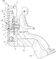
Referring to FIG. 1, there is shown a perspective view of a massage device using acoustic pressure according to an embodiment of the present invention.
Referring to the drawings, the massaging device using the acoustic pressure of the present invention is configured in the form of a chair, and in order to stimulate the meridians, menstrual blood, etc. of the body constituting the human body, It can be a chair-like massager, or it can also be in a different form.
As shown in the figure, the apparatus of the present invention is composed of a
The
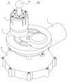
FIG. 2 is a schematic sectional view of one side of a massage device according to an embodiment of the present invention, and FIG. 3 is a schematic perspective view of a vibration and rotation generating part of an embodiment of the present invention.
In the present invention, two vibration generating and rotation generating units A are provided on the left and right sides of the
The support frame (2) is provided with a vibration generator (3) protruding on both sides. The apparatus of the present invention is a device for generating a driving force for raising or lowering the vibration and rotation generating section A and includes a normal and
The conveying means includes a lifting support 5 installed transversely to the vibrating and rotating generating portion A and supporting the vibration and rotation generating portion A and lifting or lowering the lifting support 5, An
Specifically, the vibration and rotation generating portion A is raised and lowered by a driving means such as a forward and
The lifting and lowering support 5 is fixed to one side of the chain 9 by
The
The vibration and rotation generating portion A includes a motor 1 for rotating the vibration generating
Referring to FIG. 4, a front view of a massage device according to an embodiment of the present invention is shown.
As shown in the drawings, the device of the present invention can be installed in the buttocks and the legs.
The operation of the present invention thus constructed will be described in detail with reference to FIGS. 1, 2 and 4. The user is able to relieve symptoms such as infertility in the case of a woman by the vibration provided on the back support part, the hip part and the leg part and the massage by the vibration of the rotation generating part 1, To strengthen the erectile power, in addition, the anus (anus) by vibrating to stimulate various anal diseases can be relieved. Further, stimulation of the body's meridians, menstrual blood, or blood vessel blood can be used to relax the muscles of the body, thereby promoting health.
The
That is, when the normal /
The lifting support 5 is lifted and lowered under the control of the
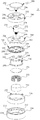
5, there is shown an exploded perspective view of a configuration of a vibration generator according to an embodiment of the present invention.
As shown in the figure, the
In this embodiment, in order to transmit the vibration generated from the
That is, the
Specifically, the
The
The
The
The upper surface of the
The
The
The
The
The
The
The
The
In order to ensure durability, the
Accordingly, the
The connecting
The
The
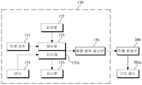
Referring to FIG. 6, a block diagram of a control unit according to an embodiment of the present invention for controlling the massage device of the present invention is shown.
As shown in the figure, the control unit includes a
The sound
Hereinafter, the operation of massage or massage using the apparatus of the present invention will be described.
The user sits in a massage chair to receive massage through the
In the description with reference to the above drawings, the vibration and rotation generating portion of the device of the present invention is applied to the massage chair, but the vibration and rotation generating portion of the present invention can be applied to the bed mattress type and any other forms to be.
According to the present invention described above, the cervical vertebrae or meridians of the human body are rubbed or pressed by a pressure head capable of stimulating the cervical vertebrae or meridians of the human body according to a suitable massage pattern suitable for a disease or body characteristic of the user It is possible to obtain the effect of improving the health by eliminating the fatigue of the body.
While the present invention has been particularly shown and described with reference to exemplary embodiments thereof, it is to be understood that the invention is not limited to the disclosed embodiments, but, on the contrary, It is intended that the present invention cover the modifications and variations of this invention provided they come within the scope of the appended claims and their equivalents.
A: Vibration and rotation generating unit
1: motor 1a: support plate
2: Support frame 3: Vibration generator
3a: pressure means 4: rotating disk
5: lifting
7: Forward rotation motor 8: Shaft
9: Chain 10: Guide ball
11:
12 ': Lower limit switch
100: massage chair 110: body
120: headrest 130: backrest
140: an armrest 150: a control unit
160: leg rest 170: hip rest
Claims (11)
A massaging device main body part having a plurality of vibrating and rotating generating parts vertically movable at positions corresponding to the cervical vertebrae and meridians of a human body; And
And a control unit for controlling the vibration pressure transmitted from the vibration and rotation generating unit to the human body.
Driving means for generating driving force for vertically driving the vibration and rotation generating portion; And
And a conveying unit connected to the driving unit or the vibration and rotation generating unit to move the vibration and rotation generating unit upward and downward.
The conveying means
An upper sprocket installed on the upper side of the lifting supporter so as to be rotatable through a shaft, a lower sprocket installed on the lower side of the lifting supporter, A chain connected between the upper sprocket and the lower sprocket, and a chain connected to both side walls of the support frame to which the lifting support is inserted, the lower sprocket being axially coupled to the driving unit, An upper limit switch provided at an upper end of the guide hole, and a lower limit switch provided at a lower end of the guide hole.
The control unit includes an acoustic pressure supply unit for providing a pressure for generating vibration to the vibration and rotation generating unit, an input unit for inputting a massage time, a massage type, a sensor for detecting a position of a user's shoulder, And outputting a driving signal to the vibration and rotation generating unit based on the data received from the vibration and rotation generating unit.
Wherein the control unit compares the data input through the sensor and the input unit with data stored in a user's symptom clinic stored in its database to provide a massage pattern suitable for a user. Massage device for type massage.
Wherein the massage pattern includes a massage course, a massage time, and a massage intensity.
Wherein the acoustic pressure supply unit comprises a portable memory device in which a sound source is stored and an interface device capable of receiving a sound source from the external sound source generating device.
The vibration-
A cone damper installed in an inner space of the housing and generating vibration in response to a change in acoustic pressure generated from a sound source;
A vibration probe coupled to the vibration generator to be exposed to the outside of the massage device body; And
And a connecting member having one end coupled to the vibration probe and the other end coupled to a center portion of the cone damper of the vibration and rotation generating portion to transmit the vibration generated from the vibration member to the vibration probe. Massage device for rotary massages using pressure.
The vibration-
A body having an upper portion opened and having an upper body formed with a lower body forming an accommodation space therein and a first engagement hole through which the connection member is inserted at the center of the upper surface, part;
A magnetic body installed in the receiving space of the body to generate magnetic force;
A voice coil installed on an outer circumferential surface of the magnetic body in a receiving space of the body;
An upper plate provided on the magnetic body and on the voice coil to induce magnetic force of the magnetic body to be concentrated on the voice coil, the second plate having a first coupling hole corresponding to the first coupling hole and a second coupling hole to which the coupling member is coupled; And
And a third coupling hole in which the coupling member is coupled corresponding to the second coupling hole is formed and is provided at an upper portion of the upper plate and is coupled between the upper and lower bodies and between the magnetic body and the voice coil And the cone damper generating vibrations in a vertical direction by mutual interaction. The massaging device for rotary complex type massage using acoustic pressure.
In the cone damper,
A cone plate formed in a disk shape and generating vibration in a vertical direction; And
And a plurality of dampers extending along the edge of the cone plate in an outwardly curved strip shape and having a hole for screw connection at an end thereof;
Wherein the dampers are coupled to the edge between the upper and lower bodies.
The sensor and the data inputted through the input unit are compared with the data accumulated by the symptom clinic of the user stored in the database, and according to the massage pattern suitable for the user, the vibration and rotation generating unit elevates and lowers the cervical vertebra and meridians And applying a pressure to the massage.
Priority Applications (2)
| Application Number | Priority Date | Filing Date | Title |
|---|---|---|---|
| KR1020140169106A KR20160064868A (en) | 2014-11-28 | 2014-11-28 | Body massage system and Method using sound pressure |
| PCT/KR2015/012885 WO2016085305A1 (en) | 2014-11-28 | 2015-11-27 | Rotation hybrid type massage device using sound pressure, and method therefor |
Applications Claiming Priority (1)
| Application Number | Priority Date | Filing Date | Title |
|---|---|---|---|
| KR1020140169106A KR20160064868A (en) | 2014-11-28 | 2014-11-28 | Body massage system and Method using sound pressure |
Publications (1)
| Publication Number | Publication Date |
|---|---|
| KR20160064868A true KR20160064868A (en) | 2016-06-08 |
Family
ID=56074736
Family Applications (1)
| Application Number | Title | Priority Date | Filing Date |
|---|---|---|---|
| KR1020140169106A KR20160064868A (en) | 2014-11-28 | 2014-11-28 | Body massage system and Method using sound pressure |
Country Status (2)
| Country | Link |
|---|---|
| KR (1) | KR20160064868A (en) |
| WO (1) | WO2016085305A1 (en) |
Cited By (4)
| Publication number | Priority date | Publication date | Assignee | Title |
|---|---|---|---|---|
| KR20190105820A (en) | 2018-03-06 | 2019-09-18 | 주식회사 로하스테크 | Sonic Vibration Unit for Massage Chair |
| KR20210034224A (en) * | 2019-09-20 | 2021-03-30 | (주)에보소닉 | Localized region massage device using sonic vibration and air pressure and sonic vibration device based on virtual reality having the same |
| KR20220126071A (en) * | 2021-03-08 | 2022-09-15 | 주식회사 휴테크산업 | Massage apparatus using sonic wave |
| WO2024025078A1 (en) * | 2022-07-28 | 2024-02-01 | 삼성전자주식회사 | Massage apparatus |
Families Citing this family (1)
| Publication number | Priority date | Publication date | Assignee | Title |
|---|---|---|---|---|
| CN112043584A (en) * | 2019-06-06 | 2020-12-08 | 张勋华 | Acupuncture device |
Citations (5)
| Publication number | Priority date | Publication date | Assignee | Title |
|---|---|---|---|---|
| KR20040092041A (en) | 2003-04-23 | 2004-11-03 | (주)트윈 세이버 | apparatus for compound massage using voice signal as well as low frequency and method of control thereof |
| KR20100082739A (en) | 2010-03-25 | 2010-07-19 | 주식회사 메디니스 | Massage apparatus for chair mounting |
| KR101110871B1 (en) | 2009-06-09 | 2012-02-15 | 주식회사 아롱엘텍 | A Massage Unit for a Head Skin |
| KR20130020540A (en) | 2011-08-17 | 2013-02-27 | 김정배 | A skin massage apparatus using sound signal |
| KR20140003990A (en) | 2012-06-27 | 2014-01-10 | 이영애 | Massaging apparatus |
Family Cites Families (5)
| Publication number | Priority date | Publication date | Assignee | Title |
|---|---|---|---|---|
| JP2003275263A (en) * | 2002-03-22 | 2003-09-30 | Family Kk | Massaging system, control program database and massaging machine |
| KR100537687B1 (en) * | 2003-06-17 | 2005-12-22 | (주)닥터스텍 | Skin care appliance |
| KR200330336Y1 (en) * | 2003-06-19 | 2003-10-17 | 장석우 | Apparatus for massaging in response to sound source and health-care device mounteded thereof |
| KR200388318Y1 (en) * | 2005-02-16 | 2005-06-30 | 선한규 | Sofa type massage machine |
| KR20130116064A (en) * | 2013-10-01 | 2013-10-22 | 복정제형 주식회사 | Apparatus for massaging whole body with a plural of rotational balls |
-
2014
- 2014-11-28 KR KR1020140169106A patent/KR20160064868A/en active IP Right Grant
-
2015
- 2015-11-27 WO PCT/KR2015/012885 patent/WO2016085305A1/en active Application Filing
Patent Citations (5)
| Publication number | Priority date | Publication date | Assignee | Title |
|---|---|---|---|---|
| KR20040092041A (en) | 2003-04-23 | 2004-11-03 | (주)트윈 세이버 | apparatus for compound massage using voice signal as well as low frequency and method of control thereof |
| KR101110871B1 (en) | 2009-06-09 | 2012-02-15 | 주식회사 아롱엘텍 | A Massage Unit for a Head Skin |
| KR20100082739A (en) | 2010-03-25 | 2010-07-19 | 주식회사 메디니스 | Massage apparatus for chair mounting |
| KR20130020540A (en) | 2011-08-17 | 2013-02-27 | 김정배 | A skin massage apparatus using sound signal |
| KR20140003990A (en) | 2012-06-27 | 2014-01-10 | 이영애 | Massaging apparatus |
Cited By (4)
| Publication number | Priority date | Publication date | Assignee | Title |
|---|---|---|---|---|
| KR20190105820A (en) | 2018-03-06 | 2019-09-18 | 주식회사 로하스테크 | Sonic Vibration Unit for Massage Chair |
| KR20210034224A (en) * | 2019-09-20 | 2021-03-30 | (주)에보소닉 | Localized region massage device using sonic vibration and air pressure and sonic vibration device based on virtual reality having the same |
| KR20220126071A (en) * | 2021-03-08 | 2022-09-15 | 주식회사 휴테크산업 | Massage apparatus using sonic wave |
| WO2024025078A1 (en) * | 2022-07-28 | 2024-02-01 | 삼성전자주식회사 | Massage apparatus |
Also Published As
| Publication number | Publication date |
|---|---|
| WO2016085305A1 (en) | 2016-06-02 |
Similar Documents
| Publication | Publication Date | Title |
|---|---|---|
| KR101487323B1 (en) | Vibration device using acoustic pressure and apparatus for stimulating body with it | |
| KR20160064868A (en) | Body massage system and Method using sound pressure | |
| KR20160064866A (en) | Body massage system and Method using sound pressure | |
| RU2648860C2 (en) | Vibration system and method for stimulating human body by creating a proprioceptive resonance | |
| KR101027432B1 (en) | Massage apparatus | |
| KR101496089B1 (en) | Ability bed using sound wave shock | |
| KR20180100280A (en) | Massage chair device using internet of thing or network | |
| KR101537724B1 (en) | Pillow for acupressure of cervical vertebrae | |
| KR101625430B1 (en) | Vibrator with acoustic sounds | |
| KR102404071B1 (en) | Body stimulating system for provide a vibration using acoustic pressure and bone-conduction sound using photoacoustic-based | |
| KR20150008560A (en) | Foot massage in a bed) | |
| KR102316245B1 (en) | Apparatus for stimulating body and method for stimulating the body using the apparatus | |
| KR101595865B1 (en) | Device for relaxation of neck muscle | |
| CN205515443U (en) | Pregnant woman's massage armchair | |
| JP5498609B1 (en) | Massage device | |
| CN203777498U (en) | Lumbar vertebra massager | |
| KR200402733Y1 (en) | Vibrating blood vessel light hyel rock pressure | |
| KR102429622B1 (en) | Massage apparatus having magnetic field supply function | |
| KR200261409Y1 (en) | a ground pressure seat | |
| KR200336724Y1 (en) | A finger-pressure bed | |
| KR102620620B1 (en) | A device for degenerative brain diseases that uses tactile stimulation by acoustic vibration and music by bone conduction | |
| KR102494115B1 (en) | Massage apparatus for providing pulsed electro magnetic field and operation thereof | |
| CN208081477U (en) | A kind of medical massage equipment | |
| CN108926450B (en) | Medical massage bed | |
| KR200345288Y1 (en) | A vibration mechanism for seat that combine spots on the body suitable for acupuncture and stimulus |
Legal Events
| Date | Code | Title | Description |
|---|---|---|---|
| A201 | Request for examination | ||
| E902 | Notification of reason for refusal | ||
| E701 | Decision to grant or registration of patent right |