KR20160062976A - Micro Pulse System, Electrostatic Precipitator Having The Same, and Method for Controlling Micro Pulse System - Google Patents
Micro Pulse System, Electrostatic Precipitator Having The Same, and Method for Controlling Micro Pulse System Download PDFInfo
- Publication number
- KR20160062976A KR20160062976A KR1020140166374A KR20140166374A KR20160062976A KR 20160062976 A KR20160062976 A KR 20160062976A KR 1020140166374 A KR1020140166374 A KR 1020140166374A KR 20140166374 A KR20140166374 A KR 20140166374A KR 20160062976 A KR20160062976 A KR 20160062976A
- Authority
- KR
- South Korea
- Prior art keywords
- voltage
- pulse
- dust collector
- pulse frequency
- current
- Prior art date
Links
Images


Classifications
-
- H—ELECTRICITY
- H03—ELECTRONIC CIRCUITRY
- H03K—PULSE TECHNIQUE
- H03K3/00—Circuits for generating electric pulses; Monostable, bistable or multistable circuits
- H03K3/02—Generators characterised by the type of circuit or by the means used for producing pulses
- H03K3/53—Generators characterised by the type of circuit or by the means used for producing pulses by the use of an energy-accumulating element discharged through the load by a switching device controlled by an external signal and not incorporating positive feedback
-
- B—PERFORMING OPERATIONS; TRANSPORTING
- B03—SEPARATION OF SOLID MATERIALS USING LIQUIDS OR USING PNEUMATIC TABLES OR JIGS; MAGNETIC OR ELECTROSTATIC SEPARATION OF SOLID MATERIALS FROM SOLID MATERIALS OR FLUIDS; SEPARATION BY HIGH-VOLTAGE ELECTRIC FIELDS
- B03C—MAGNETIC OR ELECTROSTATIC SEPARATION OF SOLID MATERIALS FROM SOLID MATERIALS OR FLUIDS; SEPARATION BY HIGH-VOLTAGE ELECTRIC FIELDS
- B03C3/00—Separating dispersed particles from gases or vapour, e.g. air, by electrostatic effect
- B03C3/34—Constructional details or accessories or operation thereof
- B03C3/66—Applications of electricity supply techniques
-
- Y—GENERAL TAGGING OF NEW TECHNOLOGICAL DEVELOPMENTS; GENERAL TAGGING OF CROSS-SECTIONAL TECHNOLOGIES SPANNING OVER SEVERAL SECTIONS OF THE IPC; TECHNICAL SUBJECTS COVERED BY FORMER USPC CROSS-REFERENCE ART COLLECTIONS [XRACs] AND DIGESTS
- Y10—TECHNICAL SUBJECTS COVERED BY FORMER USPC
- Y10S—TECHNICAL SUBJECTS COVERED BY FORMER USPC CROSS-REFERENCE ART COLLECTIONS [XRACs] AND DIGESTS
- Y10S323/00—Electricity: power supply or regulation systems
- Y10S323/901—Starting circuits
Abstract
Description
본 발명은 마이크로 펄스 시스템에 관한 것으로서, 보다 구체적으로 전기 집진장치용 마이크로 펄스 시스템에 관한 것이다.The present invention relates to a micropulse system, and more particularly to a micropulse system for an electrostatic precipitator.
마이크로 펄스 시스템(MPS; Micro Pulse System)은 마이크로초(㎲) 단위의 짧은 폭을 갖는 펄스를 발생시키는 장치로써, 전기 집진장치 또는 탈취 시스템과 같은 환경설비에 적용된다.BACKGROUND ART A micro pulse system (MPS) is a device for generating a pulse having a short width in microseconds (μs), and is applied to an environmental facility such as an electric dust collector or a deodorization system.
마이크로 펄스 시스템이 전기 집진장치에 적용되는 경우, 마이크로 펄스 시스템은 펄스전압을 방전극에 인가하여 방전극을 통해 코로나 방전이 발생되게 함으로써 음이온이 공기 중에 방전되게 하고, 이에 따라 공기중에 인가된 음이온이 공기 중의 분진을 둘러싸서 분진이 (-)전리되도록 한다. 마이크로 펄스 시스템은 직류전압을 집진판에 인가하여 전리된 분진이 집진판으로 이동하게 함으로써, 음이온은 집진판을 통해 다시 전원으로 돌아가게 하고, 음이온을 잃은 분진은 더 이상 집진판에 머물지 못하고 하부로 낙하하여 수집실(미도시)에 수집되도록 한다.When the micropulse system is applied to an electrostatic precipitator, the micropulse system applies a pulse voltage to the discharge electrode to generate a corona discharge through the discharge electrode, thereby discharging the negative ions into the air. As a result, Energize the dust by surrounding the dust. In the micropulse system, a DC voltage is applied to the dust collecting plate to move the ionized dust to the dust collecting plate, so that the negative ions return to the power source through the dust collecting plate. The dust that has lost the negative ions can not stay in the dust collecting plate, (Not shown).
전기 집진장치에 적용되는 마이크로 펄스 시스템의 대표적인 예가 대한민국 공개특허 제10-2012-0064516호에 개시되어 있다.A representative example of a micro-pulse system applied to an electric dust collector is disclosed in Korean Patent Publication No. 10-2012-0064516.
종래의 마이크로 펄스 시스템의 경우, 마이크로 펄스 시스템의 직류전압, 펄스전압, 및 펄스 주파수를 포함하는 운전 파라미터가 미리 정해진 상한치값이 되도록 지속적으로 운전 제어하는 것이 일반적이었다.In the case of the conventional micropulse system, it has been common to continuously control operation so that the operating parameters including the DC voltage, the pulse voltage, and the pulse frequency of the micropulse system become a predetermined upper limit value.
이와 같이, 운전 파라미터들이 미리 정해진 상한치값에 따라 마이크로 펄스시스템을 지속적으로 운전 제어하게 되면 마이크로 펄스 시스템의 전원공급장치에 스트레스 데미지가 발생할 수 있고, 이로 인해 마이크로 펄스 시스템의 수명이 저하될 수 있다는 문제점이 있다.As described above, if the operation control of the micropulse system is continuously controlled according to the predetermined upper limit value, stress damage may occur in the power supply device of the micropulse system and the lifetime of the micropulse system may be reduced .
이외에도, 종래의 마이크로 펄스 시스템의 경우, 직류전압 제어를 위한 직류전압의 검출(Search)이 빈번하게 발생하였던 관계로 전기 집진장치의 집진효율이 저하된다는 문제점도 있다.In addition, in the case of the conventional micropulse system, since the detection of DC voltage for DC voltage control frequently occurs, there is a problem that the dust collection efficiency of the electrostatic precipitator is lowered.
본 발명은 상술한 문제점을 해결하기 위한 것으로서, 전기 집진장치의 래핑(Rapping)여부에 따라 운전을 제어할 수 있는 마이크로 펄스 시스템, 이를 포함하는 전기 집진장치, 및 마이크로 펄스 시스템의 제어 방법을 제공하는 것을 그 기술적 과제로 한다.SUMMARY OF THE INVENTION The present invention provides a micropulse system capable of controlling operation according to whether or not the electrical dust collector is being rapped, an electric dust collector including the same, and a micropulse system control method. As a technical problem.
또한, 본 발명은 직류전압 검출 회수를 최소화할 수 있는 마이크로 펄스 시스템, 이를 포함하는 전기 집진장치, 및 마이크로 펄스 시스템의 제어 방법을 제공하는 것을 다른 기술적 과제로 한다.Another object of the present invention is to provide a micropulse system capable of minimizing the number of DC voltage detection, an electric dust collector including the same, and a control method of a micropulse system.
또한, 본 발명은 마이크로 펄스 시스템의 연속사용으로 인한 스트레스 데미지를 감소시킬 수 있는 마이크로 펄스 시스템, 이를 포함하는 전기 집진장치, 및 마이크로 펄스 시스템의 제어 방법을 제공하는 것을 또 다른 그 기술적 과제로 한다.It is another object of the present invention to provide a micropulse system capable of reducing stress damage due to continuous use of a micropulse system, an electric dust collector including the micropulse system, and a control method of a micropulse system.
또한, 본 발명은 전기 집진장치의 탈진능력을 향상시킬 수 있는 마이크로 펄스 시스템, 이를 포함하는 전기 집진장치, 및 마이크로 펄스 시스템의 제어 방법을 제공하는 것을 또 다른 기술적 과제로 한다.Another object of the present invention is to provide a micropulse system capable of improving the exhausting ability of an electric dust collector, an electric dust collector including the same, and a control method of a micropulse system.
상술한 목적을 달성하기 위한 본 발명의 일 측면에 따른 마이크로 펄스 시스템은, 전기 집진장치에 직류전압을 공급하는 직류전압 공급부; 상기 전기 집진장치에 소정의 펄스 주파수에 따른 펄스전압을 공급하는 펄스전압 공급부; 및 추타를 위해 상기 전기 집진장치로 인가되는 래핑(Rapping) 신호의 온/오프를 모니터링하고, 상기 래핑신호의 온/오프에 따라 상기 전기 집진장치의 운전을 제어하는 제어부를 포함하는 것을 특징으로 한다.According to an aspect of the present invention, there is provided a micropulse system including: a DC voltage supply unit for supplying a DC voltage to an electrostatic precipitator; A pulse voltage supplier for supplying a pulse voltage according to a predetermined pulse frequency to the electric dust collector; And a control unit for monitoring on / off of a rapping signal applied to the electrostatic precipitator for chattering and controlling the operation of the electrostatic precipitator according to on / off of the wrapping signal .
상술한 목적을 달성하기 위한 본 발명의 일 측면에 따른 전기 집진장치는, 방전극 및 집진판을 포함하며, 상기 방전극에 인가되는 직류전압과 상기 집진판에 인가되는 소정의 펄스 주파수에 따른 펄스전압에 따라 동작하여 배가스에 포함된 분진을 제거하는 집진기; 상기 집진기의 동작을 제어하고, 상기 집진기의 추타를 위한 래핑신호를 상기 집진기로 인가하는 PLC(Programmable Logic Controller); 및 상기 직류전압 및 상기 펄스전압을 발생시켜 상기 집진기에 인가하는 마이크로 펄스 시스템을 포함하고, 상기 마이크로 펄스 시스템은, 상기 PLC로부터 상기 래핑 신호의 온/오프 상태를 수신하고, 상기 PLC로부터 상기 래핑 신호의 온/오프 상태를 수신하고, 상기 래핑신호의 온/오프에 따라 상기 집진기의 운전을 제어하는 제어부를 포함하는 것을 특징으로 한다.According to an aspect of the present invention, there is provided an electric dust collecting apparatus including an electric discharge electrode and a dust collecting plate, the electric dust collecting apparatus comprising: A dust collector for removing dust contained in the exhaust gas; A PLC (Programmable Logic Controller) for controlling the operation of the dust collector and applying a lapping signal for the chatter of the dust collector to the dust collector; And a micro pulse system for generating and applying the DC voltage and the pulse voltage to the dust collector, wherein the micropulse system receives the on / off state of the wrapping signal from the PLC, And a control unit for controlling the operation of the dust collector according to on / off of the lapping signal.
상술한 목적을 달성하기 위한 본 발명의 또 다른 측면에 따른 마이크로 펄스 시스템의 제어 방법은, 직류전압을 전기 집진장치에 공급하는 직류전압 공급부와 소정의 펄스 주파수에 따른 펄스전압을 전기 집진장치에 공급하는 펄스전압 공급부를 포함하는 마이크로 펄스 시스템의 제어 방법으로서, 추타를 위해 상기 전기 집진장치로 인가되는 래핑 신호의 온/오프를 모니터링하는 단계; 및 상기 래핑신호의 온/오프에 따라 상기 전기 집진장치의 운전을 제어하는 단계를 포함하는 것을 특징으로 한다.According to another aspect of the present invention, there is provided a control method of a micropulse system, including: supplying a DC voltage to a DC power supply unit and a pulse voltage according to a predetermined pulse frequency to an electrostatic precipitator; The method comprising the steps of: monitoring on / off of a lapping signal applied to the electrostatic precipitator for recollection; And controlling operation of the electric dust collector according to on / off of the wrapping signal.
본 발명에 따르면, 전기 집진장치의 래핑(Rapping) 여부에 따라 펄스 주파수 및 직류전압을 가변적으로 제어할 수 있어 마이크로 펄스 시스템을 보다 효율적으로 운영할 수 있다는 효과가 있다.According to the present invention, it is possible to variably control the pulse frequency and the DC voltage depending on whether the electric dust collector is being rapped or not, thereby enabling the micropulse system to operate more efficiently.
또한, 본 발명에 따르면, 전기 집진장치의 래핑이 수행되는 시간 동안 직류전압을 검출하기 때문에 직류전압의 검출회수를 최소화할 수 있고, 이로 인해 전기 집진장치의 집진효율을 향상시킬 수 있다는 효과가 있다.Further, according to the present invention, since the DC voltage is detected during the lapping period of the electric dust collector, the detection frequency of the DC voltage can be minimized, thereby improving the dust collecting efficiency of the electric dust collector .
또한, 본 발명은 전기 집진장치의 래핑이 수행되는 시간 동안 펄스 주파수를 오프시키기 때문에 펄스 전압의 연속사용으로 인한 스트레스 데미지를 감소시킬 수 있고, 이로 인해 마이크로 펄스 시스템의 수명을 향상시킬 수 있다는 효과가 있다.Further, since the pulse frequency is turned off during the lapping operation of the electric dust collector, it is possible to reduce stress damage due to continuous use of the pulse voltage, thereby improving the lifetime of the micropulse system. have.
또한, 본 발명은 전기 집진장치의 래핑이 수행되는 시간 동안 펄스 주파수를 오프시키기 때문에 전기 집진장치의 탈진능력을 향상시킬 수 있고, 이로 인해 전기 집진장치의 분진배출농도가 법기준치 이하로 유지되게 할 수 있다는 효과가 있다.In addition, since the pulse frequency is turned off during the lapping time of the electric dust collector, it is possible to improve the dust collecting ability of the dust collecting apparatus, thereby keeping the dust concentration of the dust collecting apparatus below the legal standard Can be effective.
도 1은 본 발명의 일 실시예에 따른 전기 집진장치의 구성을 보여주는 도면이다.
도 2는 도 1에 도시된 마이크로 펄스 시스템의 구성을 개략적으로 보여주는 블록도이다.
도 3은 도 2에 도시된 직류전압 조절기의 구성을 개략적으로 보여주는 블록도이다.
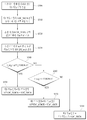
도 4는 본 발명의 일 실시예에 따른 마이크로 펄스 시스템의 제어방법을 보여주는 플로우차트이다.
도 5는 도 4에 도시된 직류전압 제어루틴의 실행방법을 보여주는 플로우차트이다.1 is a view illustrating a configuration of an electric dust collector according to an embodiment of the present invention.
2 is a block diagram schematically illustrating the configuration of the micro-pulse system shown in FIG.
3 is a block diagram schematically showing the configuration of the DC voltage regulator shown in FIG.
4 is a flowchart illustrating a method of controlling a micro-pulse system according to an exemplary embodiment of the present invention.
5 is a flowchart showing a method of executing the DC voltage control routine shown in FIG.
본 명세서에서 서술되는 용어의 의미는 다음과 같이 이해되어야 할 것이다.The meaning of the terms described herein should be understood as follows.
단수의 표현은 문맥상 명백하게 다르게 정의하지 않는 한 복수의 표현을 포함하는 것으로 이해되어야 하고, "제1", "제2" 등의 용어는 하나의 구성요소를 다른 구성요소로부터 구별하기 위한 것으로, 이들 용어들에 의해 권리범위가 한정되어서는 아니 된다.The word " first, "" second," and the like, used to distinguish one element from another, are to be understood to include plural representations unless the context clearly dictates otherwise. The scope of the right should not be limited by these terms.
"포함하다" 또는 "가지다" 등의 용어는 하나 또는 그 이상의 다른 특징이나 숫자, 단계, 동작, 구성요소, 부분품 또는 이들을 조합한 것들의 존재 또는 부가 가능성을 미리 배제하지 않는 것으로 이해되어야 한다.It should be understood that the terms "comprises" or "having" does not preclude the presence or addition of one or more other features, integers, steps, operations, elements, components, or combinations thereof.
"적어도 하나"의 용어는 하나 이상의 관련 항목으로부터 제시 가능한 모든 조합을 포함하는 것으로 이해되어야 한다. 예를 들어, "제1 항목, 제2 항목 및 제 3항목 중에서 적어도 하나"의 의미는 제1 항목, 제2 항목 또는 제3 항목 각각 뿐만 아니라 제1 항목, 제2 항목 및 제3 항목 중에서 2개 이상으로부터 제시될 수 있는 모든 항목의 조합을 의미한다.
It should be understood that the term "at least one" includes all possible combinations from one or more related items. For example, the meaning of "at least one of the first item, the second item and the third item" means not only the first item, the second item or the third item, but also the second item and the second item among the first item, Means any combination of items that can be presented from more than one.
이하, 첨부되는 도면을 참고하여 본 발명의 실시예들에 대해 상세히 설명한다.
Hereinafter, embodiments of the present invention will be described in detail with reference to the accompanying drawings.
<전기 집진장치><Electric dust collector>
도 1은 본 발명의 일 실시예에 따른 전기 집진장치의 구성을 개략적으로 보여주는 도면이다.1 is a schematic view showing a configuration of an electric dust collector according to an embodiment of the present invention.
도 1에 도시된 바와 같이, 본 발명의 일 실시예에 따른 전기 집진장치(100)는, 집진기(110), PLC(120), 마이크로 펄스 시스템(130), 및 HMI(140)를 포함한다.1, an
집진기(110)는 음(-)의 하전을 집진실(미도시)내의 방전극(미도시)에 인가하여 전기적으로 접지부분인 집진판(미도시)과의 전위차에 발생된 정전기력으로 집진기(110)로 유입되는 부유분진을 대전하여 포집한다. 특히, 본 발명에 따른 집진기(110)는 마이크로 펄스 시스템(130)으로부터 직류전압 및 펄스전압을 중첩하여 인가받으로써, 집진판에 포집된 분진을 재비산 없이 효율적으로 탈진할 수 있고, 이를 통해 집진 효율을 향상시킨다.The
여기서, 직류전압은 양극간 고정전계를 구성하여 집진판에 포집된 분진의 재비산을 방지하는 역할을 수행하고, 펄스전압은 부유분진을 대전시켜 집진판으로 이동시키는 역할을 수행한다.Here, the DC voltage forms a fixed electric field between the electrodes to prevent re-scattering of the dust collected on the dust collecting plate, and the pulse voltage charges the floating dust to move it to the dust collecting plate.
집진기(110)는 PLC(Programmable Logic Controller, 120)로부터 입력되는 제어 명령에 따라 동작하고, 집진기(110)의 상태 데이터를 PLC(120)로 전달한다. 집진기(110)의 상태 데이터는 밴드 히터의 동작상태, 분진의 유량, 집진기(110)의 접지상태, 래퍼(Rapper)상태, 및 호퍼상태 등의 데이터를 포함한다.The
일 실시예에 있어서, 집진기(110)는 PLC(120)로부터 집진기(110)의 추타를 위한 래핑(Rapping)신호가 인가되면 인가된 래핑신호에 따라 추타를 수행함으로써 집진판에 포집되어 있는 분진을 탈진하게 된다.In one embodiment, the
래핑이란 집진율을 일정 수준으로 유지하기 위하여 방전극 및 집진판에 부착되어 있는 분진을 제거하는 동작을 의미하는 것으로서, 전하를 띤 입자는 집진판으로 이동하여 포집되고, 일부의 입자는 (+)전하를 띄어 방전극에 부착되기 때문에, 래핑은 집진판 뿐만 아니라 방전극에 대해서도 수행된다.Lapping refers to an operation of removing dust attached to a discharge electrode and a dust collecting plate to maintain a dust collection rate at a certain level. The charged particles move to a dust collecting plate and are collected, and a part of the particles are separated by a positive charge, The lapping is performed not only on the dust collecting plate but also on the discharge electrode.
구체적으로, 집진기(110)는 PLC(120)로부터 입력되는 래핑신호에 따라 추타 또는 진동발생을 일정시간 간격으로 주기적으로 수행하며, 충격력 또는 진동력에 의해 전극 기구를 손상하지 않는 범위 정도의 힘으로 포집층을 덩어리 상태로 낙하시키는 것에 의해 분진의 재비산을 방지하게 된다.Specifically, the
이러한 래핑을 위해 집진기는 래퍼(미도시)를 포함할 수 있다. 일 실시예에 있어서, 래퍼는 전동 기계 타입, 전자 추타 타입, 및 진동 타입으로 구본될 수 있다.For such lapping, the dust collector may include a wrapper (not shown). In one embodiment, the wrapper can be modeled as an electric machine type, an electronic contingency type, and a vibration type.
전동 기계 타입(Motor-Driver Swing Hammer)은, 수평류의 집진기에 사용되며 특히 대형 집진기에 많이 사용된다. 수평으로 배치된 전동기에 의해 구동된 샤프트(Shaft)가 집진판과 직각 방향으로 설치되며, 일정 각도를 갖고 암(Arm)의 선단에 설치된 해머(Hammer)가 샤트프의 회전 운동에 의해 집진판의 모루(Anvil) 을 추타하게 된다. 추타 강도의 조정은 샤프트의 회전속도, 암의 길이와 작동시간으로 조정된다.Motor-Driver Swing Hammer is used in horizontal type dust collectors, especially in large dust collectors. A shaft driven by a motor disposed horizontally is installed in a direction perpendicular to the dust collecting plate and a hammer installed at the tip of the arm at a certain angle is rotated by an anvil of the dust collecting plate Anvil). The adjustment of the chatter strength is controlled by the rotation speed of the shaft, the length of the arm and the operating time.
전자 추타 타입(Magnetic Rapper)은, 전자 코일과 해머로 구성되며, 코일 속에 전류가 흐르면 그 흡인력에 의해 추타를 수행한다. 추타력은 코일에 걸리는 펄스(Pulse)상의 전류의 통전시간과 해머의 스트로크(Stroke) 등을 변화시킴으로써 조정할 수 있다.Magnetic Rapper (Magnetic Rapper) is composed of an electronic coil and a hammer. When a current flows in a coil, it performs a chatter by its attractive force. The excitation force can be adjusted by changing the energization time of the current on the pulse applied to the coil, the stroke of the hammer, and the like.
진동 타입(Vibrator)은, 유도 전동기에 조정 가능한 언발란스드 웨이트(Unbalanced Weight) 를 설치한 방식이다. 진동력은 언발란스드 웨이트의 무게 및 취부 각도를 변화시켜 조정할 수 있다. The vibration type (Vibrator) is an induction motor in which an adjustable unbalanced weight is installed. The vibration power can be adjusted by changing the weight and angle of the unbalanced weight.
PLC(120)는 집진기(110)의 동작을 제어하기 위한 제어명령을 집진기(110)로 입력하고, 집진기(110)로부터 집진기(110)의 상태정보를 수신한다. 또한, PLC(120)는 집진기(110)로부터 수신된 집진기(110)의 상태정보를 HMI(140)로 전달하고, HMI로부터 PLC(120) 또는 집진기(110)의 제어를 위한 명령을 수신한다.The
일 실시예에 있어서, PLC(120)는 집진기(110)의 래핑상태에 따라 마이크로 펄스 시스템(130)을 제어하기 위해, 집진기(110)로 인가되는 래핑신호의 온/오프 상태를 마이크로 펄스 시스템(130)으로 전달한다.In one embodiment, the
마이크로 펄스 시스템(130)은 집진기(110)에 직류전압 및 펄스전압을 중첩하여 인가한다. 이러한 마이크로 펄스 시스템(130)의 구성을 도 2를 참조하여 보다 구체적으로 설명한다.The
도 2는 본 발명의 일 실시예에 따른 마이크로 펄스 시스템의 구성을 개략적으로 보여주는 블록도이다. 2 is a block diagram schematically illustrating a configuration of a micro-pulse system according to an embodiment of the present invention.
도 2에 도시된 바와 같이, 본 발명의 일 실시예에 따른 마이크로 펄스 시스템(130)은 직류전압 공급부(210), 펄스전압 공급부(220), 및 제어부(230)를 포함한다.2, the
직류전압 공급부(210)는 음의 직류전압을 발생시켜 집진실에 포함되어 있는 방전극에 음의 직류전압을 공급한다.The DC
펄스전압 공급부(220)는 집진실의 집진판에 인가되는 펄스전압을 공급하는 것으로서, 직류전압 생성부(미도시), 충전커패시터(미도시), 및 스위칭 소자(미도시)를 포함한다.The pulse
직류전압 생성부는 펄스전압을 위한 양의 직류전압을 생성한다.The DC voltage generating section generates a positive DC voltage for the pulse voltage.
충전커패시터는, 일단은 직류전압 공급부(210)에 연결되고, 타단은 직류전압 생성부에 연결되어 직류전원 공급부(210)로부터 공급되는 음(-)의 직류전압과 직류전압 발생부로부터 공급되는 양(+)의 직류전압을 이용하여 충전을 수행한다. 또한, 충전 커패시터는 충전된 전압을 집진실에 포함된 집진판에 방전함으로서 집진판에 펄스전압이 인가되도록 한다.The charging capacitor is connected to the DC
스위칭 소자는 직류전압 발생부에 연결되는 충전 커패시터의 단자에 연결되어, 충전 커패시터에 충전되어 있는 전압이 소정의 펄스 주파수를 갖는 펄스 형태로 집진판에 방전되도록 한다. 즉, 스위칭 소자는 온오프 동작을 통해 충전 커패시터에 충전되어 있는 전압이 펄스전압 형태로 집진판에 인가되도록 한다.The switching element is connected to the terminal of the charge capacitor connected to the direct current voltage generating part so that the voltage charged in the charge capacitor is discharged to the dust collecting plate in the form of a pulse having a predetermined pulse frequency. That is, the switching element allows the voltage charged in the charge capacitor to be applied to the dust collecting plate in the form of a pulse voltage through the on-off operation.
제어부(230)는 마이크로 펄스 시스템(130)의 직류전압, 펄스전압, 및 펄스 주파수를 포함하는 운전 파라미터를 제어함으로써 마이크로 펄스 시스템(130)의 동작을 제어한다.The
보다 구체적으로, 제어부(230)는 직류전압 공급부(130)로부터 출력되는 직류전압의 상한값(이하, '직류전압 상한값'이라 함), 펄스전압 공급부(130)로부터 출력되는 펄스전압의 상한값(이하, '펄스전압 상한값'이라 함), 및 펄스 주파수의 상한값(이하, '펄스 주파수 상한값'이라 함)을 설정하고, 직류전압 상한값, 펄스전압 상한값, 및 펄스 주파수 상한값에 따라 집진기(110)로 인가하는 직류전압, 펄스전압, 및 펄스 주파수를 조절한다.More specifically, the
특히, 본 발명에 따른 제어부(230)는 PLC(120)로부터 래핑신호의 온오프 여부를 수신하고, 수신된 래핑신호의 온오프 여부에 따라 펄스 주파수 및 직류전압을 조절한다. 이를 위해, 본 발명에 따른 제어부(230)는 도 2에 도시된 같이, 상한값 설정부(232), 펄스 주파수 조절기(234), 펄스전압 조절기(236), 및 직류전압 조절기(238)를 포함한다.In particular, the
상한값 설정부(232)는 미리 정해진 전압-전류 곡선(V-I)을 실행시켜 직류전압 상한값, 펄스전압 상한값, 및 펄스 주파수 상한값을 설정한다. 일 실시예에 있어서, 상한값 설정부(232)는 미리 정해진 전압-전류 곡선(V-I Curve)을 이용하여 직류전압 상한값을 설정하고, 설정된 직류전압 상한값을 N배한 값을 펄스전압 상한값으로 설정할 수 있다. 상한값 설정부(232)는 운전자로부터 입력되는 임의의 주파수값을 펄스 주파수 상한값으로 설정할 수 있다.The upper limit
이외에도, 상한값 설정부(232)는 미리 정해진 직류전류 값(예컨대, 200mA)을 직류전류 상한값으로 설정하고, 아래의 수학식 1을 이용하여 코로나 전류(I-CORONA)를 설정할 수 있다.In addition, the upper limit
![]()
![]()
수학식 1에서, K는 집진판 면적당 추전전류를 의미하고, N은 하전장치의 개수를 의미하며, a는 가중치를 의미한다. 일 실시예에 있어서, a는 1.2로 설정될 수 있다.In Equation (1), K denotes the estimated current per collecting plate area, N denotes the number of the charging devices, and a denotes the weight. In one embodiment, a may be set to 1.2.
펄스 주파수 조절기(234)는 PLC(120)로부터 래핑 신호의 온/오프 여부를 수신하고, 래핑신호의 온/오프에 따라 펄스 주파수 제어루틴을 실행하여 펄스 주파수를 가변시킨다.The
보다 구체적으로, 펄스 주파수 조절기(234)는 래핑신호가 온상태인 것으로 판단되면 집진기(110)로 인가되고 있던 펄스 주파수의 값을 0으로 설정함으로써 펄스 주파수를 오프상태로 가변시킨는 펄스 주파수 제어루틴을 실행한다.More specifically, when it is determined that the lapping signal is in the ON state, the
또한, 펄스 주파수 조절기(234)는 래핑신호가 오프상태인 것으로 판단되면, 펄스 주파수가 기 설정된 펄스 주파수 상한값이 되도록 펄스 주파수를 미리 정해진 비율(RAMP_PRF)만큼 단계적으로 증가시키는 펄스 주파수 제어루틴을 실행한다.Further, when it is determined that the lapping signal is in the off state, the
일 실시예에 있어서, 펄스 주파수 조절기(234)는, 집진기(110)로 인가되고 있는 펄스전압을 모니터링하고, 모니터링 결과 펄스 전압이 기 설정된 초기값(예컨대, 20KV) 이상인 경우, 펄스 주파수 제어 루틴을 실행할 수 있다.In one embodiment, the
펄스 주파수 조절기(134)는 펄스전압 조절기(236)로부터 집진기에 인가되고 있는 펄스전압을 수신함으로써, 현재 집진기(110)로 인가되고 있는 펄스전압을 모니터링할 수 있다.The pulse frequency regulator 134 can monitor the pulse voltage being applied to the
이와 같이, 본 발명은 집진기(110)에 래핑신호가 인가되고 있는 동안 펄스 주파수를 오프상태로 설정하기 때문에, 래핑신호가 인가되고 있는 동안 펄스 전압 공급부(220)를 휴지상태로 운영함으로써 펄스 전압 공급부(220)의 연속사용으로 인한 스트레스 데미지를 감소시킬 수 있게 된다.As described above, since the pulse frequency is set to the OFF state while the wrapping signal is being applied to the
또한, 본 발명은 집진기(110)에 래핑신호가 인가되고 있는 동안 펄스 주파수를 오프상태로 설정하기 때문에, 집진실 내에서 부유분진이 집진판에 포집되는 것을 방지하여 집진기(110)의 탈진능력을 향상시킬 수 있게 된다.Further, since the pulse frequency is set to the OFF state while the lapping signal is being applied to the
펄스전압 조절기(236)는 미리 정해진 펄스전압 제어루틴에 따라 펄스전압을 조절한다. 일 실시예에 있어서, 펄스전압 조절기(236)는 펄스전압 제어루틴에 따라 직류전류의 값 및 집진실의 온도 변화량을 이용하여 펄스전압을 조절할 수 있다. 즉, 펄스전압 조절기(236)는 직류전류의 값이 제1 임계값보다 큰지 여부 및 집진실의 온도 변화량이 제2 임계값보다 큰지 여부를 판단하고, 판단결과에 따라 펄스전압을 펄스전압 상한값 범위 내에서 단계적으로 증가시키거나 감소시킨다.The
직류전압 조절기(138) 래핑신호가 온 상태이고 펄스 주파수 조절기(234)에 의해 펄스 주파수가 오프 상태로 설정된 것으로 판단되면, 직류전압 제어루틴을 실행하여 직류전압을 가변시킨다. 즉, 직류전압 조절기(238)는 래핑신호가 온 되어 펄스 주파수가 오프상태로 설정되면, 미리 정해진 직류전압 제어루틴을 실행함으로써, 집진기(110)의 직류전압 및 직류전류를 검출하고, 검출된 직류전류에 기초하여 집진기(110)에 인가할 직류전압을 가변시킨다.When the DC voltage regulator 138 determines that the wrapping signal is on and the pulse frequency is set to the off state by the
직류전압 조절기(238)의 구성을 도 3을 참조하여 보다 구체적으로 설명한다.The configuration of the
도 3은 본 발명의 일 실시예에 따른 직류전압 조절기의 구성을 개략적으로 보여주는 블록도이다. 도 3에 도시된 바와 같이, 본 발명에 따른 직류전압 조절기(238)는 직류전압 검출부(310), 평균값 산출부(320), 및 전압 설정부(330)를 포함한다.3 is a block diagram schematically illustrating the configuration of a DC voltage regulator according to an embodiment of the present invention. 3, the direct
먼저, 직류전압 검출부(310)는 래핑신호의 상태 및 펄스 주파수의 상태를 판단하고, 래핑신호가 온상태이고 펄스 주파수가 오프상태인 것으로 판단되면, 집진기(110)에 현재 인가되고 있는 제1 직류전압을 검출(Search)한다.First, the DC
평균값 산출부(320)는, 직류전압 검출부(310)에 의해 검출된 제1 직류전압을 미리 정해진 전압 증가분(VDC_SRCH)만큼 증가시켜 제2 직류전압으로 설정한 후, 미리 정해진 시간(SEAR_TIME) 동안 집진기(110)에서 직류전류(IDC)를 검출한다. 평균값 산출부(320)는 미리 정해진 시간이 경과하면, 해당 시간 동안 검출된 직류전류의 평균값을 산출한다.The average
전압 설정부(330)는, 평균값 산출부(320)에 의해 직류전류의 평균값과 상한값설정부(230)에 의해 설정된 코로나 전류(I_CORONA)를 비교하고, 비교 결과에 따라 집진기(110)에 인가할 제3 직류전압을 설정한다.The
보다 구체적으로, 전압 설정부(330)는 직류전류의 평균값이 제1 전류 가중치(제1 전류 가중치는 1보다 큰 실수임)가 반영된 코로나 전류와 비교하고, 비교결과 직류전류의 평균값이 제1 가중치가 반영된 코로나 전류보다 크면, 제2 직류전압에서 제1 전압 가중치(제1 전압 가중치는 1보다 큰 실수임)가 반영된 셋백전압(VDC_STBCK) 및 전압 증가분만큼 감소시킨 값을 제3 직류전압으로 설정한다.More specifically, the
한편, 전압 설정부(330)는, 직류전류의 평균값이 제1 전류 가중치가 반영된 코로나 전류보다 크지 않고 코로나 전류보다 크면, 제2 직류전압에서 제2 전압 가중치(제2 전압 가중치는 1보다 작은 양의 실수임)가 반영된 셋백전압 및 전압 증가분만큼 감소시킨 값을 제3 직류전압으로 설정한다.On the other hand, if the average value of the DC current is not larger than the corona current reflecting the first current weight but larger than the corona current, the
한편, 전압 설정부(330)는, 직류전류의 평균값이 코로나 전류보다 크지 않으면, 제2 직류전압에서 전압 증가분만큼 감소시킨 값을 제3 직류전압의 값으로 설정한다.On the other hand, if the average value of the direct current is not larger than the corona current, the
이와 같이, 본 발명에 따르면, 집진기(110)에서 래핑이 수행되는 시간 동안에만 직류전압을 검출하여 직류전압을 설정하기 때문에, 직류전압의 검출회수를 최소화할 수 있고, 이로 인해 집진기(110)의 집진효율을 향상시킬 수 있게 된다.As described above, according to the present invention, since the DC voltage is detected by detecting the DC voltage only during the lapping period of the
다시 도 1을 참조하면, HMI(Human Machine Interface, 140)는 PLC(120)로부터 집진기(110)의 상태정보 및 PLC(120)의 상태정보를 수신하여 운전자에게 출력하고, 운전자로부터 집진기(110) 및 PLC(120)의 제어를 위한 명령을 수신하여 PLC(120)로 전달한다.1, the HMI (Human Machine Interface) 140 receives the status information of the
또한, HMI(140)는 마이크로 펄스 시스템(130)으로부터 마이크로 펄스 시스템(130)의 상태정보를 수신하여 운전자에게 출력하고, 운전자로부터 마이크로 펄스 시스템(130)의 제어를 위한 명령을 수신하여 마이크로 펄스 시스템(130)으로 전달한다.
The
<마이크로 펄스 시스템의 제어방법>≪ Control method of micro-pulse system >
이하에서는 도 4 내지 도 5를 참조하여 본 발명에 따른 마이크로 펄스 시스템의 제어방법에 대해 설명한다.Hereinafter, a method of controlling the micro-pulse system according to the present invention will be described with reference to FIGS.
도 4는 본 발명의 일 실시예에 따른 마이크로 펄스 시스템의 제어방법을 보여주는 플로우차트이다. 도 4에 도시된 마이크로 펄스 시스템의 제어방법은 도 2에 도시된 제어부에 의해 수행될 수 있다.4 is a flowchart illustrating a method of controlling a micro-pulse system according to an exemplary embodiment of the present invention. The control method of the micropulse system shown in FIG. 4 can be performed by the control unit shown in FIG.
제어부는, 마이크로 펄스 시스템을 미리 정해진 운전 파라미터의 값에 따라 운전한다(S400). 운전 파라미터는 직류전압, 펄스전압, 및 펄스 주파수를 포함하고, 제어부는 각 운전 파라미터들을 미리 정해진 상한값에 따라 조절하면서 마이크로 펄스 시스템을 제어하게 된다.The control unit operates the micro-pulse system in accordance with a predetermined operation parameter value (S400). The operation parameter includes a DC voltage, a pulse voltage, and a pulse frequency, and the control unit controls the micropulse system while adjusting each operation parameter according to a predetermined upper limit value.
다음으로, 제어부는 펄스 전압이 초기값(예컨대, 20KV) 이상이 되는지 여부를 판단하고(S410), 펄스 전압이 초기값 이상이 되면 PLC로부터 수신되는 래핑신호가 온상태인지 여부를 판단한다(S420).Next, the controller determines whether the pulse voltage is equal to or greater than the initial value (e.g., 20 KV) (S410). If the pulse voltage is equal to or greater than the initial value, the controller determines whether the wrapping signal received from the PLC is on ).
S420의 판단결과, 래핑신호가 온상태인 것으로 판단되면 펄스 주파수를 오프상태로 설정하는 펄스 주파수 제어루틴을 실행하고(S430), 래핑신호가 오프 상태인 것으로 판단되면 펄스 주파수가 기 설정된 펄스 주파수 상한값이 되도록 펄스 주파수를 미리 정해진 비율만큼 단계적으로 증가시키는 펄스 주파수 제어 루틴을 실행시킨다(S440).As a result of the determination in S420, if it is determined that the lapping signal is in the ON state, a pulse frequency control routine is performed to set the pulse frequency to OFF state (S430). If it is determined that the lapping signal is in the OFF state, A pulse frequency control routine is performed to stepwise increase the pulse frequency by a predetermined ratio at step S440.
이후, 펄스 주파수가 오프 상태로 되면 집진기의 직류전압 및 직류전류에 기초하여 직류전압을 가변시키기 위한 직류전압 제어루틴을 실행한다(S450). Thereafter, when the pulse frequency is turned off, a DC voltage control routine for varying the DC voltage based on the DC voltage and the DC current of the dust collector is executed (S450).
이하, 도 5를 참조하여 직류전압 제어루틴을 실행방법에 대해 보다 구체적으로 설명한다.Hereinafter, a method for executing the DC voltage control routine will be described in more detail with reference to FIG.
도 5는 본 발명에 따른 직류전압 제어루틴의 실행방법을 보여주는 플로우차트이다.5 is a flowchart showing a method of executing the DC voltage control routine according to the present invention.
먼저, 도 5에 도시된 바와 같이, 제어부는 집진기에 현재 인가되고 있는 제1 직류전압을 검출한다(S500).First, as shown in FIG. 5, the controller detects the first DC voltage currently applied to the dust collector (S500).
이후, 제어부는 S500에서 검출된 제1 직류전압을 미리 정해진 전압 증가분(VDC_SRCH)만큼 증가시켜 제2 직류전압을 설정한다(S510). Thereafter, the controller sets the second DC voltage by increasing the first DC voltage detected in S500 by a predetermined voltage increment (VDC_SRCH) (S510).
이후, 제어부는 소정 시간(SEAR_TIME) 동안 집진기에서 직류전류를 검출하고(S520), 소정 시간이 완료되면 해당 시간 동안 검출된 직류전류의 평균값(I_avg)을 산출한다(S530).Thereafter, the controller detects the DC current in the dust collector for a predetermined period of time (SEAR_TIME) (S520) and calculates the average value I_avg of the DC current detected during the predetermined period of time (S530).
이후, 제어부는 S530에서 산출된 직류전류의 평균값(I_avg)이 제1 전류 가중치(a1)가 승산된 코로나 전류(I_CORONA)보다 큰지 여부를 판단하고(S540), 직류전류의 평균값(I_avg)이 제1 전류 가중치(a1)가 반영된 코로나 전류보다 크면, 제1 직류전압에서 제1 전압 가중치(b1)가 승산된 셋백전압(VDC_STBCK) 및 상기 전압 증가분(VDC_SRCH)만큼 감소시킨 값을 집진기에 인가할 제3 직류전압으로 설정한다(S550).The controller then determines whether the average value I_avg of the DC current calculated in step S530 is greater than the corona current I_CORONA multiplied by the first current weight a1 in step S540. (VDC_STBCK) multiplied by the first voltage weight b1 at the first DC voltage and a value reduced by the voltage increment (VDC_SRCH) to the dust collector if the first current weight a1 is greater than the reflected corona current 3 DC voltage is set (S550).
한편, S540의 판단결과 직류전류의 평균값(I_avg)이 제1 전류 가중치(a1)가 승산된 코로나 전류(I_CORONA)보다 크지 않으면, 제어부는 직류전류의 평균값(I_avg)을 코로나 전류(I_CORONA)와 비교한다(S560).On the other hand, if it is determined in step S540 that the average value I_avg of the DC current is not greater than the corona current I_CORONA multiplied by the first current weight a1, the controller compares the average value I_avg of the DC current with the corona current I_CORONA (S560).
S560의 비교결과, 직류전류의 평균값(I_avg)이 코로나 전류(I_CORONA)보다 크면, 제어부는 제1 직류전압에서 제2 전압 가중치(b2)가 승산된 셋백전압(VDC_STBCK) 및 전압 증가분(VDC_SRCH)만큼 감소시킨 값을 제3 직류전압으로 설정한다(S570).If the average value I_avg of the direct current is greater than the corona current I_CORONA as a result of the comparison of S560, the controller determines that the first DC voltage has the second voltage weight b2 multiplied by the setback voltage VDC_STBCK and the voltage increment VDC_SRCH And sets the reduced value to the third DC voltage (S570).
한편, S560의 판단결과, 직류전류의 평균값(I_avg)이 코로나 전류(I_CORONA)보다 크지 않으면, 제어부는 제2 직류전압에서 전압 증가분(VDC_SRCH)만큼 감소시킨 값을 제3 직류전압으로 설정한다(S580).If it is determined in step S560 that the average value I_avg of the DC current is not greater than the corona current I_CORONA, the controller sets the third DC voltage to a value obtained by decreasing the second DC voltage by the voltage increment VDC_SRCH ).
상술한 마이크로 펄스 시스템의 제어 방법은 다양한 컴퓨터 수단을 이용하여 수행될 수 있는 프로그램 형태로도 구현될 수 있는데, 이때 마이크로 펄스 시스템의 제어 방법을 수행하기 위한 프로그램은 하드 디스크, CD-ROM, DVD, 롬(ROM), 램, 또는 플래시 메모리와 같은 컴퓨터로 판독할 수 있는 기록 매체에 저장된다.The control method of the micro-pulse system may be implemented in a form of a program that can be executed using various computer means. The program for performing the control method of the micro-pulse system may be a hard disk, a CD-ROM, a DVD, Readable recording medium such as ROM, RAM, or flash memory.
본 발명이 속하는 기술분야의 당업자는 상술한 본 발명이 그 기술적 사상이나 필수적 특징을 변경하지 않고서 다른 구체적인 형태로 실시될 수 있다는 것을 이해할 수 있을 것이다.It will be understood by those skilled in the art that the present invention may be embodied in other specific forms without departing from the spirit or essential characteristics thereof.
그러므로, 이상에서 기술한 실시예들은 모든 면에서 예시적인 것이며 한정적인 것이 아닌 것으로 이해해야만 한다. 본 발명의 범위는 상기 상세한 설명보다는 후술하는 특허청구범위에 의하여 나타내어지며, 특허청구범위의 의미 및 범위 그리고 그 등가 개념으로부터 도출되는 모든 변경 또는 변형된 형태가 본 발명의 범위에 포함되는 것으로 해석되어야 한다.It is therefore to be understood that the above-described embodiments are illustrative in all aspects and not restrictive. The scope of the present invention is defined by the appended claims rather than the detailed description and all changes or modifications derived from the meaning and scope of the claims and their equivalents are to be construed as being included within the scope of the present invention do.
100: 전기 집진장치
110: 집진기
120: PLC
130: 마이크로 펄스 시스템
140: HMI
210: 직류전압 공급부
220: 펄스전압 공급부
230: 제어부
232: 상한값 설정부
234: 펄스 주파수 조절기
236: 펄스 전압 조절기
238: 직류전압 조절기100: electric dust collector 110: dust collector
120: PLC 130: Micro-pulse system
140: HMI 210: DC voltage supply unit
220: Pulse voltage supply unit 230:
232: Upper limit value setting unit 234: Pulse frequency adjuster
236: Pulse voltage regulator 238: DC voltage regulator
Claims (16)
상기 전기 집진장치에 소정의 펄스 주파수에 따른 펄스전압을 공급하는 펄스전압 공급부; 및
추타를 위해 상기 전기 집진장치로 인가되는 래핑(Rapping) 신호의 온/오프를 모니터링하고, 상기 래핑신호의 온/오프에 따라 상기 전기 집진장치의 운전을 제어하는 제어부를 포함하는 것을 특징으로 하는 마이크로 펄스 시스템.A DC voltage supply unit for supplying a DC voltage to the electric dust collector;
A pulse voltage supplier for supplying a pulse voltage according to a predetermined pulse frequency to the electric dust collector; And
And a control unit for monitoring on / off of a rapping signal applied to the electric dust collector for controlling the operation of the electric dust collector, and controlling the operation of the electric dust collector according to on / off of the wrapping signal. Pulse system.
상기 제어부는,
상기 래핑신호의 온/오프에 따라 펄스 주파수 제어루틴을 실행하여 상기 펄스 주파수를 가변시키고 직류전압 제어루틴을 실행하여 상기 직류전압을 가변시키는 것을 특징으로 하는 마이크로 펄스 시스템.The method according to claim 1,
Wherein,
Wherein the pulse frequency control routine is executed in accordance with the on / off of the wrapping signal to vary the pulse frequency and execute the DC voltage control routine to vary the DC voltage.
상기 제어부는,
상기 펄스 주파수 제어루틴을 실행하는 펄스 주파수 조절기를 포함하고,
상기 펄스 주파수 제어루틴은, 상기 래핑신호가 온되면 상기 펄스 주파수를 오프상태로 가변시키고, 상기 래핑신호가 오프되면 상기 펄스 주파수가 기 설정된 펄스 주파수 상한값이 되도록 상기 펄스 주파수를 미리 정해진 비율(RAMP_PRF)만큼 단계적으로 증가시키는 것을 특징으로 하는 마이크로 펄스 시스템.3. The method of claim 2,
Wherein,
And a pulse frequency controller for executing the pulse frequency control routine,
Wherein the pulse frequency control routine varies the pulse frequency to an OFF state when the lapping signal is on and sets the pulse frequency to a predetermined ratio (RAMP_PRF) so that the pulse frequency becomes the predetermined pulse frequency upper limit value when the lapping signal is off, Wherein the micro-pulse system comprises:
상기 펄스 주파수 조절기는,
상기 펄스 전압을 모니터링하고, 상기 펄스전압이 기 설정된 초기값 이상인 경우 상기 펄스 주파수 제어 루틴을 실행하는 것을 특징으로 하는 마이크로 펄스 시스템.The method of claim 3,
Wherein the pulse frequency adjuster comprises:
Monitoring the pulse voltage, and executing the pulse frequency control routine when the pulse voltage is equal to or greater than a predetermined initial value.
상기 제어부는,
상기 직류전압 제어루틴을 실행하는 직류전압 조절기를 포함하고,
상기 직류전압 제어루틴은, 상기 래핑신호가 온 되면 상기 전기 집진장치의 직류전압 및 직류전류를 검출하고, 상기 직류전류에 기초하여 상기 전기 집진장치에 인가할 직류전압을 가변시키는 것을 특징으로 하는 마이크로 펄스 시스템.3. The method of claim 2,
Wherein,
And a DC voltage regulator for executing the DC voltage control routine,
Wherein the DC voltage control routine detects a DC voltage and a DC current of the electric dust collector when the wrapping signal is turned on and varies a DC voltage to be applied to the electric dust collector based on the DC current, Pulse system.
상기 직류전압 조절기는,
상기 래핑신호가 온되면 상기 전기 집진장치에 인가되고 있는 제1 직류전압을 검출하는 직류전압 검출부;
상기 검출된 제1 직류전압을 미리 정해진 전압 증가분(VDC_SRCH)만큼 증가시켜 제2 직류전압으로 설정하고, 소정 시간동안 상기 전기 집진장치에서 검출되는 직류전류의 평균값을 산출하는 평균값 산출부; 및
상기 산출된 직류전류의 평균값과 상기 전기 집진장치에 흐르는 코로나 전류(I_CORONA)의 비교 결과에 따라 상기 전기 집진장치에 인가할 직류전압을 가변시키는 전압 설정부를 포함하는 것을 특징으로 하는 마이크로 펄스 시스템.6. The method of claim 5,
The DC voltage regulator includes:
A DC voltage detector for detecting a first DC voltage applied to the electrostatic precipitator when the wrapping signal is turned on;
An average value calculating unit for increasing the detected first DC voltage by a predetermined voltage increment (VDC_SRCH) to a second DC voltage and calculating an average value of the DC current detected by the electric dust collector for a predetermined time; And
And a voltage setting unit for varying a DC voltage to be applied to the electric dust collector according to a result of comparison between an average value of the calculated direct current and a corona current I_CORONA flowing through the electric dust collector.
상기 집진기의 동작을 제어하고, 상기 집진기의 추타를 위한 래핑신호를 상기 집진기로 인가하는 PLC(Programmable Logic Controller); 및
상기 직류전압 및 상기 펄스전압을 발생시켜 상기 집진기에 인가하는 마이크로 펄스 시스템을 포함하고,
상기 마이크로 펄스 시스템은,
상기 PLC로부터 상기 래핑 신호의 온/오프 상태를 수신하고, 상기 래핑신호의 온/오프에 따라 상기 집진기의 운전을 제어하는 제어부를 포함하는 것을 특징으로 하는 전기 집진장치.A dust collector including a discharge electrode and a dust collecting plate and operating according to a DC voltage applied to the discharge electrode and a pulse voltage according to a predetermined pulse frequency applied to the dust collecting plate to remove dust contained in the exhaust gas;
A PLC (Programmable Logic Controller) for controlling the operation of the dust collector and applying a lapping signal for the chatter of the dust collector to the dust collector; And
And a micro-pulse system for generating the DC voltage and the pulse voltage and applying the DC voltage and the pulse voltage to the dust collector,
The micro-
And a control unit for receiving the on / off state of the lapping signal from the PLC and controlling the operation of the dust collector according to on / off of the lapping signal.
상기 제어부는,
상기 래핑신호의 온/오프에 따라 펄스 주파수 제어루틴을 실행하여 상기 펄스 주파수를 가변시키고 직류전압 제어루틴을 실행하여 상기 직류전압을 가변시키는 것을 특징으로 하는 전기 집진장치.8. The method of claim 7,
Wherein,
Wherein the pulse frequency control routine is executed in accordance with the on / off of the wrapping signal to vary the pulse frequency and execute the DC voltage control routine to vary the DC voltage.
상기 제어부는,
상기 래핑신호가 온되면 상기 펄스 주파수를 오프상태로 가변시키고, 상기 래핑신호가 오프되면 상기 펄스 주파수가 기 설정된 펄스 주파수 상한값이 되도록 상기 펄스 주파수를 미리 정해진 비율만큼 단계적으로 증가시키는 펄스 주파수 제어루틴을 실행하고,
상기 펄스 주파수 오프시, 상기 집진기에 인가되고 있는 제1 직류전압을 미리 정해진 전압 증가분만큼 증가시켜 제2 직류전압으로 설정하고, 소정 시간 동안 상기 전기 집진장치에서 검출되는 직류전류의 평균값을 산출하며, 상기 산출된 직류전류의 평균값과 상기 전기 집진장치에 흐르는 코로나 전류의 비교 결과에 따라 상기 전기 집진장치에 인가할 직류전압을 가변시키는 직류전압 제어루틴을 실행하는 것을 특징으로 하는 전기 집진장치.8. The method of claim 7,
Wherein,
A pulse frequency control routine for changing the pulse frequency to an OFF state when the lapping signal is on and increasing the pulse frequency stepwise by a predetermined ratio so that the pulse frequency becomes a predetermined pulse frequency upper limit value when the lapping signal is off, Run,
Wherein the first DC voltage applied to the dust collector is increased by a predetermined voltage increment to set a second DC voltage when the pulse frequency is off and an average value of the DC current detected by the electric dust collector for a predetermined time is calculated, And a DC voltage control routine for varying a DC voltage to be applied to the electric dust collector according to a result of comparison between the average value of the calculated DC current and the corona current flowing through the electric dust collector.
상기 제어부는,
상기 직류전류의 평균값이 제1 전류 가중치(제1 전류 가중치는 1보다 큰 실수임)가 반영된 코로나 전류보다 크면 상기 제2 직류전압에서 제1 전압 가중치(제1 전압 가중치는 1보다 큰 실수임)가 반영된 셋백전압 및 상기 전압 증가분만큼 감소시킨 값을 상기 전기 집진장치에 인가할 제3 직류전압으로 설정하고, 상기 직류전류의 평균값이 상기 제1 전류 가중치가 반영된 코로나 전류보다 크지 않고 상기 코로나 전류보다 크면 상기 제1 직류전압에서 제2 전압 가중치(제2 전압 가중치는 1보다 작은 양의 실수임)가 반영된 셋백전압 및 상기 전압 증가분만큼 감소시킨 값을 상기 제3 직류전압으로 설정하며, 상기 직류전류의 평균값이 상기 코로나 전류보다 크지 않으면 상기 제2 직류전압에서 상기 전압 증가분만큼 감소시킨 값을 상기 제3 직류전압으로 설정하는 것을 특징으로 하는 전기 집진장치.10. The method of claim 9,
Wherein,
If the average value of the DC current is greater than the corona current reflecting the first current weight (the first current weight is a real number greater than 1), the first voltage weight (the first voltage weight is a real number greater than 1) And a third DC voltage to be applied to the electrostatic precipitator, wherein the average value of the DC current is not greater than the corona current reflecting the first current weight, and the average value of the DC current is greater than the corona current And sets the third DC voltage to a setback voltage reflecting the second voltage weight (the second voltage weight is a positive real number smaller than 1) and the value reduced by the voltage increment at the first DC voltage, Is smaller than the corona current, a value obtained by decreasing the second DC voltage by the voltage increment is set to the third DC voltage Wherein the electric dust collecting device is an electric dust collecting device.
추타를 위해 상기 전기 집진장치로 인가되는 래핑 신호의 온/오프를 모니터링하는 단계; 및
상기 래핑신호의 온/오프에 따라 상기 전기 집진장치의 운전을 제어하는 단계를 포함하는 것을 특징으로 하는 마이크로 펄스 시스템의 제어 방법.There is provided a control method of a micropulse system including a DC voltage supply unit for supplying a DC voltage to an electrostatic precipitator and a pulse voltage supply unit for supplying a pulse voltage according to a predetermined pulse frequency to an electrostatic precipitator,
Monitoring on / off of a lapping signal applied to the electrostatic precipitator for a chatter; And
And controlling operation of the electric dust collector according to on / off of the wrapping signal.
상기 제어하는 단계에서,
펄스 주파수 제어루틴을 실행하여 상기 펄스 주파수를 가변시키고 직류전압 제어루틴을 실행하여 상기 직류전압을 가변시키는 것을 특징으로 하는 마이크로 펄스 시스템의 제어 방법.12. The method of claim 11,
In the controlling step,
Wherein the pulse frequency control routine is executed to vary the pulse frequency, and the DC voltage control routine is executed to vary the DC voltage.
상기 제어하는 단계는,
상기 래핑신호가 온되면 상기 펄스 주파수를 오프상태로 가변시키고, 상기 래핑신호가 오프되면 상기 펄스 주파수가 기 설정된 펄스 주파수 상한값이 되도록 상기 펄스 주파수를 미리 정해진 비율만큼 단계적으로 증가시키는 펄스 주파수 제어루틴을 실행하는 단계를 포함하는 것을 특징으로 하는 마이크로 펄스 시스템의 제어 방법.13. The method of claim 12,
Wherein the controlling comprises:
A pulse frequency control routine for changing the pulse frequency to an OFF state when the lapping signal is on and increasing the pulse frequency stepwise by a predetermined ratio so that the pulse frequency becomes a predetermined pulse frequency upper limit value when the lapping signal is off, The method comprising the steps of:
상기 펄스 주파수 오프시, 상기 전기 집진장치의 직류전압 및 직류전류를 검출하고, 상기 직류전류에 기초하여 상기 전기 집진장치에 인가할 직류전압을 가변시키는 직류전압 제어루틴을 실행하는 단계를 더 포함하는 것을 특징으로 하는 마이크로 펄스 시스템의 제어 방법.14. The method of claim 13,
Executing a DC voltage control routine for detecting a DC voltage and a DC current of the electric dust collector when the pulse frequency is off and varying a DC voltage to be applied to the electric dust collector based on the DC current, Wherein the micro-pulse system is a micro-pulse system.
상기 래핑신호의 온/오프를 모니터링 하는 단계 이전에, 상기 펄스 전압을 모니터링하는 단계를 더 포함하고,
상기 펄스 전압이 설정된 초기값 이상인 경우 상기 제어하는 단계를 수행하는 것을 특징으로 하는 마이크로 펄스 시스템의 제어 방법.12. The method of claim 11,
Further comprising monitoring the pulse voltage prior to monitoring the on / off of the wrapping signal,
Wherein the controlling step is performed when the pulse voltage is equal to or greater than a set initial value.
Priority Applications (1)
| Application Number | Priority Date | Filing Date | Title |
|---|---|---|---|
| KR1020140166374A KR101688276B1 (en) | 2014-11-26 | 2014-11-26 | Micro Pulse System, Electrostatic Precipitator Having The Same, and Method for Controlling Micro Pulse System |
Applications Claiming Priority (1)
| Application Number | Priority Date | Filing Date | Title |
|---|---|---|---|
| KR1020140166374A KR101688276B1 (en) | 2014-11-26 | 2014-11-26 | Micro Pulse System, Electrostatic Precipitator Having The Same, and Method for Controlling Micro Pulse System |
Publications (2)
| Publication Number | Publication Date |
|---|---|
| KR20160062976A true KR20160062976A (en) | 2016-06-03 |
| KR101688276B1 KR101688276B1 (en) | 2017-01-02 |
Family
ID=56192263
Family Applications (1)
| Application Number | Title | Priority Date | Filing Date |
|---|---|---|---|
| KR1020140166374A KR101688276B1 (en) | 2014-11-26 | 2014-11-26 | Micro Pulse System, Electrostatic Precipitator Having The Same, and Method for Controlling Micro Pulse System |
Country Status (1)
| Country | Link |
|---|---|
| KR (1) | KR101688276B1 (en) |
Cited By (1)
| Publication number | Priority date | Publication date | Assignee | Title |
|---|---|---|---|---|
| KR20180078964A (en) * | 2016-12-30 | 2018-07-10 | 주식회사 포스코아이씨티 | Electrostatic Precipitator Capable of Varying Output and Method for Controlling That Electrostatic Precipitator |
Citations (4)
| Publication number | Priority date | Publication date | Assignee | Title |
|---|---|---|---|---|
| KR20090127333A (en) * | 2007-03-05 | 2009-12-10 | 알스톰 테크놀러지 리미티드 | A method of controlling the order of rapping the collecting electrode plates of an esp |
| KR20120033187A (en) * | 2010-09-29 | 2012-04-06 | 한국전력공사 | Control system and method for electric precipitator |
| KR101203933B1 (en) * | 2007-03-05 | 2012-11-23 | 알스톰 테크놀러지 리미티드 | A method of estimating the dust load of an esp, and a method and a device of controlling the rapping of an esp |
| KR20140059649A (en) * | 2012-11-08 | 2014-05-16 | 주식회사 포스코아이씨티 | Micro pulse system and method for controlling the same |
-
2014
- 2014-11-26 KR KR1020140166374A patent/KR101688276B1/en active IP Right Grant
Patent Citations (4)
| Publication number | Priority date | Publication date | Assignee | Title |
|---|---|---|---|---|
| KR20090127333A (en) * | 2007-03-05 | 2009-12-10 | 알스톰 테크놀러지 리미티드 | A method of controlling the order of rapping the collecting electrode plates of an esp |
| KR101203933B1 (en) * | 2007-03-05 | 2012-11-23 | 알스톰 테크놀러지 리미티드 | A method of estimating the dust load of an esp, and a method and a device of controlling the rapping of an esp |
| KR20120033187A (en) * | 2010-09-29 | 2012-04-06 | 한국전력공사 | Control system and method for electric precipitator |
| KR20140059649A (en) * | 2012-11-08 | 2014-05-16 | 주식회사 포스코아이씨티 | Micro pulse system and method for controlling the same |
Cited By (1)
| Publication number | Priority date | Publication date | Assignee | Title |
|---|---|---|---|---|
| KR20180078964A (en) * | 2016-12-30 | 2018-07-10 | 주식회사 포스코아이씨티 | Electrostatic Precipitator Capable of Varying Output and Method for Controlling That Electrostatic Precipitator |
Also Published As
| Publication number | Publication date |
|---|---|
| KR101688276B1 (en) | 2017-01-02 |
Similar Documents
| Publication | Publication Date | Title |
|---|---|---|
| CA1172686A (en) | Method of controlling operation of an electrostatic precipitator | |
| CA2497006C (en) | Esp performance optimization control | |
| US9630186B2 (en) | Method and a device for cleaning an electrostatic precipitator | |
| US10259062B2 (en) | Pulse and gap control for electrical discharge machining equipment | |
| EP2172271B1 (en) | A method and a device for controlling the power supplied to an electrostatic precipitator | |
| WO2015114762A1 (en) | Electrostatic precipitator, charge control program for electrostatic precipitator, and charge control method for electrostatic precipitator | |
| JP2013508180A (en) | Spark gap control for electrical discharge machine | |
| EP2078563B1 (en) | Method and device for controlling an electrostatic precipitator | |
| KR101688276B1 (en) | Micro Pulse System, Electrostatic Precipitator Having The Same, and Method for Controlling Micro Pulse System | |
| JP2009039593A (en) | Electric dust collector | |
| KR101547024B1 (en) | Electrostatic Precipitator and Method for Controlling Electrostatic Precipitator | |
| US11229916B2 (en) | Method and system for data capture for electrostatic precipitator control | |
| KR101672583B1 (en) | Micro Pulse System, Method for Controlling The Same, Electrostatic Precipitator Including The Same | |
| KR101261792B1 (en) | Control apparatus and method for electric precipitator | |
| JP7240222B2 (en) | Pulse charging device and its control method, electrostatic precipitator | |
| JPH05200324A (en) | Method for controlling charging of electric precipitator | |
| WO1997041958A1 (en) | Method for controlling an electrostatic precipitator | |
| RU2384370C1 (en) | Method for automatic control of filter supply mode | |
| RU2168368C1 (en) | Method for automatic determination, selection and control of mode of electric power supply of filter | |
| JP3039758B2 (en) | Pulse charged electric precipitator | |
| JPH0199659A (en) | Charge controlling method for pulse charge-type electrostatic precipitator | |
| JPH06254438A (en) | Charge control method for electrical dust controller | |
| JPH05104027A (en) | Operation of electric precipitator | |
| JPH0153106B2 (en) | ||
| JPH05212311A (en) | Operation of electric precipitator |
Legal Events
| Date | Code | Title | Description |
|---|---|---|---|
| A201 | Request for examination | ||
| E902 | Notification of reason for refusal | ||
| AMND | Amendment | ||
| E601 | Decision to refuse application | ||
| X091 | Application refused [patent] | ||
| AMND | Amendment | ||
| X701 | Decision to grant (after re-examination) | ||
| FPAY | Annual fee payment |
Payment date: 20191203 Year of fee payment: 4 |