KR20160057504A - Electroluminescent display device and method of driving the same to compensate for degeneration of pixels - Google Patents
Electroluminescent display device and method of driving the same to compensate for degeneration of pixels Download PDFInfo
- Publication number
- KR20160057504A KR20160057504A KR1020140157528A KR20140157528A KR20160057504A KR 20160057504 A KR20160057504 A KR 20160057504A KR 1020140157528 A KR1020140157528 A KR 1020140157528A KR 20140157528 A KR20140157528 A KR 20140157528A KR 20160057504 A KR20160057504 A KR 20160057504A
- Authority
- KR
- South Korea
- Prior art keywords
- stress
- value
- block
- cumulative
- values
- Prior art date
- Legal status (The legal status is an assumption and is not a legal conclusion. Google has not performed a legal analysis and makes no representation as to the accuracy of the status listed.)
- Granted
Links
Images


Classifications
-
- G—PHYSICS
- G09—EDUCATION; CRYPTOGRAPHY; DISPLAY; ADVERTISING; SEALS
- G09G—ARRANGEMENTS OR CIRCUITS FOR CONTROL OF INDICATING DEVICES USING STATIC MEANS TO PRESENT VARIABLE INFORMATION
- G09G3/00—Control arrangements or circuits, of interest only in connection with visual indicators other than cathode-ray tubes
- G09G3/20—Control arrangements or circuits, of interest only in connection with visual indicators other than cathode-ray tubes for presentation of an assembly of a number of characters, e.g. a page, by composing the assembly by combination of individual elements arranged in a matrix no fixed position being assigned to or needed to be assigned to the individual characters or partial characters
- G09G3/22—Control arrangements or circuits, of interest only in connection with visual indicators other than cathode-ray tubes for presentation of an assembly of a number of characters, e.g. a page, by composing the assembly by combination of individual elements arranged in a matrix no fixed position being assigned to or needed to be assigned to the individual characters or partial characters using controlled light sources
- G09G3/30—Control arrangements or circuits, of interest only in connection with visual indicators other than cathode-ray tubes for presentation of an assembly of a number of characters, e.g. a page, by composing the assembly by combination of individual elements arranged in a matrix no fixed position being assigned to or needed to be assigned to the individual characters or partial characters using controlled light sources using electroluminescent panels
- G09G3/32—Control arrangements or circuits, of interest only in connection with visual indicators other than cathode-ray tubes for presentation of an assembly of a number of characters, e.g. a page, by composing the assembly by combination of individual elements arranged in a matrix no fixed position being assigned to or needed to be assigned to the individual characters or partial characters using controlled light sources using electroluminescent panels semiconductive, e.g. using light-emitting diodes [LED]
- G09G3/3208—Control arrangements or circuits, of interest only in connection with visual indicators other than cathode-ray tubes for presentation of an assembly of a number of characters, e.g. a page, by composing the assembly by combination of individual elements arranged in a matrix no fixed position being assigned to or needed to be assigned to the individual characters or partial characters using controlled light sources using electroluminescent panels semiconductive, e.g. using light-emitting diodes [LED] organic, e.g. using organic light-emitting diodes [OLED]
-
- G—PHYSICS
- G09—EDUCATION; CRYPTOGRAPHY; DISPLAY; ADVERTISING; SEALS
- G09G—ARRANGEMENTS OR CIRCUITS FOR CONTROL OF INDICATING DEVICES USING STATIC MEANS TO PRESENT VARIABLE INFORMATION
- G09G2320/00—Control of display operating conditions
- G09G2320/02—Improving the quality of display appearance
- G09G2320/0233—Improving the luminance or brightness uniformity across the screen
-
- G—PHYSICS
- G09—EDUCATION; CRYPTOGRAPHY; DISPLAY; ADVERTISING; SEALS
- G09G—ARRANGEMENTS OR CIRCUITS FOR CONTROL OF INDICATING DEVICES USING STATIC MEANS TO PRESENT VARIABLE INFORMATION
- G09G2320/00—Control of display operating conditions
- G09G2320/02—Improving the quality of display appearance
- G09G2320/0285—Improving the quality of display appearance using tables for spatial correction of display data
-
- G—PHYSICS
- G09—EDUCATION; CRYPTOGRAPHY; DISPLAY; ADVERTISING; SEALS
- G09G—ARRANGEMENTS OR CIRCUITS FOR CONTROL OF INDICATING DEVICES USING STATIC MEANS TO PRESENT VARIABLE INFORMATION
- G09G2320/00—Control of display operating conditions
- G09G2320/04—Maintaining the quality of display appearance
- G09G2320/043—Preventing or counteracting the effects of ageing
- G09G2320/045—Compensation of drifts in the characteristics of light emitting or modulating elements
-
- G—PHYSICS
- G09—EDUCATION; CRYPTOGRAPHY; DISPLAY; ADVERTISING; SEALS
- G09G—ARRANGEMENTS OR CIRCUITS FOR CONTROL OF INDICATING DEVICES USING STATIC MEANS TO PRESENT VARIABLE INFORMATION
- G09G2360/00—Aspects of the architecture of display systems
- G09G2360/16—Calculation or use of calculated indices related to luminance levels in display data
Landscapes
- Engineering & Computer Science (AREA)
- Physics & Mathematics (AREA)
- Computer Hardware Design (AREA)
- General Physics & Mathematics (AREA)
- Theoretical Computer Science (AREA)
- Control Of Indicators Other Than Cathode Ray Tubes (AREA)
- Control Of El Displays (AREA)
Abstract
전계발광 디스플레이 장치의 구동 방법에 따라서, 디스플레이 패널에 포함되는 복수의 픽셀들을 복수의 행들 및 복수의 열들로 이루어진 복수의 픽셀 블록들로 그룹화한다. 입력 영상 데이터에 기초하여 상기 픽셀 블록들에 포함되는 픽셀들의 열화된 정도를 각각 나타내는 누적 블록 스트레스 값들을 제공한다. 서로 인접한 픽셀 블록들에 대한 상기 누적 블록 스트레스 값들에 기초하여 상기 누적 블록 스트레스 값들을 보정하여 보정 스트레스 값들을 제공한다. 상기 보정 스트레스 값들에 기초하여 상기 입력 영상 데이터를 보정한다. According to a method of driving an electroluminescent display device, a plurality of pixels included in a display panel are grouped into a plurality of pixel blocks including a plurality of rows and a plurality of columns. And provides cumulative block stress values indicating the degree of deterioration of the pixels included in the pixel blocks based on the input image data. And provides the correction stress values by correcting the accumulated block stress values based on the accumulated block stress values for adjacent pixel blocks. And corrects the input image data based on the correction stress values.
Description
본 발명은 디스플레이 장치에 관한 것으로서, 더욱 상세하게는 픽셀들의 열화를 보상하는 전계발광 디스플레이 장치 및 전계발광 디스플레이 장치의 구동 방법에 관한 것이다.The present invention relates to a display device, and more particularly, to an electroluminescent display device and a method of driving an electroluminescent display device that compensate deterioration of pixels.
전계발광 디스플레이 장치는 전자와 정공의 재결합에 의하여 빛을 발생하는 발광 다이오드(LED; light emitting diode) 또는 유기 발광 다이오드(OLED; organic light emitting diode)를 이용하여 빠른 응답 속도와 낮은 소비전력으로 구동될 수 있다. 유기 발광 다이오드는 애노드 전극, 캐소드 전극 및 애노드 전극과 캐소드 전극 사이의 발광층을 포함하며, 애노드 전극으로부터 캐소드 전극으로 흐르는 전류에 따라 발광한다. 전계발광 디스플레이 장치는 각 픽셀의 유기 발광 다이오드를 통하여 흐르는 구동 전류에 따라 발광 휘도가 결정되며, 고휘도 이미지의 경우 저휘도 이미지보다 큰 구동 전류가 요구된다. The electroluminescence display device is driven by a fast response speed and low power consumption by using light emitting diodes (LEDs) or organic light emitting diodes (OLEDs) which generate light by recombination of electrons and holes . The organic light emitting diode includes an anode electrode, a cathode electrode, and a light emitting layer between the anode electrode and the cathode electrode, and emits light according to the current flowing from the anode electrode to the cathode electrode. In the electroluminescence display device, the light emission luminance is determined according to the driving current flowing through the organic light emitting diode of each pixel, and in the case of the high luminance image, a driving current larger than the low luminance image is required.
일반적으로 전계발광 디스플레이 장치에서는 구동 전류에 따라서 픽셀들이 스트레스를 받아서 열화된다. 스트레스를 많이 받은 픽셀일수록 열화가 심해지고 이에 따라 휘도 드롭(drop)이 증가하여 디스플레이 이미지의 품질이 저하되는 문제가 있다.Generally, in an electroluminescence display device, pixels are subjected to stress and deteriorate in accordance with a driving current. The more pixels are subjected to stress, the worse the deterioration becomes, and accordingly, the luminance drop decreases and the display image quality deteriorates.
본 발명의 일 목적은 픽셀들의 열화를 효율적으로 보상할 수 있는 전계발광 디스플레이 장치의 구동 방법을 제공하는 것이다.It is an object of the present invention to provide a method of driving an electroluminescent display device capable of effectively compensating deterioration of pixels.
또한 본 발명의 일 목적은 픽셀들의 열화를 효율적으로 보상할 수 있는 전계발광 디스플레이 장치를 제공하는 것이다.It is another object of the present invention to provide an electroluminescent display device capable of effectively compensating deterioration of pixels.
본 발명의 일 목적을 달성하기 위하여, 본 발명의 실시예들에 따른 전계발광 디스플레이 장치의 구동 방법은, 디스플레이 패널에 포함되는 복수의 픽셀들을 복수의 행들 및 복수의 열들로 이루어진 복수의 픽셀 블록들로 그룹화하는 단계, 입력 영상 데이터에 기초하여 상기 픽셀 블록들에 포함되는 픽셀들의 열화된 정도를 각각 나타내는 누적 블록 스트레스 값들을 제공하는 단계, 서로 인접한 픽셀 블록들에 대한 상기 누적 블록 스트레스 값들에 기초하여 상기 누적 블록 스트레스 값들을 보정하여 보정 스트레스 값들을 제공하는 단계 및 상기 보정 스트레스 값들에 기초하여 상기 입력 영상 데이터를 보정하는 단계를 포함한다.According to an aspect of the present invention, there is provided a method of driving an electroluminescent display device including a plurality of pixels arranged in a plurality of rows and a plurality of columns, , Providing cumulative block stress values, each indicative of the degree of degradation of the pixels included in the pixel blocks based on the input image data, based on the cumulative block stress values for adjacent pixel blocks, Correcting the accumulated block stress values to provide correction stress values, and correcting the input image data based on the correction stress values.
일 실시예에 있어서, 상기 보정 스트레스 값들을 제공하는 단계는, 서로 인접한 픽셀 블록들에 대한 상기 누적 블록 스트레스 값들에 기초하여 상기 픽셀 블록들의 내부의 스트레스 경계 위치를 추정하는 단계 및 상기 스트레스 경계 위치에 기초하여 상기 누적 블록 스트레스 값들을 보정하여 상기 보정 스트레스 값들을 제공하는 단계를 포함할 수 있다.In one embodiment, providing the correction stress values comprises estimating a stress boundary position within the pixel blocks based on the cumulative block stress values for neighboring pixel blocks, And correcting the accumulated block stress values to provide the correction stress values.
일 실시예에 있어서, 상기 보정 스트레스 값들을 제공하는 단계는, 상기 스트레스 경계 위치 부근의 픽셀들에 대한 상기 보정 스트레스 값들이 점진적으로 변화되도록 필터링을 수행하는 단계를 더 포함할 수 있다.In one embodiment, the step of providing the correction stress values may further comprise performing filtering such that the correction stress values for the pixels in the vicinity of the stress boundary position are gradually changed.
일 실시예에 있어서, 상기 누적 블록 스트레스 값들을 제공하는 단계는, 각 프레임의 상기 입력 영상 데이터에 기초하여 상기 픽셀 블록들에 각각 포함되는 픽셀들의 계조 값들의 블록 평균 값들을 계산하는 단계 및 복수의 프레임들에 대하여 상기 블록 평균 값들을 누적하여 상기 누적 블록 스트레스 값들을 저장하는 단계를 포함할 수 있다.In one embodiment, the step of providing the cumulative block stress values may include calculating block average values of tone values of pixels included in each of the pixel blocks based on the input image data of each frame, And accumulating the block average values for the frames to store the accumulated block stress values.
일 실시예에 있어서, 상기 보정 스트레스 값들을 제공하는 단계는, 제1 픽셀 블록의 제1 누적 블록 스트레스 값, 상기 제1 픽셀 블록의 왼쪽에 인접한 제2 픽셀 블록의 제2 누적 블록 스트레스 값 및 상기 제1 픽셀 블록의 오른쪽에 인접한 제3 픽셀 블록의 제3 누적 블록 스트레스 값에 기초하여 상기 제1 픽셀 블록의 보정 스트레스 값을 제공하는 단계를 포함할 수 있다.In one embodiment, the step of providing the correction stress values may include calculating a first cumulative block stress value of the first pixel block, a second cumulative block stress value of the second pixel block adjacent to the left of the first pixel block, And providing a correction stress value of the first pixel block based on a third cumulative block stress value of a third pixel block adjacent to the right of the first pixel block.
일 실시예에 있어서, 상기 제1 픽셀 블록의 보정 스트레스 값을 제공하는 단계는, 상기 제1 누적 블록 스트레스 값, 상기 제2 누적 블록 스트레스 값 및 상기 제3 누적 블록 스트레스 값의 차이 값들을 적어도 하나의 기준 값과 비교하여 상기 누적 블록 스트레스 값들이 증가형 또는 감소형인지 판단하는 단계, 상기 누적 블록 스트레스 값들이 증가형 또는 감소형이라고 판단된 경우, 상기 차이 값들에 기초하여 상기 제1 픽셀 블록의 내부의 스트레스 경계 위치를 추정하는 단계 및 상기 스트레스 경계 위치에 기초하여 상기 제1 누적 블록 스트레스 값을 보정하여 상기 제1 픽셀 블록의 상기 보정 스트레스 값을 제공하는 단계를 포함할 수 있다.In one embodiment, the step of providing the correction stress value of the first pixel block may include calculating at least one difference value between the first cumulative block stress value, the second cumulative block stress value, and the third cumulative block stress value Determining whether the cumulative block stress values are incremental or decremental, comparing the cumulative block stress values with a reference value of the cumulative block stress values, and if the cumulative block stress values are determined to be incremental or decremental, Estimating an internal stress boundary position and correcting the first accumulated block stress value based on the stress boundary position to provide the correction stress value of the first pixel block.
일 실시예에 있어서, 상기 제1 픽셀 블록의 보정 스트레스 값을 제공하는 단계는, 상기 누적 블록 스트레스 값들이 증가형 또는 감소형이 아니라고 판단된 경우, 상기 제1 누적 블록 스트레스 값을 그대로 상기 제1 픽셀 블록의 상기 보정 스트레스 값으로서 제공하는 단계를 더 포함할 수 있다.In one embodiment, the step of providing the correction stress value of the first pixel block may further include the step of, when it is determined that the accumulated block stress values are not incremental or decremental, As the correction stress value of the pixel block.
일 실시예에 있어서, 상기 누적 블록 스트레스 값들이 증가형 또는 감소형인지 판단하는 단계는, 상기 제3 누적 블록 스트레스 값에서 상기 제1 누적 블록 스트레스 값을 뺀 제1 차이 값을 계산하는 단계, 상기 제1 누적 블록 스트레스 값에서 상기 제2 누적 블록 스트레스 값을 뺀 제2 차이 값을 계산하는 단계, 상기 제1 차이 값이 양의 기준 값보다 크고 상기 제2 차이 값이 상기 양의 기준 값보다 큰 경우 상기 누적 블록 스트레스 값들이 증가형이라고 판단하는 단계 및 상기 제1 차이 값이 음의 기준 값보다 작고 상기 제2 차이 값이 상기 음의 기준 값보다 작은 경우 상기 누적 블록 스트레스 값들이 감소형이라고 판단하는 단계를 포함할 수 있다.In one embodiment, determining whether the cumulative block stress values are incremental or decremental comprises: calculating a first difference value by subtracting the first cumulative block stress value from the third cumulative block stress value; Calculating a second difference value by subtracting the second cumulative block stress value from the first cumulative block stress value, calculating the second difference value by subtracting the second cumulative block stress value from the first cumulative block stress value Determining that the cumulative block stress values are incremental and if the first difference value is less than the negative reference value and the second difference value is less than the negative reference value, .
일 실시예에 있어서, 상기 제1 픽셀 블록의 내부의 스트레스 경계 위치를 추정하는 단계는, 상기 제3 누적 블록 스트레스 값에서 상기 제2 누적 블록 스트레스 값을 뺀 제3 차이 값을 계산하는 단계, 상기 제1 차이 값을 상기 제3 차이 값으로 나눈 비례 값을 계산하는 단계 및 상기 비례 값에 기초하여 상기 스트레스 경계 위치를 계산하는 단계를 포함할 수 있다.In one embodiment, estimating the stress boundary position within the first pixel block may include calculating a third difference value by subtracting the second cumulative block stress value from the third cumulative block stress value, Calculating a proportional value dividing the first difference value by the third difference value, and calculating the stress boundary position based on the proportional value.
일 실시예에 있어서, 상기 스트레스 경계 위치에 기초하여 상기 제1 누적 블록 스트레스 값을 보정하여 상기 제1 픽셀 블록의 상기 보정 스트레스 값을 제공하는 단계는, 상기 제1 픽셀 블록에 포함된 픽셀들 중에서 상기 스트레스 경계 위치의 왼쪽에 위치한 픽셀들에 대하여 상기 제2 누적 블록 스트레스 값을 상기 보정 스트레스 값으로서 제공하는 단계 및 상기 제1 픽셀 블록에 포함된 픽셀들 중에서 상기 스트레스 경계 위치의 오른쪽에 위치한 픽셀들에 대하여 상기 제3 누적 블록 스트레스 값을 상기 보정 스트레스 값으로서 제공하는 단계를 포함할 수 있다.In one embodiment, the step of correcting the first cumulative block stress value based on the stress boundary position to provide the correction stress value of the first pixel block comprises: Providing the second cumulative block stress value as the correction stress value for pixels located to the left of the stress boundary location, and calculating a second cumulative block stress value for pixels located to the right of the stress boundary position among the pixels included in the first pixel block And providing the third cumulative block stress value as the correction stress value.
일 실시예에 있어서, 상기 스트레스 경계 위치에 기초하여 상기 제1 누적 블록 스트레스 값을 보정하여 상기 제1 픽셀 블록의 상기 보정 스트레스 값을 제공하는 단계는, 상기 스트레스 경계 위치 부근의 픽셀들에 대하여 상기 보정 스트레스 값들이 점진적으로 변화되도록 필터링을 수행하는 단계를 더 포함할 수 있다.In one embodiment, the step of correcting the first cumulative block stress value based on the stress boundary position to provide the correction stress value of the first pixel block comprises: And performing filtering so that the correction stress values are gradually changed.
일 실시예에 있어서, 상기 보정 스트레스 값들을 제공하는 단계는, 제1 픽셀 블록의 제1 누적 블록 스트레스 값, 상기 제1 픽셀 블록의 왼쪽에 인접한 제2 픽셀 블록의 제2 누적 블록 스트레스 값, 상기 제1 픽셀 블록의 오른쪽에 인접한 제3 픽셀 블록의 제3 누적 블록 스트레스 값, 상기 제1 픽셀 블록의 위쪽에 인접한 제4 픽셀 블록의 제4 누적 블록 스트레스 값 및 상기 제1 픽셀 블록의 아래쪽에 인접한 제5 픽셀 블록의 제5 누적 블록 스트레스 값에 기초하여 상기 제1 픽셀 블록의 보정 스트레스 값을 제공하는 단계를 포함할 수 있다.In one embodiment, the step of providing the correction stress values may include calculating a first cumulative block stress value of the first pixel block, a second cumulative block stress value of the second pixel block adjacent to the left of the first pixel block, A third cumulative block stress value of the third pixel block adjacent to the right of the first pixel block, a fourth cumulative block stress value of the fourth pixel block adjacent to the upper side of the first pixel block, and a fourth cumulative block stress value adjacent to the lower side of the first pixel block And providing a correction stress value of the first pixel block based on a fifth accumulated block stress value of the fifth pixel block.
일 실시예에 있어서, 상기 제1 픽셀 블록의 보정 스트레스 값을 제공하는 단계는, 상기 제1 누적 블록 스트레스 값, 상기 제2 누적 블록 스트레스 값 및 상기 제3 누적 블록 스트레스 값의 행 방향 차이 값들을 적어도 하나의 기준 값과 비교하여 상기 누적 블록 스트레스 값들이 행 방향으로 증가형 또는 감소형인지 판단하는 단계, 상기 제1 누적 블록 스트레스 값, 상기 제4 누적 블록 스트레스 값 및 상기 제5 누적 블록 스트레스 값의 열 방향 차이 값들을 상기 적어도 하나의 기준 값과 비교하여 상기 누적 블록 스트레스 값들이 열 방향으로 증가형 또는 감소형인지 판단하는 단계, 상기 누적 블록 스트레스 값들이 행 방향 또는 열 방향으로 증가형 또는 감소형이라고 판단된 경우, 상기 행 방향 차이 값들 또는 상기 열 방향 차이 값들에 기초하여 상기 제1 픽셀 블록의 내부의 스트레스 경계 위치를 추정하는 단계 및 상기 스트레스 경계 위치에 기초하여 상기 제1 누적 블록 스트레스 값을 보정하여 상기 제1 픽셀 블록의 상기 보정 스트레스 값을 제공하는 단계를 포함할 수 있다.In one embodiment, the step of providing the correction stress value of the first pixel block may include comparing the row direction difference values of the first cumulative block stress value, the second cumulative block stress value, and the third cumulative block stress value Determining whether the cumulative block stress values are incremental or decremental in the row direction by comparing the cumulative block stress value with at least one reference value, comparing the first cumulative block stress value, the fourth cumulative block stress value, Comparing the cumulative block stress values with the at least one reference value to determine whether the cumulative block stress values are incremental or decremental in the column direction, and wherein the cumulative block stress values are incremented or decremented in the row or column direction Type difference values or the column direction difference values, Estimating a stress boundary position within the pixel block, and correcting the first accumulated block stress value based on the stress boundary position to provide the correction stress value of the first pixel block.
일 실시예에 있어서, 상기 누적 블록 스트레스 값들이 행 방향으로 증가형 또는 감소형인지 판단하는 단계는, 상기 제3 누적 블록 스트레스 값에서 상기 제1 누적 블록 스트레스 값을 뺀 제1 행 방향 차이 값을 계산하는 단계, 상기 제1 누적 블록 스트레스 값에서 상기 제2 누적 블록 스트레스 값을 뺀 제2 행 방향 차이 값을 계산하는 단계, 상기 제1 행 방향 차이 값이 양의 기준 값보다 크고 상기 제2 행 방향 차이 값이 상기 양의 기준 값보다 큰 경우 상기 누적 블록 스트레스 값들이 행 방향으로 증가형이라고 판단하는 단계 및 상기 제1 행 방향 차이 값이 음의 기준 값보다 작고 상기 제2 행 방향 차이 값이 상기 음의 기준 값보다 작은 경우 상기 누적 블록 스트레스 값들이 행 방향으로 감소형이라고 판단하는 단계를 포함할 수 있다.In one embodiment, the step of determining whether the cumulative block stress values are incremental or decremental in the row direction may include calculating a first cumulative block stress value by subtracting the first cumulative block stress value from a first cumulative block stress value Calculating a second row direction difference value by subtracting the second cumulative block stress value from the first cumulative block stress value, calculating a second row direction difference value by subtracting the second cumulative block stress value from the second cumulative block stress value, Determining that the cumulative block stress values are incremental in a row direction if the direction difference value is greater than the positive reference value and determining that the cumulative block stress values are incremental if the first row direction difference value is less than the negative reference value, And determining that the accumulated block stress values are decremented in the row direction if the absolute value is smaller than the negative reference value.
일 실시예에 있어서, 상기 누적 블록 스트레스 값들이 열 방향으로 증가형 또는 감소형인지 판단하는 단계는, 상기 제5 누적 블록 스트레스 값에서 상기 제1 누적 블록 스트레스 값을 뺀 제1 열 방향 차이 값을 계산하는 단계, 상기 제1 누적 블록 스트레스 값에서 상기 제4 누적 블록 스트레스 값을 뺀 제2 열 방향 차이 값을 계산하는 단계, 상기 제1 열 방향 차이 값이 상기 양의 기준 값보다 크고 상기 제2 열 방향 차이 값이 상기 양의 기준 값보다 큰 경우 상기 누적 블록 스트레스 값들이 열 방향으로 증가형이라고 판단하는 단계 및 상기 제1 열 방향 차이 값이 상기 음의 기준 값보다 작고 상기 제2 열 방향 차이 값이 상기 음의 기준 값보다 작은 경우 상기 누적 블록 스트레스 값들이 열 방향으로 감소형이라고 판단하는 단계를 포함할 수 있다.In one embodiment, the step of determining whether the cumulative block stress values are incremental or decremental in the column direction may include calculating a first columnar difference value obtained by subtracting the first cumulative block stress value from the fifth cumulative block stress value Calculating a second cumulative block stress value by subtracting the fourth cumulative block stress value from the first cumulative block stress value, calculating a second cumulative block stress value by subtracting the fourth cumulative block stress value from the first cumulative block stress value, Determining that the cumulative block stress values are incremental in the column direction if the column direction difference value is greater than the positive reference value and determining that the first column direction difference value is less than the negative reference value, And determining that the accumulated block stress values are decremented in the column direction if the value is smaller than the negative reference value.
일 실시예에 있어서, 상기 제1 픽셀 블록의 내부의 스트레스 경계 위치를 추정하는 단계는, 상기 누적 블록 스트레스 값들이 행 방향으로 증가형 또는 감소형이라고 판단된 경우, 상기 제3 누적 블록 스트레스 값에서 상기 제2 누적 블록 스트레스 값을 뺀 제3 행 방향 차이 값을 계산하는 단계, 상기 제1 행 방향 차이 값을 상기 제3 행 방향 차이 값으로 나눈 행 방향 비례 값을 계산하는 단계 및 상기 행 방향 비례 값에 기초하여 행 방향 스트레스 경계 위치를 계산하는 단계를 포함할 수 있다.In one embodiment, the step of estimating a stress boundary position in the first pixel block may include: estimating a stress boundary position within the first pixel block, when the accumulated block stress values are determined to be incremental or decremental in the row direction, Calculating a third row direction difference value minus the second cumulative block stress value, calculating a row direction proportional value in which the first row direction difference value is divided by the third row direction difference value, And calculating a row direction stress boundary position based on the value of the row direction stress boundary position.
일 실시예에 있어서, 상기 제1 픽셀 블록의 내부의 스트레스 경계 위치를 추정하는 단계는, 상기 누적 블록 스트레스 값들이 열 방향으로 증가형 또는 감소형이라고 판단된 경우, 상기 제5 누적 블록 스트레스 값에서 상기 제4 누적 블록 스트레스 값을 뺀 제3 열 방향 차이 값을 계산하는 단계, 상기 제1 열 방향 차이 값을 상기 제3 열 방향 차이 값으로 나눈 열 방향 비례 값을 계산하는 단계 및 상기 열 방향 비례 값에 기초하여 열 방향 스트레스 경계 위치를 계산하는 단계를 더 포함할 수 있다.In one embodiment, the step of estimating a stress boundary position within the first pixel block may include: calculating a stress boundary position in the first pixel block, Calculating a third column difference value minus the fourth cumulative block stress value, calculating a column direction proportional value of the first column difference value divided by the third column difference value, And calculating a thermal stress boundary position based on the thermal stress boundary position.
일 실시예에 있어서, 상기 스트레스 경계 위치에 기초하여 상기 제1 누적 블록 스트레스 값을 보정하여 상기 제1 픽셀 블록의 상기 보정 스트레스 값을 제공하는 단계는, 상기 누적 블록 스트레스 값들이 행 방향으로 증가형 또는 감소형이라고 판단되고 열 방향으로 증가형 또는 감소형이 아니라고 판단된 경우, 상기 제1 픽셀 블록에 포함된 픽셀들 중에서 상기 행 방향 스트레스 경계 위치의 왼쪽에 위치한 픽셀들에 대하여 상기 제2 누적 블록 스트레스 값을 상기 보정 스트레스 값으로서 제공하고 상기 제1 픽셀 블록에 포함된 픽셀들 중에서 상기 행 방향 스트레스 경계 위치의 오른쪽에 위치한 픽셀들에 대하여 상기 제3 누적 블록 스트레스 값을 상기 보정 스트레스 값으로서 제공하는 단계 및 상기 누적 블록 스트레스 값들이 열 방향으로 증가형 또는 감소형이라고 판단되고 행 방향으로 증가형 또는 감소형이 아니라고 판단된 경우, 상기 제1 픽셀 블록에 포함된 픽셀들 중에서 상기 열 방향 스트레스 경계 위치의 위쪽에 위치한 픽셀들에 대하여 상기 제4 누적 블록 스트레스 값을 상기 보정 스트레스 값으로서 제공하고 상기 제1 픽셀 블록에 포함된 픽셀들 중에서 상기 열 방향 스트레스 경계 위치의 아래쪽에 위치한 픽셀들에 대하여 상기 제5 누적 블록 스트레스 값을 상기 보정 스트레스 값으로서 제공하는 단계를 포함할 수 있다.In one embodiment, the step of correcting the first cumulative block stress value based on the stress boundary position to provide the correction stress value of the first pixel block comprises: Directional stress boundary position among the pixels included in the first pixel block, when it is determined that the first accumulation block is not the enhancement type or the decrease type in the column direction, Providing a stress value as the correction stress value and providing the third accumulated block stress value as the correction stress value for pixels located to the right of the row direction stress boundary position among the pixels included in the first pixel block And the cumulative block stress values are incrementally Wherein the fourth cumulative block stress value is calculated for pixels located above the column direction stress boundary position among the pixels included in the first pixel block, Value as the correction stress value and providing the fifth accumulated block stress value as the correction stress value for pixels located below the column direction stress boundary position among the pixels included in the first pixel block . ≪ / RTI >
일 실시예에 있어서, 상기 누적 블록 스트레스 값들이 행 방향으로도 증가형 또는 감소형이라고 판단되고 열 방향으로도 증가형 또는 감소형이라고 판단된 경우, 상기 제3 누적 블록 스트레스 값과 상기 제2 누적 블록 스트레스 값의 차이의 절대 값과 상기 제5 누적 블록 스트레스 값과 상기 제4 누적 블록 스트레스 값의 차이의 절대 값을 비교하여 행 방향 및 열 방향 중에서 하나의 방향에 대해서만 상기 제1 누적 블록 스트레스 값을 보정하여 상기 제1 픽셀 블록의 상기 보정 스트레스 값을 제공할 수 있다.In one embodiment, when it is determined that the cumulative block stress values are incremental or decremental in the row direction and that the cumulative block stress values are also incremental or decremental in the column direction, the third cumulative block stress value and the second cumulative block stress value The absolute value of the difference between the absolute value of the difference of the block stress value and the absolute value of the difference between the fifth accumulative block stress value and the fourth accumulative block stress value, May be corrected to provide the correction stress value of the first pixel block.
본 발명의 일 목적을 달성하기 위하여, 본 발명의 실시예들에 따른 전계발광 디스플레이 장치는, 복수의 픽셀들을 포함하는 디스플레이 패널, 열화 보상부 및 데이터 드라이버를 포함한다. 상기 열화 보상부는 상기 픽셀들을 복수의 행들 및 복수의 열들로 이루어진 복수의 픽셀 블록들로 그룹화하고, 입력 영상 데이터에 기초하여 상기 픽셀 블록들에 포함되는 픽셀들의 열화된 정도를 각각 나타내는 누적 블록 스트레스 값들을 제공하고, 서로 인접한 픽셀 블록들에 대한 상기 누적 블록 스트레스 값들에 기초하여 상기 누적 블록 스트레스 값들을 보정하여 보정 스트레스 값들을 제공하고, 상기 보정 스트레스 값들에 기초하여 상기 입력 영상 데이터를 보정한다. 상기 데이터 드라이버는 상기 보정된 입력 영상 데이터에 기초하여 상기 픽셀들을 구동한다.In order to accomplish one object of the present invention, an electroluminescent display device according to embodiments of the present invention includes a display panel including a plurality of pixels, a deterioration compensator, and a data driver. The degradation compensation unit groups the pixels into a plurality of pixel blocks including a plurality of rows and a plurality of columns, and generates an accumulated block stress value indicating a deterioration degree of pixels included in the pixel blocks based on the input image data And provides correction stress values by correcting the accumulated block stress values based on the accumulated block stress values for adjacent pixel blocks to correct the input image data based on the correction stress values. The data driver drives the pixels based on the corrected input image data.
본 발명의 실시예들에 따른 전계발광 디스플레이 장치 및 그 구동 방법은, 픽셀들의 그룹화를 통하여 누적 스트레스 값의 데이터 용량을 감소하여 열화 보정 동작을 위한 메모리 용량과 대역폭을 감소함으로써 효율적으로 픽셀들의 열화를 보상할 수 있다.The electroluminescent display device and the driving method thereof according to embodiments of the present invention reduce the data capacity of cumulative stress values through grouping of pixels to reduce the memory capacity and bandwidth for the deterioration correcting operation, You can compensate.
본 발명의 실시예들에 따른 전계발광 디스플레이 장치 및 그 구동 방법은, 픽셀 블록 내의 스트레스 경계 위치를 추정하고 이에 기초하여 누적 블록 스트레스 값들을 보정함으로써 더욱 효율적으로 픽셀들의 열화를 보상할 수 있다.The electroluminescent display device and the driving method thereof according to the embodiments of the present invention can compensate the deterioration of pixels more efficiently by estimating the stress boundary position in the pixel block and correcting the accumulated block stress values based thereon.
도 1은 본 발명의 실시예들에 따른 전계발광 디스플레이 장치의 구동 방법을 나타내는 순서도이다.
도 2는 본 발명의 실시예들에 따른 디스플레이 장치를 나타내는 블록도이다.
도 3은 도 2의 전계발광 디스플레이 장치에 포함되는 열화 보상부를 나타내는 블록도이다.
도 4는 누적 스트레스에 따른 픽셀들의 휘도 드롭을 나타내는 도면이다.
도 5는 도 1의 구동 방법에 포함되는 픽셀들의 그룹화를 설명하기 위한 도면이다.
도 6은 누적 블록 스트레스 값들을 이용한 열화 보상의 경우에 발생할 수 있는 오차를 설명하기 위한 도면이다.
도 7은 본 발명의 일 실시예에 따른 누적 블록 스트레스 값의 보정 방법을 나타내는 순서도이다.
도 8은 누적 블록 스트레스 값들이 증가형인 경우를 나타내는 도면이다.
도 9는 누적 블록 스트레스 값들이 감소형인 경우를 나타내는 도면이다.
도 10은 누적 블록 스트레스 값들이 증가형 또는 감소형인 경우의 보정 스트레스 값을 나타내는 도면이다.
도 11a는 누적 블록 스트레스 값들이 증가형 또는 감소형이 아닌 경우들을 나타내는 도면이다.
도 11b는 누적 블록 스트레스 값들이 증가형 또는 감소형이 아닌 경우의 보정 스트레스 값을 나타내는 도면이다.
도 12는 본 발명의 일 실시예에 따른 필터링을 나타내는 도면이다.
도 13은 본 발명의 일 실시예에 따른 누적 블록 스트레스 값의 이차원적인 보정 방법을 위한 참조 픽셀 블록들을 설명하기 위한 도면이다.
도 14는 본 발명의 일 실시예에 따른 누적 블록 스트레스 값의 이차원적인 보정 방법을 나타내는 순서도이다.
도 15는 누적 블록 스트레스 값들이 행 방향으로 증가형인 경우를 나타내는 도면이다.
도 16은 누적 블록 스트레스 값을 행 방향으로 보정한 경우의 보정 스트레스 값을 나타내는 도면이다.
도 17은 누적 블록 스트레스 값들이 열 방향으로 증가형인 경우를 나타내는 도면이다.
도 18은 누적 블록 스트레스 값을 열 방향으로 보정한 경우의 보정 스트레스 값을 나타내는 도면이다.
도 19는 누적 블록 스트레스 값을 행 방향 및 열 방향으로 보정한 경우의 보정 스트레스 값을 나타내는 도면이다.
도 20은 본 발명의 실시예들에 따른 전자 기기를 나타내는 블록도이다.
도 21은 본 발명의 실시예들에 따른 휴대용 단말기를 나타내는 블록도이다.1 is a flowchart illustrating a method of driving an electroluminescent display device according to embodiments of the present invention.
2 is a block diagram illustrating a display device according to embodiments of the present invention.
3 is a block diagram illustrating a deterioration compensation unit included in the electroluminescent display device of FIG.
4 is a diagram showing a luminance drop of pixels according to cumulative stress.
5 is a diagram for explaining the grouping of pixels included in the driving method of FIG.
FIG. 6 is a diagram for explaining errors that may occur in the case of degradation compensation using accumulated block stress values.
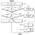
7 is a flowchart illustrating a method of correcting a cumulative block stress value according to an embodiment of the present invention.
8 is a diagram showing the case where the accumulated block stress values are incremental.
9 is a diagram showing a case where the accumulated block stress values are of the reduced type.
10 is a diagram showing a correction stress value when the accumulated block stress values are incremental or decremental.
11A is a diagram showing cases in which cumulative block stress values are not incremental or decremental.
11B is a diagram showing correction stress values when the accumulated block stress values are not incremental or decremental.
12 is a diagram illustrating filtering according to an embodiment of the present invention.
13 is a view for explaining reference pixel blocks for a two-dimensional correction method of a cumulative block stress value according to an embodiment of the present invention.
FIG. 14 is a flowchart illustrating a two-dimensional correction method of a cumulative block stress value according to an embodiment of the present invention.
15 is a diagram showing a case where the accumulated block stress values are incremental in the row direction.
16 is a diagram showing the correction stress value when the accumulated block stress value is corrected in the row direction.
17 is a diagram showing a case where the accumulated block stress values are incremental in the column direction.
18 is a diagram showing the correction stress value when the accumulated block stress value is corrected in the column direction.
19 is a diagram showing the correction stress value when the accumulated block stress value is corrected in the row direction and the column direction.
20 is a block diagram showing an electronic apparatus according to embodiments of the present invention.
21 is a block diagram illustrating a portable terminal according to embodiments of the present invention.
이하, 첨부한 도면들을 참조하여, 본 발명의 바람직한 실시예를 보다 상세하게 설명하고자 한다. 도면상의 동일한 구성요소에 대해서는 동일한 참조부호를 사용하고 동일한 구성요소에 대해서 중복된 설명은 생략한다.Hereinafter, preferred embodiments of the present invention will be described in detail with reference to the accompanying drawings. The same reference numerals are used for the same constituent elements in the drawings and redundant explanations for the same constituent elements are omitted.
도 1은 본 발명의 실시예들에 따른 전계발광 디스플레이 장치의 구동 방법을 나타내는 순서도이다.1 is a flowchart illustrating a method of driving an electroluminescent display device according to embodiments of the present invention.
도 1을 참조하면, 디스플레이 패널에 포함되는 복수의 픽셀들을 복수의 행들 및 복수의 열들로 이루어진 복수의 픽셀 블록들로 그룹화한다(S100). 상기 픽셀들의 그룹화에 대해서는 도 5를 참조하여 후술한다. 입력 영상 데이터에 기초하여 상기 픽셀 블록들에 포함되는 픽셀들의 열화된 정도를 각각 나타내는 누적 블록 스트레스 값들을 제공한다(S300). Referring to FIG. 1, a plurality of pixels included in a display panel are grouped into a plurality of pixel blocks including a plurality of rows and a plurality of columns (S100). The grouping of the pixels will be described later with reference to FIG. And provides cumulative block stress values indicating the degree of deterioration of the pixels included in the pixel blocks based on the input image data (S300).
예를 들어, 각 프레임의 상기 입력 영상 데이터에 기초하여 상기 픽셀 블록들에 각각 포함되는 픽셀들의 계조 값들의 블록 평균 값들을 계산하고, 복수의 프레임들에 대하여 상기 블록 평균 값들을 누적하여 상기 누적 블록 스트레스 값들을 메모리에 저장하는 방식으로 상기 누적 블록 스트레스 값들을 제공할 수 있다. 픽셀들의 그룹화를 통하여 누적 스트레스 값의 데이터 용량을 감소하여 열화 보정 동작을 위한 메모리 용량과 대역폭을 감소함으로써 효율적으로 픽셀들의 열화를 보상할 수 있다.For example, based on the input image data of each frame, block average values of the tone values of the pixels included in each of the pixel blocks are calculated, and the block average values are accumulated for a plurality of frames, The accumulated block stress values may be provided by storing the stress values in a memory. It is possible to effectively compensate the deterioration of pixels by reducing the memory capacity and bandwidth for the deterioration correction operation by reducing the data capacity of the cumulative stress value through grouping of pixels.
서로 인접한 픽셀 블록들에 대한 상기 누적 블록 스트레스 값들에 기초하여 상기 누적 블록 스트레스 값들을 보정하여 보정 스트레스 값들을 제공한다(S500). 상기 보정 스트레스 값들에 기초하여 상기 입력 영상 데이터를 보정한다(S700). 보정된 입력 영상 데이터는 상기 디스플레이 패널의 픽셀들을 구동하기 위하여 데이터 드라이버에 제공된다. The accumulated stress values are corrected based on the accumulated block stress values for adjacent pixel blocks to provide correction stress values (S500). The input image data is corrected based on the correction stress values (S700). The corrected input image data is provided to a data driver for driving pixels of the display panel.
예를 들어, 서로 인접한 픽셀 블록들에 대한 상기 누적 블록 스트레스 값들에 기초하여 상기 픽셀 블록들의 내부의 스트레스 경계 위치를 추정하고, 상기 스트레스 경계 위치에 기초하여 상기 누적 블록 스트레스 값들을 보정하여 상기 보정 스트레스 값들을 제공할 수 있다. 이와 같이, 픽셀 블록 내의 스트레스 경계 위치를 추정하고 이에 기초하여 누적 블록 스트레스 값들을 보정함으로써 더욱 효율적으로 픽셀들의 열화를 보상할 수 있다.For example, estimating a stress boundary position within the pixel blocks based on the accumulated block stress values for adjacent pixel blocks, correcting the accumulated block stress values based on the stress boundary positions, ≪ / RTI > Thus, degradation of pixels can be compensated more efficiently by estimating the stress boundary position in the pixel block and correcting the accumulated block stress values based thereon.
도 2는 본 발명의 실시예들에 따른 디스플레이 장치를 나타내는 블록도이다.2 is a block diagram illustrating a display device according to embodiments of the present invention.
도 2에 도시된 디스플레이 장치(100) 또는 디스플레이 모듈은 전자와 정공의 재결합에 의하여 빛을 발생하는 발광 다이오드(LED; light emitting diode) 또는 유기 발광 다이오드(OLED; organic light emitting diode)를 포함하는 전계발광(electroluminescent) 디스플레이 장치일 수 있다.The
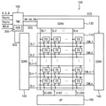
디스플레이 장치(100)는 복수의 픽셀(PX)들을 포함하는 디스플레이 패널(110), 스캔 드라이버(SDRV)(120), 데이터 드라이버(DDRV)(130), 발광 제어 드라이버(EDRV)(140), 타이밍 콘트롤러(150), 열화 보상부(DCB) (degeneration compensating block) (200) 및 디스플레이 장치(100)에 전원 및 전압 신호를 제공하는 전압 공급부(VP)(160)를 포함할 수 있다.The
픽셀(PX)들은 복수의 행들과 복수의 열들의 행렬 형태로 복수의 행 제어 라인들(SL1~SLn), 복수의 데이터 라인들(DL1~DL) 및 복수의 발광 제어 라인들(EML1~EMLn)의 교차부마다 배치될 수 있다. 각각의 픽셀(PX)은 복수의 서브 픽셀들을 포함할 수 있다. 예를 들어, 각각의 픽셀(PX)은 행 방향(X)으로 배열된 R(red) 서브 픽셀, G(green) 서브 픽셀 및 B(blue) 서브 픽셀을 포함할 수 있다. 이 경우, 도 2에 도시된 데이터 라인들(DL1~DLm)의 각각은 3개의 RGB 서브 픽셀들을 각각 구동하기 위한 3개의 신호 라인들을 포함할 수 있다.The pixels PX include a plurality of row control lines SL1 to SLn, a plurality of data lines DL1 to DL and a plurality of emission control lines EML1 to EMLn in a matrix form of a plurality of rows and a plurality of columns, As shown in FIG. Each pixel PX may comprise a plurality of sub-pixels. For example, each pixel PX may comprise an R (red) subpixel, a G (green) subpixel, and a B (blue) subpixel arranged in the row direction X. In this case, each of the data lines DL1 to DLm shown in FIG. 2 may include three signal lines for driving the three RGB sub-pixels, respectively.
픽셀(PX)들은 전압 공급부(160)로부터 양의 전원 전압(ELVDD), 음의 전원 전압(ELVSS), 초기화 전압(VINT) 등의 전압들을 공급받는다. 스캔 드라이버(120)는 행 제어 라인들(SL1~SLn)을 통하여 행 제어 신호들을 행 단위로 픽셀(PX)들에 제공하고, 데이터 드라이버(130)는 복수의 데이터 라인들(DL1~DLm)을 통해 데이터 신호를 열 단위로 픽셀(PX)들에 제공한다. 발광 제어 드라이버(140)는 발광 제어 라인들(EML1~EMLn)을 통해 발광 제어 신호를 행 단위로 픽셀(PX)들에 제공한다.The pixels PX are supplied with voltages such as a positive power supply voltage ELVDD, a negative power supply voltage ELVSS and an initialization voltage VINT from the
타이밍 콘트롤러(150)는 외부에서 전달되는 입력 영상 데이터(R,G,B)를 수신하고 보정된 입력 영상 데이터(DR,DG,DB)를 데이터 드라이버(130)에 전달한다. 또한 타이밍 콘트롤러(150)는 수직동기신호(Vsync), 수평동기신호(Hsync), 및 클럭 신호(MCLK)를 외부로부터 제공 받아 스캔 드라이버(120), 데이터 드라이버(130), 및 발광 제어 드라이버(140)를 제어하기 위한 신호들을 생성하여 각각에 전달한다. 즉 타이밍 콘트롤러(150)는 스캔 드라이버(120)를 제어하는 스캔 구동 제어 신호(SCS), 데이터 드라이버(130)를 제어하는 데이터 구동 제어 신호(DCS), 및 발광 제어 드라이버(140)를 제어하는 발광 구동 제어 신호(ECS)를 각각 생성하여 전달한다. 각각의 픽셀(PX)은 데이터 라인들(DL1~DLm)을 통해 전달되는 데이터 신호에 따라 발광 소자(LED)로 공급되는 구동 전류에 상응하는 휘도의 빛을 발광한다.The
열화 보상부(200)는 픽셀(PX)들을 복수의 행들 및 복수의 열들로 이루어진 복수의 픽셀 블록들로 그룹화하고, 입력 영상 데이터에 기초하여 상기 픽셀 블록들에 포함되는 픽셀(PX)들의 열화된 정도를 각각 나타내는 누적 블록 스트레스 값들을 제공한다. 열화 보상부(200)는 서로 인접한 픽셀 블록들에 대한 상기 누적 블록 스트레스 값들에 기초하여 상기 누적 블록 스트레스 값들을 보정하여 보정 스트레스 값들을 제공하고, 상기 보정 스트레스 값들에 기초하여 상기 입력 영상 데이터를 보정한다. 도 2에는 열화 보상부(200)가 타이밍 콘트롤러(150) 내부에 포함되는 것으로 도시되어 있으나, 열화 보상부(200)는 타이밍 콘트롤러(150)의 외부에 구현될 수도 있다.The
도 3은 도 2의 전계발광 디스플레이 장치에 포함되는 열화 보상부를 나타내는 블록도이다.3 is a block diagram illustrating a deterioration compensation unit included in the electroluminescent display device of FIG.
도 3을 참조하면, 열화 보상부(200)는 샘플링부(SAM)(210), 누적부(ACC)(220), 메모리(MEM)(230), 추출부(EXT)(240), 경계 추정부(BEST)(250), 스트레스 보정부(SCOR)(260) 및 데이터 보정부(DCOR)(270)를 포함할 수 있다.3, the
샘플링부(210)는 각 프레임의 입력 영상 데이터(IDATA)에 기초하여 블록 평균 값(BA)들을 계산하여 제공할 수 있다. 블록 평균 값(BA)들은 픽셀 블록들에 각각 포함되는 픽셀들의 계조 값들의 평균 값들일 수 있다. 누적부(220)는 복수의 프레임들에 대하여 블록 평균 값(BA)을 누적하여 누적 블록 스트레스 값(BST)들을 메모리(230)에 저장한다. The
예를 들어, 누적부(220)는 새로운 프레임에 대한 입력 영상 데이터(IDATA)에 대하여 블록 평균 값(BA)이 제공될 때마다 메모리(230)에 저장된 상응하는 누적 블록 스트레스 값(BST)을 독출하고, 독출된 누적 블록 스트레스 값(BST)에 제공된 블록 평균 값(BA)을 합산한 새로운 누적 블록 스트레스 값(BST)을 이전의 누적 블록 스트레스 값(BST)에 갈음하여 메모리(230)에 저장할 수 있다.For example, the
추출부(240)는 메모리(230)로부터 서로 인접한 픽셀 블록들에 대한 누적 블록 스트레스 값(BST)들을 추출하여 제공할 수 있다. 경계 추정부(250)는 서로 인접한 픽셀 블록들에 대한 누적 블록 스트레스 값(BST)들에 기초하여 픽셀 블록들의 내부의 스트레스 경계 위치(STB)를 추정하여 제공할 수 있다. The
스트레스 보정부(260)는 스트레스 경계 위치(STB)에 기초하여 누적 블록 스트레스 값(BST)들을 보정하여 보정 스트레스 값(CST)들을 제공할 수 있다. 데이터 보정부(270)는 보정 스트레스 값(CST)들에 기초하여 입력 영상 데이터(IDATA)를 보정하여 보정된 입력 영상 데이터(CDATA)를 제공할 수 있다. 보정 스트레스 값(CST)들은 픽셀 단위로 제공될 수 있고, 상응하는 픽셀의 열화된 정도를 나타낼 수 있다. 데이터 보정부(270)는 각 픽셀의 열화 정도에 상응하는 휘도 드롭을 보상할 수 있도록 보정된 입력 영상 데이터(CDATA)를 제공할 수 있다.The
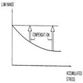
도 4는 누적 스트레스에 따른 픽셀들의 휘도 드롭을 나타내는 도면이다.4 is a diagram showing a luminance drop of pixels according to cumulative stress.
도 4를 참조하면, 픽셀의 누적된 스트레스가 클수록, 즉 픽셀의 열화 정도가 심할수록 동일한 계조의 입력 영상 데이터에 대한 휘도 드롭(luminance drop)이 증가한다. 이러한 휘도 드롭의 차이는 디스플레이 품질을 저하시키므로 누적된 스트레스에 따라서 휘도를 보상하는 것이 요구된다. 즉 도 4에 도시된 바와 같이 누적된 스트레스가 클수록 휘도 보상의 정도를 증가하는 것이 요구된다.Referring to FIG. 4, as the cumulative stress of the pixel increases, that is, as the degree of deterioration of the pixel increases, the luminance drop for the input image data of the same gradation increases. This difference in luminance drop lowers the display quality, and therefore it is required to compensate the luminance according to the accumulated stress. That is, as shown in FIG. 4, as the accumulated stress is increased, it is required to increase the degree of luminance compensation.
픽셀의 누적된 스트레스는 입력 영상 데이터의 휘도, 즉 계조 값과 관련이 있고, 따라서 각 픽셀의 계조 값들에 대한 누적 정보를 통하여 휘도 보상 정도를 예측할 수 있다. 그러나 상기 누적 정보, 즉 스트레스 데이터는 플래시 메모리와 같은 비휘발성 메모리에 저장을 해야 하고, 이를 수 많은 프레임들에 대하여 누적하는 경우에는 데이터 용량이 증가에 따라서 하드웨어 비용의 증가, 메모리 제어시의 대역폭 증가 등의 문제가 발생한다. 이러한 문제를 해결하기 위하여 도 5를 참조하여 설명하는 바와 같은 픽셀들의 그룹화를 이용할 수 있다.The cumulative stress of the pixel is related to the luminance of the input image data, that is, the gray level value, and therefore, the luminance compensation level can be predicted through the accumulated information on the gray level values of each pixel. However, if the cumulative information, that is, the stress data, is stored in a nonvolatile memory such as a flash memory and is accumulated for a large number of frames, an increase in hardware cost, an increase in bandwidth And the like. To solve this problem, it is possible to use grouping of pixels as described with reference to FIG.
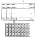
도 5는 도 1의 구동 방법에 포함되는 픽셀들의 그룹화를 설명하기 위한 도면이다.5 is a diagram for explaining the grouping of pixels included in the driving method of FIG.
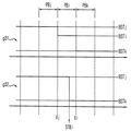
도 5를 참조하면, 디스플레이 패널(110)에 포함되는 복수의 픽셀(PX)들을 복수의 행들(예를 들어, p 행) 및 복수의 열들(예를 들어, s 열)로 이루어진 복수의 픽셀 블록들(PB11~PBps)로 그룹화할 수 있다. 예를 들어, 각각의 픽셀 블록은 도 5에 도시된 바와 같이 64개의 픽셀들을 포함하는 8*8 블록일 수 있다. 각각의 픽셀 블록에 포함되는 픽셀들의 계조 값들을 평균한 블록 평균 값(BA)들을 누적하여 누적 블록 스트레스 값(BST)들을 저장함으로써 스트레스 데이터의 용량을 현저히 감소할 수 있다. 그러나 이러한 압축을 이용한 스트레스 데이터 저장의 경우 스트레스 경계가 정확하게 나타나지 않는다. 따라서 누적 블록 스트레스 값(BST)들을 그대로 이용하여 입력 영상 데이터를 보정하면 휘도 보상의 오류가 심각해질 수 있다.5, a plurality of pixels PX included in the
도 6은 누적 블록 스트레스 값들을 이용한 열화 보상의 경우에 발생할 수 있는 오차를 설명하기 위한 도면이다.FIG. 6 is a diagram for explaining errors that may occur in the case of degradation compensation using accumulated block stress values.
도 6에서 가로축은 픽셀의 위치를 나타내고, X0~X5는 행 방향으로 인접한 픽셀 블록들(PB1~PB5)의 경계 위치를 나타낸다. 그래프 g11은 실제 휘도 드롭의 일 예를 나타내고, 그래프 g12는 상응하는 실제 누적 스트레스를 나타내고, 그래프 g13은 상응하는 누적 블록 스트레스 값들을 나타내고, 그래프 g14는 상응하는 휘도 보상의 오차를 나타낸다. 누적 블록 스트레스 값들은 픽셀 블록 단위로 제공되기 때문에, 스트레스 경계 위치들(STB2, STB4)이 픽셀 블록들(PB1~PB5)의 경계 위치들(X0~X5)과 일치하지 않는 경우에는 휘도 보상의 오차가 발생할 수 있다. In FIG. 6, the abscissa axis indicates the position of the pixel, and X0 through X5 indicate the boundary positions of the adjacent pixel blocks PB1 through PB5 in the row direction. The graph g11 shows an example of the actual luminance drop, the graph g12 shows the corresponding actual cumulative stress, the graph g13 shows the corresponding cumulative block stress values, and the graph g14 shows the error of the corresponding luminance compensation. Since the accumulated block stress values are provided in units of pixel blocks, when the stress boundary positions STB2 and STB4 do not coincide with the boundary positions (X0 to X5) of the pixel blocks PB1 to PB5, May occur.
예를 들어, 도 6에 도시된 바와 같이 휘도 보상이 과도하게 되는 경우들(OFF1, OFF4) 및/또는 휘도 보상이 부족하게 되는 경우들(OFF2, OFF3)이 발생할 수 있다. 본 발명의 실시예들에 따라서 스트레스 경계 위치들(STB2, STB4)을 추정하고, 추정된 스트레스 경계 위치들에 기초하여 누적 블록 스트레스 값들을 보정함으로써 더욱 효율적으로 픽셀들의 열화를 보상할 수 있다.For example, as shown in FIG. 6, cases (OFF1, OFF4) in which the luminance compensation becomes excessive and / or cases (OFF2, OFF3) in which the luminance compensation becomes insufficient may occur. It is possible to more effectively compensate degradation of the pixels by estimating the stress boundary positions STB2 and STB4 according to the embodiments of the present invention and correcting the accumulated block stress values based on the estimated stress boundary positions.
도 7은 본 발명의 일 실시예에 따른 누적 블록 스트레스 값의 보정 방법을 나타내는 순서도이다.7 is a flowchart illustrating a method of correcting a cumulative block stress value according to an embodiment of the present invention.
도 3 및 7을 참조하면, 추출부(240)는 메모리(230)로부터 서로 인접한 픽셀 블록들에 대한 누적 블록 스트레스 값들(BSTi, BSTj, BSTk)을 추출하여 제공한다(S510). 예를 들어, 추출부(240)는 제1 픽셀 블록(PBi)의 제1 누적 블록 스트레스 값(BSTi), 제1 픽셀 블록(PBi)의 왼쪽에 인접한 제2 픽셀 블록(PBj)의 제2 누적 블록 스트레스 값(BSTj) 및 제1 픽셀 블록(PBi)의 오른쪽에 인접한 제3 픽셀 블록(PBk)의 제3 누적 블록 스트레스 값(BSTk)을 추출하여 제공할 수 있다.3 and 7, the extracting
경계 추정부(250)는 제1 누적 블록 스트레스 값(BSTi), 제2 누적 블록 스트레스 값(BSTj) 및 제3 누적 블록 스트레스 값(BSTk)의 차이 값들을 적어도 하나의 기준 값과 비교하여 누적 블록 스트레스 값들(BSTi, BSTj, BSTk)이 증가형 또는 감소형인지 판단할 수 있다. The
예를 들어, 경계 추정부(250)는 제3 누적 블록 스트레스 값(BSTk)에서 제1 누적 블록 스트레스 값(BSTi)을 뺀 제1 차이 값(BSTk-BSTi) 및 제1 누적 블록 스트레스 값(BSTi)에서 제2 누적 블록 스트레스 값(BSTj)을 뺀 제2 차이 값(BSTi-BSTj)을 계산할 수 있다. 경계 추정부(250)는 제1 차이 값(BSTk-BSTi)이 양의 기준 값(TH)보다 크고 제2 차이 값(BSTi-BSTj)이 양의 기준 값(TH)보다 큰 경우(S511: YES) 누적 블록 스트레스 값들(BSTi, BSTj, BSTk)이 증가형이라고 판단(512)할 수 있다. 또한 경계 추정부(250)는 제1 차이 값(BSTk-BSTi)이 음의 기준 값(-TH)보다 작고 제2 차이 값(BSTi-BSTj)이 음의 기준 값(-TH)보다 작은 경우(S513: YES) 누적 블록 스트레스 값들(BSTi, BSTj, BSTk)이 감소형이라고 판단(514)할 수 있다.For example, the
경계 추정부(250)는 누적 블록 스트레스 값들(BSTi, BSTj, BSTk)이 증가형 또는 감소형이라고 판단된 경우(S511: YES 또는 S513: YES), 제1 누적 블록 스트레스 값(BSTi), 제2 누적 블록 스트레스 값(BSTj) 및 제3 누적 블록 스트레스 값(BSTk)의 차이 값들에 기초하여 제1 픽셀 블록(PBi)의 내부의 스트레스 경계 위치(STBi)를 추정한다(S516). 스트레스 보정부(260)는 스트레스 경계 위치(STBi)에 기초하여 제1 누적 블록 스트레스 값(BSTi)을 보정하여 제1 픽셀 블록(PBi)의 보정 스트레스 값(CSTi)을 제공한다(S517). 도 8, 9 및 10을 참조하여 후술하는 바와 같이, 스트레스 보정부(260)는 스트레스 경계 위치(STBi)를 기준으로 제2 누적 블록 스트레스 값(BSTj) 또는 제3 누적 블록 스트레스 값(BSTk)을 제1 픽셀 블록(PBi)의 보정 스트레스 값(CSTi)으로서 제공할 수 있다.The
경계 추정부(250)가 누적 블록 스트레스 값들(BSTi, BSTj, BSTk)이 증가형 또는 감소형이 아니라고 판단한 경우(S511: NO 및 S513: NO), 스트레스 보정부(260)는 제1 누적 블록 스트레스 값(BSTi)을 그대로 제1 픽셀 블록(PBi)의 보정 스트레스 값(CSTi)으로서 제공한다(S515).When the
도 8은 누적 블록 스트레스 값들이 증가형인 경우를 나타내는 도면이고, 도 9는 누적 블록 스트레스 값들이 감소형인 경우를 나타내는 도면이고, 도 10은 누적 블록 스트레스 값들이 증가형 또는 감소형인 경우의 보정 스트레스 값을 나타내는 도면이다.9 is a diagram showing a case where cumulative block stress values are of a decreasing type, and FIG. 10 is a view showing a case where cumulative block stress values are incremental or decremental, Fig.
도 8 및 9에서, 가로축은 픽셀의 위치를 나타내고, Xj 및 Xi는 제1 픽셀 블록(PBi)의 양쪽 경계 위치를 나타낸다. 그래프 g21 및 g31은 누적 블록 스트레스 값들을 나타내고, g22 및 g32는 보정 스트레스 값들을 나타낸다.8 and 9, the horizontal axis represents the position of the pixel, and Xj and Xi represent the boundary positions of the first pixel block PBi. Graphs g21 and g31 show cumulative block stress values, and g22 and g32 show correction stress values.
도 8을 참조하면, 제3 픽셀 블록(PBk)의 제3 누적 블록 스트레스 값(BSTk)은 제1 픽셀 블록(PBi)의 제1 누적 블록 스트레스 값(BSTi)보다 크고 제1 누적 블록 스트레스 값(BSTi)은 제2 픽셀 블록(PBj)의 제2 누적 블록 스트레스 값(BSTj)보다 크다. 도 7을 참조하여 전술한 바와 같이, 경계 추정부(250)는 제1 차이 값(BSTk-BSTi)이 양의 기준 값(TH)보다 크고 제2 차이 값(BSTi-BSTj)이 양의 기준 값(TH)보다 큰 경우 누적 블록 스트레스 값들(BSTi, BSTj, BSTk)이 증가형이라고 판단할 수 있다. 경계 추정부(250)는 이와 같이 누적 블록 스트레스 값들(BSTi, BSTj, BSTk)이 증가형이라고 판단된 경우, 제1 누적 블록 스트레스 값(BSTi), 제2 누적 블록 스트레스 값(BSTj) 및 제3 누적 블록 스트레스 값(BSTk)의 차이 값들에 기초하여 제1 픽셀 블록(PBi)의 내부의 스트레스 경계 위치(STBi)를 추정할 수 있다. 8, the third cumulative block stress value BSTk of the third pixel block PBk is greater than the first cumulative block stress value BSTi of the first pixel block PBi and the first cumulative block stress value BSTk BSTi is larger than the second cumulative block stress value BSTj of the second pixel block PBj. 7, the
예를 들어, 경계 추정부(250)는 제3 누적 블록 스트레스 값(BSTk)에서 제2 누적 블록 스트레스 값(BSTj)을 뺀 제3 차이 값(BSTk-BSTj)을 더 계산하고, 제1 차이 값(BSTk-BSTi)을 제3 차이 값(BSTk-BSTj)으로 나눈 비례 값{(BSTk-BSTi)/ (BSTk-BSTj)}을 계산할 수 있다. 경계 추정부(250)는 비례 값{(BSTk-BSTi)/ (BSTk-BSTj)}에 기초하여 스트레스 경계 위치(STBi)를 계산할 수 있다. 예를 들어, Xj와 STBi 사이의 거리는 비례 값{(BSTk-BSTi)/ (BSTk-BSTj)}에 비례하도록 스트레스 경계 위치(STBi)를 계산할 수 있다.For example, the
도 9를 참조하면, 제3 픽셀 블록(PBk)의 제3 누적 블록 스트레스 값(BSTk)은 제1 픽셀 블록(PBi)의 제1 누적 블록 스트레스 값(BSTi)보다 작고 제1 누적 블록 스트레스 값(BSTi)은 제2 픽셀 블록(PBj)의 제2 누적 블록 스트레스 값(BSTj)보다 작다. 도 7을 참조하여 전술한 바와 같이, 경계 추정부(250)는 제1 차이 값(BSTk-BSTi)이 음의 기준 값(-TH)보다 작고 제2 차이 값(BSTi-BSTj)이 음의 기준 값(-TH)보다 작은 경우 누적 블록 스트레스 값들(BSTi, BSTj, BSTk)이 감소형이라고 판단할 수 있다. 경계 추정부(250)는 이와 같이 누적 블록 스트레스 값들(BSTi, BSTj, BSTk)이 감소형이라고 판단된 경우, 제1 누적 블록 스트레스 값(BSTi), 제2 누적 블록 스트레스 값(BSTj) 및 제3 누적 블록 스트레스 값(BSTk)의 차이 값들에 기초하여 제1 픽셀 블록(PBi)의 내부의 스트레스 경계 위치(STBi)를 추정할 수 있다. 9, the third cumulative block stress value BSTk of the third pixel block PBk is smaller than the first cumulative block stress value BSTi of the first pixel block PBi and the first cumulative block stress value BSTk BSTi is smaller than the second cumulative block stress value BSTj of the second pixel block PBj. 7, the
예를 들어, 경계 추정부(250)는 제3 누적 블록 스트레스 값(BSTk)에서 제2 누적 블록 스트레스 값(BSTj)을 뺀 제3 차이 값(BSTk-BSTj)을 더 계산하고, 제1 차이 값(BSTk-BSTi)을 제3 차이 값(BSTk-BSTj)으로 나눈 비례 값{(BSTk-BSTi)/ (BSTk-BSTj)}을 계산할 수 있다. 경계 추정부(250)는 비례 값{(BSTk-BSTi)/ (BSTk-BSTj)}에 기초하여 스트레스 경계 위치(STBi)를 계산할 수 있다. 예를 들어, Xj와 STBi 사이의 거리는 비례 값{(BSTk-BSTi)/ (BSTk-BSTj)}에 비례하도록 스트레스 경계 위치(STBi)를 계산할 수 있다.For example, the
도 10을 참조하면, 누적 블록 스트레스 값들(BSTi, BSTj, BSTk)이 증가형 또는 감소형이라고 판단된 경우, 스트레스 경계 위치(STBi)를 기준으로 제2 누적 블록 스트레스 값(BSTj) 또는 제3 누적 블록 스트레스 값(BSTk)이 제1 픽셀 블록(PBi)의 보정 스트레스 값(CSTi)으로서 제공될 수 있다. 제1 픽셀 블록(PBi)에 포함된 픽셀들 중에서 스트레스 경계 위치(STBi)의 왼쪽에 위치한 픽셀들에 대하여 제2 누적 블록 스트레스 값(BSTj)을 보정 스트레스 값으로서 제공할 수 있다. 한편, 제1 픽셀 블록(PBi)에 포함된 픽셀들 중에서 스트레스 경계 위치(STBi)의 오른쪽에 위치한 픽셀들에 대하여 제3 누적 블록 스트레스 값(BSTk)을 보정 스트레스 값으로서 제공할 수 있다. 이와 같은 스트레스 경계 위치(STBi)에 기초한 누적 블록 스트레스 값의 보정은 도 8의 그래프 g22 및 도 9의 그래프 g32에 도시한 바와 같다.10, when it is determined that the accumulated block stress values BSTi, BSTj, and BSTk are incremental or decremental, the second cumulative block stress value BSTj or the third cumulative block stress value BSTj, The block stress value BSTk may be provided as the correction stress value CSTi of the first pixel block PBi. The second cumulative block stress value BSTj may be provided as a correction stress value for pixels located to the left of the stress boundary position STBi among the pixels included in the first pixel block PBi. On the other hand, among the pixels included in the first pixel block PBi, the third accumulated block stress value BSTk may be provided as a correction stress value for the pixels located to the right of the stress boundary position STBi. The correction of the accumulated block stress value based on the stress boundary position STBi is as shown in the graph g22 in FIG. 8 and the graph g32 in FIG.
도 11a는 누적 블록 스트레스 값들이 증가형 또는 감소형이 아닌 경우들을 나타내는 도면이고, 도 11b는 누적 블록 스트레스 값들이 증가형 또는 감소형이 아닌 경우의 보정 스트레스 값을 나타내는 도면이다.FIG. 11A is a diagram showing a case where cumulative block stress values are not incremental or decremental types, and FIG. 11B is a diagram showing correction stress values when cumulative block stress values are not incremental or decremental.
그래프 g41을 참조하면, 제3 픽셀 블록(PBk)의 제3 누적 블록 스트레스 값(BSTk)은 제1 픽셀 블록(PBi)의 제1 누적 블록 스트레스 값(BSTi)보다 크고 제1 누적 블록 스트레스 값(BSTi)은 제2 픽셀 블록(PBj)의 제2 누적 블록 스트레스 값(BSTj)보다 크다. 그래프 g41의 경우는 연속한 3개의 픽셀 블록들에 대하여 누적 블록 스트레스 값들이 증가하고 있지만, 제2 차이 값(BSTi-BSTj)이 기준 값(TH)보다 작기 때문에 증가형이라고 판단되지 않는다.Referring to the graph g41, the third cumulative block stress value BSTk of the third pixel block PBk is larger than the first cumulative block stress value BSTi of the first pixel block PBi and the first cumulative block stress value BSTk BSTi is larger than the second cumulative block stress value BSTj of the second pixel block PBj. In the case of the graph g41, the cumulative block stress values are increased for three consecutive pixel blocks, but the second difference value BSTi-BSTj is not smaller than the reference value TH.
그래프 g42를 참조하면, 제3 픽셀 블록(PBk)의 제3 누적 블록 스트레스 값(BSTk)은 제1 픽셀 블록(PBi)의 제1 누적 블록 스트레스 값(BSTi)보다 크고 제1 누적 블록 스트레스 값(BSTi)은 제2 픽셀 블록(PBj)의 제2 누적 블록 스트레스 값(BSTj)보다 작다. 그래프 g42의 경우는 연속한 3개의 픽셀 블록들에 대하여 누적 블록 스트레스 값들이 계속하여 증가 또는 감소하고 있지 않으므로 증가형 또는 감소형이 아니라고 판단된다.Referring to the graph g42, the third cumulative block stress value BSTk of the third pixel block PBk is larger than the first cumulative block stress value BSTi of the first pixel block PBi and the first cumulative block stress value BSTk BSTi is smaller than the second cumulative block stress value BSTj of the second pixel block PBj. In the case of the graph g42, it is judged that the cumulative block stress values do not increase or decrease continuously with respect to three consecutive pixel blocks, and thus are not incremental or decremental.
도 11b를 참조하면, 누적 블록 스트레스 값들(BSTi, BSTj, BSTk)이 증가형 또는 감소형이 아나라고 판단된 경우, 경계 추정부(250)는 제1 픽셀 블록(PBi)의 내부의 스트레스 경계 위치(STBi)를 제공하지 않고, 스트레스 보정부(260)는 제1 누적 블록 스트레스 값(BSTi)을 그대로 제1 픽셀 블록(PBi)의 보정 스트레스 값(CSTi)으로서 제공(S515)할 수 있다.11B, when it is determined that the accumulated block stress values BSTi, BSTj, and BSTk are incremental or decremental, the
도 12는 본 발명의 일 실시예에 따른 필터링을 나타내는 도면이다.12 is a diagram illustrating filtering according to an embodiment of the present invention.
도 12에서 가로축은 픽셀의 위치를 나타내고, X0~X5는 행 방향으로 인접한 픽셀 블록들(PB1~PB5)의 경계 위치를 나타낸다. 그래프 g51은 누적 블록 스트레스 값들의 일 예를 나타내고, 그래프 g52는 상응하는 보정 스트레스 값들을 나타내고, 그래프 g53은 그래프 g52의 보정 스트레스 값들에 대하여 필터링을 수행한 결과를 나타낸다. 이와 같이, 스트레스 경계 위치들(STB2, STB4) 부근의 픽셀들에 대하여 상기 보정 스트레스 값들이 점진적으로 변화되도록 필터링을 수행할 수 있다. 예를 들어, 상기 필터링은 각 픽셀의 보정 스트레스 값을 행 방향으로 인접한 일정한 개수의 픽셀들의 보정 스트레스 값들의 평균 값으로 대체하는 스무딩 필터링(smoothing filtering)일 수 있다.12, the abscissa indicates the position of the pixel, and X0 through X5 indicate the boundary positions of the adjacent pixel blocks PB1 through PB5 in the row direction. The graph g51 shows an example of the accumulated block stress values, the graph g52 shows the corresponding correction stress values, and the graph g53 shows the result of performing the filtering on the correction stress values of the graph g52. In this manner, filtering can be performed so that the correction stress values are gradually changed with respect to the pixels in the vicinity of the stress boundary positions STB2 and STB4. For example, the filtering may be smoothing filtering that replaces the correction stress value of each pixel with an average value of the correction stress values of a predetermined number of adjacent pixels in the row direction.
도 13은 본 발명의 일 실시예에 따른 누적 블록 스트레스 값의 이차원적인 보정 방법을 위한 참조 픽셀 블록들을 설명하기 위한 도면이다.13 is a view for explaining reference pixel blocks for a two-dimensional correction method of a cumulative block stress value according to an embodiment of the present invention.
도 13에는 제1 픽셀 블록(PBi), 제1 픽셀 블록(PBi)의 왼쪽에 인접한 제2 픽셀 블록(PBj), 제1 픽셀 블록(PBi)의 오른쪽에 인접한 제3 픽셀 블록(PBk), 제1 픽셀 블록(PBi)의 위쪽에 인접한 제4 픽셀 블록(PBq) 및 제1 픽셀 블록(PBi)의 아래쪽에 인접한 제5 픽셀 블록(PBr)이 도시되어 있다. 후술하는 바와 같이, 행 방향으로 인접한 2개의 픽셀 블록들(PBj, PBk) 및 열 방향으로 인접한 2개의 픽셀 블록들(PBq, PBr)을 참조하여 가운데 픽셀 블록(PBi)의 누적 블록 스트레스 값(BSTi)을 보정할 수 있다.13 shows a first pixel block PBi, a second pixel block PBj adjacent to the left of the first pixel block PBi, a third pixel block PBk adjacent to the right of the first pixel block PBi, A fourth pixel block PBq adjacent to the upper side of one pixel block PBi and a fifth pixel block PBr adjacent to the lower side of the first pixel block PBi are shown. The cumulative block stress value BSTi of the middle pixel block PBi is calculated by referring to two pixel blocks PBj and PBk adjacent in the row direction and two pixel blocks PBq and PBr adjacent in the column direction, Can be corrected.
도 14는 본 발명의 일 실시예에 따른 누적 블록 스트레스 값의 이차원적인 보정 방법을 나타내는 순서도이다.FIG. 14 is a flowchart illustrating a two-dimensional correction method of a cumulative block stress value according to an embodiment of the present invention.
도 3 및 14를 참조하면, 추출부(240)는 메모리(230)로부터 서로 인접한 픽셀 블록들에 대한 누적 블록 스트레스 값들(BSTi, BSTj, BSTk, BSTq, BSTr)을 추출하여 제공한다(S551). 예를 들어, 추출부(240)는 제1 픽셀 블록(PBi)의 제1 누적 블록 스트레스 값(BSTi), 제1 픽셀 블록(PBi)의 왼쪽에 인접한 제2 픽셀 블록(PBj)의 제2 누적 블록 스트레스 값(BSTj), 제1 픽셀 블록(PBi)의 오른쪽에 인접한 제3 픽셀 블록(PBk)의 제3 누적 블록 스트레스 값(BSTk), 제1 픽셀 블록(PBi)의 위쪽에 인접한 제4 픽셀 블록(PBq)의 제3 누적 블록 스트레스 값(BSTq) 및 제1 픽셀 블록(PBi)의 아래쪽에 인접한 제5 픽셀 블록(PBr)의 제5 누적 블록 스트레스 값(BSTr)을 추출하여 제공할 수 있다.3 and 14, the extracting
경계 추정부(250)는 제1 누적 블록 스트레스 값(BSTi), 제2 누적 블록 스트레스 값(BSTj) 및 제3 누적 블록 스트레스 값(BSTk)의 행 방향 차이 값들을 적어도 하나의 기준 값과 비교하여 누적 블록 스트레스 값들(BSTi, BSTj, BSTk)이 행 방향으로 증가형 또는 감소형인지 판단할 수 있다(S552). The
전술한 바와 같이, 경계 추정부(250)는 제3 누적 블록 스트레스 값(BSTk)에서 제1 누적 블록 스트레스 값(BSTi)을 뺀 제1 행 방향 차이 값(BSTk-BSTi) 및 제1 누적 블록 스트레스 값(BSTi)에서 제2 누적 블록 스트레스 값(BSTj)을 뺀 제2 행 방향 차이 값(BSTi-BSTj)을 계산할 수 있다. 경계 추정부(250)는 제1 행 방향 차이 값(BSTk-BSTi)이 양의 기준 값(TH)보다 크고 제2 행 방향 차이 값(BSTi-BSTj)이 양의 기준 값(TH)보다 큰 경우 누적 블록 스트레스 값들(BSTi, BSTj, BSTk)이 행 방향으로 증가형이라고 판단하고, 제1 행 방향 차이 값(BSTk-BSTi)이 음의 기준 값(-TH)보다 작고 제2 행 방향 차이 값(BSTi-BSTj)이 음의 기준 값(-TH)보다 작은 경우 누적 블록 스트레스 값들(BSTi, BSTj, BSTk)이 행 방향으로 감소형이라고 판단(S552: YES)할 수 있다.As described above, the
한편, 경계 추정부(250)는 제1 누적 블록 스트레스 값(BSTi), 제4 누적 블록 스트레스 값(BSTq) 및 제5 누적 블록 스트레스 값(BSTr)의 열 방향 차이 값들을 적어도 하나의 기준 값과 비교하여 누적 블록 스트레스 값들(BSTi, BSTq, BSTr)이 열 방향으로 증가형 또는 감소형인지 판단할 수 있다(S553). Meanwhile, the
전술한 바와 같이, 경계 추정부(250)는 제5 누적 블록 스트레스 값(BSTr)에서 제1 누적 블록 스트레스 값(BSTi)을 뺀 제1 열 방향 차이 값(BSTr-BSTi) 및 제1 누적 블록 스트레스 값(BSTi)에서 제4 누적 블록 스트레스 값(BSTq)을 뺀 제2 열 방향 차이 값(BSTi-BSTq)을 계산할 수 있다. 경계 추정부(250)는 제1 열 방향 차이 값(BSTr-BSTi)이 양의 기준 값(TH)보다 크고 제2 열 방향 차이 값(BSTi-BSTq)이 양의 기준 값(TH)보다 큰 경우 누적 블록 스트레스 값들(BSTi, BSTq, BSTr)이 열 방향으로 증가형이라고 판단하고, 제1 열 방향 차이 값(BSTr-BSTi)이 음의 기준 값(-TH)보다 작고 제2 열 방향 차이 값(BSTi-BSTq)이 음의 기준 값(-TH)보다 작은 경우 누적 블록 스트레스 값들(BSTi, BSTq, BSTr)이 열 방향으로 감소형이라고 판단(S553: YES 또는 S555: YES)할 수 있다.As described above, the
경계 추정부(250)는 누적 블록 스트레스 값들(BSTi, BSTj, BSTk)이 행 방향으로 증가형 또는 감소형이라고 판단되고(S552: YES) 누적 블록 스트레스 값들(BSTi, BSTq, BSTr)이 열 방향으로 증가형 또는 감소형이 아니라고 판단된(S553: NO) 경우, 제1 누적 블록 스트레스 값(BSTi), 제2 누적 블록 스트레스 값(BSTj) 및 제3 누적 블록 스트레스 값(BSTk)의 차이 값들에 기초하여 제1 픽셀 블록(PBi)의 내부의 행 방향 스트레스 경계 위치(RSTBi)를 추정한다(S556). The
예를 들어, 경계 추정부(250)는 제3 누적 블록 스트레스 값(BSTk)에서 제2 누적 블록 스트레스 값(BSTj)을 뺀 제3 행 방향 차이 값(BSTk-BSTj)을 더 계산하고, 제1 행 방향 차이 값(BSTk-BSTi)을 상기 제3 행 방향 차이 값(BSTk-BSTj)으로 나눈 행 방향 비례 값{(BSTk-BSTi)/ (BSTk-BSTj)}을 계산하고, 행 방향 비례 값{(BSTk-BSTi)/ (BSTk-BSTj)}에 기초하여 행 방향 스트레스 경계 위치(RSTBi)를 계산할 수 있다.For example, the
스트레스 보정부(260)는 행 방향 스트레스 경계 위치(RSTBi)에 기초하여 제1 누적 블록 스트레스 값(BSTi)을 보정하여 제1 픽셀 블록(PBi)의 보정 스트레스 값(CSTi)을 제공(S557)할 수 있다. 예를 들어, 스트레스 보정부(260)는 제1 픽셀 블록(PBi)에 포함된 픽셀들 중에서 행 방향 스트레스 경계 위치(RSTBi)의 왼쪽에 위치한 픽셀들에 대하여 제2 누적 블록 스트레스 값(BSTj)을 보정 스트레스 값(CSTi)으로서 제공하고, 제1 픽셀 블록(PBi)에 포함된 픽셀들 중에서 행 방향 스트레스 경계 위치(RSTBi)의 오른쪽에 위치한 픽셀들에 대하여 제3 누적 블록 스트레스 값(BSTk)을 보정 스트레스 값(CSTi)으로서 제공할 수 있다.The
경계 추정부(250)는 누적 블록 스트레스 값들(BSTi, BSTj, BSTk)이 행 방향으로 증가형 또는 감소형이 아니라고 판단되고(S552: NO) 누적 블록 스트레스 값들(BSTi, BSTq, BSTr)이 열 방향으로 증가형 또는 감소형이라고 판단된(S555: YES) 경우, 제1 누적 블록 스트레스 값(BSTi), 제4 누적 블록 스트레스 값(BSTq) 및 제5 누적 블록 스트레스 값(BSTr)의 차이 값들에 기초하여 제1 픽셀 블록(PBi)의 내부의 열 방향 스트레스 경계 위치(CSTBi)를 추정한다(S558). The
예를 들어, 경계 추정부(250)는 제5 누적 블록 스트레스 값(BSTr)에서 제4 누적 블록 스트레스 값(BSTq)을 뺀 제3 열 방향 차이 값(BSTr-BSTq)을 더 계산하고, 제1 열 방향 차이 값(BSTr-BSTi)을 제3 열 방향 차이 값(BSTr-BSTq)으로 나눈 열 방향 비례 값{(BSTr-BSTi)/(BSTr-BSTq)}을 계산하고, 열 방향 비례 값{(BSTr-BSTi)/(BSTr-BSTq)}에 기초하여 열 방향 스트레스 경계 위치(CSTBi)를 계산할 수 있다.For example, the
스트레스 보정부(260)는 열 방향 스트레스 경계 위치(CSTBi)에 기초하여 제1 누적 블록 스트레스 값(BSTi)을 보정하여 제1 픽셀 블록(PBi)의 보정 스트레스 값(CSTi)을 제공(S559)할 수 있다. 예를 들어, 스트레스 보정부(260)는 제1 픽셀 블록(PBi)에 포함된 픽셀들 중에서 열 방향 스트레스 경계 위치(CSTBi)의 위쪽에 위치한 픽셀들에 대하여 제4 누적 블록 스트레스 값(BSTq)을 보정 스트레스 값(CSTi)으로서 제공하고 제1 픽셀 블록(PBi)에 포함된 픽셀들 중에서 열 방향 스트레스 경계 위치(CSTBi)의 아래쪽에 위치한 픽셀들에 대하여 제5 누적 블록 스트레스 값(BSTr)을 보정 스트레스 값(CSTi)으로서 제공할 수 있다.The
경계 추정부(250)는 누적 블록 스트레스 값들(BSTi, BSTj, BSTk, BSTq, BSTr)이 행 방향으로도 증가형 또는 감소형이라고 판단되고(S552: YES) 열 방향으로도 증가형 또는 감소형이라고 판단된(S554: YES) 경우, 제3 누적 블록 스트레스 값(BSTk)과 제2 누적 블록 스트레스 값(BSTj)의 차이의 절대 값(|BSTk-BSTj|)과 제5 누적 블록 스트레스 값(BSTr)과 제4 누적 블록 스트레스 값(BSTq)의 차이의 절대 값(|BSTr-BSTq|)을 비교하여 행 방향 및 열 방향 중에서 하나의 방향에 대해서만 제1 누적 블록 스트레스 값(BSTi)을 보정하여 제1 픽셀 블록(PBi)의 보정 스트레스 값(CSTi)을 제공할 수 있다. The
예를 들어, 행 방향의 절대 값(|BSTk-BSTj|)이 열 방향의 절대 값(|BSTr-BSTq|)보다 큰 경우(S554: ROW), 행 방향에 대해서만 제1 누적 블록 스트레스 값(BSTi)을 보정하여 제1 픽셀 블록(PBi)의 보정 스트레스 값(CSTi)을 제공(S556, S557)할 수 있다. 한편 열 방향의 절대 값(|BSTr-BSTq|)이 행 방향의 절대 값(|BSTk-BSTj|)보다 큰 경우(S554: COLUMN), 열 방향에 대해서만 제1 누적 블록 스트레스 값(BSTi)을 보정하여 제1 픽셀 블록(PBi)의 보정 스트레스 값(CSTi)을 제공(S558, S559)할 수 있다.For example, when the absolute value of the row direction (| BSTk-BSTj |) is larger than the column direction absolute value (| BSTr-BSTq |) (S554: ROW), only the first cumulative block stress value BSTi ) To provide the correction stress value CSTi of the first pixel block PBi (S556, S557). If the absolute value of the column direction (| BSTr-BSTq |) is larger than the absolute value of the row direction (| BSTk-BSTj |) (S554: COLUMN), the first cumulative block stress value BSTi is corrected The correction stress value CSTi of the first pixel block PBi may be provided (S558, S559).
경계 추정부(250)가 누적 블록 스트레스 값들(BSTi, BSTj, BSTk, BSTq, BSTr)이 행 방향으로도 증가형 또는 감소형이 아니라고 판단하고(S552: NO), 열 방향으로도 증가형 또는 감소형이 아니라고 판단한 경우(S555: NO), 스트레스 보정부(260)는 제1 누적 블록 스트레스 값(BSTi)을 그대로 제1 픽셀 블록(PBi)의 보정 스트레스 값(CSTi)으로서 제공(S560)할 수 있다.The
도 15는 누적 블록 스트레스 값들이 행 방향으로 증가형인 경우를 나타내는 도면이고, 도 16은 누적 블록 스트레스 값을 행 방향으로 보정한 경우의 보정 스트레스 값을 나타내는 도면이다.FIG. 15 is a diagram showing the case where the accumulated block stress values are incremental in the row direction, and FIG. 16 is a diagram showing the correction stress value when the accumulated block stress value is corrected in the row direction.
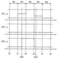
도 15에서, 그래프 g61은 행 방향으로 인접한 픽셀 블록들(PBj, PBi, PBk)의 누적 블록 스트레스 값들을 나타내고, 그래프 g62는 열 방향으로 인접한 픽셀 블록들(PBq, PBi, PBr)의 누적 블록 스트레스 값들을 나타낸다. 도 15의 경우는 행 방향으로 증가형인 동시에 열 방향으로 감소형인 경우를 나타낸다. 다만 도 14를 참조하여 전술한 바와 같이, 행 방향의 절대 값 (|BSTk-BSTj|=BST4-BST1)이 열 방향의 절대 값(|BSTr-BSTq|=BST3-BST1)보다 큰 경우(S554: ROW)에 해당하므로, 행 방향에 대해서만 제1 누적 블록 스트레스 값(BSTi)을 보정할 수 있다. In FIG. 15, a graph g61 shows cumulative block stress values of pixel blocks PBj, PBi and PBk adjacent in the row direction, and a graph g62 shows cumulative block stresses of pixel blocks PBq, PBi, Values. 15 shows the case of increasing type in the row direction and decreasing type in the column direction. If the absolute value (| BSTk-BSTj | = BST4-BST1) in the row direction is larger than the absolute value (| BSTr-BSTq | = BST3-BST1) in the column direction as described above with reference to Fig. 14 (S554: ROW), the first cumulative block stress value BSTi can be corrected only in the row direction.
다시 말해, 도 16에 도시된 바와 같이, 스트레스 보정부(260)는 제1 픽셀 블록(PBi)에 포함된 픽셀들 중에서 행 방향 스트레스 경계 위치(RSTBi)의 왼쪽에 위치한 픽셀들에 대하여 제2 픽셀 블록(PBj)의 누적 블록 스트레스 값(BST1)을 보정 스트레스 값(CSTi)으로서 제공하고, 제1 픽셀 블록(PBi)에 포함된 픽셀들 중에서 행 방향 스트레스 경계 위치(RSTBi)의 오른쪽에 위치한 픽셀들에 대하여 제3 픽셀 블록(PBk)의 누적 블록 스트레스 값(BST4)을 보정 스트레스 값(CSTi)으로서 제공할 수 있다.In other words, as shown in FIG. 16, the
도 17은 누적 블록 스트레스 값들이 열 방향으로 증가형인 경우를 나타내는 도면이고, 도 18은 누적 블록 스트레스 값을 열 방향으로 보정한 경우의 보정 스트레스 값을 나타내는 도면이다.FIG. 17 is a view showing a case where cumulative block stress values are incremental in a column direction, and FIG. 18 is a diagram showing correction stress values when a cumulative block stress value is corrected in a column direction.
도 17에서, 그래프 g71은 행 방향으로 인접한 픽셀 블록들(PBj, PBi, PBk)의 누적 블록 스트레스 값들을 나타내고, 그래프 g72는 열 방향으로 인접한 픽셀 블록들(PBq, PBi, PBr)의 누적 블록 스트레스 값들을 나타낸다. 도 17의 경우는 행 방향으로 증가형인 동시에 열 방향으로 증가형인 경우를 나타낸다. 다만 도 14를 참조하여 전술한 바와 같이, 열 방향의 절대 값(|BSTr-BSTq|=BST4-BST1)이 행 방향의 절대 값 (|BSTk-BSTj|=BST4-BST1) 보다 큰 경우(S554: COLUMN)에 해당하므로, 열 방향에 대해서만 제1 누적 블록 스트레스 값(BSTi)을 보정할 수 있다. 17, a graph g71 shows cumulative block stress values of pixel blocks PBj, PBi, and PBk adjacent in the row direction, and a graph g72 shows cumulative block stresses of pixel blocks PBq, PBi, Values. The case of Fig. 17 shows a case of increasing type in the row direction and increasing type in the column direction. If the absolute value (| BSTr-BSTq | = BST4-BST1) in the column direction is larger than the absolute value (| BSTk-BSTj | = BST4-BST1) in the row direction as described above with reference to Fig. 14 (S554: COLUMN), it is possible to correct the first cumulative block stress value BSTi only in the column direction.
다시 말해, 도 18에 도시된 바와 같이, 스트레스 보정부(260)는 제1 픽셀 블록(PBi)에 포함된 픽셀들 중에서 열 방향 스트레스 경계 위치(CSTBi)의 위쪽에 위치한 픽셀들에 대하여 제4 픽셀 블록(PBq)의 누적 블록 스트레스 값(BST1)을 보정 스트레스 값(CSTi)으로서 제공하고, 제1 픽셀 블록(PBi)에 포함된 픽셀들 중에서 열 방향 스트레스 경계 위치(CSTBi)의 아래쪽에 위치한 픽셀들에 대하여 제5 픽셀 블록(PBr)의 누적 블록 스트레스 값(BST4)을 보정 스트레스 값(CSTi)으로서 제공할 수 있다.In other words, as shown in FIG. 18, the
도 19는 누적 블록 스트레스 값을 행 방향 및 열 방향으로 보정한 경우의 보정 스트레스 값을 나타내는 도면이다.19 is a diagram showing the correction stress value when the accumulated block stress value is corrected in the row direction and the column direction.
도 19를 참조하면, 누적 블록 스트레스 값들(BSTi, BSTj, BSTk, BSTq, BSTr)이 행 방향으로도 증가형 또는 감소형이고 열 방향으로도 증가형 또는 감소형인 경우에, 전술한 방법에 의해 제1 픽셀 블록(PBi)의 내부의 행 방향 스트레스 경계 위치(RSTBi) 및 열 방향 스트레스 경계 위치(CSTBi)가 각각 추정될 수 있다. 19, when the cumulative block stress values (BSTi, BSTj, BSTk, BSTq, and BSTr) are both increasing or decreasing in the row direction and increasing or decreasing in the column direction, The row direction stress boundary position (RSTBi) and the column direction stress boundary position (CSTBi) inside one pixel block PBi can be respectively estimated.
이 경우, 도 19에 도시된 바와 같이, 행 방향 스트레스 경계 위치(RSTBi) 및 열 방향 스트레스 경계 위치(CSTBi)를 기준으로 제1 픽셀 블록(PBi)이 4개의 영역들로 분할될 수 있고, 상기 4개의 영역들은 각각의 보정 스트레스 값들(BSTa, BSTb, BSTc, BSTd)을 가질 수 있다. In this case, as shown in FIG. 19, the first pixel block PBi may be divided into four regions based on the row direction stress boundary position RSTBi and the column direction stress boundary position CSTBi, The four regions may have respective correction stress values (BSTa, BSTb, BSTc, BSTd).
예를 들어, 좌상 영역의 보정 스트레스 값(BSTa)은 제2 누적 블록 스트레스 값(BSTj)과 제4 누적 블록 스트레스 값(BSTq)의 평균 값{(BSTj+BSTq)/2}으로 결정될 수 있고, 우상 영역의 보정 스트레스 값(BSTb)은 제3 누적 블록 스트레스 값(BSTk)과 제4 누적 블록 스트레스 값(BSTq)의 평균 값{(BSTk+BSTq)/2}으로 결정될 수 있고, 좌하 영역의 보정 스트레스 값(BSTc)은 제2 누적 블록 스트레스 값(BSTj)과 제5 누적 블록 스트레스 값(BSTr)의 평균 값{(BSTj+BSTr)/2}으로 결정될 수 있고, 우하 영역의 보정 스트레스 값(BSTd)은 제3 누적 블록 스트레스 값(BSTk)과 제5 누적 블록 스트레스 값(BSTr)의 평균 값{(BSTk+BSTr)/2}으로 결정될 수 있다.For example, the correction stress value BSTa of the upper left region may be determined as an average value {(BSTj + BSTq) / 2} of the second cumulative block stress value BSTj and the fourth cumulative block stress value BSTq, The correction stress value BSTb of the upper right region can be determined by the average value {(BSTk + BSTq) / 2} of the third cumulative block stress value BSTk and the fourth cumulative block stress value BSTq, The stress value BSTc can be determined by the average value {(BSTj + BSTr) / 2} of the second cumulative block stress value BSTj and the fifth cumulative block stress value BSTr and the correction stress value BSTd ) Can be determined by the average value of the third cumulative block stress value BSTk and the fifth cumulative block stress value BSTr {(BSTk + BSTr) / 2}.
도 20은 본 발명의 실시예들에 따른 전자 기기를 나타내는 블록도이다.20 is a block diagram showing an electronic apparatus according to embodiments of the present invention.
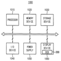
도 20을 참조하면, 전자 기기(1000)는 프로세서(1010), 메모리 장치(1020), 저장 장치(1030), 입출력 장치(1040), 파워 서플라이(1050) 및 디스플레이 장치(1060)를 포함할 수 있다. 전자 기기(1000)는 비디오 카드, 사운드 카드, 메모리 카드, USB 장치 등과 통신하거나, 또는 다른 시스템들과 통신할 수 있는 여러 포트(port)들을 더 포함할 수 있다.20, an
프로세서(1010)는 특정 계산들 또는 태스크(task)들을 수행할 수 있다. 실시예에 따라, 프로세서(1010)는 마이크로프로세서(micro processor), 중앙 처리 장치(CPU) 등일 수 있다. 프로세서(1010)는 어드레스 버스(address bus), 제어 버스(control bus) 및 데이터 버스(data bus) 등을 통하여 다른 구성 요소들에 연결될 수 있다. 실시예에 따라, 프로세서(1010)는 주변 구성요소 상호연결(Peripheral Component Interconnect; PCI) 버스와 같은 확장 버스에도 연결될 수 있다. 메모리 장치(1020)는 전자 기기(1000)의 동작에 필요한 데이터들을 저장할 수 있다. 예를 들어, 메모리 장치(1020)는 EPROM(Erasable Programmable Read-Only Memory), EEPROM(Electrically Erasable Programmable Read-Only Memory), 플래시 메모리(Flash Memory), PRAM(Phase Change Random Access Memory), RRAM(Resistance Random Access Memory), NFGM(Nano Floating Gate Memory), PoRAM(Polymer Random Access Memory), MRAM(Magnetic Random Access Memory), FRAM(Ferroelectric Random Access Memory) 등과 같은 비휘발성 메모리 장치 및/또는 DRAM(Dynamic Random Access Memory), SRAM(Static Random Access Memory), 모바일 DRAM 등과 같은 휘발성 메모리 장치를 포함할 수 있다. 저장 장치(1030)는 솔리드 스테이트 드라이브(Solid State Drive; SSD), 하드 디스크 드라이브(Hard Disk Drive; HDD), 씨디롬(CD-ROM) 등을 포함할 수 있다.
입출력 장치(1040)는 키보드, 키패드, 터치패드, 터치스크린, 마우스, 리모트 컨트롤러 등과 같은 입력 수단, 및 스피커, 프린터 등과 같은 출력 수단을 포함할 수 있다. 실시예에 따라, 디스플레이 장치(1060)는 입출력 장치(1040) 내에 구비될 수도 있다. 파워 서플라이(1050)는 전자 기기(1000)의 동작에 필요한 파워를 공급할 수 있다. 입체 영상 디스플레이 시스템(1060)은 상기 버스들 또는 다른 통신 링크를 통해서 다른 구성 요소들에 연결될 수 있다. The input /
전술한 바와 같이, 디스플레이 장치(1060)는 열화 보상부(DCB)(200)를 포함할 수 있다. 열화 보상부(200)는 픽셀들을 복수의 행들 및 복수의 열들로 이루어진 복수의 픽셀 블록들로 그룹화하고, 입력 영상 데이터에 기초하여 상기 픽셀 블록들에 포함되는 픽셀들의 열화된 정도를 각각 나타내는 누적 블록 스트레스 값들을 제공한다. 열화 보상부(200)는 서로 인접한 픽셀 블록들에 대한 상기 누적 블록 스트레스 값들에 기초하여 상기 누적 블록 스트레스 값들을 보정하여 보정 스트레스 값들을 제공하고, 상기 보정 스트레스 값들에 기초하여 상기 입력 영상 데이터를 보정한다. As described above, the
실시예에 따라, 전자 기기(1000)는 디지털 TV(Digital Television), 3D TV, 개인용 컴퓨터(Personal Computer; PC), 가정용 전자기기, 노트북 컴퓨터(Laptop Computer), 태블릿 컴퓨터(Table Computer), 휴대폰(Mobile Phone), 스마트 폰(Smart Phone), 개인 정보 단말기(personal digital assistant; PDA), 휴대형 멀티미디어 플레이어(portable multimedia player; PMP), 디지털 카메라(Digital Camera), 음악 재생기(Music Player), 휴대용 게임 콘솔(portable game console), 내비게이션(Navigation) 등과 같은 디스플레이 장치를 포함하는 임의의 전자 기기일 수 있다.According to an embodiment, the
도 21은 본 발명의 실시예들에 따른 휴대용 단말기를 나타내는 블록도이다.21 is a block diagram illustrating a portable terminal according to embodiments of the present invention.
도 21을 참조하면, 휴대용 단말기(1000)는 이미지 처리부(1100), 무선 송수신부(1200), 오디오 처리부(1300), 이미지 파일 생성부(1400), 메모리 장치(1500), 유저 인터페이스(1600), 애플리케이션 프로세서(1700) 및 전력 관리 장치(1800)를 포함한다.21, the
이미지 처리부(1100)는 렌즈(1110), 이미지 센서(1120), 이미지 프로세서(1130) 및 디스플레이 모듈(1140)을 포함한다. 무선 송수신부(1200)는 안테나(1210), 트랜시버(1220) 및 모뎀(1230)을 포함한다. 오디오 처리부(1300)는 오디오 프로세서(1310), 마이크(1320) 및 스피커(1330)를 포함한다. The
본 발명의 실시예들에 따라서, 디스플레이 모듈(1140)은 전술한 바와 같은 열화 보상부(미도시)를 포함할 수 있다. 상기 열화 보상부는 픽셀들을 복수의 행들 및 복수의 열들로 이루어진 복수의 픽셀 블록들로 그룹화하고, 입력 영상 데이터에 기초하여 상기 픽셀 블록들에 포함되는 픽셀들의 열화된 정도를 각각 나타내는 누적 블록 스트레스 값들을 제공한다. 상기 열화 보상부는 서로 인접한 픽셀 블록들에 대한 상기 누적 블록 스트레스 값들에 기초하여 상기 누적 블록 스트레스 값들을 보정하여 보정 스트레스 값들을 제공하고, 상기 보정 스트레스 값들에 기초하여 상기 입력 영상 데이터를 보정한다. According to embodiments of the present invention, the
휴대용 단말기(1000)에는 다양한 종류의 반도체 장치들이 포함될 수 있으며, 특히 애플리케이션 프로세서(1700)의 저전력, 고성능이 요구될 수 있다. 이러한 요구에 따라 애플리케이션 프로세서(1700)는 미세화 공정에 따라 멀티 코어 형태로 제공되기도 한다. 애플리케이션 프로세서(1700)는 중앙 처리 유닛(1702) 및 전력 관리 시스템(1704)을 포함할 수 있다. Various types of semiconductor devices may be included in the
전력 관리 장치(780)는 이미지 처리부(1100), 무선 송수신부(1200), 오디오 처리부(1300), 이미지 파일 생성부(1400), 메모리 장치(1500), 유저 인터페이스(1600), 애플리케이션 프로세서(1700)에 각각 구동 전압을 제공할 수 있다.The power management apparatus 780 includes an
전술한 바와 같이, 본 발명의 실시예들에 따른 전계발광 디스플레이 장치 및 그 구동 방법은, 픽셀들의 그룹화를 통하여 누적 스트레스 값의 데이터 용량을 감소하여 열화 보정 동작을 위한 메모리 용량과 대역폭을 감소함으로써 효율적으로 픽셀들의 열화를 보상할 수 있다. 또한 본 발명의 실시예들에 따른 전계발광 디스플레이 장치 및 그 구동 방법은, 픽셀 블록 내의 스트레스 경계 위치를 추정하고 이에 기초하여 누적 블록 스트레스 값들을 보정함으로써 더욱 효율적으로 픽셀들의 열화를 보상할 수 있다.As described above, the electroluminescent display device and the driving method thereof according to the embodiments of the present invention reduce the data capacity of the cumulative stress value through grouping of pixels, thereby reducing the memory capacity and bandwidth for the deterioration correcting operation, To compensate for the deterioration of the pixels. Further, the electroluminescent display device and the driving method thereof according to the embodiments of the present invention can more effectively compensate the deterioration of pixels by estimating the stress boundary position in the pixel block and correcting the accumulated block stress values based thereon.
본 발명의 실시예들에 따른 전계발광 디스플레이 장치 및 그 구동 방법은, 픽셀들의 열화를 보상하고 디스플레이 품질을 향상하기 위하여 유용하게 이용될 수 있다. 특히 고속으로 동작하고 전력 감소가 요구되는 메모리 카드, 솔리드 스테이트 드라이브(Solid State Drive; SSD), 컴퓨터(computer), 노트북(laptop), 핸드폰(cellular), 스마트폰(smart phone), MP3 플레이어, 피디에이(Personal Digital Assistants; PDA), 피엠피(Portable Multimedia Player; PMP), 디지털 TV, 디지털 카메라, 포터블 게임 콘솔(portable game console) 등과 같은 전자 기기에 더욱 유용하게 적용될 수 있다.An electroluminescent display device and a driving method thereof according to embodiments of the present invention can be usefully used to compensate for deterioration of pixels and improve display quality. (SSD), a computer, a laptop, a cellular phone, a smart phone, an MP3 player, a PDA, and the like, which operate at high speed and require power reduction. (PDAs), portable multimedia players (PMPs), digital TVs, digital cameras, portable game consoles, and the like.
이상에서는 본 발명의 실시예들을 참조하여 설명하였지만, 해당 기술 분야의 숙련된 당업자는 하기의 특허 청구의 범위에 기재된 본 발명의 사상 및 영역으로부터 벗어나지 않는 범위 내에서 본 발명을 다양하게 수정 및 변경시킬 수 있음을 이해할 수 있을 것이다.It will be apparent to those skilled in the art that various modifications and variations can be made in the present invention without departing from the spirit or scope of the invention as defined in the following claims. It can be understood that it is possible.
DCB, 200: 열화 보상부
SAM, 210: 샘플링부 누적부
ACC, 220: 누적부
MEM, 230: 메모리
EXT, 240: 추출부
BEST, 250: 경계 추정부
SCOR, 260: 스트레스 보정부
DCOR, 270: 데이터 보정부DCB, 200: deterioration compensator
SAM, 210: Sampling unit accumulation unit
ACC, 220: Cumulative unit
MEM, 230: memory
EXT, 240: Extraction section
BEST, 250: boundary estimating unit
SCOR, 260: Stress Correction
DCOR, 270: data correction unit
Claims (20)
입력 영상 데이터에 기초하여 상기 픽셀 블록들에 포함되는 픽셀들의 열화된 정도를 각각 나타내는 누적 블록 스트레스 값들을 제공하는 단계;
서로 인접한 픽셀 블록들에 대한 상기 누적 블록 스트레스 값들에 기초하여 상기 누적 블록 스트레스 값들을 보정하여 보정 스트레스 값들을 제공하는 단계; 및
상기 보정 스트레스 값들에 기초하여 상기 입력 영상 데이터를 보정하는 단계를 포함하는 전계발광 디스플레이 장치의 구동 방법.Grouping a plurality of pixels included in a display panel into a plurality of pixel blocks, the plurality of pixels being comprised of a plurality of rows and a plurality of columns;
Providing cumulative block stress values each indicative of a degree of deterioration of pixels included in the pixel blocks based on input image data;
Correcting the accumulated block stress values based on the accumulated block stress values for adjacent pixel blocks to provide correction stress values; And
And correcting the input image data based on the correction stress values.
서로 인접한 픽셀 블록들에 대한 상기 누적 블록 스트레스 값들에 기초하여 상기 픽셀 블록들의 내부의 스트레스 경계 위치를 추정하는 단계; 및
상기 스트레스 경계 위치에 기초하여 상기 누적 블록 스트레스 값들을 보정하여 상기 보정 스트레스 값들을 제공하는 단계를 포함하는 것을 특징으로 하는 전계발광 디스플레이 장치의 구동 방법.2. The method of claim 1, wherein providing the correction stress values comprises:
Estimating a stress boundary position within the pixel blocks based on the accumulated block stress values for adjacent pixel blocks; And
And correcting the accumulated block stress values based on the stress boundary position to provide the correction stress values.
상기 스트레스 경계 위치 부근의 픽셀들에 대한 상기 보정 스트레스 값들이 점진적으로 변화되도록 필터링을 수행하는 단계를 더 포함하는 것을 특징으로 하는 전계발광 디스플레이 장치의 구동 방법.3. The method of claim 2, wherein providing the correction stress values comprises:
Further comprising performing filtering such that the correction stress values for the pixels in the vicinity of the stress boundary position are gradually changed.
각 프레임의 상기 입력 영상 데이터에 기초하여 상기 픽셀 블록들에 각각 포함되는 픽셀들의 계조 값들의 블록 평균 값들을 계산하는 단계; 및
복수의 프레임들에 대하여 상기 블록 평균 값들을 누적하여 상기 누적 블록 스트레스 값들을 저장하는 단계를 포함하는 것을 특징으로 하는 전계발광 디스플레이 장치의 구동 방법.2. The method of claim 1, wherein providing the cumulative block stress values comprises:
Calculating block average values of tone values of pixels included in each of the pixel blocks based on the input image data of each frame; And
And storing the accumulated block stress values by accumulating the block average values for a plurality of frames.
제1 픽셀 블록의 제1 누적 블록 스트레스 값, 상기 제1 픽셀 블록의 왼쪽에 인접한 제2 픽셀 블록의 제2 누적 블록 스트레스 값 및 상기 제1 픽셀 블록의 오른쪽에 인접한 제3 픽셀 블록의 제3 누적 블록 스트레스 값에 기초하여 상기 제1 픽셀 블록의 보정 스트레스 값을 제공하는 단계를 포함하는 것을 특징으로 하는 전계발광 디스플레이 장치의 구동 방법.2. The method of claim 1, wherein providing the correction stress values comprises:
The first cumulative block stress value of the first pixel block, the second cumulative block stress value of the second pixel block adjacent to the left of the first pixel block, and the third cumulative block stress value of the third pixel block adjacent to the right side of the first pixel block, And providing the correction stress value of the first pixel block based on the block stress value.
상기 제1 누적 블록 스트레스 값, 상기 제2 누적 블록 스트레스 값 및 상기 제3 누적 블록 스트레스 값의 차이 값들을 적어도 하나의 기준 값과 비교하여 상기 누적 블록 스트레스 값들이 증가형 또는 감소형인지 판단하는 단계;
상기 누적 블록 스트레스 값들이 증가형 또는 감소형이라고 판단된 경우, 상기 차이 값들에 기초하여 상기 제1 픽셀 블록의 내부의 스트레스 경계 위치를 추정하는 단계; 및
상기 스트레스 경계 위치에 기초하여 상기 제1 누적 블록 스트레스 값을 보정하여 상기 제1 픽셀 블록의 상기 보정 스트레스 값을 제공하는 단계를 포함하는 것을 특징으로 하는 전계발광 디스플레이 장치의 구동 방법.6. The method of claim 5, wherein providing the correction stress value of the first pixel block comprises:
Comparing the difference values of the first cumulative block stress value, the second cumulative block stress value, and the third cumulative block stress value with at least one reference value to determine whether the cumulative block stress values are incremental or decremental ;
Estimating a stress boundary position within the first pixel block based on the difference values when the accumulated block stress values are determined to be incremental or decremental; And
And correcting the first cumulative block stress value based on the stress boundary position to provide the correction stress value of the first pixel block.
상기 누적 블록 스트레스 값들이 증가형 또는 감소형이 아니라고 판단된 경우, 상기 제1 누적 블록 스트레스 값을 그대로 상기 제1 픽셀 블록의 상기 보정 스트레스 값으로서 제공하는 단계를 더 포함하는 것을 특징으로 하는 전계발광 디스플레이 장치의 구동 방법.7. The method of claim 6, wherein providing the correction stress value of the first pixel block comprises:
Further comprising the step of providing the first cumulative block stress value as the correction stress value of the first pixel block when it is determined that the cumulative block stress values are not incremental or decremental, A method of driving a display device.
상기 제3 누적 블록 스트레스 값에서 상기 제1 누적 블록 스트레스 값을 뺀 제1 차이 값을 계산하는 단계;
상기 제1 누적 블록 스트레스 값에서 상기 제2 누적 블록 스트레스 값을 뺀 제2 차이 값을 계산하는 단계;
상기 제1 차이 값이 양의 기준 값보다 크고 상기 제2 차이 값이 상기 양의 기준 값보다 큰 경우 상기 누적 블록 스트레스 값들이 증가형이라고 판단하는 단계; 및
상기 제1 차이 값이 음의 기준 값보다 작고 상기 제2 차이 값이 상기 음의 기준 값보다 작은 경우 상기 누적 블록 스트레스 값들이 감소형이라고 판단하는 단계를 포함하는 것을 특징으로 하는 전계발광 디스플레이 장치의 구동 방법.7. The method of claim 6, wherein determining whether the cumulative block stress values are incremental or decremental comprises:
Calculating a first difference value by subtracting the first cumulative block stress value from the third cumulative block stress value;
Calculating a second difference value by subtracting the second cumulative block stress value from the first cumulative block stress value;
Determining that the accumulated block stress values are incremental if the first difference value is greater than a positive reference value and the second difference value is greater than the positive reference value; And
And determining that the accumulated block stress values are of the reduced type if the first difference value is smaller than the negative reference value and the second difference value is smaller than the negative reference value. Driving method.
상기 제3 누적 블록 스트레스 값에서 상기 제2 누적 블록 스트레스 값을 뺀 제3 차이 값을 계산하는 단계;
상기 제1 차이 값을 상기 제3 차이 값으로 나눈 비례 값을 계산하는 단계; 및
상기 비례 값에 기초하여 상기 스트레스 경계 위치를 계산하는 단계를 포함하는 것을 특징으로 하는 전계발광 디스플레이 장치의 구동 방법.9. The method of claim 8, wherein estimating a stress boundary location within the first pixel block comprises:
Calculating a third difference value by subtracting the second cumulative block stress value from the third cumulative block stress value;
Calculating a proportional value obtained by dividing the first difference value by the third difference value; And
And calculating the stress boundary position based on the proportional value.
상기 제1 픽셀 블록에 포함된 픽셀들 중에서 상기 스트레스 경계 위치의 왼쪽에 위치한 픽셀들에 대하여 상기 제2 누적 블록 스트레스 값을 상기 보정 스트레스 값으로서 제공하는 단계; 및
상기 제1 픽셀 블록에 포함된 픽셀들 중에서 상기 스트레스 경계 위치의 오른쪽에 위치한 픽셀들에 대하여 상기 제3 누적 블록 스트레스 값을 상기 보정 스트레스 값으로서 제공하는 단계를 포함하는 것을 특징으로 하는 전계발광 디스플레이 장치의 구동 방법.10. The method of claim 9, wherein the step of correcting the first cumulative block stress value based on the stress boundary position to provide the correction stress value of the first pixel block comprises:
Providing the second cumulative block stress value as the correction stress value for pixels located to the left of the stress boundary position among the pixels included in the first pixel block; And
And providing the third accumulated block stress value as the correction stress value to pixels located to the right of the stress boundary position among the pixels included in the first pixel block. .
상기 스트레스 경계 위치 부근의 픽셀들에 대하여 상기 보정 스트레스 값들이 점진적으로 변화되도록 필터링을 수행하는 단계를 더 포함하는 것을 특징으로 하는 전계발광 디스플레이 장치의 구동 방법.The method of claim 10, wherein the step of correcting the first accumulated block stress value based on the stress boundary position to provide the correction stress value of the first pixel block comprises:
Further comprising the step of performing filtering such that the correction stress values are gradually changed with respect to pixels near the stress boundary position.
제1 픽셀 블록의 제1 누적 블록 스트레스 값, 상기 제1 픽셀 블록의 왼쪽에 인접한 제2 픽셀 블록의 제2 누적 블록 스트레스 값, 상기 제1 픽셀 블록의 오른쪽에 인접한 제3 픽셀 블록의 제3 누적 블록 스트레스 값, 상기 제1 픽셀 블록의 위쪽에 인접한 제4 픽셀 블록의 제4 누적 블록 스트레스 값 및 상기 제1 픽셀 블록의 아래쪽에 인접한 제5 픽셀 블록의 제5 누적 블록 스트레스 값에 기초하여 상기 제1 픽셀 블록의 보정 스트레스 값을 제공하는 단계를 포함하는 것을 특징으로 하는 전계발광 디스플레이 장치의 구동 방법.2. The method of claim 1, wherein providing the correction stress values comprises:
The first cumulative block stress value of the first pixel block, the second cumulative block stress value of the second pixel block adjacent to the left of the first pixel block, the third cumulative block stress value of the third pixel block adjacent to the right side of the first pixel block, Based on the block stress value, the fourth cumulative block stress value of the fourth pixel block adjacent to the upper side of the first pixel block, and the fifth cumulative block stress value of the fifth pixel block adjacent to the lower side of the first pixel block, And providing a correction stress value of one pixel block.
상기 제1 누적 블록 스트레스 값, 상기 제2 누적 블록 스트레스 값 및 상기 제3 누적 블록 스트레스 값의 행 방향 차이 값들을 적어도 하나의 기준 값과 비교하여 상기 누적 블록 스트레스 값들이 행 방향으로 증가형 또는 감소형인지 판단하는 단계;
상기 제1 누적 블록 스트레스 값, 상기 제4 누적 블록 스트레스 값 및 상기 제5 누적 블록 스트레스 값의 열 방향 차이 값들을 상기 적어도 하나의 기준 값과 비교하여 상기 누적 블록 스트레스 값들이 열 방향으로 증가형 또는 감소형인지 판단하는 단계;
상기 누적 블록 스트레스 값들이 행 방향 또는 열 방향으로 증가형 또는 감소형이라고 판단된 경우, 상기 행 방향 차이 값들 또는 상기 열 방향 차이 값들에 기초하여 상기 제1 픽셀 블록의 내부의 스트레스 경계 위치를 추정하는 단계; 및
상기 스트레스 경계 위치에 기초하여 상기 제1 누적 블록 스트레스 값을 보정하여 상기 제1 픽셀 블록의 상기 보정 스트레스 값을 제공하는 단계를 포함하는 것을 특징으로 하는 전계발광 디스플레이 장치의 구동 방법.13. The method of claim 12, wherein providing the correction stress value of the first pixel block comprises:
And comparing the row direction difference values of the first cumulative block stress value, the second cumulative block stress value, and the third cumulative block stress value with at least one reference value so that the cumulative block stress values are increased or decreased in the row direction Judging whether the pattern is a pattern;
Comparing the column direction difference values of the first cumulative block stress value, the fourth cumulative block stress value, and the fifth cumulative block stress value with the at least one reference value so that the cumulative block stress values are increased or decreased in the column direction, Deciding whether the type is reduction type;
Estimating a stress boundary position inside the first pixel block based on the row direction difference values or the column direction difference values when it is determined that the accumulated block stress values are incremental or decremental in a row direction or a column direction step; And
And correcting the first cumulative block stress value based on the stress boundary position to provide the correction stress value of the first pixel block.
상기 제3 누적 블록 스트레스 값에서 상기 제1 누적 블록 스트레스 값을 뺀 제1 행 방향 차이 값을 계산하는 단계;
상기 제1 누적 블록 스트레스 값에서 상기 제2 누적 블록 스트레스 값을 뺀 제2 행 방향 차이 값을 계산하는 단계;
상기 제1 행 방향 차이 값이 양의 기준 값보다 크고 상기 제2 행 방향 차이 값이 상기 양의 기준 값보다 큰 경우 상기 누적 블록 스트레스 값들이 행 방향으로 증가형이라고 판단하는 단계; 및
상기 제1 행 방향 차이 값이 음의 기준 값보다 작고 상기 제2 행 방향 차이 값이 상기 음의 기준 값보다 작은 경우 상기 누적 블록 스트레스 값들이 행 방향으로 감소형이라고 판단하는 단계를 포함하는 것을 특징으로 하는 전계발광 디스플레이 장치의 구동 방법.14. The method of claim 13, wherein determining whether the cumulative block stress values are incremental or decremental in the row direction comprises:
Calculating a first row direction difference value by subtracting the first cumulative block stress value from the third cumulative block stress value;
Calculating a second row direction difference value by subtracting the second cumulative block stress value from the first cumulative block stress value;
Determining that the cumulative block stress values are incremental in a row direction if the first row direction difference value is greater than a positive reference value and the second row direction difference value is greater than the positive reference value; And
And determining that the accumulated block stress values are decremented in the row direction when the first row direction difference value is smaller than the negative reference value and the second row direction difference value is smaller than the negative reference value And a driving method of the electroluminescence display device.
상기 제5 누적 블록 스트레스 값에서 상기 제1 누적 블록 스트레스 값을 뺀 제1 열 방향 차이 값을 계산하는 단계;
상기 제1 누적 블록 스트레스 값에서 상기 제4 누적 블록 스트레스 값을 뺀 제2 열 방향 차이 값을 계산하는 단계;
상기 제1 열 방향 차이 값이 상기 양의 기준 값보다 크고 상기 제2 열 방향 차이 값이 상기 양의 기준 값보다 큰 경우 상기 누적 블록 스트레스 값들이 열 방향으로 증가형이라고 판단하는 단계; 및
상기 제1 열 방향 차이 값이 상기 음의 기준 값보다 작고 상기 제2 열 방향 차이 값이 상기 음의 기준 값보다 작은 경우 상기 누적 블록 스트레스 값들이 열 방향으로 감소형이라고 판단하는 단계를 포함하는 것을 특징으로 하는 전계발광 디스플레이 장치의 구동 방법.15. The method of claim 14, wherein determining whether the cumulative block stress values are incremental or decremental in the column direction comprises:
Calculating a first column difference value by subtracting the first cumulative block stress value from the fifth cumulative block stress value;
Calculating a second column difference value by subtracting the fourth cumulative block stress value from the first cumulative block stress value;
Determining that the cumulative block stress values are incremental in the column direction if the first column difference value is greater than the positive reference value and the second column difference value is greater than the positive reference value; And
And determining that the cumulative block stress values are decremental in the column direction if the first column direction difference value is smaller than the negative reference value and the second column direction difference value is smaller than the negative reference value And a driving method of the electroluminescence display device.
상기 누적 블록 스트레스 값들이 행 방향으로 증가형 또는 감소형이라고 판단된 경우, 상기 제3 누적 블록 스트레스 값에서 상기 제2 누적 블록 스트레스 값을 뺀 제3 행 방향 차이 값을 계산하는 단계;
상기 제1 행 방향 차이 값을 상기 제3 행 방향 차이 값으로 나눈 행 방향 비례 값을 계산하는 단계; 및
상기 행 방향 비례 값에 기초하여 행 방향 스트레스 경계 위치를 계산하는 단계를 포함하는 것을 특징으로 하는 전계발광 디스플레이 장치의 구동 방법.16. The method of claim 15, wherein estimating a stress boundary location within the first pixel block comprises:
Calculating a third row direction difference value obtained by subtracting the second cumulative block stress value from the third cumulative block stress value when the cumulative block stress values are determined to be an increasing type or a decreasing type in a row direction;
Calculating a row direction proportional value in which the first row direction difference value is divided by the third row direction difference value; And
And calculating a row direction stress boundary position based on the row direction proportional value.
상기 누적 블록 스트레스 값들이 열 방향으로 증가형 또는 감소형이라고 판단된 경우, 상기 제5 누적 블록 스트레스 값에서 상기 제4 누적 블록 스트레스 값을 뺀 제3 열 방향 차이 값을 계산하는 단계;
상기 제1 열 방향 차이 값을 상기 제3 열 방향 차이 값으로 나눈 열 방향 비례 값을 계산하는 단계; 및
상기 열 방향 비례 값에 기초하여 열 방향 스트레스 경계 위치를 계산하는 단계를 더 포함하는 것을 특징으로 하는 전계발광 디스플레이 장치의 구동 방법.17. The method of claim 16, wherein estimating a stress boundary location within the first pixel block comprises:
Calculating a third column difference value by subtracting the fourth accumulation block stress value from the fifth accumulation block stress value when it is determined that the accumulated block stress values are incremented or decremented in the column direction;
Calculating a column direction proportional value obtained by dividing the first column direction difference value by the third column direction difference value; And
And calculating a column direction stress boundary position based on the column direction proportional value.
상기 누적 블록 스트레스 값들이 행 방향으로 증가형 또는 감소형이라고 판단되고 열 방향으로 증가형 또는 감소형이 아니라고 판단된 경우, 상기 제1 픽셀 블록에 포함된 픽셀들 중에서 상기 행 방향 스트레스 경계 위치의 왼쪽에 위치한 픽셀들에 대하여 상기 제2 누적 블록 스트레스 값을 상기 보정 스트레스 값으로서 제공하고 상기 제1 픽셀 블록에 포함된 픽셀들 중에서 상기 행 방향 스트레스 경계 위치의 오른쪽에 위치한 픽셀들에 대하여 상기 제3 누적 블록 스트레스 값을 상기 보정 스트레스 값으로서 제공하는 단계; 및
상기 누적 블록 스트레스 값들이 열 방향으로 증가형 또는 감소형이라고 판단되고 행 방향으로 증가형 또는 감소형이 아니라고 판단된 경우, 상기 제1 픽셀 블록에 포함된 픽셀들 중에서 상기 열 방향 스트레스 경계 위치의 위쪽에 위치한 픽셀들에 대하여 상기 제4 누적 블록 스트레스 값을 상기 보정 스트레스 값으로서 제공하고 상기 제1 픽셀 블록에 포함된 픽셀들 중에서 상기 열 방향 스트레스 경계 위치의 아래쪽에 위치한 픽셀들에 대하여 상기 제5 누적 블록 스트레스 값을 상기 보정 스트레스 값으로서 제공하는 단계를 포함하는 것을 특징으로 하는 전계발광 디스플레이 장치의 구동 방법.18. The method of claim 17, wherein the correcting the first cumulative block stress value based on the stress boundary position to provide the correction stress value of the first pixel block comprises:
Wherein when the cumulative block stress values are determined to be incremental or decremental in the row direction and are not incremental or decremental in the column direction, For the pixels located at the right side of the row direction stress boundary position among the pixels included in the first pixel block, and for the pixels located at the right side of the row direction stress boundary position among the pixels included in the first pixel block, Providing a block stress value as the correction stress value; And
Wherein when the cumulative block stress values are determined to be incremental or decremental in the column direction and are not incremental or decremental in the row direction, For the pixels located in the column direction of the column direction, the fourth cumulative block stress value as the correction stress value for the pixels located in the column direction, and for the pixels located below the column direction stress boundary position among the pixels included in the first pixel block, And providing the block stress value as the correction stress value.
상기 누적 블록 스트레스 값들이 행 방향으로도 증가형 또는 감소형이라고 판단되고 열 방향으로도 증가형 또는 감소형이라고 판단된 경우, 상기 제3 누적 블록 스트레스 값과 상기 제2 누적 블록 스트레스 값의 차이의 절대 값과 상기 제5 누적 블록 스트레스 값과 상기 제4 누적 블록 스트레스 값의 차이의 절대 값을 비교하여 행 방향 및 열 방향 중에서 하나의 방향에 대해서만 상기 제1 누적 블록 스트레스 값을 보정하여 상기 제1 픽셀 블록의 상기 보정 스트레스 값을 제공하는 것을 특징으로 하는 전계발광 디스플레이 장치의 구동 방법.14. The method of claim 13,
When the cumulative block stress values are determined to be incremental or decremental in the row direction and are determined to be incremental or decremental in the column direction, the difference between the third cumulative block stress value and the second cumulative block stress value The absolute value of the difference between the absolute value and the absolute value of the difference between the fifth accumulated block stress value and the fourth accumulated block stress value to correct the first accumulated block stress value only in one of the row direction and the column direction, And providing the correction stress value of the pixel block.
상기 픽셀들을 복수의 행들 및 복수의 열들로 이루어진 복수의 픽셀 블록들로 그룹화하고, 입력 영상 데이터에 기초하여 상기 픽셀 블록들에 포함되는 픽셀들의 열화된 정도를 각각 나타내는 누적 블록 스트레스 값들을 제공하고, 서로 인접한 픽셀 블록들에 대한 상기 누적 블록 스트레스 값들에 기초하여 상기 누적 블록 스트레스 값들을 보정하여 보정 스트레스 값들을 제공하고, 상기 보정 스트레스 값들에 기초하여 상기 입력 영상 데이터를 보정하는 열화 보상부; 및
상기 보정된 입력 영상 데이터에 기초하여 상기 픽셀들을 구동하는 데이터 드라이버를 포함하는 전계발광 디스플레이 장치.A display panel including a plurality of pixels;
Grouping the pixels into a plurality of pixel blocks each having a plurality of rows and a plurality of columns, providing cumulative block stress values each representing a deterioration degree of pixels included in the pixel blocks based on input image data, A degradation compensation unit that corrects the accumulated block stress values based on the accumulated block stress values for adjacent pixel blocks to provide correction stress values and corrects the input image data based on the correction stress values; And
And a data driver for driving the pixels based on the corrected input image data.
Priority Applications (2)
| Application Number | Priority Date | Filing Date | Title |
|---|---|---|---|
| KR1020140157528A KR102313733B1 (en) | 2014-11-13 | 2014-11-13 | Electroluminescent display device and method of driving the same to compensate for degeneration of pixels |
| US14/692,054 US9947265B2 (en) | 2014-11-13 | 2015-04-21 | Electroluminescent display device and method of driving the same to compensate for degeneration of pixels |
Applications Claiming Priority (1)
| Application Number | Priority Date | Filing Date | Title |
|---|---|---|---|
| KR1020140157528A KR102313733B1 (en) | 2014-11-13 | 2014-11-13 | Electroluminescent display device and method of driving the same to compensate for degeneration of pixels |
Publications (2)
| Publication Number | Publication Date |
|---|---|
| KR20160057504A true KR20160057504A (en) | 2016-05-24 |
| KR102313733B1 KR102313733B1 (en) | 2021-10-19 |
Family
ID=55962223
Family Applications (1)
| Application Number | Title | Priority Date | Filing Date |
|---|---|---|---|
| KR1020140157528A Active KR102313733B1 (en) | 2014-11-13 | 2014-11-13 | Electroluminescent display device and method of driving the same to compensate for degeneration of pixels |
Country Status (2)
| Country | Link |
|---|---|
| US (1) | US9947265B2 (en) |
| KR (1) | KR102313733B1 (en) |
Cited By (7)
| Publication number | Priority date | Publication date | Assignee | Title |
|---|---|---|---|---|
| US10885301B2 (en) | 2017-10-13 | 2021-01-05 | Samsung Electronics Co., Ltd. | Method for obtaining biometric information and electronic device thereof |
| KR20210091859A (en) * | 2020-01-14 | 2021-07-23 | 삼성디스플레이 주식회사 | Display device and method of compensating degradation of display device |
| JP2021140185A (en) * | 2017-06-07 | 2021-09-16 | 深▲セン▼通鋭微電子技術有限公司 | Display device and image data correction method |
| KR20220060219A (en) * | 2020-11-04 | 2022-05-11 | 삼성전자주식회사 | Method of compensating for degeneration of electroluminescent display device and display system performing the same |
| WO2022119112A1 (en) * | 2020-12-04 | 2022-06-09 | 삼성전자 주식회사 | Electronic device and method for predicting and compensating for burn-in of display |
| KR20220079368A (en) * | 2020-12-04 | 2022-06-13 | 삼성전자주식회사 | Electronic device and method for predicting burn-in of display and compensating for the burn-in of the display |
| US11967262B2 (en) | 2021-10-07 | 2024-04-23 | Samsung Display Co., Ltd. | Display device compensating for light stress |
Families Citing this family (14)
| Publication number | Priority date | Publication date | Assignee | Title |
|---|---|---|---|---|
| KR102287907B1 (en) * | 2015-06-22 | 2021-08-10 | 삼성디스플레이 주식회사 | Degradation compensator of organic light emitting diode display device |
| KR102591789B1 (en) * | 2018-01-02 | 2023-10-23 | 삼성디스플레이 주식회사 | Display device and electronic device having the same |
| WO2019234548A1 (en) * | 2018-06-06 | 2019-12-12 | 株式会社半導体エネルギー研究所 | Method for actuating display device |
| US11087673B2 (en) * | 2018-12-27 | 2021-08-10 | Novatek Microelectronics Corp. | Image apparatus and a method of preventing burn in |
| CN110751923B (en) * | 2019-11-28 | 2022-12-30 | 北京加益科技有限公司 | Hybrid aging compensation method and device, electronic equipment and readable storage medium |
| KR102666116B1 (en) * | 2019-12-30 | 2024-05-13 | 엘지디스플레이 주식회사 | Display device and method for controlling display device |
| KR102770261B1 (en) * | 2020-07-07 | 2025-02-20 | 삼성전자주식회사 | Display driver integrated circuit and display device including the same |
| WO2022145023A1 (en) * | 2020-12-29 | 2022-07-07 | シャープ株式会社 | Display device and method for driving display device |
| KR102936741B1 (en) | 2021-05-26 | 2026-03-12 | 삼성디스플레이 주식회사 | Display apparatus and method of driving display panel using the same |
| KR102938291B1 (en) * | 2022-07-06 | 2026-03-12 | 주식회사 엘엑스세미콘 | Logo detection module, timing controller including the same and method for driving the same |
| KR20240065633A (en) | 2022-11-04 | 2024-05-14 | 삼성디스플레이 주식회사 | Control device to drive display panel, display device including the same, method of operating the same |
| CN118575213A (en) | 2022-11-25 | 2024-08-30 | 京东方科技集团股份有限公司 | Display device, control method, device, apparatus, and computer storage medium |
| CN120660132A (en) * | 2023-02-16 | 2025-09-16 | 高通股份有限公司 | Frame layer condition compensation for ambient light adaptive pixel aging |
| KR20250122569A (en) * | 2024-02-06 | 2025-08-14 | 삼성디스플레이 주식회사 | Display driver integrated circuit and display device including the same |
Citations (4)
| Publication number | Priority date | Publication date | Assignee | Title |
|---|---|---|---|---|
| KR20010094575A (en) * | 2000-03-31 | 2001-11-01 | 최명렬 | Multi gray level contrast control apparatus and method for displaying real time |
| KR20040064950A (en) * | 2003-01-11 | 2004-07-21 | (주)플렛디스 | Apparatus and Method for Improving Contrast and for removing moving afterimage in a Flat Panel Display |
| KR20140075040A (en) * | 2012-12-07 | 2014-06-19 | 엘지디스플레이 주식회사 | Organic light emitting display device and method for driving theteof |
| KR20140075061A (en) * | 2012-12-10 | 2014-06-19 | 엘지디스플레이 주식회사 | Organic Light Emitting Display And Compensation Method Of Degradation Thereof |
Family Cites Families (5)
| Publication number | Priority date | Publication date | Assignee | Title |
|---|---|---|---|---|
| JP2010169991A (en) | 2009-01-26 | 2010-08-05 | Hitachi Displays Ltd | Display device |
| CA2692097A1 (en) * | 2010-02-04 | 2011-08-04 | Ignis Innovation Inc. | Extracting correlation curves for light emitting device |
| US9881532B2 (en) * | 2010-02-04 | 2018-01-30 | Ignis Innovation Inc. | System and method for extracting correlation curves for an organic light emitting device |
| KR101865586B1 (en) * | 2011-04-08 | 2018-06-11 | 삼성디스플레이 주식회사 | Organic Light Emitting Display Device and Driving Method Thereof |
| KR102112325B1 (en) | 2014-01-08 | 2020-05-19 | 삼성디스플레이 주식회사 | Organic Light Emitting Display Device and Driving Method Thereof |
-
2014
- 2014-11-13 KR KR1020140157528A patent/KR102313733B1/en active Active
-
2015
- 2015-04-21 US US14/692,054 patent/US9947265B2/en active Active
Patent Citations (4)
| Publication number | Priority date | Publication date | Assignee | Title |
|---|---|---|---|---|
| KR20010094575A (en) * | 2000-03-31 | 2001-11-01 | 최명렬 | Multi gray level contrast control apparatus and method for displaying real time |
| KR20040064950A (en) * | 2003-01-11 | 2004-07-21 | (주)플렛디스 | Apparatus and Method for Improving Contrast and for removing moving afterimage in a Flat Panel Display |
| KR20140075040A (en) * | 2012-12-07 | 2014-06-19 | 엘지디스플레이 주식회사 | Organic light emitting display device and method for driving theteof |
| KR20140075061A (en) * | 2012-12-10 | 2014-06-19 | 엘지디스플레이 주식회사 | Organic Light Emitting Display And Compensation Method Of Degradation Thereof |
Cited By (8)
| Publication number | Priority date | Publication date | Assignee | Title |
|---|---|---|---|---|
| JP2021140185A (en) * | 2017-06-07 | 2021-09-16 | 深▲セン▼通鋭微電子技術有限公司 | Display device and image data correction method |
| US10885301B2 (en) | 2017-10-13 | 2021-01-05 | Samsung Electronics Co., Ltd. | Method for obtaining biometric information and electronic device thereof |
| KR20210091859A (en) * | 2020-01-14 | 2021-07-23 | 삼성디스플레이 주식회사 | Display device and method of compensating degradation of display device |
| KR20220060219A (en) * | 2020-11-04 | 2022-05-11 | 삼성전자주식회사 | Method of compensating for degeneration of electroluminescent display device and display system performing the same |
| WO2022119112A1 (en) * | 2020-12-04 | 2022-06-09 | 삼성전자 주식회사 | Electronic device and method for predicting and compensating for burn-in of display |
| KR20220079368A (en) * | 2020-12-04 | 2022-06-13 | 삼성전자주식회사 | Electronic device and method for predicting burn-in of display and compensating for the burn-in of the display |
| US11948484B2 (en) | 2020-12-04 | 2024-04-02 | Samsung Electronics Co., Ltd. | Electronic device and method for predicting and compensating for burn-in of display |
| US11967262B2 (en) | 2021-10-07 | 2024-04-23 | Samsung Display Co., Ltd. | Display device compensating for light stress |
Also Published As
| Publication number | Publication date |
|---|---|
| US20160140895A1 (en) | 2016-05-19 |
| KR102313733B1 (en) | 2021-10-19 |
| US9947265B2 (en) | 2018-04-17 |
Similar Documents
| Publication | Publication Date | Title |
|---|---|---|
| KR102313733B1 (en) | Electroluminescent display device and method of driving the same to compensate for degeneration of pixels | |
| KR102378190B1 (en) | Electroluminescent display device for reducing color distortion of low gray values and method of operating the same | |
| CN105741725B (en) | Display device and method for driving the display device | |
| CN103839515B (en) | Time schedule controller and driving method thereof and use its display device | |
| KR102735728B1 (en) | Electroluminescent display device and method of compensating luminance in the same | |
| US10971065B2 (en) | Display device, and method of determining a power supply voltage | |
| CN105741776B (en) | Organic light emitting diode display and method for sensing its characteristic | |
| KR101975215B1 (en) | Organic light emitting display device and method for driving thereof | |
| US9299283B2 (en) | Apparatus for compensating color characteristics in display device and compensating method thereof | |
| US20250349250A1 (en) | Method of compensating for degeneration of electroluminescent display device and display system performing the same | |
| US10672336B2 (en) | Organic light emitting display and method for driving the same | |
| KR20160059035A (en) | Electroluminescent display device, system including the same and method of driving the same | |
| KR20200004483A (en) | Organic light emitting display device and method of driving the same | |
| KR102770261B1 (en) | Display driver integrated circuit and display device including the same | |
| KR20180002948A (en) | Display device and methd for controlling peak luminance of the same | |
| EP3016094B1 (en) | Driving unit and display device | |
| KR20150034948A (en) | Organic light emitting display device and method of driving the same | |
| KR102106558B1 (en) | Organic light emitting display device and method for driving thereof | |
| US9478163B2 (en) | Organic light emitting diode display and method of driving the same | |
| KR20110123952A (en) | Organic light emitting display device and driving method thereof | |
| KR20170121378A (en) | Organic light emitting diode display device | |
| US20230252931A1 (en) | Display device | |
| KR102018752B1 (en) | Apparatus and Method for Adjusting Luminance, Organic Light Emitting Display Device | |
| KR102005760B1 (en) | Timing controller, driving method thereof, and display device using the same | |
| KR102294852B1 (en) | Organic light emitting display device and driving method thereof |
Legal Events
| Date | Code | Title | Description |
|---|---|---|---|
| PA0109 | Patent application |
St.27 status event code: A-0-1-A10-A12-nap-PA0109 |
|
| P11-X000 | Amendment of application requested |
St.27 status event code: A-2-2-P10-P11-nap-X000 |
|
| P13-X000 | Application amended |
St.27 status event code: A-2-2-P10-P13-nap-X000 |
|
| R15-X000 | Change to inventor requested |
St.27 status event code: A-3-3-R10-R15-oth-X000 |
|
| R16-X000 | Change to inventor recorded |
St.27 status event code: A-3-3-R10-R16-oth-X000 |
|
| R18-X000 | Changes to party contact information recorded |
St.27 status event code: A-3-3-R10-R18-oth-X000 |
|
| PG1501 | Laying open of application |
St.27 status event code: A-1-1-Q10-Q12-nap-PG1501 |
|
| R18-X000 | Changes to party contact information recorded |
St.27 status event code: A-3-3-R10-R18-oth-X000 |
|
| A201 | Request for examination | ||
| PA0201 | Request for examination |
St.27 status event code: A-1-2-D10-D11-exm-PA0201 |
|
| E902 | Notification of reason for refusal | ||
| PE0902 | Notice of grounds for rejection |
St.27 status event code: A-1-2-D10-D21-exm-PE0902 |
|
| AMND | Amendment | ||
| E13-X000 | Pre-grant limitation requested |
St.27 status event code: A-2-3-E10-E13-lim-X000 |
|
| P11-X000 | Amendment of application requested |
St.27 status event code: A-2-2-P10-P11-nap-X000 |
|
| P13-X000 | Application amended |
St.27 status event code: A-2-2-P10-P13-nap-X000 |
|
| E601 | Decision to refuse application | ||
| PE0601 | Decision on rejection of patent |
St.27 status event code: N-2-6-B10-B15-exm-PE0601 |
|
| X091 | Application refused [patent] | ||
| AMND | Amendment | ||
| E13-X000 | Pre-grant limitation requested |
St.27 status event code: A-2-3-E10-E13-lim-X000 |
|
| P11-X000 | Amendment of application requested |
St.27 status event code: A-2-2-P10-P11-nap-X000 |
|
| P13-X000 | Application amended |
St.27 status event code: A-2-2-P10-P13-nap-X000 |
|
| PX0901 | Re-examination |
St.27 status event code: A-2-3-E10-E12-rex-PX0901 |
|
| PX0701 | Decision of registration after re-examination |
St.27 status event code: A-3-4-F10-F13-rex-PX0701 |
|
| X701 | Decision to grant (after re-examination) | ||
| GRNT | Written decision to grant | ||
| PR0701 | Registration of establishment |
St.27 status event code: A-2-4-F10-F11-exm-PR0701 |
|
| PR1002 | Payment of registration fee |
St.27 status event code: A-2-2-U10-U11-oth-PR1002 Fee payment year number: 1 |
|
| PG1601 | Publication of registration |
St.27 status event code: A-4-4-Q10-Q13-nap-PG1601 |
|
| P22-X000 | Classification modified |
St.27 status event code: A-4-4-P10-P22-nap-X000 |
|
| PR1001 | Payment of annual fee |
St.27 status event code: A-4-4-U10-U11-oth-PR1001 Fee payment year number: 4 |
|
| P22-X000 | Classification modified |
St.27 status event code: A-4-4-P10-P22-nap-X000 |