KR20160056659A - Wearable electronic device - Google Patents
Wearable electronic device Download PDFInfo
- Publication number
- KR20160056659A KR20160056659A KR1020140157259A KR20140157259A KR20160056659A KR 20160056659 A KR20160056659 A KR 20160056659A KR 1020140157259 A KR1020140157259 A KR 1020140157259A KR 20140157259 A KR20140157259 A KR 20140157259A KR 20160056659 A KR20160056659 A KR 20160056659A
- Authority
- KR
- South Korea
- Prior art keywords
- frame
- display module
- electronic device
- lens
- wearable electronic
- Prior art date
Links
- 238000003780 insertion Methods 0.000 claims description 10
- 230000037431 insertion Effects 0.000 claims description 10
- 238000000034 method Methods 0.000 claims description 8
- 230000008878 coupling Effects 0.000 claims description 2
- 238000010168 coupling process Methods 0.000 claims description 2
- 238000005859 coupling reaction Methods 0.000 claims description 2
- 230000006870 function Effects 0.000 description 21
- 238000004891 communication Methods 0.000 description 15
- 239000000463 material Substances 0.000 description 6
- 230000014509 gene expression Effects 0.000 description 4
- 238000012545 processing Methods 0.000 description 4
- 230000005540 biological transmission Effects 0.000 description 3
- 238000004040 coloring Methods 0.000 description 3
- 210000003128 head Anatomy 0.000 description 3
- 238000010295 mobile communication Methods 0.000 description 3
- 238000010586 diagram Methods 0.000 description 2
- 239000004973 liquid crystal related substance Substances 0.000 description 2
- OGIDPMRJRNCKJF-UHFFFAOYSA-N titanium oxide Inorganic materials [Ti]=O OGIDPMRJRNCKJF-UHFFFAOYSA-N 0.000 description 2
- XLYOFNOQVPJJNP-UHFFFAOYSA-N water Substances O XLYOFNOQVPJJNP-UHFFFAOYSA-N 0.000 description 2
- WQZGKKKJIJFFOK-GASJEMHNSA-N Glucose Natural products OC[C@H]1OC(O)[C@H](O)[C@@H](O)[C@@H]1O WQZGKKKJIJFFOK-GASJEMHNSA-N 0.000 description 1
- GWEVSGVZZGPLCZ-UHFFFAOYSA-N Titan oxide Chemical compound O=[Ti]=O GWEVSGVZZGPLCZ-UHFFFAOYSA-N 0.000 description 1
- XHCLAFWTIXFWPH-UHFFFAOYSA-N [O-2].[O-2].[O-2].[O-2].[O-2].[V+5].[V+5] Chemical compound [O-2].[O-2].[O-2].[O-2].[O-2].[V+5].[V+5] XHCLAFWTIXFWPH-UHFFFAOYSA-N 0.000 description 1
- 238000002583 angiography Methods 0.000 description 1
- 238000013459 approach Methods 0.000 description 1
- 238000013473 artificial intelligence Methods 0.000 description 1
- 239000008280 blood Substances 0.000 description 1
- 210000004369 blood Anatomy 0.000 description 1
- 230000036772 blood pressure Effects 0.000 description 1
- 230000037237 body shape Effects 0.000 description 1
- 230000010267 cellular communication Effects 0.000 description 1
- 238000013461 design Methods 0.000 description 1
- HTXDPTMKBJXEOW-UHFFFAOYSA-N dioxoiridium Chemical compound O=[Ir]=O HTXDPTMKBJXEOW-UHFFFAOYSA-N 0.000 description 1
- 230000005611 electricity Effects 0.000 description 1
- -1 electricity Substances 0.000 description 1
- 238000005516 engineering process Methods 0.000 description 1
- 239000008103 glucose Substances 0.000 description 1
- 230000010354 integration Effects 0.000 description 1
- 229910000457 iridium oxide Inorganic materials 0.000 description 1
- 238000005259 measurement Methods 0.000 description 1
- 229910000476 molybdenum oxide Inorganic materials 0.000 description 1
- 238000012544 monitoring process Methods 0.000 description 1
- 229910000480 nickel oxide Inorganic materials 0.000 description 1
- 229910000484 niobium oxide Inorganic materials 0.000 description 1
- URLJKFSTXLNXLG-UHFFFAOYSA-N niobium(5+);oxygen(2-) Chemical compound [O-2].[O-2].[O-2].[O-2].[O-2].[Nb+5].[Nb+5] URLJKFSTXLNXLG-UHFFFAOYSA-N 0.000 description 1
- QGLKJKCYBOYXKC-UHFFFAOYSA-N nonaoxidotritungsten Chemical compound O=[W]1(=O)O[W](=O)(=O)O[W](=O)(=O)O1 QGLKJKCYBOYXKC-UHFFFAOYSA-N 0.000 description 1
- 230000003287 optical effect Effects 0.000 description 1
- PQQKPALAQIIWST-UHFFFAOYSA-N oxomolybdenum Chemical compound [Mo]=O PQQKPALAQIIWST-UHFFFAOYSA-N 0.000 description 1
- GNRSAWUEBMWBQH-UHFFFAOYSA-N oxonickel Chemical compound [Ni]=O GNRSAWUEBMWBQH-UHFFFAOYSA-N 0.000 description 1
- 238000002834 transmittance Methods 0.000 description 1
- 229910001930 tungsten oxide Inorganic materials 0.000 description 1
- 229910001935 vanadium oxide Inorganic materials 0.000 description 1
- 238000005406 washing Methods 0.000 description 1
- 210000000707 wrist Anatomy 0.000 description 1
Images


Classifications
-
- G—PHYSICS
- G02—OPTICS
- G02B—OPTICAL ELEMENTS, SYSTEMS OR APPARATUS
- G02B27/00—Optical systems or apparatus not provided for by any of the groups G02B1/00 - G02B26/00, G02B30/00
- G02B27/01—Head-up displays
- G02B27/017—Head mounted
- G02B27/0176—Head mounted characterised by mechanical features
-
- G—PHYSICS
- G02—OPTICS
- G02B—OPTICAL ELEMENTS, SYSTEMS OR APPARATUS
- G02B27/00—Optical systems or apparatus not provided for by any of the groups G02B1/00 - G02B26/00, G02B30/00
- G02B27/02—Viewing or reading apparatus
- G02B27/04—Viewing or reading apparatus having collapsible parts
-
- G—PHYSICS
- G02—OPTICS
- G02C—SPECTACLES; SUNGLASSES OR GOGGLES INSOFAR AS THEY HAVE THE SAME FEATURES AS SPECTACLES; CONTACT LENSES
- G02C11/00—Non-optical adjuncts; Attachment thereof
- G02C11/10—Electronic devices other than hearing aids
-
- G—PHYSICS
- G02—OPTICS
- G02C—SPECTACLES; SUNGLASSES OR GOGGLES INSOFAR AS THEY HAVE THE SAME FEATURES AS SPECTACLES; CONTACT LENSES
- G02C5/00—Constructions of non-optical parts
- G02C5/14—Side-members
- G02C5/20—Side-members adjustable, e.g. telescopic
-
- G—PHYSICS
- G06—COMPUTING; CALCULATING OR COUNTING
- G06F—ELECTRIC DIGITAL DATA PROCESSING
- G06F3/00—Input arrangements for transferring data to be processed into a form capable of being handled by the computer; Output arrangements for transferring data from processing unit to output unit, e.g. interface arrangements
- G06F3/01—Input arrangements or combined input and output arrangements for interaction between user and computer
- G06F3/03—Arrangements for converting the position or the displacement of a member into a coded form
- G06F3/041—Digitisers, e.g. for touch screens or touch pads, characterised by the transducing means
-
- G—PHYSICS
- G02—OPTICS
- G02B—OPTICAL ELEMENTS, SYSTEMS OR APPARATUS
- G02B27/00—Optical systems or apparatus not provided for by any of the groups G02B1/00 - G02B26/00, G02B30/00
- G02B27/01—Head-up displays
- G02B27/0101—Head-up displays characterised by optical features
- G02B2027/0132—Head-up displays characterised by optical features comprising binocular systems
-
- G—PHYSICS
- G02—OPTICS
- G02B—OPTICAL ELEMENTS, SYSTEMS OR APPARATUS
- G02B27/00—Optical systems or apparatus not provided for by any of the groups G02B1/00 - G02B26/00, G02B30/00
- G02B27/01—Head-up displays
- G02B27/0101—Head-up displays characterised by optical features
- G02B2027/0138—Head-up displays characterised by optical features comprising image capture systems, e.g. camera
-
- G—PHYSICS
- G02—OPTICS
- G02B—OPTICAL ELEMENTS, SYSTEMS OR APPARATUS
- G02B27/00—Optical systems or apparatus not provided for by any of the groups G02B1/00 - G02B26/00, G02B30/00
- G02B27/01—Head-up displays
- G02B27/0149—Head-up displays characterised by mechanical features
- G02B2027/015—Head-up displays characterised by mechanical features involving arrangement aiming to get less bulky devices
-
- G—PHYSICS
- G02—OPTICS
- G02B—OPTICAL ELEMENTS, SYSTEMS OR APPARATUS
- G02B27/00—Optical systems or apparatus not provided for by any of the groups G02B1/00 - G02B26/00, G02B30/00
- G02B27/01—Head-up displays
- G02B27/017—Head mounted
- G02B2027/0178—Eyeglass type
Abstract
Description
본 발명의 다양한 실시예는 전자 장치에 관한 것으로서, 예를 들면, 신체의 일부분에 착용 가능한 전자 장치에 관한 것이다.Various embodiments of the present invention are directed to electronic devices, such as electronic devices that can be worn on a portion of the body.
전자 장치라 함은, 가전제품으로부터, 전자 수첩, 휴대용 멀티미디어 재생기, 이동통신 단말기, 태블릿 PC, 영상/음향 장치, 데스크톱 / 랩톱 컴퓨터, 차량용 내비게이션 등, 탑재된 프로그램에 따라 특정 기능을 수행하는 장치를 의미한다. 예를 들면, 이러한 전자 장치들은 저장된 정보를 음향이나 영상으로 출력할 수 있다. 전자 장치의 집적도가 높아지고, 초고속, 대용량 무선통신이 보편화되면서, 최근에는, 이동통신 단말기 하나에 다양한 기능이 탑재되고 있다. 예를 들면, 통신 기능뿐만 아니라, 게임과 같은 엔터테인먼트 기능, 음악/동영상 재생과 같은 멀티미디어 기능, 모바일 뱅킹 등을 위한 통신 및 보안 기능, 일정 관리나 전자 지갑 등의 기능이 하나의 전자 장치에 집약되고 있는 것이다. The electronic device refers to a device that performs a specific function according to a loaded program such as an electronic notebook, an electronic notebook, a portable multimedia player, a mobile communication terminal, a tablet PC, a video / audio device, a desktop / laptop computer, it means. For example, such electronic devices may output stored information as sound or video. As the degree of integration of electronic devices increases, ultra-high-speed and large-capacity wireless communications become popular, and various functions are currently being installed in one mobile communication terminal. For example, not only communication functions but also entertainment functions such as games, multimedia functions such as music / video playback, communication and security functions for mobile banking, and functions such as schedule management and electronic wallet are integrated into one electronic device It is.
휴대 목적의 전자 장치, 예컨대, 전자 수첩, 휴대용 멀티미디어 재생기, 이동통신 단말기, 태블릿 PC 등은 일반적으로 평판형 디스플레이 장치와 배터리를 탑재하고 있으며, 디스플레이 장치나 배터리의 형상으로 인해 바형, 폴더형, 슬라이딩형의 외관을 가지고 있었다. 최근에는 디스플레이 장치와 배터리의 성능이 향상되면서 소형화되어, 손목(wrist)이나 두부(head)와 같은 신체의 일부에 착용할 수 있는 전자 장치가 등장하고 있다. In general, a flat display device and a battery are mounted on a portable electronic device such as an electronic organizer, a portable multimedia player, a mobile communication terminal, a tablet PC, and the like. Due to the shape of a display device or a battery, It had the appearance of brother. In recent years, the performance of a display device and a battery has been improved and miniaturized, and an electronic device that can be worn on a part of the body such as a wrist or a head has emerged.
전자 장치를 휴대 하거나, 신체의 일부에 착용 가능하게 하기 위해서는, 전자 장치의 소형, 경량화, 착용에 적합한 형상 디자인, 충분한 용량의 배터리를 필요로 할 수 있다.In order to carry the electronic device or make it worn on a part of the body, it is necessary to make the electronic device compact and lightweight, shape design suitable for wearing, and a battery of sufficient capacity.
일부 상용화된 신체 착용 방식의 전자 장치는, 입, 출력 장치를 신체의 일부에 착용하게 구성하고, 주요 회로 장치나 배터리를 별도의 모듈 형태로 구성하기도 한다. 모듈 형태로 구성된 회로 장치와 배터리는 입, 출력 장치와 유선으로 연결될 수 있다. 이러한 방식의 전자 장치는 휴대와 사용이 불편하기 때문에 대체로 실내와 같은 제한된 환경에서 주로 사용되는 실정이다. Some commercialized body-worn electronic devices may be configured such that the mouthpiece and output device are worn on a part of the body, and the main circuit device or battery is configured in a separate module form. The circuit device and the battery configured in a module form can be connected to the input / output device by wire. Such an electronic device is generally used in a limited environment such as an indoor environment because it is inconvenient to carry and use.
그리고, 일반적인 두부 착용형 전자 장치(HMD; Head Mounted Display)는, 일반적인 안경다리에 해당되는 프레임에 회로 장치나 배터리를 실장하여 프레임이 접히지 않는 구조를 가지고 있다. 이로 인해 두부 착용형 전자 장치는 휴대성과 보관성이 저하될 수 있다. A general head-mounted display (HMD) has a structure in which a frame or a battery is mounted on a frame corresponding to a general eyeglass frame to prevent the frame from being folded. As a result, the head-mounted electronic apparatus may deteriorate portability and storage stability.
또한, 사용자의 얼굴 형상, 눈의 위치에 따라 가상 영상의 투영되기 위한 초점이 다르기 때문에 개별 사용자 모두에게 디스플레이의 균일한 품질을 제공하는데 한계가 있을 수 있다. 따라서 본 발명의 다양한 실시예는 착용성이 개선된 착용형 전자 장치를 제공하고자 한다. In addition, since the focal point for projecting the virtual image differs depending on the face shape of the user and the position of the eyes, there may be a limit to providing uniform quality of display to each individual user. Accordingly, various embodiments of the present invention seek to provide a wearable electronic device with improved wearability.
또한, 본 발명의 다양한 실시예는 휴대성 및 보관성을 향상시킬 수 있는 착용형 전자 장치를 제공하고자 한다. In addition, various embodiments of the present invention are intended to provide a wearable electronic device capable of improving portability and storage.
또한, 본 발명의 다양한 실시예는 사용자의 얼굴 형태, 눈의 위치에 따라 초점을 최적화할 수 있는 착용형 전자 장치를 제공하고자 한다. In addition, various embodiments of the present invention provide a wearable electronic device capable of optimizing focus according to the face shape of the user and the position of the eyes.
본 발명의 다양한 실시예에 따르면 착용형 전자 장치는,According to various embodiments of the present invention,
프레임;frame;
상기 프레임에 연결되는 바디부;A body coupled to the frame;
상기 바디부에 장착되며, 영상을 출력하는 디스플레이 모듈; 및A display module mounted on the body and outputting an image; And
상기 프레임에 대하여 상기 바디부의 위치를 변화시키는 가이드부를 포함할 수 있다.And a guide part for changing the position of the body part with respect to the frame.
상기 착용형 전자 장치는 상기 프레임에 설치된 렌즈를 더 포함할 수 있으며, 상기 디스플레이 모듈로부터 출력된 영상이 상기 렌즈에 결상될 수 있다.The wearable electronic device may further include a lens installed in the frame, and an image output from the display module may be formed on the lens.
상기 프레임은, 상기 바디부와 연결되는 제1 프레임; 상기 제1 프레임에 회동 가능하게 결합된 제2 프레임; 및 상기 제1, 제2 프레임을 회동 가능하게 결합시키는 제1 힌지부를 포함할 수 있다.The frame including: a first frame connected to the body portion; A second frame rotatably coupled to the first frame; And a first hinge unit for rotatably coupling the first and second frames.
상기 가이드부는, 상기 바디부에 형성된 가이드홈; 및 상기 프레임에서 연장되며, 상기 가이드홈에 삽입되는 삽입부를 포함할 수 있다.The guide portion may include a guide groove formed in the body portion, And an insertion portion extending from the frame and inserted into the guide groove.
또한, 본 발명의 다양한 실시예 중 다른 하나에 따른 착용형 전자 장치의 가이드부는,In addition, the guide portion of the wearable electronic device according to another of the various embodiments of the present invention,
상기 바디부에 길이방향을 따라 연장된 제1 슬라이딩부; 및 상기 디스플레이부에 연결되며, 상기 제1 슬라이딩부를 따라 슬라이딩 이동하는 제2 슬라이딩부를 포함할 수 있다. A first sliding part extending along the longitudinal direction of the body part; And a second sliding unit connected to the display unit and sliding along the first sliding unit.
본 발명의 다양한 실시예에 따른 착용형 전자 장치는 렌즈, 회로 기판, 배터리 등의 구성요소들이 적절하게 분산, 배치됨에 따라 사용자에게 개선된 착용감을 제공할 수 있다. 또한, 프레임이 접히는 구조를 가짐에 따라, 휴대성과 보관성을 향상시킬 수 있다. 또한, 디스플레이 모듈과 렌즈의 위치를 상대적으로 변화시킴에 따라, 다양한 사용자의 체형(예: 얼굴 형상, 눈의 위치)에 따른 초점을 최적화할 수 있다.The wearable electronic device according to various embodiments of the present invention can provide an improved fit to the user as the components of the lens, circuit board, battery, and the like are appropriately distributed and arranged. In addition, since the frame has a folding structure, it is possible to improve portability and storage. In addition, by changing the position of the display module and the lens relative to each other, it is possible to optimize the focus according to various user's body shape (e.g., face shape, eye position).
도 1은 본 발명의 다양한 실시예 중 하나에 따른 착용형 전자 장치를 나타내는 평면도이다.
도 2는 본 발명의 다양한 실시예 중 하나에 따른 착용형 전자 장치를 나타내는 분해 사시도이다.
도 3은 본 발명의 다양한 실시예 중 하나에 따른 착용형 전자 장치를 나타내는 정면도이다.
도 4는 본 발명의 다양한 실시예 중 하나에 따른 착용형 전자 장치를 나타내는 측면도이다.
도 5는 본 발명의 다양한 실시예 중 하나에 따른 착용형 전자 장치의 가이드부를 나타내는 평면도이다.
도 6은 본 발명의 다양한 실시예 중 다른 하나에 따른 착용형 전자 장치의 가이드부를 나타내는 평면도이다.
도 7은 본 발명의 다양한 실시예 중 또 다른 하나에 따른 착용형 전자 장치를 나타내는 정면도이다.
도 8은 본 발명의 다양한 실시예에 따른 착용형 전자 장치가 작동하는 네트워크 환경을 나타내는 도면이다.1 is a plan view showing a wearable electronic device according to one of various embodiments of the present invention.
Figure 2 is an exploded perspective view showing a wearable electronic device according to one of various embodiments of the present invention.
3 is a front view illustrating a wearable electronic device according to one of various embodiments of the present invention.
4 is a side view illustrating a wearable electronic device according to one of various embodiments of the present invention.
5 is a plan view showing a guide portion of a wearable electronic device according to one of various embodiments of the present invention.
6 is a plan view showing a guide portion of a wearable electronic device according to another of various embodiments of the present invention.
Figure 7 is a front view of a wearable electronic device according to another of the various embodiments of the present invention.
8 is a diagram illustrating a network environment in which a wearable electronic device operates in accordance with various embodiments of the present invention.
이하 본 발명의 다양한 실시예들을 첨부된 도면을 참조하여 상세히 설명하면 다음과 같다. 본 발명의 다양한 실시예들을 설명함에 있어서, 관련된 공지기능 혹은 구성에 대한 구체적인 설명이 본 발명의 요지를 불필요하게 흐릴 수 있다고 판단되는 경우 그 상세한 설명을 생략한다. 아울러, 후술되는 용어들은 구체적인 실시예에서의 기능을 고려하여 정의된 것으로서, 이는 사용자, 운용자의 의도 또는 관례에 따라 다른 용어로 대체될 수 있다. 따라서 이러한 용어들은 본 발명의 다양한 실시예들에 대한 설명에 따라 더욱 명확하게 정의될 것이다. Hereinafter, various embodiments of the present invention will be described in detail with reference to the accompanying drawings. In the following description of the various embodiments of the present invention, a detailed description of known functions and configurations incorporated herein will be omitted when it may make the subject matter of the present invention rather unclear. In addition, the terms described below are defined in consideration of the functions in the specific embodiments, and can be replaced with other terms depending on the intention or custom of the user, the operator. Accordingly, these terms will be more clearly defined in accordance with the description of various embodiments of the present invention.
본 발명에서, "가진다," "가질 수 있다," "포함한다," 또는 "포함할 수 있다" 등의 표현은 해당 특징 (예: 수치, 기능, 동작, 또는 부품 등의 구성요소)의 존재를 가리키며, 추가적인 특징의 존재를 배제하지 않는다. 본 발명에서, "A 또는 B," "A 또는/및 B 중 적어도 하나," 또는 "A 또는/및 B 중 하나 또는 그 이상" 등의 표현은 함께 나열된 항목들의 모든 가능한 조합을 포함할 수 있다. 예를 들면, "A 또는 B" "A 및 B 중 적어도 하나," EH는 "A 또는 B 중 적어도 하나"는, (1) 적어도 하나의 A를 포함, (2) 적어도 하나의 B를 포함, 또는 (3) 적어도 하나의 A 및 적어도 하나의 B 모두를 포함하는 경우를 모두 지칭할 수 있다. In the present invention, the expression "having," " having, "" comprising," Quot ;, and does not exclude the presence of additional features. In the present invention, the expression "A or B," "at least one of A or / and B," or "one or more of A and / or B," etc. may include all possible combinations of the listed items . For example, "A or B" "at least one of A and B," EH means "at least one of A or B" includes (1) at least one A, (2) Or (3) at least one A and at least one B all together.
다양한 실시예에서 사용된 "제 1," "제 2," "첫째," 또는 "둘째," 등의 표현들은 다양한 구성요소들을, 순서 및/또는 중요도에 상관없이 수식할 수 있고, 해당 구성요소들을 한정하지 않는다. 상기 표현들은 한 구성요소를 다른 구성요소와 구분하기 위해 사용될 수 있다. 예를 들면, 제 1 사용자 기기와 제 2 사용자 기기는, 순서 또는 중요도와 무관하게, 서로 다른 사용자 기기를 나타낼 수 있다. 예를 들면, 본 발명의 권리 범위를 벗어나지 않으면서 제 1 구성요소는 제 2 구성요소로 명명될 수 있고, 유사하게 제 2 구성요소도 제 1 구성요소로 바꾸어 명명될 수 있다. 어떤 구성요소 (예: 제 1 구성요소)가 다른 구성요소 (예: 제 2 구성요소)에 "(기능적으로 또는 통신적으로) 연결되어 ((operatively or communicatively) coupled with/to)" 있다거나 "접속되어 (connected to)" 있다고 언급된 때에는, 상기 어떤 구성요소가 상기 다른 구성요소에 직접적으로 연결되거나, 다른 구성요소 (예: 제 3 구성요소)를 통하여 연결될 수 있다고 이해되어야 할 것이다. The terms "first," "second," "first," or "second," etc. used in various embodiments may describe various components in any order and / or importance, Lt; / RTI > The representations may be used to distinguish one component from another. For example, the first user equipment and the second user equipment may represent different user equipment, regardless of order or importance. For example, without departing from the scope of the present invention, the first component may be referred to as a second component, and similarly, the second component may also be named as the first component. (Or functionally or communicatively) coupled with / to "another component (eg, a second component), or a component (eg, a second component) Quot; connected to ", it is to be understood that any such element may be directly connected to the other element or may be connected through another element (e.g., a third element).
본 발명에서 사용된 용어들은 단지 특정한 실시예를 설명하기 위해 사용된 것으로, 다른 실시예의 범위를 한정하려는 의도가 아닐 수 있다. 그리고, 단수의 표현은 문맥상 명백하게 다르게 뜻하지 않는 한, 복수의 표현을 포함할 수 있다. The terminology used herein is for the purpose of describing particular embodiments only and is not intended to limit the scope of the other embodiments. And, the singular expressions may include plural expressions unless the context clearly dictates otherwise.
그리고, 본 문서에서, 사용자라는 용어는 전자 장치를 사용하는 사람 또는 전자 장치를 사용하는 장치(예: 인공지능 전자 장치)를 지칭할 수 있다.And, in this document, the term user may refer to a person using an electronic device or a device using an electronic device (e.g., an artificial intelligence electronic device).
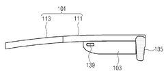
도 1은 본 발명의 다양한 실시예 중 하나에 따른 착용형 전자 장치를 나타내는 평면도이다. 도 2는 본 발명의 다양한 실시예 중 하나에 따른 착용형 전자 장치를 나타내는 분해 사시도이다. 1 is a plan view showing a wearable electronic device according to one of various embodiments of the present invention. Figure 2 is an exploded perspective view showing a wearable electronic device according to one of various embodiments of the present invention.
도 1 및 도 2를 참조하면, 본 발명의 다양한 실시예 중 하나에 따른 착용형 전자 장치(100)는 프레임(101), 바디부(103), 디스플레이 모듈(133) 및 가이드부(105)를 포함할 수 있다.1 and 2, a wearable
상기 프레임(101)은 사용자의 신체의 일부에 접하거나 안착될 수 있는 구조를 가질 수 있다. 상기 프레임(101)은 일반적인 안경 구조의 림(rim)과, 안경다리에 해당하는 템플(temple)의 역할을 제공할 수 있다. The
상기 프레임(101)은 제1 프레임(111), 제2 프레임(113) 및 제1 힌지부(115)를 포함할 수 있다. 상기 제1 프레임(111)은 사용자의 신체 일부(예: 얼굴)를 적어도 부분적으로 둘러싸는 형상으로서, 상기 바디부(103)에 연결되어 상기 바디부(103)를 지지하는 역할을 제공할 수 있다. 상기 제2 프레임(113)은 상기 제1 프레임(111)에 회동 가능하게 결합될 수 있다. 상기 제2 프레임(113)은 상기 제1 프레임(111)의 양단에서 각각 서로 나란하게 연장되어 사용자가 상기 전자 장치(100)를 신체, 예를 들면, 두부(head)에 착용할 수 있는 수단을 제공할 수 있다. 상기 제2 프레임(113)은 일반적인 안경 구조의 템플(temple)의 역할을 제공할 수 있다. 예컨대, 상기 제1 프레임(111)은 사용자의 안면 및 측면의 일부에 위치하며, 상기 한 쌍의 제2 프레임(113)은 사용자의 두부 양 옆에서 사용자의 귀에 안착될 수 있다. 상기 제1 힌지부(115)는 상기 제1 프레임(111)과 상기 제2 프레임(113)을 회동 가능하게 결합시킬 수 있다. 이에 따라, 상기 제2 프레임(113)은 상기 제1 프레임(111)에 대하여 회동하여 접힐 수 있으므로, 상기 착용형 전자 장치(100)가 차지하는 공간을 줄일 수 있게 되어 보관성과 휴대성을 향상시킬 수 있다.The
상기 바디부(103)는 상기 프레임(101)에 연결될 수 있다. 예컨대, 상기 바디부(103)는 상기 제1 프레임(111)에 연결될 수 있다. 상기 바디부(103)는 후술할 회로 기판(107) 및 센서(175)를 수용할 수 있다. The
상기 디스플레이 모듈(133)은 상기 바디부(103)에 장착될 수 있다. 상기 디스플레이 모듈(133)은 사용자의 시선 상에, 예를 들면, 사용자의 눈으로 직접 영상을 투사할 수 있다. 본 실시예에 따른 상기 디스플레이 모듈(133)은 한 쌍이 배치된 구성을 예시하고 있지만, 상기 디스플레이 모듈(133)은 하나만 배치될 수도 있다. 상기 디스플레이 모듈(133)은, 액정 디스플레이 소자나 유기발광 다이오드 등의 표시 소자와 광원 등을 구비함으로써, 영상을 출력할 수 있다.The
상기 가이드부(105)는 상기 프레임(101)에 대하여 상기 바디부(103)의 위치를 변화시킬 수 있다. 예컨대, 상기 가이드부(105)는 상기 프레임(101) 또는 상기 바디부(103)를 서로에 대하여 움직이게 함으로써, 상기 프레임(101)에 대하여 상기 바디부(103)의 상대적인 위치를 변화시킬 수 있다. 이에 따라, 상기 가이드부(105)는 상기 바디부(103)에 장착된 디스플레이 모듈(133)의 위치를 상기 프레임(101)에 대하여 상대적으로 변화시킬 수 있다. 이러한 가이드부(105)를 이용하여 상기 디스플레이 모듈(133)의 상기 프레임(101)에 대한 상대적인 위치를 변화시킴으로써, 사용자에 따른 다양한 얼굴 형상 및 눈의 위치 등에 따라 상기 디스플레이 모듈(133)로부터 출력되는 영상의 초점을 최적화할 수 있다. 상기 가이드부(105)의 구조에 대한 상세한 설명은 이후 도면을 통하여 살펴보기로 한다.The
본 발명의 다양한 실시예 중 하나에 따른 착용형 전자 장치(100)는 상기 프레임(101)에 설치되는 렌즈(135)를 더 포함할 수 있다. 예를 들면, 상기 디스플레이 모듈(133)로부터 출력된 영상이 상기 렌즈(135)에 결상될 수 있다.The wearable
상기 렌즈(135)는 상기 프레임(101)에 장착되어 사용자의 시선 상에, 예를 들면, 사용자의 양 눈(eye) 앞에 배치될 수 있다. 상기 렌즈(135)는 제1 렌즈(136), 제2 렌즈(137) 및 렌즈연결부재(138)를 포함할 수 있다. 상기 제1 렌즈(136)는 사용자의 어느 한 쪽 눈의 시선에 배치될 수 있다. 상기 제2 렌즈(137)는 사용자의 다른 한 쪽 눈의 시선에 배치될 수 있다. 상기 렌즈연결부재(138)는 상기 제1 렌즈(136)와 상기 제2 렌즈(137)를 연결할 수 있다. 상기 제1, 제2 렌즈(136, 137) 및 상기 렌즈연결부재(138)는 일반적인 안경 렌즈의 재질과 유사하거나, 전자변색 소재층(Electrochromic material layer)을 포함할 수 있다. 상기 전기변색 소재층은 전기변색 물질인 텅스텐 산화물, 몰리브덴 산화물, 티타늄 산화물, 바나듐 산화물, 이리듐 산화물, 니오브 산화물, 니켈 산화물(WO3, MoO3, TiO3, V2O5, IrO2, NbO5, NiO)으로 형성되거나, 이러한 물질들을 조합하여 형성할 수 있다. 이러한 전기변색 소재층은 전압을 인가받아 상기 렌즈(135)의 착색 농도를 조절함으로써, 빛의 투과율을 조절할 수 있다.The
본 발명의 다양한 실시예 중 하나에 따른 착용형 전자 장치(100)는 회로 기판(107), 배터리(108) 및 회로 배선(177)를 더 포함할 수 있다.The wearable
상기 회로 기판(107)들 중 하나는 상기 디스플레이 모듈(133)의 구동 회로, 상기 렌즈(135)의 착색 농도 조절을 위한 제어 회로, 화상 정보 등의 처리를 위한 프로세서를 포함하는 주회로 기판으로 제공될 수 있다. 상기 회로 기판(107)들 중 다른 하나는, 사용자와의 인터페이스, 다른 전자 장치나 상용 통신망의 접속을 제공하는 통신회로 및 각종 커넥터, 센서 모듈(175)이 탑재된 보조회로 기판으로 제공될 수 있다. 또한, 음향의 입출력을 위한 마이크로 폰, 스피커 폰 또한, 상기 회로 기판(107)들 중 하나에 배치되거나 상기 회로 기판(107)들 중 하나에 인접하게 배치될 수 있다. 물론, 상기 회로 기판(107)들의 회로 배치와 그에 따른 기능은 이에 한정되지 않으며, 필요에 따라 다양하게 조정될 수 있다. 예컨대, 상기 센서 모듈(175)은 상기 회로 기판(107)들 각각에 배치될 수 있다. 상기와 같은 회로 기판(107)들은 상기 바디부(103)들 중 어느 하나에 각각 배치될 수 있다. 상기 센서 모듈(175)은, 근접 센서, 조도 센서, 자이로 센서, 카메라 모듈, 시선 추적기, 지자기 센서, 가속도계 등을 포함할 수 있으며, 상기 센서 모듈(175)을 구성하는 각종 센서들이 반드시 상기 회로 기판(107)들 중 하나에 배치되는 것에 한정되지 않는다. 예컨대, 카메라 모듈은 사용자의 시선에 근접할 수 있게 상기 바디부(103) 상에서 적절한 위치, 예를 들면, 상기 렌즈(135)와 인접하는 위치에서 상기 바디부(103)에 장착될 수 있다. 상기와 같은 센서 모듈(175)은 상기 착용형 전자 장치(100)의 사용 환경 등을 감시하면서 최적의 사용 환경을 설정하는데 필요한 주변 환경에 대한 정보를 검출할 수 있다. 예컨대, 상기 센서 모듈(175)에 탑재된 조도 센서는 주변 조도를 검출하여 상기 렌즈(135)의 착색 농도 또는 상기 디스플레이 모듈(133)의 밝기와 해상도를 조절하는데 필요한 정보를 제공할 수 있다. 조도 센서를 배치함에 있어서, 사용자가 느끼는 주변의 조도와 가장 근접하는 조도를 검출할 수 있도록, 조도 센서는 사용자의 눈에 가장 근접하는 위치, 예를 들면, 상기 프레임(101) 상에서 렌즈(135)의 둘레에 장착될 수 있다. One of the
상기 배터리(108)는 상기 회로 기판(107), 디스플레이 모듈(133) 등에 전력을 제공하기 위한 것으로서, 상기 제2 프레임(113)들 중 적어도 하나에 수용될 수 있다. 예를 들어, 상기 제2 프레임(113)들 중 하나 또는 상기 제2 프레임(113)들 모두에 수용될 수 있다. The
그리고, 상기 제1 프레임(111)과 상기 제2 프레임(113)의 두께는 일정할 수 있다. 또한, 상기 제2 프레임(113)의 두께는 상기 배터리(108)의 두께와 대응될 수 있다. 예컨대, 상기 배터리(108)가 세워진 상태가 아닌 누운 상태로 상기 제2 프레임(113)에 수용될 수 있다. 즉, 상기 제2 프레임(113)은 상기 배터리(108)가 세워진 상태로 수용되는 구조에 비하여, 사용자와 불필요하게 접촉하는 면적을 줄일 수 있게 되어, 상기 착용형 전자 장치의 착용감을 향상시킬 수 있다. The thickness of the
상기 회로 배선(177)은 상기 프레임(101)을 통해 배선되어, 예를 들면, 상기 바디부(103)들 각각에 배치된 회로 기판(107)들을 서로 연결시킬 수 있다. 상기 회로 배선(177)은 주회로 기판과 보조회로 기판 사이에서 각종 제어 신호와 데이터의 송수신 경로를 제공하고, 상기 렌즈(135)나 디스플레이 모듈(133)의 제어 신호의 송수신 경로를 제공할 수 있다. 상기 회로 배선(177)의 기능과 역할은 다양하게 변경될 수 있으며, 그 수 또한 적절하게 조정될 수 있다. 상기 회로 배선(177)은 동축 케이블을 이용하여 구성될 수 있으며, 가요성 인쇄회로 기판(flexible printed circuit board; FPCB) 등 다른 다양한 형태의 전송 선로 구조를 가질 수 있다. The
상기와 같은 전자 장치(100)를 구성함에 있어, 상기 디스플레이 모듈(133)은 상기 제1, 제2 렌즈(136, 137) 중 하나와, 또는 한 쌍의 상기 디스플레이 모듈(133)들이 상기 제1, 제2 렌즈(136, 137)와 각각 대면하게 배치될 수 있다. 그리고, 상기 제1, 제2 렌즈(136, 137)가 배치되는 프레임(101)의 중앙부, 일반적인 안경 구조와 비교하면 브릿지(bridge)를 중심으로 상기 착용형 전자 장치(100)의 좌우의 무게 비율은 대칭, 예를 들면, 5:5를 이룰 수 있다. 아울러, 상기 제1 프레임(111)이 상기 착용형 전자 장치(100)의 전방에 위치하고, 상기 제2 프레임(113)이 상기 착용형 전자 장치(100)의 후방에 위치한다고 정의할 때, 상기 착용형 전자 장치(100)의 전후 무게 비율은 5:5내지 6:4를 이룰 수 있다. 이는 상기 렌즈(135), 상기 디스플레이 모듈(133)들, 상기 회로 기판(107)들 및 상기 배터리(108)들의 배치를 적절하게 분산함으로써 가능한 것이다. 이러한 무게 분산 구조를 통해 사용자가 상기 착용형 전자 장치(100)을 착용할 때, 특정 위치에 상기 착용형 전자 장치(100)의 무게가 집중되는 것을 방지하여 상기 착용형 전자 장치(100)의 착용감을 향상시킬 수 있다.In configuring the
도 3은 본 발명의 다양한 실시예 중 하나에 따른 착용형 전자 장치를 나타내는 정면도이다. 도 4는 본 발명의 다양한 실시예 중 하나에 따른 착용형 전자 장치를 나타내는 측면도이다.3 is a front view illustrating a wearable electronic device according to one of various embodiments of the present invention. 4 is a side view illustrating a wearable electronic device according to one of various embodiments of the present invention.
도 3 및 도 4를 참조하면, 본 발명의 다양한 실시예 중 하나에 따른 착용형 전자 장치(100)는 카메라 모듈(137) 및 터치패드(139)를 더 포함할 수 있다.3 and 4, a wearable
상기 카메라 모듈(137)은 전술한 바와 같이, 상기 회로 기판(107)에 탑재될 수 있으나, 이에 한정되지 않고, 상기 회로 기판(107)과 전기적으로 연결되어 상기 바디부(103)의 전방에 배치될 수 있다. 또한, 상기 카메라 모듈(137)이 배치되는 상기 바디부(103)의 전방에는 상기 카메라 모듈(137)이 배치되는 것에 한정되지 않고, 다양한 센서 모듈이 배치될 수 있다.The
상기 터치 패드(139)는 상기 바디부(103)에 배치되며, 상기 회로 기판(107)과 전기적으로 연결될 수 있다. 상기 터치 패드(139)는 사용자의 직접적인 접촉을 통하여 입력 신호를 발생시킬 수 있도록 상기 바디부(103)의 외부로 돌출될 수 있다. 또한, 상기 터치 패드(139)는 광학식 터치 패드 모듈로 구성될 수 있다. 이에 따라, 상기 터치 패드(139)는 사용자의 접촉뿐만 아니라 사용자의 제스쳐에 따라 입력 신호를 발생시켜, 사용자가 인식하는 화면에서 원하는 메뉴를 선택, 실행하거나 화면을 이동시킬 수 있다. The
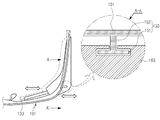
도 5는 본 발명의 다양한 실시예 중 하나에 따른 착용형 전자 장치의 가이드부를 나타내는 평면도이다. 5 is a plan view showing a guide portion of a wearable electronic device according to one of various embodiments of the present invention.
도 5를 참조하면, 상기 가이드부(105)는 상기 바디부(103)에 형성된 가이드홈(151) 및 상기 프레임(101)에서 연장되어 상기 가이드홈(151)에 삽입되는 삽입부(153)를 포함할 수 있다. 5, the
상기 가이드홈(151)은 상기 제1 프레임(111)에 인접하는 바디부(103)에 형성될 수 있다. 상기 가이드홈(151)은 상기 바디부(103)의 외부에서 슬릿 형태를 가질 수 있다. 상기 삽입부(153)는 상기 프레임(101)에서 상기 가이드홈(151)을 향하여 연장될 수 있다. 그리고, 상기 삽입부(153)의 일단은 상기 가이드홈(151)에 대응되어 상기 삽입부(153)에 삽입될 수 있다. 상기 삽입부(153)는 상기 가이드홈(151)의 길이방향을 따라 이동할 수 있다. 이러한 삽입부(153)의 이동에 따라, 상기 프레임(101)의 위치는 상기 바디부(103)에 대하여 상대적으로 변할 수 있다. 예컨대, 상기 바디부(103)에 장착된 디스플레이 모듈(133)의 위치를 사용자의 눈의 위치 등에 따라 조절 가능함에 따라, 상기 가이드부(105)는 사용자의 얼굴 또는 사용자의 눈의 위치 등에 따라 초점을 최적화할 수 있다. 구체적인 실시예에서, 상기 삽입부(153)가 움직이는 것으로 설명하고 있지만, 이러한 움직임은 결합된 두 부재, 예를 들면, 프레임(101)과 바디부(103))의 상대적인 움직임으로서, 상기 가이드홈(151)이 형성된 바디부(103)가 상기 프레임(101)에 대하여 상대적으로 움직일 수 있다. 즉, 상기 프레임(101)과 상기 바디부(103)의 상대적 위치가 변하게 되면, 상기 디스플레이 모듈(133)과 사용자의 눈의 상대적 위치를 변하게 하여 상기 디스플레이 모듈(133)에서 출력되는 영상의 초점을 맞출 수 있다.
The
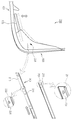
도 6은 본 발명의 다양한 실시예 중 다른 하나에 따른 착용형 전자 장치의 가이드부를 나타내는 평면도이다. 6 is a plan view showing a guide portion of a wearable electronic device according to another of various embodiments of the present invention.
도 6에 참조하면, 본 발명의 다양한 실시예 중 다른 하나에 따른 착용형 전자 장치(200)의 가이드부(201)는 제1 슬라이딩부(211) 및 제2 슬라이딩부(213)를 포함할 수 있다. 상기 제1 슬라이딩부(211)는 상기 바디부(103)에 제공되며, 길이방향을 따라 연장될 수 있다. 상기 제1 슬라이딩부(211)는 전술한 실시예의 가이드홈(151)의 길이방향과 교차하는 방향, 예를 들면 수직한 방향으로 형성될 수 있다. 상기 제2 슬라이딩부(213)는 상기 제1 슬라이딩부(211)와 결합하여 상기 제1 슬라이딩부(211)가 연장된 방향을 따라 슬라이딩 이동할 수 있다. 상기 제2 슬라이딩부(213)는 상기 디스플레이 모듈(133)에 연결되며, 상기 제2 슬라이딩부(213)가 상기 제1 슬라이딩부(211)의 안내를 받아 슬라이딩 이동하면, 상기 디스플레이 모듈(133)의 위치가 상기 바디부(103)에 대해, 또한 상기 프레임(101)에 대해 상대적으로 변할 수 있다. Referring to Figure 6, the
다양한 실시예에 따르면, 상기 디스플레이 모듈(133)은 상기 바디부(103)에 고정된 상태로 장착될 수 있다. 상기 디스플레이 모듈(133)이 상기 바디부(103)에 고정된다면, 상기 바디부(103)를 상기 프레임(101)에 대하여 이동 가능하게 함으로써, 상기 디스플레이 모듈(133)의 상기 프레임(101)에 대한 상대적이 위치를 조절할 수 있다. 예컨대, 상기 제1 슬라이딩부(211)를 상기 프레임(101)에 장착하고, 상기 제2 슬라이딩부(213)를 상기 바디부(103)에 장착함으로써, 상기 바디부(103)와 상기 바디부(103)에 고정된 디스플레이 모듈(133)이 상기 제1, 제2 슬라이딩부(211, 213)의 안내를 받아 상기 프레임(101)에 대하여 이동할 수 있다. According to various embodiments, the
또한, 전술한 실시예의 가이드부(105)와 본 실시예의 가이드부(201)를 함께 착용형 전자 장치(200)에 적용하게 되면, 상기 전자 장치(200)는 상기 프레임(101)에 대하여 전/후/좌/우로 상기 디스플레이 모듈(133)을 이동시켜, 다양한 사용자의 얼굴 형태 또는 눈의 위치에 따라 출력되는 영상의 초점을 최적화할 수 있다.When the
상기 제1, 제2 슬라이딩부(211, 213)를 포함하는 착용형 전자 장치(200)는 제1 멈춤부(231) 및 제2 멈춤부(233)를 더 포함할 수 있다.The wearable
상기 제1 멈춤부(231)는 상기 제1 슬라이딩부(211)에 형성될 수 있다. 상기 제2 멈춤부(233)는 상기 제2 슬라이딩부(213)에 제공될 수 있다. 상기 제2 멈춤부(233)는 상기 제2 슬라이딩부(213)에 복수 개로 형성될 수 있다. 상기 복수 개의 제2 멈춤부(233)는 서로 일정한 간격으로 배열될 수 있다. 다만, 상기 복수 개의 제2 멈춤부(233)는 일정한 간격으로 배열되는 것에 한정되지 않고, 인접하는 제2 멈춤부(233)들 사이의 간격은 서로 다르게 설정될 수 있다. 상기 제2 멈춤부(233)는 상기 제1 멈춤부(231)에 맞물릴 수 있다. 예컨대, 상기 제2 슬라이딩부(213)가 이동함에 따라 상기 제1 멈춤부(231)는 상기 제2 멈춤부(233)들 중 하나와 선택적으로 맞물릴 수 있다. 도 6에 도시된 바와 같이, 상기 제1 멈춤부(231)는 돌기로 이루어질 수 있다. 또한, 상기 제1 멈춤부(231)는 상기 제1 슬라이딩부(211)의 일면으로 돌출하게 설치된 판스프링일 수 있다. 다만, 상기 제1 멈춤부(231)는 돌기나 판스프링에 한정되지 않고, 탄성력을 가지면서 돌출된 다양한 형태를 가질 수 있다. 상기 제2 멈춤부(233)는 상기 제1 멈춤부(231)의 형상과 대응하는 개구부로 이루어질 수 있다. 상기 제1, 제2 슬라이딩부(211, 213)가 서로에 대하여 슬라이딩 이동함에 따라, 상기 제1 멈춤부(231)가 상기 제2 멈춤부(233)를 이루는 개구부들 중 하나에 맞물릴 수 있다. 상기 제1 멈춤부(231)가 상기 제2 멈춤부(233)를 이루는 개구부들 중 하나에 맞물림에 따라 상기 제1 슬라이딩부(211)는 상기 제2 슬라이딩부(213) 상에서 일정 위치에 정지된 상태를 유지할 수 있다.
The
도 7은 본 발명의 다양한 실시예 중 또 다른 하나에 따른 착용형 전자 장치를 나타내는 정면도이다.Figure 7 is a front view of a wearable electronic device according to another of the various embodiments of the present invention.
도 7에 도시된 바와 같이, 본 발명의 다양한 실시예 중 또 다른 하나에 따른 착용형 전자 장치(300)에 적용되는 프레임(301)은 제1 프레임(303) 및 제2 프레임(305)를 포함할 수 있으며, 상기 제1 프레임(303)은 프런트 프레임(331)과 사이드 프레임(305)과 제2 힌지부(335)를 포함할 수 있다7, a
상기 프런트 프레임(331)은 디스플레이 모듈(307)과 인접하게 배치되어 상기 디스플레이 모듈(307)을 지지하는 역할을 제공할 수 있다. 상기 사이드 프레임(333)은 상기 프런트 프레임(331)의 양단으로부터 각각 서로 나란하게 연장될 수 있다. 상기 사이드 프레임(333)은 상기 프런트 프레임(331)에 회동 가능하게 결합될 수 있다. 상기 사이드 프레임(333)에서는 상기 바디부와 마찬가지로, 회로 기판, 센서 모듈 또는 카메라 모듈이 장착될 수 있다. 상기 제2 힌지부(335)은 상기 프런트 프레임(331)과 상기 사이드 프레임(333)을 회동 가능하게 결합시킬 수 있다. 이에 따라, 상기 프런트 프레임(331)과 상기 사이드 프레임(335)을 포함하는 제1 프레임(303)은 접힐 수 있게 되어 상기 착용형 전자 장치(300)의 보관성 및 휴대성을 향상시킬 수 있다. 그리고, 상기 제2 프레임(305)은 상기 제1 프레임(305)의 일단에 회동 가능하게 결합될 수 있다. 상기 제2 프레임(305)에는 배터리가 장착될 수 있다. 또한, 상기 제1 프레임(303)과 상기 제2 프레임(305) 사이에 제1 힌지부(309)가 구비됨으로써, 상기 프레임(301)을 접을 수 있게 되어 상기 착용형 전자 장치(300)의 보관성 및 휴대성을 향상시킬 수 있다.
The
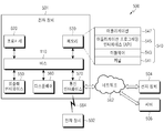
도 8은 본 발명의 다양한 실시예에 따른 착용형 전자 장치가 작동하는 네트워크 환경(500)을 나타내는 도면이다.8 is a diagram of a
도 8을 참조하면, 본 발명의 다양한 실시예들 중 하나에 따른 전자 장치는, 착용형 디스플레이 장치 (wearable display device), 스마트폰 (smartphone), 태블릿 PC (tablet personal computer), 이동 전화기 (mobile phone), 화상 전화기, 전자북 리더기 (e-book reader), 데스크탑 PC (desktop personal computer), 랩탑 PC (laptop personal computer), 넷북 컴퓨터 (netbook computer), 워크스테이션 (workstation), 서버, PDA (personal digital assistant), PMP (portable multimedia player), MP3 플레이어, 모바일 의료기기, 카메라 (camera), 또는 전자 의복, 전자 팔찌, 전자 목걸이, 전자 앱세서리 (appcessory), 전자 문신, 스마트 미러, 또는 스마트 와치 (smart watch) 중 적어도 하나를 포함할 수 있다. 8, an electronic device according to one of various embodiments of the present invention may be a wearable display device, a smartphone, a tablet personal computer, a mobile phone, ), A video phone, an e-book reader, a desktop personal computer, a laptop personal computer, a netbook computer, a workstation, a server, a personal digital assistant assistant, portable multimedia player (PMP), MP3 player, mobile medical device, camera or electronic apparel, electronic bracelet, electronic necklace, electronic apps, electronic tattoo, smart mirror, watch, and the like.
다양한 실시예들 중 다른 하나에 따르면, 전자 장치는 스마트 가전 제품 (smart home appliance)일 수 있다. 스마트 가전 제품은, 예를 들면, 텔레비전, DVD (digital video disk) 플레이어, 오디오, 냉장고, 에어컨, 청소기, 오븐, 전자레인지, 세탁기, 공기 청정기, 셋톱 박스 (set-top box), 홈 오토매이션 컨트롤 패널 (home automation control panel), 보안 컨트롤 패널 (security control panel), TV 박스 (예: 삼성 HomeSync™, 애플TV™ 또는 구글 TV™, 게임 콘솔 (예: Xbox™, PlayStation™), 전자 사전, 전자 키, 캠코더 (camcorder), 또는 전자 액자 중 적어도 하나를 포함할 수 있다.According to another of the various embodiments, the electronic device may be a smart home appliance. Smart home appliances include, for example, televisions, digital video disk players, audio, refrigerators, air conditioners, vacuum cleaners, ovens, microwaves, washing machines, air cleaners, set- You can use any of the following: a home automation control panel, a security control panel, a TV box such as Samsung HomeSync ™, Apple TV ™ or Google TV ™, a game console such as Xbox ™, PlayStation ™, An electronic key, a camcorder, or an electronic photo frame.
다양한 실시예들 중 또 다른 하나에 따르면, 전자 장치는, 각종 의료기기 (예: 각종 휴대용 의료측정기기 (혈당 측정기, 심박 측정기, 혈압 측정기, 또는 체온 측정기 등), MRA (magnetic resonance angiography), MRI (magnetic resonance imaging), CT (computed tomography), 촬영기, 또는 초음파기 등), 내비게이션 (navigation) 장치, GPS 수신기 (global positioning system receiver), EDR (event data recorder), FDR (flight data recorder), 자동차 인포테인먼트 (infotainment) 장치, 선박용 전자 장비(예: 선박용 항법 장치, 자이로 콤파스 등), 항공 전자기기 (avionics), 보안 기기, 차량용 헤드 유닛 (head unit), 산업용 또는 가정용 로봇, 금융 기관의 ATM (automatic teller? machine), 상점의 POS (point of sales), 또는 사물 인터넷 장치 (internet of things)(예: 전구, 각종 센서, 전기 또는 가스 미터기, 스프링클러 장치, 화재경보기, 온도조절기 (thermostat), 가로등, 토스터 (toaster), 운동기구, 온수탱크, 히터, 보일러 등) 중 적어도 하나를 포함할 수 있다.According to another of the various embodiments, the electronic device can be used in a variety of medical devices (e.g., various portable medical measurement devices such as blood glucose meters, heart rate meters, blood pressure meters or temperature meters), magnetic resonance angiography (MRA) (Global Positioning System) receiver, an event data recorder (EDR), a flight data recorder (FDR), an automotive infotainment system (ATMs), automatic teller machines (ATMs), automobiles, automobiles, automobiles, automobiles, automobiles, automobiles, a point of sale of a store or an internet of things such as a light bulb, various sensors, an electric or gas meter, a sprinkler device, a fire alarm, Group (thermostat), street lights, toaster (toaster), exercise equipment, hot water tank, a heater, boiler, etc.) may include at least one of.
다양한 실시예들 중 또 다른 하나에 따르면, 전자 장치는 가구 (furniture) 또는 건물/구조물의 일부, 전자 보드 (electronic board), 전자 사인 수신 장치 (electronic signature receiving device), 프로젝터 (projector), 또는 각종 계측 기기 (예: 수도, 전기, 가스, 또는 전파 계측 기기 등) 중 적어도 하나를 포함할 수 있다. 다양한 실시예에서, 전자 장치는 전술한 다양한 장치들 중 하나 또는 그 이상의 조합일 수 있다.According to another of the various embodiments, the electronic device is a piece of furniture or part of a building / structure, an electronic board, an electronic signature receiving device, a projector, (E.g., water, electricity, gas, or radio wave measuring instruments, etc.). In various embodiments, the electronic device may be a combination of one or more of the various devices described above.
도 8에 도시된 바와 같이, 상기 전자 장치 501는 버스 510, 프로세서 520, 메모리 530, 입출력 인터페이스 550, 디스플레이 560, 및 통신 인터페이스 570를 포함할 수 있다. 어떤 실시예에서는, 전자 장치 501는, 상기 구성요소들 중 적어도 하나를 생략하거나 다른 구성 요소를 추가적으로 구비할 수 있다. As shown in FIG. 8, the
상기 버스 510는, 예를 들면, 상기 구성요소들 510-570을 서로 연결하고, 상기 구성요소들 간의 통신 (예: 제어 메시지 및/또는 데이터)을 전달하는 회로를 포함할 수 있다.The bus 510 may include circuitry, for example, to connect the components 510-570 to each other and to communicate communications (e.g., control messages and / or data) between the components.
상기 프로세서 520는, 중앙처리장치 (central processing unit (CPU)), 어플리케이션 프로세서 (application processor (AP)), 또는 커뮤니케이션 프로세서 (communication processor(CP)) 중 하나 또는 그 이상을 포함할 수 있다. 상기 프로세서 520은, 예를 들면, 상기 전자 장치 501의 적어도 하나의 다른 구성요소들의 제어 및/또는 통신에 관한 연산이나 데이터 처리를 실행할 수 있다. The
상기 메모리 530는, 휘발성 및/또는 비휘발성 메모리를 포함할 수 있다. 상기 메모리 530는, 예를 들면, 상기 전자 장치 501의 적어도 하나의 다른 구성요소에 관계된 명령 또는 데이터를 저장할 수 있다. 한 실시예에 따르면, 상기 메모리 530는 소프트웨어 및/또는 프로그램 540을 저장할 수 있다. 상기 프로그램 540은, 예를 들면, 커널 541, 미들웨어 543, 어플리케이션 프로그래밍 인터페이스 (application programming interface (API)) 545, 및/또는 어플리케이션 프로그램 (또는 "어플리케이션" ) 547 등을 포함할 수 있다. 상기 커널 541, 미들웨어 543, 또는 API 545의 적어도 일부는, 운영 시스템 (operating system (OS))라 불릴 수 있다.The
상기 커널 541은, 예를 들면, 다른 프로그램들 (예: 미들웨어 543, API 545, 또는 어플리케이션 프로그램 547)에 구현된 동작 또는 기능을 실행하는 데 사용되는 시스템 리소스들 (예: 버스 510, 프로세서 520, 또는 메모리 530 등)을 제어 또는 관리할 수 있다. 또한, 상기 커널 541은 상기 미들웨어 543, 상기 API 545, 또는 상기 어플리케이션 프로그램 547에서 상기 전자 장치 501의 개별 구성요소에 접근함으로써, 시스템 리소스들을 제어 또는 관리할 수 있는 인터페이스를 제공할 수 있다. The
상기 미들웨어 543는, 예를 들면, 상기 API 545 또는 상기 어플리케이션 프로그램 547이 상기 커널 541과 통신하여 데이터를 주고받을 수 있도록 중개 역할을 수행할 수 있다. 또한, 상기 미들웨어 543는 상기 어플리케이션 프로그램 547로부터 수신된 작업 요청들과 관련하여, 예를 들면, 상기 어플리케이션 프로그램 547 중 적어도 하나의 어플리케이션에 상기 전자 장치 501의 시스템 리소스 (예: 버스 510, 프로세서 520, 또는 메모리 530 등)를 사용할 수 있는 우선 순위를 배정하는 등의 방법을 이용하여 작업 요청에 대한 제어 (예: 스케쥴링 또는 로드 밸런싱)을 수행할 수 있다.For example, the
상기 API 545는, 예를 들면, 상기 어플리케이션 547이 상기 커널 541 또는 상기 미들웨어 543에서 제공되는 기능을 제어하기 위한 인터페이스로, 예를 들면, 파일 제어, 창 제어, 화상 처리, 또는 문자 제어 등을 위한 적어도 하나의 인터페이스 또는 함수 (예: 명령어)를 포함할 수 있다. The
상기 입출력 인터페이스 550은, 예를 들면, 사용자 또는 다른 외부 기기로부터 입력된 명령 또는 데이터를 상기 전자 장치 501의 다른 구성요소(들)에 전달할 수 있는 인터페이스의 역할을 할 수 있다. 또한, 상기 입출력 인터페이스 550은 상기 전자 장치 501의 다른 구성요소(들)로부터 수신된 명령 또는 데이터를 사용자 또는 다른 외부 기기로 출력할 수 있다. The input /
상기 디스플레이 560은, 예를 들면, 액정 디스플레이 (LCD), 발광 다이오드 (LED) 디스플레이, 유기 발광 다이오드 (OLED) 디스플레이, 또는 마이크로 전자기계 시스템 (microelectromechanical systems (MEMS)) 디스플레이, 또는 전자종이 (electronic paper) 디스플레이를 포함할 수 있다. 상기 디스플레이 560은, 예를 들면, 사용자에게 각종 콘텐츠 (예: 텍스트, 이미지, 비디오, 아이콘, 또는 심볼 등)을 표시할 수 있다. 상기 디스플레이 560은, 터치 스크린을 포함할 수 있으며, 예를 들면, 전자 펜 또는 사용자의 신체의 일부를 이용한 터치, 제스쳐, 근접, 또는 호버링 입력을 수신할 수 있다.The
상기 통신 인터페이스 570은, 예를 들면, 상기 전자 장치 501와 외부 장치 (예: 제 1 외부 전자 장치 502, 제 2 외부 전자 장치 504, 또는 서버 506) 간의 통신을 설정할 수 있다. 예를 들면, 상기 통신 인터페이스 570은 무선 통신 또는 유선 통신을 통해서 네트워크 562에 연결되어 상기 외부 장치 (예: 제 2 외부 전자 장치 504 또는 서버 506)와 통신할 수 있다.The
상기 무선 통신은, 예를 들면, 셀룰러 통신 프로토콜로서, 예를 들면, LTE, LTE-A, CDMA, WCDMA, UMTS, WiBro, 또는 GSM 등 중 적어도 하나를 사용할 수 있다. 상기 유선 통신은, 예를 들면, USB (universal serial bus), HDMI (high definition multimedia interface), RS-232 (recommended standard 232), 또는 POTS (plain old telephone service) 등 중 적어도 하나를 포함할 수 있다. 상기 네트워크 562는 통신 네트워크 (telecommunications network), 예를 들면, 컴퓨터 네트워크 (computer network)(예: LAN 또는 WAN), 인터넷, 또는 전화 망 (telephone network) 중 적어도 하나를 포함할 수 있다.The wireless communication may use at least one of, for example, LTE, LTE-A, CDMA, WCDMA, UMTS, WiBro, or GSM as the cellular communication protocol. The wired communication may include at least one of a universal serial bus (USB), a high definition multimedia interface (HDMI), a recommended standard 232 (RS-232), a plain old telephone service (POTS) . The
상기 제 1 및 제 2 외부 전자 장치 502, 504 각각은 상기 전자 장치 501와 동일한 또는 다른 종류의 장치일 수 있다. 한 실시예에 따르면, 상기 서버 506는 하나 또는 그 이상의 서버들의 그룹을 포함할 수 있다.
다양한 실시예에 따르면, 상기 전자 장치 501에서 실행되는 동작들의 전부 또는 일부는 다른 하나 또는 복수의 전자 장치 (예: 전자 장치 502, 504, 또는 서버 506)에서 실행될 수 있다. 한 실시예에 따르면, 상기 전자 장치 501가 어떤 기능이나 서비스를 자동으로 또는 요청에 의하여 수행해야 할 경우에, 상기 전자 장치 501는 상기 기능 또는 상기 서비스를 자체적으로 실행시키는 대신에 또는 추가적으로, 그와 연관된 적어도 일부 기능을 다른 장치 (예: 전자 장치 502, 504, 또는 서버 506)에게 요청할 수 있다. 상기 다른 전자 장치 (예: 전자 장치 502, 504, 또는 서버 506)는 상기 요청된 기능 또는 추가 기능을 실행하고, 그 결과를 상기 전자 장치 501로 전달할 수 있다. 상기 전자 장치 501는 수신된 결과를 그대로 또는 추가적으로 처리하여 상기 요청된 기능이나 서비스를 제공할 수 있다. 이를 위하여, 예를 들면, 클라우드 컴퓨팅, 분산 컴퓨팅, 또는 클라이언트-서버 컴퓨팅 기술이 이용될 수 있다.
Each of the first and second external
이상, 본 발명의 상세한 설명에서는 구체적인 실시예에 관해서 설명하였으나, 본 발명의 범위에서 벗어나지 않는 한도 내에서 여러 가지 변형이 가능함은 당해 분야에서 통상의 지식을 가진 자에게 있어서 자명하다 할 것이다.While the present invention has been particularly shown and described with reference to exemplary embodiments thereof, it is to be understood that the invention is not limited to the disclosed exemplary embodiments.
100: 착용형 전자 장치 101: 프레임
111: 제1 프레임 113: 제2 프레임
115: 제1 힌지부 103: 바디부
133: 디스플레이부 135: 렌즈
105: 가이드부 107: 회로 기판
108: 배터리100: a wearable electronic device 101: a frame
111: first frame 113: second frame
115: first hinge part 103:
133: Display unit 135: Lens
105: guide portion 107: circuit board
108: Battery
Claims (18)
상기 프레임에 연결되는 바디부;
상기 바디부에 장착되며, 영상을 출력하는 디스플레이 모듈; 및
상기 프레임에 대하여 상기 디스플레이 모듈의 위치를 변화시키는 가이드부를 포함하는 착용형 전자 장치.
frame;
A body coupled to the frame;
A display module mounted on the body and outputting an image; And
And a guide portion for changing the position of the display module with respect to the frame.
상기 프레임에 설치된 렌즈를 더 포함하고,
상기 디스플레이 모듈로부터 출력된 영상이 상기 렌즈에 결상되는 착용형 전자 장치.
The method according to claim 1,
Further comprising a lens installed in the frame,
And an image output from the display module is imaged on the lens.
상기 바디부와 연결되는 제1 프레임;
상기 제1 프레임에 회동 가능하게 결합된 제2 프레임; 및
상기 제1, 제2 프레임을 회동 가능하게 결합시키는 제1 힌지부를 포함하는 착용형 전자 장치.
The apparatus of claim 1,
A first frame connected to the body part;
A second frame rotatably coupled to the first frame; And
And a first hinge portion for rotatably coupling the first and second frames.
상기 바디부에 수용되고 상기 디스플레이 모듈을 제어하는 회로 기판; 및
상기 제2 프레임에 수용되고 상기 디스플레이 모듈 및 상기 회로 기판에 전력을 제공하는 배터리를 더 포함하는 착용형 전자 장치.
The method of claim 3,
A circuit board accommodated in the body portion and controlling the display module; And
And a battery accommodated in the second frame and providing power to the display module and the circuit board.
상기 디스플레이 모듈과 인접하게 배치되는 프런트 프레임;
상기 프런트 프레임에 회동 가능하게 결합되는 사이드 프레임; 및
상기 프런트 프레임과 상기 사이드 프레임을 회동 가능하게 결합시키는 제2 힌지부를 포함하는 착용형 전자 장치.
The apparatus of claim 3, wherein the first frame comprises:
A front frame disposed adjacent to the display module;
A side frame rotatably coupled to the front frame; And
And a second hinge portion for pivotally connecting the front frame and the side frame.
상기 사이드 프레임에 수용되고, 상기 디스플레이 모듈을 제어하는 회로 기판; 및
상기 제2 프레임에 수용되고, 상기 디스플레이 모듈 및 상기 회로 기판에 전력을 제공하는 배터리를 더 포함하는 착용형 전자 장치.
6. The method of claim 5,
A circuit board accommodated in the side frame and controlling the display module; And
And a battery accommodated in the second frame and providing power to the display module and the circuit board.
상기 가이드부는 상기 바디부를 상기 프레임에 대해 이동시킴에 따라, 상기 디스플레이 모듈을 상기 프레임에 대해 이동시키는 착용형 전자 장치.
The display device according to claim 1, wherein the display module is fixed to the body portion,
Wherein the guide portion moves the display module relative to the frame as the body portion is moved relative to the frame.
상기 바디부에 형성된 가이드홈; 및
상기 프레임에서 연장되며, 상기 가이드홈에 삽입되는 삽입부를 포함하고,
상기 삽입부가 상기 가이드홈을 따라 이동하는 착용형 전자 장치.
8. The apparatus according to claim 7,
A guide groove formed in the body portion; And
An insertion portion extending from the frame and inserted into the guide groove,
And the insertion portion moves along the guide groove.
2. The wearable electronic device of claim 1, wherein as the display module moves within the body portion, the position of the display module changes relative to the frame.
상기 바디부에 길이방향을 따라 연장된 제1 슬라이딩부; 및
상기 디스플레이 모듈에 연결되며, 상기 제1 슬라이딩부를 따라 슬라이딩 이동하는 제2 슬라이딩부를 포함하는 착용형 전자 장치.
10. The apparatus according to claim 9,
A first sliding part extending along the longitudinal direction of the body part; And
And a second sliding portion connected to the display module and sliding along the first sliding portion.
상기 제1 슬라이딩부에 형성된 제1 멈춤부; 및
상기 제2 슬라이딩부에 제공되는 복수 개의 제2 멈춤부를 더 포함하고,
상기 제2 슬라이딩부가 이동함에 따라 상기 제1 멈춤부가 상기 제2 멈춤부들 중 하나와 선택적으로 맞물리는 착용형 전자 장치.
11. The apparatus according to claim 10,
A first stop formed on the first sliding portion; And
Further comprising a plurality of second stops provided on the second sliding portion,
And the first stop selectively engages one of the second stops as the second sliding portion moves.
상기 제2 멈춤부는 상기 돌기의 형상과 대응하는 개구부로 이루어지는 착용형 전자 장치.
12. The apparatus of claim 11, wherein the first stop comprises a projection,
And the second stop comprises an opening corresponding to the shape of the projection.
상기 바디부에 수용되는 복수 개의 회로 기판; 및
상기 프레임을 통해 배선되어 상기 회로 기판들을 연결시키는 회로 배선을 더 포함하는 착용형 전자 장치.
The method according to claim 1,
A plurality of circuit boards housed in the body portion; And
And circuit wiring wired through the frame to connect the circuit boards.
상기 바디부에 수용된 회로 기판; 및
상기 회로 기판에 탑재되는 센서 모듈 또는 카메라 모듈을 더 포함하는 착용형 전자 장치.
The method according to claim 1,
A circuit board accommodated in the body portion; And
And a sensor module or a camera module mounted on the circuit board.
상기 바디부에 배치되며, 사용자의 터치에 따라 입력신호를 발생하는 터치 패드를 더 포함하는 착용형 전자 장치.
The method according to claim 1,
And a touch pad disposed on the body portion and generating an input signal according to a user's touch.
사용자의 한 쪽 눈의 시선에 배치되는 제1 렌즈; 및
상기 사용자의 다른 한 쪽 눈의 시선에 배치되는 제2 렌즈를 포함하고,
상기 디스플레이 모듈이 상기 제1, 제2 렌즈 중 하나와, 또는 한 쌍의 상기 디스플레이 모듈들이 상기 제1, 제2 렌즈와 각각 대면하게 배치되는 착용형 전자 장치.
3. The objective lens of claim 2,
A first lens disposed at a line of sight of one eye of the user; And
And a second lens disposed in the line of sight of the other eye of the user,
Wherein the display module is disposed such that one of the first and second lenses, or a pair of the display modules, faces the first and second lenses, respectively.
17. The wearable electronic device according to claim 16, wherein the weight ratio of left and right is 5: 5 around the center of the frame in which the first and second lenses are arranged.
상기 디스플레이 모듈은 상기 렌즈에 인접하게 배치되어 상기 디스플레이 모듈로부터 출력된 영상을 상기 렌즈에 결상시키고,
상기 디스플레이 모듈의 이동에 따라 상기 렌즈에 대한 상기 디스플레이 모듈의 위치가 변화되어 상기 렌즈에 결상된 영상의 초점을 조절하는 착용형 디스플레이 장치.
2. The apparatus of claim 1, wherein the frame includes a first frame on which a lens is mounted and a second frame pivotally coupled to the first frame,
Wherein the display module is disposed adjacent to the lens to image an image output from the display module on the lens,
Wherein the position of the display module relative to the lens is changed according to the movement of the display module, thereby adjusting a focus of an image formed on the lens.
Priority Applications (2)
| Application Number | Priority Date | Filing Date | Title |
|---|---|---|---|
| KR1020140157259A KR102318788B1 (en) | 2014-11-12 | 2014-11-12 | Wearable electronic device |
| US14/939,512 US10073271B2 (en) | 2014-11-12 | 2015-11-12 | Wearable electronic device |
Applications Claiming Priority (1)
| Application Number | Priority Date | Filing Date | Title |
|---|---|---|---|
| KR1020140157259A KR102318788B1 (en) | 2014-11-12 | 2014-11-12 | Wearable electronic device |
Publications (2)
| Publication Number | Publication Date |
|---|---|
| KR20160056659A true KR20160056659A (en) | 2016-05-20 |
| KR102318788B1 KR102318788B1 (en) | 2021-10-29 |
Family
ID=55912119
Family Applications (1)
| Application Number | Title | Priority Date | Filing Date |
|---|---|---|---|
| KR1020140157259A KR102318788B1 (en) | 2014-11-12 | 2014-11-12 | Wearable electronic device |
Country Status (2)
| Country | Link |
|---|---|
| US (1) | US10073271B2 (en) |
| KR (1) | KR102318788B1 (en) |
Cited By (1)
| Publication number | Priority date | Publication date | Assignee | Title |
|---|---|---|---|---|
| WO2023128193A1 (en) * | 2021-12-30 | 2023-07-06 | 삼성전자주식회사 | Electronic device comprising connection member |
Families Citing this family (12)
| Publication number | Priority date | Publication date | Assignee | Title |
|---|---|---|---|---|
| US10444516B2 (en) * | 2017-04-05 | 2019-10-15 | North Inc. | Head-worn display apparatus having flexible stems |
| US10712159B2 (en) | 2017-04-10 | 2020-07-14 | Martha Grabowski | Critical system operations and simulations using wearable immersive augmented reality technology |
| EP3407120A1 (en) * | 2017-05-24 | 2018-11-28 | Sihto N.V. | Activation and interaction method of electronic eyeglasses |
| CN107390371A (en) * | 2017-09-22 | 2017-11-24 | 信利光电股份有限公司 | A kind of intelligent glasses |
| EP3690519B1 (en) * | 2017-09-25 | 2023-12-13 | Mitsui Chemicals, Inc. | Frame component, temple, frame, and eyewear |
| US11163155B1 (en) | 2017-12-18 | 2021-11-02 | Snap Inc. | Eyewear use detection |
| JP2020195105A (en) * | 2019-05-30 | 2020-12-03 | セイコーエプソン株式会社 | Wearing type display device |
| TWI761685B (en) * | 2019-06-24 | 2022-04-21 | 緯創資通股份有限公司 | Wearable disply device |
| US11714285B1 (en) * | 2019-07-22 | 2023-08-01 | Apple Inc. | Head-mountable device with head securement mechanism |
| US11513578B1 (en) * | 2020-02-03 | 2022-11-29 | Meta Platforms Technologies, Llc | Power management system for an artificial reality system |
| US20210302751A1 (en) * | 2020-03-31 | 2021-09-30 | Brockman-Hastings LLC | Reversible earpiece, head-mounted device with reversible earpiece and related method |
| US11512952B1 (en) * | 2021-06-30 | 2022-11-29 | Microsoft Technology Licensing, Llc | Enhanced detection of sensor misalignments by coordinating sensors utilizing multiple sensing modalities |
Citations (6)
| Publication number | Priority date | Publication date | Assignee | Title |
|---|---|---|---|---|
| JP2010102077A (en) * | 2008-10-23 | 2010-05-06 | Sony Corp | Head-mounted display |
| JP2010224472A (en) * | 2009-03-25 | 2010-10-07 | Olympus Corp | Spectacle mount type image display apparatus |
| JP2010226660A (en) * | 2009-03-25 | 2010-10-07 | Olympus Corp | Spectacle mount type image display device |
| JP2010226661A (en) * | 2009-03-25 | 2010-10-07 | Olympus Corp | Spectacle mount type image display device |
| JP2013238813A (en) * | 2012-05-17 | 2013-11-28 | Olympus Corp | Head-mounted display device |
| KR20140053341A (en) * | 2011-08-18 | 2014-05-07 | 구글 인코포레이티드 | Wearable device with input and output structures |
Family Cites Families (9)
| Publication number | Priority date | Publication date | Assignee | Title |
|---|---|---|---|---|
| JP2011160166A (en) | 2010-01-30 | 2011-08-18 | Brother Industries Ltd | Frame structure for head mount display and head mount display |
| KR20120139241A (en) | 2011-06-17 | 2012-12-27 | 크레신 주식회사 | Liquid crystal shutter driving apparatus separate type stereoscopic images watching system |
| US8223024B1 (en) | 2011-09-21 | 2012-07-17 | Google Inc. | Locking mechanism based on unnatural movement of head-mounted display |
| US8941560B2 (en) | 2011-09-21 | 2015-01-27 | Google Inc. | Wearable computer with superimposed controls and instructions for external device |
| US20130176626A1 (en) | 2012-01-05 | 2013-07-11 | Google Inc. | Wearable device assembly with input and output structures |
| US9075249B2 (en) * | 2012-03-07 | 2015-07-07 | Google Inc. | Eyeglass frame with input and output functionality |
| AT513833B1 (en) * | 2013-02-22 | 2014-08-15 | Silhouette Int Schmied Ag | Hinge joint for a pair of glasses |
| US20140253867A1 (en) * | 2013-03-05 | 2014-09-11 | Tao Jiang | Pair of Projector Glasses |
| US9436009B1 (en) * | 2013-06-28 | 2016-09-06 | Google Inc. | Modular accessories for head-mountable device |
-
2014
- 2014-11-12 KR KR1020140157259A patent/KR102318788B1/en active IP Right Grant
-
2015
- 2015-11-12 US US14/939,512 patent/US10073271B2/en not_active Expired - Fee Related
Patent Citations (6)
| Publication number | Priority date | Publication date | Assignee | Title |
|---|---|---|---|---|
| JP2010102077A (en) * | 2008-10-23 | 2010-05-06 | Sony Corp | Head-mounted display |
| JP2010224472A (en) * | 2009-03-25 | 2010-10-07 | Olympus Corp | Spectacle mount type image display apparatus |
| JP2010226660A (en) * | 2009-03-25 | 2010-10-07 | Olympus Corp | Spectacle mount type image display device |
| JP2010226661A (en) * | 2009-03-25 | 2010-10-07 | Olympus Corp | Spectacle mount type image display device |
| KR20140053341A (en) * | 2011-08-18 | 2014-05-07 | 구글 인코포레이티드 | Wearable device with input and output structures |
| JP2013238813A (en) * | 2012-05-17 | 2013-11-28 | Olympus Corp | Head-mounted display device |
Cited By (1)
| Publication number | Priority date | Publication date | Assignee | Title |
|---|---|---|---|---|
| WO2023128193A1 (en) * | 2021-12-30 | 2023-07-06 | 삼성전자주식회사 | Electronic device comprising connection member |
Also Published As
| Publication number | Publication date |
|---|---|
| KR102318788B1 (en) | 2021-10-29 |
| US20160131913A1 (en) | 2016-05-12 |
| US10073271B2 (en) | 2018-09-11 |
Similar Documents
| Publication | Publication Date | Title |
|---|---|---|
| KR102318788B1 (en) | Wearable electronic device | |
| KR102253154B1 (en) | Wearable electronic device | |
| US10168772B2 (en) | Head mounted electronic device | |
| CN106802482B (en) | Coupler and head-mounted display device | |
| US10684654B2 (en) | Head-mounted display device with detachable device | |
| KR102244222B1 (en) | A method for providing a visual reality service and apparatuses therefor | |
| US9316836B2 (en) | Wearable device with input and output structures | |
| EP3580638B1 (en) | System and method for two dimensional application usage in three dimensional virtual reality environment | |
| TWI607240B (en) | Eyeglass frame with input and output functionality | |
| CN111492298A (en) | Systems and methods for configuring HMDs for various mobile device sizes | |
| CN111936913A (en) | Electronic device capable of adjusting distance between shells | |
| KR20160059765A (en) | Method and device for displaying in electronic device | |
| KR20170097516A (en) | Electronic device and manufacturing method thereof | |
| KR20180076790A (en) | Camera module providing ois function and electronic device comprising the same | |
| KR102641881B1 (en) | Electronic device and method for acquiring omnidirectional image | |
| KR102492607B1 (en) | Sports goggle | |
| US20230152900A1 (en) | Wearable electronic device for displaying virtual object and method of controlling the same | |
| EP3383037B1 (en) | Content display method and electronic device for performing same | |
| US20230204985A1 (en) | Wearable electronic device | |
| US10249156B2 (en) | Method for providing haptic effect and electronic device thererfor | |
| KR20230071680A (en) | Waearable electronic device displaying virtual object and method for controlling the same | |
| KR20220080387A (en) | Lens clip where user lens is inserted and head mounted electronic device detecting whether user lens is inserted in lens clip |
Legal Events
| Date | Code | Title | Description |
|---|---|---|---|
| A201 | Request for examination | ||
| E902 | Notification of reason for refusal | ||
| AMND | Amendment | ||
| E601 | Decision to refuse application | ||
| AMND | Amendment | ||
| X701 | Decision to grant (after re-examination) |