KR20160055152A - Polarizing plate, method for manufacturing polarizing plate, image display device, method for manufacturing image display device, and method for improving transmittance of polarizing plate - Google Patents
Polarizing plate, method for manufacturing polarizing plate, image display device, method for manufacturing image display device, and method for improving transmittance of polarizing plate Download PDFInfo
- Publication number
- KR20160055152A KR20160055152A KR1020167006638A KR20167006638A KR20160055152A KR 20160055152 A KR20160055152 A KR 20160055152A KR 1020167006638 A KR1020167006638 A KR 1020167006638A KR 20167006638 A KR20167006638 A KR 20167006638A KR 20160055152 A KR20160055152 A KR 20160055152A
- Authority
- KR
- South Korea
- Prior art keywords
- light
- polarizer
- polarizing plate
- refractive index
- plane
- Prior art date
- Legal status (The legal status is an assumption and is not a legal conclusion. Google has not performed a legal analysis and makes no representation as to the accuracy of the status listed.)
- Withdrawn
Links
- 238000002834 transmittance Methods 0.000 title claims abstract description 85
- 238000004519 manufacturing process Methods 0.000 title claims description 29
- 238000000034 method Methods 0.000 title claims description 22
- 239000000463 material Substances 0.000 claims abstract description 104
- 239000000758 substrate Substances 0.000 claims abstract description 101
- 230000005540 biological transmission Effects 0.000 claims description 63
- 239000004973 liquid crystal related substance Substances 0.000 claims description 30
- 230000003287 optical effect Effects 0.000 claims description 6
- 239000013307 optical fiber Substances 0.000 claims 1
- 239000006185 dispersion Substances 0.000 description 52
- 230000000052 comparative effect Effects 0.000 description 25
- 229920000728 polyester Polymers 0.000 description 25
- -1 polyethylene terephthalate Polymers 0.000 description 16
- 230000010287 polarization Effects 0.000 description 13
- 229920000139 polyethylene terephthalate Polymers 0.000 description 13
- 239000005020 polyethylene terephthalate Substances 0.000 description 13
- 229920002678 cellulose Polymers 0.000 description 10
- 229920000089 Cyclic olefin copolymer Polymers 0.000 description 8
- 238000004364 calculation method Methods 0.000 description 8
- 210000002858 crystal cell Anatomy 0.000 description 8
- 238000005259 measurement Methods 0.000 description 7
- 239000010410 layer Substances 0.000 description 6
- 230000001681 protective effect Effects 0.000 description 6
- 229920002554 vinyl polymer Polymers 0.000 description 6
- 229920006267 polyester film Polymers 0.000 description 5
- 229920002284 Cellulose triacetate Polymers 0.000 description 4
- NNLVGZFZQQXQNW-ADJNRHBOSA-N [(2r,3r,4s,5r,6s)-4,5-diacetyloxy-3-[(2s,3r,4s,5r,6r)-3,4,5-triacetyloxy-6-(acetyloxymethyl)oxan-2-yl]oxy-6-[(2r,3r,4s,5r,6s)-4,5,6-triacetyloxy-2-(acetyloxymethyl)oxan-3-yl]oxyoxan-2-yl]methyl acetate Chemical compound O([C@@H]1O[C@@H]([C@H]([C@H](OC(C)=O)[C@H]1OC(C)=O)O[C@H]1[C@@H]([C@@H](OC(C)=O)[C@H](OC(C)=O)[C@@H](COC(C)=O)O1)OC(C)=O)COC(=O)C)[C@@H]1[C@@H](COC(C)=O)O[C@@H](OC(C)=O)[C@H](OC(C)=O)[C@H]1OC(C)=O NNLVGZFZQQXQNW-ADJNRHBOSA-N 0.000 description 4
- 238000000926 separation method Methods 0.000 description 4
- 125000000391 vinyl group Chemical group [H]C([*])=C([H])[H] 0.000 description 4
- YMWUJEATGCHHMB-UHFFFAOYSA-N Dichloromethane Chemical compound ClCCl YMWUJEATGCHHMB-UHFFFAOYSA-N 0.000 description 3
- 238000010521 absorption reaction Methods 0.000 description 3
- 239000011521 glass Substances 0.000 description 3
- 239000012770 industrial material Substances 0.000 description 3
- 239000011159 matrix material Substances 0.000 description 3
- 229920003207 poly(ethylene-2,6-naphthalate) Polymers 0.000 description 3
- 239000011112 polyethylene naphthalate Substances 0.000 description 3
- 229920005989 resin Polymers 0.000 description 3
- 239000011347 resin Substances 0.000 description 3
- 238000012360 testing method Methods 0.000 description 3
- OAICVXFJPJFONN-UHFFFAOYSA-N Phosphorus Chemical compound [P] OAICVXFJPJFONN-UHFFFAOYSA-N 0.000 description 2
- 125000003118 aryl group Chemical group 0.000 description 2
- 230000008033 biological extinction Effects 0.000 description 2
- 150000001875 compounds Chemical class 0.000 description 2
- 230000000694 effects Effects 0.000 description 2
- 238000010438 heat treatment Methods 0.000 description 2
- 238000010030 laminating Methods 0.000 description 2
- 230000035699 permeability Effects 0.000 description 2
- 239000004065 semiconductor Substances 0.000 description 2
- 238000001228 spectrum Methods 0.000 description 2
- 238000003892 spreading Methods 0.000 description 2
- ZCYVEMRRCGMTRW-UHFFFAOYSA-N 7553-56-2 Chemical compound [I] ZCYVEMRRCGMTRW-UHFFFAOYSA-N 0.000 description 1
- 229920008347 Cellulose acetate propionate Polymers 0.000 description 1
- 239000004372 Polyvinyl alcohol Substances 0.000 description 1
- 235000010724 Wisteria floribunda Nutrition 0.000 description 1
- DHKHKXVYLBGOIT-UHFFFAOYSA-N acetaldehyde Diethyl Acetal Natural products CCOC(C)OCC DHKHKXVYLBGOIT-UHFFFAOYSA-N 0.000 description 1
- 150000001241 acetals Chemical class 0.000 description 1
- 239000002253 acid Substances 0.000 description 1
- NIXOWILDQLNWCW-UHFFFAOYSA-N acrylic acid group Chemical group C(C=C)(=O)O NIXOWILDQLNWCW-UHFFFAOYSA-N 0.000 description 1
- 239000000853 adhesive Substances 0.000 description 1
- 230000001070 adhesive effect Effects 0.000 description 1
- 239000012790 adhesive layer Substances 0.000 description 1
- JNDMLEXHDPKVFC-UHFFFAOYSA-N aluminum;oxygen(2-);yttrium(3+) Chemical compound [O-2].[O-2].[O-2].[Al+3].[Y+3] JNDMLEXHDPKVFC-UHFFFAOYSA-N 0.000 description 1
- DQXBYHZEEUGOBF-UHFFFAOYSA-N but-3-enoic acid;ethene Chemical compound C=C.OC(=O)CC=C DQXBYHZEEUGOBF-UHFFFAOYSA-N 0.000 description 1
- 229920001577 copolymer Polymers 0.000 description 1
- 238000007334 copolymerization reaction Methods 0.000 description 1
- 238000003851 corona treatment Methods 0.000 description 1
- 238000010586 diagram Methods 0.000 description 1
- 150000002009 diols Chemical class 0.000 description 1
- 208000028659 discharge Diseases 0.000 description 1
- 238000002845 discoloration Methods 0.000 description 1
- 238000000295 emission spectrum Methods 0.000 description 1
- 239000005038 ethylene vinyl acetate Substances 0.000 description 1
- 238000011156 evaluation Methods 0.000 description 1
- 230000002349 favourable effect Effects 0.000 description 1
- 238000011835 investigation Methods 0.000 description 1
- 229910052740 iodine Inorganic materials 0.000 description 1
- 239000011630 iodine Substances 0.000 description 1
- 230000001678 irradiating effect Effects 0.000 description 1
- 238000003475 lamination Methods 0.000 description 1
- 239000000178 monomer Substances 0.000 description 1
- 230000010355 oscillation Effects 0.000 description 1
- 229920001200 poly(ethylene-vinyl acetate) Polymers 0.000 description 1
- 229920001707 polybutylene terephthalate Polymers 0.000 description 1
- 229920000515 polycarbonate Polymers 0.000 description 1
- 239000004417 polycarbonate Substances 0.000 description 1
- 229920006254 polymer film Polymers 0.000 description 1
- 229920002451 polyvinyl alcohol Polymers 0.000 description 1
- 239000002243 precursor Substances 0.000 description 1
- 238000002310 reflectometry Methods 0.000 description 1
- 238000007127 saponification reaction Methods 0.000 description 1
- 229920006395 saturated elastomer Polymers 0.000 description 1
- 239000007787 solid Substances 0.000 description 1
- 230000003595 spectral effect Effects 0.000 description 1
- 238000004381 surface treatment Methods 0.000 description 1
- 238000010998 test method Methods 0.000 description 1
- 239000012780 transparent material Substances 0.000 description 1
- 229910019901 yttrium aluminum garnet Inorganic materials 0.000 description 1
Images

Classifications
-
- B—PERFORMING OPERATIONS; TRANSPORTING
- B32—LAYERED PRODUCTS
- B32B—LAYERED PRODUCTS, i.e. PRODUCTS BUILT-UP OF STRATA OF FLAT OR NON-FLAT, e.g. CELLULAR OR HONEYCOMB, FORM
- B32B7/00—Layered products characterised by the relation between layers; Layered products characterised by the relative orientation of features between layers, or by the relative values of a measurable parameter between layers, i.e. products comprising layers having different physical, chemical or physicochemical properties; Layered products characterised by the interconnection of layers
- B32B7/02—Physical, chemical or physicochemical properties
-
- G—PHYSICS
- G02—OPTICS
- G02B—OPTICAL ELEMENTS, SYSTEMS OR APPARATUS
- G02B27/00—Optical systems or apparatus not provided for by any of the groups G02B1/00 - G02B26/00, G02B30/00
- G02B27/28—Optical systems or apparatus not provided for by any of the groups G02B1/00 - G02B26/00, G02B30/00 for polarising
- G02B27/283—Optical systems or apparatus not provided for by any of the groups G02B1/00 - G02B26/00, G02B30/00 for polarising used for beam splitting or combining
-
- G—PHYSICS
- G02—OPTICS
- G02B—OPTICAL ELEMENTS, SYSTEMS OR APPARATUS
- G02B5/00—Optical elements other than lenses
- G02B5/30—Polarising elements
- G02B5/3025—Polarisers, i.e. arrangements capable of producing a definite output polarisation state from an unpolarised input state
-
- G—PHYSICS
- G02—OPTICS
- G02B—OPTICAL ELEMENTS, SYSTEMS OR APPARATUS
- G02B5/00—Optical elements other than lenses
- G02B5/30—Polarising elements
- G02B5/3025—Polarisers, i.e. arrangements capable of producing a definite output polarisation state from an unpolarised input state
- G02B5/3033—Polarisers, i.e. arrangements capable of producing a definite output polarisation state from an unpolarised input state in the form of a thin sheet or foil, e.g. Polaroid
- G02B5/3041—Polarisers, i.e. arrangements capable of producing a definite output polarisation state from an unpolarised input state in the form of a thin sheet or foil, e.g. Polaroid comprising multiple thin layers, e.g. multilayer stacks
- G02B5/305—Polarisers, i.e. arrangements capable of producing a definite output polarisation state from an unpolarised input state in the form of a thin sheet or foil, e.g. Polaroid comprising multiple thin layers, e.g. multilayer stacks including organic materials, e.g. polymeric layers
-
- G—PHYSICS
- G02—OPTICS
- G02B—OPTICAL ELEMENTS, SYSTEMS OR APPARATUS
- G02B5/00—Optical elements other than lenses
- G02B5/30—Polarising elements
- G02B5/3083—Birefringent or phase retarding elements
-
- G—PHYSICS
- G02—OPTICS
- G02F—OPTICAL DEVICES OR ARRANGEMENTS FOR THE CONTROL OF LIGHT BY MODIFICATION OF THE OPTICAL PROPERTIES OF THE MEDIA OF THE ELEMENTS INVOLVED THEREIN; NON-LINEAR OPTICS; FREQUENCY-CHANGING OF LIGHT; OPTICAL LOGIC ELEMENTS; OPTICAL ANALOGUE/DIGITAL CONVERTERS
- G02F1/00—Devices or arrangements for the control of the intensity, colour, phase, polarisation or direction of light arriving from an independent light source, e.g. switching, gating or modulating; Non-linear optics
- G02F1/01—Devices or arrangements for the control of the intensity, colour, phase, polarisation or direction of light arriving from an independent light source, e.g. switching, gating or modulating; Non-linear optics for the control of the intensity, phase, polarisation or colour
- G02F1/13—Devices or arrangements for the control of the intensity, colour, phase, polarisation or direction of light arriving from an independent light source, e.g. switching, gating or modulating; Non-linear optics for the control of the intensity, phase, polarisation or colour based on liquid crystals, e.g. single liquid crystal display cells
- G02F1/133—Constructional arrangements; Operation of liquid crystal cells; Circuit arrangements
- G02F1/1333—Constructional arrangements; Manufacturing methods
- G02F1/1335—Structural association of cells with optical devices, e.g. polarisers or reflectors
- G02F1/133528—Polarisers
-
- G—PHYSICS
- G02—OPTICS
- G02F—OPTICAL DEVICES OR ARRANGEMENTS FOR THE CONTROL OF LIGHT BY MODIFICATION OF THE OPTICAL PROPERTIES OF THE MEDIA OF THE ELEMENTS INVOLVED THEREIN; NON-LINEAR OPTICS; FREQUENCY-CHANGING OF LIGHT; OPTICAL LOGIC ELEMENTS; OPTICAL ANALOGUE/DIGITAL CONVERTERS
- G02F1/00—Devices or arrangements for the control of the intensity, colour, phase, polarisation or direction of light arriving from an independent light source, e.g. switching, gating or modulating; Non-linear optics
- G02F1/01—Devices or arrangements for the control of the intensity, colour, phase, polarisation or direction of light arriving from an independent light source, e.g. switching, gating or modulating; Non-linear optics for the control of the intensity, phase, polarisation or colour
- G02F1/13—Devices or arrangements for the control of the intensity, colour, phase, polarisation or direction of light arriving from an independent light source, e.g. switching, gating or modulating; Non-linear optics for the control of the intensity, phase, polarisation or colour based on liquid crystals, e.g. single liquid crystal display cells
- G02F1/133—Constructional arrangements; Operation of liquid crystal cells; Circuit arrangements
- G02F1/1333—Constructional arrangements; Manufacturing methods
- G02F1/1335—Structural association of cells with optical devices, e.g. polarisers or reflectors
- G02F1/1336—Illuminating devices
- G02F1/13362—Illuminating devices providing polarized light, e.g. by converting a polarisation component into another one
-
- B—PERFORMING OPERATIONS; TRANSPORTING
- B32—LAYERED PRODUCTS
- B32B—LAYERED PRODUCTS, i.e. PRODUCTS BUILT-UP OF STRATA OF FLAT OR NON-FLAT, e.g. CELLULAR OR HONEYCOMB, FORM
- B32B2307/00—Properties of the layers or laminate
- B32B2307/40—Properties of the layers or laminate having particular optical properties
- B32B2307/418—Refractive
-
- B—PERFORMING OPERATIONS; TRANSPORTING
- B32—LAYERED PRODUCTS
- B32B—LAYERED PRODUCTS, i.e. PRODUCTS BUILT-UP OF STRATA OF FLAT OR NON-FLAT, e.g. CELLULAR OR HONEYCOMB, FORM
- B32B2457/00—Electrical equipment
- B32B2457/20—Displays, e.g. liquid crystal displays, plasma displays
- B32B2457/202—LCD, i.e. liquid crystal displays
-
- B—PERFORMING OPERATIONS; TRANSPORTING
- B32—LAYERED PRODUCTS
- B32B—LAYERED PRODUCTS, i.e. PRODUCTS BUILT-UP OF STRATA OF FLAT OR NON-FLAT, e.g. CELLULAR OR HONEYCOMB, FORM
- B32B2551/00—Optical elements
-
- G—PHYSICS
- G02—OPTICS
- G02F—OPTICAL DEVICES OR ARRANGEMENTS FOR THE CONTROL OF LIGHT BY MODIFICATION OF THE OPTICAL PROPERTIES OF THE MEDIA OF THE ELEMENTS INVOLVED THEREIN; NON-LINEAR OPTICS; FREQUENCY-CHANGING OF LIGHT; OPTICAL LOGIC ELEMENTS; OPTICAL ANALOGUE/DIGITAL CONVERTERS
- G02F1/00—Devices or arrangements for the control of the intensity, colour, phase, polarisation or direction of light arriving from an independent light source, e.g. switching, gating or modulating; Non-linear optics
- G02F1/01—Devices or arrangements for the control of the intensity, colour, phase, polarisation or direction of light arriving from an independent light source, e.g. switching, gating or modulating; Non-linear optics for the control of the intensity, phase, polarisation or colour
- G02F1/13—Devices or arrangements for the control of the intensity, colour, phase, polarisation or direction of light arriving from an independent light source, e.g. switching, gating or modulating; Non-linear optics for the control of the intensity, phase, polarisation or colour based on liquid crystals, e.g. single liquid crystal display cells
- G02F1/133—Constructional arrangements; Operation of liquid crystal cells; Circuit arrangements
- G02F1/1333—Constructional arrangements; Manufacturing methods
- G02F1/1335—Structural association of cells with optical devices, e.g. polarisers or reflectors
- G02F1/133528—Polarisers
- G02F1/133531—Polarisers characterised by the arrangement of polariser or analyser axes
-
- G—PHYSICS
- G02—OPTICS
- G02F—OPTICAL DEVICES OR ARRANGEMENTS FOR THE CONTROL OF LIGHT BY MODIFICATION OF THE OPTICAL PROPERTIES OF THE MEDIA OF THE ELEMENTS INVOLVED THEREIN; NON-LINEAR OPTICS; FREQUENCY-CHANGING OF LIGHT; OPTICAL LOGIC ELEMENTS; OPTICAL ANALOGUE/DIGITAL CONVERTERS
- G02F1/00—Devices or arrangements for the control of the intensity, colour, phase, polarisation or direction of light arriving from an independent light source, e.g. switching, gating or modulating; Non-linear optics
- G02F1/01—Devices or arrangements for the control of the intensity, colour, phase, polarisation or direction of light arriving from an independent light source, e.g. switching, gating or modulating; Non-linear optics for the control of the intensity, phase, polarisation or colour
- G02F1/13—Devices or arrangements for the control of the intensity, colour, phase, polarisation or direction of light arriving from an independent light source, e.g. switching, gating or modulating; Non-linear optics for the control of the intensity, phase, polarisation or colour based on liquid crystals, e.g. single liquid crystal display cells
- G02F1/133—Constructional arrangements; Operation of liquid crystal cells; Circuit arrangements
- G02F1/1333—Constructional arrangements; Manufacturing methods
- G02F1/1335—Structural association of cells with optical devices, e.g. polarisers or reflectors
- G02F1/133528—Polarisers
- G02F1/13355—Polarising beam splitters [PBS]
Landscapes
- Physics & Mathematics (AREA)
- General Physics & Mathematics (AREA)
- Optics & Photonics (AREA)
- Nonlinear Science (AREA)
- Mathematical Physics (AREA)
- Chemical & Material Sciences (AREA)
- Crystallography & Structural Chemistry (AREA)
- Polarising Elements (AREA)
- Liquid Crystal (AREA)
Abstract
면 내에 위상차를 갖지 않는 광 투과성 기재가 사용된 경우라도, 광 투과율이 우수한 편광판을 제공한다. 백라이트 광원 측으로부터, 적어도, 면 내에 복굴절률을 갖는 광 투과성 기재와 편광자가 이 순서대로 적층되고, 화상 표시 장치의 상기 백라이트 광원 측에 배치해서 사용되는 편광판이며, 상기 면 내에 복굴절률을 갖는 광 투과성 기재에, 편광된 광이 입사되는 것이고, 상기 면 내에 복굴절률을 갖는 광 투과성 기재와 상기 편광자는, 상기 면 내에 복굴절률을 갖는 광 투과성 기재의 굴절률이 작은 방향인 진상축과 상기 편광자의 투과축이 이루는 각도가, 0°±30°또는 90°±30°로 되도록 적층되어 있는 것을 특징으로 하는 편광판.Even when a light-transmitting base material having no retardation in a plane is used, a polarizing plate having excellent light transmittance is provided. A polarizing plate which is laminated at least on a light transmitting base material having a birefringent index in a plane and a polarizer in this order from the back light source side and is disposed on the backlight light source side of the image display device and has a light transmittance Wherein a polarizing element and a polarizing element having a birefringent index in the plane are incident on the substrate and the polarizer is a polarizing element having a phase difference between a fast axis which is a direction in which a refractive index of a light- Is formed so as to be 0 DEG +/- 30 DEG or 90 DEG +/- 30 DEG.
Description
본 발명은, 편광판, 편광판의 제조 방법, 화상 표시 장치, 화상 표시 장치의 제조 방법 및 편광판의 광 투과율 개선 방법에 관한 것이다.The present invention relates to a polarizing plate, a method of manufacturing a polarizing plate, an image display, a method of manufacturing an image display, and a method of improving the light transmittance of a polarizing plate.
액정 표시 장치는, 전력 절약, 경량, 박형 등과 같은 특징을 갖고 있는 점에서, 종래의 CRT 디스플레이 대신 여러 분야에서 사용되고 있다. 특히, 최근 급속하게 보급되고 있는 휴대 전화나 스마트폰 등의 모바일 기기에서는, 액정 표시 장치가 필수로 되어 있다. The liquid crystal display device is used in various fields instead of the conventional CRT display because it has characteristics such as power saving, light weight and thin shape. Particularly, in a mobile device such as a mobile phone or a smart phone, which is rapidly spreading in recent years, a liquid crystal display device is required.
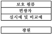
이러한 액정 표시 장치는, 예를 들어 백라이트 광원 상에, 관찰자 측과 백라이트 광원 측에 한 쌍의 편광판이, 액정 셀을 사이에 두고 크로스니콜의 관계로 되도록 배치된 구성이 알려져 있다. In such a liquid crystal display device, for example, a configuration is known in which a pair of polarizers are arranged on the observer side and the backlight light source side on a back light source so that the liquid crystal cell is interposed therebetween in the cross-Nicol relationship.
그리고, 이와 같은 구성의 액정 표시 장치는, 백라이트 광원으로부터 조사된 광이, 백라이트 광원 측의 편광판, 액정 셀 및 관찰자 측의 편광판을 투과하여 표시 화면에서 영상이 표시된다. In the liquid crystal display device having such a constitution, the light irradiated from the backlight light source transmits the polarizing plate on the side of the backlight light source, the liquid crystal cell and the polarizing plate on the observer side, and the image is displayed on the display screen.
통상, 상기 편광판으로서는, 편광자와 광 투과성 기재가 적층된 구조를 갖고, 상기 편광판의 광 투과성 기재로서는, 트리아세틸셀룰로오스로 대표되는 셀룰로오스에스테르를 포함하는 필름이 사용되고 있다(예를 들어, 특허문헌 1 참조). 이것은, 셀룰로오스에스테르는 투명성, 광학 등방성이 우수하고, 면 내에 거의 위상차를 갖지 않기 때문에(리타데이션값이 낮음), 입사 직선 편광의 진동 방향을 변화시키는 일이 매우 적고, 액정 표시 장치의 표시 품질에의 영향이 적기도 하고, 적당한 투수성을 갖기 때문에, 편광판을 제조했을 때에 편광자에 잔류한 수분을 광학 적층체를 통해서 건조시킬 수 있는 등의 이점에 기초하는 것이다.Usually, the polarizing plate has a structure in which a polarizer and a light-transmitting substrate are laminated, and as the light-transmitting substrate of the polarizing plate, a film containing cellulose ester represented by triacetylcellulose is used (see, for example, Patent Document 1 ). This is because the cellulose ester has excellent transparency and optical isotropy and has almost no retardation in the plane (retardation value is low), so that it is very rare to change the vibration direction of the incident linearly polarized light and the display quality of the liquid crystal display And has moisture permeability. Therefore, it is based on the advantage that the moisture remaining in the polarizer can be dried through the optical laminate when the polarizer is manufactured.
그러나, 셀룰로오스에스테르 필름은, 투습도가 너무 높기 때문에, 내습 시험을 행하면 퇴색에 의한 편광도의 저하를 초래하는 등의 문제가 있었다. 이러한 셀룰로오스에스테르 필름의 문제점 때문에 투명성, 내열성, 기계 강도가 우수하고, 또한, 셀룰로오스에스테르 필름에 비하여 저렴하고 시장에서 입수가 용이한, 혹은 간이한 방법으로 제조하는 것이 가능한 범용성 필름을 보호 필름으로서 사용하는 것이 요망되고 있고, 예를 들어 셀룰로오스에스테르 필름 대신, 폴리에틸렌테레프탈레이트 등의 폴리에스테르 필름을 이용하는 시도가 이루어지고 있다(예를 들어, 특허문헌 2 참조). However, since the cellulose ester film has a too high moisture permeability, there has been a problem that if the humidity resistance test is performed, the polarization degree due to discoloration is lowered. A universal film which is excellent in transparency, heat resistance and mechanical strength because of the problems of such a cellulose ester film, is low in cost as compared with the cellulose ester film, is easily available on the market, or can be produced by a simple method is used as a protective film And an attempt has been made to use a polyester film such as polyethylene terephthalate instead of, for example, a cellulose ester film (see, for example, Patent Document 2).
그런데, 이와 같은 구성의 액정 표시 장치에 있어서, 백라이트 광원으로부터 조사된 광을 효율적으로 표시 화면까지 투과시키는 것은, 표시 화면의 휘도 향상에 중요하다. 특히, 최근 급속하게 보급되고 있는 스마트폰 등의 모바일 기기에서는, 배터리의 지속 시간에 직접 영향을 미치기 때문에, 더 효율적으로 백라이트 광원으로부터의 광을 표시 화면까지 투과시키는 것이 요구되고 있다. In the liquid crystal display device having such a configuration, it is important to efficiently transmit the light emitted from the backlight source to the display screen in order to improve the luminance of the display screen. Particularly, in a mobile device such as a smart phone, which is rapidly spreading in recent years, it has a direct influence on the duration of a battery, and therefore, it is required to more efficiently transmit light from a backlight source to a display screen.
이러한 액정 표시 장치로서, 예를 들어 백라이트 광원과 해당 백라이트 광원 측의 편광판 사이에, 편광 분리 필름을 설치하거나 하여 백라이트 광원 측의 편광판에 편광된 광을 입사시키고, 표시 화면의 휘도를 향상시킨 것이 알려져 있다. 또한, 상기 편광 분리 필름이란, 특정한 편광 성분을 투과시킴과 함께, 기타 편광 성분을 반사해서 백라이트 광원 측으로 되돌리는 기능을 갖는 필름이다. As such a liquid crystal display device, for example, it has been known that a polarized light separating film is provided between a backlight light source and a polarizing plate on the backlight light source side, and polarized light is incident on a polarizing plate on the backlight light source side to improve the brightness of the display screen have. The polarized light separating film is a film having a function of transmitting a specific polarized light component and reflecting other polarized light components back to the backlight light source side.
그런데, 이와 같은 구성의 액정 표시 장치의 백라이트 광원 측의 편광판으로서, 폴리에스테르 필름을 포함하는 보호 필름을 사용한 편광판을 사용한 경우, 투과율이 저하되어 버리는 경우가 있었다. 이것은, 폴리에스테르 필름은, 분자쇄 중에 분극률이 큰 방향족환을 갖기 때문에, 고유 복굴절이 매우 크고, 우수한 투명성, 내열성, 기계 강도를 부여하기 위한 연신 처리에 의한 분자쇄의 배향에 수반하여 복굴절이 발현되기 쉽다는 성질을 갖기 때문이다. Incidentally, when a polarizing plate using a protective film containing a polyester film is used as the polarizing plate on the backlight source side of the liquid crystal display device having such a constitution, the transmittance may be lowered. This is because the polyester film has a very large intrinsic birefringence and an excellent birefringence accompanied with the orientation of the molecular chains by the stretching treatment for imparting excellent transparency, heat resistance and mechanical strength, because the polyester film has an aromatic ring having a high polarizability in the molecular chain It is easy to be expressed.
이로 인해, 이러한 폴리에스테르 필름과 같은 면 내에 복굴절률을 갖는 광 투과성 기재를 사용한 편광판을, 액정 표시 장치의 백라이트측의 편광판으로서 사용한 경우, 편광 분리 필름을 통과한 특정한 편광 성분의 편광 상태를 변화시켜 버리기 때문에, 투과율이 저하되어 버리는 경우가 있었다.Therefore, when a polarizing plate using a light-transmitting base material having a birefringence index in the same plane as the polyester film is used as a polarizing plate on the backlight side of a liquid crystal display device, the polarization state of a specific polarizing component passing through the polarized light separating film is changed The transmittance is sometimes lowered.
본 발명은, 상기 현 상황을 감안하여 면 내에 복굴절률을 갖는 광 투과성 기재가 사용된 경우라도, 광 투과율이 우수한 편광판, 해당 편광판의 제조 방법, 화상 표시 장치, 화상 표시 장치의 제조 방법 및 편광판의 광 투과율 개선 방법을 제공하는 것을 목적으로 한다.It is an object of the present invention to provide a polarizing plate having excellent light transmittance, a method for producing the polarizing plate, an image display apparatus, a method for manufacturing an image display apparatus, and a polarizing plate having a birefringent index, even when a light- And a method for improving the light transmittance.
본 발명은, 백라이트 광원 측으로부터, 적어도, 면 내에 복굴절률을 갖는 광 투과성 기재와 편광자가 이 순서대로 적층되고, 화상 표시 장치의 상기 백라이트 광원 측에 배치해서 사용되는 편광판이며, 상기 면 내에 복굴절률을 갖는 광 투과성 기재에, 편광된 광이 입사되는 것이며, 상기 면 내에 복굴절률을 갖는 광 투과성 기재와 상기 편광자는, 상기 면 내에 복굴절률을 갖는 광 투과성 기재의 굴절률이 작은 방향인 진상축과 상기 편광자의 투과축이 이루는 각도가, 0°±30° 또는 90°±30°로 되도록 적층되어 있는 것을 특징으로 하는 편광판이다. The present invention is a polarizing plate that is laminated in this order on a light transmitting base material having a birefringent index in a plane and a polarizer in this order from the backlight source side and is used for disposition on the backlight source side of the image display device, Transmitting substrate having a birefringent index in the plane and the polarizer are arranged such that a phase difference between a fast axis which is a direction in which a refractive index of a light transmitting base material having a birefringence in the plane is small, And the angle formed by the transmission axis of the polarizer is 0 占 30 占 or 90 占 30 占.
본 발명의 편광판에 있어서, 상기 면 내에 복굴절률을 갖는 광 투과성 기재와 상기 편광자는, 상기 면 내에 복굴절률을 갖는 광 투과성 기재의 굴절률이 작은 방향인 진상축과 상기 편광자의 투과축이 이루는 각도가, 0°±15° 또는 90°±15°로 되도록 적층되어 있는 것이 바람직하다. In the polarizing plate of the present invention, the light transmitting base material having the birefringent index in the plane and the polarizer are preferably such that the angle formed by the fast axis which is the direction in which the refractive index of the light transmitting base material having the birefringent index in the plane is small and the transmission axis of the polarizer is , 0 ° ± 15 °, or 90 ° ± 15 °.
또한, 상기 면 내에 복굴절률을 갖는 광 투과성 기재는, 굴절률이 큰 방향인 지상축 방향의 굴절률(nx)과, 상기 지상축 방향과 직교하는 방향인 진상축 방향의 굴절률(ny)의 차(nx-ny)가, 0.01 이상인 것이 바람직하다. The light transmitting base material having a birefringent index in the plane has a refractive index difference between the refractive index nx in the direction of the slow axis and the refractive index ny in the direction of the fast axis perpendicular to the direction of the slow axis, -ny) is preferably 0.01 or more.
또한, 상기 면 내에 복굴절률을 갖는 광 투과성 기재의 굴절률이 큰 방향인 지상축 방향의 굴절률(nx)과, 상기 지상축 방향과 직교하는 방향인 진상축 방향의 굴절률(ny)과, 상기 광 투과성 기재의 평균 굴절률(N)이, 하기 식의 관계를 갖고, 또한, 상기 진상축과 편광자의 투과축이 이루는 각도가 0°±2°인 것이 바람직하다. The refractive index (nx) in the slow axis direction, which is the direction in which the refractive index of the light-transmitting substrate having the birefringence in the plane is large, the refractive index (ny), in the fast axis direction in the direction orthogonal to the slow axis direction, It is preferable that the average refractive index (N) of the base material has a relationship represented by the following formula and the angle formed by the fast axis and the transmission axis of the polarizer is 0 占 占 占.
nx>N>ny nx> n> ny
또한, 본 발명은, 적어도, 면 내에 복굴절률을 갖는 광 투과성 기재와 편광자가 이 순서대로 적층되고, 화상 표시 장치의 백라이트 광원 측에 배치해서 사용되는 편광판의 제조 방법이며, 상기 면 내에 복굴절률을 갖는 광 투과성 기재와 상기 편광자를, 상기 면 내에 복굴절률을 갖는 광 투과성 기재의 굴절률이 작은 방향인 진상축과 상기 편광자의 투과축이 이루는 각도가, 0°±30° 또는 90°±30°로 되도록 적층하는 공정을 갖는 것을 특징으로 하는 편광판의 제조 방법이기도 하다. The present invention also provides a method for producing a polarizing plate in which at least a light transmitting base material having a birefringent index in a plane and a polarizer are stacked in this order and arranged on the backlight source side of an image display apparatus, And the polarizer are arranged such that an angle formed by a fast axis in a direction in which the refractive index of the light transmitting base material having a birefringent index in the plane is small and a transmission axis of the polarizer is 0 占 30 占 or 90 占 30 And then laminating the polarizing plate in such a manner as to cover the polarizing plate.
또한, 본 발명은, 상술한 본 발명의 편광판을 구비하는 것을 특징으로 하는 화상 표시 장치이기도 하다. Further, the present invention is also an image display device comprising the above-mentioned polarizing plate of the present invention.
본 발명의 화상 표시 장치는, 백라이트 광원과 면 내에 복굴절률을 갖는 광 투과성 기재 사이에, 편광 분리 필름을 갖는 것이 바람직하다. The image display device of the present invention preferably has a polarized light separating film between a backlight light source and a light transmitting base material having a birefringence in the plane.
또한, 본 발명의 화상 표시 장치는, 관찰자 측에 적어도 면 내에 복굴절률을 갖는 상부 광 투과성 기재가 상부 편광자 상에 설치된 상부 편광판을 더 갖고, 상기 면 내에 복굴절률을 갖는 상부 광 투과성 기재와 상기 상부 편광자는, 상기 면 내에 복굴절률을 갖는 상부 광 투과성 기재의 굴절률이 작은 방향인 진상축과, 상기 상부 편광자의 투과축이 이루는 각도가 90°로 되지 않도록 배치되어 있는 것이 바람직하다. The image display apparatus of the present invention further includes an upper polarizing plate provided on the observer side with an upper light-transmitting base material having a birefringence index at least in a plane on the upper polarizer, and an upper light- It is preferable that the polarizer is arranged such that the angle formed by the fast axis which is the direction in which the refractive index of the upper light transmitting base material having the birefringence in the plane is small and the transmission axis of the upper polarizer is not 90 degrees.
또한, 본 발명은, 적어도, 면 내에 복굴절률을 갖는 광 투과성 기재와 편광자가 이 순서대로 적층되고, 화상 표시 장치의 백라이트 광원 측에 배치해서 사용되는 편광판을 구비한 화상 표시 장치의 제조 방법이며, 상기 면 내에 복굴절률을 갖는 광 투과성 기재와 상기 편광자를, 상기 면 내에 복굴절률을 갖는 광 투과성 기재의 굴절률이 작은 방향인 진상축과 상기 편광자의 투과축이 이루는 각도가, 0°±30° 또는 90°±30°로 되도록 적층하는 공정을 갖는 것을 특징으로 하는 화상 표시 장치의 제조 방법이기도 하다. The present invention also relates to a method of manufacturing an image display apparatus including a polarizing plate at least including a light transmitting base material having a birefringent index in a plane and a polarizer stacked in this order and arranged on a backlight source side of an image display apparatus, An angle formed by a transmission axis of the polarizer and a fast axis which is a direction in which a refractive index of a light transmitting base material having a birefringent index in the plane is small is 0 占 30 占 or And 90 占 占 30 占.
또한, 본 발명은, 적어도, 면 내에 복굴절률을 갖는 광 투과성 기재와 편광자가 이 순서대로 적층되고, 화상 표시 장치의 백라이트 광원 측에 배치해서 사용되는 편광판의 광 투과율 개선 방법이며, 상기 면 내에 복굴절률을 갖는 광 투과성 기재와 상기 편광자를, 상기 면 내에 복굴절률을 갖는 광 투과성 기재의 굴절률이 작은 방향인 진상축과 상기 편광자의 투과축이 이루는 각도가, 0°±30° 또는 90°±30°로 되도록 적층하는 것을 특징으로 하는 편광판의 광 투과율 개선 방법이기도 하다. Further, the present invention is a method for improving the light transmittance of a polarizing plate, which is used at least on a backlight light source side of an image display apparatus in which a light transmitting base material having a birefringent index in a plane and a polarizer are stacked in this order, Wherein the angle formed by the transmission axis of the polarizer and the fast axis which is the direction in which the refractive index of the light transmitting base material having the birefringent index in the plane is smaller is 0 占 30 占 or 90 占 30 Deg.], And the light transmittance of the polarizing plate is improved.
이하에, 본 발명을 상세하게 설명한다. Hereinafter, the present invention will be described in detail.
또한, 본 발명에서는, 특별한 기재가 없는 한, 단량체, 올리고머, 예비 중합체 등의 경화성 수지 전구체도 “수지”라고 기재한다. In the present invention, unless otherwise specified, the curable resin precursor such as a monomer, oligomer, prepolymer, etc. is also referred to as " resin ".
본 발명자들은, 광 투과성 기재와 편광자가 적층되고, 화상 표시 장치의 백라이트 광원 측에 배치해서 사용됨과 함께, 편광된 광이 입사되는 편광판에 대해서 예의 검토한 결과, 면 내에 복굴절률을 갖는 광 투과성 기재를 사용한 경우, 편광판의 광 투과율에는, 해당 광 투과성 기재의 굴절률이 작은 방향인 진상축과 편광자의 투과축 사이에서 각도 의존성이 있음을 알아내었다. The inventors of the present invention have made intensive studies on a polarizing plate in which a light-transmitting base material and a polarizer are stacked and arranged on the backlight source side of an image display apparatus and on which polarized light is incident. As a result, It was found that the light transmittance of the polarizing plate had an angle dependence between the fast axis which is a direction in which the refractive index of the light transmitting base material is small and the transmission axis of the polarizer.
즉, 본 발명자들은, 면 내에 복굴절률을 갖는 광 투과성 기재의 굴절률이 작은 방향인 진상축과 상기 편광자의 투과축이 특정한 각도 범위로 되도록 적층함으로써, 해당 편광판의 광 투과율을 향상시킬 수 있음을 알아내었다. 그리고, 이러한 지견에 기초하여 본 발명자들은, 또한 예의 검토한 결과, 종래 광학 등방성 재료로서 사용되어 온 셀룰로오스에스테르 등의 재료를 포함하는 광 투과성 기재에 대하여도, 굳이 복굴절률을 갖게 한 광 투과성 기재로 함으로써, 광학 등방성 재료인 채 사용하는 것 보다도, 광 투과율을 향상시킬 수 있음을 알아내고, 본 발명을 완성하기에 이르렀다. That is, the inventors of the present invention know that the light transmittance of the polarizing plate can be improved by laminating the light-transmitting base having a birefringent index in the plane so that the refractive index of the polarizing axis of the polarizing element is in a specific angle range I got it. Based on these findings, the present inventors have also made intensive investigations and, as a result, have found that even for a light-transmitting substrate including a material such as cellulose ester conventionally used as an optically isotropic material, a light- The present inventors have found that the optical transmittance can be improved as compared with the case where the optically isotropic material is used as the optically isotropic material, and thus the present invention has been accomplished.
본 발명의 편광판은, 적어도, 면 내에 복굴절률을 갖는 광 투과성 기재와 편광자가 이 순서대로 적층되고, 화상 표시 장치의 백라이트 광원 측에 배치해서 사용되는 것이다. The polarizing plate of the present invention is at least a light transmitting base material having a birefringent index in a plane and a polarizer are stacked in this order and arranged on the backlight source side of the image display apparatus.
상기 광 투과성 기재로서는, 면 내에 복굴절률을 갖는 것이라면 특별히 한정되지 않고, 예를 들어, 폴리카르보네이트, 아크릴, 폴리에스테르 등을 포함하는 기재를 들 수 있지만, 그 중에서도, 비용 및 기계적 강도에 있어서 유리한 폴리에스테르 기재인 것이 적합하다. 또한, 이하의 설명에서는, 면 내에 복굴절률을 갖는 광 투과성 기재를 폴리에스테르 기재로서 설명한다. The light-transmitting base material is not particularly limited as long as it has a birefringent index in a plane. For example, a base material including polycarbonate, acrylic, polyester and the like can be mentioned. Among them, in terms of cost and mechanical strength Favorable polyester substrates are suitable. In the following description, a light-transmitting base material having a birefringence in a plane will be described as a polyester base material.
또한, 본 발명의 편광판에 있어서, 상기 광 투과성 기재로서는, 종래 광학 등방성 재료로서 사용된 셀룰로오스에스테르 등을 포함하는 광 투과성 기재이어도, 굳이 복굴절률을 갖게 함으로써 사용할 수 있다. In the polarizing plate of the present invention, as the light-transmitting base material, a light-transmitting base material including a cellulose ester or the like conventionally used as an optically isotropic material can be used by having a birefringence.
본 발명의 편광판에 있어서, 상기 폴리에스테르 기재의 면 내에 있어서 굴절률이 큰 방향(지상축 방향)의 굴절률(nx)과, 상기 지상축 방향과 직교하는 방향(진상축 방향)의 굴절률(ny)의 차 nx-ny(이하, Δn이라고도 표기함)는 0.01 이상인 것이 바람직하다. 상기 Δn이 0.01 미만이면 투과율 향상 효과가 적어지는 경우가 있다. 한편, 상기 Δn은, 0.30 이하인 것이 바람직하다. 0.30을 초과하면, 폴리에스테르 기재를 과도하게 연신할 필요가 발생하기 때문에, 폴리에스테르 기재의 터짐, 찢어짐 등이 발생하기 쉬워져, 공업 재료로서의 실용성이 현저하게 저하하는 경우가 있다. In the polarizing plate of the present invention, the refractive index (nx) in the direction of the large refractive index (geoglass axis direction) and the refractive index (ny) in the direction perpendicular to the geoglass axis direction The difference nx-ny (hereinafter also referred to as? N) is preferably 0.01 or more. If? N is less than 0.01, the transmittance improving effect may be reduced. On the other hand, the above-mentioned? N is preferably 0.30 or less. If it is more than 0.30, it is necessary to excessively stretch the polyester base material, so that the polyester base material tends to easily burst and tear, and practical utility as an industrial material may be remarkably lowered.
이상의 관점에서, 상기 Δn의 보다 바람직한 하한은 0.05, 더 바람직한 상한은 0.27이다. 또한, 상기 Δn이 0.27을 초과하면, 내습 열성 시험에서의 폴리에스테르 기재의 내구성이 떨어지는 경우가 있다. 내습 열성 시험에서의 내구성이 우수한 점에서, 상기 Δn의 더욱 바람직한 상한은 0.25이다. 이러한 Δn을 만족함으로써, 적합한 광 투과율의 향상을 도모할 수 있다. From the above viewpoint, a more preferable lower limit of the above-mentioned? N is 0.05, and a more preferable upper limit is 0.27. Further, when? N exceeds 0.27, the durability of the polyester base in the heat and humidity resistance test may be deteriorated. In view of the excellent durability in the humid heat resistance test, the more preferable upper limit of? N is 0.25. By satisfying this? N, an appropriate light transmittance can be improved.
또한, 본 명세서에 있어서, 광 투과성 기재가 면 내에 복굴절률을 갖고 있는지 여부는, 파장 550nm의 굴절률에 있어서 Δn(nx-ny)≥0.0005인 것은 복굴절성을 갖고 있는 것으로 하고, Δn <0.0005인 것은 복굴절성을 갖고 있지 않는 것으로 한다. 복굴절률은, 오지 게이소꾸 기끼사제 KOBRA-WR을 사용하여, 측정 각 0° 또한 측정 파장 552.1nm에서 설정하여 측정을 행할 수 있다. 이때, 복굴절률 산출에는, 막 두께, 평균 굴절률이 필요하게 된다. 막 두께는, 예를 들어 마이크로미터(Digimatic Micrometer, 미쯔토요사제)나, 전기 마이크로미터(안리쓰사제)를 사용하여 측정할 수 있다. 평균 굴절률은 아베 굴절률계나, 엘립소미터를 사용하여 측정할 수 있다. In this specification, whether or not the light-transmitting base material has a birefringent index in a plane indicates that birefringence is obtained when Δn (nx-ny) ≥0.0005 is satisfied at a refractive index of 550 nm and Δn <0.0005 And does not have birefringence. The birefringence index can be measured by using KOBRA-WR manufactured by Oji Keisei Kikuchi at a measurement angle of 0 ° and a measurement wavelength of 552.1 nm. At this time, the film thickness and the average refractive index are required for the calculation of the birefringence. The film thickness can be measured using, for example, a micrometer (Digimatic Micrometer, manufactured by Mitsutoyo Corporation) or an electric micrometer (manufactured by Anritsu Corporation). The average refractive index can be measured using an Abbe's refractometer or an ellipsometer.
또한, 일반적으로 등방성 재료로서 알려진, 트리아세틸셀룰로오스를 포함하는 TD80UL-M(후지 필름사제), 시클로올레핀 중합체를 포함하는 ZF16-100(니혼 제온사제)의 Δn은, 상기 측정 방법에 의해, 각각 0.0000375, 0.00005이며, 복굴절성을 갖고 있지 않다고(등방성) 판단했다. Further,? N of ZF16-100 (manufactured by Nippon Zeon Co., Ltd.) containing TD80UL-M (manufactured by Fuji Photo Film Co., Ltd.) containing triacetyl cellulose and cycloolefin polymer, which is generally known as an isotropic material, is 0.0000375 , 0.00005, and it was judged that it is not birefringent (isotropic).
기타, 복굴절률을 측정하는 방법으로서, 2매의 편광판을 사용하여, 광 투과성 기재의 배향축 방향(주축의 방향)을 구하고, 배향축 방향에 대하여 직교하는 2개의 축 굴절률(nx, ny)을, 아베 굴절률계(아타고사제 NAR-4T)에 의해 구할 수도 있고, 이면에 흑색 비닐 테이프(예를 들어, 야마토 비닐 테이프 No200-38-2138mm 폭)를 붙이고 나서, 분광 광도계(V7100형, 자동 절대 반사율 측정 유닛, VAR-7010 니혼 분꼬우사제)를 사용하여, 편광 측정:S 편광으로, S 편광에 대하여, 지상축을 평행으로 한 경우와, 진상축을 평행으로 한 경우의 5도 반사율을 측정하고, 반사율(R)과 굴절률(n)의 관계를 나타내는 하기 식(1)으로부터 지상축과 진상축의 각 파장의 굴절률(nx, ny)을 산출할 수도 있다.As another method for measuring the birefringence index, two polarizing plates are used to obtain the orientation axis direction (principal axis direction) of the light-transmitting base material and two axis refractive indexes (nx, ny) perpendicular to the orientation axis direction as , A black vinyl tape (for example, Yamato Vinyl Tape No. 200-38-2138 mm wide) is attached to the back surface, and a spectrophotometer (V7100 type, automatic absolute reflectance 5-degree reflectance was measured in the case where the slow axis was parallel to the S-polarized light and the slow axis was parallel to the S-polarized light, and the reflectance was measured using the measurement unit, VAR-7010 made by Nihon Bunko Co., (Nx, ny) of the respective wavelengths of the slow axis and the fast axis can be calculated from the following equation (1) showing the relationship between the refractive index (R) and the refractive index (n).
R(%)=(1-n)2/(1+n)2 식(1) R (%) = (1- n) 2 / (1 + n) 2 Formula (1)
또한, 평균 굴절률은, 아베 굴절률계나, 엘립소미터를 사용하여 측정할 수 있고, 광 투과성 필름의 두께 방향의 굴절률 nz는, 상기의 방법에 의해 측정한, nx, ny를 사용하여 하기 식(2)로부터 계산할 수 있다. The average refractive index can be measured using an Abbe's refractometer or an ellipsometer, and the refractive index nz in the thickness direction of the light-transmitting film can be measured by the following equation (2) using nx and ny, ).
평균 굴절률 N=(nx+ny+nz)/3 식(2) Average refractive index N = (nx + ny + nz) / 3 (2)
여기서, nx, ny, nz의 산출 방법을 구체예를 들어 설명한다. Here, a calculation method of nx, ny, and nz will be described with specific examples.
또한, nx는 광 투과성 기재의 지상축 방향의 굴절률, ny는 광 투과성 기재의 진상축 방향의 굴절률, nz는 광 투과성 기재의 두께 방향의 굴절률이다. Nx is the refractive index in the slow axis direction of the light-transmitting substrate, ny is the refractive index in the fast axis direction of the light-transmitting substrate, and nz is the refractive index in the thickness direction of the light-
(3차원 굴절률 파장 분산의 산출) (Calculation of three-dimensional refractive index wavelength dispersion)
우선은, 시클로올레핀 중합체를 예를 들어, 3차원 굴절률 파장 분산의 산출 방법을 구체적으로 설명한다. First, the method of calculating the three-dimensional refractive index wavelength dispersion, for example, of the cycloolefin polymer will be described in detail.
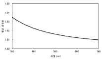
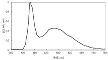
면 내에 복굴절률을 갖지 않는 시클로올레핀 중합체 필름의 평균 굴절률 파장 분산을, 엘립소미터(UVISEL 호리바 세이사꾸쇼)를 사용하여 측정하고, 그 결과를 도 1에 도시했다. 이 측정 결과로부터, 면 내에 복굴절률을 갖지 않는 시클로올레핀 중합체 필름의 평균 굴절률 파장 분산을, nx와 ny, nz의 굴절률 파장 분산으로 했다. The average refractive index wavelength dispersion of the cycloolefin polymer film having no birefringence in the plane was measured using an ellipsometer (UVISEL Horiba Seisakusho). The results are shown in Fig. From the measurement results, the average refractive index wavelength dispersion of the cycloolefin polymer film having no birefringence in the plane was defined as nx and ny, and the refractive index wavelength dispersion of nz.
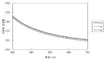
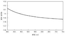
이 필름을 연신 온도 155℃에서 자유단 1축 연신하여 면 내에 복굴절률을 갖는 필름을 얻었다. 막 두께는 100㎛이었다. 이 자유단 1축 연신한 필름을, 복굴절 측정계(KOBRA-21ADH, 오지 게이소꾸 기끼)에 의해, 입사각 0° 및 40°의 리타데이션값을 4 파장(447.6nm, 547.0nm, 630.6nm, 743.4nm)에서 측정했다. This film was uniaxially stretched at a stretching temperature of 155 ° C to obtain a film having a birefringence in the plane. The film thickness was 100 mu m. This free-uniaxially stretched film was irradiated with four wavelengths (447.6 nm, 547.0 nm, 630.6 nm, and 743.4 nm) by a birefringence meter (KOBRA-21ADH, Oji Keisei) ).
각 파장에서의, 평균 굴절률(N)과 리타데이션값을 바탕으로, 복굴절 측정계 부속의 3차원 파장 분산 계산 소프트웨어를 사용하여, Cauchy 또는 Sellmeier의 식 등을 사용하여, 3차원 굴절률 파장 분산을 산출하고, 그 결과를 도 2에 도시했다. 또한, 도 2 중, ny는 nz와 거의 겹쳐서 나타나 있다. 이 결과로부터, 면 내에 복굴절률을 갖는 시클로올레핀 중합체 필름의 3차원 굴절률 파장 분산을 얻었다. Based on the average refractive index (N) and the retardation value at each wavelength, the three-dimensional refractive index wavelength dispersion is calculated using the Cauchy or Sellmeier equation using the three-dimensional wavelength dispersion calculation software attached to the birefringence meter , And the results are shown in Fig. 2, ny is almost overlapped with nz. From this result, a three-dimensional refractive index wavelength dispersion of a cycloolefin polymer film having a birefringence in a plane was obtained.
(분광 광도계를 사용한 굴절률 nx, ny, nz의 산출) (Calculation of refractive indices nx, ny and nz using a spectrophotometer)
폴리에틸렌테레프탈레이트를 예를 들어, 분광 광도계를 사용한 굴절률 nx, ny, nz의 산출 방법을 구체적으로 설명한다.A method of calculating the refractive indices nx, ny, and nz using a spectrophotometer, for example, polyethylene terephthalate will be described in detail.
면 내에 복굴절률을 갖지 않는 폴리에틸렌테레프탈레이트의 평균 굴절률 파장 분산은, 상기 3차원 굴절률 파장 분산의 산출 방법과 마찬가지로 행하였다. The average refractive index wavelength dispersion of the polyethylene terephthalate having no birefringence in the plane was performed in the same manner as the above-mentioned calculation method of the three-dimensional refractive index wavelength dispersion.
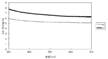
면 내에 복굴절률을 갖는 폴리에틸렌테레프탈레이트의 굴절률 파장 분산(nx, ny)은, 분광 광도계(V7100형, 자동 절대 반사율 측정 유닛 VAR-7010 니혼 분꼬우사제)를 사용해서 산출했다. 측정면과는 반대면에, 이면 반사를 방지하기 위해서 측정 스폿 면적보다 큰 폭의 흑색 비닐 테이프(예를 들어, 야마토 비닐 테이프 No200-38-21 38mm 폭)을 붙이고 나서, 편광 측정:S 편광으로, 광 투과성 기재의 배향축을 평행하게 설치한 경우와, 배향축에 대하여 직교하는 축을 평행하게 설치한 경우의 5도 분광 반사율을 측정했다. 결과를 도 3에 도시한다. 반사율(R)과 굴절률(n)의 관계를 나타내는 상기 식(1)에서 굴절률 파장 분산(nx, ny)을 산출했다. 더 큰 반사율(상기 식(1)에 의해 산출된 굴절률)을 나타내는 방향을 nx(지상축이라고도 함)라 하고, 보다 작은 반사율(상기 식(1)에 의해 산출된 굴절률)을 나타내는 방향을 ny(진상축이라고도 함)라고 했다. 여기서, 배향축이란, 광원 위에 크로스니콜 상태로 설치된 2매의 편광판 사이에, 면 내에 복굴절률을 갖는 필름을 끼우고, 필름을 회전시켜 광 누설이 가장 적은 상태일 때, 편광판의 투과축, 또는 흡수축과 동일한 방향을 필름의 배향축으로 할 수 있다. 또한, 굴절률 nz는 상기 평균 굴절률(N)과 상기 식(2)에 의해 산출할 수 있다. The refractive index wavelength dispersion (nx, ny) of the polyethylene terephthalate having a birefringence in the plane was calculated by using a spectrophotometer (V7100 type, automatic absolute reflectance measuring unit VAR-7010 manufactured by Nippon Bunko Co., Ltd.). A black vinyl tape (for example, Yamato vinyl tape No. 200-38-21 38 mm wide) having a width larger than the measurement spot area was attached on the opposite side of the measurement side to prevent reflection on the back side, and then polarizing measurement: S polarized light , The 5-degree spectral reflectance was measured in the case where the alignment axis of the light-transmitting substrate was provided in parallel and in the case where axes perpendicular to the alignment axis were provided in parallel. The results are shown in Fig. The refractive index wavelength dispersion (nx, ny) was calculated from the above formula (1) showing the relationship between the reflectance R and the refractive index n. The direction indicating the larger reflectance (the refractive index calculated by the above formula (1)) is referred to as nx (also referred to as the slow axis) and the direction representing the smaller reflectance (refractive index calculated by the above formula (1) Also known as the axis of truth). Here, the orientation axis refers to a state in which a film having a birefringence index is sandwiched between two polarizing plates provided in a Cross-Nicol state on a light source, and when the film is rotated to minimize light leakage, The same direction as the absorption axis can be used as the orientation axis of the film. The refractive index nz can be calculated from the average refractive index (N) and the above formula (2).
상기 폴리에스테르 기재를 구성하는 재료로서는, 상술한 Δn을 충족하는 것이면 특별히 한정되지 않지만, 방향족 이염기산 또는 그 에스테르 형성성 유도체와 디올 또는 그 에스테르 형성성 유도체로부터 합성되는 선상 포화 폴리에스테르를 들 수 있다. 이와 같은 폴리에스테르의 구체예로서, 폴리에틸렌테레프탈레이트, 폴리에틸렌이소프탈레이트, 폴리부틸렌테레프탈레이트, 폴리(1,4-시클로헥실렌디메틸렌테레프탈레이트), 폴리에틸렌나프탈레이트(폴리에틸렌-2,6-나프탈레이트, 폴리에틸렌-1,4-나프탈레이트, 폴리에틸렌-1,5-나프탈레이트, 폴리에틸렌-2,7-나프탈레이트, 폴리에틸렌-2,3-나프탈레이트) 등을 예시할 수 있다. 또한, 폴리에스테르 기재에 사용되는 폴리에스테르는, 이들 폴리에스테르의 공중합체이어도 되고, 상기 폴리에스테르를 주체(예를 들어 80몰% 이상의 성분)로 하고, 적은 비율(예를 들어 20몰% 이하)의 다른 종류의 수지와 블렌드한 것이어도 된다. 상기 폴리에스테르로서 폴리에틸렌테레프탈레이트 또는 폴리에틸렌나프탈레이트가 역학적 물성이나 광학 물성 등의 밸런스가 양호하므로 특히 바람직하다. 특히, 폴리에틸렌테레프탈레이트(PET)를 포함하는 것이 바람직하다. 폴리에틸렌테레프탈레이트는 범용성이 높고, 입수가 용이하기 때문이다. 본 발명에 있어서는 PET와 같은, 범용성이 매우 높은 필름이어도, 광 투과율이 우수한 편광판을 얻을 수 있다. 또한, PET는 투명성, 열 또는 기계적 특성이 우수하고, 연신 가공에 의해 Δn의 제어가 가능하며, 고유 복굴절이 크기 때문에, 비교적 용이하게 복굴절률을 갖게 할 수 있다. The material constituting the polyester base material is not particularly limited as long as it satisfies the above-mentioned n, but linear saturated polyesters synthesized from an aromatic dibasic acid or an ester-forming derivative thereof and a diol or an ester-forming derivative thereof . Specific examples of such polyesters include polyethylene terephthalate, polyethylene isophthalate, polybutylene terephthalate, poly (1,4-cyclohexylene dimethylene terephthalate), polyethylene naphthalate (polyethylene-2,6-naphthalate , Polyethylene-1,4-naphthalate, polyethylene-1,5-naphthalate, polyethylene-2,7-naphthalate, and polyethylene-2,3-naphthalate). The polyester used in the polyester substrate may be a copolymer of these polyesters, and the polyester may be used as a main component (for example, 80 mol% or more) and a small proportion (for example, 20 mol% or less) Or may be blended with other types of resins. As the polyester, polyethylene terephthalate or polyethylene naphthalate is particularly preferred because of good balance of mechanical properties and optical properties. Particularly, it is preferable to include polyethylene terephthalate (PET). Polyethylene terephthalate is highly versatile and easy to obtain. In the present invention, even a highly general-purpose film, such as PET, can obtain a polarizing plate having excellent light transmittance. Further, PET is excellent in transparency, thermal or mechanical properties, can control the DELTA n by stretching, has a large intrinsic birefringence, and can have a birefringence index relatively easily.
상기 폴리에스테르 기재를 얻는 방법으로서는, 상술한 Δn을 충족하는 방법이면 특별히 한정되지 않지만, 예를 들어 재료의 상기 PET 등의 폴리에스테르를 용융하고, 시트 형상으로 압출 성형된 미연신 폴리에스테르를 유리 전이 온도 이상의 온도에 있어서 텐터 등을 사용해서 가로 연신 후, 열 처리를 실시하는 방법을 들 수 있다. The method of obtaining the polyester base material is not particularly limited as long as the method satisfies the above-mentioned? N. For example, a polyester such as PET as described above is melted and an unstretched polyester extruded into a sheet- A transverse stretching method using a tenter or the like at a temperature equal to or higher than the temperature, and then heat treatment is performed.
상기 가로 연신 온도로서는 80℃ 내지 130℃가 바람직하고, 보다 바람직하게는 90℃ 내지 120℃이다. 또한, 가로 연신 배율은 2.5 내지 6.0배가 바람직하고, 보다 바람직하게는 3.0 내지 5.5배이다. 상기 가로 연신 배율이 6.0배를 초과하면, 얻어지는 폴리에스테르 기재의 투명성이 저하되기 쉬워지고, 가로 연신 배율이 2.5배 미만이면 연신 장력도 작아지기 때문에, 얻어지는 폴리에스테르 기재의 복굴절이 작아지는 경우가 있다. The transverse stretching temperature is preferably 80 ° C to 130 ° C, more preferably 90 ° C to 120 ° C. The transverse stretch magnification is preferably 2.5 to 6.0 times, more preferably 3.0 to 5.5 times. If the transverse stretching magnification exceeds 6.0 times, the transparency of the resulting polyester base tends to be lowered. If the transverse stretching magnification is less than 2.5 times, the stretching tension is also reduced, so that the birefringence of the resulting polyester base may be reduced .
또한, 본 발명에 있어서는, 2축 연신 시험 장치를 사용하여, 상기 미연신 폴리에스테르의 가로 연신을 상기 조건에서 행한 후, 해당 가로 연신에 대한 흐름 방향의 연신(이하, 세로 연신이라고도 함)을 행해도 된다. 이 경우, 상기 세로 연신은, 연신 배율이 2배 이하인 것이 바람직하다. 상기 세로 연신의 연신 배율이 2배를 초과하면, Δn의 값을 상술한 바람직한 범위로 할 수 없는 경우가 있다. Further, in the present invention, the transverse stretching of the unstretched polyester is performed under the above conditions using a biaxial stretching tester, and then stretching in the flow direction (hereinafter also referred to as longitudinal stretching) to the transverse stretching is performed . In this case, it is preferable that the longitudinal stretching is two times or less the stretching magnification. If the elongation magnification of the longitudinal stretching exceeds 2 times, the value of? N may not be within the preferable range described above.
또한, 상기 열 처리 시의 처리 온도로서는 100℃ 내지 250℃가 바람직하고, 보다 바람직하게는 180℃ 내지 245℃이다. The treatment temperature during the heat treatment is preferably 100 占 폚 to 250 占 폚, and more preferably 180 占 폚 to 245 占 폚.
상기 폴리에스테르 기재의 두께로서는, 5 내지 300㎛의 범위 내인 것이 바람직하다. 5㎛ 미만이면 터짐, 찢어짐 등이 발생하기 쉬워져 공업 재료로서의 실용성이 현저하게 저하되는 경우가 있다. 한편, 300㎛를 초과하면, 폴리에스테르 기재가 매우 강직하고, 고분자 필름 특유의 유연함이 저하되어 역시 공업 재료로서의 실용성이 저하되므로 바람직하지 않다. 상기 폴리에스테르 기재의 두께의 보다 바람직한 하한은 10㎛, 더 바람직한 상한은 200㎛이며, 더욱 바람직한 상한은 150㎛이다. The thickness of the polyester base material is preferably in the range of 5 to 300 mu m. If it is less than 5 탆, breakage or tearing easily occurs, and practical utility as an industrial material may be remarkably lowered. On the other hand, if it exceeds 300 탆, the polyester substrate is very rigid, and the flexibility inherent to the polymer film is deteriorated and the practicality as an industrial material is lowered, which is not preferable. A more preferable lower limit of the thickness of the polyester base material is 10 mu m, a more preferable upper limit is 200 mu m, and a more preferable upper limit is 150 mu m.
또한, 상기 폴리에스테르 기재는, 가시광 영역에서의 투과율이 80% 이상인 것이 바람직하고, 84% 이상인 것이 보다 바람직하다. 또한, 상기 투과율은, JIS K7361-1(플라스틱-투명 재료의 전체 광 투과율 시험 방법)에 의해 측정할 수 있다. The polyester base material preferably has a transmittance of 80% or more in the visible light region, and more preferably 84% or more. The transmittance can be measured by JIS K7361-1 (total light transmittance test method of plastic-transparent material).
또한, 본 발명에 있어서, 상기 폴리에스테르 기재에는 본 발명의 취지를 일탈하지 않는 범위에서, 비누화 처리, 글로우 방전 처리, 코로나 방전 처리, 자외선(UV) 처리 및 화염 처리 등의 표면 처리를 행해도 된다. In the present invention, the polyester substrate may be subjected to surface treatment such as saponification treatment, glow discharge treatment, corona discharge treatment, ultraviolet (UV) treatment and flame treatment within the scope of the present invention .
상기 편광자로서는 특별히 한정되지 않고, 예를 들어, 요오드 등에 의해 염색하고, 연신한 폴리비닐알코올 필름, 폴리비닐포르말 필름, 폴리비닐아세탈 필름,에틸렌-아세트산 비닐 공중합체계 비누화 필름 등을 사용할 수 있다. The polarizer is not particularly limited, and for example, a stretched polyvinyl alcohol film, a polyvinyl formal film, a polyvinyl acetal film, an ethylene-vinyl acetate copolymerization system saponified film and the like can be used which are dyed with iodine or the like.
본 발명의 편광판에 있어서, 상기 광 투과성 기재와 상기 편광자는, 상기 광 투과성 기재의 굴절률이 작은 방향인 진상축과 상기 편광자의 투과축이 이루는 각도가, 0°±30° 또는 90°±30°로 되도록 적층되어 있다. 본 발명의 편광판은, 상기 광 투과성 기재와 상기 편광자가 상술한 바와 같이 배치되기 때문에, 상술한 바와 같은 광 투과율을 우수한 것으로 할 수 있다. 즉, 상기 광 투과성 기재의 진상축과 상기 편광자의 투과축이 이루는 각도가 상기 범위를 벗어날 경우, 구체적으로는, 45°±15° 미만인 경우, 본 발명의 편광판 광 투과율이 매우 낮은 것이 된다. 이것은, 이하의 이유에 의한 것이다. In the polarizing plate of the present invention, it is preferable that the light transmitting base and the polarizer have an angle formed by a fast axis which is a direction in which the refractive index of the light transmitting base is small and a transmission axis of the polarizer is 0 ° ± 30 ° or 90 ° ± 30 ° As shown in Fig. In the polarizing plate of the present invention, since the light transmitting base and the polarizer are arranged as described above, the light transmittance as described above can be made excellent. In other words, when the angle between the fast axis of the transparent base and the transmission axis of the polarizer is out of the above range, specifically less than 45 ° ± 15 °, the polarizing plate light transmittance of the present invention becomes extremely low. This is for the following reasons.
광원과 편광 소자 사이에 편광 분리 필름을 구비한 편광판에서는, 통상 편광자의 투과축을 투과하는 광의 편광축의 방향과, 편광 분리 필름을 투과한 편광된 광의 편광축의 방향은 일치하도록 설치되어 있다. 이로 인해, 편광자와 편광 분리 필름 사이에, 면 내에 복굴절률을 갖는 광 투과성 기재가 설치되고, 또한, 상기 광 투과성 기재의 진상축과 상기 편광자의 투과축이 이루는 각도가, 45°±15° 미만의 범위일 경우, 편광 분리 필름을 투과한 편광된 광의 편광축이 변화되어 버리고, 편광자의 흡수축에 의해 흡수되어버려, 편광판의 광 투과율이 매우 낮아져 버린다. In a polarizing plate provided with a polarizing separation film between a light source and a polarizing element, the direction of the polarization axis of the light passing through the transmission axis of the polarizer is generally coincident with the direction of the polarization axis of the polarized light transmitted through the polarizing film. The angle formed by the fast axis of the light-transmitting substrate and the transmission axis of the polarizer is set to 45 占 占 15 or less , The polarization axis of the polarized light transmitted through the polarized light separating film is changed and absorbed by the absorption axis of the polarizer, so that the light transmittance of the polarizing plate becomes very low.
본 발명의 편광판에 있어서, 상기 광 투과성 기재와 상기 편광자는, 상기 광 투과성 기재의 진상축과 상기 편광자의 투과축이 이루는 각도가, 0°±15° 또는 90°±15°로 되도록 적층되어 있는 것이 바람직하다. 상기 광 투과성 기재의 진상축과 상기 편광자의 투과축이 이루는 각도가 상기 범위에 있음으로써, 본 발명의 편광판의 광 투과율이 매우 양호한 것이 된다. In the polarizing plate of the present invention, the light-transmitting substrate and the polarizer are laminated so that the angle formed by the fast axis of the light-transmitting substrate and the transmission axis of the polarizer is 0 ° ± 15 ° or 90 ° ± 15 ° . The angle formed between the fast axis of the light-transmitting substrate and the transmission axis of the polarizer is in the above range, so that the light transmittance of the polarizing plate of the present invention is extremely good.
본 발명의 편광판에 있어서, 상기 광 투과성 기재와 상기 편광자는, 상기 광 투과성 기재의 진상축과 상기 편광자의 투과축이 이루는 각도가, 0°±5°로 되도록 적층되어 있는 것이 더욱 바람직하다. 상기 광 투과성 기재의 진상축과 상기 편광자의 투과축이 이루는 각도가 상기 범위에 있음으로써, 본 발명의 편광판의 광 투과율이 매우 양호한 것이 된다. 이것은, 상기 광 투과성 기재의 굴절률이 작은 방향인 진상축과 상기 편광자의 투과축이 이루는 각도가 상기 범위일 때, 편광된 광이 상기 광 투과성 기재에 입사될 때의 반사율을 작게 할 수 있기 때문이다. In the polarizing plate of the present invention, it is more preferable that the light transmitting base and the polarizer are stacked so that the angle formed by the fast axis of the light transmitting base and the transmission axis of the polarizer is 0 占 5 占. The angle formed between the fast axis of the light-transmitting substrate and the transmission axis of the polarizer is in the above range, so that the light transmittance of the polarizing plate of the present invention is extremely good. This is because the reflectance when the polarized light enters the light-transmitting substrate can be made small when the angle between the fast axis which is the direction of the small refractive index of the light-transmitting substrate and the transmission axis of the polarizer is in the above range .
그 이유는 이하의 이유에 의한다. The reason is as follows.
즉, 편광 분리 필름을 투과한 편광된 광이 편광판에 입사되는 경우, 상기 광 투과성 기재의 진상축과 상기 편광자의 투과축이 이루는 각도가 0°이거나 90°이어도 상기 편광 분리 필름을 투과한 편광된 광은, 그 진동 방향을 유지한 채, 광 투과성 기재를 통과한다. 그러나, 이 광이 공기 계면으로부터, 광 투과성 기재에 들어갈 경우, 하기 식에 의해 반사가 일어난다. 여기서, 하기 식 중, ρ는 반사율을 나타내고, na는 광의 진동 방향과 동일한 방향의 광 투과성 기재의 면 내 굴절률을 나타낸다. That is, when the polarized light transmitted through the polarized light separating film is incident on the polarizing plate, even if the angle between the fast axis of the light transmitting substrate and the transmission axis of the polarizer is 0 ° or 90 °, The light passes through the light-transmitting substrate while maintaining the vibration direction. However, when this light enters the light-transmitting substrate from the air interface, reflection occurs by the following formula. Where rho represents the reflectance and na represents the in-plane refractive index of the light-transmitting substrate in the same direction as the direction of light oscillation.
ρ=(1-na)2/(1+na)2 ρ = (1-na) 2 / (1 + na) 2
그리고, 상기 편광판의 투과율 τ는, 하기 식에 의해 구해지지만, 흡수율 α는 재료가 동일하기 때문에, 동일값인 것을 생각하면, 투과율 τ를 크게 하기 위해서는, 반사율 ρ를 작게 하면 된다. The transmittance? Of the polarizing plate is determined by the following equation, but the reflectivity? Can be reduced in order to increase the transmittance? In consideration of the same value because the absorptance?
τ=1-ρ-α τ = 1-ρ-α
즉, 상기 면 내에 복굴절률을 갖는 광 투과성 기재와 상기 편광자는, 해당 광 투과성 기재의 굴절률이 작은 방향인 진상축과, 상기 편광자의 투과축이 이루는 각도가 0°일 경우, 광은 광 투과성 기재의 면 내에 있어서, 가장 작은 굴절률과 공기의 굴절률의 차에 의해 반사가 일어나기 때문에, 반사율을 가장 작게 할 수 있고, 투과율을 높일 수 있다. 한편, 상기 면 내에 복굴절률을 갖는 광 투과성 기재와 상기 편광자는, 해당 광 투과성 기재의 굴절률이 작은 방향인 진상축과, 상기 편광자의 투과축이 이루는 각도가 90°일 경우, 광은, 광 투과성 기재의 면 내에 있어서, 가장 큰 굴절률과 공기의 굴절률의 차에 의해 반사가 일어나기 때문에, 반사율이 무엇보다 커져 결과적으로 투과율이 저하된다.That is, when the angle formed by the light-transmitting base material having a birefringent index in the plane and the polarizing axis of the polarizer is 0 °, the light is transmitted through the light- The reflection is caused by the difference between the smallest refractive index and the refractive index of air, so that the reflectance can be minimized and the transmittance can be increased. On the other hand, when the angle formed by the light-transmitting base material having a birefringence in the plane and the polarizing axis of the polarizer is 90 °, the light is transmitted through the light- Reflection occurs due to the difference between the largest refractive index and the refractive index of air in the plane of the substrate, the reflectance becomes larger than anything else, and as a result, the transmittance is lowered.
또한, 본 발명의 편광판에서는, 상기 면 내에 복굴절률을 갖는 광 투과성 기재의 굴절률이 큰 방향인 지상축 방향의 굴절률(nx)과, 상기 지상축 방향과 직교하는 방향인 진상축 방향의 굴절률(ny)과, 상기 광 투과성 기재의 평균 굴절률(N)이, 하기 식의 관계를 갖고, 또한, 상기 진상축과 편광자의 투과축이 이루는 각도가 0°±2°일 때, 광 투과성 기재를 등방성 재료인 채로 사용했을 때보다도 투과율을 향상시킬 수 있기 때문에 가장 바람직하다. In the polarizing plate of the present invention, the refractive index (nx) in the slow axis direction, which is the direction in which the refractive index of the light transmitting base material having the birefringence in the plane is large, and the refractive index ny in the fast axis direction perpendicular to the slow axis direction ) And an average refractive index (N) of the light-transmitting base material have a relationship represented by the following equation and the angle formed by the fast axis and the transmission axis of the polarizer is 0 占 占 2 占 the light- It is most preferable since the transmittance can be improved more than when it is used as it is.
nx>N>ny nx> n> ny
또한, 본 발명의 편광판은, 면 내에 복굴절을 갖는 광 투과성 기재의 편광자가 적층되어 있는 측과는 반대인 면에, 상기 광 투과성 기재의 진상축 방향의 굴절률 ny보다 작은 굴절률을 갖는 저굴절률층이 형성되어 있어도 된다. 이러한 저굴절률층으로서는, 굴절률이 상기 광 투과성 기재의 진상축 방향의 굴절률 ny보다도 작은 것이면 특별히 한정되지 않고, 종래 공지의 재료를 포함하는 것을 들 수 있다. The polarizing plate of the present invention is characterized in that a low refractive index layer having a refractive index smaller than the refractive index ny in the fast axis direction of the light transmitting base material is provided on the surface opposite to the side on which the polarizer of the light transmitting base material having birefringence is laminated . The low refractive index layer is not particularly limited as long as the refractive index is smaller than the refractive index ny in the fast axis direction of the light transmitting base, and includes those conventionally known materials.
본 발명의 편광판은, 상기 면 내에 복굴절률을 갖는 광 투과성 기재에, 편광된 광이 입사된다. In the polarizing plate of the present invention, polarized light is incident on a light-transmitting base material having a birefringence in the plane.
본 발명의 편광판에 있어서, 상기 편광된 광으로서는 특별히 한정되지 않지만, 예를 들어 액정 표시 장치 등의 화상 표시 장치의 백라이트 광원으로부터 발생한 광이, 편광 분리 필름을 투과해서 편광된 광을 적절하게 들 수 있다. 또한, 본 발명의 편광판 광원으로서 종래 공지의 편광 광원을 사용해도 된다. In the polarizing plate of the present invention, the polarized light is not particularly limited. For example, light generated from a backlight source of an image display device such as a liquid crystal display device may be appropriately polarized light transmitted through the polarized- have. A conventionally known polarized light source may be used as the polarizer light source of the present invention.
상기 편광 분리 필름은, 상기 백라이트 광원으로부터 출사되는 광 중, 특정한 편광 성분만을 투과하고, 그 이외의 편광 성분을 반사하는 편광 분리 기능을 갖는 부재이다. 본 발명의 편광판을 액정 표시 장치에 사용한 경우, 액정 셀과 편광 분리 필름 사이에 본 발명의 편광판이 설치된 구성이 되고, 본 발명의 편광판은 특정한 편광 성분만을 선택적으로 투과시키므로, 편광 분리 필름을 사용해서 특정한 편광 성분(본 발명의 편광판을 투과하는 편광 성분) 이외의 편광 성분을 선택적으로 반사시켜 재사용함으로써, 본 발명의 편광판을 통과하는 광의 양을 많게 하여 상기 액정 표시 장치의 표시 화면의 휘도를 향상시킬 수 있다. The polarized light separating film is a member having a polarized light separating function that transmits only a specific polarized light component of the light emitted from the backlight light source and reflects other polarized light components. When the polarizing plate of the present invention is used in a liquid crystal display device, the polarizing plate of the present invention is provided between the liquid crystal cell and the polarizing separating film. Since the polarizing plate of the present invention selectively transmits only a specific polarizing component, The polarized light component other than the specific polarized light component (the polarized light component transmitted through the polarizing plate of the present invention) is selectively reflected and reused to increase the amount of light passing through the polarizing plate of the present invention to improve the brightness of the display screen of the liquid crystal display .
상기 편광 분리 필름으로서는, 액정 표시 장치에 사용되고 있는 일반적인 것을 사용할 수 있다. 또한, 편광 분리 필름으로서 시판품을 사용해도 되고, 예를 들어, 스미또모 쓰리엠사제의 DBEF 시리즈를 사용할 수 있다. As the polarized light separation film, a general one used in a liquid crystal display device can be used. A commercially available product may be used as the polarized light separation film. For example, a DBEF series manufactured by Sumitomo 3M Ltd. can be used.
본 발명의 편광판은, 광 투과성 기재와 편광자가 광 투과성 기재의 진상축과 편광자의 투과축이 특정한 관계로 되도록 적층되어 있기 때문에, 광 투과율이 개선되게 된다. 이러한 본 발명의 편광판에 의한 광 투과율 개선 방법도 또한 본 발명의 하나이다. In the polarizing plate of the present invention, the light transmittance is improved because the light transmitting substrate and the polarizer are stacked so that the fast axis of the light transmitting substrate and the transmission axis of the polarizer have a specific relationship. The method of improving the light transmittance by the polarizing plate of the present invention is also one of the present invention.
또한, 본 발명의 편광판은, 상기 면 내에 복굴절률을 갖는 광 투과성 기재와 상기 편광자를, 상기 면 내에 복굴절률을 갖는 광 투과성 기재의 굴절률이 작은 방향인 진상축과 상기 편광자의 투과축이 이루는 각도가 0°±30° 또는 90°±30°로 되도록 적층함으로써 제조할 수 있다. 이러한 본 발명의 편광판을 제조하는 방법도 또한 본 발명의 하나이다. Further, the polarizing plate of the present invention is characterized in that the light transmitting base material having a birefringent index in the plane and the polarizer are arranged such that an angle formed by the transmission axis of the polarizer and the fast axis which is a direction in which the refractive index of the light- To 0 占 30 占 or 90 占 30 占. The method of producing such a polarizing plate of the present invention is also one of the present invention.
즉, 본 발명의 편광판의 제조 방법은, 적어도 면 내에 복굴절률을 갖는 광 투과성 기재와 편광자가 이 순서대로 적층되고, 화상 표시 장치의 백라이트 광원 측에 배치해서 사용되는 편광판의 제조 방법이며, 상기 면 내에 복굴절률을 갖는 광 투과성 기재와 상기 편광자를, 상기 면 내에 복굴절률을 갖는 광 투과성 기재의 굴절률이 작은 방향인 진상축과 상기 편광자의 투과축이 이루는 각도가, 0°±30° 또는 90°±30°로 되도록 적층하는 공정을 갖는 것을 특징으로 한다. That is, the method for producing a polarizing plate of the present invention is a method for producing a polarizing plate in which a light-transmitting base material having a birefringence in at least a plane and a polarizer are stacked in this order and arranged on a backlight source side of an image display apparatus, Transmissive substrate having a birefringent index within the plane and an angle formed by the transmission axis of the polarizer and a fast axis which is a direction in which the refractive index of the light transmissive substrate having a birefringent index in the plane is small is 0 ° ± 30 ° or 90 ° +/- 30 deg.. ≪ / RTI >
본 발명의 화상 표시 장치의 제조 방법에 있어서, 상기 면 내에 복굴절률을 갖는 광 투과성 기재와 편광자로서는, 상술한 본 발명의 편광판과 동일한 것을 들 수 있다. In the method for producing an image display apparatus of the present invention, the same polarizing plate as the above-mentioned polarizing plate of the present invention may be used as the light-transmitting base material having a birefringence in the plane and the polarizer.
또한, 상기 면 내에 복굴절률을 갖는 광 투과성 기재와 상기 편광자의 적층은, 공지의 접착제를 통하여 행하는 것이 바람직하다. In addition, it is preferable that lamination of the light-transmitting base material having a birefringence in the plane and the polarizer is carried out through a known adhesive.
상술한 본 발명의 편광판을 구비하여 이루어지는 화상 표시 장치도 또한 본 발명의 하나이다. The image display apparatus comprising the above-mentioned polarizing plate of the present invention is also one of the present invention.
본 발명의 화상 표시 장치는, 관찰자 측에, 적어도 면 내에 복굴절률을 갖는 상부 광 투과성 기재가 상부 편광자 상에 설치된 상부 편광판을 더 갖고, 상기 면 내에 복굴절률을 갖는 상부 광 투과성 기재와 상기 상부 편광자는, 상기 면 내에 복굴절률을 갖는 상부 광 투과성 기재의 굴절률이 작은 방향인 진상축과, 상기 상부 편광자의 투과축이 이루는 각도가 90°가 되지 않도록 배치되어 있는 것이 바람직하다. 상기 면 내에 복굴절률을 갖는 상부 광 투과성 기재의 굴절률이 작은 방향인 진상축과, 상기 상부 편광자의 투과축이 이루는 각도가 90°이면, 본 발명의 화상 표시 장치의 백라이트 광원으로부터 출사한 광의 상기 상부 편광판의 투과율이 작아지고, 그 결과, 본 발명의 화상 표시 장치의 광 투과율이 떨어지는 경우가 있다. The image display apparatus of the present invention further includes an upper polarizer plate having an upper light-transmitting base material having a birefringence index at least in a plane on the observer side, the upper polarizer being provided on the upper polarizer, and the upper light- Is preferably arranged so that the angle formed by the fast axis which is the direction in which the refractive index of the upper light-transmitting base material having the birefringence in the plane is small and the transmission axis of the upper polarizer is not 90 DEG. When the angle formed between the fast axis in the direction in which the refractive index of the upper light-transmitting base material having a birefringence in the plane is small and the transmission axis of the upper polarizer is 90 degrees, The transmittance of the polarizing plate is reduced, and as a result, the light transmittance of the image display apparatus of the present invention may be lowered.
보다 바람직하게는 0°±30° 미만, 0°±10° 미만이 더욱 바람직하다. More preferably less than 0 占 占 30 占 0 占 占 10 占 is more preferable.
이유는, 광 투과성 기재로부터, 공기 계면으로 나올 때의 굴절률의 차가 작아지기 때문에 반사율이 작아지고, 그 결과 상부 편광판의 투과율이 높아지기 때문이다.This is because the difference in refractive index from the light-transmitting base material to the air interface becomes small, so that the reflectance becomes small, and as a result, the transmittance of the upper polarizer becomes high.
상기 상부 편광판을 구성하는, 면 내에 복굴절률을 갖는 상부 광 투과성 기재 및 상부 편광자로서는, 각각 상술한 본 발명의 편광판에 있어서의 광 투과성 기재 및 편광자와 동일한 것을 들 수 있다. Examples of the upper light-transmitting base material and the upper polarizer having a birefringent index in the plane which constitute the upper polarizer are the same as those of the light-transmitting base and the polarizer in the above-mentioned polarizer of the present invention.
상기 상부 편광판을 구비한 본 발명의 화상 표시 장치로서는, 액정 셀을 사이에 두고 관찰자 측에 상부 편광판을, 백라이트 광원 측에 본 발명의 편광판을, 각각 구비한 액정 표시 장치인 것이 바람직하다. 또한, 본 발명의 편광판의 편광자와 상부 편광판의 상부 편광자는, 투과축이 크로스니콜의 관계에 있는 것이 바람직하다. It is preferable that the image display device of the present invention having the upper polarizer plate is a liquid crystal display device having an upper polarizer plate on the observer side and a polarizer plate of the present invention on the backlight source side with the liquid crystal cell interposed therebetween. It is preferable that the polarizer of the polarizing plate of the present invention and the upper polarizer of the upper polarizing plate have a transmission axis in a cross-Nicol relationship.
본 발명의 화상 표시 장치는, 액정 셀과, 해당 액정 셀을 배면으로부터 조사하는 백라이트 광원을 구비하고, 상기 액정 셀의 백라이트 광원 측에, 본 발명의 편광판이 형성되어 이루어지는 액정 표시 장치(LCD)인 것이 바람직하다. An image display apparatus of the present invention comprises a liquid crystal cell and a backlight light source for irradiating the liquid crystal cell from the back surface, and a liquid crystal display (LCD) having the polarizing plate of the present invention formed on the backlight source side of the liquid crystal cell .
본 발명의 화상 표시 장치가 액정 표시 장치인 경우, 상기 백라이트 광원은, 본 발명의 편광판 하측으로부터 조사되지만, 상술한 편광 분리 필름이 백라이트 광원과 본 발명의 편광판 사이에 설치되어 있어도 된다. 또한, 액정 셀과 본 발명의 편광판 사이에 위상차 판이 삽입되어도 된다. 이 액정 표시 장치의 각 층간에는 필요에 따라 접착제층이 형성되어도 된다. When the image display apparatus of the present invention is a liquid crystal display apparatus, the backlight light source is irradiated from below the polarizer of the present invention, but the above-mentioned polarized light separation film may be provided between the backlight light source and the polarizer of the present invention. Further, a retardation plate may be inserted between the liquid crystal cell and the polarizing plate of the present invention. An adhesive layer may be formed between the respective layers of the liquid crystal display device if necessary.
여기서, 본 발명이 상기 광학 적층체를 갖는 액정 표시 장치인 경우, 해당 액정 표시 장치에 있어서, 백라이트 광원으로서는 특별히 한정되지 않지만, 백색 발광 다이오드(백색 LED)인 것이 바람직하고, 본 발명의 화상 표시 장치는, 백라이트 광원으로서 백색 발광 다이오드를 구비한 액정 표시 장치인 것이 바람직하다. Here, in the case where the present invention is a liquid crystal display device having the optical laminate, it is preferable that the backlight light source is not limited to a white light emitting diode (white LED) in the liquid crystal display device, Is preferably a liquid crystal display device having a white light emitting diode as a backlight light source.
상기 백색 LED란, 형광체 방식, 즉 화합물 반도체를 사용한 청색광 또는 자외광을 발하는 발광 다이오드와 형광체를 조합함으로써 백색을 발하는 소자이다. 그 중에서도, 화합물 반도체를 사용한 청색 발광 다이오드와 이트륨·알루미늄·가닛계 황색 형광체를 조합한 발광 소자를 포함하는 백색 발광 다이오드는, 연속적이고 폭넓은 발광 스펙트럼을 갖고 있으므로, 광 투과율의 향상에 유효함과 함께, 발광 효율도 우수하다. 또한, 소비 전력이 작은 백색 LED를 광범위하게 이용 가능하므로, 에너지 절약화의 효과도 나타내는 것이 가능하게 된다. The white LED is a device that emits white light by combining a phosphor or a light emitting diode that emits blue light or ultraviolet light using a phosphor compound, that is, a compound semiconductor. Among them, a white light emitting diode including a light emitting element comprising a combination of a blue light emitting diode using a compound semiconductor and a yttrium aluminum garnet yellow phosphor has a continuous and broad emission spectrum, and thus is effective for improving the light transmittance In addition, the luminous efficiency is also excellent. In addition, since a white LED having a small power consumption can be widely used, it is possible to show the effect of energy saving.
본 발명의 화상 표시 장치는, 어느 경우나 텔레비전, 컴퓨터, 태블릿 PC 등의 디스플레이 표시에 사용할 수 있고, 특히 고정밀 화상용 디스플레이의 표면에 적절하게 사용할 수 있다. The image display device of the present invention can be used in any case for displaying displays such as televisions, computers, tablet PCs and the like, and can be suitably used particularly on the surface of a high-definition image display.
또한, 적어도, 면 내에 복굴절률을 갖는 광 투과성 기재와 편광자가 이 순서대로 적층되고, 화상 표시 장치의 백라이트 광원 측에 배치해서 사용되는 편광판을 구비한 화상 표시 장치의 제조 방법도 본 발명의 하나이다. A method of manufacturing an image display apparatus having a polarizing plate at least including a light transmitting base material having a birefringent index in a plane and a polarizer stacked in this order and arranged on the backlight source side of the image display apparatus is also one of the present invention.
즉, 본 발명의 화상 표시 장치의 제조 방법은, 적어도 면 내에 복굴절률을 갖는 광 투과성 기재와 편광자가 이 순서대로 적층되고, 화상 표시 장치의 백라이트 광원 측에 배치해서 사용되는 편광판을 구비한 화상 표시 장치의 제조 방법이며, 상기 면 내에 복굴절률을 갖는 광 투과성 기재와 상기 편광자를, 상기 면 내에 복굴절률을 갖는 광 투과성 기재의 굴절률이 작은 방향인 진상축과 상기 편광자의 투과축이 이루는 각도가 0°±30° 또는 90°±30°로 되도록 적층하는 공정을 갖는 것을 특징으로 한다. That is, a method of manufacturing an image display apparatus of the present invention is a method of manufacturing an image display apparatus having a polarizing plate having a light-transmitting base material having a birefringence in at least a plane and a polarizer stacked in this order, Wherein the polarizer is arranged such that an angle formed between a fast axis in a direction in which a refractive index of a light transmitting substrate having a birefringence in the plane is small and a transmission axis of the polarizer is 0 30 占 or 90 占 30 占.
본 발명의 화상 표시 장치의 제조 방법에 있어서, 상기 편광판 및 그것을 구성하는 면 내에 복굴절률을 갖는 광 투과성 기재 및 편광자로서는, 상술한 본 발명의 편광판에서 설명한 것과 동일한 것을 들 수 있다. In the method for producing an image display apparatus of the present invention, the same polarizer as described above for the polarizing plate of the present invention can be mentioned as the polarizing plate and the light transmitting base material having a birefringence in the plane constituting the polarizing plate.
상술한 바와 같이 본 발명의 편광판은 광 투과성 기재와 편광자가, 광 투과성 기재의 진상축과 편광자의 투과축이 특정한 관계로 되도록 적층되어 있기 때문에, 광 투과율이 개선되게 된다. 본 발명의 화상 표시 장치는, 이러한 본 발명의 편광판을 구비한 것이기 때문에, 본 발명의 화상 표시 장치도 광 투과율이 개선되게 된다.As described above, in the polarizing plate of the present invention, the light transmittance is improved because the light transmitting substrate and the polarizer are laminated so that the fast axis of the light transmitting substrate and the transmission axis of the polarizer have a specific relationship. Since the image display apparatus of the present invention is provided with such a polarizing plate of the present invention, the image display apparatus of the present invention also has improved light transmittance.
본 발명의 편광판은, 상술한 구성을 포함하는 것이기 때문에, 면 내에 복굴절률을 갖는 광 투과성 기재가 사용된 경우라도, 광 투과율이 우수한 것이 되고, 또한, 종래의 면 내에 위상차를 갖지 않는 트리아세틸셀룰로오스로 대표되는 셀룰로오스에스테르를 포함하는 필름이 사용된 편광판이어도, 굳이 복굴절률을 갖게 함으로써, 투과율이 우수한 것이 된다.Since the polarizing plate of the present invention includes the above-described configuration, even when a light-transmitting base material having a birefringence index is used in the surface, the polarizing plate of the present invention is excellent in light transmittance and has a triacetylcellulose Even if a polarizing plate using a film containing a cellulose ester represented by the formula
도 1은, 면 내에 복굴절률을 갖지 않는 시클로올레핀 중합체 필름의 평균 굴절률 파장 분산을 나타내는 그래프이다.
도 2는, 면 내에 복굴절률을 갖는 시클로올레핀 중합체 필름의 3차원 굴절률 파장 분산을 나타내는 그래프이다.
도 3은, 분광 광도계에 의해 측정한 nx 및 ny의 5도 반사율을 나타내는 그래프이다.
도 4는, 실시예 등에 있어서의 편광판의 층 구성을 도시하는 모식도이다.
도 5는, 실시예 등에서 사용한 광원의 스펙트럼이다.
도 6은, 실시예 등에서 사용한 보호 필름의 굴절률 파장 분산을 나타내는 그래프이다.
도 7은, 실시예 등에서 사용한 편광자의 굴절률 및 소쇠 계수를 나타내는 그래프이다.1 is a graph showing the average refractive index wavelength dispersion of a cycloolefin polymer film having no birefringence in a plane.
2 is a graph showing a three-dimensional refractive index wavelength dispersion of a cycloolefin polymer film having a birefringence in a plane.
Fig. 3 is a graph showing the 5-degree reflectance of nx and ny measured by a spectrophotometer.
4 is a schematic diagram showing the layer structure of the polarizing plate in Examples and the like.
5 is a spectrum of the light source used in the embodiment and the like.
6 is a graph showing the refractive index wavelength dispersion of the protective film used in Examples and the like.
7 is a graph showing the refractive index and the extinction coefficient of the polarizer used in Examples and the like.
이하에 실시예 및 비교예를 들어 본 발명을 더욱 상세하게 설명하지만, 본 발명은 이들 실시예 및 비교예에만 한정되는 것은 아니다. Hereinafter, the present invention will be described in more detail with reference to Examples and Comparative Examples, but the present invention is not limited to these Examples and Comparative Examples.
(광 투과성 기재의 제작) (Fabrication of a light-transmitting substrate)
(면 내에 복굴절률을 갖지 않는 광 투과성 기재(A)의 제작) (Production of light-transmitting substrate (A) having no birefringence in the plane)
셀룰로오스아세테이트프로피오네이트(이스트만 케미컬사제 CAP504-0.2)를, 염화메틸렌을 용제로 하여 고형분 농도가 15%로 되도록 용해 후, 유리 위에 유연시키고, 건조시켜, 광 투과성 기재(A)를 얻었다. 파장 550nm에 있어서의 Δn=0.00002이며, 평균 굴절률 N=1.4838이었다. Cellulose acetate propionate (CAP504-0.2, manufactured by Eastman Chemical Co., Ltd.) was dissolved in methylene chloride so as to have a solid concentration of 15%, then plied onto glass and dried to obtain a light-transmitting base material (A). ? N = 0.00002 at a wavelength of 550 nm and an average refractive index N = 1.4838.
(면 내에 복굴절을 갖는 광 투과성 기재(a)의 제작) (Production of a light-transmitting substrate (a) having birefringence in a plane)
광 투과성 기재(A)를, 160℃에서 1.5배 자유단 1축 연신하고, 면 내에 복굴절을 갖는 광 투과성 기재(a)를 제작했다. 3차원 굴절률 파장 분산을 산출한 결과, 파장 550nm에 있어서의 굴절률 nx=1.4845, ny=1.4835(Δn=0.001)이며, nz=1.4834이었다. The light-transmitting substrate (A) was uniaxially stretched by 1.5 times at 160 ° C to form a light-transmitting substrate (a) having birefringence in the surface. As a result of calculation of the three-dimensional refractive index wavelength dispersion, the refractive index nx = 1.4845, ny = 1.4835 (? N = 0.001) at a wavelength of 550 nm and nz = 1.4834.
(면 내에 복굴절률을 갖지 않는 광 투과성 기재(B)의 제작) (Production of a light-transmitting substrate (B) having no birefringence in a plane)
광 투과성 기재(B)로서, 시클로올레핀 중합체로 이루어진, 니혼 제온사제 미연신 제오노아를 준비했다. 파장 550nm에 있어서의 Δn=0.00004이며, 평균 굴절률 N=1.5177이었다. As the light-transmitting substrate (B), a non-stretched Zeonoa made by Nippon Zeon Co., Ltd., which was made of a cycloolefin polymer, was prepared. ? N = 0.00004 at a wavelength of 550 nm, and an average refractive index N = 1.5177.
(면 내에 복굴절을 갖는 광 투과성 기재(b)의 제작) (Production of a light-transmitting substrate (b) having birefringence in a plane)
광 투과성 기재(B)를, 150℃에서 1.5배 자유단 1축 연신하고, 면 내에 복굴절을 갖는 광 투과성 기재(b)를 제작했다. 3차원 굴절률 파장 분산을 산출한 결과, 파장 550nm에 있어서의 굴절률 nx=1.5186, ny=1.5172이며, nz=1.5173이었다. The light-permeable substrate (B) was uniaxially stretched by 1.5 times at 150 DEG C to form a light-transmitting substrate (b) having birefringence in the surface. As a result of calculating the three-dimensional refractive index wavelength dispersion, the refractive index nx = 1.5186, ny = 1.5172, and nz = 1.5173 at a wavelength of 550 nm.
(면 내에 복굴절률을 갖지 않는 광 투과성 기재(C)의 제작) (Production of a light-transmitting substrate (C) having no birefringence in a plane)
폴리에틸렌테레프탈레이트 재료를 290℃에서 용융하고, 유리 위에서 천천히 냉각시켜 광 투과성 기재(C)를 얻었다. 파장 550nm에 있어서의 Δn=0.00035이며, 평균 굴절률 N=1.6167이었다. The polyethylene terephthalate material was melted at 290 占 폚 and slowly cooled on the glass to obtain a light-transmitting substrate (C). ? N = 0.00035 at a wavelength of 550 nm, and an average refractive index N = 1.6167.
(면 내에 복굴절을 갖는 광 투과성 기재(c1)의 제작) (Production of a light-transmitting substrate (c1) having birefringence in a plane)
광 투과성 기재(C)를, 120℃에서 4.0배 고정단 1축 연신하고, 면 내에 복굴절을 갖는 광 투과성 기재(c1)를 제작했다. 분광 광도계를 사용하여, 굴절률 파장 분산(nx, ny)을 계산했다. 파장 550nm에 있어서의 굴절률 nx=1.701, ny=1.6015이며, nz=1.5476이었다. The light-transmitting substrate (C) was uniaxially stretched at a temperature of 120 캜 at a fixing rate of 4.0 times to prepare a light-transmitting substrate (c1) having birefringence in the surface. Using a spectrophotometer, the refractive index wavelength dispersion (nx, ny) was calculated. Refractive index nx = 1.701, ny = 1.6015, and nz = 1.5476 at a wavelength of 550 nm.
(면 내에 복굴절을 갖는 광 투과성 기재(c2)의 제작) (Production of light-transmitting substrate c2 having birefringence in the plane)
광 투과성 기재(C)를, 120℃에서 2.0배 자유단 1축 연신하고, 면 내에 복굴절을 갖는 광 투과성 기재(c2)를 제작했다. 분광 광도계를 사용하여, 굴절률 파장 분산(nx, ny)을 계산했다. 파장 550nm에 있어서의 굴절률 nx=1.6511, ny=1.5998이며, nz=1.5992이었다. The light-permeable substrate (C) was uniaxially stretched 2.0 times at 120 ° C in a free state to prepare a light-transmitting substrate (c2) having birefringence in the surface. Using a spectrophotometer, the refractive index wavelength dispersion (nx, ny) was calculated. Refractive index nx = 1.6511, ny = 1.5998 at a wavelength of 550 nm, and nz = 1.5992.
(면 내에 복굴절을 갖는 광 투과성 기재(c3)의 제작) (Production of light-transmitting substrate c3 having birefringence in the plane)
광 투과성 기재(C)를, 120℃에서 2축 연신의 배율을 조정하고, 면 내에 복굴절을 갖는 광 투과성 기재(c3)를 제작했다. 분광 광도계를 사용하여, 굴절률 파장 분산(nx, ny)을 계산했다. 파장 550nm에 있어서의 굴절률 nx=1.6652, ny=1.6153이며, nz=1.5696이었다. The light-permeable substrate (C) was prepared by adjusting the magnification of the biaxial stretching at 120 DEG C and having birefringence in the surface. Using a spectrophotometer, the refractive index wavelength dispersion (nx, ny) was calculated. Refractive index nx = 1.6652 at wavelength 550 nm, ny = 1.6153, and nz = 1.5696.
(면 내에 복굴절을 갖는 광 투과성 기재(c4)의 제작) (Production of a light-transmitting substrate (c4) having birefringence in a plane)
광 투과성 기재(C)를, 120℃에서 2축 연신 배율을 조정하고, 면 내에 복굴절을 갖는 광 투과성 기재(c4)를 제작했다. 분광 광도계를 사용하여, 굴절률 파장 분산(nx, ny)을 계산했다. 파장 550nm에 있어서의 굴절률 nx=1.6708, ny=1.6189이며, nz=1.5604이었다. The light-transmitting base material (C) was adjusted to a biaxial stretching magnification at 120 ° C to prepare a light-transmitting base material (c4) having birefringence in the plane. Using a spectrophotometer, the refractive index wavelength dispersion (nx, ny) was calculated. Refractive index nx = 1.6708, ny = 1.6189, and nz = 1.5604 at a wavelength of 550 nm.
(면 내에 복굴절률을 갖지 않는 광 투과성 기재(D)의 제작) (Production of a light-transmitting substrate (D) having no birefringence in a plane)
폴리에틸렌나프탈레이트 재료를 290℃에서 용융하고, 유리 위에서 천천히 냉각하여 광 투과성 기재(D)를 얻었다. 파장 550nm에 있어서의 Δn=0.0004이며, 평균 굴절률 n=1.6833이었다. The polyethylene naphthalate material was melted at 290 占 폚 and slowly cooled on glass to obtain a light-transmitting substrate (D). ? N = 0.0004 at a wavelength of 550 nm and an average refractive index n = 1.6833.
(면 내에 복굴절을 갖는 광 투과성 기재(d)의 제작) (Production of a light-transmitting substrate (d) having birefringence in a plane)
광 투과성 기재(D)를, 120℃에서 4.0배 고정단 1축 연신하고, 면 내에 복굴절을 갖는 광 투과성 기재(d)를 제작했다. 분광 광도계를 사용하여, 굴절률 파장 분산(nx, ny)을 계산했다. 파장 550nm에 있어서의 굴절률 nx=1.8472, ny=1.6466이며, nz=1.5561이었다. The light-transmitting base material (D) was uniaxially stretched at a temperature of 120 캜 at a fixing rate of 4.0 times to prepare a light-transmitting substrate (d) having birefringence in the surface. Using a spectrophotometer, the refractive index wavelength dispersion (nx, ny) was calculated. Refractive index nx = 1.8472, ny = 1.6466, and nz = 1.5561 at a wavelength of 550 nm.
(편광판 투과율의 계산) (Calculation of Polarizer Transmittance)
투과율의 계산은, 2×2행렬법이나 4×4행렬법, 확장 존스 행렬법을 사용해서 계산할 수 있다. 실시예, 비교예, 참고예에 있어서는, 시뮬레이션 소프트웨어(LCDMaster, 신테크사제)를 사용하여 편광판의 투과율을 계산했다. 도 4에 편광판의 층 구성을 나타낸다. 도 4의 실시예 및 비교예 부분에, 각 광 투과성 기재의 3차원 굴절률 파장 분산을 넣어서 상기 계산을 행했다. 면 내에 복굴절을 갖지 않는다고 판단한 광 투과성 기재는, 평균 굴절률 N=nx=ny=nz로 하고, 면 내에 복굴절을 갖는다고 판단한 광 투과성 기재는 실측값을 사용했다. 각 층의 막 두께는 실시예, 비교예, 보호 필름 부분은 80㎛로 하고, 편광자 부분은 20㎛로 했다. The transmittance can be calculated by using the 2 × 2 matrix method, the 4 × 4 matrix method, and the extended Jones matrix method. In Examples, Comparative Examples, and Reference Examples, the transmittance of the polarizing plate was calculated using simulation software (LCDMaster, manufactured by SYNTHE CO., LTD.). Fig. 4 shows the layer structure of the polarizing plate. In the examples and comparative examples in Fig. 4, the three-dimensional refractive index wavelength dispersion of each light-transmitting substrate was added to perform the above calculations. The light-transmitting base material determined to have no birefringence in the plane had an average refractive index N = nx = ny = nz and a measured value was used for the light-transmitting base material determined to have birefringence in the surface. The film thicknesses of the respective layers were 80 탆 for Examples and Comparative Examples, the protective film portion, and 20 탆 for the polarizer portion.
도 5는 광원의 스펙트럼이다. 입사되는 광의 편광 상태는, 편광 분리 필름 투과 후의 편광 상태와 동일해지도록, 직선 편광으로 하고, 편광자의 투과축 방향으로 진동하는 광으로 했다. 5 is a spectrum of a light source. The polarization state of the incident light was linearly polarized so as to become the same as the polarization state after transmission of the polarized light separating film, and the light was made to oscillate in the transmission axis direction of the polarizer.
도 6에, 사용한 보호 필름의 굴절률 파장 분산을 나타내고, 보호 필름은 등방성 재료로 했다. 6 shows the refractive index wavelength dispersion of the protective film used, and the protective film was made of an isotropic material.
도 7에, 사용한 편광자의 굴절률 및 소쇠 계수를 나타냈다. 또한, 도 7 중, 흡수축 방향과 투과축 방향은 거의 겹쳐서 나타내고 있다. Fig. 7 shows the refractive index and the extinction coefficient of the polarizer used. In Fig. 7, the direction of the absorption axis and the direction of the transmission axis are almost superimposed.
(실시예 1) (Example 1)
광 투과성 기재(a)의 3차원 굴절률 파장 분산을 사용하여, 광 투과성 기재의 진상축과, 편광자의 투과축이 이루는 각도가 0°로 되도록 설치하고, 편광판의 투과율을 계산했다. The three-dimensional refractive index wavelength dispersion of the light-transmitting substrate (a) was used so that the angle between the fast axis of the light-transmitting substrate and the transmission axis of the polarizer was 0 °, and the transmittance of the polarizing plate was calculated.
(실시예 2) (Example 2)
광 투과성 기재(a)의 3차원 굴절률 파장 분산을 사용하여, 광 투과성 기재의 진상축과, 편광자의 투과축이 이루는 각도가 90°로 되도록 설치하고, 편광판의 투과율을 계산했다. The three-dimensional refractive index wavelength dispersion of the light-transmitting substrate (a) was used so that the angle between the fast axis of the light-transmitting substrate and the transmission axis of the polarizer was 90 °, and the transmittance of the polarizing plate was calculated.
(비교예 1) (Comparative Example 1)
광 투과성 기재(a)의 3차원 굴절률 파장 분산을 사용하여, 광 투과성 기재의 진상축과, 편광자의 투과축이 이루는 각도가 45°로 되도록 설치하고, 편광판의 투과율을 계산했다. The three-dimensional refractive index wavelength dispersion of the light-transmitting substrate (a) was used so that the angle between the fast axis of the light-transmitting substrate and the transmission axis of the polarizer was 45 °, and the transmittance of the polarizing plate was calculated.
(실시예 3) (Example 3)
광 투과성 기재(b)의 3차원 굴절률 파장 분산을 사용하여, 광 투과성 기재의 진상축과, 편광자의 투과축이 이루는 각도가 0°로 되도록 설치하고, 편광판의 투과율을 계산했다. The three-dimensional refractive index wavelength dispersion of the light-transmitting substrate (b) was used so that the angle between the fast axis of the light-transmitting substrate and the transmission axis of the polarizer was 0 °, and the transmittance of the polarizing plate was calculated.
(실시예 4) (Example 4)
광 투과성 기재(b)의 3차원 굴절률 파장 분산을 사용하여, 광 투과성 기재의 진상축과, 편광자의 투과축이 이루는 각도가 90°로 되도록 설치하고, 편광판의 투과율을 계산했다. The three-dimensional refractive index wavelength dispersion of the light-transmitting substrate (b) was used so that the angle between the fast axis of the light-transmitting substrate and the transmission axis of the polarizer was 90 °, and the transmittance of the polarizing plate was calculated.
(비교예 2) (Comparative Example 2)
광 투과성 기재(b)의 3차원 굴절률 파장 분산을 사용하여, 광 투과성 기재의 진상축과, 편광자의 투과축이 이루는 각도가 45°로 되도록 설치하고, 편광판의 투과율을 계산했다. Using the three-dimensional refractive index wavelength dispersion of the light-transmitting base material (b), the transmittance of the polarizing plate was calculated by setting the angle formed by the fast axis of the light-transmitting substrate and the transmission axis of the polarizer to 45 °.
(실시예 5) (Example 5)
광 투과성 기재(c1)의 3차원 굴절률 파장 분산을 사용하여, 광 투과성 기재의 진상축과, 편광자의 투과축이 이루는 각도가 0°로 되도록 설치하고, 편광판의 투과율을 계산했다. Using the three-dimensional refractive index wavelength dispersion of the light-transmitting base material (c1), the transmittance of the polarizing plate was calculated by setting the angle formed by the fast axis of the light-transmitting substrate and the transmission axis of the polarizer to 0 deg.
(실시예 6) (Example 6)
광 투과성 기재(c1)의 3차원 굴절률 파장 분산을 사용하여, 광 투과성 기재의 진상축과, 편광자의 투과축이 이루는 각도가 2°로 되도록 설치하고, 편광판의 투과율을 계산했다. Using the three-dimensional refractive index wavelength dispersion of the light-transmitting base material (c1), the transmittance of the polarizing plate was calculated by setting the angle formed by the fast axis of the light-transmitting substrate and the transmission axis of the polarizer to 2 degrees.
(실시예 7) (Example 7)
광 투과성 기재(c1)의 3차원 굴절률 파장 분산을 사용하여, 광 투과성 기재의 진상축과, 편광자의 투과축이 이루는 각도가 30°로 되도록 설치하고, 편광판의 투과율을 계산했다. Using the three-dimensional refractive index wavelength dispersion of the light-transmitting base material (c1), the transmittance of the polarizing plate was calculated by setting the angle formed by the fast axis of the light-transmitting substrate and the transmission axis of the polarizer to 30 degrees.
(실시예 8) (Example 8)
광 투과성 기재(c1)의 3차원 굴절률 파장 분산을 사용하여, 광 투과성 기재의 진상축과, 편광자의 투과축이 이루는 각도가 60°로 되도록 설치하고, 편광판의 투과율을 계산했다. Using the three-dimensional refractive index wavelength dispersion of the light-transmitting base material (c1), the transmittance of the polarizing plate was calculated by setting the angle formed by the fast axis of the light-transmitting substrate and the transmission axis of the polarizer to 60 degrees.
(실시예 9) (Example 9)
광 투과성 기재(c1)의 3차원 굴절률 파장 분산을 사용하여, 광 투과성 기재의 진상축과, 편광자의 투과축이 이루는 각도가 90°로 되도록 설치하고, 편광판의 투과율을 계산했다. Using the three-dimensional refractive index wavelength dispersion of the light-transmitting base material (c1), the transmittance of the polarizing plate was calculated by setting the angle formed by the fast axis of the light-transmitting substrate and the transmission axis of the polarizer to 90 degrees.
(비교예 3) (Comparative Example 3)
광 투과성 기재(c1)의 3차원 굴절률 파장 분산을 사용하여, 광 투과성 기재의 진상축과, 편광자의 투과축이 이루는 각도가 45°로 되도록 설치하고, 편광판의 투과율을 계산했다. Using the three-dimensional refractive index wavelength dispersion of the light-transmitting base material (c1), the transmittance of the polarizing plate was calculated by setting the angle formed by the fast axis of the light-transmitting substrate and the transmission axis of the polarizer to 45 degrees.
(실시예 10) (Example 10)
광 투과성 기재(c2)의 3차원 굴절률 파장 분산을 사용하여, 광 투과성 기재의 진상축과, 편광자의 투과축이 이루는 각도가 0°로 되도록 설치하고, 편광판의 투과율을 계산했다. Using the three-dimensional refractive index wavelength dispersion of the light-transmitting substrate c2, the transmittance of the polarizing plate was calculated by setting the angle between the fast axis of the light-transmitting substrate and the transmission axis of the polarizer to be 0 DEG.
(실시예 11) (Example 11)
광 투과성 기재(c2)의 3차원 굴절률 파장 분산을 사용하여, 광 투과성 기재의 진상축과, 편광자의 투과축이 이루는 각도가 90°로 되도록 설치하고, 편광판의 투과율을 계산했다. Using the three-dimensional refractive index wavelength dispersion of the light-transmitting substrate c2, the transmittance of the polarizing plate was calculated by setting the angle between the fast axis of the light-transmitting substrate and the transmission axis of the polarizer to be 90 degrees.
(비교예 4) (Comparative Example 4)
광 투과성 기재(c2)의 3차원 굴절률 파장 분산을 사용하여, 광 투과성 기재의 진상축과, 편광자의 투과축이 이루는 각도가 45°로 되도록 설치하고, 편광판의 투과율을 계산했다. Using the three-dimensional refractive index wavelength dispersion of the light-transmitting substrate c2, the transmittance of the polarizing plate was calculated by setting the angle formed by the fast axis of the light-transmitting substrate and the transmission axis of the polarizer to 45 degrees.
(실시예 12) (Example 12)
광 투과성 기재(c3)의 3차원 굴절률 파장 분산을 사용하여, 광 투과성 기재의 진상축과, 편광자의 투과축이 이루는 각도가 0°로 되도록 설치하고, 편광판의 투과율을 계산했다. Using the three-dimensional refractive index wavelength dispersion of the light-transmitting substrate c3, the transmittance of the polarizing plate was calculated by setting the angle between the fast axis of the light-transmitting substrate and the transmission axis of the polarizer to be 0 DEG.
(실시예 13) (Example 13)
광 투과성 기재(c3)의 3차원 굴절률 파장 분산을 사용하여, 광 투과성 기재의 진상축과, 편광자의 투과축이 이루는 각도가 90°로 되도록 설치하고, 편광판의 투과율을 계산했다. Using the three-dimensional refractive index wavelength dispersion of the light-transmitting substrate c3, the transmittance of the polarizing plate was calculated by setting the angle formed by the fast axis of the light-transmitting substrate and the transmission axis of the polarizer to 90 degrees.
(비교예 5) (Comparative Example 5)
광 투과성 기재(c3)의 3차원 굴절률 파장 분산을 사용하여, 광 투과성 기재의 진상축과, 편광자의 투과축이 이루는 각도가 45°로 되도록 설치하고, 편광판의 투과율을 계산했다. Using the three-dimensional refractive index wavelength dispersion of the light-transmitting substrate c3, the transmittance of the polarizing plate was calculated by setting the angle formed by the fast axis of the light-transmitting substrate and the transmission axis of the polarizer to 45 degrees.
(실시예 14) (Example 14)
광 투과성 기재(c4)의 3차원 굴절률 파장 분산을 사용하여, 광 투과성 기재의 진상축과, 편광자의 투과축이 이루는 각도가 0°로 되도록 설치하고, 편광판의 투과율을 계산했다. Using the three-dimensional refractive index wavelength dispersion of the light-transmitting substrate c4, the transmittance of the polarizing plate was calculated by setting the angle between the fast axis of the light-transmitting substrate and the transmission axis of the polarizer to be 0 DEG.
(실시예 15) (Example 15)
광 투과성 기재(c4)의 3차원 굴절률 파장 분산을 사용하여, 광 투과성 기재의 진상축과, 편광자의 투과축이 이루는 각도가 90°로 되도록 설치하고, 편광판의 투과율을 계산했다. The three-dimensional refractive index wavelength dispersion of the light-transmitting substrate c4 was used so that the angle between the fast axis of the light-transmitting substrate and the transmission axis of the polarizer was 90 °, and the transmittance of the polarizing plate was calculated.
(비교예 6) (Comparative Example 6)
광 투과성 기재(c4)의 3차원 굴절률 파장 분산을 사용하여, 광 투과성 기재의 진상축과, 편광자의 투과축이 이루는 각도가 45°로 되도록 설치하고, 편광판의 투과율을 계산했다. Using the three-dimensional refractive index wavelength dispersion of the light-transmitting substrate c4, the transmittance of the polarizing plate was calculated by setting the angle formed by the fast axis of the light-transmitting substrate and the transmission axis of the polarizer to 45 °.
(실시예 16) (Example 16)
광 투과성 기재(d)의 3차원 굴절률 파장 분산을 사용하여, 광 투과성 기재의 진상축과, 편광자의 투과축이 이루는 각도가 0°로 되도록 설치하고, 편광판의 투과율을 계산했다. Using the three-dimensional refractive index wavelength dispersion of the light-transmitting base material (d), the transmittance of the polarizing plate was calculated by setting the angle formed by the fast axis of the light-transmitting substrate and the transmission axis of the polarizer to 0 °.
(실시예 17) (Example 17)
광 투과성 기재(d)의 3차원 굴절률 파장 분산을 사용하여, 광 투과성 기재의 진상축과, 편광자의 투과축이 이루는 각도가 90°로 되도록 설치하고, 편광판의 투과율을 계산했다. The three-dimensional refractive index wavelength dispersion of the light-transmitting substrate (d) was used so that the angle between the fast axis of the light-transmitting substrate and the transmission axis of the polarizer was 90 °, and the transmittance of the polarizing plate was calculated.
(비교예 7) (Comparative Example 7)
광 투과성 기재(d)의 3차원 굴절률 파장 분산을 사용하여, 광 투과성 기재의 진상축과, 편광자의 투과축이 이루는 각도가 45°로 되도록 설치하고, 편광판의 투과율을 계산했다. Using the three-dimensional refractive index wavelength dispersion of the light-transmitting substrate (d), the transmittance of the polarizing plate was calculated by setting the angle formed by the fast axis of the light-transmitting substrate and the transmission axis of the polarizer to 45 °.
(참고예 1) (Reference Example 1)
광 투과성 기재(A)의 3차원 굴절률 파장 분산을 사용하여, 편광판의 투과율을 계산했다. The transmittance of the polarizing plate was calculated using the three-dimensional refractive index wavelength dispersion of the light-transmitting base material (A).
(참고예 2) (Reference Example 2)
광 투과성 기재(B)의 3차원 굴절률 파장 분산을 사용하여, 편광판의 투과율을 계산했다. The transmittance of the polarizing plate was calculated using the three-dimensional refractive index wavelength dispersion of the light-transmitting base material (B).
(참고예 3) (Reference Example 3)
광 투과성 기재(C)의 3차원 굴절률 파장 분산을 사용하여, 편광판의 투과율을 계산했다. The transmittance of the polarizing plate was calculated using the three-dimensional refractive index wavelength dispersion of the light-transmitting base material (C).
(참고예 4) (Reference Example 4)
광 투과성 기재(D)의 3차원 굴절률 파장 분산을 사용하여, 편광판의 투과율을 계산했다. The transmittance of the polarizing plate was calculated using the three-dimensional refractive index wavelength dispersion of the light-transmitting base material (D).
(참고예 5) (Reference Example 5)
입사되는 광의 편광 상태를 랜덤 광으로 한 것 이외에는, 실시예 5와 같은 방법으로 편광판의 투과율을 계산했다. The transmittance of the polarizing plate was calculated in the same manner as in Example 5 except that the polarization state of incident light was changed to random light.
(참고예 6) (Reference Example 6)
입사되는 광의 편광 상태를 랜덤 광으로 한 것 이외에는, 실시예 9와 같은 방법으로 편광판의 투과율을 계산했다. The transmittance of the polarizing plate was calculated in the same manner as in Example 9, except that the polarization state of incident light was changed to random light.
(참고예 7) (Reference Example 7)
입사되는 광의 편광 상태를 랜덤 광으로 한 것 이외에는, 비교예 3과 같은 방법으로 편광판의 투과율을 계산했다. The transmittance of the polarizing plate was calculated in the same manner as in Comparative Example 3, except that the polarization state of incident light was changed to random light.
(참고예 8) (Reference Example 8)
입사되는 광의 편광 상태를 랜덤 광으로 한 것 이외에는, 참고예 3과 같은 방법으로 편광판의 투과율을 계산했다. The transmittance of the polarizing plate was calculated in the same manner as in Reference Example 3, except that the polarization state of incident light was changed to random light.
실시예, 비교예 및 참고예에 관한 각 평가 결과를 표 1에 나타낸다. Table 1 shows the evaluation results of Examples, Comparative Examples and Reference Examples.
입사되는 광의 편광 상태를 직선 편광으로 했을 때의 투과율은, 각 재료마다 면 내에 복굴절을 갖지 않는 경우의 투과율을 100으로 하여, 면 내에 복굴절을 갖는 편광판의 투과율을 나타내고 있다. 입사되는 광의 편광 상태를 랜덤 광으로 했을 때의 투과율도 마찬가지로, 면 내에 복굴절을 갖지 않는 경우의 투과율을 100으로 하여, 면 내에 복굴절을 갖는 편광판의 투과율을 나타내고 있다. The transmittance when the polarization state of the incident light is linearly polarized is represented by the transmittance of the polarizing plate having birefringence in the plane with a transmittance of 100 when the material does not have birefringence. Similarly, the transmittance of a polarizing plate having birefringence in a plane is shown as a transmittance when the polarization state of incident light is set to random light.
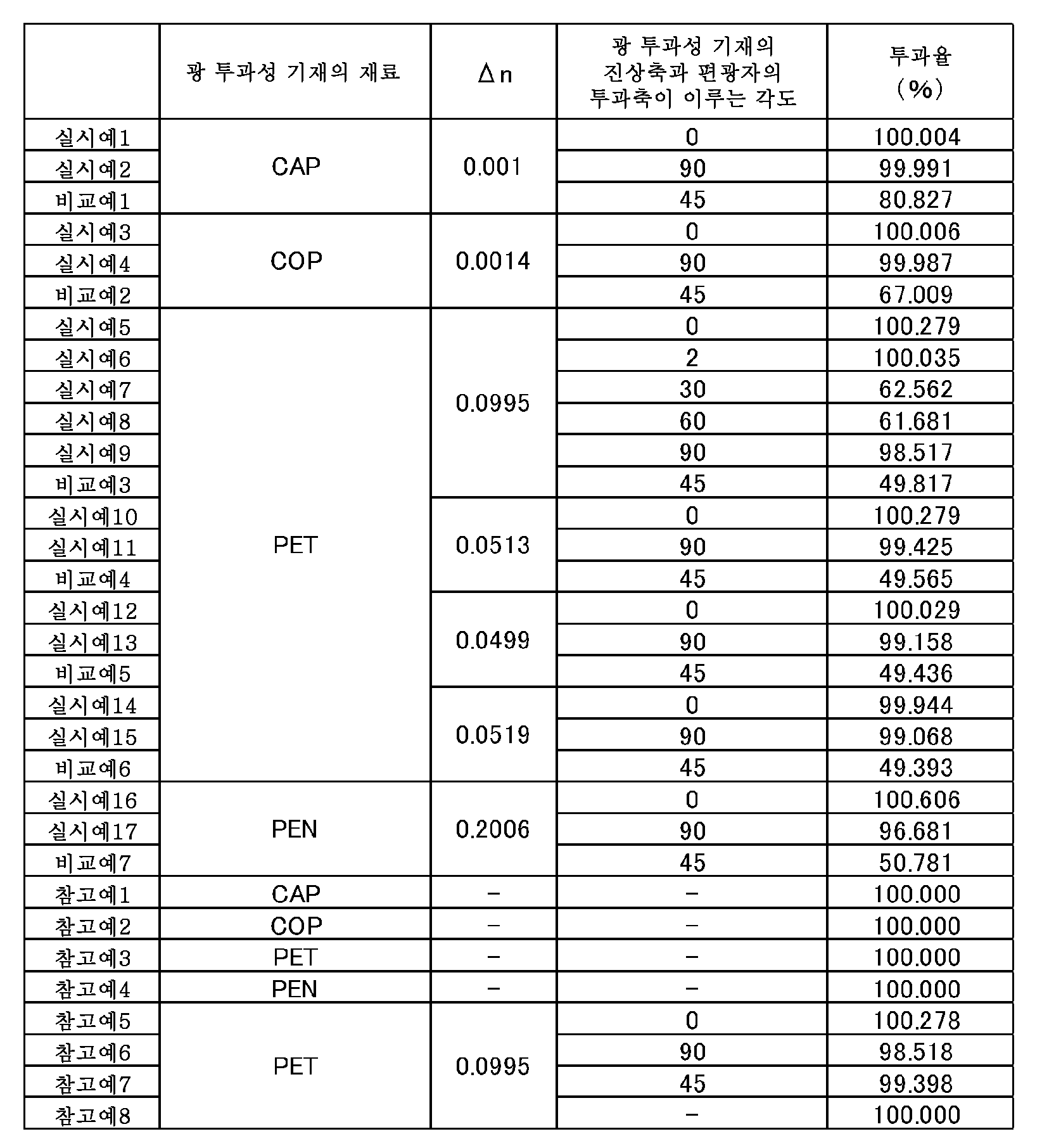
표 1에 도시한 바와 같이, 실시예 1, 2와 비교예 1의 비교, 실시예 3, 4와 비교예 2의 비교, 실시예 5 내지 9와 비교예 3의 비교, 실시예 10, 11과 비교예 4의 비교, 실시예 12, 13과 비교예 5의 비교, 실시예 14, 15와 비교예 6의 비교 및 실시예 16, 17과 비교예 7의 비교에서, 광 투과성 기재의 지상축과 편광자의 투과축이 소정의 각도 범위 내에 있는 실시예에 관한 편광판은, 당해 각도 범위를 벗어나는 비교예에 관한 편광판보다도 광 투과성이 우수했다. As shown in Table 1, the comparison of Examples 1 and 2 and Comparative Example 1, the comparison of Examples 3 and 4 and Comparative Example 2, the comparison of Examples 5 to 9 and Comparative Example 3, Comparison of Comparative Example 4, Comparison of Examples 12 and 13 and Comparative Example 5, Comparison of Examples 14 and 15 and Comparative Example 6, and Comparison of Examples 16 and 17 and Comparative Example 7 show that the light- The polarizing plate according to the example in which the transmission axis of the polarizer was within a predetermined angle range was superior in light transmittance to the polarizing plate according to the comparative example deviating from the angle range.
또한, 실시예 1과 참고예 1의 비교, 실시예 3과 참고예 2의 비교, 실시예 5, 10, 12와 참고예 3의 비교, 실시예 16과 참고예 4의 비교에서, 면 내에 복굴절률을 갖는 광 투과성 기재를 사용한 실시예에 관한 편광판은, 면 내에 복굴절률을 갖지 않는 광 투과성 기재를 사용한 비교예에 관한 편광판보다도 광 투과성이 우수했다. In comparison between Example 1 and Reference Example 1, Comparison between Example 3 and Reference Example 2, Comparison between Examples 5, 10 and 12 and Reference Example 3, and Comparison between Example 16 and Reference Example 4, The polarizing plate according to the example using the light-transmitting base material having a refractive index was superior in light transmittance to the polarizing plate according to the comparative example using a light-transmitting base material having no birefringence in the plane.
실시예 5, 9, 비교예 3, 참고예 3과, 참고예 5 내지 8의 비교에서, 편광된 광이 입사됨으로써, 광 투과성 기재의 지상축과 편광자의 투과축이 소정의 각도 범위 내에 있는 실시예에 관한 편광판은, 당해 각도 범위를 벗어나는 비교예에 관한 편광판보다도 광 투과성이 우수한 것을 확인할 수 있었다. In the comparison of Examples 5, 9, Comparative Example 3, Reference Example 3, and Reference Examples 5 to 8, it was confirmed that the polarized light was incident, so that the slow axis of the light transmitting base and the transmission axis of the polarizer were within a predetermined angular range It was confirmed that the polarizing plate of the example was superior in light transmittance to the polarizing plate of the comparative example deviating from the angle range.
산업상 이용가능성 Industrial availability
본 발명의 편광판은, 면 내에 복굴절률을 갖는 광 투과성 기재가 사용된 경우라도, 광 투과율이 우수한 것이 되고, 또한 종래의 면 내에 위상차를 갖지 않는 트리아세틸셀룰로오스로 대표되는 셀룰로오스에스테르를 포함하는 필름이 사용된 편광판이어도, 굳이 복굴절률을 갖게 함으로써, 투과율이 우수한 것이 되며, 액정 디스플레이(LCD)의 백라이트 광원 측에 배치되는 편광판으로서 적절하게 사용할 수 있다.The polarizing plate of the present invention is excellent in light transmittance even when a light-transmitting base material having a birefringence in a plane is used, and a film comprising a cellulose ester represented by triacetylcellulose having no retardation in the conventional plane Even a used polarizing plate can be suitably used as a polarizing plate disposed on the backlight source side of a liquid crystal display (LCD) by having a birefringent index so as to be excellent in transmittance.
Claims (10)
상기 면 내에 복굴절률을 갖는 광 투과성 기재에, 편광된 광이 입사되는 것이고,
상기 면 내에 복굴절률을 갖는 광 투과성 기재와 상기 편광자는, 상기 면 내에 복굴절률을 갖는 광 투과성 기재의 굴절률이 작은 방향인 진상축과 상기 편광자의 투과축이 이루는 각도가, 0°±30° 또는 90°±30°로 되도록 적층되어 있는
것을 특징으로 하는, 편광판. A polarizing plate used from at least a backlight light source side, wherein at least a light transmitting base material having a birefringent index in a plane and a polarizer are stacked in this order and arranged on the backlight light source side of the image display device,
The polarized light is incident on a light-transmitting base material having a birefringence in the plane,
And the polarizer has an angle formed by the fast axis which is a direction in which the refractive index of the light transmitting base material having a birefringence in the plane is small and the transmission axis of the polarizer is 0 占 30 占 or 90 占 占 30 占
And a polarizer.
nx>N>ny 2. The optical element according to claim 1, wherein the refractive index nx in the slow axis direction, which is the direction in which the refractive index of the light-transmitting substrate having the birefringence in the plane is large, the refractive index ny in the fast axis direction perpendicular to the slow axis direction, Wherein an average refractive index (N) of the light-transmitting base material has a relationship represented by the following formula and the angle formed by the fast axis and the transmission axis of the polarizer is 0 占 占 占.
nx>n> ny
상기 면 내에 복굴절률을 갖는 광 투과성 기재와 상기 편광자를, 상기 면 내에 복굴절률을 갖는 광 투과성 기재의 굴절률이 작은 방향인 진상축과 상기 편광자의 투과축이 이루는 각도가, 0°±30° 또는 90°±30°로 되도록 적층하는 공정을 갖는 것을 특징으로 하는, 편광판의 제조 방법. A method of producing a polarizing plate, which is used at least on a backlight light source side of an image display apparatus in which a light transmitting base material having a birefringence in a plane and a polarizer are stacked in this order,
An angle formed by a transmission axis of the polarizer and a fast axis which is a direction in which a refractive index of a light transmitting base material having a birefringent index in the plane is small is 0 占 30 占 or 90 占 占 30 占 The polarizing plate according to claim 1,
상기 면 내에 복굴절률을 갖는 상부 광 투과성 기재와 상기 상부 편광자는, 상기 면 내에 복굴절률을 갖는 상부 광 투과성 기재의 굴절률이 작은 방향인 진상축과 상기 상부 편광자의 투과축이 이루는 각도가 90°로 되지 않도록 배치되어 있는, 화상 표시 장치.The liquid crystal display device according to claim 6 or 7, further comprising an upper polarizer plate provided on the observer side, the upper transparent base material having a birefringence in the plane at least on the upper polarizer,
The upper light-transmitting substrate having a birefringence in the plane and the upper polarizer are arranged such that an angle formed by a fast axis in a direction in which the refractive index of the upper light-transmitting substrate having a birefringence in the plane is small and a transmission axis of the upper polarizer is 90 And is arranged so as not to be in contact with the surface.
상기 면 내에 복굴절률을 갖는 광 투과성 기재와 상기 편광자를, 상기 면 내에 복굴절률을 갖는 광 투과성 기재의 굴절률이 작은 방향인 진상축과 상기 편광자의 투과축이 이루는 각도가, 0°±30° 또는 90°±30°로 되도록 적층하는 공정을 갖는 것을 특징으로 하는 화상 표시 장치의 제조 방법. A method of manufacturing an image display device comprising a polarizing plate at least a light transmitting base material having a birefringent index in a plane and a polarizer stacked in this order and arranged on a backlight source side of an image display apparatus,
An angle formed by a transmission axis of the polarizer and a fast axis which is a direction in which a refractive index of a light transmitting base material having a birefringent index in the plane is small is 0 占 30 占 or 90 占 占 30 占 The manufacturing method of an image display apparatus according to claim 1,
상기 면 내에 복굴절률을 갖는 광 투과성 기재와 상기 편광자를, 상기 면 내에 복굴절률을 갖는 광 투과성 기재의 굴절률이 작은 방향인 진상축과 상기 편광자의 투과축이 이루는 각도가, 0°±30° 또는 90°±30°로 되도록 적층하는 것을 특징으로 하는 편광판의 광 투과율 개선 방법.A method for improving the light transmittance of a polarizing plate, which is used at least on a backlight light source side of an image display apparatus in which a light transmitting base material having a birefringent index in a plane and a polarizer are stacked in this order,
An angle formed by a transmission axis of the polarizer and a fast axis which is a direction in which a refractive index of a light transmitting base material having a birefringent index in the plane is small is 0 占 30 占 or 90 DEG +/- 30 DEG. The method for improving the light transmittance of a polarizing plate according to claim 1,
Applications Claiming Priority (3)
| Application Number | Priority Date | Filing Date | Title |
|---|---|---|---|
| JPJP-P-2013-187613 | 2013-09-10 | ||
| JP2013187613A JP2015055680A (en) | 2013-09-10 | 2013-09-10 | Polarizing plate, method for manufacturing polarizing plate, image display device, method for manufacturing image display device, and method for improving light transmittance of polarizing plate |
| PCT/JP2014/070722 WO2015037369A1 (en) | 2013-09-10 | 2014-08-06 | Polarizing plate, method for manufacturing polarizing plate, image display device, method for manufacturing image display device, and method for improving transmittance of polarizing plate |
Publications (1)
| Publication Number | Publication Date |
|---|---|
| KR20160055152A true KR20160055152A (en) | 2016-05-17 |
Family
ID=52665488
Family Applications (1)
| Application Number | Title | Priority Date | Filing Date |
|---|---|---|---|
| KR1020167006638A Withdrawn KR20160055152A (en) | 2013-09-10 | 2014-08-06 | Polarizing plate, method for manufacturing polarizing plate, image display device, method for manufacturing image display device, and method for improving transmittance of polarizing plate |
Country Status (6)
| Country | Link |
|---|---|
| US (1) | US10310153B2 (en) |
| JP (1) | JP2015055680A (en) |
| KR (1) | KR20160055152A (en) |
| CN (2) | CN105518496A (en) |
| TW (2) | TWI670528B (en) |
| WO (1) | WO2015037369A1 (en) |
Families Citing this family (13)
| Publication number | Priority date | Publication date | Assignee | Title |
|---|---|---|---|---|
| JP4888853B2 (en) | 2009-11-12 | 2012-02-29 | 学校法人慶應義塾 | Method for improving visibility of liquid crystal display device, and liquid crystal display device using the same |
| CN102959459B (en) | 2010-06-22 | 2019-06-18 | 东洋纺株式会社 | Liquid crystal display device, polarizing plate and polarizing plate protective film |
| US10175494B2 (en) | 2011-05-18 | 2019-01-08 | Toyobo Co., Ltd. | Polarizing plate suitable for liquid crystal display device capable of displaying three-dimensional images, and liquid crystal display device |
| CN103547961B (en) | 2011-05-18 | 2017-07-14 | 东洋纺株式会社 | Liquid crystal display device, polarizing plate, and polarizing plate protective film |
| JP6843491B2 (en) * | 2014-02-17 | 2021-03-17 | 大日本印刷株式会社 | Laminates, methods for manufacturing laminates, image display devices, methods for manufacturing image display devices, and methods for improving the light transmittance of polarizing plates |
| KR20180023953A (en) * | 2015-07-16 | 2018-03-07 | 도요보 가부시키가이샤 | Liquid crystal display and polarizer |
| JP6907463B2 (en) * | 2016-03-16 | 2021-07-21 | 東洋紡株式会社 | Liquid crystal display device |
| JP6907462B2 (en) * | 2016-03-16 | 2021-07-21 | 東洋紡株式会社 | Liquid crystal display device |
| JP6874297B2 (en) * | 2016-08-18 | 2021-05-19 | 東洋紡株式会社 | Liquid crystal display device |
| JP6874298B2 (en) * | 2016-08-18 | 2021-05-19 | 東洋紡株式会社 | Liquid crystal display device |
| CN108427221A (en) * | 2017-02-13 | 2018-08-21 | 斯坦雷电气株式会社 | Display device |
| CN110959125B (en) * | 2017-07-25 | 2022-03-18 | 日本瑞翁株式会社 | Laminate |
| CN119493287B (en) * | 2023-08-14 | 2025-07-25 | 北京字跳网络技术有限公司 | Optical module, manufacturing method thereof and near-eye display device |
Family Cites Families (26)
| Publication number | Priority date | Publication date | Assignee | Title |
|---|---|---|---|---|
| JPS5977401A (en) | 1982-09-22 | 1984-05-02 | Nitto Electric Ind Co Ltd | Polarizing plate |
| JPH0651120A (en) | 1992-07-29 | 1994-02-25 | Nitto Denko Corp | Polarizing plate and liquid crystal display device |
| US6292242B1 (en) * | 1993-12-15 | 2001-09-18 | Ois Optical Imaging Systems, Inc. | Normally white twisted nematic LCD with positive uniaxial and negative biaxial retarders |
| US5594568A (en) * | 1993-12-15 | 1997-01-14 | Ois Optical Imaging Systems, Inc. | LCD with a pair of retardation films on one side of normally white liquid crystal layer |
| JP4374859B2 (en) * | 2003-01-23 | 2009-12-02 | 東レ株式会社 | Support film for polarizing film and polarizing plate |
| US20070013844A1 (en) * | 2005-07-12 | 2007-01-18 | Nitto Denko Corporation | Liquid crystal panel and liquid crystal display using the same |
| KR101354361B1 (en) * | 2006-02-28 | 2014-01-22 | 데이진 가부시키가이샤 | Layered polarization film, phase difference film, and liquid crystal display device |
| US20070236636A1 (en) * | 2006-03-31 | 2007-10-11 | Watson Philip E | Contrast ratio enhancement optical stack |
| KR20080034405A (en) * | 2006-10-16 | 2008-04-21 | 다이니폰 인사츠 가부시키가이샤 | Retardation film and polarizer |
| JP5393048B2 (en) * | 2007-06-29 | 2014-01-22 | 日東電工株式会社 | Liquid crystal display device, laminated polarizing plate, and polarized light source device |
| JP5000717B2 (en) * | 2007-07-24 | 2012-08-15 | シャープ株式会社 | Liquid crystal display device and polarizing plate |
| TWI453123B (en) | 2007-12-03 | 2014-09-21 | Sumitomo Chemical Co | A set of polarizer, and a liquid crystal panel and an apparatus of liquid crystal display used thereof |
| JP2009157343A (en) * | 2007-12-04 | 2009-07-16 | Sumitomo Chemical Co Ltd | Polarizing plate and liquid crystal display device using the same |
| JP2009169389A (en) * | 2007-12-18 | 2009-07-30 | Sumitomo Chemical Co Ltd | Set of polarizing plates, and liquid crystal panel and liquid crystal display device using the same |
| JP2010112986A (en) * | 2008-11-04 | 2010-05-20 | Konica Minolta Opto Inc | Method for producing optical film, optical film production device, optical film and liquid crystal display |
| WO2010087058A1 (en) * | 2009-01-27 | 2010-08-05 | シャープ株式会社 | Liquid crystal display apparatus |
| JP2010217844A (en) | 2009-03-19 | 2010-09-30 | Sumitomo Chemical Co Ltd | Polarizing plate set, liquid crystal panel using the same, and liquid crystal display device |
| JP4792545B2 (en) * | 2009-05-27 | 2011-10-12 | シャープ株式会社 | Liquid crystal display |
| JP5519217B2 (en) * | 2009-08-31 | 2014-06-11 | 帝人デュポンフィルム株式会社 | Film for polarizer support substrate |
| JP5811431B2 (en) | 2009-09-11 | 2015-11-11 | 住友化学株式会社 | Polarizing plate and liquid crystal display device |
| JP5568808B2 (en) | 2009-10-20 | 2014-08-13 | 住友化学株式会社 | Liquid crystal display device having backlight and optical member set for liquid crystal display device |
| JP5377252B2 (en) | 2009-11-27 | 2013-12-25 | 日東電工株式会社 | Image display device |
| CN102959459B (en) * | 2010-06-22 | 2019-06-18 | 东洋纺株式会社 | Liquid crystal display device, polarizing plate and polarizing plate protective film |
| JP5804079B2 (en) * | 2011-11-29 | 2015-11-04 | 東洋紡株式会社 | Liquid crystal display device, polarizing plate and polarizer protective film |
| KR101397702B1 (en) * | 2011-12-26 | 2014-05-22 | 제일모직주식회사 | Polarizing plate and liquid crystal display comprising the same |
| KR101631350B1 (en) * | 2012-12-17 | 2016-06-16 | 제일모직주식회사 | Polarizing plate and liquid crystal display apparatus comprising the same |
-
2013
- 2013-09-10 JP JP2013187613A patent/JP2015055680A/en active Pending
-
2014
- 2014-08-06 CN CN201480049413.7A patent/CN105518496A/en active Pending
- 2014-08-06 US US14/917,189 patent/US10310153B2/en active Active
- 2014-08-06 KR KR1020167006638A patent/KR20160055152A/en not_active Withdrawn
- 2014-08-06 CN CN201710906341.9A patent/CN107765358A/en active Pending
- 2014-08-06 WO PCT/JP2014/070722 patent/WO2015037369A1/en not_active Ceased
- 2014-08-11 TW TW103127418A patent/TWI670528B/en active
- 2014-08-11 TW TW107137365A patent/TW201903443A/en unknown
Also Published As
| Publication number | Publication date |
|---|---|
| TWI670528B (en) | 2019-09-01 |
| US10310153B2 (en) | 2019-06-04 |
| TW201510588A (en) | 2015-03-16 |
| WO2015037369A1 (en) | 2015-03-19 |
| CN107765358A (en) | 2018-03-06 |
| CN105518496A (en) | 2016-04-20 |
| US20160209564A1 (en) | 2016-07-21 |
| TW201903443A (en) | 2019-01-16 |
| JP2015055680A (en) | 2015-03-23 |
Similar Documents
| Publication | Publication Date | Title |
|---|---|---|
| TWI670528B (en) | Polarizing plate, manufacturing method of polarizing plate, image display device, manufacturing method of image display device, and light transmittance improving method of polarizing plate | |
| US11982896B2 (en) | Liquid crystal display device and polarizing plate | |
| TWI550319B (en) | An optical member, a polarizing plate group, and a liquid crystal display device | |
| JP2010152374A (en) | Polarizer, optical film using the same, and image display device using them | |
| JPWO2015147287A1 (en) | Liquid crystal panel, liquid crystal display device, polarizing plate, and polarizing plate protective film | |
| EP3401894A1 (en) | Image display device | |
| JP6263860B2 (en) | Optical laminate and display quality improving method for image display device | |
| TW201816434A (en) | Optical member | |
| JP4975236B2 (en) | Polarizer, optical film using the same, and image display device using the same | |
| CN101251614A (en) | Laminated retardation film | |
| JP2010015038A (en) | Liquid crystal display device | |
| JP2010204224A (en) | Polarizing plate, method of manufacturing the same, and liquid crystal display device | |
| US20230221600A1 (en) | Liquid crystal display device | |
| JP7259762B2 (en) | Circularly polarizing plate, long broadband λ/4 plate, organic electroluminescence display device and liquid crystal display device | |
| JP2017062500A (en) | Polarizing plate, method for manufacturing polarizing plate, image display device, method for manufacturing image display device, and method for improving light transmittance of polarizing plate | |
| JP2015055679A (en) | Polarizing plate, method for manufacturing polarizing plate, image display device, method for manufacturing image display device, and method for improving light transmittance of polarizing plate | |
| JP2005031557A (en) | Norbornene-based optical compensation film and method for producing the same | |
| JP6843491B2 (en) | Laminates, methods for manufacturing laminates, image display devices, methods for manufacturing image display devices, and methods for improving the light transmittance of polarizing plates | |
| JP2018077529A (en) | Polarizing plate, method for manufacturing polarizing plate, image display device, method for manufacturing image display device, and method for improving light transmittance of polarizing plate |
Legal Events
| Date | Code | Title | Description |
|---|---|---|---|
| PA0105 | International application |
Patent event date: 20160314 Patent event code: PA01051R01D Comment text: International Patent Application |
|
| PG1501 | Laying open of application | ||
| PC1203 | Withdrawal of no request for examination | ||
| WITN | Application deemed withdrawn, e.g. because no request for examination was filed or no examination fee was paid |