KR20160054471A - Chlorine dioxide production device and chlorine dioxide production method - Google Patents
Chlorine dioxide production device and chlorine dioxide production method Download PDFInfo
- Publication number
- KR20160054471A KR20160054471A KR1020167005801A KR20167005801A KR20160054471A KR 20160054471 A KR20160054471 A KR 20160054471A KR 1020167005801 A KR1020167005801 A KR 1020167005801A KR 20167005801 A KR20167005801 A KR 20167005801A KR 20160054471 A KR20160054471 A KR 20160054471A
- Authority
- KR
- South Korea
- Prior art keywords
- chlorine dioxide
- chamber
- aeration
- anode chamber
- anode
- Prior art date
Links
Images


Classifications
-
- C—CHEMISTRY; METALLURGY
- C25—ELECTROLYTIC OR ELECTROPHORETIC PROCESSES; APPARATUS THEREFOR
- C25B—ELECTROLYTIC OR ELECTROPHORETIC PROCESSES FOR THE PRODUCTION OF COMPOUNDS OR NON-METALS; APPARATUS THEREFOR
- C25B1/00—Electrolytic production of inorganic compounds or non-metals
- C25B1/01—Products
- C25B1/24—Halogens or compounds thereof
- C25B1/26—Chlorine; Compounds thereof
-
- C—CHEMISTRY; METALLURGY
- C25—ELECTROLYTIC OR ELECTROPHORETIC PROCESSES; APPARATUS THEREFOR
- C25B—ELECTROLYTIC OR ELECTROPHORETIC PROCESSES FOR THE PRODUCTION OF COMPOUNDS OR NON-METALS; APPARATUS THEREFOR
- C25B15/00—Operating or servicing cells
- C25B15/02—Process control or regulation
-
- C—CHEMISTRY; METALLURGY
- C25—ELECTROLYTIC OR ELECTROPHORETIC PROCESSES; APPARATUS THEREFOR
- C25B—ELECTROLYTIC OR ELECTROPHORETIC PROCESSES FOR THE PRODUCTION OF COMPOUNDS OR NON-METALS; APPARATUS THEREFOR
- C25B15/00—Operating or servicing cells
- C25B15/08—Supplying or removing reactants or electrolytes; Regeneration of electrolytes
-
- C25B9/08—
-
- C—CHEMISTRY; METALLURGY
- C25—ELECTROLYTIC OR ELECTROPHORETIC PROCESSES; APPARATUS THEREFOR
- C25B—ELECTROLYTIC OR ELECTROPHORETIC PROCESSES FOR THE PRODUCTION OF COMPOUNDS OR NON-METALS; APPARATUS THEREFOR
- C25B9/00—Cells or assemblies of cells; Constructional parts of cells; Assemblies of constructional parts, e.g. electrode-diaphragm assemblies; Process-related cell features
- C25B9/17—Cells comprising dimensionally-stable non-movable electrodes; Assemblies of constructional parts thereof
- C25B9/19—Cells comprising dimensionally-stable non-movable electrodes; Assemblies of constructional parts thereof with diaphragms
Abstract
양극실(3)과 음극실(5)을 가지고, 양극실(3)에 공급된 아염소산염을 포함하는 양극액을 전해 처리하여 이산화염소를 발생하게 하는 격막식 전해조(2)와, 양극실(3)과 음극실(5)을 연통하는 유로부(C)와, 음극실(5)과 외부를 연통하는 배출부(D)와, 공급량 조절 가능하게 폭기 기체를 양극실에 공급하는 폭기 수단(14)과, 음극실(5) 및 배출부(D)의 적어도 어느 한쪽에 중화제를 공급하는 중화 수단(12)을 구비한 이산화염소 제조 장치(1)가 제공된다. A diaphragm type electrolytic cell 2 having an anode chamber 3 and a cathode chamber 5 and electrolytically treating an anode liquid containing chlorosalt supplied to the anode chamber 3 to generate chlorine dioxide; A discharge portion D which communicates with the outside of the cathode chamber 5 and an aeration means which supplies the aeration gas to the anode chamber so as to adjust the supply amount And a neutralization means (12) for supplying a neutralizing agent to at least one of the cathode chamber (5) and the discharge portion (D).
Description
본 발명은, 양극실과 음극실을 가지는 격막식 전해조를 사용하여 아염소산염을 포함하는 양극액을 전기 분해함으로써 이산화염소를 제조하는 장치 및 방법에 관한 것이다. The present invention relates to an apparatus and a method for producing chlorine dioxide by electrolyzing a catholyte-containing anolyte using a diaphragm electrolytic cell having an anode chamber and a cathode chamber.
종래의 이산화염소 제조 장치 및 이산화염소 제조 방법으로서는, 예를 들면 이하의 특허문헌 1에 나타낸 것을 들 수 있다. 이 문헌에는, 격막식 전해조의 양극실 및 음극실의 각각에, 아염소산염을 포함하는 양극액 및 수산화나트륨이나 염화나트륨 등을 포함하는 음극액을 공급하면서 전해 처리를 실시하여 이산화염소를 발생하게 하는 장치 및 방법이 기재되어 있다. Examples of the conventional chlorine dioxide producing apparatus and chlorine dioxide producing method are shown in Patent Document 1 below. In this document, an electrolytic treatment is performed while an anolyte solution containing chlorite and a catholyte solution containing sodium hydroxide or sodium chloride are supplied to each of an anode chamber and a cathode chamber of a diaphragm electrolytic cell to generate chlorine dioxide And methods are described.
격막식 전해조를 구비하는 이산화염소 제조 장치는, 격막을 사용하지 않는 1액형의 이산화염소 제조 장치와 비교해서 이산화염소의 생성 효율이 높다. 그 반면, 발생한 이산화염소가 장치 내에서 고농도로 되기 쉽고, 폭발을 일으킬 위험성이 높아지기 때문에, 이산화염소를 가능한 한 신속하게 희석할 필요가 있다. 상기 특허문헌 1의 이산화염소 제조 장치에서는, 이산화염소가 용존하는 양극액을, 배관을 개재하여 폭기조로 이송해서 폭기 처리함으로써 이산화염소를 회수·희석하도록 구성되어 있기 때문에, 폭기조에 이송하는 도중에, 이산화염소가 양극액에 완전히 용해되지 않게 되어 폭발할 우려가 있는 동시에, 장치 구성이 복잡한 것으로 되어 있었다. The chlorine dioxide producing apparatus provided with the diaphragm electrolytic cell has a higher production efficiency of chlorine dioxide than the one-liquid type chlorine dioxide producing apparatus which does not use the diaphragm. On the other hand, it is necessary to dilute the chlorine dioxide as quickly as possible since the generated chlorine dioxide tends to become high in concentration in the apparatus and the risk of explosion increases. In the apparatus for producing chlorine dioxide of Patent Document 1, since the anolyte solution in which chlorine dioxide is dissolved is transferred to the aeration tank through the piping and subjected to aeration treatment to recover and dilute the chlorine dioxide, The chlorine does not completely dissolve in the anolyte solution, which may cause explosion, and the device configuration is complicated.
또, 전술한 이산화염소 제조 장치에서는, 양극실 및 음극실 각각에, 양극액 및 음극액을 독립적으로 공급하는 구성이었기 때문에, 양극액 및 음극액을 공급하기 위한 저류 탱크나 송액 펌프 등의 공급계가, 양극실용과 음극실용 각각에 필요하게 된다. 이에 따라, 장치 구성이 복잡화되어, 설계, 제조, 가동, 보수 점검 등 각종의 점에서 고비용이 되는 경우가 있었다. Further, in the above-described chlorine dioxide producing apparatus, since the anolyte and catholyte are independently supplied to the anode chamber and the cathode chamber, respectively, a supply system such as a reservoir tank or a feed pump for supplying the anolyte and the catholyte , And it is necessary for each of the anode and cathode chambers. As a result, the configuration of the apparatus becomes complicated, resulting in high cost in terms of various aspects such as design, manufacture, operation, maintenance, and the like.
또한, 전술한 이산화염소 제조 장치에서는, 회수되지 않고 잔류하는 이산화염소를 포함하는 양극액 및 높은 pH를 가지는 음극액 각각의 폐액 처리를 각각 행할 필요가 있기 때문에, 그 번거로움으로, 폐액 처리가 반드시 적절하게 실시되지 않을 우려가 있어, 환경 오염에 관한 걱정이 있었다. Further, in the above-described chlorine dioxide producing apparatus, it is necessary to perform each of the waste liquid treatment for each of the anolyte containing the chlorine dioxide remaining and the high-pH the catholyte which is not recovered. Therefore, There is a fear that it may not be carried out properly and there is a concern about environmental pollution.
본 발명의 목적은, 보다 간략한 구성 및 방법으로 이산화염소를 제조하고, 또한 신속하게 이산화염소의 농도를 희석할 수 있고, 또 양극액 및 음극액 각각의 폐액 처리를 간편하게 실시할 수 있는 이산화염소 제조 장치 및 이산화염소 제조 방법을 제공하는 데에 있다. It is an object of the present invention to provide a chlorine dioxide production method capable of producing chlorine dioxide by a simpler constitution and a method and also to dilute the concentration of chlorine dioxide rapidly and to make a chlorine dioxide production Apparatus and a method for producing chlorine dioxide.
본 발명의 이산화염소 제조 장치에 관한 제1 특징 구성은, 양극실과 음극실을 가지고, 상기 양극실에 공급된 아염소산염을 포함하는 양극액을 전해 처리하여 이산화염소를 발생하게 하는 격막식 전해조와, 상기 양극실과 상기 음극실을 연통하는 유로부와, 상기 음극실과 외부를 연통하는 배출부와, 공급량 조절 가능하게 폭기 기체를 상기 양극실에 공급하는 폭기 수단과, 상기 음극실 및 상기 배출부의 적어도 어느 한쪽에 중화제를 공급하는 중화 수단을 구비하고, 상기 양극실에 있어서 상기 양극액을 전해 처리하여 이산화염소를 발생하게 하고, 상기 폭기 수단에 의해 폭기 기체를 상기 양극실의 양극액에 공급함으로써, 발생한 이산화염소를 회수하고, 상기 양극실에서 전해 처리 및 폭기 처리된 후의 양극액이, 상기 유로부를 통하여 상기 음극실로 이류해서 음극액으로서 전해 처리된 후, 상기 음극실 및 상기 배출부의 적어도 어느 한쪽에서 중화 처리되도록 구성되는 점에 있다. A first characterizing feature of the chlorine dioxide producing device of the present invention is a chlorine dioxide producing device comprising a diaphragm type electrolytic cell having an anode chamber and a cathode chamber and electrolytically treating an anode liquid containing chlorosalt supplied to the anode chamber to generate chlorine dioxide, At least one of the cathode chamber and the discharging portion, at least one of the cathode chamber and the discharging portion, a flow path portion communicating the anode chamber and the cathode chamber, a discharge portion communicating with the outside of the cathode chamber, an aeration means for supplying an aeration gas to the anode chamber, And a neutralizing means for supplying a neutralizing agent to one side of the cathode chamber, and electrolyzing the anode liquid in the anode chamber to generate chlorine dioxide, and supplying an aeration gas to the anode liquid of the anode chamber by the aeration means And the anolyte after the electrolytic treatment and the aeration treatment in the anode chamber is conducted to the cathode chamber After the electrolytic treatment as second-rate to the catholyte, and in the cathode chamber and that is configured to be neutralized in at least one of said discharge.
〔작용 및 효과〕 [Action and effect]
본 구성에 의하면, 폭기 수단에 의해 폭기 기체를 양극실에 공급해서 양극액을 폭기 처리할 수 있다. 이에 따라, 발생한 이산화염소의 양극액으로의 용해를 억제하면서, 이산화염소 농도를 신속하게 희석해서 폭발을 회피하는 것이 가능해지기 때문에, 발생한 이산화염소를 보다 효율적이며 안전하게 회수할 수 있다. 또한, 폭기 기체를 양극실에 직접 공급하는 구성이므로, 별도로 폭기조 등을 설치할 필요가 없어, 장치 구성이 간소화된다. According to this configuration, the aeration means can supply the anolyte to the anode chamber by the aeration means to perform the aeration treatment of the anolyte. This makes it possible to rapidly dilute the concentration of chlorine dioxide while avoiding the dissolution of chlorine dioxide into the anolyte solution, thereby avoiding the explosion, so that the generated chlorine dioxide can be recovered more efficiently and safely. Moreover, since the aeration gas is directly supplied to the anode chamber, it is not necessary to provide an aeration tank or the like separately, and the structure of the apparatus is simplified.
또 본 구성에 의하면, 양극실에서 전해 처리 및 폭기 처리된 후의 양극액을, 유로부를 개재하여 음극실에 이류하게 하여, 그대로 음극액으로서 사용하는 것이 가능하게 된다. 종래는, 양극실 및 음극실 각각에 양극액 및 음극액을 독립적으로 공급하는 구성이었기 때문에, 양극액 및 음극액을 공급하기 위한 저류 탱크나 송액 펌프 등의 공급계가, 양극실용과 음극실용 각각에 필요하였다. 그러나, 본 구성이라면, 양극실용의 공급계만으로 가능하기 때문에, 장치 구성이 간소화되어 여러 가지 비용을 삭감할 수 있다. According to this configuration, the anolyte after the electrolytic treatment and the aeration treatment in the anode chamber is diverted to the cathode chamber via the flow path portion, and can be used as the cathode solution as it is. Conventionally, since the anolyte and catholyte are independently supplied to the anode chamber and the cathode chamber, a supply system such as a reservoir tank or a liquid delivery pump for supplying the anolyte and catholyte is provided for each of the anode chamber and the cathode chamber . However, in the case of this configuration, since only the supply system for the anode room can be used, the apparatus configuration is simplified, and various costs can be reduced.
또 본 구성에 의하면, 양극실에서 전해 처리 및 폭기 처리된 후의 양극액이, 유로부를 개재하여 음극실로 이류해서 전해 처리된다. 이에 따라, 가령, 발생한 이산화염소의 일부가 양극실에서 회수되지 않고 양극액 중에 잔류하고 있었다고 하더라도, 음극실에서 음극 환원되어 아염소산염이 된다. 또한, 음극실에서 전해 처리된 후의, 높은 pH를 가지는 음극액이, 중화 수단에서 공급되는 중화제에 의해, 음극실 및 배출부의 적어도 어느 한쪽에서 중화 처리된다. According to this configuration, the anolyte after the electrolytic treatment and the aeration treatment in the anode chamber is intercalated into the cathode chamber through the channel portion and electrolytically treated. Thus, even if some of the generated chlorine dioxide remains in the anolyte without being recovered in the anolyte chamber, the anolyte is reduced in the cathode chamber to become chlorite. Further, the catholyte having a high pH after electrolytic treatment in the cathode chamber is neutralized by at least one of the cathode chamber and the discharge portion by the neutralizing agent supplied from the neutralization means.
즉, 본 구성과 같이, 양극실에서 전해 처리 및 폭기 처리된 후의 양극액을 그대로 음극액으로서 사용하고, 음극실에서 전해 처리된 후의 음극액을 중화 처리한다고 하는 구성을 채용함으로써, 잔류 이산화염소를 포함하는 양극액, 및 높은 pH를 가지는 음극액 각각의 폐액 처리가, 각각 따로따로가 아니라, 음극실에서 배출부를 거쳐 배출되는 동안까지 통합해서 실시되게 되므로 폐액 처리가 간편화된다. That is, as in this configuration, by employing the configuration in which the anolyte after the electrolytic treatment and the aeration treatment in the anode chamber is used as the catholyte solution as it is and the catholyte after the electrolytic treatment in the cathode chamber is neutralized, residual chlorine dioxide The waste liquid treatment of each of the anolyte and the catholyte having a high pH is carried out integrally until they are discharged separately from the cathode chamber through the discharge portion.
제2 특징 구성은, 상기 격막식 전해조, 상기 유로부 및 상기 배출부가 일체화되어 있는 점에 있다. The second characterizing feature resides in that the diaphragm electrolytic bath, the flow path portion and the discharge portion are integrated.
〔작용 및 효과〕 [Action and effect]
본 구성에 의하면, 격막식 전해조, 상기 유로부 및 상기 배출부가 일체화되어 있기 때문에, 이산화염소 제조 장치의 구성을 컴팩트화 할 수 있다. According to this configuration, since the diaphragm electrolytic cell, the flow path portion, and the discharge portion are integrated, the configuration of the chlorine dioxide producing device can be made compact.
제3 특징 구성은, 상기 유로부에 탈기조를 설치하고, 상기 폭기 수단이 상기 양극실 및 상기 탈기조에 폭기 기체를 공급하도록 구성되는 점에 있다. The third feature of the present invention resides in that the channel portion is provided with a degassing vessel, and the aeration means supplies an aeration gas to the anode chamber and the degassing vessel.
〔작용 및 효과〕 [Action and effect]
본 구성에 의하면, 폭기 처리가 양극실뿐만 아니라, 탈기조에서도 실시되게 된다. 그러므로, 생성된 이산화염소 중, 양극실에서 회수되지 않았던 이산화염소를, 탈기조에서 회수할 수 있게 되어, 생성된 이산화염소를 보다 확실하게 회수할 수 있다. According to this constitution, the aeration treatment is carried out not only in the anode chamber but also in the degassing vessel. Therefore, of the produced chlorine dioxide, chlorine dioxide which has not been recovered in the anode chamber can be recovered in the deaeration tank, and the produced chlorine dioxide can be more reliably recovered.
제4 특징 구성은, 상기 배출부에 중화조를 설치하고, 상기 중화 수단이 상기 중화조에 중화제를 공급하도록 구성되는 점에 있다. A fourth feature of the present invention resides in that a neutralization tank is provided in the discharge portion, and the neutralization means supplies the neutralization agent to the neutralization tank.
〔작용 및 효과〕 [Action and effect]
본 구성과 같이, 중화 처치하는 전용의 중화조를 설치함으로써, 보다 효율적으로 중화 처리가 실시된다. As in the present configuration, neutralization treatment is performed more efficiently by providing a dedicated neutralization tank for neutralization treatment.
본 발명의 이산화염소 제조 방법에 따른 특징 구성은, 양극실과 음극실을 가지는 격막식 전해조를 사용하는 이산화염소 제조 방법으로서, 상기 격막식 전해조의 양극실에 아염소산염을 포함하는 양극액을 공급하는 공급 공정과, 상기 양극액을 전해 처리하여 이산화염소를 발생하게 하는 양극 전해 공정과, 폭기 기체를 상기 양극실의 양극액에 공급함으로써, 발생한 이산화염소를 회수하는 폭기 공정과, 상기 양극실에서 전해 처리 및 폭기 처리된 후의 양극액을, 음극액으로 하여 상기 음극실에서 전해 처리하는 음극 전해 공정과, 상기 음극실에서 전해 처리된 후의 음극액을 배출하는 배출 공정과, 상기 음극 전해 공정, 및 상기 배출 공정의 적어도 어느 한쪽에 있어서 음극액을 중화 처리하는 중화 공정을 포함하는 점에 있다. A characteristic feature of the chlorine dioxide manufacturing method of the present invention is that a chlorine dioxide manufacturing method using a diaphragm type electrolytic cell having an anode chamber and a cathode chamber is characterized in that the anode chamber of the diaphragm electrolytic cell is supplied with an anode solution containing chlorate An anodizing step of electrolyzing the anolyte to generate chlorine dioxide; an aeration step of recovering chlorine dioxide generated by feeding an aeration gas to the anolyte of the anolyte chamber; A negative electrode electrolysis step of electrolyzing the positive electrode liquid after the aeration treatment in the negative electrode chamber as a negative electrode liquid; a discharging step of discharging the negative electrode liquid after electrolytic treatment in the negative electrode chamber; And a neutralization step of neutralizing the catholyte in at least one of the steps.
〔작용 및 효과〕 [Action and effect]
본 구성에 의하면, 폭기 공정에 의해 폭기 기체를 양극실에 공급하여 양극액을 폭기 처리할 수 있다. 이에 따라, 발생한 이산화염소의 양극액으로의 용해를 억제하면서, 이산화염소 농도를 신속하게 희석해서 폭발을 회피하는 것이 가능해지기 때문에, 발생한 이산화염소를 보다 효율적이고 또한 안전하게 회수할 수 있다. According to this configuration, the aeration gas can be supplied to the anode chamber by the aeration process to aeration the anode liquor. This makes it possible to rapidly dilute the chlorine dioxide concentration while avoiding dissolution of generated chlorine dioxide into the anolyte solution, thereby avoiding explosion, so that the generated chlorine dioxide can be recovered more efficiently and safely.
또 본 구성에 의하면, 양극실에서 전해 처리된 후의 양극액을, 그대로 음극액으로서 사용하기 때문에, 음극실에 별도의 음극액을 공급하는 공정이 불필요하게 되고, 제조 방법이 간소화되어 여러가지 비용을 삭감할 수 있다. According to this configuration, since the anolyte after the electrolytic treatment in the anode chamber is used as the catholyte solution as it is, a step of supplying a separate catholyte to the cathode chamber becomes unnecessary, the manufacturing method is simplified, and various costs are reduced can do.
또 본 구성에 의하면, 양극실에서 전해 처리 및 폭기 처리된 후의 양극액이, 음극액으로서 음극실에서 전해 처리되기 때문에, 가령, 발생한 이산화염소의 일부가 양극실에서 회수되지 않고 양극액 중에 잔류해 있다고 하더라도, 음극실에서 음극 환원되어 아염소산염 등이 된다. 또한, 음극실에서 전해 처리된 후의, 높은 pH를 가지는 음극액이, 음극 전해 공정, 및 배출 공정의 적어도 어느 한쪽에서 중화 처리된다. According to this configuration, since the anolyte after the electrolytic treatment and the aeration treatment in the anode chamber is electrolytically treated in the cathode chamber as the cathode solution, a part of the generated chlorine dioxide is not collected in the anode chamber and remains in the anolyte The anode is reduced in the cathode chamber to become chlorite or the like. Further, the catholyte having a high pH after electrolytic treatment in the cathode chamber is neutralized in at least one of the cathode electrolytic process and the discharge process.
즉, 본 구성과 같이, 양극실에서 전해 처리 및 폭기 처리된 후의 양극액을 그대로 음극액으로서 사용하고, 음극실에서 전해 처리된 후의 음극액을 중화 처리한다고 하는 구성을 채용함으로써, 잔류 이산화염소를 포함하는 양극액, 및 높은 pH를 가지는 음극액 각각의 폐액 처리가, 각각 따로따로가 아니라, 음극실에서 배출되는 동안까지 통합해서 실시되게 되므로 폐액 처리가 간편화된다. That is, as in this configuration, by employing the configuration in which the anolyte after the electrolytic treatment and the aeration treatment in the anode chamber is used as the catholyte solution as it is and the catholyte after the electrolytic treatment in the cathode chamber is neutralized, residual chlorine dioxide The waste liquid treatment of each of the anolyte and the catholyte having a high pH is carried out integrally until they are discharged from the cathode chamber, not separately.
도 1은 본 발명의 이산화염소 제조 장치의 개략적인 흐름도.
도 2는 본 발명의 이산화염소 제조 장치의 분해 사시도.
도 3은 제2 판형 부재의 종단면도.
도 4는 제3 판형 부재의 종단면도. 1 is a schematic flow chart of an apparatus for producing chlorine dioxide according to the present invention;
2 is an exploded perspective view of the chlorine dioxide producing apparatus of the present invention.
3 is a longitudinal sectional view of the second plate-shaped member.
4 is a longitudinal sectional view of the third plate-shaped member.
이하, 본 발명의 이산화염소 제조 장치 및 이산화염소 제조 방법의 일 실시예를 설명한다. Hereinafter, one embodiment of the chlorine dioxide producing apparatus and the chlorine dioxide producing method of the present invention will be described.
〔실시예〕 [Examples]
〔1〕 이산화염소 제조 장치 [1] Chlorine dioxide production equipment
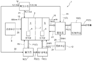
도 1에 도시한 바와 같이, 본 실시예에 따른 이산화염소 제조 장치(1)는, 양극실(3)과 음극실(5)을 가지는 격막식 전해조(2), 아염소산염을 포함하는 양극액을 격막식 전해조(2)에 공급하는 공급 수단(8), 탈기조(9), 제1 배액조(10), 전해 처리후의 음극액을 중화 처리하는 중화조(11), 중화제를 공급하는 중화 수단(12), 제2 배액조(13), 및 폭기 기체를 공급하는 폭기 수단(14)을 구비해서 구성된다. 1, the chlorine dioxide production apparatus 1 according to the present embodiment includes a diaphragm type
양극실(3)과 탈기조(9)가 제1 연통로(P1)에 의해 연통되고, 탈기조(9)와 제1 배액조(10)가 제2 연통로(P2)에 의해 연통되고, 제1 배액조(10)와 음극실(5)이 제3 연통로(P3)에 의해 연통되고, 음극실(5)과 중화조(11)가 제4 연통로(P4)에 의해 연통되고, 중화조(11)와 제2 배액조(13)가 제5 연통로(P5)에 의해 연통되어 있다. 다시 말해, 이산화염소 제조 장치(1)는, 제1~제5 연통로(P1~P5)에 의해 양극실(3), 탈기조(9), 제1 배액조(10), 음극실(5), 중화조(11), 제2 배액조(13)가 직렬적으로 연통 접속되어 있다. The
또한, 본 실시예에 있어서, 양극실(3)과 음극실(5)을 연통하는 유로부(C)가, 제1 연통로(P1), 탈기조(9), 제2 연통로(P2), 제1 배액조(10), 및 제3 연통로(P3)에 의해 형성되어 있다. 그러나, 유로부(C)는 이 구성에 한정되는 것이 아니라, 예를 들면, 탈기조(9)나 제1 배액조(10) 등을 설치하지 않고 제1 연통로(P1)만으로 구성하고, 양극실(3)과 음극실(5)을 직접 연통시키는 구성으로 하여도 된다. In this embodiment, the flow path portion C for communicating the
또 본 실시예에 있어서, 음극실(5)과 외부를 연통하는 배출부(D)가, 제4 연통로(P4), 중화조(11), 제5 연통로(P5), 제2 배액조(13), 및 배액관(17)에 의해 형성되어 있다. 그러나, 배출부(D)는 이 구성에 한정되는 것이 아니라, 예를 들면, 중화조(11)나 제2 배액조(13) 등을 설치하지 않고 배액관(17)만으로 구성하고, 음극실(5)과 외부를 직접 연통시키는 구성으로 하여도 된다. 다만 이 경우, 중화 수단(12)은 음극실(5)에 중화제를 공급하는 구성이 된다. In this embodiment, the discharge portion D that communicates with the
(격막식 전해조) (Diaphragm electrolytic cell)
격막식 전해조(2)로서는, 양극실(3)과 음극실(5)이 양이온 교환막(7)에 의해 나누어져 있는 종래 공지의 전해조를 사용할 수 있다. As the diaphragm type
양극실(3) 및 음극실(5) 각각은, 전극으로서 양극(4) 및 음극(6)이 설치되어 있다. 이들 전극에 대해서는, 종래 공지의 것을 사용할 수 있다. 예를 들면, 음극 재료로서는, 티타늄, 스테인리스강, 니켈, 니켈·크롬 합금, 또는 다른 밸브 금속을 들 수 있다. 또, 양극 재료로서는, 백금, 금, 팔라듐, 이리듐, 로듐, 또는 루테늄 등의 귀금속, 흑연, 흑연 펠트, 다층 흑연포, 흑연직포, 탄소, 혹은 티타늄 상에 백금을 전기 도금한 백금 피복 재료, 티타늄, 탄탈, 니오브, 또는 지르코늄의 밸브 금속 산화물로 구성된 전극 등을 들 수 있고, 전극 촉매를 코팅한 것이 바람직하게 사용된다. Each of the
양이온 교환막(7)에 대해서도 종래 공지의 것을 사용할 수 있으나, 선택투과성, 내구성 등이 우수한 플루오로 카본계의 양이온 교환막(7)이 바람직하다. Conventionally known ones can be used for the cation exchange membrane 7, but a fluorocarbon-based cation exchange membrane 7 having excellent selectivity and durability is preferable.
(중화 수단) (Neutralization means)
본 실시예에 있어서의 중화 수단(12)은 음극실(5) 및 중화조(11)의 적어도 어느 한쪽에 중화제를 공급하도록 구성되어 있다. 그러나, 중화 수단(12)은 이 구성에 한정되는 것이 아니라, 음극실(5) 및 배출부(D)의 적어도 어느 한쪽에서 중화 처리하는 구성으로 하면 된다. 배출부(D)에서 중화 처리할 경우, 예를 들면, 중화조(11)에 한정되지 않고, 배출부(D)를 구성하는, 제4 연통로(P4), 제5 연통로(P5), 제2 배액조(13) 및 배액관(17) 중 어느 하나에 중화제를 공급하도록 하여도 된다. The neutralization means 12 in the present embodiment is configured to supply a neutralizing agent to at least one of the
중화 수단(12)으로서는, 종래 공지의 구성, 예를 들면, 중화제를 저류하는 저류 탱크, 송액 펌프, 및 송액관 등을 구비한 것을 사용할 수 있다. 사용 가능한 중화제로서는, 예를 들면, 염산, 황산, 구연산, 푸마르산, 포름산, 락트산, 인산, 타르타르산, 부티르산, 각종 인산염 등을 들 수 있다. 이들은 1종을 단독으로 사용하여도 되고, 2종 이상을 병용하여도 된다. As the neutralization means 12, it is possible to use a conventionally known structure, for example, one having a reservoir tank for storing a neutralizing agent, a liquid delivery pump, and a liquid delivery pipe. Examples of usable neutralizing agents include hydrochloric acid, sulfuric acid, citric acid, fumaric acid, formic acid, lactic acid, phosphoric acid, tartaric acid, butyric acid and various phosphates. These may be used alone, or two or more of them may be used in combination.
(공급 수단) (Supply means)
공급 수단(8)으로서는, 종래 공지의 구성, 예를 들면, 아염소산염을 포함하는 양극액을 저류하는 저류 탱크, 송액 펌프, 및 송액관 등을 구비한 것을 사용할 수 있다. 사용 가능한 아염소산염으로서는, 예를 들면 아염소산 알칼리금속염이나 아염소산 알칼리토류 금속염을 들 수 있다. 아염소산 알칼리금속염으로서는, 예를 들면, 아염소산나트륨, 아염소산칼륨, 아염소산리튬을 들 수 있고, 아염소산 알칼리토류 금속염으로서는, 아염소산칼슘, 아염소산마그네슘, 아염소산바륨을 들 수 있다. 그 중에서도, 입수가 용이하다고 하는 점에서, 아염소산 나트륨, 아염소산 칼륨이 바람직하고, 아염소산 나트륨이 가장 바람직하다. 이들 아염소산염은 1종을 단독으로 사용하여도 되고, 2종 이상을 병용하여도 된다. 양극액에 있어서의 아염소산염의 농도는, 이산화염소의 발생 효율, 안전성, 안정성, 아염소산염의 결정 석출 방지 등을 고려하면, 1중량%~25중량%인 것이 바람직하다. As the supplying
(폭기 수단) (Aeration means)
폭기 수단(14)은, 예를 들면, 폭기 기체의 공급량을 조절할 수 있는 폭기 펌프와, 폭기 펌프로부터의 폭기 기체를 각 조에 도입하는 도입관 등을 구비한 종래 공지의 장치를 사용할 수 있다. The aeration means 14 may be a conventionally known apparatus having, for example, an aeration pump capable of adjusting the supply amount of the aeration gas, an introduction pipe for introducing an aeration gas from the aeration pump into each tank, and the like.
본 실시예에 있어서의 폭기 수단(14)은, 격막식 전해조(2)의 양극실(3), 탈기조(9), 및 중화조(11) 각각에 폭기 기체를 공급하도록 구성되어 있다. 또 사용 가능한 폭기 기체로서는, 예를 들면, 공기 혹은 질소나 아르곤 등의 불활성 가스를 들 수 있다. The aeration means 14 in the present embodiment is configured to supply an aeration gas to the
〔2〕 이산화염소 제조 방법 [2] Production method of chlorine dioxide
상기 이산화염소 제조 장치(1)를 사용하여 이산화염소를 제조하는 방법에 대해서 이하에 설명한다. 공급 수단(8)을 작동시킴으로써, 아염소산염을 포함하는 양극액(아염소산염 수용액)을 격막식 전해조(2)의 양극실(3)에 연속적으로 공급한다(공급 공정). 또 최초 동안만, 음극액 또는 2배 희석한 양극액을, 격막식 전해조(2)의 음극실(5)에 미리 공급해서 모아 둔다. A method of producing chlorine dioxide using the chlorine dioxide producing apparatus 1 will be described below. (An aqueous chlorite solution) containing chlorite is continuously supplied to the
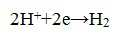
양극실(3)에 공급된 양극액은, 전해 처리된다. 즉 양극실(3)에는, 아염소산 이온(ClO2 -)과 양이온(아염소산염으로서 아염소산 나트륨을 사용한 경우는 나트륨이온)이 존재하기 때문에, 격막식 전해조(2)에 직류 전원 장치(도시하지 않음)에서 직류를 부하하면, 이하의 화학식 1에 도시한 바와 같이, 아염소산 이온이 양극에서 전자(e)를 방출하기 때문에, 이산화염소(ClO2)가 발생한다(양극 전해 공정). The anolyte supplied to the

한편, 양이온은 양이온 교환막(7)을 통과하여 음극실(5)로 들어간다. On the other hand, the cations pass through the cation exchange membrane 7 and enter the
상기 식 (1)에 의해 발생한 이산화염소는 그 높은 용해성에 의해 양극액 중에 용해되나, 폭기 수단(14)에 의해 불입된 폭기 기체에 의해 기액 평형 관계에 따라 액중 농도가 떨어지기 때문에 액외로 추출된다. 추출된 이산화염소는 공급된 폭기 기체에 의해 폭발 회피 가능한 농도(대략 10%v/v)보다도 더 낮은 농도로 희석되면서 채취관(15)으로 회수된다(폭기 공정). The chlorine dioxide generated by the above formula (1) is dissolved in the anolyte due to its high solubility, but is extracted out of the aqueous solution because the concentration in the solution falls due to the gas-liquid equilibrium relationship by the aeration gas charged by the aeration means . The extracted chlorine dioxide is recovered to the
양극실(3)에서 전해 처리된 후의 양극액은, 제1 연통로(P1)를 통해서 탈기조(9)에 이류한다. 탈기조(9)에 있어서도, 폭기 수단(14)에 의해 불입된 폭기 기체에 의해 다시 폭기 처리가 이루어지고, 양극액 중에 잔존하는 이산화염소가 액 외부로 추출된다. 추출된 이산화염소는, 양극실(3)과 탈기조(9)를 연통하는 제6 연통로(P6)를 통해서 다시 양극실(3)로 되돌아가고 채취관(15)으로 회수된다. 이 탈기조(9)에 있어서도, 추출된 이산화염소는, 폭기 기체에 의해, 폭발 회피 가능한 농도(대략 10%v/v)보다도 더 낮은 농도로 희석된다. The anolyte after electrolytic treatment in the anode chamber (3) flows to the degassing vessel (9) through the first communication path (P1). Also in the
또한, 본 실시예에서는, 양극실(3) 및 탈기조(9)로의 폭기 기체의 공급량을 조절 가능하게 구성함으로써, 이산화염소 농도를 컨트롤하고, 희석과 동시에 사용자의 소망하는 농도의 이산화염소를 제조하도록 구성하여도 된다. Further, in this embodiment, the supply amount of the aeration gas to the
탈기조(9)에서 폭기 처리된 후의 양극액은, 제2 연통로(P2)를 통해서 제1 배액조(10)에 이류한다. 그리고, 제1 배액조(10)에 이류한 양극액은, 제3 연통로(P3)를 통하고, 이번에는 음극액으로서, 격막식 전해조(2)의 음극실(5) 내에 공급된다. The anolyte after the aeration treatment in the
음극실(5)에서는, 음극액으로서 공급된 양극액 중에, 가령 이산화염소의 일부가, 양극실(3) 또는 탈기조(9)로 회수되지 않고 잔류하고 있을 경우, 그 잔류 이산화염소는, 음극실(5)의 음극(6)에 의해 음극 환원되어서 아염소산염이 된다. In the
또 음극실(5)에서는, 공급된 양극액(음극액)의 물의 일부가, 수소 이온(H+)과 수산화물 이온(OH-)으로 나누어져 있고, 이하의 화학식 2에 나타낸 바와 같이, 수소 이온이 음극(6)에서 전자를 얻어 수소 가스(H2)가 발생한다(음극 전해 공정). In the
한편, 남겨진 수산화물 이온은, 알칼리(예를 들면, 양이온이 나트륨 이온의 경우는, 수산화나트륨)가 된다. 따라서 음극실(5)에서 전해 처리된 후의 음극액은, 알칼리를 다량으로 포함하기 때문에 높은 pH를 가진다. 이 높은 pH를 가지는 음극액은, 중화 수단(12)에서 공급되는 중화제에 의해 중화된다(중화 공정). On the other hand, the hydroxide ions left are alkali (for example, sodium hydroxide in the case of a cation being a sodium ion). Therefore, the catholyte after electrolytic treatment in the
본 실시예에 있어서의 중화 수단(12)은, 음극실(5) 및 중화조(11)의 적어도 어느 한쪽에 중화제를 공급하도록 구성되어 있기 때문에, 높은 pH를 가지는 음극액은, 음극실(5) 및 중화조(11)의 적어도 어느 한쪽에서 중화된다. The neutralizing means 12 in the present embodiment is configured to supply the neutralizing agent to at least one of the
특히, 음극액이, 본 실시예의 중화조(11)에서 중화될 경우, 음극실(5)에서 전해 처리된 후의 높은 pH의 음극액이 제4 연통로(P4)를 통해서 중화조(11)에 이류하면, 폭기 수단(14)에 의해 취입되는 폭기 기체에 의해 중화 수단(12)에서 공급되는 중화제와 함께 격렬하게 교반·혼합되므로, 효율적인 중화 처리가 실시된다. Particularly, when the catholyte liquid is neutralized in the
중화조(11)에 공급된 폭기 기체는 그 후, 음극실(5)과 중화조(11)를 연통되는 제7 연통로(P7)를 통해서 음극실(5)로 이류한다. 이류한 폭기 기체는, 음극실(5)에서 발생한 수소 가스를 폭발 회피 가능한 농도(대략 4%v/v)보다도 더 낮은 농도로 희석하면서, 수소 가스와 함께 배기관(16)으로 배출된다. The aeration gas supplied to the
중화조(11)에서 중화 처리된 후의 음극액은, 제5 연통로(P5)를 통해서 제2 배액조(13)에 이류한다. 그리고, 제2 배액조(13)에 이류한 음극액은, 배액관(17)에서 장치 외부로 배출된다. The catholyte after the neutralization treatment in the
〔그 밖의 실시예〕 [Other Embodiments]
전술한 실시예의 격막식 전해조에 있어서, 양극실과 음극실을 구획하는 격막으로서 양이온 교환 막을 사용하고 있으나, 이것에 한정되는 것이 아니라, 중성 격막을 사용할 수도 있다. In the diaphragm electrolytic cell of the above-described embodiment, the cation exchange membrane is used as the diaphragm for partitioning the anode chamber and the cathode chamber, but not limited thereto, a neutral diaphragm may also be used.
실시예 Example
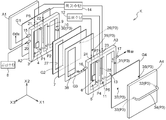
이하, 본 발명의 이산화염소 제조 장치에 적용되는 이산화염소 제조 키트(K)의 실시예를 도면에 의거하여 설명한다. 또한, 본 명세서 중에 있어서 「두께 방향」, 「높이 방향」, 「폭 방향」 각각은, 도 2에 있어서의 화살표 X1, X2, X3을 따르는 방향을 의미한다. Hereinafter, an embodiment of a chlorine dioxide manufacturing kit (K) applied to the chlorine dioxide producing apparatus of the present invention will be described with reference to the drawings. In the present specification, the terms "thickness direction", "height direction", and "width direction" refer to directions along arrows X1, X2, and X3 in FIG.
도 2에 도시한 바와 같이, 본 실시예에 의한 이산화염소 제조 키트(K)는, 제1~제4 부재(A1~A4), 제1~제4 개스킷 부재(G1~G4), 양이온 교환막(7) 및 도시하지 않은 외부 프레임 부재를 구비한다. 또한, 제1~제4 부재(A1~A4), 제1~제4 개스킷 부재(G1~G4) 및 양이온 교환막(7)은 모두 직사각형 부재이며, 이들의 폭과 높이는 동일 치수로 설정되어 있다. As shown in Fig. 2, the chlorine dioxide manufacturing kit K according to the present embodiment includes first to fourth members A1 to A4, first to fourth gasket members G1 to G4, a cation exchange membrane 7 and an outer frame member (not shown). The first to fourth members A1 to A4, the first to fourth gasket members G1 to G4, and the cation exchange membrane 7 are both rectangular members, and their width and height are set to the same dimension.
제1~제4 부재(A1~A4)는 모두 직사각형의 판형 부재로, 예를 들면, 폴리 염화비닐 등의 내구성 소재를 구성 소재로 한다. 또한, 제1 부재(A1) 및 제4 부재(A4) 각각의 두께는, 제2 부재(A2) 및 제3 부재(A3) 각각의 두께보다도 얇게 설정되어 있다. Each of the first to fourth members A1 to A4 is a rectangular plate member, and a durable material such as polyvinyl chloride is used as a constituent material. The thicknesses of the first member A1 and the fourth member A4 are set to be thinner than the thicknesses of the second member A2 and the third member A3, respectively.
도 2 및 도 3에 도시한 바와 같이, 제2 부재(A2)에는, 두께 방향으로 관통하는 직방체형의 3개의 관통 공간이 형성되어 있고, 이들 3개의 관통 공간 각각이, 양극실(3), 탈기조(9) 및 제1 배액조(10)를 구성한다. As shown in Figs. 2 and 3, in the second member A2, three through-holes of a rectangular parallelepiped shape penetrating in the thickness direction are formed, and each of these three through- The
양극(4)은, 제2 부재(A2)의 양극실(3) 안에 배치된다. The
제2 부재(A2)에 있어서의 양극실(3)측의 횡측벽에는, 양극실(3)의 이산화염소를 회수하기 위한 채취관(15) 및 공급 수단(8; 도 1 참조)에서 양극액을 양극실(3)로 도입하기 위한 양극액 도입관(20)이 설치되어 있다. 또한, 양극액 도입관(20)은, 채취관(15)의 하측에 설치된다. 1) for recovering the chlorine dioxide in the
폭기 수단(14; 도 1 참조)에서 폭기 기체를 양극실(3)에 도입하기 위한 제1 기체 도입관(21)이, 제2 부재(A2) 상측벽을 관통하여, 그 선단이 양극실(3)의 하부 공간으로 개구되게 설치되어 있다. The first
폭기 수단(14)에서 폭기 기체를 탈기조(9)에 도입하기 위한 제2 기체 도입관(22)이, 제2 부재(A2) 상측벽을 관통하여, 그 선단이, 탈기조(9)의 하부 공간으로 개구되게 설치되어 있다. The second
양극실(3)과 탈기조(9) 사이의 칸막이 벽의 상부 및 하부 각각에는, 양극실(3)과 탈기조(9)를 연통하는 제6 연통로(P6) 및 제1 연통로(P1)가 설치되어 있다. 또, 탈기조(9)와 제1 배액조(10) 사이의 칸막이 벽의 하부에는, 탈기조(9)와 제1 배액조(10)를 연통하는 제2 연통로(P2)가 설치되어 있다. A sixth communication path P6 and a first communication path P1 for communicating the
제2 부재(A2)에 있어서의 제1 배액조(10)측의 횡측벽에는, 제1 배액조(10)의 내벽면에서 제2 개스킷 부재(G2)와의 맞춤면에 통하는 L자형의 연통로(30)가 설치되어 있다. An L-shaped communication passage (10) communicating with the second gasket member (G2) is formed in the transverse side wall of the second member (A2) on the side of the first drainage tank (10) (30) is provided.
도 2 및 도 4에 도시한 바와 같이, 제3 부재(A3)에는, 두께 방향으로 관통하는 직방체형의 3개의 관통 공간이 형성되어 있고, 이들 3개의 관통 공간 각각이, 음극실(5), 중화조(11) 및 제2 배액조(13)를 구성한다. As shown in Figs. 2 and 4, the third member A3 is formed with three through-holes of a rectangular parallelepiped shape passing through in the thickness direction, and each of the three through- The
음극(6)은, 제3 부재(A3)의 음극실(5) 안에 배치된다. The
제3 부재(A3)에 있어서의 음극실(5)측의 횡측벽에는, 음극실(5)에서 발생한 수소 가스를 배출하기 위한 배기관(16)이 설치되어 있다. An
중화 수단(12)에서 중화제를 음극실(5)에 도입하기 위한 제1 중화제 도입관(24)이, 제3 부재(A3)의 상측벽을 관통하여, 그 선단이, 음극실(5)의 하부 공간으로 개구되게 설치되어 있다. The first neutralizing
폭기 수단(14)에서 폭기 기체를 중화조(11)에 도입하기 위한 제3 기체 도입관(23)과, 중화 수단(12; 도 1 참조)에서 중화제를 중화조(11)에 도입하기 위한 제2 중화제 도입관(25)이, 제3 부재(A3)의 상측벽을 관통하여, 각 선단이, 중화조(11)의 하부 공간으로 개구되게 설치되어 있다. A third
음극실(5)과 중화조(11) 사이의 칸막이 벽의 상부 및 하부 각각에는, 음극실(5)과 중화조(11)를 연통하는 제7 연통로(P7) 및 제4 연통로(P4)가 설치되어 있다. 또, 중화조(11)와 제2 배액조(13) 사이의 칸막이 벽의 하부에는, 중화조(11)와 제2 배액조(13)를 연통하는 제5 연통로(P5)가 설치되어 있다. A seventh communication path P7 and a fourth communication path P4 which communicate the
제3 부재(A3)에 있어서의 제2 배액조(13)측의 횡측벽에는, 제2 배액조(13)의 음극액을 장치 외부로 배출하기 위한 배액관(17)과, 두께 방향으로 관통하는 연통로(31)가 설치되어 있다. 또한, 연통로(31)는, 배액관(17)의 하측에 설치된다. The side wall of the third member A3 on the side of the
도 2에 도시한 바와 같이, 제4 부재(A4)는, 폭 방향의 양단부 각각에, 두께 방향으로 관통하는 관통공(32, 33)을 가지며, 이들 관통공(32, 33)이, ㄷ자형의 배관(34)을 개재하여 연통 접속되어 있다. As shown in Fig. 2, the fourth member A4 has through-
제1~제4 개스킷 부재(G1~G4)는, 예를 들면, 에틸렌-프로필렌-디엔고무(EPDM) 등의 내약품성 소재를 구성 소재로 하는, 모두 직사각형의 판형 부재이다. 제1~제4 개스킷 부재(G1~G4)에 의해, 이산화염소 제조 키트(K)에 높은 수밀성이 부여되고, 이산화염소 제조 키트(K)로부터의 액 누출이 방지된다. The first to fourth gasket members G1 to G4 are all rectangular plate members made of a chemical resistant material such as ethylene-propylene-diene rubber (EPDM) as a constituent material. The first to fourth gasket members (G1 to G4) impart high watertightness to the chlorine dioxide manufacturing kit (K) and prevent liquid leakage from the chlorine dioxide manufacturing kit (K).
도 2에 도시한 바와 같이, 제2 개스킷 부재(G2)는, 폭 방향의 일단부에서 두께 방향으로 관통하는 관통공(26)을 가지고, 타단부에서 두께 방향으로 관통하는 직방체형의 관통 공간(27)을 가진다. 또, 제3 개스킷 부재(G3)는 제2 개스킷 부재(G2)와 마찬가지로 폭 방향의 일단부에서 두께 방향으로 관통하는 관통공(35)을 가지고, 타단부에서 두께 방향으로 관통하는 직방체형의 관통 공간(38)을 가진다. 제2 개스킷 부재(G2)의 관통 공간(27)의 폭 및 높이는, 제2 부재(A2)의 양극실(3)의 폭 및 높이와 동일하거나, 또는 제2 부재(A2)의 양극실(3)의 폭 및 높이보다도 작게 설정하여도 되고, 또 제3 개스킷 부재(G3)의 관통 공간(38)의 폭 및 높이에 대해서도, 제3 부재(A3)의 음극실(5)의 폭 및 높이와 동일하거나, 또는 제3 부재(A3)의 음극실(5)의 폭 및 높이보다도 작게 설정하여도 된다. As shown in Fig. 2, the second gasket member G2 has a through-
제4 개스킷 부재(G4)는, 폭 방향의 양단부 각각에, 두께 방향으로 관통하는 관통공(36, 37)을 가진다. 또, 양이온 교환막(7)은, 폭 방향의 일단부에, 두께 방향으로 관통하는 도시하지 않은 관통공을 가진다. The fourth gasket member (G4) has through holes (36, 37) penetrating in the thickness direction at both end portions in the width direction. The cation exchange membrane 7 has through holes (not shown) penetrating in the thickness direction at one end in the width direction.
이산화염소 제조 키트(K)를 조립할 경우는, 제1~제4 부재(A1~A4), 제1~제4 개스킷 부재(G1~G4) 및 양이온 교환막(7)을 도 2에 나타낸 바와 같이 배치한다. 다시 말해, 제1 부재(A1)와 제2 부재(A2)의 사이에 제1 개스킷 부재(G1)를 배치하고, 제2 부재(A2)와 제3 부재(A3)의 사이에 제2 개스킷 부재(G2), 양이온 교환막(7) 및 제3 개스킷 부재(G3)를 이 순서로 배치하고, 제3 부재(A3)와 제4 부재(A4)의 사이에 제4 개스킷 부재(G4)를 배치한다. When the chlorine dioxide manufacturing kit K is assembled, the first to fourth members A1 to A4, the first to fourth gasket members G1 to G4, and the cation exchange membrane 7 are arranged as shown in Fig. 2 do. In other words, a first gasket member G1 is disposed between the first member A1 and the second member A2, and a second gasket member G1 is provided between the second member A2 and the third member A3. The cation exchange membrane 7 and the third gasket member G3 are disposed in this order and the fourth gasket member G4 is disposed between the third member A3 and the fourth member A4 .
이때, 제2 개스킷 부재(G2)를, 그 관통 공간(27)이 제2 부재(A2)의 양극실(3)에 대향하게 배치하고, 제3 개스킷 부재(G3)를, 그 관통 공간(38)이 제3 부재(A3)의 음극실(5)에 대향하게 배치한다. 또, 제4 개스킷 부재(G4)를, 그 한쪽의 관통공(36)이 제3 부재(A3)의 연통로(31)에 대향하고, 다른 쪽의 관통공(37)이 제3 부재(A3)의 음극실(5)에 대향하게 배치한다. 또, 제4 부재(A4)를, 이 2개의 관통공(32, 33) 각각이 제4 개스킷 부재(G4)의 2개의 관통공(36, 37)에 대향하게 배치한다. At this time, the second gasket member G2 is disposed so that its through
도 2와 같이 배치한 제1~제4 부재(A1~A4), 제1~제4 개스킷 부재(G1~G4) 및 양이온 교환막(7)의 각각의 끝을 맞추면서, 서로 밀착되게 한 상태에서, 도시하지 않은 외부 프레임 부재에 끼워 넣음으로써, 직방체형 또는 입방체형의 이산화염소 제조 키트(K)가 완성된다. In a state in which the ends of the first to fourth members A1 to A4, the first to fourth gasket members G1 to G4, and the cation exchange membrane 7 arranged as shown in Fig. 2 are brought into close contact with each other, Is inserted into an outer frame member (not shown), whereby a rectangular or cubic chlorine dioxide manufacturing kit K is completed.
이산화염소 제조 키트(K)의 내부에서는, 제2 부재(A2)의 연통로(30), 제2 개스킷 부재(G2)의 관통공(26), 양이온 교환막(7)의 관통공(도시하지 않음), 제3 개스킷 부재(G3)의 관통공(35), 제3 부재(A3)의 연통로(31), 제4 개스킷 부재(G4)의 한쪽의 관통공(36), 제4 부재(A4)의 한쪽의 관통공(32), 배관(34), 제4 부재(A4)의 다른 쪽의 관통공(33), 및 제4 개스킷 부재(G4)의 다른 쪽의 관통공(37)이 연통된다. 이에 의해, 제2 부재(A2)의 제1 배액조(10)에서 제3 부재(A3)의 음극실(5)에 걸쳐서 연통되는 제3 연통로(P3)가 형성된다. In the inside of the chlorine dioxide manufacturing kit K, the
또, 제2 부재(A2)의 양극실(3)과 제2 개스킷 부재(G2)의 관통 공간(27)이 연통되고, 제3 부재(A3)의 음극실(5)과 제3 개스킷 부재(G3)의 관통 공간(38)이 연통되기 때문에, 제2 부재(A2)의 양극실(3)과 제3 부재(A3)의 음극실(5)이 양이온 교환막(7)을 개재하여 상대 배치되어, 격막식 전해조(2)가 형성된다. The
다시 말해, 상기 이산화염소 제조 키트(K)에서는, 격막식 전해조(2), 유로부(C), 및 배출부(D)가 일체화되어 있다. 따라서, 이 이산화염소 제조 키트(K)를 사용함으로써, 이산화염소 제조 장치의 구성을 컴팩트화 할 수 있다. In other words, in the chlorine dioxide manufacturing kit K, the diaphragm type
이어서, 상기 구성의 이산화염소 제조 키트(K)를 사용하여 이산화염소를 제조하였다. Then, chlorine dioxide was prepared using the chlorine dioxide manufacturing kit (K) having the above-described structure.
전극 치수가 폭 18mm, 높이 46mm, 두께 1mm의 양극(4) 및 음극(5)을 구비한, 폭 73mm, 높이 148mm, 두께 45mm의 이산화염소 제조 키트(K)를 제작하였다. 그리고 상기 이산화염소 제조 키트(K)의 제1 및 제2 기체 도입관(21, 22)에 폭기 수단(14)을 접속하고, 이산화염소 제조 키트(K)의 양극액 도입관(20)에 공급 수단(8)을 접속하고, 이산화염소 제조 키트(K)의 제2 중화제 도입관(25)에 중화 수단(12)을 접속하여 이산화염소 제조 장치(1)를 구성하였다. A chlorine dioxide production kit K having a width of 73 mm, a height of 148 mm and a thickness of 45 mm and having an
25중량%의 아염소산나트륨 800mL과 염화칼륨 50g을 물에 용해하여 1L로 하여, 양극액을 조제하였다. 이 양극액을 공급 수단(8)의 송액 펌프에 의해 14mL/시간으로 송액하였다. 800 ml of 25% by weight sodium chlorite and 50 g of potassium chloride were dissolved in water to make 1 L, thereby preparing an anolyte. This anolyte was fed by a feeding pump of the feeding means 8 at 14 mL / hour.
또, 인산 2수소 칼륨 200g과 인산 1수소 칼륨 100g을 물에 용해하여 1L로 하여, 중화제를 조제하였다. 이 중화제를 중화 수단(12)의 송액 펌프에 의해 14mL/시간으로 송액하였다. Further, 200 g of potassium dihydrogenphosphate and 100 g of potassium monohydrogenphosphate were dissolved in water to make 1 L, and a neutralizing agent was prepared. This neutralizing agent was fed at a rate of 14 mL / hour by the feed pump of the neutralization means 12.
그리고, 양극(4) 및 음극(6)에 대하여 800mA로 통전하고, 또한, 양극실(3)과 탈기조(9)에 대하여 폭기 수단(14)의 폭기 펌프에 의해 공기를 공급하고, 채취관(15)에서 방출된 이산화염소를 요오드화 칼륨 용액으로 소정시간 흡수하고, 유리된 요소를 소정의 치오황산나트륨 수용액으로 적정(滴定)하였다. 그 결과, 1.2g/시간 이산화염소가 발생하고 있었던 것이 확인되었다. 또, 배액관(17)에서 배출된 배액에는, 거의 이산화염소가 포함되지 않고, pH도 7.8이며, 안전하게 폐기하는 것이 가능하였다. Air was supplied to the
본 발명에 의한 이산화염소 제조 장치 및 이산화염소 제조 방법은, 이산화염소에 의한 환경살균이나 소취 등에 관한 산업분야에 적합하게 이용할 수 있다. The apparatus for producing chlorine dioxide and the method for producing chlorine dioxide according to the present invention can be suitably used in industrial fields related to environmental sterilization and deodorization by chlorine dioxide.
1 : 이산화염소 제조 장치
2 : 격막식 전해조
3 : 양극실
4 : 양극
5 : 음극실
6 : 음극
7 : 양이온 교환막
8 : 공급 수단
9 : 탈기조
10 : 제1 배액조
11 : 중화조
12 : 중화 수단
13 : 제2 배액조
14 : 폭기 수단
15 : 채취관
16 : 배기관
17 : 배액관
P1~P7 : 제1~제7 연통로
C : 유로부
D : 배출부 1: Chlorine dioxide production equipment
2: Membrane electrolytic cell
3: anode chamber
4: anode
5: cathode chamber
6: cathode
7: Cation exchange membrane
8: Supply means
9:
10: First drainage tank
11: neutralization tank
12: Neutralizing means
13: Second drainage tank
14: aeration means
15: Collecting tube
16: Exhaust pipe
17: Drain tube
P1 to P7: first to seventh communication passages
C:
D:
Claims (5)
상기 양극실과 상기 음극실을 연통하는 유로부와,
상기 음극실과 외부를 연통하는 배출부와,
공급량 조절 가능하게 폭기 기체를 상기 양극실에 공급하는 폭기 수단과,
상기 음극실 및 상기 배출부의 적어도 어느 한쪽에 중화제를 공급하는 중화 수단을 구비하고,
상기 양극실에 있어서 상기 양극액을 전해 처리하여 이산화염소를 발생하게 하고,
상기 폭기 수단에 의해 폭기 기체를 상기 양극실의 양극액에 공급함으로써, 발생한 이산화염소를 회수하고,
상기 양극실에서 전해 처리 및 폭기 처리된 후의 양극액이, 상기 유로부를 통하여 상기 음극실에 이류하여 음극액으로서 전해 처리된 후, 상기 음극실 및 상기 배출부의 적어도 어느 한쪽에서 중화 처리되도록 구성되는 이산화염소 제조 장치. A diaphragm type electrolytic cell having an anode chamber and a cathode chamber, electrolytically treating an anode liquid containing chlorosalt supplied to the anode chamber to generate chlorine dioxide,
A channel portion communicating the anode chamber and the cathode chamber,
A discharge portion communicating with the cathode chamber and the outside,
An aeration means for supplying an aeration gas to the anode chamber so as to control the supply amount,
And neutralizing means for supplying a neutralizing agent to at least one of the cathode chamber and the discharge portion,
Electrolytically treating the anolyte in the anode chamber to generate chlorine dioxide,
And an aeration gas is supplied to the anolyte of the anode chamber by the aeration means to recover the generated chlorine dioxide,
Wherein the anode liquid after the electrolytic treatment and the aeration treatment in the anode chamber is electrolytically treated as a catholyte by passing through the channel portion to the cathode chamber and then neutralized in at least one of the cathode chamber and the discharge portion, Chlorine production equipment.
상기 격막식 전해조의 양극실에 아염소산염을 포함하는 양극액을 공급하는 공급 공정과,
상기 양극액을 전해 처리하여 이산화염소를 발생하게 하는 양극 전해 공정과,
폭기 기체를 상기 양극실의 양극액에 공급함으로써, 발생한 이산화염소를 회수하는 폭기 공정과,
상기 양극실에서 전해 처리 및 폭기 처리된 후의 양극액을, 음극액으로 하여 상기 음극실에서 전해 처리하는 음극 전해 공정과,
상기 음극실에서 전해 처리된 후의 음극액을 배출하는 배출 공정과,
상기 음극 전해 공정 및 상기 배출 공정의 적어도 어느 한쪽에 있어서 음극액을 중화 처리하는 중화 공정을 포함하는 이산화염소 제조 방법. A method for producing chlorine dioxide using a diaphragm type electrolytic cell having an anode chamber and a cathode chamber,
A supply step of supplying an anolyte solution containing chlorate to the anode chamber of the diaphragm electrolytic cell,
A cathodic electrolytic process for electrolyzing the anolyte to generate chlorine dioxide;
An aeration step of supplying the anolyte of the anode chamber with an aeration gas to recover the generated chlorine dioxide,
A negative electrode electrolytic process for electrolytically treating the anolyte after the electrolytic treatment and the aeration treatment in the anode chamber as a catholyte in the negative electrode chamber;
A discharging step of discharging the catholyte after electrolytic treatment in the cathode chamber;
And a neutralization step of neutralizing the catholyte in at least one of the catholyte electrolysis process and the discharge process.
Applications Claiming Priority (3)
| Application Number | Priority Date | Filing Date | Title |
|---|---|---|---|
| JP2013186366 | 2013-09-09 | ||
| JPJP-P-2013-186366 | 2013-09-09 | ||
| PCT/JP2014/072910 WO2015033887A1 (en) | 2013-09-09 | 2014-09-01 | Chlorine dioxide production device and chlorine dioxide production method |
Publications (1)
| Publication Number | Publication Date |
|---|---|
| KR20160054471A true KR20160054471A (en) | 2016-05-16 |
Family
ID=52628361
Family Applications (1)
| Application Number | Title | Priority Date | Filing Date |
|---|---|---|---|
| KR1020167005801A KR20160054471A (en) | 2013-09-09 | 2014-09-01 | Chlorine dioxide production device and chlorine dioxide production method |
Country Status (8)
| Country | Link |
|---|---|
| US (1) | US10094029B2 (en) |
| EP (1) | EP3045568A4 (en) |
| JP (1) | JP6448540B2 (en) |
| KR (1) | KR20160054471A (en) |
| CN (1) | CN105683417B (en) |
| HK (2) | HK1225418B (en) |
| TW (1) | TWI646223B (en) |
| WO (1) | WO2015033887A1 (en) |
Families Citing this family (5)
| Publication number | Priority date | Publication date | Assignee | Title |
|---|---|---|---|---|
| CL2014003049A1 (en) * | 2014-11-10 | 2015-05-29 | Propipe Maquinarias Limitada | Multi-purpose electrolytic device for forced or spontaneous processes of electro-obtaining metals with independent electrolytes, which allows the electrolytic transformation of ions in a controlled manner, with high efficiency of pharadic current and with high energy efficiency; process. |
| TWI611050B (en) * | 2016-04-27 | 2018-01-11 | Liu De Hui | Auxiliary device and system for stably producing high-purity food grade chlorine dioxide |
| CN109642334B (en) * | 2016-09-05 | 2020-12-08 | 株式会社大阪曹达 | Chlorine dioxide generator and chlorine dioxide generating method |
| CN111621803A (en) * | 2020-06-05 | 2020-09-04 | 池晓雷 | Chlorine dioxide generating device and application |
| CN114921799A (en) * | 2022-05-11 | 2022-08-19 | 上海交通大学 | Method and device for simultaneously synthesizing high-purity chlorine dioxide gas by using single-atom cathode and anode |
Family Cites Families (8)
| Publication number | Priority date | Publication date | Assignee | Title |
|---|---|---|---|---|
| US2163793A (en) * | 1937-06-08 | 1939-06-27 | Mathieson Alkall Works Inc | Production of chlorine dioxide |
| JPS596915B2 (en) | 1980-05-13 | 1984-02-15 | 日本カ−リツト株式会社 | Electrolytic production method of chlorine dioxide |
| JPH02205693A (en) | 1989-02-03 | 1990-08-15 | Japan Carlit Co Ltd:The | Method and apparatus for producing chlorine dioxide by electrolysis |
| US5158658A (en) | 1990-10-31 | 1992-10-27 | Olin Corporation | Electrochemical chlorine dioxide generator |
| JP3849725B2 (en) * | 1996-04-11 | 2006-11-22 | 水道機工株式会社 | Chlorine dioxide production method |
| US7754057B2 (en) * | 2004-07-29 | 2010-07-13 | Pureline Treatment Systems, Llc | Chlorine dioxide solution generator |
| WO2009154143A1 (en) * | 2008-06-19 | 2009-12-23 | 大幸薬品株式会社 | Method for producing chlorine dioxide with single-liquid electrolysis |
| CN102812160B (en) * | 2010-03-19 | 2015-06-03 | 大幸药品株式会社 | Electrolyzer |
-
2014
- 2014-09-01 KR KR1020167005801A patent/KR20160054471A/en active Search and Examination
- 2014-09-01 JP JP2015535457A patent/JP6448540B2/en active Active
- 2014-09-01 WO PCT/JP2014/072910 patent/WO2015033887A1/en active Application Filing
- 2014-09-01 US US14/911,931 patent/US10094029B2/en not_active Expired - Fee Related
- 2014-09-01 CN CN201480049450.8A patent/CN105683417B/en not_active Expired - Fee Related
- 2014-09-01 EP EP14843084.6A patent/EP3045568A4/en not_active Withdrawn
- 2014-09-05 TW TW103130819A patent/TWI646223B/en not_active IP Right Cessation
-
2016
- 2016-12-05 HK HK16113830A patent/HK1225418B/en not_active IP Right Cessation
- 2016-12-26 HK HK16114707A patent/HK1226451A1/en unknown
Also Published As
| Publication number | Publication date |
|---|---|
| EP3045568A4 (en) | 2017-04-12 |
| TW201606137A (en) | 2016-02-16 |
| HK1225418B (en) | 2017-09-08 |
| EP3045568A1 (en) | 2016-07-20 |
| HK1226451A1 (en) | 2017-09-29 |
| JP6448540B2 (en) | 2019-01-09 |
| US10094029B2 (en) | 2018-10-09 |
| CN105683417A (en) | 2016-06-15 |
| CN105683417B (en) | 2018-04-10 |
| WO2015033887A1 (en) | 2015-03-12 |
| JPWO2015033887A1 (en) | 2017-03-02 |
| US20160201203A1 (en) | 2016-07-14 |
| TWI646223B (en) | 2019-01-01 |
Similar Documents
| Publication | Publication Date | Title |
|---|---|---|
| US6274009B1 (en) | Generator for generating chlorine dioxide under vacuum eduction in a single pass | |
| JP2627100B2 (en) | Method and apparatus for producing sterilized water | |
| WO2017030153A1 (en) | Electrolysis apparatus and electrolysis method | |
| JPS58224189A (en) | Chlorine gas generator and method | |
| KR20160054471A (en) | Chlorine dioxide production device and chlorine dioxide production method | |
| WO1998058880A1 (en) | Method and apparatus for the electrochemical treatment of water and aqueous salt solutions | |
| US20010022273A1 (en) | Electrochemical treatment of water and aqueous salt solutions | |
| JP4929430B2 (en) | Electrolyzed water production apparatus and electrolyzed water production method | |
| KR101269948B1 (en) | Apparatus and method for nitrogen wastewater treatment | |
| KR101436139B1 (en) | A electrolysis apparatus | |
| JP4705190B1 (en) | Electrolyzed water production apparatus and production method thereof | |
| JP4685838B2 (en) | Electrolyzed water production apparatus, electrolyzed water production method, and electrolyzed water | |
| US20140318981A1 (en) | Method, apparatus, and system for electro-chemical activation of water | |
| JP3746932B2 (en) | Electrolyzed water generator | |
| JP2000005757A (en) | Economical production of electrolytic sterilizing water | |
| JP4620720B2 (en) | Electrolyzed water production apparatus, electrolyzed water production method, and electrolyzed water | |
| JP4685830B2 (en) | Electrolyzed water production apparatus, electrolyzed water production method, and electrolyzed water | |
| JP4348195B2 (en) | Method and apparatus for treating chlorine gas generated by diaphragm electrolysis | |
| JP3893693B2 (en) | Electrolyzed water production equipment | |
| EP2872677B1 (en) | Electrolytic cell with catholyte recycle | |
| JP3568290B2 (en) | Electrolyzed water generator | |
| KR100523982B1 (en) | Electrolytic disinfectants generator | |
| US20200232104A1 (en) | Device Comprising a Channel, a Cathode, an Anode and a Power Source, and Method for the Production of Chlorine Dioxide | |
| JP2023089991A (en) | Hypocrite water supply apparatus and space sterilization system using the same | |
| JP2001122601A (en) | Method and device for producing hydrogen peroxide |
Legal Events
| Date | Code | Title | Description |
|---|---|---|---|
| A201 | Request for examination |