KR20160051882A - Battery thermal management systems, apparatuses, and methods - Google Patents
Battery thermal management systems, apparatuses, and methods Download PDFInfo
- Publication number
- KR20160051882A KR20160051882A KR1020167008965A KR20167008965A KR20160051882A KR 20160051882 A KR20160051882 A KR 20160051882A KR 1020167008965 A KR1020167008965 A KR 1020167008965A KR 20167008965 A KR20167008965 A KR 20167008965A KR 20160051882 A KR20160051882 A KR 20160051882A
- Authority
- KR
- South Korea
- Prior art keywords
- mini
- battery
- fluid
- channel
- temperature
- Prior art date
Links
Images


Classifications
-
- H—ELECTRICITY
- H01—ELECTRIC ELEMENTS
- H01M—PROCESSES OR MEANS, e.g. BATTERIES, FOR THE DIRECT CONVERSION OF CHEMICAL ENERGY INTO ELECTRICAL ENERGY
- H01M10/00—Secondary cells; Manufacture thereof
- H01M10/60—Heating or cooling; Temperature control
- H01M10/65—Means for temperature control structurally associated with the cells
- H01M10/655—Solid structures for heat exchange or heat conduction
- H01M10/6556—Solid parts with flow channel passages or pipes for heat exchange
-
- F—MECHANICAL ENGINEERING; LIGHTING; HEATING; WEAPONS; BLASTING
- F28—HEAT EXCHANGE IN GENERAL
- F28F—DETAILS OF HEAT-EXCHANGE AND HEAT-TRANSFER APPARATUS, OF GENERAL APPLICATION
- F28F1/00—Tubular elements; Assemblies of tubular elements
-
- F—MECHANICAL ENGINEERING; LIGHTING; HEATING; WEAPONS; BLASTING
- F28—HEAT EXCHANGE IN GENERAL
- F28F—DETAILS OF HEAT-EXCHANGE AND HEAT-TRANSFER APPARATUS, OF GENERAL APPLICATION
- F28F1/00—Tubular elements; Assemblies of tubular elements
- F28F1/02—Tubular elements of cross-section which is non-circular
- F28F1/022—Tubular elements of cross-section which is non-circular with multiple channels
-
- H—ELECTRICITY
- H01—ELECTRIC ELEMENTS
- H01M—PROCESSES OR MEANS, e.g. BATTERIES, FOR THE DIRECT CONVERSION OF CHEMICAL ENERGY INTO ELECTRICAL ENERGY
- H01M10/00—Secondary cells; Manufacture thereof
- H01M10/42—Methods or arrangements for servicing or maintenance of secondary cells or secondary half-cells
- H01M10/48—Accumulators combined with arrangements for measuring, testing or indicating the condition of cells, e.g. the level or density of the electrolyte
- H01M10/486—Accumulators combined with arrangements for measuring, testing or indicating the condition of cells, e.g. the level or density of the electrolyte for measuring temperature
-
- H—ELECTRICITY
- H01—ELECTRIC ELEMENTS
- H01M—PROCESSES OR MEANS, e.g. BATTERIES, FOR THE DIRECT CONVERSION OF CHEMICAL ENERGY INTO ELECTRICAL ENERGY
- H01M10/00—Secondary cells; Manufacture thereof
- H01M10/60—Heating or cooling; Temperature control
- H01M10/61—Types of temperature control
- H01M10/613—Cooling or keeping cold
-
- H—ELECTRICITY
- H01—ELECTRIC ELEMENTS
- H01M—PROCESSES OR MEANS, e.g. BATTERIES, FOR THE DIRECT CONVERSION OF CHEMICAL ENERGY INTO ELECTRICAL ENERGY
- H01M10/00—Secondary cells; Manufacture thereof
- H01M10/60—Heating or cooling; Temperature control
- H01M10/61—Types of temperature control
- H01M10/615—Heating or keeping warm
-
- H—ELECTRICITY
- H01—ELECTRIC ELEMENTS
- H01M—PROCESSES OR MEANS, e.g. BATTERIES, FOR THE DIRECT CONVERSION OF CHEMICAL ENERGY INTO ELECTRICAL ENERGY
- H01M10/00—Secondary cells; Manufacture thereof
- H01M10/60—Heating or cooling; Temperature control
- H01M10/62—Heating or cooling; Temperature control specially adapted for specific applications
- H01M10/625—Vehicles
-
- H—ELECTRICITY
- H01—ELECTRIC ELEMENTS
- H01M—PROCESSES OR MEANS, e.g. BATTERIES, FOR THE DIRECT CONVERSION OF CHEMICAL ENERGY INTO ELECTRICAL ENERGY
- H01M10/00—Secondary cells; Manufacture thereof
- H01M10/60—Heating or cooling; Temperature control
- H01M10/63—Control systems
-
- H—ELECTRICITY
- H01—ELECTRIC ELEMENTS
- H01M—PROCESSES OR MEANS, e.g. BATTERIES, FOR THE DIRECT CONVERSION OF CHEMICAL ENERGY INTO ELECTRICAL ENERGY
- H01M10/00—Secondary cells; Manufacture thereof
- H01M10/60—Heating or cooling; Temperature control
- H01M10/65—Means for temperature control structurally associated with the cells
- H01M10/654—Means for temperature control structurally associated with the cells located inside the innermost case of the cells, e.g. mandrels, electrodes or electrolytes
-
- H—ELECTRICITY
- H01—ELECTRIC ELEMENTS
- H01M—PROCESSES OR MEANS, e.g. BATTERIES, FOR THE DIRECT CONVERSION OF CHEMICAL ENERGY INTO ELECTRICAL ENERGY
- H01M10/00—Secondary cells; Manufacture thereof
- H01M10/60—Heating or cooling; Temperature control
- H01M10/65—Means for temperature control structurally associated with the cells
- H01M10/655—Solid structures for heat exchange or heat conduction
- H01M10/6556—Solid parts with flow channel passages or pipes for heat exchange
- H01M10/6557—Solid parts with flow channel passages or pipes for heat exchange arranged between the cells
-
- H—ELECTRICITY
- H01—ELECTRIC ELEMENTS
- H01M—PROCESSES OR MEANS, e.g. BATTERIES, FOR THE DIRECT CONVERSION OF CHEMICAL ENERGY INTO ELECTRICAL ENERGY
- H01M10/00—Secondary cells; Manufacture thereof
- H01M10/60—Heating or cooling; Temperature control
- H01M10/65—Means for temperature control structurally associated with the cells
- H01M10/656—Means for temperature control structurally associated with the cells characterised by the type of heat-exchange fluid
- H01M10/6567—Liquids
- H01M10/6568—Liquids characterised by flow circuits, e.g. loops, located externally to the cells or cell casings
-
- F—MECHANICAL ENGINEERING; LIGHTING; HEATING; WEAPONS; BLASTING
- F28—HEAT EXCHANGE IN GENERAL
- F28D—HEAT-EXCHANGE APPARATUS, NOT PROVIDED FOR IN ANOTHER SUBCLASS, IN WHICH THE HEAT-EXCHANGE MEDIA DO NOT COME INTO DIRECT CONTACT
- F28D21/00—Heat-exchange apparatus not covered by any of the groups F28D1/00 - F28D20/00
- F28D2021/0019—Other heat exchangers for particular applications; Heat exchange systems not otherwise provided for
- F28D2021/0043—Other heat exchangers for particular applications; Heat exchange systems not otherwise provided for for fuel cells
-
- F—MECHANICAL ENGINEERING; LIGHTING; HEATING; WEAPONS; BLASTING
- F28—HEAT EXCHANGE IN GENERAL
- F28F—DETAILS OF HEAT-EXCHANGE AND HEAT-TRANSFER APPARATUS, OF GENERAL APPLICATION
- F28F2260/00—Heat exchangers or heat exchange elements having special size, e.g. microstructures
- F28F2260/02—Heat exchangers or heat exchange elements having special size, e.g. microstructures having microchannels
-
- H—ELECTRICITY
- H01—ELECTRIC ELEMENTS
- H01M—PROCESSES OR MEANS, e.g. BATTERIES, FOR THE DIRECT CONVERSION OF CHEMICAL ENERGY INTO ELECTRICAL ENERGY
- H01M10/00—Secondary cells; Manufacture thereof
- H01M10/60—Heating or cooling; Temperature control
- H01M10/64—Heating or cooling; Temperature control characterised by the shape of the cells
- H01M10/647—Prismatic or flat cells, e.g. pouch cells
-
- H—ELECTRICITY
- H01—ELECTRIC ELEMENTS
- H01M—PROCESSES OR MEANS, e.g. BATTERIES, FOR THE DIRECT CONVERSION OF CHEMICAL ENERGY INTO ELECTRICAL ENERGY
- H01M2220/00—Batteries for particular applications
- H01M2220/20—Batteries in motive systems, e.g. vehicle, ship, plane
-
- Y—GENERAL TAGGING OF NEW TECHNOLOGICAL DEVELOPMENTS; GENERAL TAGGING OF CROSS-SECTIONAL TECHNOLOGIES SPANNING OVER SEVERAL SECTIONS OF THE IPC; TECHNICAL SUBJECTS COVERED BY FORMER USPC CROSS-REFERENCE ART COLLECTIONS [XRACs] AND DIGESTS
- Y02—TECHNOLOGIES OR APPLICATIONS FOR MITIGATION OR ADAPTATION AGAINST CLIMATE CHANGE
- Y02E—REDUCTION OF GREENHOUSE GAS [GHG] EMISSIONS, RELATED TO ENERGY GENERATION, TRANSMISSION OR DISTRIBUTION
- Y02E60/00—Enabling technologies; Technologies with a potential or indirect contribution to GHG emissions mitigation
- Y02E60/10—Energy storage using batteries
-
- Y02E60/122—
-
- Y—GENERAL TAGGING OF NEW TECHNOLOGICAL DEVELOPMENTS; GENERAL TAGGING OF CROSS-SECTIONAL TECHNOLOGIES SPANNING OVER SEVERAL SECTIONS OF THE IPC; TECHNICAL SUBJECTS COVERED BY FORMER USPC CROSS-REFERENCE ART COLLECTIONS [XRACs] AND DIGESTS
- Y02—TECHNOLOGIES OR APPLICATIONS FOR MITIGATION OR ADAPTATION AGAINST CLIMATE CHANGE
- Y02T—CLIMATE CHANGE MITIGATION TECHNOLOGIES RELATED TO TRANSPORTATION
- Y02T10/00—Road transport of goods or passengers
- Y02T10/60—Other road transportation technologies with climate change mitigation effect
- Y02T10/70—Energy storage systems for electromobility, e.g. batteries
-
- Y02T10/7011—
Abstract
본 명세서에서 일반적으로 논의되는 것은 배터리 열 관리(BTM) 장치, 시스템, 방법이다. BTM 장치는 하나 이상의 배터리 전지, 및 하나 이상의 배터리 전지를 사전 결정되는 온도 범위 내에 유지하기 위해 하나 이상의 배터리 전지와 열적으로 접촉시키도록 하나 이상의 배터리 전지에 부착되는 하나 이상의 미니채널 튜브를 포함할 수 있다. A battery thermal management (BTM) device, system, and method are generally discussed herein. The BTM device may include one or more battery cells, and one or more mini-channel tubes attached to the one or more battery cells to thermally contact one or more battery cells to maintain the one or more battery cells within a predetermined temperature range .
Description
본 출원은 그 전체가 참조에 의해 본 명세서에 포함되는 "미니채널 기술에 기초한 배터리 열관리 시스템"이라는 명칭의 미국 가특허출원 번호 61/875,222의 우선권을 주장한다.This application claims priority to U.S. Provisional Patent Application No. 61 / 875,222 entitled " Battery Thermal Management System Based on Mini-Channel Technology ", which is incorporated herein by reference in its entirety.
배터리 열관리 시스템(BTMS)은 다양한 작동 조건 하에서 높은 성능을 달성하기 위한, 그리고/또는 차량 안정을 유지하기 위한 전기 자동차(EV)의 중요한 컴포넌트 중 하나이다. EV는 배터리 EV(BEV) 또는 하이브리드 EV(HEV)(예를 들면, 플러그-인 또는 논-플러그-인 HEV)를 포함할 수 있다.A battery thermal management system (BTMS) is one of the key components of an electric vehicle (EV) to achieve high performance under various operating conditions and / or to maintain vehicle stability. The EV may include a battery EV (BEV) or a hybrid EV (HEV) (e.g., a plug-in or non-plug-in HEV).
EV는 가스, 디젤, 또는 기타 연료를 동력원으로 하는 차량에 비해 배출이 감소된다. 일부의 EV는 심지어 제로(zero) 배기를 포함할 수 있고, 에너지 또는 온실효과가스 배출 목표를 달성하는데 중요한 역할을 할 수 있다. EV는 또한 개선된 에너지 안전, 개선된 환경 및 공중 보건의 질, 개선된 연료주입 비용 및 유지관리 비용을 포함하는 기타의 이익을 제공할 수 있다.EVs reduce emissions compared to vehicles powered by gas, diesel, or other fuels. Some EVs can even include zero emissions and can play an important role in achieving energy or greenhouse gas emissions targets. EVs can also provide other benefits, including improved energy security, improved environmental and public health quality, improved fuel injection costs, and maintenance costs.
첨부된 다양한 도면은 본 명세서에 제공된 요지의 실시형태를 예시한다. 첨부된 도면은 당업자가 본 명세서에 개시된 개념을 이해할 수 있도록 제공된 것이므로 개시된 요지의 범위를 제한하는 것으로 간주될 수 없다.The accompanying drawings illustrate embodiments of the subject matter provided herein. The accompanying drawings are provided to enable any person of ordinary skill in the art to understand the concepts disclosed herein, and therefore can not be considered as limiting the scope of the disclosed subject matter.
도 1은 60 퍼센트 충전상태(SOC)에서 Li-Mn 배터리 캘린더 수명 대 온도의 그래프를 도시한다.
도 2는 다양한 온도에서 측정된 흑연-LiFePO4 배터리 퍼센트 용량 손실 대 총 암페어 시 처리능력/암페어시의 그래프를 도시한다.
도 3은 종래기술의 배터리 냉각 시스템의 블록도를 도시한다.
도 4는 하나 이상의 실시형태에 따른 미니채널(minichannel) 튜브의 실시예의 블록도를 도시한다.
도 5는 하나 이상의 실시형태에 따른 미니채널 튜브의 단부도를 도시한다.
도 6a는 열전달 계수 대 포트의 폭의 그래프를 도시한다.
도 6b는 압력 강하 대 포트의 폭의 그래프를 도시한다.
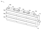
도 7은 하나 이상의 실시형태에 따른 배터리 열관리 BTM 장치의 일 실시예의 블록도를 도시한다.
도 8은 하나 이상의 실시형태에 따른 다른 BTM 장치의 다른 실시예의 블록도를 도시한다.
도 9는 하나 이상의 실시형태에 따른 다른 BTM 장치의 다른 실시예의 블록도를 도시한다.
도 10은 하나 이상의 실시형태에 따른 다른 BTM 장치의 일 실시예의 블록도를 도시한다.
도 11a는 하나 이상의 실시형태에 따른 배터리 전지의 일 실시예의 블록도를 도시한다.
도 11b는 하나 이상의 실시형태에 따른 다른 배터리 전지의 일 실시예의 블록도를 도시한다.
도 12는 하나 이상의 실시형태에 따른 BTMS의 일 실시예의 블록도를 도시한다.
도 13은 하나 이상의 실시형태에 따른 BTMS의 다른 실시예의 블록도를 도시한다.
도 14a는 하나 이상의 실시형태에 따른 미니채널 튜브를 포함하는 전지의 시뮬레이션된 열 다이어그램을 도시한다.
도 14b는 하나 이상의 실시형태에 따른 미니채널 튜브의 연부 및 연부의 근처의 온도 기울기의 시뮬레이션된 열 다이어그램을 도시한다.
도 15는 하나 이상의 실시형태에 따른 BTMS의 사용 방법의 일 실시예의 흐름도를 도시한다.Figure 1 shows a graph of Li-Mn battery calender life vs. temperature at 60 percent state of charge (SOC).
Figure 2 illustrates a graphite -LiFePO 4 percent battery capacity loss for the graph of the total capacity in processing capability / ampere-hour measured at various temperatures.
Figure 3 shows a block diagram of a prior art battery cooling system.
4 shows a block diagram of an embodiment of a minichannel tube according to one or more embodiments.
Figure 5 shows an end view of a mini-channel tube according to one or more embodiments.
Figure 6a shows a graph of heat transfer coefficient versus port width.
6B shows a graph of pressure drop vs. port width.
FIG. 7 illustrates a block diagram of one embodiment of a battery thermal management BTM device in accordance with one or more embodiments.
8 shows a block diagram of another embodiment of another BTM device according to one or more embodiments.
9 shows a block diagram of another embodiment of another BTM device according to one or more embodiments.
10 shows a block diagram of one embodiment of another BTM device according to one or more embodiments.
11A shows a block diagram of one embodiment of a battery cell according to one or more embodiments.
11B shows a block diagram of one embodiment of another battery cell according to one or more embodiments.
12 shows a block diagram of one embodiment of a BTMS according to one or more embodiments.
13 shows a block diagram of another embodiment of a BTMS according to one or more embodiments.
14A shows a simulated thermal diagram of a cell including a mini-channel tube according to one or more embodiments.
Figure 14B shows a simulated thermal diagram of the temperature gradient near the edges and edges of the mini-channel tube according to one or more embodiments.
15 shows a flow diagram of one embodiment of a method of using a BTMS according to one or more embodiments.
이하의 설명은 본 명세서에 기재된 요지의 다양한 양태를 구체화하는 예시적인 장치, 시스템, 방법, 및 기법을 포함한다. 이하의 설명에서, 설명의 목적을 위해, 많은 구체적인 세부내용이 요지의 다양한 실시형태의 이해를 제공하기 위해 설명된다. 그러나, 본 기술분야의 당업자에게는 이 요지의 실시형태가 이들 구체적인 세부내용의 적어도 일부를 포함하지 않고 실시될 수 있다는 것이 명백할 것이다. The following description includes exemplary apparatus, systems, methods, and techniques embodying various aspects of the subject matter described herein. In the following description, for purposes of explanation, numerous specific details are set forth in order to provide an understanding of the various embodiments of the subject matter. It will be apparent, however, to one skilled in the art that the embodiments of the subject matter may be practiced without including at least some of these specific details.
본 개시는 일반적으로 배터리 열관리(BTM)의 분야, 더 구체적으로는 BTMS 내에 하나 이상 미니채널을 포함하는 것과 관련되는 시스템, 장치, 및 방법에 관한 것이다.The present disclosure relates generally to the field of battery thermal management (BTM), and more particularly to systems, apparatus, and methods associated with including one or more mini-channels within a BTMS.
수송 분야의 에너지 소비는 모든 온실효과 가스(GHG) 배기의 거의 40% 및 캘리포니아의 모든 대기 오염의 50% 이상을 초래한다. 캘리포니아 대기 자원 위원회에 따르면, EV는 종래의 차량에 비해 풀 퓨얼 사이클(full fuel cycle)의 배기가 65% 내지 70% 더 낮다(조사 당시의 캘리포니아의 전력 공급망에 기초함). 따라서, EV는 캘리포니아 경제 및 기후 안정화의 성공에 유망한, 그리고 잠재적으로 획기적인 필수수단이다. 비싸지 않은 견고하고 신뢰성 있는 EV 배터리를 위한 지속적인 개발 노력은 광범위한 EV 채택을 크게 가속화시킬 수 있고, 이것은 캘리포니아 뿐만 아니라 세계의 기타 지역에 개선된 에너지 안전, 개선된 환경 및 공중 보건의 질, 감소된 자동차 연료주입 및 유지관리 비용, 및 재생가능한/그린 에너지 및 자동차 산업에서 캘리포니아의 주도적 역할을 강화하는 것을 포함하는 상당한 이익을 제공할 수 있다. 유사한 이익이 다른 지역에서 실현될 수 있고, 캘리포니아는 단지 본 명세서에서 논의되는 EV 및 요지가 반향을 가질 수 있는 편리한 예시적 지역으로서 사용된다.Energy consumption in the transportation sector results in nearly 40% of all greenhouse gas (GHG) emissions and more than 50% of all air pollution in California. According to the California Air Resources Board, EVs are 65% to 70% lower (based on California's electricity supply chain at the time of the survey) of full fuel cycle emissions compared to conventional vehicles. Thus, EV is a promising and potentially revolutionary essential to the success of the California economy and climate stabilization. Continuous development efforts for inexpensive, rugged and reliable EV batteries can greatly accelerate the adoption of a wide range of EVs, which will enable improved energy security, improved environmental and public health quality in California as well as other parts of the world, Fuel injection and maintenance costs, and renewable / green energy and California's leadership role in the automotive industry. Similar benefits can be realized in other areas, and California is used only as a convenient exemplary area where EVs and considerations discussed in this specification can have repercussions.
전술한 것에 불구하고, EV의 광범위한 채택에 직면하는 적어도 2 개의 문제가 있다. 1) 배터리 팩의 높은 비용 및 2) 제한된 품질보증을 갖는 짧은 배터리 수명(예를 들면, 약 8 년). 전기 팬을 구비하는 공냉 시스템, 물, 글리콜, 오일, 아세톤, 및 냉매를 구비하는 액체 냉각 시스템, 및 상변화 물질(PCM) 냉각 시스템과 같은 EV 배터리용 일부의 또는 전부의 종래의 냉각 시스템이 연구되었고, 이들의 성능이 재검토되었다. 본 명세서에서 논의되는 바와 같이, 본 명세서에서 논의되는 BTM 시스템, 장치, 및 방법 중 하나 이상은 온도 조절 일관성, 비용, 또는 출력 효율의 면에서 종래의 냉각 시스템보다 성능이 뛰어날 수 있다. Notwithstanding the foregoing, there are at least two problems faced by the widespread adoption of EVs. 1) high cost of the battery pack and 2) short battery life with limited warranty (eg, about 8 years). Some or all of the conventional cooling systems for EV batteries, such as air cooling systems with electric fans, liquid cooling systems with water, glycols, oils, acetone, and refrigerants, and phase change material (PCM) And their performance was reviewed. As discussed herein, one or more of the BTM systems, apparatuses, and methods discussed herein may outperform conventional cooling systems in terms of temperature control consistency, cost, or output efficiency.
다양한 배터리 제조사 및 차량 개발사는 열관리를 위해 다양한 전략을 채택해왔다. 냉각 매체의 경우, 공기 및 액체 냉매의 양자 모두가 사용된다. 더 단순한 공냉식 시스템이 액체 냉각보다 비용이 다소 더 낮다는 것은 일반적으로 받아들여진다. 그러나, 액체 냉각은 공냉 보다 출력 및 온도 조절의 면에서 일반적으로 더 효율적이다. 예를 들면, 2012 년에, 더 더운 기후에서 닛산 리프(Nissan Leaf) 고객에 의해 보고된 하나 이상의 바의 배터리 용량 손실의 112 건의 확인된 사례가 있다(주로 미국의 애리조나, 텍사스 및 캘리포니아에서). 배터리 용량 손실은 불충분한 공냉이 원인으로 생각되었다. EV 배터리의 경우, 능동적인 유체에 기초한 시스템은 미국 남부에서 여름에 종종 겪게 되는 조건과 같은 좀 더 극단적인 온도 조건 하에서 배터리 성능(예를 들면, 수명 및 용량)을 개선하기 위해 유익하다. 이러한 종류의 조건에 처리하기 위해, BTM 유닛은 약 -30 ℃ 내지 약 50 ℃ 사이의 온도와 같은 넓은 온도 범위를 처리할 수 있어야 한다. Various battery manufacturers and vehicle developers have adopted various strategies for heat management. In the case of a cooling medium, both air and liquid refrigerant are used. It is generally accepted that simpler air-cooled systems are somewhat lower in cost than liquid cooling. However, liquid cooling is generally more efficient in terms of power and temperature regulation than air cooling. For example, in 2012 there are 112 confirmed cases of battery capacity loss of more than one bar reported by Nissan Leaf customers in hotter climates (mainly in Arizona, Texas and California in the United States). The battery capacity loss was thought to be due to insufficient air cooling. For EV batteries, active fluid-based systems are beneficial for improving battery performance (e.g., life and capacity) under more extreme temperature conditions, such as those often encountered in the summer of the United States. To handle this kind of condition, the BTM unit must be able to handle a wide temperature range, such as a temperature between about -30 캜 and about 50 캜.
리튬-이온(Li-이온) 배터리는 다른 배터리 유형에 비해 비교적 높은 출력 및 에너지 밀도, 뿐만 아니라 높은 전력 방전을 제공한다. Li-이온 배터리의 이러한 능력으로 인해 이것은 EV 용의 유망한 후보가 된다. 그러나, 배터리 수명의 증가를 위해, Li-이온 배터리의 온도는, 예를 들면, 배터리 수명 또는 성능을 증가시키는 것을 도와 주는 특정의 온도 범위(예를 들면, 약 20 ℃ 내지 약 30 ℃의 범위) 내에 유지되는 것으로부터 이익을 얻을 수 있다. 배터리는 심지어 배터리로부터 전혀 전력이 인출되지 않는 경우에도 특정의 온도 범위 내에 유지되는 것으로부터 이익을 얻을 수 있다.Lithium-ion (Li-ion) batteries offer relatively high power and energy density, as well as high power discharge, compared to other battery types. This ability of the Li-ion battery makes it a promising candidate for the EV. However, for increased battery life, the temperature of the Li-ion battery can be adjusted to a specific temperature range (e.g., in the range of about 20 ° C to about 30 ° C) to help increase battery life or performance, ≪ / RTI > The battery can benefit from being kept within a certain temperature range even when no power is drawn from the battery.
배터리의 수명의 종료(EOL)는 전형적으로 약 20% 용량 손실 또는 약 30% 내부 저항에 도달된 때로 정의된다. EV 배터리의 용량은 배터리의 내부 저항이 경시적으로 증가함에 따라 경시적으로 감소된다. 일반적으로 이러한 경향은 배터리가 사용 중이거나 또는 사용되지 않고 보관 중이거나 무관하다. 이러한 상태는, 대응하는 배터리 수명이 대체로 캘린더 수명과 관련되므로, 일반적으로 "캘린더 페이드(calendars fade)"라 부른다. 도 1은 60% 충전상태(SOC)에서 리튬-망가니즈(Li-Mn) 배터리 캘린더 수명 대 온도를 위한 곡선을 갖는 전형적인 그래프(100)를 도시한다. Li-Mn 배터리는 22 ℃에서 (예를 들면, 평균으로) 8년을 약간 초과하는 수명을 갖지만, 32 ℃에서는 불과 5년의 수명을 갖는다. 만일 경시적으로 이 평균 SOC가 60% SOC를 초과한다면, 캘린더 수명은 도 1에 도시된 것보다 작을 수 있다. 다른 유형의 Li-이온 배터리의 배터리 수명 대 온도의 경우에도 유사한 경향이 있다. SOC는 가솔린 차량의 연료계처럼 최대량(100 퍼센트)에 대해 얼마나 많은 양의 연료가 주입될 수 있는지를 나타낸다. 따라서, 60% SOC는 60%의 최대 총 배터리 충전이 가능함을 나타낸다.The end of life (EOL) of the battery is typically defined as about 20% capacity loss or about 30% internal resistance. The capacity of the EV battery decreases with time as the internal resistance of the battery increases over time. Generally, this tendency is irrelevant whether the battery is in use or not being used or being stored. This condition is commonly referred to as a "calendars fade" since the corresponding battery life is generally related to the life of the calendar. Figure 1 shows an
배터리는 또한 사용에 따라 열화되고, 이것은 "사이클 페이드(cycle fade)"로 알려져 있다. 대응하는 수명은 배터리의 사이클 수명이다. 도 2는 흑연-LiFePO4 배터리 사이클 수명의 예측치를 3 개의 상이한 온도에서의 실험 데이터와 비교한 그래프(200)를 도시한다: 15 ℃, 45 ℃ 및 60 ℃. 이 그래프(200)는 온도의 증가와 함께 배터리 용량 손실이 증가하는 것(또는 사이클 수명이 감소하는 것)을 도시한다.The battery also deteriorates with use, which is known as a "cycle fade ". The corresponding lifetime is the cycle life of the battery. Figure 2 shows a
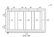
도 3은 팩 레벨에서 종래의 액체 냉각을 구비하는 전지 모듈 및 팩을 포함하는 종래기술의 배터리 냉각 시스템(300)을 예시한다.전지(302A, 302B, 302C, 302D)의 모듈 내의 측면에는 알루미늄 전도 채널(304A, 304B, 304C, 304D, 304E)이 설치되어 있고, 이것에 의해 분리된다. 알루미늄 전도 채널(304A-E)은 전지의 측면으로부터 열의 배출을 촉진시킨다. 전지(302A-D)와 팩 재킷(306) 사이의 간극은 전지(302A-D)의 측면으로부터 배터리(300)를 냉각시키거나 또는 가열시키는 쿨런트(coolant)를 위한 통로(308)를 형성한다. 화살표는 통로(308)의 내외로 쿨런트의 유동을 나타낸다. 일반적으로 에틸렌-글리콜/물(EG/W) 용액이 이 배터리 팩(300)을 위한 쿨런트로서 사용된다. 이러한 유형의 설계의 경우, 전지(302A-D)는 기밀하게 실링된 모듈 내에 수용되고, 쿨런트의 유동을 봉쇄하고, 쿨런트가 모듈의 말단이나 또는 그 상호접속부와 접촉하는 것을 방지하기 위해 폴리머 실링재가 상이한 모듈들 사이에 사용된다. 그렇지 않으면, EG/W 용액의 누출은 전지(302A-D)를 단락시킬 수 있고, 잠재적으로 위험을 초래할 수 있다.Figure 3 illustrates a prior art
도 3에 도시된 것과 같은 종래의 BTM의 경우에는 본 명세서에서 논의되는 BTM의 설계 시에 고려되는 적어도 4 가지 문제가 있다: 1) 팩 레벨에서 설계된 BTMS는 불균일한 온도 분포를 초래할 수 있다(약 10 ℃ 이상의 온도 분포가 팩의 단일의 전지 내에서 경험될 수 있다); 2) 배터리 팩의 국부적인 노후화; 3) 모듈 및 팩 재킷의 기밀 설계는 높은 재료 비용 또는 제조 비용을 초래한다; 4) 종래의 액체 도관 설계는 BTMS의 중량 및 콤팩트하지 않은 체적의 증가를 초래한다. In the case of a conventional BTM as shown in Fig. 3, there are at least four problems that are considered in the design of the BTM discussed herein: 1) BTMS designed at the pack level can result in a non-uniform temperature distribution A temperature distribution of 10 DEG C or higher can be experienced in a single cell of the pack); 2) local aging of the battery pack; 3) The tight design of the module and pack jacket results in high material costs or manufacturing costs; 4) Conventional liquid conduit designs result in an increase in the weight and non-compact volume of the BTMS.
논의된 하나 이상의 단점을 극복하기 위해, 미니채널 튜브(예를 들면, 마이크로채널 튜브)를 포함하는 배터리가 제안된다. 도 4는 하나 이상의 실시형태에 따른 다양한 미니채널 튜브 구성(400)의 일 실시예를 도시한다. 미니채널 튜브(402A, 402B, 402C, 402D, 402E, 402F, 402G, 402H, 402I, 402J)는, 예를 들면, 수십 마이크로미터 내지 수십 밀리미터의 범위의 포트의 폭 또는 수력학 내경을 갖는 단일의 포트 튜브 또는 다중포트 튜브이다. 많은 미니채널은 0.2 밀리미터 내지 약 3 밀리미터의 수력학 직경을 포함한다.이 미니채널 튜브(402A-J)는 다양한 포트 형상 및 크기를 포함할 수 있다. 미니채널 튜브(402A-J)는 대체로 직사각형, 타원형, 또는 대체로 정사각형 또는 원형의 모서리 또는 측면을 포함할 수 있는 기타 형상의 포트를 포함할 수 있다. 포트는 난류를 감소시키거나 또는 층류를 도와줄 수 있는 돌출부를 포함할 수 있다. 미니채널 튜브에 관한 더 상세한 내용은 도 5에 관련하여 그리고 본 명세서의 다른 부분에서 논의된다. In order to overcome one or more of the disadvantages discussed, a battery comprising a mini-channel tube (e.g., a microchannel tube) is proposed. FIG. 4 illustrates one embodiment of various
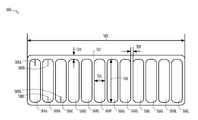
도 5는 하나 이상의 실시형태에 따른 미니채널 튜브(500)의 일 실시예의 단부도를 도시한다. 미니채널 튜브(500)는 하나 이상의 포트(504A, 504B, 504C, 504D, 504E, 504F, 504G, 504H, 504I, 504J, 504K, 또는 504L)를 포함할 수 있다. 이 포트(504A-L)는 포트(504A-L)의 내부로 연장되는 돌출부(506A, 506B, 506C, 또는 506D)를 포함할 수 있다. 도 5는 포트(504A-C) 내에 최대 2 개의 돌출부(506B-C)를 도시하고, 대체로 직선형으로 이 돌출부(506A-D)부를 도시하고 있으나, 본 명세서에 제공된 상세한 설명을 읽고 이해한 당업자는 상이한 크기, 형상 및 수의 돌출부를 포트(504A-L) 내에 사용할 수 있다는 것을 인식할 것이다. 돌출부(506A-D)의 수 및 형상은 유체가 관련된 포트(504A-L) 내에서 더 적은 난류를 갖는 유체(예를 들면, 액체 또는 기체)를 포함하도록 도와주도록 구성될 수 있다.FIG. 5 illustrates an end view of one embodiment of a
미니채널 튜브(500)는 열전도율 성능, 및 미니채널 튜브(500)가 견딜 수 있는 최대 압력을 결정하는 것에 관련될 수 있는 치수를 포함할 수 있다. 이 치수는 전체 폭(502)(W), 포트들 사이의 간격(508)(Ww), 측벽(512)의 두께(510)(Wt), 포트(504A-K)의 폭(514)(Wc), 및 포트(504A-K)의 높이(516)(Hc)를 포함할 수 있다. 하나 이상의 실시형태에서, 폭(514)은 약 수십 마이크로미터 내지 약 수십 밀리미터일 수 있다. 하나 이상의 실시형태에서, 폭(614)은 약 0.2 밀리미터 내지 약 3 밀리미터일 수 있다. 측벽 두께(512)는 열전도율의 감소를 희생으로 더 높은 압력에서 견딜 수 있는 더 두꺼운 측벽을 갖는 다양한 두께일 수 있다. 하나 이상의 실시형태에서, 측벽(512)의 두께는 약 100 마이크로미터 내지 약 200 마이크로미터일 수 있다. The
포트(504A-K) 내의 유체 압력 또는 열전도율 요건과 같은 요인에 따라, 측벽 두께(510), 또는 포트 간격(508)이 결정될 수 있다. 더 얇은 측벽 두께(510)는 열전달(예를 들면, 열전도율)을 개선할 수 있다. 더 두꺼운 측벽 두께(510) 또는 포트 간격(508)은 미니채널 튜브(500)가 더 높은 유체 압력에 견딜 수 있도록 도와줄 수 있다. 미니채널 튜브(500)는 일반적으로 높은 열효율(높은 열전도율), 낮은 재료 비용 및 중량, 및 콤팩트한 설계를 갖는다. 미니채널 설계에서 다른 고려사항은 포트(504A-K) 내의 압력을 감소시키는 증가된 포트의 폭(514)을 포함할 수 있다. Depending on factors such as fluid pressure or thermal conductivity requirements within
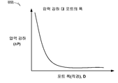
도 6a는 열전달 계수(h) 대 포트의 폭(514)의 그래프(600A)를 도시한다. 그래프(600A)에 도시된 바와 같이, 포트(504A-K)의 열전달 계수(열전도율)는 포트의 폭(514)이 증가함에 따라 감소한다. 도 6b는 압력 강하(ΔP) 대 포트의 폭(514)의 그래프(600B)를 도시한다. 그래프(600B)에 도시된 바와 같이, 압력 강하는 포트의 폭(514)이 감소함에 따라 감소한다.6A shows a
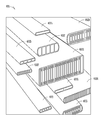
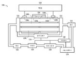
도 7 및 도 8은 하나 이상의 실시형태에 따른 BTM 시스템(700, 800)의 일부의 실시예를 도시한다. 다양한 실시형태에서, 미니채널 튜브(708A, 708B, 708C)은 팩 레벨(예를 들면, 도 3에 도시된 바와 같은 냉각 시스템)에 비해 전지 레벨(무엇보다도 도 7 및 도 8에 도시된 바와 같음)에서 냉각/가열되는 BTMS에서 사용될 수 있다. 이 BTM 시스템(700)은 배터리 커넥터(704A, 704B)를 통해 직렬로 결합되는 하나 이상의 배터리 전지(702A, 702B, 또는 702C)를 포함할 수 있다. 시스템(700)은 이 시스템(700)의 전기 에너지에 접근하기 위한 단자를 포함할 수 있다. Figures 7 and 8 illustrate an embodiment of a portion of a
하나 이상의 미니채널 튜브(708A, 708B, 또는 708C)는 전지(702A-C) 중 어느 하나 이상에 열적으로 결합될 수 있다. 미니채널 튜브(708A-C)는 폴리머, 플라스틱, 탄소, 알루미늄 또는 다른 금속, 또는 이들의 조합을 포함하는 다양한 재료를 사용하여 형성될 수 있다. 하나 이상의 실시형태에서, 미니채널 튜브(708A-C)는 전지(702A-C)의 주위에 꼭맞게 끼워맞춤되도록 형성될 수 있다. 하나 이상의 실시형태에서, 미니채널 튜브(708A-C)는 전지(702A-C)에 연납땜, 용접, 접착, 또는 아니면 부착될 수 있다. 미니채널 튜브(708A-C)는, 하나 이상의 실시형태에서, 평평한 알루미늄 다중포트 미니채널 튜브(FAMMT)을 포함할 수 있다. 도 7의 미니채널 튜브(708A-C)는 대체로 "U자" 형상(도 7의 평면도로 보았을 때)이고, 전지(702A-C)의 적어도 2 개의 측면과 접촉(예를 들면, 열적으로 결합)된다.One or more
예를 들면, 미니채널 튜브(708A-C)의 일부와 대응하는 전지(702A-C) 사이에 간극이 존재하는 위치의 열 그리스 또는 소결된 금속은 미니채널 튜브(708A-C)와 전지(702A-C) 사이에 열적 접속을 증가시키는 것을 도와 줄 수 있다. For example, thermal grease or sintered metal in a location where a gap exists between a portion of the
미니채널 튜브(708A-C)의 각각은 유입 포트(710) 및 유출 포트(712)에 결합될 수 있다. 유입 포트(710)는 유체를 포트(710) 및 미니채널 튜브(708A-C)를 통해 가압할 수 있는 펌프(도 7 및 도 8에 도시되지 않고, 도 12 및 도 13을 참조할 것)에 결합될 수 있다. 유출 포트(712)는 미니채널 튜브(708A-C)로부터 멀어지는 방향으로 유체를 운반하는 것을 도와줄 수 있다. Each of the
BTMS에서 하나 이상의 미니채널 튜브(708A-C)를 사용하는 것의 일부의 장점은 (a) 미니채널을 이용하여 열효율을 향상시키고; (b) 전지의 레벨에서 더욱 효율적인 냉각을 통해 배터리 팩 내에서 불균일한 온도 분포를 감소시키고; (c) 도 3에 도시된 것과 같은 시스템을 사용할 때 요구될 수 있는 바와 같은 전지 모듈 및 팩 재킷의 고가의 설계 및 제조의 기밀성 제약을 제거하고; (d) 도 3에 도시된 바와 같은 종래기술의 알루미늄 전도 채널을 제거하고; (e) 배터리 팩 및 BTMS의 전체 설계를 단순화하고; (f) 전체 팩 중량 및 체적을 감소시키고; (g) 배터리 및/또는 BTMS의 제조 비용을 감소시키는 것을 포함할 수 있다. Some advantages of using one or more
전술한 장점에 더하여, 미니채널 튜브를 포함하는 BTMS의 쿨런트 유체는 미니채널 유체 시스템(예를 들면, 유입 포트(들)(710), 유입 튜브(들)(814)(도 8 참조), 미니채널 튜브(708A-C), 유출 포트(들)(712-C), 및 유출 튜브(816)(도 8 참조) 중 어느 하나 이상의 조합) 내에 수용될 수 있고, 이것은 쿨런트가 전지 단자 및 그 상호연결부에 접촉하는 것을 감소시킬 뿐만 아니라 전지 접속부의 설계를 단순화시킨다. 그러나, 비록 누출 고려사항이 고려된다 하더라도, 비도전성 유체가 미니채널 튜브(708A-C)에서 사용될 수 있다. 예를 들면, 미네랄 오일, 변압기유, 다양한 냉매 등과 같은 특정의 열전도성 유체가 채용될 수 있다. 더욱이, 유체 금속과 같은 다른 열전도성 매체도 또한 미니채널 튜브(500) 내의 유체로서 사용될 수 있다. 하나 이상의 실시형태에서, 열전도성 기체가 미니채널 튜브 내의 쿨런트로서 채용될 수 있다.In addition to the advantages described above, the coolant fluid of the BTMS, including the mini-channel tube, can be introduced into a mini channel fluid system (e.g., inlet port (s) 710, inlet tube (s) 814 A combination of any one or more of the
또한, 다른 유형의 미니채널 튜브도 마찬가지로 채용될 수 있다. 예를 들면, 우수한 열전도율(예를 들면, 약 알루미늄의 열전도율 이상의 열전도율)을 갖는 기타 재료가 미니채널 튜브를 제작하기 위해 사용될 수 있다. 이러한 재료는, 예를 들면, 구리, 청동, 및 기타 철 이외의 재료 및 철 재료, 탄소-함침된 폴리머 또는 다른 열전도성 플라스틱 등을 포함할 수 있다. 그러나, 이해의 용이성 및 간결성을 위해, 본 명세서에서 채용되는 정확한 재료 또는 기하학적 형상은 시판되는 미니채널 튜브에서 발견되는 것과 동일하거나 또는 상이할 수 있다는 이해 하에서 본 명세서에서 미니채널 튜브가 사용된다In addition, other types of mini-channel tubes may be employed as well. For example, other materials having an excellent thermal conductivity (for example, a thermal conductivity equal to or higher than the thermal conductivity of weak aluminum) may be used to fabricate mini-channel tubes. Such materials may include, for example, materials other than copper, bronze, and other ferrous materials, carbon-impregnated polymers or other thermally conductive plastics, and the like. However, for ease of understanding and simplicity, mini-channel tubes are used herein, with the understanding that the exact material or geometry employed herein may be the same as or different from those found in commercially available mini-channel tubes
도 7에 도시된 바와 같이, 미니채널 튜브(708A-C)는 전지(702A-C)를 따르는 하나 이상의 다중의 위치에서 전지(702A-C)와 열적인 근접 상태로 위치될 수 있다. 다양한 실시형태에서, 미니채널 튜브(708A-C)는 미니채널 튜브(708A-C)의 형상에 기계적으로 정밀하게 일치되도록 형성될 수 있다. 다른 실시형태에서, 미니채널 튜브(708A-C)는, 예를 들면, 유해한 압력 강하를 방지하는 것을 도와주기 위해, 또는 미니채널 튜브 내의 유체의 층류를 유지하는 것을 도와 주기 위해 전지(702A-C)의 특정의 기하학적 형상에 관하여 증가된 반경을 갖도록 형성될 수 있다.As shown in FIG. 7, the
또한, 다양한 실시형태에서, 미니채널 튜브(708A-C)를 전지(702A-C)에의 결합부의 열전도성은 경납땜, 용접, 연납땜, 또는 미니채널 튜브(708A-C)과 전지(702A-C) 사이의 일부의 다른 부착 메커니즘을 통해 개선될 수 있다. 다양한 실시형태에서, 미니채널 튜브(708A-C)와 전지(702A-C) 사이의 열 계면은 다양한 유형의 열전도성 접착제, 그리스, 금속 소결, 에폭시 또는 이들의 조합의 사용을 통해 개선될 수 있다. In addition, in various embodiments, the thermal conductivities of the joining portions of the
일반적으로, 전지(702A-C)의 내부에서 발생되는 열은 전도를 통해 미니채널 튜브(708A-C)로 전달되고, 다음에 유체 대류를 통해 발산된다. 열 발산율은 전지(702A-C)의 감지된 온도를 제어 신호로서 사용하여 폐루프 제어 시스템에 의해 제어될 수 있는 유체의 유량에 직접적으로 의존된다. 폐루프 제어 시스템은 본 기술분야에서 독립적으로 공지되어 있는 폐루프 제어 개념에 기초하여 당업자가 이해하는 것이다. Generally, the heat generated within the
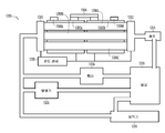
도 8은 하나의 팩으로 (직렬로) 결합된 복수의 열의 전지(802A-F)를 구비한 시스템(700)과 유사한 시스템(800)을 도시하고, 한편 도 7은 하나의 팩을 형성하도록 결합된 단일의 열의 전지(702A-C)를 도시한다. 전지(802A, 802B, 802C, 802D, 802E, 802F, 802I, 802J, 802K, 802L, 802M, 802N, 802O)는 전지(702A-C)와 실질적으로 동일할 수 있고, 이것은 커넥터(704A-B)와 실질적으로 유사할 수 있는 배터리 커넥터(804A, 804B, 804C, 804D, 804E, 804F, 804G, 804H, 804I, 804J, 804K, 804L, 804M, 또는 804N)를 통해 직렬로 결합될 수 있다. 시스템(800)은 단자(706A-B)와 유사한 시스템(800A-B)의 전기 에너지에 접근하기 위한 단자(806A, 806B)를 포함할 수 있다. 도 8에 도시된 바와 같이, 유입 포트(810A, 810B, 810C)는 공통의 유입 튜브(814)에 결합될 수 있고, 유출 포트(812A, 812B, 812C)는 공통의 유출 튜브(816)에 결합될 수 있다. 본 명세서에서 사용될 때, "실질적으로 동일"은 제품이 이것과 실질적으로 동일한 제품과 동일하거나 또는 유사한 재료로 제조될 수 있음을 의미한다. 시스템(800)의 미니채널 튜브(808A-C)는 인접하는 열의 전지와 접촉될 수 있다(예를 들면, 전지(802A-C 및 802D-F)는 독립된 열의 전지이고, 서로 인접될 수 있다). 상기 열의 전지(802A-C)의 상기 열의 전지(802D-F)는 동시에 열적으로 결합되도록(예를 들면, 열적 접촉 상태로) 구성될 수 있다. FIG. 8 shows a
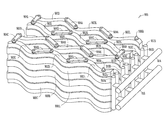
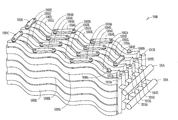
도 9 및 도 10은 각각 하나 이상의 실시형태에 따른 BTM 시스템(900, 1000)의 일부의 실시예를 도시한다. 전지(902A, 902B, 902C, 902D, 902E, 902F, 902G, 902H, 902J, 902K, 902L) 및 전지(1002A, 1002B, 1002C, 1002D, 1002E, 1002F, 1002G, 1002H, 1002J, 1002K, 1002L)는 전지(702A-C)와 실질적으로 동일할 수 있고, 전지(902A-L) 및 전지(1002A-L)는 불규칙한 형상을 포함한다. 미니채널 튜브(908A, 908B, 908C, 1008A, 1008B, 1008C)은 미니채널 튜브(708A-C)와 실질적으로 동일할 수 있고, 미니채널 튜브(908A-C) 및 미니채널 튜브(1008A-C)는 각각 전지(902A-L) 및 전지(1002A-L)의 외형을 따르는 형상을 포함한다. 이들 도는 미니채널 튜브(708A-C, 808A-C, 908A-C, 1008A-C)가 비표준 전지 상에서 사용될 수 있고, 광범위한 전지 형상에 적합될 수 있다는 것을 입증하기 위한 것이다. 일부의 미니채널 튜브 형상은, 예를 들면, 효율을 저하시키고, 심지어 실행을 불가능하게 하는 튜브 내에서의 압력 강하 또는 난류와 같은 문제를 일으킬 수 있다.Figures 9 and 10 illustrate an embodiment of a portion of a
커넥터(904A, 904B, 904C, 904D, 904E, 904F, 904G, 904H, 904I, 904J, 904K, 1004A, 1004B, 1004C, 1004D, 1004E, 1004F, 1004G, 1004H, 1004I, 1004J, 1004K)는 커넥터(704A-B)와 실질적으로 동일할 수 있고; 단자(906A, 906B, 1006A, 1006B)는 단자(706A-B)와 실질적으로 동일할 수 있고; 유입 포트(910A, 910B, 910C, 910D, 1010A, 1010B, 1010C, 1010D)는 유입 포트(710)와 실질적으로 동일할 수 있고; 유출 포트(912A, 912B, 912C, 912D, 1012A, 1012B, 1012C, 1012D)는 유출 포트(712)와 실질적으로 동일할 수 있고; 유입 튜브(914, 1014)는 유입 튜브(814)와 실질적으로 동일할 수 있고; 유출 튜브(916, 1016)는 유출 튜브(816)와 실질적으로 동일할 수 있다. 포트(910A-D, 912A-D, 1010A-D, 1012A-D) 및 튜브(914, 916, 1014, 1016)는 미니채널 튜브(708A-C)와 동일한 재료를 포함할 수 있고, 또한 다른 재료를 포함할 수도 있다. 포트(710, 712, 810A-C, 812A-C, 910A-D, 912A-D, 1010A-D, 1012A-D), 또는 튜브(914, 916, 1014, 1016)는, 예를 들면, 내부의 유체의 온도가 일정하게 유지되는 것을 도와 주도록 절연될 수 있다.The
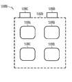
도 11a는 하나 이상의 실시형태에 따른 배터리(1100A)의 일 실시예를 도시한다. 배터리(1100A)는 하나 이상의 리세스(1104A, 1104B, 1104C, 1104D, 1104E, 1104F) 및 하나 이상의 단자(1106A, 1106B)를 포함하는 전지(1102A)를 포함할 수 있다. 미니채널 튜브(708A-C, 808A-C, 908A-C, 또는 1008A-C)는 적어도 부분적으로 리세스(1104A-F) 내로 슬롯을 구비할 수 있다. 리세스(1104A-F) 내에 튜브(708A-C, 808A-C, 908A-C, 또는 1008A-C)에 슬롯을 형성함으로써, 튜브(808A-C, 908A-C, 또는 1008A-C)는 전지(1102A)와 접촉하는 더 큰 표면적을 가질 수 있고, 따라서, 더 효율적인 가열 또는 냉각을 제공할 수 있다. 도 11a는 직사각형 형상을 포함하는 것으로 리세스(1104A-F)를 도시하고 있으나, 리세스(1104A-F)는 특히 타원, 원형의 모서리 형상, 다각형, 불규칙한 형상, 또는 이들의 조합과 같은 다른 형상을 포함할 수 있다11A illustrates one embodiment of a
도 11b는 하나 이상의 실시형태에 따른 배터리(1100B)의 일 실시예를 도시한다. 이 배터리(1100B)는 전지(1102B)의 내부에 하나 이상의 미니채널 튜브(1108A, 1108B, 1108C, 또는 1108D) 및 하나 이상의 단자(1106A, 1106B)를 포함하는 전지(1102B)를 포함할 수 있다. 미니채널 튜브(1108A-D)는 전지(1102B)의 전해질과 접촉될 수 있다(이 전해질은 도의 불명료함을 방지하도록 도시되지 않음). 미니채널 튜브(1108A-D)는 미니채널 튜브(708A-C, 808A-C, 908A-C, 또는 1008A-C)와 실질적으로 동일할 수 있다. 전지(1102B)의 내부의 튜브(1108A-D)를 형성함으로써, 이 튜브(1108A-D)는 전지(1102B)와 접촉하는 더 큰 표면적을 가질 수 있고, 따라서 더 효율적인 가열 또는 냉각을 제공할 수 있다. 또한, 튜브(1108A-D)는, 예를 들면, 전지(1102A-D)의 내부에 구성가능한 열 프로파일을 제공하도록 전지(1102B)의 내부의 임의의 위치에 위치될 수 있다. 튜브(1108A-D)는, 예를 들면, 특정된 온도 범위 내에 전지(1102B)를 더 효율적으로 유지하는 것을 촉진하도록, 전지(1102B)의 전형적으로 더 따뜻한 지점이나 또는 더 차가운 지점에 더 근접되도록 위치시킬 수 있다. 전지(1102B)의 내부의 튜브(1108A-D)를 사용하는 경우, 이 튜브의 재료가 배터리(1100B)의 화학적 성질과 반드시 양립될 수 있도록 주의해야 한다. 예를 들면, Li-이온 배터리의 화학적 성질은 알루미늄 튜브를 실질적으로 부식시키거나 손상시키지 않으므로 알루미늄 튜브는 Li-이온 배터리 내에서 사용될 수 있다.FIG. 11B illustrates one embodiment of a
도 12는 하나 이상의 실시형태에 따른 BTMS(1200)의 일 실시예를 도시한다. 이 BTMS(1200)는 하나 이상의 전지(1202A, 1202B), 하나 이상의 커넥터(1204A), 및 하나 이상의 단자(1206A, 1206B)를 포함하는 배터리를 포함할 수 있다. 전지(1202A-B)는 하나 이상의 미니채널 튜브(1208A, 1208B, 또는 1208C)에 열적으로 결합될 수 있다. 튜브(1208A-C)는 유입 포트(1210) 및 유출 포트(1212)를 통해 펌프(1214)에 결합될 수 있다. 펌프(1214)는 튜브(1208A-C) 내에서 유체를 이동시킬 수 있다. 펌프(1214)는, 특히 왕복 펌프, 로터리 펌프, 또는 전단력 펌프일 수 있다. 이 시스템(1200)은, 예를 들면, 각각의 미니채널 튜브 내의 유체의 유량을 개별적으로 변화시키는 능력을 제공하기 위해 다중 펌프를 포함할 수 있다. 전지(1202A-B)는 전지(702A-C, 808A-F, 902A-L, 또는 1002A-L)와 실질적으로 동일할 수 있다. 미니채널 튜브(1208A-C)는 튜브(708A-C, 808A-C, 908A-C, 또는 1008A-C)와 실질적으로 동일할 수 있다. 유입 포트(1210)는 유입 포트(710, 810A-C, 910A-D, 또는 1010A-D)와 실질적으로 동일할 수 있다. 유출 포트(1212)는 유출 포트(712, 812A-C, 912A-D, 또는 1012A-D)와 실질적으로 동일할 수 있다. 커넥터(1204A)는 커넥터(704A-B, 804A-G, 904A-K, 또는 1004A-K)와 실질적으로 동일할 수 있다. 단자(1206A-B)는 단자(706A-B, 806A-B, 906A-B, 또는 1006A-B)와 실질적으로 동일할 수 있다.12 illustrates one embodiment of a
유체는 펌프(1214)로부터 가열기/냉각기(1216)로 펌핑된다. 가열기/냉각기(1216)는 (도 12에 도시되지 않은 온도 센서를 이용하여) 유체의 온도를 감지할 수 있고, 특정된 온도 범위 내에서 유체를 가열/냉각시킬 수 있거나, 또는 프로세서(1228)로부터의 제어 신호에 기초하여 유체를 가열/냉각시킬 수 있다. 유량 조절기(1218)는 가열기/냉각기(1216)으로부터의 유체의 유량을 증가시키거나 또는 감소시킬 수 있다. 유량 조절기(1218)는 튜브(1208A-C) 내에서 유체의 유동을 층류로 유지하는 것을 조장할 수 있다. 유량 조절기(1218)는 유량계(1220)에 통신가능하게 결합될 수 있다. 유량계(1220)는 유체의 유동을 특정된 범위 내에 유지하도록 촉진하기 위해 사용될 수 있는 데이터를 프로세서(1228)에 제공할 수 있다. 필터(1222)는 폐색을 방지하거나 또는 유체의 난류를 방지하는 것을 돕기 위해 유체로부터 미립자(예를 들면, 시스템(1200)의 내벽으로부터의 입자를 발생시키는 탈락 또는 유체 내에서 발생되거나 유체 내에 포함된 입자)를 제거할 수 있다. 압력 변환기(1224)는 펌프(1214) 및 유량 조절기(1218)에 통신가능하게 결합될 수 있다. 압력 변환기는 포트(1210, 1212) 또는 튜브(1208A-C) 내의 유체의 압력을 결정할 수 있다. 압력 변환기(1224)는, 예를 들면, 유체의 유량을 특정된 범위 내에 유지하는 것을 돕기 위해 펌프(1214) 또는 유량 조절기(1218)를 제어하는 것을 돕기 위해 사용될 수 있는 데이터를 프로세서(1228)에 제공할 수 있다. The fluid is pumped from the
필터(1222)의 공극의 크기(예를 들면, 미니채널 튜브(1208A-B) 내에서 필터링되는 입자 크기로부터 결정됨)는 다수의 용인에 기초하여 결정될 수 있다. 필터 내의 더 작은 공극의 크기는 BTMS 내의 미립자의 수를 감소시킬 수 있으나, 더 작은 공극의 크기는 또한 압력 강하, 및 결과적으로 시스템을 통해 유체를 재순환시키는데 필요한 동력을 증대시킬 수 있다. 그러므로, 소정의 시스템을 위한 소정의 BTMS의 설계에서 성능지수(예를 들면, 압력 강하의 함수로서의 여과 효율)이 고려될 수 있다. 또한, 더 큰 표면적을 갖는 병렬로 배치되거나, 또는 교호로 배치되거나, 또는 추가로 배치되는 다중 필터가 고려될 수 있다. The size of the pore of the filter 1222 (e.g., determined from the particle size that is filtered within the
부하(1226)는 EV 또는 본 명세서에서 논의되는 다른 제품과 같은 전지(1202A-B)의 전력을 배출시킬 수 있는 임의의 제품일 수 있다. 프로세서(1228)는 하드웨어, 소프트웨어, 펌웨어, 또는 이들의 조합을 포함할 수 있다. 프로세서(1228)는, 예를 들면, 펌프의 작동 속도를 제어하기 위해 펌프(1214)에 신호를 제공할 수 있다. 프로세서(1228)는, 예를 들면, 가열기/냉각기(1216)의 온도 설정을 제어하기 위해 가열기/냉각기(1216)에 신호를 제공할 수 있다. 프로세서(1228)는, 예를 들면, 유량 조절기(1218)가 유체의 유동을 둔화시키는 유량을 제어하기 위한 신호를 유량 조절기(1218)에 제공할 수 있다. 프로세서(1228)는 유체의 유량, 유체의 온도, 또는 튜브(1208A-C) 내의 압력을 제어하도록 돕기 위해 프로세서(1228)에 의해 사용될 수 있는 데이터를 압력 변환기(1224), 유량계(1220), 또는 온도 센서(도 12에 도시되지 않음, 도 13 참조)로부터 수신할 수 있다. 펌프(1214), 프로세서(1228), 가열기/냉각기(1216), 유량 조절기(1218), 또는 유량계(1220)는 전지(1202A-B) 또는 다른 전력원에 의해 급전될 수 있다.The
도 13은 하나 이상의 실시형태에 따른 BTMS(1300)의 일 실시예를 도시한다. 이 BTMS(1300)는 하나 이상의 전지(1302A, 1302B), 하나 이상의 커넥터(1304A), 및 하나 이상의 단자(1306A, 1306B)를 포함하는 배터리를 포함할 수 있다. 전지(1302A-B)는 하나 이상의 미니채널 튜브(1308A, 1308B, 또는 1308C)에 열적으로 결합될 수 있다. 튜브(1308A-C)는 유입 포트(1310) 및 유출 포트(1312)를 통해 펌프(1314)에 결합될 수 있다. 펌프(1214)는 튜브(1308A-C) 내에서 유체를 이동시킬 수 있다. 펌프(1314)는, 특히 왕복 펌프, 로터리 펌프, 또는 전단력 펌프일 수 있다. FIG. 13 illustrates one embodiment of a
펌프(1314)는 밸브(1318)에 유체를 제공할 수 있다. 밸브(1318)는 유체가 냉각되어야 하는 경우에는 냉각기(1316)로, 유체로부터 열이 소산되어야 하는 경우에는 방열기(1324)로, 또는 유체가 가열되어야 하는 경우에는 가열기(1320)로 유체를 안내할 수 있다. 온도 센서(1326)는 전지(1302A-B)의 온도를 결정하는 것을 도울 수 있다. 온도 센서(1326), 펌프(1314), 밸브(1318), 냉각기(1316), 및 가열기(1320)는 각각 프로세서에 전기적으로 결합되거나 또는 통신가능하게 결합될 수 있다(도 13에 도시되지 않음, 도 12 참조). 프로세서는 펌프의 유량(예를 들면, 체적 유량 또는 질량 유량)을 제어할 수 있다. 프로세서는, 예를 들면, 밸브(1318)로부터의 유체 유동의 방향을 제어하기 위해, (예를 들면, 유체를 가열기(1320), 방열기(1324), 또는 냉각기(1316)로 안내하기 위해 밸브 유출을 개방시키거나 또는 폐쇄시키도록) 밸브(1318)를 제어할 수 있다. 프로세서는 냉각기(1316)가 냉각시키는 유체의 양을 제어하기 위해 냉각기(1316)에 결합될 수 있다. 프로세서는 가열기(1320)가 가열시키는 유체의 양을 제어하기 위해 가열기(1320)에 결합될 수 있다. 온도 센서(1326)는 프로세서가 가열기(1320) 및 냉각기(1316)를 제어하는 것을 도와주도록, 그리고 유체를 특정된 온도 범위 내에 유지하는 것을 도와주도록 데이터를 제공할 수 있다.
전지(1302A-B)는 전지(702A-C, 808A-F, 902A-L, 또는 1002A-L)와 실질적으로 동일할 수 있다. 미니채널 튜브(1308A-C)는 튜브(708A-C, 808A-C, 908A-C, 또는 1008A-C)와 실질적으로 동일할 수 있다. 유입 포트(1310)는 유입 포트(710, 810A-C, 910A-D, 또는 1010A-D)와 실질적으로 동일할 수 있다. 유출 포트(1312)는 유출 포트(712, 812A-C, 912A-D, 또는 1012A-D)와 실질적으로 동일할 수 있다. 커넥터(1304A)는 커넥터(704A-B, 804A-G, 904A-K, 또는 1004A-K)와 실질적으로 동일할 수 있다. 단자(1306A-B)는 단자(706A-B, 806A-B, 906A-B, 또는 1006A-B)와 실질적으로 동일할 수 있다.
도 12 및 도 13의 제품은 상호 배타적이지 않다. 도 12에 도시되지 않고, 그러나 도 13에 도시된 제품은 도 12의 시스템에서 사용될 수 있고, 그 반대의 경우도 동일하다. 또한, 작동하는 BTMS를 제작하기 위해 도 12 및 도 13의 모든 제품이 필요한 것은 아니다. 이 제품 중 일부는 BTMS의 제약에 따라 선택적일 수 있다. 예를 들면, 만일 BTMS의 제품이 별로 엄격하지 않은 압력 제약을 가진다면, 압력 변환기는 BTMS로부터 생략될 수 있다.The products of Figures 12 and 13 are not mutually exclusive. 12, but the product shown in Fig. 13 can be used in the system of Fig. 12, and vice versa. In addition, not all of the products of Figures 12 and 13 are required to produce a working BTMS. Some of these products may be optional depending on the BTMS constraints. For example, if the product of the BTMS has a pressure constraint that is not very strict, the pressure transducer may be omitted from the BTMS.
유체의 유량은 동적인 작업 조건 하에서 전지(1302A-B)의 측정된 온도를 사전-결정된 레벨에 유지시키도록 동적일 수 있다. 또한, 전지의 내부에서 발생할 수 있는 불균일한 열 발생으로 인해, 미니채널 튜브 기하학적 형상, 튜브 구성, 유량이 각각의 전지 내의 불균일한 온도 분포를 감소시키거나 또는 최소화하기 위해 조절될 수 있다. 더욱이, 미니채널 기술은 전지의 외부로부터 전지를 냉각시킬 수 있을 뿐만 아니라 전지의 내부로부터 더 효율적인 냉각을 달성하기 위해 (도 11b에 도시된 바와 같이) 전지의 내부에 내장될 수 있다.The flow rate of the fluid may be dynamic to maintain the measured temperature of the
예를 들면, 온도 센서(1326)에 의한 전지의 온도 감지는, 예를 들면, 서모커플, 저항 온도 검출기, 또는 본 기술분야에 공지된 기타 온도 감지 장치에 의해 달성될 수 있다. 미니채널 튜브 내의 유체는 전지의 근처를 통과하는 중에 가열되거나 또는 냉각될 수 있고, 유체에 의해 운반되는 열은 팬이나 또는 가열/냉각 루프에 접속된 방열기(예를 들면, 열교환기)로 방출될 수 있고, 이 열의 일부는 제품과 BTMS 사이에서 유체를 운반하는 채널을 통해 소산될 수 있다.For example, temperature sensing of the battery by the
펌프가 미니채널 튜브 내에서 유체를 재순환시키기 위해 사용될 수 있다. 다양한 유형의 펌프가 채용될 수 있다. 펌프는 전지로부터 상류에 그리고 또는 하류에 위치될 수 있다. 또한, 요구될 수 있는 다양한 유량에 따라 하나 이상 미니채널 튜브 중 다양한 미니채널 튜브 상에 추가의 펌프가 사용될 수 있다. 선택적으로, 유량 조절 밸브는 BTMS 내의 미니채널 튜브 중 소정의 하나를 위해 다양한 유량을 제공하기 위해 하나 이상의 미니채널 튜브 상에 설치될 수 있다. 다양한 실시형태에서, (예를 들면, 소정의 EV를 위한 소정의 배터리를 위한) BTMS 내의 다양한 미니채널 튜브들 사이의 다양한 상대 유량의 결정은 사전에 알려질 수 있다. 이 경우, 다양한 미니채널 튜브들 사이에 상대적인 유량 차이를 제공하기 위해 미니채널 튜브 중 선택된 하나 내에서 (예를 들면, 소정의 상류/하류 압력을 위한 소정의 유량에 관련된) 임계의 오리피스의 다양한 크기가 사용될 수 있다.A pump may be used to recirculate fluid within the mini-channel tube. Various types of pumps may be employed. The pump may be located upstream or downstream from the cell. Further, additional pumps may be used on the various mini-channel tubes of one or more mini-channel tubes depending on the various flow rates that may be required. Optionally, the flow control valve may be installed on one or more mini-channel tubes to provide various flow rates for a given one of the mini-channel tubes in the BTMS. In various embodiments, the determination of various relative flow rates between various mini-channel tubes in a BTMS (e.g., for a given battery for a given EV) may be known in advance. In this case, various sizes of critical orifices within a selected one of the mini-channel tubes (e.g., relative to a predetermined flow rate for a given upstream / downstream pressure) to provide a relative flow rate difference between the various mini-channel tubes Can be used.
EV 내에서의 사용의 경우에, EV의 배터리는 미니채널 튜브 내에서 유체를 재순환시키기 위해 펌프를 구동하도록 사용된다. 다른 실시형태에서, 하전 저장 시스템을 구비하는 광기전력 전지, 소켓 전력, 또는 별개의 배터리와 같은 별개의 전원 공급부가 펌프에 전력을 공급하기 위해 사용될 수 있다. 또한, BTMS는 전지로부터 열을 인출하는 것이 아니라 전지에 열을 전달하도록 구성될 수 있다. 이러한 "역방향" 열전달 시스템(예를 들면, 전지를 가열하는 것)은 추운 기후에서 유용할 수 있다. 그러므로, BTMS는 전지의 내외의 양자 모두의 방향으로 열전달을 구현하도록 설계될 수 있다. 예를 들면, BTMS는 전지와 기계적 접촉되지 않거나 또는 물리적 접촉되지 않는 미니채널 튜브의 일부의 외면 또는 전부의 외면 상의 저항 히터와 열적으로 결합됨으로써 전기 저항 가열을 이용할 수 있다. 다양한 실시형태에서, 미니채널 튜브 내의 유체는, 예를 들면, 필터 또는 펌프에서, 예를 들면, 필터 또는 펌프의 근처에서 원격으로 가열될 수 있다. 다양한 실시형태에서, 전지의 근처에서의 원격 가열 및 저항 가열의 양자 모두는 위에서 논의된 냉각 프로세스와 동일하거나 또는 유사한 프로세스에서 채용될 수 있다.In the case of use in an EV, a battery of EV is used to drive the pump to recirculate fluid within the mini-channel tube. In another embodiment, a separate power supply, such as a photovoltaic cell with a charge storage system, a socket power, or a separate battery, may be used to power the pump. In addition, the BTMS may be configured to deliver heat to the battery, rather than extracting heat from the battery. Such "reverse" heat transfer systems (e.g., heating the cell) may be useful in cold climates. Therefore, the BTMS can be designed to implement heat transfer in both directions of the inside and outside of the cell. For example, the BTMS may utilize electrical resistance heating by being thermally coupled with a resistive heater on the outer surface or all of the outer surface of a portion of the mini-channel tube that is not in mechanical contact with or in physical contact with the cell. In various embodiments, the fluid in the mini-channel tube can be heated, for example, in a filter or pump, for example, remotely in the vicinity of a filter or pump. In various embodiments, both remote and resistive heating in the vicinity of the cell may be employed in the same or similar process as the cooling process discussed above.
도 14a 및 도 14b는 하나 이상의 실시형태에 따른 열적으로 결합된 미니채널 튜브를 포함하는 각주형 전지의 시뮬레이션의 시뮬레이션된 열 다이어그램(1400A, 1400B)의 실시예 및 미니채널 튜브의 근처의 열 프로파일의 더 국부화된 도를 도시한다. 수치 결과는 이전의 BTMS에 비해 더 효율적 냉각은 미니채널 기술을 사용한다는 것을 보여줄 수 있다 도 14a 및 도 14b의 생성하기 위해 사용된 지배 방정식 및 시뮬레이션을 설명하는 것을 지원하기 위한 분석이 본 명세서에서 제공된다.14A and 14B illustrate an embodiment of a simulated thermal diagram 1400A, 1400B of a simulation of a prismatic cell including a thermally coupled mini-channel tube in accordance with one or more embodiments, Lt; RTI ID = 0.0 > localized < / RTI > Numerical results may show that more efficient cooling compared to previous BTMS uses mini-channel technology. An analysis to support describing the governing equations and simulations used to generate Figs. 14A and 14B is provided herein do.
이하 BTMS의 제조 시의 일부의 설계 고려사항이 분석되고, 이 분석에 대한 이해를 돕기 위해 일부의 도면에 대해 설명한다. 미니채널 튜브 내의 유체 유량은 낮은 레이놀즈수(Re)에 기인되어 일반적으로 층류 형으로 정렬된다. 이 층류에서, 국부적 열전달 계수(h)는 도 6a에 도시된 바와 같이 튜브 직경(즉, h α 1/D)에 반비례하여 변화된다. 직선 튜브 내에서 완전히 발현된 층류의 경우, 압력 강하(ΔP)는 식 1을 사용하여 계산될 수 있다: ΔP = 32*μ*V*L/D2 여기서 μ는 유동 점성도, V는 유동 속도, L은 튜브 길이, 그리고 D는 포트의 수력학 직경(hydraulic diameter)이다. 도 6b는 일정한 유동 속도 및 포트 길이에서 압력 강하 대 포트 직경을 예시한다. 일부의 열관리 시스템의 경우, 펌핑 출력 요건의 추정 시에 유입구 플레넘과 유출구의 효과 및 포트 곡률이 고려될 수 있다. 미니채널 튜브의 유체 유동은 높은 열전달 계수의 장점을 가지지만, 이 미니채널 튜브는 높은 압력 강하를 초래할 수 있고, 높은 기생성(parasitic) 펌핑 출력을 요구할 수 있고, 이것은 튜브 길이 또는 유동 속도를 감소시키는 것을 통해 적어도 부분적으로 극복될 수 있는, 예를 들면, 압력 강하식(pressure drop equation)에 기초할 수 있는 장해를 제기한다.Hereinafter, some of the design considerations in the manufacture of the BTMS are analyzed, and some drawings are described to help understand the analysis. The fluid flow rate in the mini-channel tube is generally laminar, due to the low Reynolds number (Re). In this laminar flow, the local heat transfer coefficient h is changed in inverse proportion to the tube diameter (i.e., h ? 1 / D ) as shown in Fig. 6A. For a fully expressed laminar flow in a straight tube, the pressure drop ΔP can be calculated using Equation 1: ΔP = 32 * μ * V * L / D 2 where μ is the flow viscosity, V is the flow velocity, L is the tube length, and D is the hydraulic diameter of the port. Figure 6b illustrates the pressure drop versus port diameter at constant flow rates and port lengths. For some thermal management systems, the effects of the inlet plenum and outlet and port curvature can be taken into account when estimating pumping power requirements. The fluid flow of a mini-channel tube has the advantage of a high heat transfer coefficient, but the mini-channel tube can result in a high pressure drop and may require a high parasitic pumping output, which reduces tube length or flow rate Which may be based, for example, on a pressure drop equation that can be overcome, at least in part, by doing so.
도 5는 이전에 논의된 바와 같은 미니채널 튜브의 치수를 도시한다. 편의를 위해 이 치수가 다시 제공된다. 이 치수는 전체 폭(502)(W), 포트들 사이의 간격(508)(Ww), 측벽(512)의 두께(510)(Wt), 포트(504A-K)의 폭(514)(Wc), 및 포트(504A-K)의 높이(516)(Hc)를 포함할 수 있다. 다른 파라미터 포트(L)를 포함한다. 이들 설계 파라미터의 다양한 조합에 의해 비선형 탐색 알고리즘을 사용하여 달성될 수 있는 것과 같은 최적화를 위한 큰 탐색 공간이 얻어질 수 있다. Figure 5 shows the dimensions of a mini-channel tube as previously discussed. This dimension is provided again for convenience. This dimension may be defined by the total width 502 (W), the spacing 508 (W w ) between the ports, the thickness 510 (W t ) of the
압력 강하(ΔP) 및 온도 증가(ΔTmax)를 위한 경험적 모델이 설명된다. BTMS에 미니채널 튜브를 적용하는 것의 경험적 모델 및 실현가능성을 조사하기 위해, 상용의 COMSOL Multiphysics® 소프트웨어(미국, 매사츄세츠, 벌링톤에 소재하는 COMSOL, Inc.로부터 입수할 수 있음)를 이용한 시너지적(synergetic) 수치 시뮬레이션 및 실험이 실시되었다. 50/50 EG/W 용액이 유체로서 사용되었다. 가이드라인으로서의 수치 결과를 이용하여, 프로토타입의 실험실 규모의 냉각 시스템이 제작되었고, 2 개의 경험적 모델의 타당성을 평가하고 수정하기 위해 시험되었다. 새로운 BTMS의 비용 분석이 설명되고, 미국 에너지성(DOE) 아르곤 국립 연구소가 개발한 BatPaC 비용 모델을 이용하여 유체 냉각식 종래의 BTMS의 것과 비교된다. BTMS를 위한 미니채널 냉각의 실현가능성이 연구를 통해 확인되었다.An empirical model for pressure drop ([Delta] P) and temperature increase ([Delta] Tmax ) is described. In order to investigate the empirical model and feasibility of applying mini-channel tubes to BTMS, synergy using commercially available COMSOL Multiphysics ® software (available from COMSOL, Inc. of Burlington, Mass., USA) Simergetic numerical simulations and experiments were conducted. A 50/50 EG / W solution was used as the fluid. Using the numerical results as a guideline, a prototype laboratory scale cooling system was built and tested to evaluate and correct the validity of the two empirical models. The cost analysis of the new BTMS is described and compared to that of the fluid-cooled conventional BTMS using the BatPaC cost model developed by the US Department of Energy (DOE) Argonne National Laboratory. The feasibility of mini - channel cooling for BTMS has been confirmed through research.
배터리의 열 발생 및 수송의 수치 모델화 및 시뮬레이션은 전체 배터리 성능, 안전, 및 수명을 향상시키기 위한 방법을 찾는데 도움을 주기 위해 사용될 수 있는 도구이다. COMSOL Multiphysics® 소프트웨어에 포함된 배터리 및 연료전지 모듈 및 열전달 모듈(Batteries & Fuel Cells Module and Heat Transfer Module )은 화학 반응 및 확산, 대류, 및 복사를 포함하는 열 수송 프로세스에 기인되는 열 발생 프로세스를 시뮬레이션하기 위해 적용된 일련의 툴을 제공하였다. Numerical modeling and simulation of heat generation and transport of the battery is a tool that can be used to help find ways to improve overall battery performance, safety, and lifetime. The battery and fuel cell modules and heat transfer modules included in COMSOL Multiphysics ® software simulate the heat generation process due to the heat transfer process including chemical reactions and diffusion, convection, and radiation. We have provided a set of tools that are applied to
일반적으로, 더 적은 충전 용량(예를 들면, 5 Ah 미만)을 갖는 원주형 전지 및 더 큰 충전 용량(예를 들면, 10 Ah 초과)을 갖는 각주형 전지의 2 가지 공통된 유형의 Li-이온 전지가 있다. 열 발생 및 수송은 일부의 예비적 결과를 얻기 위해 COMSOL을 사용하는 원주형 전지에서 조사되었다. 그러나, 더 큰 충전 용량의 각주형 전지는, 예를 들면, 더 큰 구동 범위(예를 들면, 약 250 마일 내지 약 300 마일)를 달성하는 것을 돕도록, 예를 들면, 대형 배터리 팩을 구비하는 EV의 경우에 더 광범위하게 적용된다. Generally, two common types of Li-ion cells, a columnar cell having a smaller charge capacity (e.g., less than 5 Ah) and a prismatic cell having a larger charge capacity (e.g., greater than 10 Ah) . Heat generation and transport were investigated in a columnar cell using COMSOL to obtain some preliminary results. However, a larger charging capacity of the prismatic battery may be desirable to provide a larger battery capacity, for example, to help achieve a larger operating range (e.g., from about 250 miles to about 300 miles) It applies more broadly in the case of EV.
ΔTmax 및 Δp를 찾아내기 위해, 직렬 접속된 2 개의 각주형 전지를 위해 실험실 규모의 미니채널 냉각 시스템이 조사되었다. 전체 열저항(R0)은 다음과 같이 식 2로 정의된다: R0 = ΔTmax/Qheat, 여기서 Qheat는 총 배터리 열 발생율이다. 상이한 가열 조건에서 최대 온도 증가(ΔTmax)는 일단 가 R0가 주어지거나 알려져 있으면 식 (2)에 기초하여 추정될 수 있다. 총 열저항 R0는 식 3에서 보이는 바와 같이 4 개의 성분으로 분할될 수 있다. R0 = RCell + Rbase + REG /W + RConv, 여기서 RCell 및 Rbase는 각각 전지 및 미니채널 베이스의 전도성 열저항을 나타내고, REG /W는 EG/W 쿨런트의 칼로리 열저항, 그리고 RConv는 대류 열저항이다. 식 (3)에서 처음의 3 개의 컴포넌트는 추정하는 것이 쉽지만, RConv를 찾아내기 위해서는 조사 노력이 채용될 수 있다. 대류 열전달의 특성을 밝히는 일반적이고 편리한 방법은 비차원 누셀트수(Nu)에 의한 것이다. RConv는 미니채널의 축선을 따른 적분에 의해 Nu로부터 계산될 수 있다.ΔT max And? P, a lab-scale mini-channel cooling system was investigated for the two prismatic cells connected in series. The total heat resistance (R 0 ) is defined by
미니채널 튜브 내의 압력 강하는 식 4에서와 같이 완전히 발현된 층류의 경우 마찰 계수(f)를 사용하여 계산될 수 있다: ΔP = f*(L/Dh)*(0.5*ρf*V2), 여기서 ρf는 유체 밀도이고, Dh는 수력학 직경이다. Dh는 식 5를 이용하여 결정될 수 있다: Dh = (2*α*Wc)/(1+α), 여기서 α = Hc/Wc (미니채널의 종횡비). For a fully expressed laminar flow, as shown in the pressure drop equation (4) in the mini-channel tube can be calculated by using the friction coefficient (f): ΔP = f * (L / D h) * (0.5 * ρ f * V 2 ), Where ρ f is the fluid density and D h is the hydrodynamic diameter. D h can be determined using Equation 5: D h = (2 *? * W c ) / (1 +?), Where? = H c / W c (Aspect ratio of mini-channel).
이들 식에 기초한 열전달 시뮬레이션으로부터의 결과는 도 14a 및 도 14b에 제시되어 있다. 이 시뮬레이션은 COMSOL Multiphysics® 소프트웨어를 이용하여 완성되었다. 도 14a 및 도 14b는 3 개의 미니채널 튜브 스트라이프(stripe)를 통한 수냉식 단일의 각주형 전지 상의 미니채널의 시뮬레이션을 도시한다. The results from the heat transfer simulations based on these equations are presented in Figs. 14A and 14B. The simulation was completed using COMSOL Multiphysics ® software. 14A and 14B show a simulation of a mini channel on a water-cooled single prismatic battery through three mini channel tube stripes.
대류 열전달 계수(Nu) 및 마찰 계수(f)의 각각의 경험적 모델이 생성될 수 있다. 특히, 대류 열전달은 레이놀즈수, Re(Re = ρf*V* Dh/μ), 프란틀수, Pr(Pr = Cp* μ/k, 여기서 Cp 및 k는 각각 EG/W의 비열 및 열전도율이다)의 함수로서 모델화될 수 있다. An empirical model of each of the convection heat transfer coefficient Nu and the friction coefficient f can be generated. In particular, the convective heat transfer is the Reynolds number, Re (Re = ρ f * V * D h / μ), Fran teulsu, Pr (Pr = C p * μ / k, where Cp and k is the specific heat and thermal conductivity of each EG / W As shown in FIG.
설계의 가이드라인으로서 수치 시뮬레이션을 사용하면 BTMS이 설계될 수 있다. 프로토타입의 BTMS는 Wc = 1. 33 mm, Hc = 2.72 mm, Ww = 0.25 mm, Wt = 0.51mm, 및 W = 25.40 mm(대응하는 치수는 도 5를 참조할 것)의 미니채널 튜브의 기하학적 형상을 포함하였다 이 미니채널 튜브에 유입 포트 및 유출 포트로서 기능하는 2 개의 슬롯을 구비하는 알루미늄 튜브가 용접되었다. 이 냉각 루프의 개략도는 도 12에 도시되어 있다. 이 루프의 내부에서 50/50 EG/W 용액을 구동하기 위해 기어 펌프가 사용되었다. 유동 속도는 유량 조절기 밸브에 의해 제어되었고, 체적 유량은 유량계에 의해 측정되었다. 미니채널 튜브가 폐색되는 것을 방지하기 위해 유동 필터가 사용되었다. 이 미니채널의 전체에 걸친 압력 강하(ΔP)는 압력 변환기에 의해 모니터링되었다. 미니채널 튜브의 유입구에서 EG/W 용액을 일정한 온도로 유지하기 위해 대체로 일정한 온도를 갖는 수욕(water bath)(예를 들면, 가열기/냉각기)이 사용되었다. 프로그래밍된 충전/방전 사이클을 가동하기 위해, 직렬 접속된 2 개의 배터리가 컴퓨터 제어되는 배터리 사이클러(예를 들면, 부하)에 접속되었다. 매니폴드(예를 들면, 유입 포트(1210A) 및 유출 포트(1212A) 내의 온도는 서모커플로 측정되었다. 압력 및 온도 측정을 위한 데이터는 컴퓨터 소프트웨어(예를 들면, 미국, 텍사스, 오스틴에 소재하는 National Instruments®로부터 입수할 수 있는 CompactDAQ 모듈 및 LABVIEW)를 사용하여 수집되었다. 배터리 내의 온도 변화는 적외선 카메라에 의해 기록되었다. 배터리 및 미니채널 튜브 냉각 장치는 외부 환경의 효과를 감소시키는 것을 돕기 위해 열 절연층에 의해 피복되었다. Using numerical simulation as a guideline for design, the BTMS can be designed. The BTMS of the prototype is geometrically shaped with a miniature channel tube of Wc = 1.33 mm, Hc = 2.72 mm, Ww = 0.25 mm, Wt = 0.51 mm, and W = 25.40 mm (corresponding dimensions are shown in FIG. 5) Shape. The mini-channel tube was welded with an aluminum tube having two slots serving as an inlet port and an outlet port. A schematic view of this cooling loop is shown in FIG. A gear pump was used to drive the 50/50 EG / W solution inside this loop. The flow rate was controlled by a flow regulator valve, and the volumetric flow rate was measured by a flow meter. A flow filter was used to prevent the mini-channel tube from occluding. The pressure drop across the mini-channel (ΔP) was monitored by a pressure transducer. A water bath (e.g., a heater / cooler) having a substantially constant temperature was used to maintain the EG / W solution at a constant temperature at the inlet of the mini-channel tube. To activate a programmed charge / discharge cycle, two serially connected batteries are connected to a computer controlled battery cycler (e.g., a load). The temperature in the manifolds (e.g., inlet port 1210A and outflow port 1212A) was measured with a thermocouple. Data for pressure and temperature measurements may be stored in computer software (e.g., was collected using CompactDAQ modules and LABVIEW), available from National Instruments ®. temperature change in the battery has been recorded by the infrared camera, the battery and the mini-channel tube cooling system is open to assist in reduction of the effect of the external environment And was covered with an insulating layer.
전술한 설명은 실험실 규모의 BTMS에 관한 것이지만, 이 실험실 규모의 냉각 시스템으로부터 확대함으로써 이와 동일하거나 또는 유사한 경험적 모델이 임의의 다른 배터리 팩을 위한 실제 규모의 BTMS를 설계하기 위해 적용될 수 있다. 확대된 BTMS에서, 상이한 배터리 작동 조건에서 유체 온도를 제어하는 것을 돕기 위해 제 2 (또는 더 많은) 쿨런트 루프 또는 가열기가 사용될 수 있다.While the foregoing description is for a laboratory scale BTMS, by extending from this laboratory scale cooling system, the same or similar empirical model can be applied to design a real scale BTMS for any other battery pack. In an enlarged BTMS, a second (or more) coolant loop or heater may be used to help control fluid temperature under different battery operating conditions.
본 명세서에서 논의되는 연구는 본 명세서에서 논의되는 BTMS가 종래의 냉각 시스템보다 더 콤팩트하고 더 경량일 수 있다는 것을 지적한다. 또한, 새로운 냉각 시스템의 예상된 제조 비용은 종래의 유체 냉각 시스템보다 20% 이상 더 저렴할 수 있다.The studies discussed herein point out that the BTMS discussed herein may be more compact and lighter than conventional cooling systems. In addition, the expected manufacturing cost of the new cooling system may be 20% lower than conventional fluid cooling systems.
도 15는 하나 이상의 실시형태에 따른 방법(1500)의 일 실시예의 흐름도를 도시한다. 예시된 바와 같이 이 방법(1500)은 단계 1502에서 하나 이상의 미니채널 튜브를 통해 유체를 펌핑하는 단계, 단계 1504에서 배터리의 전지의 온도를 측정하는 단계, 및 단계 1506에서 전지의 온도를 특정된 온도 범위 내에 유지시키기 위해 유체의 온도를 변화시키는 단계(예를 들면, 유체를 가열하거나 또는 냉각시키는 단계)를 포함한다. 하나 이상의 미니채널 튜브는 배터리 팩의 하나 이상의 전지에 열적으로 결합될 수 있다. 이 전지는 하나 이상의 전지들 중 어느 하나의 전지일 수 있다. 15 shows a flow diagram of one embodiment of a
이 방법(1500)은 하나 이상 미니채널 튜브의 각각 내의 유체의 유량을 개별적으로 변화시키는 단계를 포함할 수 있다. 단계 1506은 예를 들면, 하나 이상의 전지의 전해질과 접촉되도록 전지의 적어도 부분적으로 내부에 위치되는 하나 이상의 미니채널 튜브들 중 어느 하나의 미니채널 튜브를 이용하여 하나 이상의 전지를 가열시키거나 또는 냉각시키는 단계를 포함할 수 있다. 하나 이상의 미니채널 튜브들 중 어느 하나의 미니채널 튜브는 하나 이상의 전지들 중 어느 하나의 전지의 리세스 내에 위치된다. 하나 이상의 전지는 리튬 이온 전지일 수 있다. 특정된 범위는 약 20 ℃ 내지 약 30 ℃일 수 있다. 유체는 EG/W 유체를 포함할 수 있다.The
비록 본 명세서에서 논의되는 배터리 열관리(BTM) 시스템, 장치, 및 방법이 EV 시스템 상에서의 용도에 관련하여 설명되었으나, 이 BTM은 많은 다른 유형의 배터리 뿐만 아니라 다른 장치 및 시스템 상에서의 다양한 유형의 열전달 작업(가열 및 냉각)을 위해 사용될 수 있다. 하나의 용도는 배터리 성능 및 수명을 개선하기 위한 에너지 저장을 포함할 수 있다. 기타 장치 및 시스템은 잠수가능한 차량(예를 들면, 잠수함), 무인 차량(예를 들면, 무인 항공, 지상, 또는 잠수가능한 차량 또는 장치), 항공 차량(예를 들면, 여객기, 군용기, 헬리콥터, 화물수송기 등), 원격 제어되는 장치, 또는 기타 하나 이상의 배터리를 포함하고, BTM 시스템으로부터 이익을 얻을 수 있는 장치를 포함하지만, 이것에 한정되지 않는다. 그러므로, BTM은 EV 배터리 상에서만 사용하도록 제한되지 않고, 이 BTM은 단지 제시된 개념, 시스템 및 방법론의 용이한 이해를 위해 EV 배터리 상에서의 용도에 대해 설명되었다. 또한, EV BTM에서의 사용을 감안하더라도, 첨부된 개시는 다른 유형의 배터리에 용이하게 적용될 수 있으므로 리튬 또는 리튬 화합물계 배터리에만 제한되는 것으로 간주되어서는 안 된다. 본 명세서에서의 분석은 리튬 또는 리튬 화합물계 배터리에 관한 것이지만, 이것은 다른 배터리 기술을 이용하여 재현될 수 있다. 다른 배터리 기술은 리튬 기술과 다른 최적의 동작 온도 및 저장 온도를 가질 수 있는 것에 유의한다. 이러한 변동은 냉각용으로 사용되는 유체를 교체함으로써, 그리고 선택된 유체 및 배터리의 표적 온도 범위와 일치되도록 유체를 가열하거나 냉각시키도록 제어기를 프로그래밍함으로써 수용될 수 있다. Although the BTM systems, apparatus, and methods discussed herein have been described with respect to their use on an EV system, the BTM is not limited to many different types of batteries as well as various types of heat transfer operations (Heating and cooling). One application may include energy storage to improve battery performance and lifetime. Other devices and systems may be used in a variety of applications including, but not limited to, submersible vehicles (e.g. submarines), unmanned vehicles (e.g., unmanned aerial vehicles, ground or submersible vehicles or devices), air vehicles (e.g., airliners, military aircraft, helicopters, Or other device that can benefit from the BTM system, including, but not limited to, a remote control device, a remote control device, or other one or more batteries. Therefore, the BTM is not limited to use only on an EV battery, and this BTM has been described for use on an EV battery only for an easy understanding of the concepts, systems and methodology presented. Also, given the use in EV BTM, the appended disclosure should not be regarded as limited to lithium or lithium compound batteries, as it can be readily applied to other types of batteries. Although the analysis herein refers to a lithium or lithium compound based battery, it can be reproduced using other battery technologies. Note that other battery technologies may have optimal operating and storage temperatures different from lithium technology. This variation can be accommodated by replacing the fluid used for cooling and by programming the controller to heat or cool the fluid to match the target temperature range of the selected fluid and battery.
부기 bookkeeping
본 요지는 다수의 실시예를 통해 설명될 수 있다.The spirit of the present invention may be illustrated by a plurality of embodiments.
실시예 1은 요지(예를 들면, 동작을 수행하기 위한 장치, 방법, 수단, 또는 이 장치에 의해 수행될 때 이 장치가 동작을 수행하도록 할 수 있는 명령을 포함하는 장치 독출가능한 메모리)을 포함하거나 또는 사용할 수 있고, 예를 들면, 배터리 팩 내에서 하나 이상의 전지와 열적으로 결합되도록 구성되는 하나 이상의 미니채널 튜브, 하나 이상의 전지의 온도를 측정하기 위한 온도 센서, 또는 하나 이상의 전지의 온도를 특정된 온도 범위 내에 유지하기 위해 온도 센서로부터 측정된 온도에 기초하여 하나 이상의 미니채널 튜브 내의 유체의 유량을 변화시키기 위한 펌프를 포함하거나 또는 사용할 수 있다.
실시예 2는 실시예 1의 요지를 포함하거나, 또는 사용하거나, 또는 실시예 1의 요지와 선택적으로 조합될 수 있고, 포함하거나 또는 사용하기 위해, 필터는 유체로부터 미립자를 제거하도록 된다.Example 2 includes the gist of Example 1, or may be used, or may be optionally combined with the gist of Example 1, and the filter is adapted to remove particulates from the fluid for use.
실시예 3은 실시예 1 및 실시예 2 중 적어도 하나의 요지를 포함하거나, 또는 사용하거나, 또는 실시예 1 및 실시예 2 중 적어도 하나의 요지와 선택적으로 조합될 수 있고, 포함하거나 또는 사용하기 위해, 펌프는 하나 이상 미니채널 튜브의 각각 내의 유체의 유량을 개별적으로 변화시키도록 되어 있다.Example 3 includes, uses, or alternatively may incorporate the gist of at least one of Example 1 and Example 2, and may optionally be combined with the gist of at least one of Examples 1 and 2, , The pump is adapted to individually vary the flow rate of the fluid within each of the one or more mini-channel tubes.
실시예 4는 실시예 1 내지 실시예 3 중의 적어도 하나의 요지를 포함하거나, 또는 사용하거나, 또는 실시예 1 내지 실시예 3 중의 적어도 하나의 요지와 선택적으로 조합될 수 있고, 포함하거나 또는 사용하기 위해, 하나 이상의 미니채널 튜브는 하나 이상 전지들 중 어느 하나 전지의 온도를 변화시키도록 되어 있다.Example 4 includes at least one gist of Examples 1 to 3, or may be used, or may optionally be combined with at least one gist of Examples 1 to 3, One or more mini-channel tubes are adapted to change the temperature of any one of the one or more cells.
실시예 5는 실시예 1 내지 실시예 4 중 적어도 하나의 요지를 포함하거나, 사용하거나, 또는 실시예 1 내지 실시예 4 중 적어도 하나의 요지와 선택적으로 조합될 수 있고, 포함하거나 또는 사용하기 위해, 미니채널 튜브는 전지의 전해질과 접촉되도록 하나 이상의 전지들 중 어느 하나의 전지의 내부에 적어도 부분적으로 위치된다.
실시예 6은 실시예 1 내지 실시예 5 중 적어도 하나의 요지를 포함하거나, 또는 사용하거나, 또는 실시예 1 내지 실시예 5 중 적어도 하나의 요지와 선택적으로 조합될 수 있고, 포함하거나 또는 사용하기 위해, 하나 이상의 미니채널 튜브들 중 어느 하나의 미니채널 튜브는 하나 이상의 전지들 중 어느 하나의 전지의 리세스 내에 위치된다.
실시예 7은 실시예 1 내지 실시예 6 중 적어도 하나의 요지를 포함하거나, 또는 사용하거나, 또는 실시예 1 내지 실시예 6 중 적어도 하나의 요지와 선택적으로 조합될 수 있고, 포함하거나 또는 사용하기 위해, 하나 이상의 미니채널 튜브가 대체로 "U자" 형상이고, 하나 이상의 전지들 중 어느 하나의 전지의 적어도 2 개의 측면에 열적으로 결합된다.Example 7 includes, uses, or alternatively may incorporate the gist of at least one of
실시예 8은 실시예 1 내지 실시예 7 중 적어도 하나의 요지를 포함하거나, 또는 사용하거나, 또는 실시예 1 내지 실시예 7 중 적어도 하나의 요지와 선택적으로 조합될 수 있고, 포함하거나 또는 사용하기 위해, 미니채널이 약 0.2 밀리미터 내지 약 3.0 밀리미터의 수력학 직경을 포함한다.
실시예 9는 실시예 1 내지 실시예 8 중 적어도 하나의 실시예의 요지를 포함하거나, 또는 사용하거나, 또는 실시예 1 내지 실시예 8 중 적어도 하나의 실시예의 요지와 선택적으로 조합될 수 있고, 포함하거나 또는 사용하기 위해, 하나 이상 미니채널의 벽의 두께는 약 100 마이크로미터 내지 약 200 마이크로미터이다.Embodiment 9 may include or use the gist of at least one of
실시예 10은 실시예 1 내지 실시예 9 중 적어도 하나의 요지를 포함하거나, 또는 사용하거나, 또는 실시예 1 내지 실시예 9 중 적어도 하나의 요지와 선택적으로 조합될 수 있고, 포함하거나 또는 사용하기 위해, 하나 이상의 전지는 리튬 이온 전지이고, 특정된 범위는 약 20 ℃ 내지 약 30 ℃이다.Example 10 includes, uses, or alternatively may incorporate the subject matter of at least one of Examples 1 to 9, optionally combined with the subject matter of at least one of Examples 1 to 9, , The at least one cell is a lithium ion cell and the specified range is from about 20 캜 to about 30 캜.
실시예 11은 실시예 1 내지 실시예 10 중 적어도 하나의 요지를 포함하거나, 사용하거나, 또는 실시예 1 내지 실시예 10 중 적어도 하나와 선택적으로 조합될 수 있고, 포함하거나 또는 사용하기 위해, 하나 이상 미니채널 튜브는 하나 이상의 전지의 벽으로부터 독립된 벽을 포함한다.Example 11 includes, uses, or alternatively can be optionally combined with at least one of Examples 1 to 10, including one or more of the following: The mini-channel tube includes an independent wall from the wall of the at least one cell.
실시예 12는 요지(예를 들면, 동작을 수행하기 위한 장치, 방법, 수단, 또는 이 장치에 의해 수행될 때 이 장치가 동작을 수행하도록 할 수 있는 명령을 포함하는 장치 독출가능한 메모리)를 포함하거나 또는 사용할 수 있고, 예를 들면, 배터리 팩의 하나 이상의 전지와 열적으로 결합되는 하나 이상의 미니채널 튜브를 통해 유체를 펌핑하는 단계, 하나 이상의 전지들 중 어느 하나의 전지의 온도를 측정하는 단계, 또는 하나 이상의 전지의 온도를 특정된 온도 범위 내에 유지하기 위해 유체의 온도를 변화시키는 단계를 포함하거나, 또는 사용할 수 있다.
실시예 13은 하나 이상의 미니채널 튜브의 각각 내의 유체의 유량을 개별적으로 변화시키는 단계를 포함하거나 또는 사용하기 위해 실시예 12의 요지를 포함하거나, 또는 사용하거나, 또는 실시예 12의 요지와 선택적으로 조합될 수 있다.Example 13 includes the steps of individually varying the flow rate of the fluid in each of the one or more mini-channel tubes or includes, or uses, the gist of Example 12 for use, or alternatively, Can be combined.
실시예 14는 실시예 12 및 실시예 13 중 적어도 하나의 요지를 포함하거나, 또는 사용하거나, 또는 실시예 12 및 실시예 13 중 적어도 하나의 요지와 선택적으로 조합될 수 있고, 포함하거나 또는 사용하기 위해, 유체의 온도를 변화시키는 단계는 하나 이상의 미니채널 튜브들 중 어느 하나의 미니채널 튜브의 온도를 변화시키기 위해 유체의 온도를 변화시키는 단계를 포함하고, 미니채널 튜브는 하나 이상의 전지의 전해질과 접촉되도록 하나 이상의 전지의 내부에 적어도 부분적으로 위치된다.Example 14 includes, uses, or may optionally combine the subject matter of at least one of Examples 12 and 13, or may be optionally combined with the subject matter of at least one of Examples 12 and 13, Wherein the step of varying the temperature of the fluid comprises varying the temperature of the fluid to change the temperature of the one of the one or more mini-channel tubes, wherein the mini- Is at least partially located within the one or more cells to be contacted.
실시예 15는 실시예 12 내지 실시예 14 중 적어도 하나의 요지를 포함하거나, 또는 사용하거나, 또는 실시예 12 내지 실시예 14 중 적어도 하나의 요지와 선택적으로 조합될 수 있고, 포함하거나 또는 사용하기 위해, 하나 이상의 미니채널 튜브들 중 어느 하나의 미니채널 튜브는 하나 이상의 전지들 중 어느 하나의 전지의 리세스 내에 위치된다. Example 15 includes, uses, or alternatively may incorporate the subject matter of at least one of Examples 12 to 14, and may optionally be combined with the subject matter of at least one of Examples 12 to 14, , One of the one or more mini-channel tubes is located within the recess of one of the one or more cells.
실시예 16은 실시예 12 내지 실시예 15 중 적어도 하나의 요지를 포함하거나, 또는 사용하거나, 또는 실시예 1 내지 실시예 12 내지 실시예 15 중 적어도 하나의 요지와 선택적으로 조합될 수 있고, 포함하거나 또는 사용하기 위해, 하나 이상의 전지는 리튬 이온 전지이고, 특정된 범위는 약 20 ℃ 내지 약 30 ℃이다.Example 16 includes, uses, or may optionally combine with the gist of at least one of Examples 12 to 15, Or for use, the at least one cell is a lithium ion cell and the specified range is from about 20 [deg.] C to about 30 [deg.] C.
실시예 17은 요지(예를 들면, 동작을 수행하기 위한 장치, 방법, 수단, 또는 이 장치에 의해 수행될 때 이 장치가 동작을 수행하도록 할 수 있는 명령을 포함하는 장치 독출가능한 메모리)를 포함하거나, 사용할 수 있고, 예를 들면, 하나 이상의 배터리 전지 및 이 하나 이상의 배터리 전지에 열적으로 결합되도록 하나 이상의 배터리 전지에 부착되는 하나 이상의 미니채널 튜브를 포함하거나 또는 사용할 수 있다.Embodiment 17 includes a gist (for example, a device readable memory including an apparatus, a method, a means for performing an operation, or an instruction that allows the apparatus to perform an operation when performed by the apparatus) And may include or use, for example, one or more battery cells and one or more mini-channel tubes attached to one or more battery cells to be thermally coupled to the one or more battery cells.
실시예 18은 실시예 17의 요지를 포함하거나, 또는 사용하거나, 또는 실시예 17의 요지와 선택적으로 조합될 수 있고, 포함하거나 또는 사용하기 위해, 하나 이상의 배터리 전지들 중 어느 하나의 배터리 전지는 그 측벽 내에 리세스를 포함하고, 하나 이상의 미니채널 튜브들 중 어느 하나의 미니채널 튜브는 리세스 내에서 배터리 전지와 접촉되도록 리세스 내에 적어도 부분적으로 위치된다.Example 18 includes, or uses, the gist of Example 17, or may be optionally combined with the gist of Example 17, and in order to include or use, any one of the one or more battery cells Wherein the mini-channel tube of the one or more mini-channel tubes is at least partially positioned within the recess to contact the battery cell within the recess.
실시예 19는 실시예 17 및 실시예 18 중 적어도 하나의 요지를 포함하거나, 또는 사용하거나, 또는 실시예 17 및 실시예 18 중 적어도 하나의 요지와 선택적으로 조합될 수 있고, 포함하거나 또는 사용하기 위해, 하나 이상의 미니채널 튜브들 중 어느 하나의 미니채널 튜브는 배터리 내의 전해질과 접촉되도록 하나 이상의 배터리 전지들 중 어느 하나의 배터리 전지 내에 적어도 부분적으로 위치된다. Example 19 includes, uses, or alternatively may incorporate the subject matter of at least one of Examples 17 and 18, or may optionally be combined with the subject matter of at least one of Examples 17 and 18, , One of the one or more mini-channel tubes is at least partially positioned within the battery cell of one of the one or more battery cells to be in contact with the electrolyte in the battery.
실시예 20은 실시예 17 내지 실시예 19 중 적어도 하나의 요지를 포함하거나, 또는 사용하거나, 또는 실시예 17 내지 실시예 19 중 적어도 하나의 요지와 선택적으로 조합될 수 있고, 포함하거나 또는 사용하기 위해, 하나 이상의 배터리 전지는 리튬 이온 배터리 전지이고, 하나 이상의 미니채널 튜브는 알루미늄을 포함한다.Example 20 includes, uses, or alternatively may incorporate the subject matter of at least one of Examples 17-19, and may optionally be combined with the subject matter of any of Examples 17-19, , The at least one battery cell is a lithium ion battery cell and the at least one mini-channel tube comprises aluminum.
실시예 21은 요지(예를 들면, 동작을 수행하기 위한 장치, 방법, 수단, 또는 이 장치에 의해 수행될 때 이 장치가 동작을 수행하도록 할 수 있는 명령을 포함하는 장치 독출가능한 메모리)를 포함하거나, 사용할 수 있고, 예를 들면, 어레이 내에 배치되는 복수 열의 배터리 전지, 및 인접하는 열의 양자 모두의 전지와 동시에 열적 접촉되도록 복수 열의 배터리 전지의 인접하는 열들 사이에 위치되는 하나 이상의 미니채널 튜브를 포함하거나 또는 사용할 수 있다.Embodiment 21 includes a gist (for example, a device readable memory including an apparatus, a method, a means for performing an operation, or an instruction that allows the apparatus to perform an operation when performed by the apparatus) For example, a plurality of rows of battery cells disposed in an array, and one or more mini-channel tubes positioned between adjacent rows of battery cells in a plurality of rows to be in thermal contact with both batteries of adjacent rows, Included or used.
실시예 22는 복수의 유입 포트 및 유출 포트를 포함하거나 또는 사용하기 위해 실시예 21의 요지를 포함하거나, 또는 사용하거나, 또는 실시예 21의 요지와 선택적으로 조합될 수 있고, 유입 포트로부터 미니채널 튜브를 통해 유출 포트까지 유체가 유동할 수 있도록 각각의 미니채널 튜브는 복수의 유입 포트들 중 어느 하나의 유입 포트 및 복수의 유출 포트들 중 어느 하나의 유출 포트에 접속된다.Embodiment 22 may include or use the gist of Embodiment 21 to include or use a plurality of inlet ports and outlet ports, or may optionally be combined with the gist of Embodiment 21, Each mini-channel tube is connected to an inlet port of either of the plurality of inlet ports and to an outlet port of any of the plurality of outlet ports so that fluid can flow from the tube to the outlet port.
실시예 23은 유체를 복수의 유입 포트에 펌핑하기 위해 복수의 유입 포트에 결합되는 펌프를 포함하거나 또는 사용하기 위해 실시예 22의 요지를 포함하거나, 또는 사용하거나, 또는 실시예 22의 요지와 선택적으로 조합될 수 있다.Example 23 includes or uses the gist of Example 22 to include or use a pump coupled to a plurality of inlet ports for pumping fluid to a plurality of inlet ports, . ≪ / RTI >
실시예 24는 실시예 21 내지 실시예 23 중 적어도 하나의 요지를 포함하거나, 또는 사용하거나, 또는 실시예 21 내지 실시예 23 중 적어도 하나의 요지와 선택적으로 조합될 수 있고, 포함하거나 또는 사용하기 위해, 미니채널 튜브는 대체로 "U자" 형상이고, 복수의 열의 배터리 전지의 열 내에서 전지의 2 개의 양면에 열적으로 접촉되도록 구성된다. Example 24 includes, uses, or alternatively may incorporate the subject matter of at least one of Examples 21 to 23, or may optionally be combined with the subject matter of any of Examples 21 to 23, The mini-channel tube is generally "U-shaped " shaped and is configured to thermally contact two sides of the cell within the rows of battery cells of the plurality of rows.
비록 요지의 개요가 구체적인 실시형태를 참조하여 설명되었으나, 본 개시의 더 넓은 사상 및 범위로부터 벗어나지 않는 한도 내에서 이들 실시형태에 대해 다양한 개조 및 변경이 실시될 수 있다. Although a summary of the subject matter has been described with reference to specific embodiments, various modifications and variations may be made to these embodiments without departing from the broader spirit and scope of the disclosure.
본 명세서에 예시된 실시형태는 본 기술분야의 당업자가 개시된 교시를 실시할 수 있도록 충분히 상세히 기재되었다. 기타 실시형태가 사용될 수 있고, 이것으로부터 유도될 수 있으므로 본 개시의 범위로부터 벗어나지 않는 한도 내에서 구조적 치환과 변경 및 논리적 치환과 변경이 실시될 수 있다. 그러므로 상세한 설명은 제한적 의미로 받아들여져서는 안되고, 다양한 실시형태의 범위는 첨부된 청구항 및 이러한 청구항이 향유할 권리를 갖는 전체 범위의 균등에 의해서만 정해진다.The embodiments illustrated herein have been described in sufficient detail to enable those skilled in the art to practice the disclosed teachings. Other embodiments may be used and derived therefrom, so that structural substitutions and modifications and logical substitutions and changes may be made without departing from the scope of the present disclosure. The detailed description is, therefore, not to be taken in a limiting sense, and the scope of various embodiments is to be determined only by the appended claims and the full scope of equivalents to which such claims are entitled.
더욱이, 본 명세서에 기재된 수단(resource), 작동 또는 구조를 위해 복수의 실예가 일례로서 제공될 수 있다. 또한, 다양한 수단들, 참조번호를 구비하는 제품들, 또는 작업들 사이의 경계는 다소 임의적이고, 특정의 작업은 구체적인 예시적 구성에 관하여 도시되었다. 기타 기능성의 배분이 구상되고, 이것은 본 발명의 다양한 실시형태의 범위 내에 속할 수 있다. 일반적으로, 예시적 구성에서 별개의 수단으로서 제공되는 구조 및 기능성은 조합된 구조 또는 기전으로서 구현될 수 있다. 유사하게, 단일의 수단으로서 제공되는 구조 및 기능성은 별개의 수단으로서 구현될 수 있다. Moreover, a plurality of examples may be provided as an example for the resources, operation, or structure described herein. In addition, the boundaries between the various means, the products having the reference numbers, or the tasks are somewhat arbitrary, and the specific operation has been illustrated with reference to specific exemplary configurations. The distribution of other functionality is envisaged and may be within the scope of various embodiments of the invention. In general, the structure and functionality provided as separate means in an exemplary configuration may be implemented as a combined structure or mechanism. Similarly, the structure and functionality provided as a single means may be implemented as separate means.
본 명세서에서, 용어 "하나"는, 특허 문헌에서 공통되는 바와 같이, 임의의 다른 예나 또는 "적어도 하나" 또는 "하나 이상"의 사용에 무관하게 1 이상을 포함하기 위해 사용된다. 본 명세서에서, 용어 "또는"은 포괄적인 "또는"을 지칭하기 위해 사용되므로 "A 또는 B"는 달리 표시되지 않는 한 "A", "B" 및 "A와 B"를 포함한다. 본 명세서에서, 용어 "포함(including)" 및 "여기서(in which)"는 각각 "포함(comprising)" 및 "여기서(wherein)"의 평이한 영어이다. 또한, 이하의 청구항에서, 용어 "포함"은 확장가능한 용어이다. 즉, 청구항에서 이러한 용어 다음에 기록된 요소 이외의 시스템, 장치, 물품, 조성, 제제, 또는 공정도 그 청구항의 범위 내에 속하는 것으로 간주된다. 더욱이, 용어 "제 1", "제 2" 및 "제 3" 등은 단순한 표식으로서 사용된 것이고, 그 대상물 상에 수치적 요건을 부여하기 위한 것이 아니다.As used herein, the term "one" is used to include one or more of any other instance, or "at least one, " As used herein, the term "A " or " B" includes "A "," B ", and " A and B " In this specification, the terms " including "and" in which "are each a plain English of" comprising "and" Further, in the following claims, the term "comprising" That is, systems, devices, articles, compositions, formulations, or processes other than those listed below in the claims are also considered to be within the scope of the claims. Moreover, the terms "first "," second ", and "third" are used as merely descriptive not intended to give numerical requirements on the object.
이들 및 기타 변경, 개조, 추가 및 개량은 첨부된 청구항에 의해 대표되는 본 발명의 요지의 범위 내에 속한다. 따라서, 명세서 및 도면은 제한적 의미가 아닌 예시적인 것으로 간주되어야 한다.These and other changes, modifications, additions and improvements fall within the spirit and scope of the invention as represented by the appended claims. Accordingly, the specification and drawings are to be regarded in an illustrative rather than a restrictive sense.
Claims (25)
배터리 팩 내에서 하나 이상의 전지와 열적 접촉되도록 구성되는 하나 이상의 미니채널(minichannel) 튜브;
상기 하나 이상의 전지의 온도를 측정하기 위한 온도 센서; 및
상기 하나 이상의 전지의 온도를 특정된 온도 범위 내에 유지하기 위해 상기 온도 센서로부터 측정된 상기 온도에 기초하여 상기 하나 이상의 미니채널 튜브 내에서 유체의 유량을 변화시키는 펌프를 포함하는, 배터리 열관리 시스템.As a battery thermal management system,
One or more minichannel tubes configured to be in thermal contact with one or more cells within the battery pack;
A temperature sensor for measuring a temperature of the at least one battery; And
And a pump that changes the flow rate of the fluid within the at least one mini-channel tube based on the temperature measured from the temperature sensor to maintain the temperature of the at least one battery within a specified temperature range.
상기 배터리 열관리 시스템은 상기 유체로부터 미립자를 제거하기 위한 필터를 더 포함하는, 배터리 열관리 시스템.The method according to claim 1,
Wherein the battery thermal management system further comprises a filter for removing particulates from the fluid.
상기 펌프는 상기 하나 이상의 미니채널 튜브의 각각 내에서 유체의 유량을 개별적으로 변화시키도록 된, 배터리 열관리 시스템.The method according to claim 1,
Wherein the pump is adapted to individually vary the flow rate of the fluid within each of the one or more mini-channel tubes.
상기 하나 이상의 미니채널 튜브는 상기 하나 이상의 전지들 중 어느 하나의 전지의 온도를 변화시키도록 된, 배터리 열관리 시스템.The method according to claim 1,
Wherein the at least one mini-channel tube is adapted to vary the temperature of any one of the one or more batteries.
상기 미니채널 튜브는 상기 전지의 전해질과 접촉되도록 상기 하나 이상의 전지들 중 어느 하나의 전지의 내부에 적어도 부분적으로 위치되는, 배터리 열관리 시스템.The method according to claim 1,
Wherein the mini-channel tube is at least partially located within the battery of one of the one or more batteries to be in contact with an electrolyte of the battery.
상기 하나 이상의 미니채널 튜브들 중 어느 하나의 미니채널 튜브는 상기 하나 이상의 전지들 중 어느 하나의 전지의 리세스 내에 위치되는, 배터리 열관리 시스템. The method according to claim 1,
Wherein one of the one or more mini-channel tubes is located within a recess of any one of the one or more cells.
상기 하나 이상의 미니채널 튜브는 대체로 U자 형상을 갖고, 상기 하나 이상의 전지의 적어도 2 개의 측면에 열적으로 결합되는, 배터리 열관리 시스템.The method according to claim 1,
Wherein the at least one mini-channel tube has a generally U-shape and is thermally coupled to at least two sides of the at least one battery.
상기 하나 이상의 미니채널 튜브의 각각은 약 0.2 밀리미터 내지 약 3.0 밀리미터의 수력학 직경을 포함하는, 배터리 열관리 시스템.The method according to claim 1,
Wherein each of said one or more mini-channel tubes comprises a hydrodynamic diameter of about 0.2 millimeter to about 3.0 millimeters.
상기 하나 이상의 미니채널의 각각의 벽의 두께는 약 100 마이크로미터 내지 약 200 마이크로미터인, 배터리 열관리 시스템.The method according to claim 1,
Wherein the thickness of each wall of the one or more mini-channels is from about 100 micrometers to about 200 micrometers.
상기 하나 이상의 전지는 리튬 이온 전지이고, 상기 특정된 온도 범위는 약 20 ℃ 내지 약 30 ℃인, 배터리 열관리 시스템.The method according to claim 1,
Wherein the at least one battery is a lithium ion battery and the specified temperature range is from about 20 [deg.] C to about 30 [deg.] C.
상기 하나 이상의 미니채널 튜브는 상기 하나 이상의 전지의 벽으로부터 독립된 벽을 포함하는, 배터리 열관리 시스템.The method according to claim 1,
Wherein the at least one mini-channel tube includes a wall that is separate from a wall of the at least one battery.
배터리 팩의 하나 이상의 전지와 열적으로 접촉하도록 구성되는 하나 이상의 미니채널 튜브를 통해 유체를 펌핑하는 단계;
상기 하나 이상의 전지들 중 어느 하나의 전지의 온도를 측정하는 단계; 및
상기 하나 이상의 전지의 온도를 특정된 온도 범위 내에 유지하기 위해 상기 유체의 온도를 변화시키는 단계를 포함하는, 배터리 전지의 온도 관리 방법.A method for managing the temperature of a battery cell, the method comprising:
Pumping fluid through at least one mini-channel tube configured to be in thermal contact with at least one cell of the battery pack;
Measuring the temperature of any one of the one or more cells; And
And varying the temperature of the fluid to maintain the temperature of the at least one battery within a specified temperature range.
상기 배터리 전지의 온도 관리 방법은 상기 하나 이상의 미니채널 튜브의 각각 내에서 상기 유체의 유량을 개별적으로 변화시키는 단계를 더 포함하는, 배터리 전지의 온도 관리 방법.13. The method of claim 12,
Wherein the temperature management method of the battery cell further comprises individually varying the flow rate of the fluid within each of the one or more mini-channel tubes.
상기 유체의 온도를 변화시키는 단계는 상기 하나 이상의 미니채널 튜브들 중 어느 하나의 미니채널 튜브의 온도를 변화시키기 위해 상기 유체의 온도를 변화시키는 단계를 포함하는, 배터리 전지의 온도 관리 방법.13. The method of claim 12,
Wherein changing the temperature of the fluid comprises varying the temperature of the fluid to change the temperature of one of the one or more mini-channel tubes.
상기 하나 이상의 미니채널 튜브 중 적어도 하나는 상기 하나 이상의 전지의 전해질과 접촉되도록 상기 하나 이상의 전지의 내부에 적어도 부분적으로 위치되는, 배터리 전지의 온도 관리 방법.13. The method of claim 12,
Wherein at least one of said one or more mini-channel tubes is at least partially located within said one or more cells to be in contact with an electrolyte of said at least one battery.
상기 하나 이상의 미니채널 튜브들 중 어느 하나의 미니채널 튜브는 상기 하나 이상의 전지들 중 어느 하나의 전지의 리세스 내에 위치되는, 배터리 전지의 온도 관리 방법. 13. The method of claim 12,
Wherein one of the one or more mini-channel tubes is located within a recess of any one of the one or more cells.
상기 하나 이상의 전지는 리튬 이온 전지이고, 상기 특정된 온도 범위는 약 20 ℃ 내지 약 30 ℃인, 배터리 전지의 온도 관리 방법.13. The method of claim 12,
Wherein the at least one battery is a lithium ion battery and the specified temperature range is between about 20 ° C and about 30 ° C.
상기 하나 이상의 배터리 전지와 열적으로 접촉하도록 상기 하나 이상의 배터리 전지에 부착되는 하나 이상의 미니채널 튜브; 및
상기 하나 이상의 미니채널 튜브에 결합되고, 펌프로부터 유체를 수용하여 상기 유체를 상기 하나 이상의 미니채널 튜브로 안내하도록 구성되는 유입 포트를 포함하는, 장치.One or more battery cells;
One or more mini-channel tubes attached to the one or more battery cells to be in thermal contact with the one or more battery cells; And
And an inlet port coupled to the at least one mini-channel tube and configured to receive fluid from the pump and direct the fluid to the at least one mini-channel tube.
상기 하나 이상의 배터리 전지들 중 어느 하나의 배터리 전지는 그 측벽 내에 리세스를 포함하고, 상기 하나 이상의 미니채널 튜브들 중 어느 하나의 미니채널 튜브는 상기 리세스 내에서 상기 배터리 전지와 접촉되도록 상기 리세스 내에 적어도 부분적으로 위치되는, 장치.19. The method of claim 18,
Wherein one of the one or more battery cells includes a recess in a side wall thereof, and one of the one or more mini-channel tubes is in contact with the battery cell in the recess, And at least partially within the sheath.
상기 하나 이상의 미니채널 튜브들 중 어느 하나의 미니채널 튜브는 상기 배터리 내에서 전해질과 접촉되도록 상기 하나 이상의 배터리 전지들 중 어느 하나의 배터리 전지 내에 적어도 부분적으로 위치되는, 장치. 19. The method of claim 18,
Wherein one of the one or more mini-channel tubes is at least partially positioned within the battery cell of any one of the one or more battery cells to be in contact with the electrolyte within the battery.
상기 하나 이상의 배터리 전지는 리튬 이온 배터리 전지이고, 상기 하나 이상의 미니채널 튜브는 알루미늄을 포함하는, 장치.19. The method of claim 18,
Wherein the at least one battery cell is a lithium ion battery cell and the at least one mini-channel tube comprises aluminum.
상기 복수의 열의 배터리 전지의 인접하는 열들의 양자 모두에서 동시에 전지와 열적 접촉되도록, 상기 복수의 열의 배터리 전지의 인접하는 열들 사이에 위치되는 하나 이상의 미니채널 튜브를 포함하는, 장치.A plurality of rows of battery cells disposed in the array; And
And one or more mini-channel tubes positioned between adjacent rows of the battery cells of the plurality of rows such that both adjacent rows of the plurality of rows of battery cells are in thermal contact with the battery at the same time.
상기 장치는 복수의 유입 포트 및 복수의 유출 포트를 더 포함하고, 유체가 상기 유입 포트로부터 상기 미니채널 튜브를 통해 상기 유출 포트로 유동할 수 있도록, 상기 하나 이상의 미니채널 튜브들의 각각의 미니채널 튜브는 상기 복수의 유입 포트 중 어느 하나의 유입 포트 및 상기 복수의 유출 포트 중 어느 하나의 유출 포트에 접속되는, 장치.23. The method of claim 22,
The apparatus further comprises a plurality of inlet ports and a plurality of outlet ports, each of the mini-channel tubes of the one or more of the one or more mini-channel tubes, such that fluid can flow from the inlet port to the outlet port through the mini- Is connected to an inlet port of any one of said plurality of inlet ports and to an outlet port of either one of said plurality of outlet ports.
상기 장치는 상기 유체를 상기 복수의 유입 포트로 펌핑하기 위해 상기 복수의 유입 포트 및 상기 복수의 유출 포트에 결합되는 펌프를 더 포함하는, 장치.24. The method of claim 23,
Wherein the apparatus further comprises a pump coupled to the plurality of inlet ports and the plurality of outlet ports for pumping the fluid to the plurality of inlet ports.
상기 미니채널 튜브는 대체로 "U자" 형상이 되도록 더 구성되고, 상기 복수의 열의 배터리 전지의 열 내에서 전지의 2 개의 대향하는 측면과 열적으로 접촉되도록 더 구성되는, 장치. 23. The method of claim 22,
The mini-channel tube is further configured to be substantially in a "U" shape and is further configured to be in thermal contact with two opposing sides of the cell within the rows of battery cells of the plurality of rows.
Applications Claiming Priority (3)
| Application Number | Priority Date | Filing Date | Title |
|---|---|---|---|
| US201361875222P | 2013-09-09 | 2013-09-09 | |
| US61/875,222 | 2013-09-09 | ||
| PCT/US2014/054826 WO2015035406A1 (en) | 2013-09-09 | 2014-09-09 | Battery thermal management systems, apparatuses, and methods |
Publications (1)
| Publication Number | Publication Date |
|---|---|
| KR20160051882A true KR20160051882A (en) | 2016-05-11 |
Family
ID=52629038
Family Applications (1)
| Application Number | Title | Priority Date | Filing Date |
|---|---|---|---|
| KR1020167008965A KR20160051882A (en) | 2013-09-09 | 2014-09-09 | Battery thermal management systems, apparatuses, and methods |
Country Status (6)
| Country | Link |
|---|---|
| US (1) | US20160211558A1 (en) |
| EP (1) | EP3033799A4 (en) |
| JP (1) | JP2016535419A (en) |
| KR (1) | KR20160051882A (en) |
| MX (1) | MX2016003123A (en) |
| WO (1) | WO2015035406A1 (en) |
Cited By (2)
| Publication number | Priority date | Publication date | Assignee | Title |
|---|---|---|---|---|
| KR20200001431U (en) | 2018-12-21 | 2020-07-01 | 김나현 | Expiration date Notification Smart Refrigerator |
| KR20230092085A (en) | 2021-12-16 | 2023-06-26 | 주식회사 동희산업 | Battery case and thermal management system with battery case |
Families Citing this family (39)
| Publication number | Priority date | Publication date | Assignee | Title |
|---|---|---|---|---|
| US10431858B2 (en) | 2015-02-04 | 2019-10-01 | Global Web Horizons, Llc | Systems, structures and materials for electrochemical device thermal management |
| US9550406B2 (en) | 2015-03-16 | 2017-01-24 | Thunder Power Hong Kong Ltd. | Thermal dissipation system of an electric vehicle |
| US9954260B2 (en) * | 2015-03-16 | 2018-04-24 | Thunder Power New Energy Vehicle Development Company Limited | Battery system with heat exchange device |
| US10173687B2 (en) | 2015-03-16 | 2019-01-08 | Wellen Sham | Method for recognizing vehicle driver and determining whether driver can start vehicle |
| US10703211B2 (en) | 2015-03-16 | 2020-07-07 | Thunder Power New Energy Vehicle Development Company Limited | Battery pack, battery charging station, and charging method |
| JP2017026281A (en) * | 2015-07-28 | 2017-02-02 | サンデンホールディングス株式会社 | Heat exchanger |
| JP6785452B2 (en) * | 2015-09-29 | 2020-11-18 | パナソニックIpマネジメント株式会社 | Power storage device |
| EP3166175B1 (en) | 2015-11-04 | 2018-04-18 | Commissariat A L'energie Atomique Et Aux Energies Alternatives | Electric battery having a system for the homogenisation of the internal temperature |
| US20170232865A1 (en) * | 2016-02-11 | 2017-08-17 | Ford Global Technologies, Llc | Thermal Management System for Fast Charge Battery Electric Vehicle |
| CN105977426B (en) * | 2016-07-12 | 2019-04-26 | 河南森源重工有限公司 | A kind of electric automobile power battery and its liquid cooling case with liquid cooling case |
| DE102016216243A1 (en) * | 2016-08-29 | 2018-03-01 | Bayerische Motoren Werke Aktiengesellschaft | Arrangement of modules of a battery with a cooling system for a motor vehicle |
| FR3056829A1 (en) * | 2016-09-27 | 2018-03-30 | Valeo Systemes Thermiques | THERMAL BATTERY CONTROL DEVICE |
| EP3520166B1 (en) * | 2016-09-27 | 2022-07-20 | Valeo Systemes Thermiques | Thermal regulation device |
| FR3061766B1 (en) * | 2017-01-06 | 2020-01-24 | Valeo Systemes Thermiques | THERMAL EXCHANGE DEVICE, PARTICULARLY FOR THERMAL REGULATION OF A BATTERY OF A MOTOR VEHICLE |
| JP1599373S (en) | 2017-04-03 | 2018-03-12 | ||
| US20190033020A1 (en) * | 2017-07-27 | 2019-01-31 | United Technologies Corporation | Thin-walled heat exchanger with improved thermal transfer features |
| IT201700095093A1 (en) * | 2017-08-22 | 2019-02-22 | Hutchinson Srl | MODULAR COOLING SYSTEM FOR AN ELECTRIC COMPONENT, IN PARTICULAR FOR AN ELECTRIC BATTERY OF AN ELECTRIC OR HYBRID VEHICLE |
| CN109599608B (en) * | 2017-09-30 | 2021-05-14 | 比亚迪股份有限公司 | Temperature regulation system for vehicle-mounted battery |
| US20190162455A1 (en) * | 2017-11-29 | 2019-05-30 | Lennox Industries, Inc. | Microchannel heat exchanger |
| CN108172724A (en) * | 2018-01-25 | 2018-06-15 | 湖南威威胜新能源技术有限公司 | A kind of battery modules |
| FR3062521B1 (en) * | 2018-04-10 | 2023-09-08 | Sogefi Air & Cooling | BATTERY UNIT WITH MEANS OF TEMPERATURE REGULATION INTEGRATED IN THE HOUSING |
| CN108777273B (en) * | 2018-05-29 | 2021-06-08 | 浙江迷你摩托斯车业有限公司 | High-efficient accuse warm type power battery case for new energy automobile |
| GB2578738B (en) * | 2018-11-05 | 2020-12-09 | Xerotech Ltd | Thermal management system for a battery |
| CN109638380A (en) * | 2018-12-06 | 2019-04-16 | 深圳垒石热管理技术有限公司 | A kind of phase-change type heat exchange structure and the battery group using it |
| US10967756B2 (en) * | 2018-12-20 | 2021-04-06 | National Chung-Shan Institute Of Science And Technology | Liquid cooling module |
| CN110474090B (en) * | 2019-09-09 | 2022-11-04 | 江苏科技大学 | Temperature-adjustable lithium battery |
| DE102019217368A1 (en) * | 2019-11-11 | 2021-05-12 | Mahle International Gmbh | Tubular body for a heat exchanger and heat exchanger |
| CN110808435B (en) * | 2019-11-20 | 2020-08-25 | 江苏华鹏智能仪表科技股份有限公司 | New energy automobile battery performance promotes protector |
| US11799150B2 (en) | 2020-07-17 | 2023-10-24 | Toyota Motor Engineering & Manufacturing North America, Inc. | Cooling structure for hybrid-electric vehicle battery cell assemblies |
| DE102020210306A1 (en) | 2020-08-13 | 2022-02-17 | Robert Bosch Gesellschaft mit beschränkter Haftung | Heated battery module |
| JP2022048783A (en) * | 2020-09-15 | 2022-03-28 | 日本軽金属株式会社 | Heat exchanger |
| CN112186297B (en) * | 2020-09-23 | 2022-02-15 | 武汉船用电力推进装置研究所(中国船舶重工集团公司第七一二研究所) | Battery thermal management system |
| US20220285761A1 (en) * | 2021-03-03 | 2022-09-08 | National Chung Shan Institute Of Science And Technology | Liquid cooling battery module |
| CN113238149B (en) * | 2021-03-17 | 2024-02-23 | 科大国创新能科技有限公司 | Method for constructing thermoelectric coupling power battery model |
| CN113140813A (en) * | 2021-03-29 | 2021-07-20 | 南通耐维特电源有限公司 | Lithium ion battery pack with intelligent overheat protection |
| DE102021211039A1 (en) | 2021-09-30 | 2023-03-30 | Mahle International Gmbh | battery device |
| CN114707184A (en) * | 2022-03-10 | 2022-07-05 | 山东大学 | Power battery thermal management and thermal spread inhibition method based on lumped model |
| DE102022106066A1 (en) * | 2022-03-16 | 2023-09-21 | Bayerische Motoren Werke Aktiengesellschaft | Method for operating a heating arrangement for a high-voltage storage module for a motor vehicle |
| US20230323813A1 (en) * | 2022-04-08 | 2023-10-12 | General Electric Company | Heat exchanger with cooling architecture |
Family Cites Families (10)
| Publication number | Priority date | Publication date | Assignee | Title |
|---|---|---|---|---|
| DE2414758B2 (en) * | 1974-03-27 | 1976-04-15 | Varta Batterie Ag, 3000 Hannover | ELECTROLYTE COOLING DEVICE FOR ACCUMULATOR BATTERIES CONSISTING OF MULTIPLE CELLS |
| DE10212249A1 (en) * | 2002-03-20 | 2003-10-02 | Behr Gmbh & Co | Heat exchanger and cooling system |
| TW200612594A (en) * | 2004-10-07 | 2006-04-16 | Pihsiang Machinery Co Ltd | Ventilation structure in a battery case for controlling the temperature therein |
| US7427156B2 (en) * | 2004-12-20 | 2008-09-23 | Odyne Corporation | Thermally managed battery enclosure for electric and hybrid electric vehicles |
| US20090023056A1 (en) * | 2007-07-18 | 2009-01-22 | Tesla Motors, Inc. | Battery pack thermal management system |
| US8117969B1 (en) * | 2008-08-05 | 2012-02-21 | Bnsf Railway Company | Hydrogen fuel cell hybrid locomotives |
| DE102009009700A1 (en) * | 2009-02-19 | 2010-09-02 | Magna Steyr Fahrzeugtechnik Ag & Co Kg | Electrical energy storage unit for motor vehicles |
| CN102714336A (en) * | 2010-01-08 | 2012-10-03 | 陶氏环球技术有限责任公司 | Thermal management of an electrochemical cell by a combination of heat transfer fluid and phase change material |
| JP5050065B2 (en) * | 2010-02-05 | 2012-10-17 | 株式会社日立製作所 | Metal-air secondary battery |
| CN102496751B (en) * | 2011-12-27 | 2014-11-19 | 力帆实业(集团)股份有限公司 | Battery pack possessing thermal management function, its control system and its control method |
-
2014
- 2014-09-09 JP JP2016540931A patent/JP2016535419A/en not_active Withdrawn
- 2014-09-09 US US14/915,608 patent/US20160211558A1/en not_active Abandoned
- 2014-09-09 MX MX2016003123A patent/MX2016003123A/en unknown
- 2014-09-09 EP EP14842682.8A patent/EP3033799A4/en not_active Withdrawn
- 2014-09-09 WO PCT/US2014/054826 patent/WO2015035406A1/en active Application Filing
- 2014-09-09 KR KR1020167008965A patent/KR20160051882A/en not_active Application Discontinuation
Cited By (2)
| Publication number | Priority date | Publication date | Assignee | Title |
|---|---|---|---|---|
| KR20200001431U (en) | 2018-12-21 | 2020-07-01 | 김나현 | Expiration date Notification Smart Refrigerator |
| KR20230092085A (en) | 2021-12-16 | 2023-06-26 | 주식회사 동희산업 | Battery case and thermal management system with battery case |
Also Published As
| Publication number | Publication date |
|---|---|
| EP3033799A1 (en) | 2016-06-22 |
| JP2016535419A (en) | 2016-11-10 |
| MX2016003123A (en) | 2016-05-26 |
| EP3033799A4 (en) | 2017-05-03 |
| WO2015035406A1 (en) | 2015-03-12 |
| US20160211558A1 (en) | 2016-07-21 |
Similar Documents
| Publication | Publication Date | Title |
|---|---|---|
| KR20160051882A (en) | Battery thermal management systems, apparatuses, and methods | |
| Behi et al. | Heat pipe air-cooled thermal management system for lithium-ion batteries: High power applications | |
| Hekmat et al. | Hybrid thermal management of a Li-ion battery module with phase change material and cooling water pipes: An experimental investigation | |
| Mondal et al. | Exploring the efficacy of nanofluids for lithium-ion battery thermal management | |
| Jilte et al. | Numerical investigation on cooling performance of Li-ion battery thermal management system at high galvanostatic discharge | |
| Monika et al. | Parametric investigation to optimize the thermal management of pouch type lithium-ion batteries with mini-channel cold plates | |
| Liu et al. | The performance management of a Li-ion battery by using tree-like mini-channel heat sinks: experimental and numerical optimization | |
| Chen et al. | A comprehensive analysis and optimization process for an integrated liquid cooling plate for a prismatic lithium-ion battery module | |
| Cen et al. | Experimental investigation on using the electric vehicle air conditioning system for lithium-ion battery thermal management | |
| Lan et al. | Thermal management for high power lithium-ion battery by minichannel aluminum tubes | |
| Teng et al. | An analysis of a lithium-ion battery system with indirect air cooling and warm-up | |
| Karimi et al. | A compact and optimized liquid-cooled thermal management system for high power lithium-ion capacitors | |
| Zhao et al. | 3D FEA thermal modeling with experimentally measured loss gradient of large format ultra-fast charging battery module used for EVs | |
| Teng et al. | Design of direct and indirect liquid cooling systems for high-capacity, high-power lithium-ion battery packs | |
| Afzal et al. | Effect of spacing on thermal performance characteristics of Li-ion battery cells | |
| Panchal et al. | Thermal management of lithium-ion pouch cell with indirect liquid cooling using dual cold plates approach | |
| Yeow et al. | Thermal analysis of a Li-ion battery system with indirect liquid cooling using finite element analysis approach | |
| Mohammed et al. | Design and comparison of cooling plates for a prismatic lithium-ion battery for electrified vehicles | |
| Xin et al. | Thermal management scheme and optimization of cylindrical lithium-ion battery pack based on air cooling and liquid cooling | |
| Pulugundla et al. | Time-accurate CFD analysis of liquid cold plates for efficient thermal performance of electric vehicle Li-ion battery modules | |
| Sarchami et al. | A novel nanofluid cooling system for modular lithium-ion battery thermal management based on wavy/stair channels | |
| He et al. | Reduced-order thermal modeling of liquid-cooled lithium-ion battery pack for EVs and HEVs | |
| Srinivaas et al. | Battery thermal management system design: role of influence of nanofluids, flow directions, and channels | |
| Annapragada et al. | Hybrid electric aircraft battery heat acquisition system | |
| Han et al. | Experimental investigation on thermal performance of battery thermal management system with heat pipe assisted hybrid fin structure under fast charging conditions |
Legal Events
| Date | Code | Title | Description |
|---|---|---|---|
| A201 | Request for examination | ||
| E601 | Decision to refuse application |