JP2016535419A - Battery thermal management system, apparatus, and method - Google Patents
Battery thermal management system, apparatus, and method Download PDFInfo
- Publication number
- JP2016535419A JP2016535419A JP2016540931A JP2016540931A JP2016535419A JP 2016535419 A JP2016535419 A JP 2016535419A JP 2016540931 A JP2016540931 A JP 2016540931A JP 2016540931 A JP2016540931 A JP 2016540931A JP 2016535419 A JP2016535419 A JP 2016535419A
- Authority
- JP
- Japan
- Prior art keywords
- cells
- minichannel
- tubes
- battery
- fluid
- Prior art date
- Legal status (The legal status is an assumption and is not a legal conclusion. Google has not performed a legal analysis and makes no representation as to the accuracy of the status listed.)
- Withdrawn
Links
Images


Classifications
-
- H—ELECTRICITY
- H01—ELECTRIC ELEMENTS
- H01M—PROCESSES OR MEANS, e.g. BATTERIES, FOR THE DIRECT CONVERSION OF CHEMICAL ENERGY INTO ELECTRICAL ENERGY
- H01M10/00—Secondary cells; Manufacture thereof
- H01M10/60—Heating or cooling; Temperature control
- H01M10/65—Means for temperature control structurally associated with the cells
- H01M10/655—Solid structures for heat exchange or heat conduction
- H01M10/6556—Solid parts with flow channel passages or pipes for heat exchange
-
- F—MECHANICAL ENGINEERING; LIGHTING; HEATING; WEAPONS; BLASTING
- F28—HEAT EXCHANGE IN GENERAL
- F28F—DETAILS OF HEAT-EXCHANGE AND HEAT-TRANSFER APPARATUS, OF GENERAL APPLICATION
- F28F1/00—Tubular elements; Assemblies of tubular elements
-
- F—MECHANICAL ENGINEERING; LIGHTING; HEATING; WEAPONS; BLASTING
- F28—HEAT EXCHANGE IN GENERAL
- F28F—DETAILS OF HEAT-EXCHANGE AND HEAT-TRANSFER APPARATUS, OF GENERAL APPLICATION
- F28F1/00—Tubular elements; Assemblies of tubular elements
- F28F1/02—Tubular elements of cross-section which is non-circular
- F28F1/022—Tubular elements of cross-section which is non-circular with multiple channels
-
- H—ELECTRICITY
- H01—ELECTRIC ELEMENTS
- H01M—PROCESSES OR MEANS, e.g. BATTERIES, FOR THE DIRECT CONVERSION OF CHEMICAL ENERGY INTO ELECTRICAL ENERGY
- H01M10/00—Secondary cells; Manufacture thereof
- H01M10/42—Methods or arrangements for servicing or maintenance of secondary cells or secondary half-cells
- H01M10/48—Accumulators combined with arrangements for measuring, testing or indicating the condition of cells, e.g. the level or density of the electrolyte
- H01M10/486—Accumulators combined with arrangements for measuring, testing or indicating the condition of cells, e.g. the level or density of the electrolyte for measuring temperature
-
- H—ELECTRICITY
- H01—ELECTRIC ELEMENTS
- H01M—PROCESSES OR MEANS, e.g. BATTERIES, FOR THE DIRECT CONVERSION OF CHEMICAL ENERGY INTO ELECTRICAL ENERGY
- H01M10/00—Secondary cells; Manufacture thereof
- H01M10/60—Heating or cooling; Temperature control
- H01M10/61—Types of temperature control
- H01M10/613—Cooling or keeping cold
-
- H—ELECTRICITY
- H01—ELECTRIC ELEMENTS
- H01M—PROCESSES OR MEANS, e.g. BATTERIES, FOR THE DIRECT CONVERSION OF CHEMICAL ENERGY INTO ELECTRICAL ENERGY
- H01M10/00—Secondary cells; Manufacture thereof
- H01M10/60—Heating or cooling; Temperature control
- H01M10/61—Types of temperature control
- H01M10/615—Heating or keeping warm
-
- H—ELECTRICITY
- H01—ELECTRIC ELEMENTS
- H01M—PROCESSES OR MEANS, e.g. BATTERIES, FOR THE DIRECT CONVERSION OF CHEMICAL ENERGY INTO ELECTRICAL ENERGY
- H01M10/00—Secondary cells; Manufacture thereof
- H01M10/60—Heating or cooling; Temperature control
- H01M10/62—Heating or cooling; Temperature control specially adapted for specific applications
- H01M10/625—Vehicles
-
- H—ELECTRICITY
- H01—ELECTRIC ELEMENTS
- H01M—PROCESSES OR MEANS, e.g. BATTERIES, FOR THE DIRECT CONVERSION OF CHEMICAL ENERGY INTO ELECTRICAL ENERGY
- H01M10/00—Secondary cells; Manufacture thereof
- H01M10/60—Heating or cooling; Temperature control
- H01M10/63—Control systems
-
- H—ELECTRICITY
- H01—ELECTRIC ELEMENTS
- H01M—PROCESSES OR MEANS, e.g. BATTERIES, FOR THE DIRECT CONVERSION OF CHEMICAL ENERGY INTO ELECTRICAL ENERGY
- H01M10/00—Secondary cells; Manufacture thereof
- H01M10/60—Heating or cooling; Temperature control
- H01M10/65—Means for temperature control structurally associated with the cells
- H01M10/654—Means for temperature control structurally associated with the cells located inside the innermost case of the cells, e.g. mandrels, electrodes or electrolytes
-
- H—ELECTRICITY
- H01—ELECTRIC ELEMENTS
- H01M—PROCESSES OR MEANS, e.g. BATTERIES, FOR THE DIRECT CONVERSION OF CHEMICAL ENERGY INTO ELECTRICAL ENERGY
- H01M10/00—Secondary cells; Manufacture thereof
- H01M10/60—Heating or cooling; Temperature control
- H01M10/65—Means for temperature control structurally associated with the cells
- H01M10/655—Solid structures for heat exchange or heat conduction
- H01M10/6556—Solid parts with flow channel passages or pipes for heat exchange
- H01M10/6557—Solid parts with flow channel passages or pipes for heat exchange arranged between the cells
-
- H—ELECTRICITY
- H01—ELECTRIC ELEMENTS
- H01M—PROCESSES OR MEANS, e.g. BATTERIES, FOR THE DIRECT CONVERSION OF CHEMICAL ENERGY INTO ELECTRICAL ENERGY
- H01M10/00—Secondary cells; Manufacture thereof
- H01M10/60—Heating or cooling; Temperature control
- H01M10/65—Means for temperature control structurally associated with the cells
- H01M10/656—Means for temperature control structurally associated with the cells characterised by the type of heat-exchange fluid
- H01M10/6567—Liquids
- H01M10/6568—Liquids characterised by flow circuits, e.g. loops, located externally to the cells or cell casings
-
- F—MECHANICAL ENGINEERING; LIGHTING; HEATING; WEAPONS; BLASTING
- F28—HEAT EXCHANGE IN GENERAL
- F28D—HEAT-EXCHANGE APPARATUS, NOT PROVIDED FOR IN ANOTHER SUBCLASS, IN WHICH THE HEAT-EXCHANGE MEDIA DO NOT COME INTO DIRECT CONTACT
- F28D21/00—Heat-exchange apparatus not covered by any of the groups F28D1/00 - F28D20/00
- F28D2021/0019—Other heat exchangers for particular applications; Heat exchange systems not otherwise provided for
- F28D2021/0043—Other heat exchangers for particular applications; Heat exchange systems not otherwise provided for for fuel cells
-
- F—MECHANICAL ENGINEERING; LIGHTING; HEATING; WEAPONS; BLASTING
- F28—HEAT EXCHANGE IN GENERAL
- F28F—DETAILS OF HEAT-EXCHANGE AND HEAT-TRANSFER APPARATUS, OF GENERAL APPLICATION
- F28F2260/00—Heat exchangers or heat exchange elements having special size, e.g. microstructures
- F28F2260/02—Heat exchangers or heat exchange elements having special size, e.g. microstructures having microchannels
-
- H—ELECTRICITY
- H01—ELECTRIC ELEMENTS
- H01M—PROCESSES OR MEANS, e.g. BATTERIES, FOR THE DIRECT CONVERSION OF CHEMICAL ENERGY INTO ELECTRICAL ENERGY
- H01M10/00—Secondary cells; Manufacture thereof
- H01M10/60—Heating or cooling; Temperature control
- H01M10/64—Heating or cooling; Temperature control characterised by the shape of the cells
- H01M10/647—Prismatic or flat cells, e.g. pouch cells
-
- H—ELECTRICITY
- H01—ELECTRIC ELEMENTS
- H01M—PROCESSES OR MEANS, e.g. BATTERIES, FOR THE DIRECT CONVERSION OF CHEMICAL ENERGY INTO ELECTRICAL ENERGY
- H01M2220/00—Batteries for particular applications
- H01M2220/20—Batteries in motive systems, e.g. vehicle, ship, plane
-
- Y—GENERAL TAGGING OF NEW TECHNOLOGICAL DEVELOPMENTS; GENERAL TAGGING OF CROSS-SECTIONAL TECHNOLOGIES SPANNING OVER SEVERAL SECTIONS OF THE IPC; TECHNICAL SUBJECTS COVERED BY FORMER USPC CROSS-REFERENCE ART COLLECTIONS [XRACs] AND DIGESTS
- Y02—TECHNOLOGIES OR APPLICATIONS FOR MITIGATION OR ADAPTATION AGAINST CLIMATE CHANGE
- Y02E—REDUCTION OF GREENHOUSE GAS [GHG] EMISSIONS, RELATED TO ENERGY GENERATION, TRANSMISSION OR DISTRIBUTION
- Y02E60/00—Enabling technologies; Technologies with a potential or indirect contribution to GHG emissions mitigation
- Y02E60/10—Energy storage using batteries
-
- Y—GENERAL TAGGING OF NEW TECHNOLOGICAL DEVELOPMENTS; GENERAL TAGGING OF CROSS-SECTIONAL TECHNOLOGIES SPANNING OVER SEVERAL SECTIONS OF THE IPC; TECHNICAL SUBJECTS COVERED BY FORMER USPC CROSS-REFERENCE ART COLLECTIONS [XRACs] AND DIGESTS
- Y02—TECHNOLOGIES OR APPLICATIONS FOR MITIGATION OR ADAPTATION AGAINST CLIMATE CHANGE
- Y02T—CLIMATE CHANGE MITIGATION TECHNOLOGIES RELATED TO TRANSPORTATION
- Y02T10/00—Road transport of goods or passengers
- Y02T10/60—Other road transportation technologies with climate change mitigation effect
- Y02T10/70—Energy storage systems for electromobility, e.g. batteries
Abstract
バッテリー熱管理(BTM)の装置、システム、および方法を本明細書において概して議論する。BTM装置は、一つまたは複数のバッテリーセルと、例えば該一つまたは複数のバッテリーセルをあらかじめ設定された温度範囲内に維持するために、該一つまたは複数のバッテリーセルに熱的に接触するように該一つまたは複数のバッテリーセルに取り付けられた一つまたは複数のミニチャネル管とを含むことができる。Battery thermal management (BTM) devices, systems, and methods are generally discussed herein. The BTM device is in thermal contact with one or more battery cells and, for example, the one or more battery cells to maintain the one or more battery cells within a preset temperature range. And one or more minichannel tubes attached to the one or more battery cells.
Description
関連出願
本出願は、「A BATTERY THERMAL MANAGEMENT SYSTEM BASED ON MINI-CHANNEL TECHNOLOGY」という題名の、2013年9月9日に出願された米国特許仮出願番号第61/875,222号に対して優先権を主張し、該出願は、その全体が参照により本明細書に組み入れられる。
RELATED APPLICATION The application is hereby incorporated by reference in its entirety.
背景
バッテリー熱管理システム(BTMS)は、種々の操作条件下で高性能を達成するため、かつ/または自動車の安全性を維持するために、電気自動車(EV)にとって重要な構成要素の一つである。EVは、バッテリーEV(BEV)またはハイブリッドEV(HEV)(例えば、ブラグインHEVまたは非プラグインHEV)を含むことができる。
Background Battery thermal management system (BTMS) is one of the key components for electric vehicles (EVs) to achieve high performance under various operating conditions and / or to maintain vehicle safety. is there. The EV can include a battery EV (BEV) or a hybrid EV (HEV) (eg, a plug-in HEV or a non-plug-in HEV).
EVは、ガソリン、ディーゼル、または他の燃料で動く自動車と比較した際に、排気を低減させることができる。いくつかのEVは、排気ゼロであることさえでき、エネルギーまたは温室効果ガス排出の目標を達成する上で重要な役割を果たすことができる。EVはまた、エネルギー安全保障の改善、環境および公衆衛生の品質の改善、ならびに燃料費および維持費の低減を含む、他の有益性も提供することができる。 EVs can reduce emissions when compared to cars powered by gasoline, diesel, or other fuels. Some EVs can even be zero emissions and can play an important role in achieving energy or greenhouse gas emissions goals. EVs can also offer other benefits, including improved energy security, improved environmental and public health quality, and reduced fuel and maintenance costs.
添付の図面の種々のものは、本明細書において提示される主題の態様を例証する。添付の図面は、当業者が本明細書において開示される概念を理解することを可能にするために提供され、従って、開示される主題の範囲を限定するように考えられることはできない。 Various of the accompanying drawings illustrate aspects of the subject matter presented herein. The accompanying drawings are provided to enable any person skilled in the art to understand the concepts disclosed herein and therefore cannot be considered to limit the scope of the disclosed subject matter.
詳細な説明
以下に続く説明は、本明細書に記載される主題の種々の局面を具体化する、例証となる器具、システム、方法、および技術を含む。以下の記載において、説明の目的で、本主題の種々の態様の理解を提供するために、多数の具体的詳細を示す。しかしながら、本主題の態様は、これらの具体的詳細の少なくともいくつかが無くても実施できることが、当業者に明らかであろう。
DETAILED DESCRIPTION The following description includes illustrative instruments, systems, methods, and techniques that embody various aspects of the subject matter described herein. In the following description, for purposes of explanation, numerous specific details are set forth in order to provide an understanding of various aspects of the present subject matter. However, it will be apparent to one skilled in the art that aspects of the present subject matter may be practiced without at least some of these specific details.
本開示は、概して、バッテリー熱管理(BTM)の分野に関し、より具体的には、BTMS中に一つまたは複数のミニチャネルを含めることに関係するシステム、器具、および方法に関する。 The present disclosure relates generally to the field of battery thermal management (BTM), and more specifically to systems, instruments, and methods related to including one or more minichannels in a BTMS.
カリフォルニアでは、輸送分野のためのエネルギー消費が、すべての温室効果ガス(GHG)排出のほぼ40%、およびすべての大気汚染の50%超の原因である。カリフォルニア大気資源委員会によると、EVは、従来の自動車よりも全燃料サイクル排出物において65%〜70%低い(研究時のカリフォルニアの電気供給網に基づいて)。従って、EVは、カリフォルニア経済の成功およびその気候の安定化にとって、有望な、かつ潜在的に革命的な鍵である。入手可能な堅牢かつ信頼できるEVバッテリーについての継続的な開発努力が、広範にわたるEVの採用を大いに加速することができ、エネルギー安全保障の改善、環境および公衆衛生の品質の改善、自動車への燃料供給および維持の費用の低減、ならびに再生可能/環境にやさしいエネルギーおよび自動車産業におけるカリフォルニアの先導的な役割の強化を含む、有意な有益性を、カリフォルニアおよび世界の他の地域に提供することができる。同様の有益性は、他の場所でも実現させることができ、カリフォルニアは、単に、EVおよび本明細書において議論される主題が影響を及ぼし得る、好都合な例示的地域として用いられているに過ぎない。 In California, energy consumption for the transportation sector accounts for nearly 40% of all greenhouse gas (GHG) emissions and more than 50% of all air pollution. According to the California Air Resources Board, EVs are 65% to 70% lower in total fuel cycle emissions than conventional vehicles (based on California's electricity grid at the time of the study). Thus, EV is a promising and potentially revolutionary key to the success of the California economy and its climate stabilization. Continued development efforts on the available robust and reliable EV batteries can greatly accelerate the adoption of a wide range of EVs, improving energy security, improving environmental and public health quality, fueling automobiles Significant benefits can be provided to California and other parts of the world, including reduced supply and maintenance costs, and strengthening California's leading role in renewable / environmentally friendly energy and the automotive industry . Similar benefits can be realized elsewhere, and California is merely used as a convenient example area where EVs and the subject matter discussed in this document can have an impact. .
前述にもかかわらず、EVの広範にわたる採用が直面する、1)バッテリーパックの高い費用、および2)限定的保証の短いバッテリー寿命(例えば、約8年)の、少なくとも二つの問題がある。扇風機での空冷、水、グリコール、油、アセトン、および冷媒での液体冷却システム、熱パイプ冷却、ならびに相変化物質(PCM)冷却などの、EVバッテリーのためのいくつかまたはすべての伝統的な冷却システムが、研究されており、その性能が見直されている。本明細書において議論されるように、本明細書において議論される一つまたは複数のBTMシステム、器具、および方法は、温度調節の一貫性、費用、または電力効率の点で、これらの伝統的な冷却システムを上回ることができる。 Despite the foregoing, there are at least two problems facing widespread adoption of EVs: 1) high cost of battery packs, and 2) short battery life with limited warranty (eg about 8 years). Some or all traditional cooling for EV batteries, such as air cooling in electric fans, liquid cooling systems in water, glycol, oil, acetone, and refrigerant, heat pipe cooling, and phase change material (PCM) cooling The system has been studied and its performance has been reviewed. As discussed herein, one or more of the BTM systems, instruments, and methods discussed herein are traditional in terms of temperature regulation consistency, cost, or power efficiency. Can surpass any cooling system.
様々なバッテリー製造者および自動車開発者が、熱管理のために種々の戦略を採用している。冷却媒体のために、空気および液体冷却剤の両方が用いられる。より単純な空冷システムは、液体冷却よりもいくらか費用が安いであろうことが、一般に認められる。しかしながら、液体冷却は、空冷よりも電力および温度調節の点で、一般により効率的である。例えば、2012年には、より暑い気候の地域から(主に、米国のアリゾナ、テキサス、およびカリフォルニアにおいて)Nissan Leafの顧客によって報告された、一つまたは複数のバーのバッテリー容量の損失が112件記録された。バッテリー容量損失は、不十分な空冷のせいであった。EVバッテリーについては、能動的な流体ベースのシステムが、しばしば夏にU.S.A.南部において経験される条件などの、いくらかのより極端な温度条件の下で、バッテリー性能(例えば、寿命および容量)を改善するために有益である。これらの種の条件に対処するために、BTMユニットは、約-30℃〜約50℃の温度などの、広い範囲の温度に対処できるべきである。 Different battery manufacturers and car developers have adopted different strategies for thermal management. For the cooling medium, both air and liquid coolant are used. It is generally accepted that simpler air cooling systems will be somewhat cheaper than liquid cooling. However, liquid cooling is generally more efficient in terms of power and temperature control than air cooling. For example, in 2012, 112 battery capacity losses for one or more bars reported by Nissan Leaf customers from hotter climate areas (primarily in Arizona, Texas, and California, USA) Recorded. Battery capacity loss was due to inadequate air cooling. For EV batteries, an active fluid-based system improves battery performance (eg, lifetime and capacity) under some more extreme temperature conditions, such as those often experienced in southern USA in summer Is beneficial for. To address these types of conditions, the BTM unit should be able to handle a wide range of temperatures, such as temperatures from about -30 ° C to about 50 ° C.
リチウムイオン(Liイオン)バッテリーは、他のバッテリータイプと比較した際に、相対的に高い電力およびエネルギー密度、ならびに高い電力放電を提供する。Liイオンバッテリーのこの能力のために、これらはEVのための有望な候補となる。しかしながら、バッテリー寿命の増大について、Liイオンバッテリーの温度は、例えば、バッテリー寿命または性能の増大を促進するために、特定の範囲の温度(例えば、約20℃〜約30℃の範囲)に維持されることから恩恵を受け得る。バッテリーは、電力がバッテリーから引き出されていない時でさえも、特定の温度範囲のままでいることから恩恵を受け得る。 Lithium ion (Li ion) batteries provide relatively high power and energy density, and high power discharge when compared to other battery types. Because of this ability of Li-ion batteries, they are promising candidates for EVs. However, for increased battery life, the temperature of the Li-ion battery is maintained at a specific range of temperatures (eg, in the range of about 20 ° C. to about 30 ° C.), for example, to facilitate increased battery life or performance. Can benefit from that. The battery can benefit from remaining in a particular temperature range even when power is not drawn from the battery.
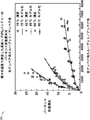
バッテリーの寿命の終わり(EOL)は、典型的に、約20%の容量損失または約30%の内部抵抗に達した時として定義される。EVバッテリーの容量は、バッテリーの内部抵抗が同時間にわたって増大するにつれて、時間とともに減少する。この傾向は、一般に、バッテリーが使用されているか、または使用せずに保管されているかとは無関係である。対応するバッテリー寿命は、概して、カレンダー寿命に関連するため、この状態は、「カレンダーフェード(calendars fade)」と一般的に呼ばれる。図1は、リチウム-マンガン(Li-Mn)バッテリーの60%充電状態(SOC)でのカレンダー寿命対温度についての曲線を有する典型的なグラフ100を示す。Li-Mnバッテリーは、22℃で8年を少し超える寿命(例えば、平均で)を有するが、32℃では5年の寿命しか有さない。時間にわたる平均SOCが60% SOCよりも大きい場合、カレンダー寿命は、図1に示されているものよりも短い。他のタイプのLiイオンバッテリーについて、バッテリー寿命対温度に同様の傾向がある。SOCは、ガソリンで動く自動車における燃料計のように、最大量(100パーセント)に対してどれほどの「燃料」が利用可能であるかを示すことに、注目されたい。従って、60% SOCは、最大の全バッテリー充電の60%が利用可能であることを示す。
The end of life (EOL) of a battery is typically defined as reaching about 20% capacity loss or about 30% internal resistance. The capacity of an EV battery decreases with time as the battery's internal resistance increases over the same time. This trend is generally independent of whether the battery is used or stored without use. Since the corresponding battery life is generally related to the calendar life, this condition is commonly referred to as “calendars fade”. FIG. 1 shows an
バッテリーはまた、使用頻度とともに劣化し、これは「サイクルフェード」として公知である。対応する寿命は、バッテリーサイクル寿命である。図2は、3種の異なる温度:15℃、45℃、および60℃で、実験データに対して黒鉛-LiFePO4バッテリーのサイクル寿命の予測を比較する、グラフ200を示す。グラフ200は、温度の増大とともに、バッテリー容量損失が増大する(またはサイクル寿命が減少する)ことを示す。
Batteries also degrade with frequency of use, known as “cycle fade”. The corresponding lifetime is the battery cycle lifetime. FIG. 2 shows a
図3は、パックレベルで従来の液体冷却を有する、セルモジュールおよびパックを含む先行技術のバッテリー冷却システム300を例証する。セル302A、302B、302C、および302Dは、モジュールにおいて横向きに置かれ、アルミニウム伝導チャネル304A、304B、304C、304D、および304Eによって分離されている。アルミニウム伝導チャネル304A〜Eは、セルの側面からの排熱を補助する。セル302A〜Dとパックジャケット306との間の間隙は、セル302A〜Dの側面から、バッテリー300を冷却または加熱する冷却剤のための通路308を形成している。矢印は、通路308に出入りする冷却剤の流れを示す。エチレングリコール/水(EG/W)溶液が、一般的に、バッテリーパック300のための冷却剤として用いられる。このタイプの設計について、セル302A〜Dは、密閉されたモジュールの中に封入され、流れを遮断し、かつ冷却剤がモジュール端子またはその相互連結部に接触するのを阻止するために、異なるモジュール間にポリマー密閉剤が用いられる。さもなければ、EG/W溶液の漏出が、セル302A〜Dをショートさせ得、場合によっては危険を引き起こし得る。
FIG. 3 illustrates a prior art
図3に示されているものなどの従来のBTMには、本明細書中で議論されるBTM設計において考慮されている、以下の少なくとも四つの問題がある:1)パックレベルで設計されているBTMSは、不均一な温度分布をもたらし得る(約10℃またはそれより大きい温度分布が、パックの単一のセル内で経験され得る);2)バッテリーパックにおける局部的な劣化;3)モジュールおよびパックジャケットの密閉設計が、高い材料または製造費用をもたらす;ならびに4)従来の液体導管設計は、BTMSの重量の増大および小型ではない容積をもたらす。 Conventional BTMs such as those shown in Figure 3 have at least four issues that are considered in the BTM design discussed herein: 1) Designed at the pack level BTMS can result in a non-uniform temperature distribution (a temperature distribution of about 10 ° C. or greater can be experienced within a single cell of the pack); 2) Local degradation in the battery pack; 3) Module and The sealed design of the pack jacket results in high material or manufacturing costs; and 4) conventional liquid conduit designs result in increased BTMS weight and non-compact volume.
議論される不利な点の一つまたは複数を克服するために、ミニチャネル管(例えば、マイクロチャネル管)を含むバッテリーが、提案される。図4は、一つまたは複数の態様に従う、様々なミニチャネル管構造400の例を示す。ミニチャネル管402A、402B、402C、402D、402E、402F、402G、402H、402I、および402Jは、例えば、数十マイクロメートル〜数十ミリメートルの範囲のポート幅または内側水力直径を有する、シングルポート管またはマルチポート管である。多くのミニチャネルは、0.2ミリメートル〜約3ミリメートルの水力直径を含む。ミニチャネル管402A〜Jは、様々なポート形状およびサイズを含み得る。ミニチャネル管402A〜Jは、概ね、長方形、楕円形、または、概ね正方形もしくは丸みのある角もしくは側面を含み得る、他の形状のポートを含むことができる。ポートは、乱流を低減させるか、または層流を助長するのに役立ち得る、突出部を含むことができる。ミニチャネル管に関するさらなる詳細は、図5に関しておよび本明細書における他の場所で議論される。
To overcome one or more of the disadvantages discussed, a battery including a minichannel tube (eg, a microchannel tube) is proposed. FIG. 4 shows examples of various
図5は、一つまたは複数の態様に従う、ミニチャネル管500の例の端面図を示す。ミニチャネル管500は、一つまたは複数のポート504A、504B、504C、504D、504E、504F、504G、504H、504I、504J、504K、または504Lを含むことができる。ポート504A〜Lは、ポート504A〜Lの内部に延びる突出部506A、506B、506C、または506Dを含むことができる。図5は、ポート504A〜Cにおいて最大でも2個の突出部506B〜Cを示し、その突出部506A〜Dを概して直線として示すが、当業者は、本明細書において提供される詳細な説明を読んで理解する際に、異なるサイズ、形状、および数の突出部をポート504A〜Lにおいて使用できることを認識するであろう。突出部506A〜Dの数および形状は、関連するポート504A〜Lにおいて、流れが、より乱流の少ない流体(例えば、液体または気体)を含むのに役立つように構成させることができる。
FIG. 5 shows an end view of an
ミニチャネル管500は、熱伝導率の性能に関係し得る、および、ミニチャネル管500が耐え得る最大圧力を決定することに関係し得る寸法を含むことができる。寸法は、全体の幅502(W)、ポート間の間隔508(WW)、側壁512の厚さ510(Wt)、ポート504A〜Kの幅514(Wc)、およびポート504A〜Kの高さ516(Hc)を含むことができる。一つまたは複数の態様において、幅514は、約数十マイクロメートル〜約数十ミリメートルであり得る。一つまたは複数の態様において、幅614は、約0.2ミリメートル〜約3ミリメートルであり得る。側壁の厚さ512は、熱伝導率の低減を犠牲にしてより高い圧力に耐えることができるより厚い側壁を含めて、様々な厚さであることができる。一つまたは複数の態様において、側壁512の厚さは、約100マイクロメートル〜約200マイクロメートルであることができる。
The
ポート504A〜K内の流体圧または熱伝導率の要求などの要因に応じて、側壁の厚さ510またはポート間隔508を決定することができる。より薄い側壁の厚さ510は、熱伝達(例えば、熱伝導率)を改善することができる。より厚い側壁の厚さ510またはポート間隔508は、ミニチャネル管500がより高い流体圧に耐えるのに役立つことができる。ミニチャネル管500は、概して、高い熱効率(高い熱伝導率)、低い材料費用および重量、ならびに小型設計を有する。ミニチャネル設計における別の考慮は、ポート504A〜Kにおける圧力を低下させる、ポート幅514の増大を含むことができる。
Depending on factors such as fluid pressure in
図6Aは、熱伝達係数(h)対ポート幅514のグラフ600Aを示す。グラフ600Aに示されるように、ポート504A〜Kの熱伝達係数(熱伝導率)は、ポート幅514が増大するにつれて減少する。図6Bは、圧力降下(ΔP)対ポート幅514のグラフ600Bを示す。グラフ600Bに示されるように、圧力降下は、ポート幅514が減少するにつれて減少する。
FIG. 6A shows a
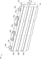
図7および図8は、一つまたは複数の態様に従う、それぞれBTMシステム700および800の一部の例を示す。種々の態様において、ミニチャネル管708A、708B、および708Cを、パックレベル(例えば、図3に示されるような冷却システム)と比較して、(とりわけ、図7および図8に示されるような)セルレベルでの冷却/加熱を伴うBTMSにおいて用いることができる。BTMシステム700は、バッテリー連結器704Aおよび704Bを通して直列に結合した一つまたは複数のバッテリーセル702A、702B、または702Cを含むことができる。システム700は、それらを通してシステム700の電気エネルギーにアクセスする、端子706Aまたは706Bを含むことができる。
7 and 8 show examples of portions of
一つまたは複数のミニチャネル管708A、708B、または708Cは、セル702A〜Cの一つまたは複数に熱的に結合させることができる。ミニチャネル管708A〜Cは、ポリマー、プラスチック、炭素、アルミニウムもしくは他の金属、またはそれらの組み合わせを含む様々な材料を用いて形成することができる。一つまたは複数の態様において、ミニチャネル管708A〜Cを、セル702A〜Cの周りにぴったり適合するように形成することができる。一つまたは複数の態様において、ミニチャネル管708A〜Cを、セル702A〜Cに、はんだ付けする、溶接する、接着剤で付ける、または別の方法で取り付けることができる。ミニチャネル管708A〜Cは、一つまたは複数の態様において、平板アルミニウムマルチポートミニチャネル管(FAMMT)を含むことができる。図7のミニチャネル管708A〜Cは、概ね「U」字形であり(図7の上方視点から見た場合)、かつ、セル702A〜Cの少なくとも二つの側面と接触(例えば、熱的に結合)している。
One or
放熱グリスまたは焼結金属が、ミニチャネル管708A〜Cの一部と対応するセル702A〜Cとの間に間隙がある場所などで、ミニチャネル管708A〜Cとセル702A〜Cとの間の熱的連結を増大させるのに役立つことができる。
The heat dissipating grease or sintered metal is between the
ミニチャネル管708A〜Cの各々を、入力ポート710および出力ポート712に結合させることができる。入力ポート710を、ポート710およびミニチャネル管708A〜Cを通して流体を押し進めることができる、ポンプ(図7および図8には示されていない、図12および図13を参照されたい)に結合させることができる。出力ポート712は、ミニチャネル管708A〜Cから流体を運び去るのに役立つことができる。
Each of the
BTMSにおいて一つまたは複数のミニチャネル管708A〜Cを用いるいくつかの利点は、(a)ミニチャネルを用いて熱効率を増強すること;(b)セルレベルでのより効率的な冷却を通してバッテリーパックにおける不均一な温度分布を低減させること;(c)高価な設計の密閉制約、ならびに、例えば、図3に示されるようなシステムを用いる際に必要とされ得る、セルモジュールおよびパックジャケットの製造を無くすこと;(d)図3に示されるような先行技術のアルミニウム伝導チャネルを無くすこと;(e)バッテリーパックおよびBTMSの全体の設計を単純化すること;(f)全体のパック重量および容積を低減させること;ならびに(g)バッテリーおよび/またはBTMSの製造費用を低減させること、を含むことができる。
Some advantages of using one or
前述の利点に加えて、ミニチャネル管を含むBTMSの冷却剤流体を、ミニチャネル流体システム(例えば、入力ポート710、入力管814(図8を参照されたい)、ミニチャネル管708A〜C、出力ポート712-C、および出力管816(図8を参照されたい)の一つまたは複数の組み合わせ)の中に封入することができ、これは、単に、冷却剤がセル端子およびその相互連結部に接触するリスクを低減させるだけではなく、セル連結設計を単純化する。しかしながら、たとえ漏出の問題が考慮されているとしても、非導電性流体を、ミニチャネル管708A〜Cにおいて用いることができる。例えば、鉱油、変圧器油、種々の冷媒などのある特定の熱伝導性流体などを、使用することができる。さらに、流体金属などの他の熱伝導性媒体を、同様にミニチャネル管708A〜Cにおいて流体として用いることができる。一つまたは複数の態様において、熱伝導性ガスを、ミニチャネル管内の冷却剤として使用してもよい。
In addition to the aforementioned advantages, the BTMS coolant fluid containing the mini-channel tube can be connected to a mini-channel fluid system (eg,
加えて、他のタイプのミニチャネル管を、同様に使用することができる。例えば、良好な(例えば、アルミニウムの熱伝導率とほぼ同じまたはそれより良好な)熱伝導率を有する他の物質を用いて、ミニチャネル管を製造することができる。そのような物質は、例えば、銅、青銅、ならびに他の非鉄物質および鉄物質、炭素含浸ポリマー、または他の熱伝導性プラスチックなどを含むことができる。しかしながら、理解を容易にかつ簡潔にするために、本明細書において使用されるまさにその物質または外形が、市販されているミニチャネル管において見出されるものと同じであるか、または異なり得ることを理解した上で、ミニチャネル管を、本明細書において使用することとする。 In addition, other types of minichannel tubes can be used as well. For example, minichannel tubes can be made using other materials having good thermal conductivity (eg, about the same as or better than that of aluminum). Such materials can include, for example, copper, bronze, and other non-ferrous and ferrous materials, carbon-impregnated polymers, or other thermally conductive plastics. However, for ease and simplicity of understanding, it is understood that the exact materials or profiles used herein may be the same as or different from those found in commercially available minichannel tubes. Thus, a minichannel tube will be used herein.
図7に示されるように、ミニチャネル管708A〜Cを、セル702A〜Cに沿った一つまたは複数の多数の位置で、セル702A〜Cと熱的に非常に近接して配置することができる。種々の態様において、ミニチャネル管708A〜Cを、ミニチャネル管708A〜Cの形状に機械的に厳密に一致するように形成することができる。他の態様において、ミニチャネル管708A〜Cを、例えば、有害な圧力降下を阻止するのを助けるため、またはミニチャネル管内の流体の層流領域を維持するのを助けるために、セル702A〜Cのある特定の外形に関して増大した半径を有するように形成することができる。
As shown in FIG. 7,
加えて、種々の態様において、ミニチャネル管708A〜Cをセル702A〜Cに結合させたものの熱伝導性は、ミニチャネル管708A〜Cとセル702A〜Cとの間のろう付け、溶接、はんだ付け、またはいくつかの他の取り付け機構の使用を通して改善することができる。種々の態様において、ミニチャネル管708A〜Cとセル702A〜Cとの間の熱界面は、種々のタイプの熱伝導性接着剤、グリス、金属焼結、エポキシ樹脂、またはそれらの組み合わせの使用を通して改善することができる。
In addition, in various embodiments, the thermal conductivity of the
概して、セル702A〜Cの内側で発生した熱は、伝導を通してミニチャネル管708A〜Cに輸送され、その後、流体対流を通して放散される。熱放散速度は、流体の流速に直接依存し、これは、制御シグナルとしてのセル702A〜Cの検知された温度で、閉ループ制御システムによって制御することができる。閉ループ制御システムは、当技術分野において独立して公知である閉ループ制御の概念に基づいて、当業者により理解される。
In general, the heat generated inside the
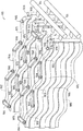
図8は、複数の列のセル802A A〜Fが合わせて(直列に)結合されてパックにされている、システム700に類似したシステム800を示し、他方、図7は、パックを形成するように合わせて結合された、単一の列のセル702A〜Cを示す。セル802A、802B、802C、802D、802E、802F、802I、802J、802K、802L、802M、802N、および802Oは、セル702A〜Cと実質的に同じであることができ、連結器704A〜Bと実質的に類似していることができるバッテリー連結器804A、804B、804C、804D、804E、804F、804G、804H、804I、804J、804K、804L、804M、または804Nを通して直列に結合させることができる。システム800は、それらを通してシステム800A〜Bの電気エネルギーにアクセスする、端子706A〜Bに類似した端子806Aおよび806Bを含むことができる。図8に示されるように、入力ポート810A、810B、および810Cは、共通の入力管814に結合することができ、出力ポート812A、812B、および812Cは、共通の出力管816に結合することができる。本明細書において用いられる際、「実質的に同じ」とは、アイテムを、実質的に同じであるアイテムと同じまたは類似した物質で作製できることを意味する。システム800のミニチャネル管808A〜Cは、隣接した列のセルと接触することができる(例えば、セル802A〜Cおよび802D〜Fは、独立した列のセルであり、互いに隣接していることができる)。ミニチャネル管808A〜Cは、セル802A〜Cの列およびセル802D〜Fの列と、同時に熱的に結合する(例えば、熱的に接触する)ように構成させることができる。
FIG. 8 shows a
図9および図10は、一つまたは複数の態様に従う、それぞれBTMシステム900および1000の一部の例を示す。セル902A、902B、902C、902D、902E、902F、902G、902H、902J、902K、および902L、ならびにセル1002A、1002B、1002C、1002D、1002E、1002F、1002G、1002H、1002J、1002K、および1002Lは、セル702A〜Cと実質的に同じであることができ、セル902A〜Lおよび1002A〜Lは、不規則な形状を含む。ミニチャネル管908A、908B、908C、ならびに1008A、1008B、および1008Cは、ミニチャネル管708A〜Cと実質的に同じであることができ、ミニチャネル管908A〜Cおよび1008A〜Cは、それぞれセル902A〜Lおよび1002A〜Lの輪郭に従う形状を含む。これらの図は、ミニチャネル管708A〜C、808A〜C、908A〜C、および1008A〜Cを、非標準セル上で用いることができ、かつ多種多様のセル形状に適合できることを実証するように意図されている。いくつかのミニチャネル管形状は、使用時に効率が低いか、または非実用的でさえあるような、圧力降下または管内の乱流などの問題点を創出し得る。
9 and 10 show examples of portions of
連結器904A、904B、904C、904D、904E、904F、904G、904H、904I、904J、および904K、ならびに1004A、1004B、1004C、1004D、1004E、1004F、1004G、1004H、1004I、1004J、および1004Kは、連結器704A〜Bと実質的に同じであることができ;端子906Aおよび906B、ならびに1006Aおよび1006Bは、端子706A〜Bと実質的に同じであることができ;入力ポート910A、910B、910C、および910D、ならびに1010A、1010B、1010C、および1010Dは、入力ポート710と実質的に同じであることができ;出力ポート912A、912B、912C、および912D、ならびに1012A、1012B、1012C、および1012Dは、出力ポート712と実質的に同じであることができ;入力管914および1014は、入力管814と実質的に同じであることができ;ならびに、出力管916および1016は、出力管816と実質的に同じであることができる。ポート910A〜D、912A〜D、1010A〜D、および1012A〜D、ならびに管914、916、1014、および1016は、ミニチャネル管708A〜Cと同じ物質を含むことができ、かつまた、他の物質を含むこともできる。ポート710、712、810A〜C、812A〜C、910A〜D、912A〜D、1010A〜D、および1012A〜D、または管914、916、1014、および1016は、例えば、その中の流体の温度を一定のままにするのに役立つように、断熱することができる。
図11Aは、一つまたは複数の態様に従う、バッテリー1100Aの例を示す。バッテリー1100Aは、一つまたは複数のくぼみ1104A、1104B、1104C、1104D、1104E、または1104Fを含むセル1102A、ならびに一つまたは複数の端子1106Aおよび1106Bを含むことができる。ミニチャネル管708A〜C、808A〜C、908A〜C、または1008A〜Cを、くぼみ1104A〜F中に少なくとも部分的に差し入れることができる。管708A〜C、808A〜C、908A〜C、または1008A〜Cを、くぼみ1104A〜Fに差し入れることによって、管808A〜C、908A〜C、または1008A〜Cは、セル1102Aに接触する、より大きな表面積を有することができ、従って、より効率的な加熱または冷却を提供することができる。図11Aは、くぼみ1104A〜Fを長方形の形状を含むものとして示すが、くぼみ1104A〜Fは、とりわけ、楕円、丸みのある角の形状、多角形、不規則な形状、またはそれらの組み合わせなどの別の形状を含むことができる。
FIG. 11A shows an example of a
図11Bは、一つまたは複数の態様に従う、バッテリー1100Bの例を示す。バッテリー1100Bは、セル1102Bの内部の一つまたは複数のミニチャネル管1108A、1108B、1108C、または1108Dを含むセル1102B、ならびに、一つまたは複数の端子1106Aおよび1106Bを含むことができる。ミニチャネル管1108A〜Dは、セル1102Bの電解質と接触していることができる(図を不明瞭にすることを回避するために、電解質は示されていない)。ミニチャネル管1108A〜Dは、ミニチャネル管708A〜C、808A〜C、908A〜C、または1008A〜Cと実質的に同じであることができる。セル1102Bの内部に管1108A〜Dを作製することによって、管1108A〜Dは、セル1102Bに接触する、より大きな表面積を有することができ、従って、より効率的な加熱または冷却を提供することができる。また、管1108A〜Dは、例えば、セル1102A〜Dの内部に構成可能な熱プロファイルを提供するために、セル1102Bの内部の任意の場所に位置することができる。例えば、セル1102Bを特定の温度範囲内により効率的に保つのに役立つために、管1108A〜Dを、セル1102Bの典型的により温かいまたはより冷たい地点により近いように位置づけることができる。セル1102Bの内部の管1108A〜Dを用いる際には、管の材料がバッテリー1100Bの化学的性質と適合性であることを確認するように、気をつけるべきである。例えば、Liイオンバッテリーの化学的性質は、アルミニウム管を実質的に腐食しないかまたは損傷を与えないため、アルミニウム管を、Liイオンバッテリーの内部に用いることができる。
FIG. 11B shows an example of a
図12は、一つまたは複数の態様に従う、BTMS 1200の例を示す。BTMS 1200は、一つまたは複数のセル1202Aおよび1202B、一つまたは複数の連結器1204A、ならびに一つまたは複数の端子1206Aおよび1206Bを含む、バッテリーを含むことができる。セル1202A〜Bは、一つまたは複数のミニチャネル管1208A、1208B、または1208Cに熱的に結合させることができる。管1208A〜Cは、入力ポート1210および出力ポート1212を通してポンプ1214に結合させることができる。ポンプ1214は、管1208A〜Cにおいて流体を移動させることができる。ポンプ1214は、とりわけ、往復ポンプ、回転ポンプ、またはせん断力ポンプであることができる。システム1200は、例えば、ミニチャネル管の各々において流体の流速を個々に変動させる能力を提供するために、複数のポンプを含むことができる。セル1202A〜Bは、セル702A〜C、808A〜F、902A〜L、またはセル1002A〜Lと実質的に同じであることができる。ミニチャネル管1208A〜Cは、管708A〜C、808A〜C、908A〜C、または1008A〜Cと実質的に同じであることができる。入力ポート1210は、入力ポート710、810A〜C、910A〜D、または1010A〜Dと実質的に同じであることができる。出力ポート1212は、出力ポート712、812A〜C、912A〜D、または1012A〜Dと実質的に同じであることができる。連結器1204Aは、連結器704A〜B、804A〜G、904A〜K、または1004A〜Kと実質的に同じであることができる。端子1206A〜Bは、端子706A〜B、806A〜B、906A〜B、または1006A〜Bと実質的に同じであることができる。
FIG. 12 shows an example of a
流体を、ポンプ1214から加熱器/冷却器1216にポンプで注入することができる。加熱器/冷却器1216は、(図12には示されていない温度センサーを用いて)流体の温度を検知し、流体を特定の温度範囲内に加熱/冷却するか、または、プロセッサ1228からの制御シグナルに基づいて流体を加熱/冷却することができる。流量調節器1218は、加熱器/冷却器1216からの流体の流速を増大または減少させることができる。流量調節器1218は、管1208A〜Cにおける流体の流れを層状に保つのに役立つことができる。流量調節器1218を、流量計1220に通信可能に結合させることができる。流量計1220は、流体の流れを特定の範囲内に保つのに役立つように用いることができるプロセッサ1228に、データを提供することができる。フィルター1222は、流体における目詰まりまたは乱流を阻止するのに役立つように、流体から粒子を除去することができる(例えば、システム1200の内壁から脱粒して生じた粒子、または流体内に入ったかもしくは含有された粒子)。圧力変換器1224を、ポンプ1214および流量調節器1218に通信可能に結合させることができる。圧力変換器は、ポート1210および1212、または管1208A〜Cにおける流体の圧力を決定することができる。圧力変換器1224は、例えば、流体の流れを特定の範囲内に保つのに役立つために、ポンプ1214または流量調節器1218を制御するのに役立つように用いることができるプロセッサ1228に、データを提供することができる。
Fluid can be pumped from the
フィルター1222の孔サイズは、数多くの要因に基づいて決定することができる(例えば、ミニチャネル管1208A〜B内の濾過されるべき粒子サイズから決定する)。フィルター内のより小さな孔サイズは、BTMS内の粒子の数を低減させることができるが、より小さな孔サイズはまた、圧力降下を増大させ得、その結果として、システムを通して流体を再循環させるために必要とされる力を増大させ得る。従って、性能指数(例えば、圧力降下の関数としての濾過効率)を、所定のシステムのために所定のBTMSを設計する上で考慮することができる。また、より大きな表面積を有するフィルターと並行して、または代替的に、または追加的に配置される複数のフィルターを、考慮することができる。
The pore size of the
負荷1226は、EVまたは本明細書において議論される他のアイテムなどの、セル1202A〜Bの電力を流すことができる任意のアイテムであることができる。プロセッサ1228は、ハードウェア、ソフトウェア、ファームウェア、またはそれらの組み合わせを含むことができる。プロセッサ1228は、例えば、ポンプが作動する速度を制御するために、ポンプ1214にシグナルを提供することができる。プロセッサ1228は、例えば、加熱器/冷却器1216の温度設定を制御するために、加熱器/冷却器1216にシグナルを提供することができる。プロセッサ1228は、例えば、流量調節器1218が流体の流れを遅くする割合を制御するために、流量調節器1218にシグナルを提供することができる。プロセッサ1228は、圧力変換器1224、流量計1220、または温度センサー(図12には示されていない、図13を参照されたい)から、管1208A〜Cにおける流体の流速、流体の温度、または圧力を調節するのに役立つようにプロセッサ1228によって用いられ得る、データを受け取ることができる。ポンプ1214、プロセッサ1228、加熱器/冷却器1216、流量調節器1218、または流量計1220は、セル1202A〜Bまたは別の電源で動く。
The
図13は、一つまたは複数の態様に従う、BTMS 1300の例を示す。BTMS 1300は、一つまたは複数のセル1302Aおよび1302B、一つまたは複数の連結器1304A、ならびに一つまたは複数の端子1306Aおよび1306Bを含む、バッテリーを含むことができる。セル1302A〜Bは、一つまたは複数のミニチャネル管1308A、1308B、または1308Cに熱的に結合させることができる。管1308A〜Cは、入力ポート1310および出力ポート1312を通してポンプ1314に結合させることができる。ポンプ1214は、管1308A〜Cにおいて流体を動かすことができる。ポンプ1314は、とりわけ、往復ポンプ、回転ポンプ、またはせん断力ポンプであることができる。
FIG. 13 shows an example of a
ポンプ1314は、弁1318に流体を提供することができる。弁1318は、流体が冷却されるべき場合は冷却器1316に、熱を流体から放散させるべき場合は放熱器1324に、または、流体が加熱されるべき場合は加熱器1320に、流体を方向づけることができる。温度センサー1326は、セル1302A〜Bの温度を測定するのに役立つことができる。温度センサー1326、ポンプ1314、弁1318、冷却器1316、および加熱器1320は、各々、プロセッサ(図13には示されていない、図12を参照されたい)に電気的にまたは通信可能に結合させることができる。プロセッサは、ポンプの速度(例えば、容積流速または質量流速)を制御することができる。プロセッサは、例えば、弁1318の外への流体の流れの方向を制御するために(例えば、弁出力を開いてまたは閉じて、加熱器1320、放熱器1324、または冷却器1316に流体を方向づけるために)、弁1318を制御することができる。冷却器1316がどれほど流体を冷却するかを制御するために、プロセッサを冷却器1316に結合させることができる。加熱器1320がどれほど流体を加熱するかを制御するために、プロセッサを加熱器1320に結合させることができる。温度センサー1326は、プロセッサが加熱器1320および冷却器1316を制御し、流体を特定の温度範囲に保つのに役立つように、データを提供することができる。
The
セル1302A〜Bは、セル702A〜C、808A〜F、902A〜L、またはセル1002A〜Lと実質的に同じであることができる。ミニチャネル管1308A〜Cは、管708A〜C、808A〜C、908A〜C、または1008A〜Cと実質的に同じであることができる。入力ポート1310は、入力ポート710、810A〜C、910A〜D、または1010A〜Dと実質的に同じであることができる。出力ポート1312は、出力ポート712、812A〜C、912A〜D、または1012A〜Dと実質的に同じであることができる。連結器1304Aは、連結器704A〜B、804A〜G、904A〜K、または1004A〜Kと実質的に同じであることができる。端子1306A〜Bは、端子706A〜B、806A〜B、906A〜B、または1006A〜Bと実質的に同じであることができる。
Cells 1302A-B can be substantially the same as
図12および図13のアイテムは、相互排除的ではないことに、注目されたい。図12に示されていないが図13に示されているアイテムを、図12のシステムにおいて用いることができ、逆もまた同様である。また、図12および図13のアイテムのすべてが、稼働可能なBTMSを作製するために必要とされるわけではない。アイテムのうちのいくつかは、BTMSの制約に応じて任意であることができる。例えば、BTMSのアイテムが非常に厳密な圧力制約を有さない場合は、圧力変換器をBTMSから省くことができる。 Note that the items in FIGS. 12 and 13 are not mutually exclusive. Items not shown in FIG. 12 but shown in FIG. 13 can be used in the system of FIG. 12 and vice versa. Also, not all of the items in FIGS. 12 and 13 are required to create an operational BTMS. Some of the items can be optional depending on BTMS constraints. For example, if the BTMS item does not have very strict pressure constraints, the pressure transducer can be omitted from the BTMS.
流体の流体流速は、動的な作業条件下でセル1302A〜Bの測定される温度をあらかじめ設定されたレベルに保つために、動的であることができる。加えて、セルの内側で生じ得る不均質な熱発生のために、ミニチャネル管の外形、管構成、および流速を、各セルにおける不均一な温度分布を低減または最小化させるように調整することができる。さらに、ミニチャネル技術は、セルの外側からセルを冷却できるだけではなく、セルの内側に埋め込んで(図11Bに示されるように)セルの内側からのより効率的な冷却を達成することができる。 The fluid flow rate of the fluid can be dynamic to keep the measured temperature of the cells 1302A-B at a preset level under dynamic working conditions. In addition, due to inhomogeneous heat generation that can occur inside the cell, the mini-channel tube profile, tube configuration, and flow rate are adjusted to reduce or minimize the non-uniform temperature distribution in each cell. Can do. In addition, mini-channel technology can not only cool the cell from the outside of the cell, but also can be embedded inside the cell (as shown in FIG. 11B) to achieve more efficient cooling from the inside of the cell.
温度センサー1326などによる、セルの温度検知は、例えば、熱電対、抵抗温度検出器、または当技術分野において公知である他の温度検知装置を使用することによって、成し遂げることができる。ミニチャネル管中の流体を、セルの近くを通過している間に加熱または冷却することができ、流体によって運ばれる熱を、送風機または加熱/冷却ループに連結された放熱器(例えば、熱交換器)に放出することができ、熱の一部を、BTMSのアイテムの間で流体を運ぶチャネルを通して放散させることができる。
Cell temperature sensing, such as by
ミニチャネル管内の流体を再循環させるために、ポンプを用いることができる。種々のタイプのポンプを、使用することができる。ポンプは、セルより上流および/または下流のいずれかであることができる。また、追加的なポンプを、必要とされ得る種々の流速に応じて、一つまたは複数のミニチャネル管のうちの種々のものに対して用いることができる。任意で、BTMS内のミニチャネル管の所定の一つについて種々の流速を提供するために、流量調節弁を、ミニチャネル管の一つまたは複数の上に置くことができる。種々の態様において、BTMS内の種々のミニチャネル管の間での種々の相対流速の決定値を、(例えば、所定のEVのための所定のバッテリーについて)あらかじめ知ることができる。この場合、種々のミニチャネル管の間に相対的な流量の差を提供するために、(例えば、所定の上流/下流の圧力のための所定の流速に関連する)種々のサイズのクリティカルオリフィスを、ミニチャネル管のうちの選択されたものにおいて用いることができる。 A pump can be used to recirculate the fluid in the minichannel tube. Various types of pumps can be used. The pump can be either upstream and / or downstream from the cell. Additional pumps can also be used for various ones or one or more minichannel tubes, depending on the various flow rates that may be required. Optionally, a flow control valve can be placed on one or more of the minichannel tubes to provide various flow rates for a given one of the minichannel tubes in the BTMS. In various embodiments, various relative flow rate decisions between various minichannel tubes in the BTMS can be known in advance (eg, for a given battery for a given EV). In this case, various sizes of critical orifices (eg, associated with a given flow rate for a given upstream / downstream pressure) may be used to provide a relative flow difference between the various minichannel tubes. Can be used in selected ones of the mini-channel tubes.
EV内での使用の場合、EVのバッテリーを用いて、ミニチャネル管内の流体を再循環させるためのポンプを駆動することができる。他の態様において、電荷貯蔵システムを有する光電池、コンセント電力、または別個のバッテリーなどの別個の電源を用いて、ポンプを動かすことができる。また、BTMSを、セルからよりもむしろ、セルへ熱伝達を提供するように適応させることができる。そのような「逆」熱伝達システム(例えば、セルの加熱)は、寒い気候において有用であり得る。従って、BTMSを、セルへおよびセルからの両方の熱伝達を組み入れるように設計することができる。例えば、BTMSは、セルと機械的にまたは物理的に接触していないミニチャネル管の一部のみにまたは外側表面全体上に、抵抗加熱器を熱的に結合させることによって、電気抵抗加熱を用いることができる。種々の態様において、ミニチャネル管内の流体を、フィルターまたはポンプの位置で、例えば、その近くで、遠隔的に加熱することができる。種々の態様において、遠隔加熱およびセルの近位での抵抗加熱の両方を、上記で議論されている冷却過程と同じまたは類似した過程において使用することができる。 For use within an EV, the EV battery can be used to drive a pump for recirculating fluid in the minichannel tube. In other embodiments, the pump can be operated using a separate power source, such as a photovoltaic cell with a charge storage system, outlet power, or a separate battery. BTMS can also be adapted to provide heat transfer to the cell rather than from the cell. Such “reverse” heat transfer systems (eg, cell heating) may be useful in cold climates. Thus, BTMS can be designed to incorporate both heat transfer to and from the cell. For example, BTMS uses electrical resistance heating by thermally coupling a resistance heater to only a portion of the minichannel tube that is not in mechanical or physical contact with the cell or over the entire outer surface. be able to. In various embodiments, the fluid in the minichannel tube can be remotely heated at, for example, near the filter or pump. In various embodiments, both remote heating and resistance heating near the cell can be used in the same or similar process as the cooling process discussed above.
図14Aおよび図14Bは、一つまたは複数の態様に従う、それぞれ、それに熱的に結合したミニチャネル管を含む角柱セルのシミュレーション、およびミニチャネル管の近くの熱プロファイルのより限局的な画像の、シミュレートされた熱の図1400Aおよび1400Bの例を示す。数値結果は、以前のBTMSと比較して、ミニチャネル技術を用いたより効率的な冷却を示すことができる。図14Aおよび図14Bを作成するのに用いられた支配方程式およびシミュレーションを説明する助けとなるように、本明細書において解析が提供されている。 14A and 14B show a simulation of a prismatic cell including a minichannel tube thermally coupled thereto, respectively, and a more localized image of the thermal profile near the minichannel tube, according to one or more aspects, Figures 1400A and 1400B show examples of simulated heat. The numerical results can indicate more efficient cooling using mini-channel technology compared to previous BTMS. An analysis is provided herein to help explain the governing equations and simulations used to create FIGS. 14A and 14B.
以下は、BTMSを創作する際のいくつかの設計検討の解析であり、解析を理解する助けとなるように、図のいくつかに参照がなされる。ミニチャネル管における流体の流れは、概して、低いレイノルズ数(Re)のために層流領域にある。層流において、局所熱伝達係数hは、図6Aに示されているように、管の直径と反比例して変動する(すなわち、hα1/D)。直管において完全に発生した層流について、圧力降下(ΔP)を、式1:ΔP=32*μ*V*L/D2(式中、μは流れの粘度であり、Vは流速であり、Lは管の長さであり、およびDはポートの水力直径である)を用いて算出することができる。図6Bは、固定された流速およびポート長での、圧力降下対ポート直径を例証する。いくつかの熱管理システムについて、入口プレナムおよび出口プレナム、ならびにポート湾曲からの影響を、ポンピング力の必要量の概算において考慮することができる。ミニチャネル管の流体の流れは、高い熱伝達係数の利点を有するが、ミニチャネル管は、大きい圧力降下を引き起こし、かつ付随的に高いポンピング力を必要とし得、これにより生じる障害は、圧力降下の方程式に基づき得るように、管の長さまたは流速を低減させることを通して少なくとも部分的に克服することができる。 The following is an analysis of some design considerations when creating a BTMS, and references are made to some of the diagrams to help understand the analysis. The fluid flow in the minichannel tube is generally in the laminar region due to the low Reynolds number (Re). In laminar flow, the local heat transfer coefficient h varies inversely with the tube diameter (ie, hα1 / D), as shown in FIG. 6A. For a laminar flow completely generated in a straight pipe, the pressure drop (ΔP) is expressed by the equation 1: ΔP = 32 * μ * V * L / D 2 (where μ is the flow viscosity and V is the flow velocity) , L is the length of the tube, and D is the hydraulic diameter of the port). FIG. 6B illustrates pressure drop versus port diameter at a fixed flow rate and port length. For some thermal management systems, the effects from the inlet and outlet plenums and port curvature can be considered in estimating the pumping force requirements. Although the fluid flow of the mini-channel tube has the advantage of a high heat transfer coefficient, the mini-channel tube can cause a large pressure drop and concomitantly require a high pumping force, resulting in a pressure drop Can be overcome at least in part through reducing the length or flow rate of the tube, as can be based on the following equation:
図5は、以前に議論されているようなミニチャネル管の寸法を示す。便宜上、寸法を再び提示する。寸法は、全体の幅502(W)、ポート間の間隔508(WW)、側壁512の厚さ510(Wt)、ポート504A〜Kの幅514(Wc)、およびポート504A〜Kの高さ516(Hc)を含むことができる。別のパラメータは、ポートの長さ(L)を含む。これらの設計パラメータの様々な組み合わせが、非線形探索アルゴリズムを用いて成し遂げられ得るように、最適化のための大きな探索空間をもたらすことができる。
FIG. 5 shows the dimensions of the mini-channel tube as previously discussed. For convenience, the dimensions are presented again. Dimensions include overall width 502 (W), spacing between ports 508 (W W ),
圧力降下(ΔP)および温度増大(ΔT最大)についての経験的モデルを、本明細書において説明する。市販のCOMSOL Multiphysics(登録商標)ソフトウェア(COMSOL, Inc., Burlington, Massachusetts, U.S.A.から入手可能)を用いた共同数値シミュレーションおよび実験を行って、経験的モデル、およびミニチャネル管をBTMSに応用する実現可能性を探査した。50/50 EG/W溶液を、流体として用いた。ガイドラインとして数値結果を用いて、基本型の実験室規模の冷却システムを製作し、2種の経験的モデルを検証および較正するために試験した。米国エネルギー省(DOE)アルゴンヌ国立研究所によって開発されたBatPaC費用モデルを用いて、新たなBTMSの費用解析を説明し、流体冷却を伴う従来のBTMSのものと比較する。BTMSのためのミニチャネル冷却の実現可能性は、研究に基づいて確認された。 An empirical model for pressure drop (ΔP) and temperature increase (ΔT max ) is described herein. Collaborative numerical simulations and experiments using commercially available COMSOL Multiphysics® software (available from COMSOL, Inc., Burlington, Massachusetts, USA) to implement empirical models and minichannel tubes for BTMS Exploring possibilities. A 50/50 EG / W solution was used as the fluid. Using numerical results as a guideline, a basic laboratory-scale cooling system was built and tested to validate and calibrate two empirical models. Using a BatPaC cost model developed by the US Department of Energy (DOE) Argonne National Laboratory, a cost analysis of a new BTMS will be described and compared to that of a conventional BTMS with fluid cooling. The feasibility of mini-channel cooling for BTMS has been confirmed based on research.
バッテリー熱の発生および輸送の数値モデリングおよびシミュレーションは、全体のバッテリー性能、安全性、および寿命を増強する方法を見出す助けとなるように用いることができるツールである。COMSOL Multiphysics(登録商標)ソフトウェアに組み込まれたBatteries & Fuel Cells ModuleおよびHeat Transfer Moduleは、化学反応による熱発生過程、ならびに、拡散、対流、および放射を含む熱輸送過程をシミュレートするために適用されたツールのセットを提供した。 Numerical modeling and simulation of battery heat generation and transport is a tool that can be used to help find ways to enhance overall battery performance, safety, and lifetime. The Batteries & Fuel Cells Module and Heat Transfer Module embedded in COMSOL Multiphysics® software are applied to simulate heat generation processes due to chemical reactions and heat transport processes including diffusion, convection and radiation. Provided a set of tools.
概して、2種の一般的なタイプのLiイオンセル:より小さな電荷容量(例えば、5Ah未満)を有する円柱セル、およびより大きな電荷容量(例えば、10 Ahより大きい)を有する角柱セルが存在する。いくつかの予備的な結果を得るために、熱の発生および輸送を、COMSOLを用いて円柱セルにおいて研究した。しかしながら、角柱セルのより大きな電荷容量によって、角柱セルは、例えば、より大きな運転範囲(例えば、およそ250マイル〜約300マイル)を達成するのに役立つために、大きなバッテリーパックを有するEVなどに対して、より広く応用可能となる。 In general, there are two common types of Li ion cells: cylindrical cells with smaller charge capacities (eg, less than 5 Ah) and prismatic cells with larger charge capacities (eg, greater than 10 Ah). To obtain some preliminary results, heat generation and transport were studied in cylindrical cells using COMSOL. However, due to the larger charge capacity of prismatic cells, prismatic cells, for example, for EVs with large battery packs, etc. to help achieve a larger operating range (eg, approximately 250 miles to approximately 300 miles) And more widely applicable.
直列接続した2個の角柱セルのための実験室規模のミニチャネル冷却システムを、ΔT最大およびΔPを見出すために研究した。全体の熱抵抗(R0)は、以下のように方程式2:R0=ΔT最大/Q熱(式中、Q熱は全バッテリー熱生成率である)において定義される。ひとたびR0が与えられるかまたは分かると、異なる加熱条件での最大温度増大(ΔT最大)を、方程式(2)に基づいて概算することができる。全熱抵抗R0は、方程式3:R0=Rセル+Rベース+REG/W+R対流(式中、RセルおよびRベースは、それぞれ、セルおよびミニチャネルベースの伝導熱抵抗に相当し、REG/Wは、EG/W冷却剤のカロリー熱抵抗であり、およびR対流は対流熱抵抗である)に示されるように、4種の構成要素に分けることができる。方程式(3)における最初の3種の構成要素を概算することは簡単明瞭であるが、R対流を見出すために研究努力が費やされ得る。対流熱伝達を特徴決定する一般的かつ便利な方法は、無次元ヌッセルト数(Nu)によるものである。R対流は、ミニチャネル軸に沿った積分によってNuから計算することができる。 A laboratory scale mini-channel cooling system for two prismatic cells connected in series was studied to find ΔT max and ΔP. The overall thermal resistance (R 0 ) is defined in Equation 2: R 0 = ΔT max / Q heat (where Q heat is the total battery heat production rate) as follows: Once R 0 is given or known, the maximum temperature increase (ΔT max ) at different heating conditions can be estimated based on equation (2). Total thermal resistance R 0 is Equation 3: R 0 = R cell + R base + R EG / W + R convection (where R cell and R base correspond to the conduction thermal resistance of cell and minichannel base , respectively, R EG / W can be divided into four components, as shown in EG / W coolant calorie heat resistance and R convection is convective heat resistance. Although it is straightforward to approximate the first three components in equation (3), research efforts can be expended to find R convection . A common and convenient way to characterize convective heat transfer is by the dimensionless Nusselt number (Nu). R convection can be calculated from Nu by integration along the minichannel axis.
ミニチャネル管における圧力降下は、方程式4:ΔP=f*(L/Dh)*(0.5*ρf *V2)(式中、ρfは流体密度であり、およびDhは水力直径である)におけるように、完全に発生した層流について摩擦因子(f)を用いることによって計算することができる。Dhは、方程式5:Dh=(2*α*Wc)/(1+α)(式中、α=Hc/Wcはミニチャネルの縦横比)を用いて決定することができる。 The pressure drop in the minichannel tube is given by Equation 4: ΔP = f * (L / D h ) * (0.5 * ρ f * V 2 ), where ρ f is the fluid density and D h is the hydraulic diameter. As in), for a completely generated laminar flow, it can be calculated by using the friction factor (f). D h can be determined using Equation 5: D h = (2 * α * W c ) / (1 + α), where α = H c / W c is the aspect ratio of the minichannel.
これらの方程式に基づいた熱伝達シミュレーションからの結果を、図14Aおよび図14Bに提示する。シミュレーションは、COMSOL Multiphysics(登録商標)ソフトウェアを用いて完成させた。図14Aおよび図14Bは、3本のミニチャネル管ストライプを通した水冷却を伴う、単一角柱セル上のミニチャネルのシミュレーションを示す。 Results from heat transfer simulations based on these equations are presented in FIGS. 14A and 14B. The simulation was completed using COMSOL Multiphysics® software. 14A and 14B show a simulation of a minichannel on a single prismatic cell with water cooling through three minichannel tube stripes.
対流熱伝達係数(Nu)および摩擦因子fについての経験的モデルを、それぞれ、創出することができる。具体的には、対流熱伝達を、レイノルズ数Re(Re=ρf *V*Dh/μ)、プラントル数Pr(Pr=Cp *μ/k、式中、Cpおよびkは、それぞれ、EG/Wの比熱および熱伝導率である)の関数として、モデル化することができる。 Empirical models for the convective heat transfer coefficient (Nu) and the friction factor f can be created, respectively. Specifically, the convective heat transfer is expressed by Reynolds number Re (Re = ρ f * V * D h / μ), Prandtl number Pr (Pr = C p * μ / k, where Cp and k are respectively Can be modeled as a function of EG / W specific heat and thermal conductivity.
設計ガイドラインとして数値シミュレーションを用いて、BTMSを設計することができる。基本型BTMSは、Wc=1.33 mm、Hc=2.72 mm、Ww=0.25 mm、Wt=0.51 mm、およびW=25.40 mmのミニチャネル管外形を含んだ(対応する寸法については、図5を参照されたい)。ミニチャネル管を、入口ポートおよび出口ポートとして機能する、2本の差し入れられたアルミニウム管と溶接した。冷却ループの概略図を、図12に示す。ギアポンプを用いて、ループの内側に50/50 EG/W溶液を駆動した。流速を、流量調節弁によって制御し、容積流速を、流量計によって測定した。流れフィルターを用いて、ミニチャネル管が目詰まりすることを阻止した。ミニチャネルにわたる圧力降下(ΔP)を、圧力変換器によってモニタリングした。概ね一定の温度を有する水浴(例えば、加熱器/冷却器)を用いて、ミニチャネル管の入口でEG/W溶液を一定の温度に保った。直列接続の2個のバッテリーを、コンピュータで制御されたバッテリーサイクラー(例えば、負荷)に連結させて、プログラムされた変化/放電サイクルを作動させた。多岐管(例えば、入力ポート1210Aおよび出力ポート1212A)における温度を、熱電対で測定した。圧力および温度の測定値についてのデータを、コンピュータソフトウェア(例えば、National Instruments(登録商標), Austin, Texas, U.S.A.から入手可能であるCompactDAQモジュールおよびLABVIEW)を用いて収集した。バッテリーにおける温度変化を、赤外線カメラによって記録した。外部環境の影響を低減させるのに役立つように、バッテリーおよびミニチャネル管冷却装置を、断熱層によって覆った。 BTMS can be designed using numerical simulation as a design guideline. The basic BTMS included a mini-channel tube profile with Wc = 1.33 mm, Hc = 2.72 mm, Ww = 0.25 mm, Wt = 0.51 mm, and W = 25.40 mm (see Figure 5 for corresponding dimensions) Wanna) The minichannel tube was welded with two inserted aluminum tubes that function as inlet and outlet ports. A schematic diagram of the cooling loop is shown in FIG. A 50/50 EG / W solution was driven inside the loop using a gear pump. The flow rate was controlled by a flow control valve and the volume flow rate was measured by a flow meter. A flow filter was used to prevent the minichannel tube from becoming clogged. The pressure drop (ΔP) across the minichannel was monitored by a pressure transducer. A EG / W solution was maintained at a constant temperature at the inlet of the minichannel tube using a water bath (eg, heater / cooler) having a generally constant temperature. Two batteries in series were connected to a computer controlled battery cycler (eg, a load) to activate a programmed change / discharge cycle. The temperature at the manifold (eg, input port 1210A and output port 1212A) was measured with a thermocouple. Data for pressure and temperature measurements were collected using computer software (eg, CompactDAQ module and LABVIEW available from National Instruments®, Austin, Texas, U.S.A.). The temperature change in the battery was recorded with an infrared camera. To help reduce the impact of the external environment, the battery and mini-channel tube cooler were covered by a thermal insulation layer.
前述の説明は、実験室規模のBTMSに関するものであるが、実験室規模の冷却システムからスケールアップすることにより、同じまたは類似した経験的モデルを応用して、任意の他のバッテリーパックのための本格的規模のBTMSを設計することができる。スケールアップしたBTMSにおいては、第2の(またはそれより多い)冷媒ループまたは加熱器を用いて、異なるバッテリー操作条件で流体温度を制御するのを助けることができる。 The foregoing description is for laboratory scale BTMS, but by applying the same or similar empirical model by scaling up from a laboratory scale cooling system, it can be used for any other battery pack. Full-scale BTMS can be designed. In scaled-up BTMS, a second (or more) refrigerant loop or heater can be used to help control fluid temperature at different battery operating conditions.
本明細書において議論される研究によって、本明細書において議論されるBTMSは、従来の冷却システムよりも小型でかつより軽量であり得ることが示された。また、新たな冷却システムの予測される製造費用は、従来の流体冷却システムよりも20%低いかまたはそれを超え得る。 The studies discussed herein have shown that the BTMS discussed herein can be smaller and lighter than conventional cooling systems. Also, the expected manufacturing cost of a new cooling system can be 20% lower or more than conventional fluid cooling systems.
図15は、一つまたは複数の態様に従う、方法1500の例の流れ図を示す。示されているような方法1500は、操作1502で、一つまたは複数のミニチャネル管に流体をポンプで注入する工程;操作1504で、バッテリーのセルの温度を測定する工程、および、操作1506で、セルの温度を特定の温度範囲内に維持するように、流体の温度を変化させる工程(例えば、流体を加熱または冷却する工程)を含む。一つまたは複数のミニチャネル管は、バッテリーパックの一つまたは複数のセルに熱的に結合していることができる。セルは、一つまたは複数のセルのうちの一つのセルであることができる。
FIG. 15 shows a flowchart of an
方法1500は、一つまたは複数のミニチャネル管の各々において流体の流速を個々に変動させる工程を含むことができる。1506での操作は、例えば、一つまたは複数のセルの電解質と接触するように、セルの少なくとも部分的に内部にある一つまたは複数のミニチャネル管のうちの一つのミニチャネル管を用いて、一つまたは複数のセルを加熱または冷却する工程を含むことができる。一つまたは複数のミニチャネル管のうちの一つのミニチャネル管は、一つまたは複数のセルのうちの一つのセルのくぼみの中に位置している。一つまたは複数のセルは、リチウムイオンセルであることができる。前記特定の範囲は、約20℃〜約30℃であることができる。流体は、EG/W流体を含むことができる。
The
本明細書において議論されるバッテリー熱管理(BTM)システム、器具、および方法は、EVシステムについての使用に関して記載されているが、BTMは、数多くの他のタイプのバッテリーならびに他の器具およびシステムについての、種々のタイプの熱伝達(加熱および冷却)操作のために用いることができる。一つの応用は、バッテリー性能および寿命を改善するためのエネルギー貯蔵を含むことができる。他の器具およびシステムは、水中の乗り物(例えば、潜水艦)、無人の乗り物(例えば、無人の空中、地上、もしくは水中の乗り物もしくは装置)、空中の乗り物(例えば、旅客機、軍用機、ヘリコプター、輸送機など)、遠隔制御装置、または、一つもしくは複数のバッテリーを含み、BTMシステムから恩恵を受け得る他の装置を含むが、これらに限定されない。従って、BTMは、EVバッテリーでの使用のみに限定されず、単純に、提示される概念、システム、および方法論を容易に理解するために、BTMをEVバッテリーでの使用について説明した。また、EV BTMにおける使用についても、添付の開示は、他のタイプのバッテリーに容易に適用可能であり、従って、リチウムまたはリチウム化合物ベースのバッテリーのみに限定されるように考えられるべきではない。本明細書における解析は、リチウムまたはリチウム化合物ベースのバッテリーに関するが、別のバッテリー技術を用いて再現することができる。他のバッテリー技術は、リチウム技術とは異なる最適な操作温度および貯蔵温度を有し得ることに、注意されたい。そのような変動は、冷却のために用いられる流体を変更すること、ならびに、選択される流体およびバッテリーの標的温度範囲と一致して、流体を加熱または冷却するように制御器をプログラミングすることによって、対応することができる。 Although the battery thermal management (BTM) systems, appliances, and methods discussed herein are described for use with EV systems, BTM is for many other types of batteries and other appliances and systems. Can be used for various types of heat transfer (heating and cooling) operations. One application can include energy storage to improve battery performance and lifetime. Other equipment and systems include underwater vehicles (eg, submarines), unmanned vehicles (eg, unmanned aerial, ground, or underwater vehicles or equipment), aerial vehicles (eg, passenger aircraft, military aircraft, helicopters, transportation) Machine), remote control devices, or other devices that may benefit from a BTM system, including but not limited to one or more batteries. Thus, BTM is not limited to use only with EV batteries, but simply described BTM for use with EV batteries in order to easily understand the concepts, systems, and methodologies presented. Also, for use in EV BTM, the accompanying disclosure is readily applicable to other types of batteries and therefore should not be considered limited to lithium or lithium compound based batteries. The analysis herein relates to lithium or lithium compound based batteries, but can be reproduced using other battery technologies. Note that other battery technologies may have optimal operating and storage temperatures that differ from lithium technology. Such variability can be achieved by changing the fluid used for cooling and programming the controller to heat or cool the fluid consistent with the selected fluid and the target temperature range of the battery. Can respond.
補注
本主題を、いくつかの実施例を介して説明することができる。
Supplementary note The present subject matter can be illustrated through several examples.
実施例1は、(器具、方法、行為を行うための手段、または、装置によって行われる場合に装置に行為を行わせることができる指示を含む、装置が読み取り可能な記憶などの)主題を含むかまたは用いることができ、例えば、バッテリーパック内の一つもしくは複数のセルと熱的に結合するように構成されている一つもしくは複数のミニチャネル管、該一つもしくは複数のセルの温度を測定するための温度センサー、または、該一つもしくは複数のセルの温度を特定の温度範囲内に維持するように、該温度センサーからの測定された温度に基づいて、該一つもしくは複数のミニチャネル管内の流体の流速を変動させるためのポンプを、含むかまたは用いることができる。 Example 1 includes subject matter (such as an instrument, method, means for performing an action, or storage that is readable by the apparatus, including instructions that can cause the apparatus to perform an action when performed by the apparatus) For example, one or more minichannel tubes configured to thermally couple with one or more cells in a battery pack, the temperature of the one or more cells A temperature sensor for measuring or based on the measured temperature from the temperature sensor to maintain the temperature of the one or more cells within a specific temperature range. A pump for varying the flow rate of the fluid in the channel tube can be included or used.
実施例2は、流体から粒子を除去するためのフィルターを、含むかもしくは用いることができるか、または、実施例1の主題と任意で組み合わせて、含むかもしくは用いることができる。 Example 2 can include or use a filter to remove particles from the fluid, or can be included or used in any combination with the subject matter of Example 1.
実施例3は、ポンプが、一つまたは複数のミニチャネル管の各々において流体の流速を個々に変動させるためのものであることを、含むかもしくは用いることができるか、または、実施例1および2の少なくとも一つの主題と任意で組み合わせて、含むかもしくは用いることができる。 Example 3 can include or be used such that the pump is for individually varying the fluid flow rate in each of the one or more minichannel tubes, or Example 1 and It can be included or used in any combination with at least one of the two themes.
実施例4は、一つまたは複数のミニチャネル管が、一つまたは複数のセルのうちの一つのセルの温度を変化させるためのものであることを、含むかもしくは用いることができるか、または、実施例1〜3の少なくとも一つの主題と任意で組み合わせて、含むかもしくは用いることができる。 Example 4 can include or be used in which one or more minichannel tubes are for changing the temperature of one of the one or more cells, or Can be included or used in any combination with at least one subject of Examples 1-3.
実施例5は、ミニチャネル管が、セルの電解質と接触するように、一つまたは複数のセルのうちの一つのセルの少なくとも部分的に内部にあることを、含むかもしくは用いることができるか、または、実施例1〜4の少なくとも一つの主題と任意で組み合わせて、含むかもしくは用いることができる。 Example 5 can include or be used where the minichannel tube is at least partially internal to one of the one or more cells such that it contacts the cell electrolyte. Or can be included or used in any combination with at least one subject of Examples 1-4.
実施例6は、一つまたは複数のミニチャネル管のうちの一つのミニチャネル管が、一つまたは複数のセルのうちの一つのセルのくぼみの中に位置していることを、含むかもしくは用いることができるか、または、実施例1〜5の少なくとも一つの主題と任意で組み合わせて、含むかもしくは用いることができる。 Example 6 includes that one of the one or more minichannel tubes is located in a recess of one of the one or more cells, or Can be used, or can be included or used, optionally in combination with at least one subject matter of Examples 1-5.
実施例7は、一つまたは複数のミニチャネル管が、概ね「U」字形であり、かつ、一つまたは複数のセルのうちの一つのセルの少なくとも二つの側面に熱的に結合していることを、含むかもしくは用いることができるか、または、実施例1〜6の少なくとも一つの主題と任意で組み合わせて、含むかもしくは用いることができる。 In Example 7, one or more minichannel tubes are generally “U” shaped and are thermally coupled to at least two sides of one of the one or more cells. Can be included or used, or can be included or used in any combination with at least one subject of Examples 1-6.
実施例8は、ミニチャネルが、約0.2ミリメートル〜約3.0ミリメートルの水力直径を含むことを、含むかもしくは用いることができるか、または、実施例1〜7の少なくとも一つの主題と任意で組み合わせて、含むかもしくは用いることができる。 Example 8 includes or can be used, wherein the mini-channel includes a hydraulic diameter of about 0.2 millimeters to about 3.0 millimeters, or optionally in combination with at least one subject of Examples 1-7. Can be included or used.
実施例9は、一つまたは複数のミニチャネルの壁の厚さが、約100マイクロメートル〜約200マイクロメートルであることを、含むかもしくは用いることができるか、または、実施例1〜8の少なくとも一つの主題と任意で組み合わせて、含むかもしくは用いることができる。 Example 9 can include or be used such that the wall thickness of one or more minichannels is from about 100 micrometers to about 200 micrometers, or of Examples 1-8 It can be included or used in any combination with at least one subject.
実施例10は、一つまたは複数のセルがリチウムイオンセルであり、特定の範囲が約20℃〜約30℃であることを、含むかもしくは用いることができるか、または、実施例1〜9の少なくとも一つの主題と任意で組み合わせて、含むかもしくは用いることができる。 Example 10 can include or be used where one or more cells are lithium ion cells and a specific range is from about 20 ° C. to about 30 ° C., or Examples 1-9 Can be included or used, optionally in combination with at least one theme.
実施例11は、一つまたは複数のミニチャネル管が、一つまたは複数のセルの壁から独立した壁を含むことを、含むかもしくは用いることができるか、または、実施例1〜10の少なくとも一つの主題と任意で組み合わせて、含むかもしくは用いることができる。 Example 11 includes or can be used where one or more minichannel tubes comprise a wall that is independent of the wall of one or more cells, or at least of Examples 1-10 It can be included or used in any combination with a subject.
実施例12は、(器具、方法、行為を行うための手段、または、装置によって行われる場合に装置に行為を行わせることができる指示を含む、装置が読み取り可能な記憶などの)主題を含むかまたは用いることができ、例えば、バッテリーパックの一つもしくは複数のセルと熱的に結合している一つもしくは複数のミニチャネル管に、流体をポンプで注入する工程、該一つもしくは複数のうちの一つのセルの温度を測定する工程、または、該一つもしくは複数のセルの温度を特定の温度範囲内に維持するように、該流体の温度を変化させる工程を、含むかまたは用いることができる。 Example 12 includes subject matter (such as a device-readable storage that includes an instrument, method, means for performing an action, or instructions that, when performed by the apparatus, can cause the apparatus to perform an action). For example, pumping fluid into one or more minichannel tubes that are thermally coupled to one or more cells of the battery pack, the one or more Including or using measuring the temperature of one of the cells, or changing the temperature of the fluid to maintain the temperature of the one or more cells within a specified temperature range. Can do.
実施例13は、一つまたは複数のミニチャネル管の各々において流体の流速を個々に変動させる工程を、含むかもしくは用いることができるか、または、実施例12の主題と任意で組み合わせて、含むかもしくは用いることができる。 Example 13 includes or can be used to individually vary the fluid flow rate in each of the one or more minichannel tubes, or optionally in combination with the subject matter of Example 12. Or can be used.
実施例14は、流体の温度を変化させる工程が、一つまたは複数のセルの電解質と接触するように、一つまたは複数のセルの少なくとも部分的に内部に位置している、一つまたは複数のミニチャネル管のうちの一つのミニチャネル管の温度を変化させるように、流体の温度を変化させることを含むことを、含むかもしくは用いることができるか、または、実施例12および13の少なくとも一つの主題と任意で組み合わせて、含むかもしくは用いることができる。 Example 14 includes one or more of the steps of changing the temperature of the fluid located at least partially within the one or more cells such that the step of contacting the electrolyte of the one or more cells Including or can be used to change the temperature of the fluid so as to change the temperature of one of the minichannel tubes of at least one of Examples 12 and 13 It can be included or used in any combination with a subject.
実施例15は、一つまたは複数のミニチャネル管のうちの一つのミニチャネル管が、一つまたは複数のセルのうちの一つのセルのくぼみの中に位置していることを、含むかもしくは用いることができるか、または、実施例12〜14の少なくとも一つの主題と任意で組み合わせて、含むかもしくは用いることができる。 Example 15 includes that one minichannel tube of the one or more minichannel tubes is located in a recess of one of the one or more cells, or Can be used, or can be included or used, optionally in combination with at least one subject of Examples 12-14.
実施例16は、一つまたは複数のセルがリチウムイオンセルであり、特定の範囲が約20℃〜約30℃であることを、含むかもしくは用いることができるか、または、実施例12〜15の少なくとも一つの主題と任意で組み合わせて、含むかもしくは用いることができる。 Example 16 can include or be used where one or more cells are lithium ion cells and a specific range is from about 20 ° C. to about 30 ° C., or Examples 12-15 Can be included or used, optionally in combination with at least one theme.
実施例17は、(器具、方法、行為を行うための手段、または、装置によって行われる場合に装置に行為を行わせることができる指示を含む、装置が読み取り可能な記憶などの)主題を含むかまたは用いることができ、例えば、一つまたは複数のバッテリーセル、および、該一つまたは複数のバッテリーセルに熱的に結合するように該一つまたは複数のバッテリーセルに取り付けられた一つまたは複数のミニチャネル管を、含むかまたは用いることができる。 Example 17 includes subject matter (such as an instrument, method, means for performing an action, or storage readable by a device, including instructions that can cause the device to perform an action when performed by the device) For example, one or more battery cells and one or more battery cells attached to the one or more battery cells to be thermally coupled to the one or more battery cells Multiple minichannel tubes can be included or used.
実施例18は、一つまたは複数のバッテリーセルのうちの一つのバッテリーセルが、その側壁にくぼみを含むこと、および、一つまたは複数のミニチャネル管のうちの一つのミニチャネル管が、該くぼみにおいて該バッテリーセルに接触するように、該くぼみの中に少なくとも部分的に位置していることを、含むかもしくは用いることができるか、または、実施例17の主題と任意で組み合わせて、含むかもしくは用いることができる。 Example 18 includes that one of the one or more battery cells includes a recess in its sidewall, and one minichannel tube of the one or more minichannel tubes Includes or can be used to be at least partially located in the recess so as to contact the battery cell in the recess, or optionally in combination with the subject matter of Example 17 Or can be used.
実施例19は、一つまたは複数のミニチャネル管のうちの一つのミニチャネル管が、バッテリー中の電解質に接触するように、一つまたは複数のバッテリーセルのうちの一つのバッテリーセル内に少なくとも部分的に位置していることを、含むかもしくは用いることができるか、または、実施例17〜18の少なくとも一つの主題と任意で組み合わせて、含むかもしくは用いることができる。 Example 19 includes at least one battery cell in one or more battery cells such that one of the one or more minichannel tubes contacts an electrolyte in the battery. Partially located can be included or used, or can be included or used in any combination with at least one subject of Examples 17-18.
実施例20は、一つまたは複数のバッテリーセルがリチウムイオンバッテリーセルであること、および、一つまたは複数のミニチャネル管がアルミニウムを含むことを、含むかもしくは用いることができるか、または、実施例17〜19の少なくとも一つの主題と任意で組み合わせて、含むかもしくは用いることができる。 Example 20 can include or be used where one or more battery cells are lithium ion battery cells, and one or more minichannel tubes include aluminum, or can be used. It can be included or used in any combination with at least one subject of Examples 17-19.
実施例21は、(器具、方法、行為を行うための手段、または、装置によって行われる場合に装置に行為を行わせることができる指示を含む、装置が読み取り可能な記憶などの)主題を含むかまたは用いることができ、例えば、アレイ状に配列されたバッテリーセルの複数の列、および、隣接した列の両方におけるセルに同時に熱的に接触するように、該バッテリーセルの複数の列のうちの隣接した列の間に位置している一つまたは複数のミニチャネル管を、含むかまたは用いることができる。 Example 21 includes subject matter (such as an instrument, method, means for performing an action, or storage readable by the apparatus, including instructions that can cause the apparatus to perform an action when performed by the apparatus) For example, a plurality of columns of battery cells arranged in an array, and a plurality of columns of battery cells so as to be in thermal contact with cells in both adjacent columns simultaneously One or more minichannel tubes located between adjacent rows of can be included or used.
実施例22は、流体が入力ポートからミニチャネル管を通って出力ポートに流れることができるように、各ミニチャネル管が、複数の入力ポートのうちの一つの入力ポートおよび複数の出力ポートのうちの一つの出力ポートに連結されている、複数の入力ポートおよび出力ポートを、含むかもしくは用いることができるか、または、実施例21の主題と任意で組み合わせて、含むかもしくは用いることができる。 Example 22 requires that each minichannel tube is one of a plurality of input ports and a plurality of output ports so that fluid can flow from the input port through the minichannel tube to the output port. Multiple input ports and output ports coupled to one output port can be included or used, or can be included or used in any combination with the subject matter of Example 21.
実施例23は、複数の入力ポートに流体をポンプで注入するために、複数の入力ポートに結合したポンプを、含むかもしくは用いることができるか、または、実施例22の主題と任意で組み合わせて、含むかもしくは用いることができる。 Example 23 can include or use a pump coupled to a plurality of input ports to pump fluid into a plurality of input ports, or optionally in combination with the subject matter of Example 22. Can be included or used.
実施例24は、ミニチャネル管が、概ね「U」字形であり、かつ、バッテリーセルの複数の列のうちの一つの列においてセルの二つの向かい合う側面に熱的に接触するように構成されていることを、含むかもしくは用いることができるか、または、実施例21〜23の少なくとも一つの主題と任意で組み合わせて、含むかもしくは用いることができる。 Example 24 is such that the minichannel tube is generally “U” shaped and is in thermal contact with two opposing sides of the cell in one of the plurality of rows of battery cells. Can be included or used, or can be included or used in any combination with at least one subject of Examples 21-23.
主題の概観を、具体的な態様を参照して説明してきたが、本開示のより広い精神および範囲から逸脱することなく、これらの態様に対して種々の改変および変更がなされ得る。 While the subject matter overview has been described with reference to specific embodiments, various modifications and changes can be made to these embodiments without departing from the broader spirit and scope of the disclosure.
本明細書において例証される態様は、当業者が開示される教示を実施することを可能にするように十分詳細に説明される。本開示の範囲から逸脱することなく、構造的および論理的置換および変更がなされ得るように、他の態様を用いることができ、かつそれらから派生させることができる。従って、詳細な説明は、限定的な意味に取られるべきではなく、種々の態様の範囲は、添付の特許請求の範囲によってのみ、そのような特許請求の範囲が権利を与えられる同等物の完全な範囲とともに定義される。 The aspects illustrated herein are described in sufficient detail to enable those skilled in the art to practice the disclosed teachings. Other embodiments can be used and derived from such that structural and logical substitutions and modifications can be made without departing from the scope of the present disclosure. The detailed description is, therefore, not to be taken in a limiting sense, and the scope of the various aspects is only a full description of the equivalents to which such claims are entitled by the appended claims. Defined with various scopes.
さらに、単一の例として本明細書において記載されている資源、操作、または構造のために、複数の例を提供することができる。追加的に、種々の資源、参照番号を伴うアイテム、または操作の間の境界は、幾分恣意的であり、特定の操作は、具体的な例証となる構成の文脈において例証される。機能性の他の割り当てが、構想され、本発明の種々の態様の範囲内に入ることができる。概して、例示的構成において分離した資源として提示されている構造および機能性を、組み合わされた構造または資源として実行することができる。同様に、単一の資源として提示されている構造および機能性を、分離した資源として実行することができる。 Moreover, multiple examples may be provided for resources, operations, or structures described herein as a single example. Additionally, the boundaries between various resources, items with reference numbers, or operations are somewhat arbitrary, and specific operations are illustrated in the context of a specific illustrative configuration. Other assignments of functionality are envisioned and can fall within the scope of various aspects of the invention. In general, structures and functionality presented as separate resources in the example configurations can be implemented as a combined structure or resource. Similarly, structures and functionality presented as a single resource can be implemented as separate resources.
本明細書において、「一つの」(「a」または「an」)という用語は、特許文書において一般的であるように、「少なくとも一つの」または「一つまたは複数の」の任意の他の例または使用法とは独立して、一つまたは一つより多くを含むように用いられる。本明細書において、「または」という用語は、別の方法で指示されない限り、非排他的なものを指すように用いられるか、または、「AまたはB」が、「BではないA」、「AではないB」、および「AおよびB」を含むように用いられる。本明細書において、「含む(including)」および「その中で(in which)」という用語は、それぞれの用語「含む(comprising)」および「その中で(wherein)」の明瞭な英語の同義語として用いられる。また、添付の特許請求の範囲において、「含む」(「including」および「comprising」)という用語は、開放型であり、すなわち、請求項においてそのような用語の後に列挙されるものに加えて要素を含むシステム、装置、物品、組成物、製剤、または過程が、その請求項の範囲内に入ると、なお考えられる。さらに、「第1の」、「第2の」、および「第3の」などの用語は、単に標識として用いられ、その目的語に対して数値的要件を課すようには意図されない。 As used herein, the term “a” (“a” or “an”) means any other term “at least one” or “one or more”, as is common in patent documents. Independent of example or usage, it is used to include one or more. As used herein, the term “or” is used to refer to something non-exclusive, unless otherwise indicated, or “A or B” is “A that is not B”, “ Used to include B not A, and “A and B”. As used herein, the terms “including” and “in which” are the clear English synonyms of the respective terms “comprising” and “wherein”. Used as Also, in the appended claims, the terms “including” and “comprising” are open, that is, elements in addition to those listed after such terms in the claims. It is still contemplated that a system, device, article, composition, formulation, or process that includes a compound falls within the scope of that claim. Further, terms such as “first”, “second”, and “third” are used merely as labels and are not intended to impose numerical requirements on the object.
これらのおよび他の変形、改変、付加、および改善は、添付の特許請求の範囲によって表されるような本発明の主題の範囲内に入る。従って、明細書および図面は、制限的意味よりもむしろ例証的意味において注目されるべきである。 These and other variations, modifications, additions and improvements fall within the scope of the present subject matter as expressed by the appended claims. The specification and drawings are, accordingly, to be noted in an illustrative rather than a restrictive sense.
Claims (25)
該一つまたは複数のセルの温度を測定するための、温度センサー;および
該一つまたは複数のセルの温度を特定の温度範囲内に維持するように、該温度センサーからの測定された温度に基づいて、該一つまたは複数のミニチャネル管内の流体の流速を変動させるための、ポンプ
を含む、バッテリー熱管理システム。 One or more minichannel tubes configured to be in thermal contact with one or more cells in the battery pack;
A temperature sensor for measuring the temperature of the one or more cells; and a measured temperature from the temperature sensor to maintain the temperature of the one or more cells within a specified temperature range; Based on, a battery thermal management system including a pump for varying the flow rate of the fluid in the one or more minichannel tubes.
該一つまたは複数のセルのうちの一つのセルの温度を測定する工程;および
該一つまたは複数のセルの温度を特定の温度範囲内に維持するように、該流体の温度を変化させる工程
を含む、バッテリーセルの温度を管理する方法。 Pumping fluid into one or more minichannel tubes configured to be in thermal contact with one or more cells of the battery pack;
Measuring the temperature of one of the one or more cells; and changing the temperature of the fluid to maintain the temperature of the one or more cells within a specified temperature range. A method for managing battery cell temperature, including:
該一つまたは複数のバッテリーセルに熱的に接触するように、該一つまたは複数のバッテリーセルに取り付けられた、一つまたは複数のミニチャネル管;および
ポンプから流体を受け、かつ該流体を該一つまたは複数のミニチャネル管に導くように構成されている、該一つまたは複数のミニチャネル管に結合した入力ポート
を含む、装置。 One or more battery cells;
One or more minichannel tubes attached to the one or more battery cells so as to be in thermal contact with the one or more battery cells; and receiving fluid from a pump; An apparatus comprising an input port coupled to the one or more minichannel tubes configured to lead to the one or more minichannel tubes.
隣接した列の両方におけるセルに同時に熱的に接触するように、該バッテリーセルの複数の列のうちの隣接した列の間に位置している、一つまたは複数のミニチャネル管
を含む、装置。 A plurality of rows of battery cells arranged in an array; and located between adjacent rows of the plurality of rows of battery cells so as to be in thermal contact with cells in both adjacent rows simultaneously A device comprising one or more minichannel tubes.
Applications Claiming Priority (3)
| Application Number | Priority Date | Filing Date | Title |
|---|---|---|---|
| US201361875222P | 2013-09-09 | 2013-09-09 | |
| US61/875,222 | 2013-09-09 | ||
| PCT/US2014/054826 WO2015035406A1 (en) | 2013-09-09 | 2014-09-09 | Battery thermal management systems, apparatuses, and methods |
Publications (2)
| Publication Number | Publication Date |
|---|---|
| JP2016535419A true JP2016535419A (en) | 2016-11-10 |
| JP2016535419A5 JP2016535419A5 (en) | 2017-10-19 |
Family
ID=52629038
Family Applications (1)
| Application Number | Title | Priority Date | Filing Date |
|---|---|---|---|
| JP2016540931A Withdrawn JP2016535419A (en) | 2013-09-09 | 2014-09-09 | Battery thermal management system, apparatus, and method |
Country Status (6)
| Country | Link |
|---|---|
| US (1) | US20160211558A1 (en) |
| EP (1) | EP3033799A4 (en) |
| JP (1) | JP2016535419A (en) |
| KR (1) | KR20160051882A (en) |
| MX (1) | MX2016003123A (en) |
| WO (1) | WO2015035406A1 (en) |
Cited By (1)
| Publication number | Priority date | Publication date | Assignee | Title |
|---|---|---|---|---|
| KR20210094559A (en) * | 2018-11-05 | 2021-07-29 | 제로테크 리미티드 | Ducts and methods of manufacturing ducts |
Families Citing this family (40)
| Publication number | Priority date | Publication date | Assignee | Title |
|---|---|---|---|---|
| US10431858B2 (en) | 2015-02-04 | 2019-10-01 | Global Web Horizons, Llc | Systems, structures and materials for electrochemical device thermal management |
| US9954260B2 (en) | 2015-03-16 | 2018-04-24 | Thunder Power New Energy Vehicle Development Company Limited | Battery system with heat exchange device |
| US9550406B2 (en) | 2015-03-16 | 2017-01-24 | Thunder Power Hong Kong Ltd. | Thermal dissipation system of an electric vehicle |
| US10703211B2 (en) | 2015-03-16 | 2020-07-07 | Thunder Power New Energy Vehicle Development Company Limited | Battery pack, battery charging station, and charging method |
| US10173687B2 (en) | 2015-03-16 | 2019-01-08 | Wellen Sham | Method for recognizing vehicle driver and determining whether driver can start vehicle |
| JP2017026281A (en) * | 2015-07-28 | 2017-02-02 | サンデンホールディングス株式会社 | Heat exchanger |
| CN107851751B (en) * | 2015-09-29 | 2021-02-02 | 松下知识产权经营株式会社 | Electricity storage device |
| EP3166175B1 (en) | 2015-11-04 | 2018-04-18 | Commissariat A L'energie Atomique Et Aux Energies Alternatives | Electric battery having a system for the homogenisation of the internal temperature |
| US20170232865A1 (en) * | 2016-02-11 | 2017-08-17 | Ford Global Technologies, Llc | Thermal Management System for Fast Charge Battery Electric Vehicle |
| CN105977426B (en) * | 2016-07-12 | 2019-04-26 | 河南森源重工有限公司 | A kind of electric automobile power battery and its liquid cooling case with liquid cooling case |
| DE102016216243A1 (en) * | 2016-08-29 | 2018-03-01 | Bayerische Motoren Werke Aktiengesellschaft | Arrangement of modules of a battery with a cooling system for a motor vehicle |
| WO2018060604A1 (en) * | 2016-09-27 | 2018-04-05 | Valeo Systemes Thermiques | Temperature regulating device |
| FR3056829A1 (en) * | 2016-09-27 | 2018-03-30 | Valeo Systemes Thermiques | THERMAL BATTERY CONTROL DEVICE |
| FR3061766B1 (en) * | 2017-01-06 | 2020-01-24 | Valeo Systemes Thermiques | THERMAL EXCHANGE DEVICE, PARTICULARLY FOR THERMAL REGULATION OF A BATTERY OF A MOTOR VEHICLE |
| JP1599373S (en) | 2017-04-03 | 2018-03-12 | ||
| US20190033020A1 (en) * | 2017-07-27 | 2019-01-31 | United Technologies Corporation | Thin-walled heat exchanger with improved thermal transfer features |
| IT201700095093A1 (en) * | 2017-08-22 | 2019-02-22 | Hutchinson Srl | MODULAR COOLING SYSTEM FOR AN ELECTRIC COMPONENT, IN PARTICULAR FOR AN ELECTRIC BATTERY OF AN ELECTRIC OR HYBRID VEHICLE |
| CN109599608B (en) * | 2017-09-30 | 2021-05-14 | 比亚迪股份有限公司 | Temperature regulation system for vehicle-mounted battery |
| US20190162455A1 (en) * | 2017-11-29 | 2019-05-30 | Lennox Industries, Inc. | Microchannel heat exchanger |
| CN108172724A (en) * | 2018-01-25 | 2018-06-15 | 湖南威威胜新能源技术有限公司 | A kind of battery modules |
| FR3062521B1 (en) * | 2018-04-10 | 2023-09-08 | Sogefi Air & Cooling | BATTERY UNIT WITH MEANS OF TEMPERATURE REGULATION INTEGRATED IN THE HOUSING |
| CN108777273B (en) * | 2018-05-29 | 2021-06-08 | 浙江迷你摩托斯车业有限公司 | High-efficient accuse warm type power battery case for new energy automobile |
| CN109638380A (en) * | 2018-12-06 | 2019-04-16 | 深圳垒石热管理技术有限公司 | A kind of phase-change type heat exchange structure and the battery group using it |
| US10967756B2 (en) * | 2018-12-20 | 2021-04-06 | National Chung-Shan Institute Of Science And Technology | Liquid cooling module |
| KR20200001431U (en) | 2018-12-21 | 2020-07-01 | 김나현 | Expiration date Notification Smart Refrigerator |
| CN110474090B (en) * | 2019-09-09 | 2022-11-04 | 江苏科技大学 | Temperature-adjustable lithium battery |
| DE102019217368A1 (en) * | 2019-11-11 | 2021-05-12 | Mahle International Gmbh | Tubular body for a heat exchanger and heat exchanger |
| CN110808435B (en) * | 2019-11-20 | 2020-08-25 | 江苏华鹏智能仪表科技股份有限公司 | New energy automobile battery performance promotes protector |
| US11799150B2 (en) | 2020-07-17 | 2023-10-24 | Toyota Motor Engineering & Manufacturing North America, Inc. | Cooling structure for hybrid-electric vehicle battery cell assemblies |
| DE102020210306A1 (en) | 2020-08-13 | 2022-02-17 | Robert Bosch Gesellschaft mit beschränkter Haftung | Heated battery module |
| JP2022048783A (en) * | 2020-09-15 | 2022-03-28 | 日本軽金属株式会社 | Heat exchanger |
| CN112186297B (en) * | 2020-09-23 | 2022-02-15 | 武汉船用电力推进装置研究所(中国船舶重工集团公司第七一二研究所) | Battery thermal management system |
| US20220285761A1 (en) * | 2021-03-03 | 2022-09-08 | National Chung Shan Institute Of Science And Technology | Liquid cooling battery module |
| CN113238149B (en) * | 2021-03-17 | 2024-02-23 | 科大国创新能科技有限公司 | Method for constructing thermoelectric coupling power battery model |
| CN113140813A (en) * | 2021-03-29 | 2021-07-20 | 南通耐维特电源有限公司 | Lithium ion battery pack with intelligent overheat protection |
| DE102021211039A1 (en) | 2021-09-30 | 2023-03-30 | Mahle International Gmbh | battery device |
| KR20230092085A (en) | 2021-12-16 | 2023-06-26 | 주식회사 동희산업 | Battery case and thermal management system with battery case |
| CN114707184A (en) * | 2022-03-10 | 2022-07-05 | 山东大学 | Power battery thermal management and thermal spread inhibition method based on lumped model |
| DE102022106066A1 (en) * | 2022-03-16 | 2023-09-21 | Bayerische Motoren Werke Aktiengesellschaft | Method for operating a heating arrangement for a high-voltage storage module for a motor vehicle |
| US20230323813A1 (en) * | 2022-04-08 | 2023-10-12 | General Electric Company | Heat exchanger with cooling architecture |
Family Cites Families (10)
| Publication number | Priority date | Publication date | Assignee | Title |
|---|---|---|---|---|
| DE2414758B2 (en) * | 1974-03-27 | 1976-04-15 | Varta Batterie Ag, 3000 Hannover | ELECTROLYTE COOLING DEVICE FOR ACCUMULATOR BATTERIES CONSISTING OF MULTIPLE CELLS |
| DE10212249A1 (en) * | 2002-03-20 | 2003-10-02 | Behr Gmbh & Co | Heat exchanger and cooling system |
| TW200612594A (en) * | 2004-10-07 | 2006-04-16 | Pihsiang Machinery Co Ltd | Ventilation structure in a battery case for controlling the temperature therein |
| US7427156B2 (en) * | 2004-12-20 | 2008-09-23 | Odyne Corporation | Thermally managed battery enclosure for electric and hybrid electric vehicles |
| US20090023056A1 (en) * | 2007-07-18 | 2009-01-22 | Tesla Motors, Inc. | Battery pack thermal management system |
| US8117969B1 (en) * | 2008-08-05 | 2012-02-21 | Bnsf Railway Company | Hydrogen fuel cell hybrid locomotives |
| DE102009009700A1 (en) * | 2009-02-19 | 2010-09-02 | Magna Steyr Fahrzeugtechnik Ag & Co Kg | Electrical energy storage unit for motor vehicles |
| KR20120106887A (en) * | 2010-01-08 | 2012-09-26 | 다우 글로벌 테크놀로지스 엘엘씨 | Thermal management of an electrochemical cell by a combination of heat transfer fluid and phase change material |
| JP5050065B2 (en) * | 2010-02-05 | 2012-10-17 | 株式会社日立製作所 | Metal-air secondary battery |
| CN102496751B (en) * | 2011-12-27 | 2014-11-19 | 力帆实业(集团)股份有限公司 | Battery pack possessing thermal management function, its control system and its control method |
-
2014
- 2014-09-09 MX MX2016003123A patent/MX2016003123A/en unknown
- 2014-09-09 KR KR1020167008965A patent/KR20160051882A/en not_active Application Discontinuation
- 2014-09-09 WO PCT/US2014/054826 patent/WO2015035406A1/en active Application Filing
- 2014-09-09 US US14/915,608 patent/US20160211558A1/en not_active Abandoned
- 2014-09-09 JP JP2016540931A patent/JP2016535419A/en not_active Withdrawn
- 2014-09-09 EP EP14842682.8A patent/EP3033799A4/en not_active Withdrawn
Cited By (2)
| Publication number | Priority date | Publication date | Assignee | Title |
|---|---|---|---|---|
| KR20210094559A (en) * | 2018-11-05 | 2021-07-29 | 제로테크 리미티드 | Ducts and methods of manufacturing ducts |
| KR102569520B1 (en) | 2018-11-05 | 2023-08-22 | 제로테크 리미티드 | Ducts and duct manufacturing methods |
Also Published As
| Publication number | Publication date |
|---|---|
| KR20160051882A (en) | 2016-05-11 |
| US20160211558A1 (en) | 2016-07-21 |
| EP3033799A1 (en) | 2016-06-22 |
| WO2015035406A1 (en) | 2015-03-12 |
| MX2016003123A (en) | 2016-05-26 |
| EP3033799A4 (en) | 2017-05-03 |
Similar Documents
| Publication | Publication Date | Title |
|---|---|---|
| JP2016535419A (en) | Battery thermal management system, apparatus, and method | |
| Behi et al. | Heat pipe air-cooled thermal management system for lithium-ion batteries: High power applications | |
| Hekmat et al. | Hybrid thermal management of a Li-ion battery module with phase change material and cooling water pipes: An experimental investigation | |
| Mondal et al. | Exploring the efficacy of nanofluids for lithium-ion battery thermal management | |
| Lan et al. | Thermal management for high power lithium-ion battery by minichannel aluminum tubes | |
| Mehrabi-Kermani et al. | A novel hybrid thermal management for Li-ion batteries using phase change materials embedded in copper foams combined with forced-air convection | |
| Chen et al. | A comprehensive analysis and optimization process for an integrated liquid cooling plate for a prismatic lithium-ion battery module | |
| Huang et al. | A novel approach for Lithium-ion battery thermal management with streamline shape mini channel cooling plates | |
| Jilte et al. | Numerical investigation on cooling performance of Li-ion battery thermal management system at high galvanostatic discharge | |
| Zhao et al. | 3D FEA thermal modeling with experimentally measured loss gradient of large format ultra-fast charging battery module used for EVs | |
| Teng et al. | An analysis of a lithium-ion battery system with indirect air cooling and warm-up | |
| Javani et al. | Modeling of passive thermal management for electric vehicle battery packs with PCM between cells | |
| Karimi et al. | A compact and optimized liquid-cooled thermal management system for high power lithium-ion capacitors | |
| Teng et al. | Design of direct and indirect liquid cooling systems for high-capacity, high-power lithium-ion battery packs | |
| Afzal et al. | Effect of spacing on thermal performance characteristics of Li-ion battery cells | |
| Mohammed et al. | Design and comparison of cooling plates for a prismatic lithium-ion battery for electrified vehicles | |
| Sarchami et al. | A novel nanofluid cooling system for modular lithium-ion battery thermal management based on wavy/stair channels | |
| Srinivaas et al. | Battery thermal management system design: role of influence of nanofluids, flow directions, and channels | |
| Pulugundla et al. | Time-accurate CFD analysis of liquid cold plates for efficient thermal performance of electric vehicle Li-ion battery modules | |
| Annapragada et al. | Hybrid electric aircraft battery heat acquisition system | |
| Zhao et al. | Structure optimization of liquid-cooled plate for electric vehicle lithium-ion power batteries | |
| Sirikasemsuk et al. | Analysis of nanofluid flow and heat transfer behavior of Li-ion battery modules | |
| Lee et al. | Hybrid battery thermal management system coupled with paraffin/copper foam composite phase change material | |
| Muratori | Thermal characterization of lithium-ion battery cell | |
| Zhang et al. | A review on battery thermal management and its digital improvement‐based cyber hierarchy and interactional network |
Legal Events
| Date | Code | Title | Description |
|---|---|---|---|
| A521 | Request for written amendment filed |
Free format text: JAPANESE INTERMEDIATE CODE: A523 Effective date: 20170906 |
|
| A621 | Written request for application examination |
Free format text: JAPANESE INTERMEDIATE CODE: A621 Effective date: 20170906 |
|
| A761 | Written withdrawal of application |
Free format text: JAPANESE INTERMEDIATE CODE: A761 Effective date: 20180302 |