KR20160051497A - Method and apparutus for controlling a power transmission coverage of wireless power transmission network - Google Patents
Method and apparutus for controlling a power transmission coverage of wireless power transmission network Download PDFInfo
- Publication number
- KR20160051497A KR20160051497A KR1020140181585A KR20140181585A KR20160051497A KR 20160051497 A KR20160051497 A KR 20160051497A KR 1020140181585 A KR1020140181585 A KR 1020140181585A KR 20140181585 A KR20140181585 A KR 20140181585A KR 20160051497 A KR20160051497 A KR 20160051497A
- Authority
- KR
- South Korea
- Prior art keywords
- power transmission
- wireless power
- power
- transmission network
- wireless
- Prior art date
Links
- 230000005540 biological transmission Effects 0.000 title claims abstract description 328
- 238000000034 method Methods 0.000 title claims abstract description 100
- 230000002093 peripheral effect Effects 0.000 claims abstract description 57
- 238000004891 communication Methods 0.000 claims description 59
- 230000006854 communication Effects 0.000 claims description 59
- 230000003247 decreasing effect Effects 0.000 claims description 11
- 230000001965 increasing effect Effects 0.000 claims description 4
- 238000010586 diagram Methods 0.000 description 24
- 230000006698 induction Effects 0.000 description 17
- 238000012546 transfer Methods 0.000 description 16
- 230000008859 change Effects 0.000 description 15
- 238000006243 chemical reaction Methods 0.000 description 13
- 238000004422 calculation algorithm Methods 0.000 description 10
- 239000003990 capacitor Substances 0.000 description 10
- 230000007423 decrease Effects 0.000 description 8
- 238000001514 detection method Methods 0.000 description 8
- 238000005516 engineering process Methods 0.000 description 8
- 239000010410 layer Substances 0.000 description 8
- 238000012545 processing Methods 0.000 description 8
- 230000006870 function Effects 0.000 description 7
- 230000008569 process Effects 0.000 description 6
- 230000004044 response Effects 0.000 description 6
- 238000012790 confirmation Methods 0.000 description 5
- 239000002356 single layer Substances 0.000 description 4
- 230000008878 coupling Effects 0.000 description 3
- 238000010168 coupling process Methods 0.000 description 3
- 238000005859 coupling reaction Methods 0.000 description 3
- 230000003068 static effect Effects 0.000 description 3
- 239000000126 substance Substances 0.000 description 3
- 230000033228 biological regulation Effects 0.000 description 2
- 230000015572 biosynthetic process Effects 0.000 description 2
- 230000001939 inductive effect Effects 0.000 description 2
- 230000000750 progressive effect Effects 0.000 description 2
- 230000009467 reduction Effects 0.000 description 2
- 238000012795 verification Methods 0.000 description 2
- 238000004804 winding Methods 0.000 description 2
- 101100172132 Mus musculus Eif3a gene Proteins 0.000 description 1
- 230000003321 amplification Effects 0.000 description 1
- 230000007175 bidirectional communication Effects 0.000 description 1
- 238000004364 calculation method Methods 0.000 description 1
- 238000004590 computer program Methods 0.000 description 1
- 230000005611 electricity Effects 0.000 description 1
- 230000005674 electromagnetic induction Effects 0.000 description 1
- 239000000383 hazardous chemical Substances 0.000 description 1
- 231100000206 health hazard Toxicity 0.000 description 1
- 238000001646 magnetic resonance method Methods 0.000 description 1
- 238000010295 mobile communication Methods 0.000 description 1
- 238000003199 nucleic acid amplification method Methods 0.000 description 1
- 230000003287 optical effect Effects 0.000 description 1
- 238000009774 resonance method Methods 0.000 description 1
Images


Classifications
-
- H—ELECTRICITY
- H02—GENERATION; CONVERSION OR DISTRIBUTION OF ELECTRIC POWER
- H02J—CIRCUIT ARRANGEMENTS OR SYSTEMS FOR SUPPLYING OR DISTRIBUTING ELECTRIC POWER; SYSTEMS FOR STORING ELECTRIC ENERGY
- H02J50/00—Circuit arrangements or systems for wireless supply or distribution of electric power
- H02J50/10—Circuit arrangements or systems for wireless supply or distribution of electric power using inductive coupling
-
- H—ELECTRICITY
- H02—GENERATION; CONVERSION OR DISTRIBUTION OF ELECTRIC POWER
- H02J—CIRCUIT ARRANGEMENTS OR SYSTEMS FOR SUPPLYING OR DISTRIBUTING ELECTRIC POWER; SYSTEMS FOR STORING ELECTRIC ENERGY
- H02J50/00—Circuit arrangements or systems for wireless supply or distribution of electric power
- H02J50/80—Circuit arrangements or systems for wireless supply or distribution of electric power involving the exchange of data, concerning supply or distribution of electric power, between transmitting devices and receiving devices
-
- H—ELECTRICITY
- H02—GENERATION; CONVERSION OR DISTRIBUTION OF ELECTRIC POWER
- H02J—CIRCUIT ARRANGEMENTS OR SYSTEMS FOR SUPPLYING OR DISTRIBUTING ELECTRIC POWER; SYSTEMS FOR STORING ELECTRIC ENERGY
- H02J50/00—Circuit arrangements or systems for wireless supply or distribution of electric power
- H02J50/005—Mechanical details of housing or structure aiming to accommodate the power transfer means, e.g. mechanical integration of coils, antennas or transducers into emitting or receiving devices
-
- H—ELECTRICITY
- H02—GENERATION; CONVERSION OR DISTRIBUTION OF ELECTRIC POWER
- H02J—CIRCUIT ARRANGEMENTS OR SYSTEMS FOR SUPPLYING OR DISTRIBUTING ELECTRIC POWER; SYSTEMS FOR STORING ELECTRIC ENERGY
- H02J50/00—Circuit arrangements or systems for wireless supply or distribution of electric power
- H02J50/10—Circuit arrangements or systems for wireless supply or distribution of electric power using inductive coupling
- H02J50/12—Circuit arrangements or systems for wireless supply or distribution of electric power using inductive coupling of the resonant type
-
- H—ELECTRICITY
- H02—GENERATION; CONVERSION OR DISTRIBUTION OF ELECTRIC POWER
- H02J—CIRCUIT ARRANGEMENTS OR SYSTEMS FOR SUPPLYING OR DISTRIBUTING ELECTRIC POWER; SYSTEMS FOR STORING ELECTRIC ENERGY
- H02J50/00—Circuit arrangements or systems for wireless supply or distribution of electric power
- H02J50/40—Circuit arrangements or systems for wireless supply or distribution of electric power using two or more transmitting or receiving devices
- H02J50/402—Circuit arrangements or systems for wireless supply or distribution of electric power using two or more transmitting or receiving devices the two or more transmitting or the two or more receiving devices being integrated in the same unit, e.g. power mats with several coils or antennas with several sub-antennas
-
- H—ELECTRICITY
- H02—GENERATION; CONVERSION OR DISTRIBUTION OF ELECTRIC POWER
- H02J—CIRCUIT ARRANGEMENTS OR SYSTEMS FOR SUPPLYING OR DISTRIBUTING ELECTRIC POWER; SYSTEMS FOR STORING ELECTRIC ENERGY
- H02J50/00—Circuit arrangements or systems for wireless supply or distribution of electric power
- H02J50/90—Circuit arrangements or systems for wireless supply or distribution of electric power involving detection or optimisation of position, e.g. alignment
-
- H—ELECTRICITY
- H02—GENERATION; CONVERSION OR DISTRIBUTION OF ELECTRIC POWER
- H02J—CIRCUIT ARRANGEMENTS OR SYSTEMS FOR SUPPLYING OR DISTRIBUTING ELECTRIC POWER; SYSTEMS FOR STORING ELECTRIC ENERGY
- H02J7/00—Circuit arrangements for charging or depolarising batteries or for supplying loads from batteries
- H02J7/00032—Circuit arrangements for charging or depolarising batteries or for supplying loads from batteries characterised by data exchange
- H02J7/00036—Charger exchanging data with battery
-
- H—ELECTRICITY
- H02—GENERATION; CONVERSION OR DISTRIBUTION OF ELECTRIC POWER
- H02J—CIRCUIT ARRANGEMENTS OR SYSTEMS FOR SUPPLYING OR DISTRIBUTING ELECTRIC POWER; SYSTEMS FOR STORING ELECTRIC ENERGY
- H02J7/00—Circuit arrangements for charging or depolarising batteries or for supplying loads from batteries
- H02J7/00047—Circuit arrangements for charging or depolarising batteries or for supplying loads from batteries with provisions for charging different types of batteries
Landscapes
- Engineering & Computer Science (AREA)
- Power Engineering (AREA)
- Computer Networks & Wireless Communication (AREA)
- Charge And Discharge Circuits For Batteries Or The Like (AREA)
Abstract
Description
기술분야는 무선으로 전력을 송수신하는 무선 전력 전송 네트워크의 전력 전송 커버리지 제어에 관한 것이다. The technical field relates to power transmission coverage control of a wireless power transmission network that wirelessly transmits and receives power.
무선 전력 전송 네트워크는 무선 전력 전송 및 충전 시스템에 의해 제공될 수 있다. 또한, 무선 전력 전송 네트워크는 로컬 컴퓨팅 환경에 적용될 수 있다. The wireless power transmission network may be provided by a wireless power transmission and charging system. The wireless power transmission network may also be applied to a local computing environment.
무선 전력 전송 시스템은 전기 에너지를 무선으로 전송하는 무선전력 전송장치와 무선전력 전송장치로부터 전기 에너지를 수신하는 무선전력 수신장치를 포함한다. A wireless power transmission system includes a wireless power transmission device for wirelessly transmitting electrical energy and a wireless power reception device for receiving electrical energy from the wireless power transmission device.
무선 전력 전송 시스템을 이용하면, 예를 들어 휴대폰을 별도의 충전 커넥터를 연결 하지 않고 단지 휴대폰을 충전 패드에 올려놓음으로써, 휴대폰의 배터리를 충전하는 것이 가능하다. With the wireless power transmission system, it is possible to charge the battery of the mobile phone, for example, by simply placing the mobile phone on the charging pad without connecting a separate charging connector to the mobile phone.
무선으로 전기 에너지를 전달하는 방식은, 전기 에너지를 전달하는 원리에 따라 자기 유도 방식, 자기 공진 방식 및 전자기파 방식으로 구분할 수 있다. The method of transmitting electric energy by radio can be classified into a magnetic induction method, a magnetic resonance method and an electromagnetic wave method according to the principle of transferring electric energy.
자기 유도 방식은 송신부 코일과 수신부 코일 사이에서 전기가 유도되는 현상을 이용하여 전기 에너지를 전달하는 방식이다. The magnetic induction method is a method of transferring electrical energy using a phenomenon in which electricity is induced between a transmitting coil and a receiving coil.
자기 공진 방식은 송신부 코일에서 공진주파수로 진동하는 자기장을 생성하여 동일한 공진주파수로 설계된 수신부 코일에 에너지가 집중적으로 전달되는 방식이다. The self-resonance method generates a magnetic field that oscillates at a resonant frequency in a transmitter coil, and energy is intensively transmitted to a receiver coil designed at the same resonant frequency.
전자기파 방식은 송신부에서 발생된 전자기파를 수신부에서 여러 개의 렉테나를 이용하여 전자기파를 수신하여 전기 에너지로 변환하는 방식이다. In the electromagnetic wave system, the electromagnetic wave generated by the transmitter is received by the receiver using a plurality of rectenna, and is converted into electrical energy.
한편, 무선 전력 전송 기술은 송신부 코일과 수신부 코일의 자기 공진 결합(magnetic resonant coupling)의 형태 내지 강도에 따라 유연하게 결합된 무선 전력 전송 기술(flexibly coupled wireless power transfer technology, 이하 'flexibly coupled technology')과 단단하게 결합된 무선 전력 전송 기술(tightly coupled wireless power transfer technology, 이하 'tightly coupled technology ')으로 구분될 수 도 있다. In the meantime, the wireless power transmission technology can be flexibly coupled to a wireless power transfer technology (hereinafter referred to as " flexibly coupled technology ") according to the form or strength of magnetic resonant coupling of a transmitter coil and a receiver coil. And tightly coupled wireless power transfer technology (hereinafter referred to as " tightly coupled technology ").
이때, 'flexibly coupled technology'의 경우 하나의 송신부 공진기와 다수의 수신부 공진기들 사이에 자기 공진 결합이 형성될 수 있기 때문에, 동시 다중 충전(Concurrent Multiple Charging)이 가능할 수 있다. At this time, in the case of 'flexibly coupled technology', since a self-resonant coupling can be formed between one transmitting-side resonator and a plurality of receiving-side resonators, concurrent multiple charging can be performed.
이때, 'tightly coupled technology '는 단지 하나의 송신부 코일과 하나의 수신부 코일 간의 전력 전송(one-to-one power transmission) 만이 가능한 기술일 수 있다. At this time, 'tightly coupled technology' may be a technology capable of only one-to-one power transmission between only one transmitter coil and one receiver coil.
이러한 무선 전력 전송 및 충전 시스템을 로컬 컴퓨팅 환경과 같은 무선 전력 전송 네트워크에 적용한 예로 "선행기술문헌"에 기재한 종래기술 3 및 종래기술 5가 공개되어 있다.
그러나, 종래기술 3 및 종래기술 5에 따른 로컬 컴퓨팅 환경은 근거리장 거리를 환경에 따라 제어하지 방법을 제공하지 못하고 있다. However, the local computing environment according to the
무선전력 전송 및 충전 시스템의 제시하고, 무선전력 전송 및 충전 시스템의 개선된 구성을 제시하고자 한다. A wireless power transmission and charging system, and an improved configuration of a wireless power transmission and charging system.
또한, 무선 전력 전송 네트워크에서 디바이스 사용 환경 및 인체 유해성을 고려하여 최적의 전력 전송 커버리지를 형성하는 방법 및 장치를 제공하고자 한다. Also, a method and apparatus for forming an optimal power transmission coverage in a wireless power transmission network in consideration of a device usage environment and a human body hazard are provided.
본 발명의 일 실시예에 따른 메인 디바이스의 전력 전송 커버리지 내에서 공진 채널을 통해 상기 메인 디바이스로부터 전력을 공급 받는 복수의 주변 디바이스들을 포함하는 무선 전력 전송 네트워크의 상기 전력 전송 커버리지 제어 방법은, 상기 메인 디바이스의 송출 전력량을 점진적으로 감소시키는 프로시저에 의해, 상기 복수의 주변 디바이스들 중 어느 하나의 무선 전력 전송 네트워크 단절(disconnection) 상태를 확인하는 단계 및 상기 무선 전력 전송 네트워크 단절 순간의 송출 전력량에 기초하여 상기 전력 전송 커버리지를 형성하는 단계를 포함한다. The power transmission coverage control method of a wireless power transmission network including a plurality of peripheral devices powered by the main device through a resonant channel within a power transmission coverage of a main device according to an embodiment of the present invention, The method comprising the steps of: identifying a disconnection state of one of the plurality of peripheral devices by a procedure that progressively reduces the amount of power delivered by the device; and determining, based on the amount of power delivered at the moment And forming the power transmission coverage.
본 발명의 다른 일 실시예에 따른 메인 디바이스의 전력 전송 커버리지 내에서 공진 채널을 통해 상기 메인 디바이스로부터 전력을 공급 받는 복수의 주변 디바이스들을 포함하는 무선 전력 전송 네트워크의 상기 전력 전송 커버리지 제어 방법은, 상기 메인 디바이스가 상기 복수의 주변 디바이스들 각각에 대한 식별자 정보를 확인하는 단계 및 상기 식별자 정보에 기초하여 상기 복수의 디바이스들 중 이동 가능한 타겟 디바이스의 이동 가능 범위를 기초로 상기 전력 전송 커버리지 형성을 위한 송출 전력량 또는 상기 공진 채널의 지향성을 조정하여 상기 전력 전송 커버리지를 형성하는 단계를 포함한다. The power transmission coverage control method of a wireless power transmission network including a plurality of peripheral devices that are powered from the main device through a resonant channel within a power transmission coverage of a main device according to another embodiment of the present invention, The method comprising the steps of: the main device verifying identifier information for each of the plurality of peripheral devices; and transmitting and receiving for the power transmission coverage formation based on the movable range of the movable target device among the plurality of devices based on the identifier information And adjusting the amount of power or the directivity of the resonant channel to form the power transmission coverage.
본 발명의 또 다른 일 실시예에 전력 전송 커버리지를 형성하는 단계는, 상기 메인 디바이스의 송출 전력량을 점진적으로 감소시키는 프로시저를 반복 수행하는 것, 상기 프로시저를 반복 수행하는 중에 상기 타겟 디바이스의 무선 전력 전송 네트워크 단절 상태를 확인하는 것 및 상기 무선 전력 전송 네트워크 단절 순간들의 송출 전력량에 기초하여 상기 전력 전송 커버리지를 형성하는 것을 포함한다. In yet another embodiment of the present invention, the step of forming the power transmission coverage may include repeating the procedure of progressively reducing the amount of power delivered by the main device, repeating the procedure of repeating the procedure, Determining a power transmission network disconnection state, and forming the power transmission coverage based on the transmitted power amount of the wireless power transmission network disconnection moments.
일 실시예에 따른 공진 채널을 통해 메인 디바이스로부터 전력을 공급 받는 복수의 주변 디바이스들을 포함하는 무선 전력 전송 네트워크의 전력 전송 커버리지 제어 장치는 상기 메인 디바이스의 송출 전력량을 제어하고, 상기 송출 전력량을 점진적으로 감소시키는 프로시저를 수행하는 전력 송신 제어부; 및 상기 송출 전력량을 점진적으로 감소시키는 프로시저를 수행하고, 상기 복수의 주변 디바이스들 중 어느 하나의 무선 전력 전송 네트워크 단절(disconnection) 상태를 확인하는 단절 상태 확인부를 포함하고, 상기 전력 송신 제어부는 상기 무선 전력 전송 네트워크 단절 순간의 송출 전력량에 기초하여 상기 전력 전송 커버리지를 형성한다. A power transmission coverage control apparatus of a wireless power transmission network including a plurality of peripheral devices supplied with power from a main device through a resonant channel according to an embodiment controls an amount of power transmitted from the main device, A power transmission control unit for performing a procedure for reducing the power consumption of the power supply; And a disconnection state checking unit for performing a procedure of gradually decreasing the amount of transmitted power and confirming a disconnection state of any one of the plurality of peripheral devices, And forms the power transmission coverage based on the amount of power delivered at the moment of the wireless power transmission network cut-off.
다른 일 실시예에 따른 공진 채널을 통해 메인 디바이스로부터 전력을 공급 받는 복수의 주변 디바이스들을 포함하는 무선 전력 전송 네트워크의 전력 전송 커버리지 제어 장치는 상기 복수의 주변 디바이스들 각각에 대한 식별자 정보를 확인하는 식별자 정보 확인부; 및 상기 식별자 정보에 기초하여 상기 복수의 디바이스들 중 이동 가능한 타겟 디바이스의 이동 가능 범위를 기초로 상기 전력 전송 커버리지 형성을 위한 송출 전력량 또는 상기 공진 채널의 지향성을 조정하여 상기 전력 전송 커버리지를 형성하는 전력 송신 제어부를 포함한다. A power transmission coverage control apparatus of a wireless power transmission network including a plurality of peripheral devices that are powered by a main device through a resonant channel according to another embodiment includes an identifier for identifying the identifier information for each of the plurality of peripheral devices An information verification unit; And a control unit configured to control power of the power transmission coverage formation or directivity of the resonant channel based on the movable range of the movable target device among the plurality of devices based on the identifier information, And a transmission control section.
본 발명에 따르면 안정적이고, 효율적인 무선전력 전송 및 충전이 가능하다. According to the present invention, stable and efficient wireless power transmission and charging are possible.
또한 본 발명의 실시예들에 따르면 무선 전력 전송 네트워크에서 디바이스 사용 환경 및 인체 유해성을 고려하여 최적의 전력 전송 커버리지를 형성할 수 있다. In addition, according to embodiments of the present invention, an optimal power transmission coverage can be formed in consideration of device usage environment and human hazard in a wireless power transmission network.
도 1은 무선 전력 전송 시스템의 전반적인 개념을 설명하기 위한 도면이다.
도 2는 본 발명의 실시예에 따른 무선 전력 송신기 및 무선 전력 수신기의 블록도이다.
도 3은 본 발명의 실시예에 따른 무선 전력 송신기 및 무선 전력 수신기의 상세 블록도이다.
도 4는 본 발명의 실시예에 따른 무선 전력 송신기 및 무선 전력 수신기의 동작을 설명하기 위한 흐름도이다.
도 5는 본 발명의 다른 실시예에 따른 무선 전력 송신기 및 무선 전력 수신기의 동작을 설명하는 흐름도이다.
도 6은 도 5의 실시예에 따른 무선 전력 송신기가 인가하는 전력량의 시간 축에 대한 그래프이다.
도 7은 본 발명의 다른 실시예에 따른 무선 전력 송신기 및 무선 전력 수신기의 블록도이다.
도 8은 2개의 1차 코일을 구성하는 예를 도시한 도면이다.
도 9는 3개의 1차 코일을 구성하는 예를 도시한 도면이다.
도 10은 도 7의 실시예에 따른 무선 전력 송신기에 대한 전력 송신부의 상세 블록도이다.
도 11은 전력 송신부에 대한 1차 코일 어레이를 구성하는 예를 도시한 도면이다.
도 12는 무선 전력 송신기의 제어 동작을 설명하기 위한 흐름도이다.
도 13은 일 실시예에 따른 전력 송신부의 구성을 설명하기 위한 도면이다.
도 14는 도 13의 전력변환부에 포함된 인버터의 출력단과 자기 유도 송신부 및 자기 공진 송신부의 연결관계의 예를 나타내는 도면이다.
도 15는 도 13의 자기 유도 송신부 및 자기 공진 송신부의 구성 예를 나타낸다.
도 16은 일 실시예에 따른 도 11의 1차 코일 어레이를 제어 방법을 설명하기 위한 도면이다.
도 17은 무선 전력 전송 장치의 전력 전송(Power Transfer) 제어 알고리즘을 설명하기 위한 도면이다.
도 18 내지 도 21은 일 실시예에 따른 무선 전력 전송 네트워크 환경을 설명하기 위한 도면들이다.
도 22는 일 실시예에 따른 송출 전력량 점진적 감소 프로시저를 설명하기 위한 도면이다.
도 23은 일 실시예에 따른 무선 전력 전송 네트워크의 전력 전송 커버리지 제어 장치의 구성예를 설명하기 위한 도면이다.
도 24는 다른 일 실시예에 따른 무선 전력 전송 네트워크의 전력 전송 커버리지 제어 장치의 구성예를 설명하기 위한 도면이다.1 is a diagram for explaining an overall concept of a wireless power transmission system.
2 is a block diagram of a wireless power transmitter and a wireless power receiver in accordance with an embodiment of the present invention.
3 is a detailed block diagram of a wireless power transmitter and a wireless power receiver in accordance with an embodiment of the present invention.
4 is a flowchart illustrating operations of a wireless power transmitter and a wireless power receiver according to an embodiment of the present invention.
5 is a flow diagram illustrating the operation of a wireless power transmitter and a wireless power receiver in accordance with another embodiment of the present invention.
FIG. 6 is a time-axis graph of the amount of power applied by the wireless power transmitter according to the embodiment of FIG.
7 is a block diagram of a wireless power transmitter and a wireless power receiver in accordance with another embodiment of the present invention.
8 is a view showing an example of constituting two primary coils.
9 is a view showing an example of constituting three primary coils.
10 is a detailed block diagram of a power transmitter for a wireless power transmitter according to the embodiment of FIG.
11 is a diagram showing an example of configuring a primary coil array for a power transmission unit.
12 is a flowchart for explaining the control operation of the wireless power transmitter.
13 is a diagram for explaining a configuration of a power transmission unit according to an embodiment.
14 is a diagram showing an example of the connection relationship between the output terminal of the inverter included in the power conversion section of FIG. 13, the magnetic induction transmission section, and the self-resonance transmission section.
Fig. 15 shows a configuration example of the self-inductive transmission unit and the self-resonant transmission unit shown in Fig.
16 is a view for explaining a method of controlling the primary coil array of FIG. 11 according to an embodiment.
17 is a diagram for explaining a power transfer control algorithm of the wireless power transmission apparatus.
18 to 21 are diagrams for explaining a wireless power transmission network environment according to an embodiment.
FIG. 22 is a diagram for explaining a progressive reduction procedure of the amount of delivered power according to an embodiment; FIG.
23 is a view for explaining a configuration example of a power transmission coverage control apparatus of a wireless power transmission network according to an embodiment.
24 is a view for explaining an example of the configuration of a power transmission coverage control apparatus of a wireless power transmission network according to another embodiment.
이하, 본 발명의 실시예를 첨부된 도면을 참조하여 상세하게 설명한다.
DETAILED DESCRIPTION OF THE PREFERRED EMBODIMENTS Hereinafter, embodiments of the present invention will be described in detail with reference to the accompanying drawings.
도 1은 무선 전력 전송 시스템의 전반적인 개념을 설명하기 위한 도면이다.1 is a diagram for explaining an overall concept of a wireless power transmission system.
도 1을 참조하면, 무선 충전 시스템은 무선 전력 송신기(100) 및 적어도 하나의 무선 전력 수신기(110-1, 110-2, 110-n)에 무선으로 각각 전력(1-1, 1-2, 1-n)을 송신할 수 있다. 더욱 상세하게는, 무선 전력 송신기(100)는 소정의 인증절차를 수행한 인증된 무선 전력 수신기에 대하여서만 무선으로 전력(1-1, 1-2, 1-n)을 송신할 수 있다. 1, a wireless charging system includes a
무선 전력 송신기(100)는 무선 전력 수신기(110-1, 110-2, 110-n)와 전기적 연결을 형성할 수 있다. 예를 들어, 무선 전력 송신기(100)는 무선 전력 수신기(110-1, 110-2, 110-n)로 전자기파 형태의 무선 전력을 송신할 수 있다. The
또한, 무선 전력 송신기(100)는 무선 전력 수신기(110-1, 110-2, 110-n)와 양방향 통신을 수행할 수 있다. 이 때, 무선 전력 송신기(100) 및 무선 전력 수신기(110-1, 110-2, 110-n)는 소정의 프레임으로 구성된 패킷(2-1, 2-2, 2-n)을 처리하거나 송수신할 수 있다. 상술한 프레임에 대하여서는 더욱 상세하게 후술하도록 한다. 무선 전력 수신기는 특히, 이동통신단말기, PDA, PMP, 스마트폰 등으로 구현될 수 있다. Also, the
또한, 무선 전력 송신기(100)는 복수 개의 무선 전력 수신기(110-1, 110-2, 110-n)로 무선으로 전력을 제공할 수 있다. 예를 들어, 무선 전력 송신기(100)는 공진 방식을 통하여 복수 개의 무선 전력 수신기(110-1, 110-2, 110-n)에 전력을 전송할 수 있다. 무선 전력 송신기(100)가 공진 방식을 채택한 경우, 무선 전력 송신기(100)와 복수 개의 무선 전력 수신기(110-1,110-2,1110-n) 사이의 거리는 바람직하게는 30m 이하일 수 있다. 또한 무선 전력 송신기(100)가 전자기 유도 방식을 채택한 경우, 무선 전력 송신기(100)와 복수 개의 무선 전력 수신기(110-1, 110-2, 110-n) 사이의 거리는 바람직하게는 10cm 이하일 수 있다.In addition, the
또한, 무선 전력 송신기(100)는 디스플레이와 같은 표시수단을 포함할 수 있으며, 무선 전력 수신기(110-1, 110-2, 110-n) 각각으로부터 수신한 메시지에 기초하여 무선 전력 수신기(110-1,110-2,110-n) 각각의 상태를 표시할 수 있다. 아울러, 무선 전력 송신기(100)는 각각의 무선 전력 수신기(110-1,110-2,110-n)가 충전이 완료되기까지 예상되는 시간을 함께 표시할 수도 있다. The
또한, 무선 전력 송신기(100)는 무선 전력 수신기(110-1, 110-2, 110-n) 각각에 무선 충전 기능을 디스에이블(disabled)하도록 하는 제어 신호를 송신할 수도 있다. 무선 전력 송신기(100)로부터 무선 충전 기능의 디스에이블 제어 신호를 수신한 무선 전력 수신기는 무선 충전 기능을 디스에이블할 수 있다.In addition, the
무선 전력 수신기(110-1, 110-2, 110-n)는 무선 전력 송신기(100)로부터 무선 전력을 수신하여 내부에 구비된 배터리의 충전을 수행할 수 있다. 또한, 무선 전력 수신기(110-1,110-2,110-n)는 무선 전력 전송을 요청하는 신호, 무선 전력 수신에 필요한 정보, 무선 전력 수신기 상태 정보 또는 무선 전력 송신기(100) 제어 정보 등을 무선 전력 송신기(100)에 송신할 수 있다. 상기의 송신 신호의 정보에 관하여서는 더욱 상세하게 후술하도록 한다.The wireless power receivers 110-1, 110-2, and 110-n may receive wireless power from the
또한, 무선 전력 수신기(110-1, 110-2, 110-n)는 각각의 충전상태를 나타내는 메시지를 무선 전력 송신기(100)로 송신할 수 있다.
In addition, the wireless power receivers 110-1, 110-2, and 110-n may send a message to the
도 2는 본 발명의 실시예에 따른 무선 전력 송신기 및 무선 전력 수신기의 블록도이다.2 is a block diagram of a wireless power transmitter and a wireless power receiver in accordance with an embodiment of the present invention.
도 2를 참조하면, 무선 전력 송신기(200)는 전력 송신부(211), 제어부(212) 및 통신부(213)를 포함할 수 있다. 또한, 무선 전력 수신기(250)는 전력 수신부(251), 제어부(252) 및 통신부(253)를 포함할 수 있다.Referring to FIG. 2, the
전력 송신부(211)는 무선 전력 송신기(200)가 요구하는 전력을 제공할 수 있으며, 무선으로 무선 전력 수신기(250)에 전력을 제공할 수 있다. 여기서, 전력 송신부(211)는 교류 파형의 형태로 전력을 공급할 수 있고, 직류 파형의 형태로 전력을 공급하면서 이를 인버터를 이용하여 교류 파형으로 변환하여 교류 파형의 형태로 공급할 수도 있다. 전력 송신부(211)는 내장된 배터리의 형태로 구현될 수도 있으며, 또는 전력 수신 인터페이스의 형태로 구현되어 외부로부터 전력을 수신하여 다른 구성 요소에 공급하는 형태로도 구현될 수 있다. 전력 송신부(211)는 일정한 교류 파형의 전력을 제공할 수 있는 수단이라면 제한이 없다는 것은 당업자가 용이하게 이해할 것이다.The
아울러, 전력 송신부(211)는 교류 파형을 전자기파 형태로 무선 전력 수신기(250)로 제공할 수 있다. 전력 송신부(211)는 추가적으로 루프 코일을 더 포함할 수 있으며, 이에 따라 소정의 전자기파를 송신 또는 수신할 수 있다. 전력 송신부(211)가 루프 코일로 구현되는 경우, 루프 코일의 인덕턴스(L)는 변경 가능할 수도 있다. 한편, 전력 송신부(211)는 전자기파를 송수신할 수 있는 수단이라면 제한이 없는 것은 당업자는 용이하게 이해할 것이다.In addition, the
제어부(212)는 무선 전력 송신기(200)의 동작 전반을 제어할 수 있다. 제어부(212)는 저장부(미도시)로부터 독출한 제어에 요구되는 알고리즘, 프로그램 또는 어플리케이션을 이용하여 무선 전력 송신기(200)의 동작 전반을 제어할 수 있다. 제어부(212)는 CPU, 마이크로프로세서, 미니 컴퓨터와 같은 형태로 구현될 수 있다. 제어부(212)의 세부 동작과 관련하여서는 더욱 상세하게 후술하도록 한다.The
통신부(213)는 무선 전력 수신기(250)와 소정의 방식으로 통신을 수행할 수 있다. 통신부(213)는 무선 전력 수신기(250)의 통신부(253)와 NFC(Near Field Communication), Zigbee 통신, 적외선 통신, 가시광선 통신 등을 이용하여 통신을 수행할 수 있다. 본 발명의 일 실시 예에 의한 통신부(213)는 IEEE802.15.4 방식의 Zigbee 통신 방식을 이용하여 통신을 수행할 수 있다. 아울러, 통신부(213)는 CSMA/CA(Carrier Sense Multiple Access with Collision Avoidance) 알고리즘을 이용할 수 있다. 통신부(213)가 이용하는 주파수 및 채널 선택에 관한 구성은 더욱 상세하게 후술하도록 한다. 한편, 상술한 통신 방식은 단순히 예시적인 것이며, 본원 발명은 통신부(213)에서 수행하는 특정 통신 방식에 의하여 그 권리범위가 한정되지 않는다.The
한편, 통신부(213)는 무선 전력 송신기(200)의 정보에 대한 신호를 송신할 수 있다. 여기에서, 통신부(213)는 신호를 유니캐스트(unicast), 멀티캐스트(multicast) 또는 브로드캐스트(broadcast)할 수 있다.On the other hand, the
통신부(213)는 무선 전력 수신기(250)로부터 전력 정보를 수신할 수 있다. 여기서 전력 정보는 무선 전력 수신기(250)의 용량, 배터리 잔량, 충전 횟수, 사용량, 배터리 용량 및 배터리 비율 중 적어도 하나를 포함할 수 있다. 또한 통신부(213)는 무선 전력 수신기(250)의 충전 기능을 제어하는 충전 기능 제어 신호를 송신할 수 있다. 충전 기능 제어 신호는 특정 무선 전력 수신기(250)의 무선 전력 수신부(251)를 제어하여 충전 기능을 인에이블(enabled) 또는 디스에이블(disabled)하게 하는 제어 신호일 수 있다.The
또한, 통신부(213)는 무선 전력 수신기(250)뿐만 아니라, 다른 무선 전력 송신기(미도시)로부터의 신호를 수신할 수 있다. 예를 들어, 통신부(213)는 다른 무선 전력 송신기로부터 프레임의 노티스(Notice) 신호를 수신할 수 있다. In addition, the
한편, 도 2에서는 전력 송신부(211) 및 통신부(213)가 상이한 하드웨어로 구성되어 무선 전력 송신기(200)가 아웃-밴드(out-band) 형식으로 통신되는 것과 같이 도시되었지만, 이는 예시적인 것이다. 본 발명은 전력 송신부(211) 및 통신부(213)가 하나의 하드웨어로 구현되어 무선 전력 송신기(200)가 인-밴드(in-band) 형식으로 통신을 수행할 수 있다. 2, although the
무선 전력 송신기(200) 및 무선 전력 수신기(250)는 각종 신호를 송수신할 수 있고, 이에 따라 무선 전력 송신기(200)가 관제하는 무선 전력 네트워크로의 무선 전력 수신기(250)의 가입과 무선 전력 송수신을 통한 충전 과정이 수행될 수 있으며, 상술한 과정은 더욱 상세하게 후술하도록 한다. The
또한, 도 2에서는 무선 전력 송신기(200) 및 무선 전력 수신기(250)의 구성을 간략하게 예시하고 있으나, 도 3에서는 무선 전력 송신기(200) 및 무선 전력 수신기(250)의 상세 구성을 예시하고 있으며, 그 구체적인 설명은 후술하기로 한다.
Although FIG. 2 briefly illustrates the configurations of the
도 3은 본 발명의 실시예에 따른 무선 전력 송신기 및 무선 전력 수신기의 상세 블록도이다. 3 is a detailed block diagram of a wireless power transmitter and a wireless power receiver in accordance with an embodiment of the present invention.
도 3을 참조하면, 무선 전력 송신기(200)는 전력 송신부(211), 제어부 및 통신부(212,213), 구동부(214), 증폭부(215) 및 매칭부(216)를 포함할 수 있다. 무선 전력 수신기(250)는 전력 수신부(251), 제어부 및 통신부(252,253), 정류부(254), DC/DC 컨버터부(255), 스위치부(256) 및 로드부(257)를 포함할 수 있다.3, the
구동부(214)는 기설정된 전압 값을 가지는 직류 전력을 출력할 수 있다. 구동부(214)에서 출력되는 직류 전력의 전압 값은 제어부 및 통신부(212,213)에 의하여 제어될 수 있다. The driving
구동부(214)로부터 출력되는 직류 전류는 증폭부(215)로 출력될 수 있다. 증폭부(215)는 기설정된 이득으로 직류 전류를 증폭할 수 있다. 아울러, 제어부 및 통신부(212,213)로부터 입력되는 신호에 기초하여 직류 전력을 교류로 변환할 수 있다. 이에 따라, 증폭부(215)는 교류 전력을 출력할 수 있다.The direct current output from the driving
매칭부(216)는 임피던스 매칭(Impedance Matching)을 수행할 수 있다. 예를 들어, 매칭부(216)로부터 바라본 임피던스를 조정하여, 출력 전력이 고효율 또는 고출력이 되도록 제어할 수 있다. 매칭부(216)는 제어부 및 통신부(212,213)의 제어에 기초하여 임피던스를 조정할 수 있다. 매칭부(216)는 코일(Coil) 및 커패시터(Capacitor) 중 적어도 하나를 포함할 수 있다. 제어부 및 통신부(212,213)는 코일 및 커패시터 중 적어도 하나와의 연결 상태를 제어할 수 있고, 이에 따라 임피던스 매칭을 수행할 수 있다.The
전력 송신부(211)는 입력된 교류 전력을 전력 수신부(251)로 송신할 수 있다. 전력 송신부(211) 및 전력 수신부(251)는 동일한 공진 주파수를 가지는 공진 회로로 구현될 수 있다. 예를 들어, 공진 주파수는 6.78MHz로 결정될 수 있다. 제어부 및 통신부(212,213)는 무선 전력 수신기(250) 측의 제어부 및 통신부(252,253)와 통신을 수행할 수 있다.The
한편, 전력 수신부(251)는 전력 송신부(211)으로부터 충전 전력을 수신할 수 있다.On the other hand, the
정류부(254)는 전력 수신부(251)에 수신되는 무선 전력을 직류 형태로 정류할 수 있고, 예를 들어, 브리지 다이오드(Bridge Diode)의 형태로 구현될 수 있다. DC/DC 컨버터부(255)는 정류된 전력을 기설정된 이득으로 컨버팅할 수 있다. 예를 들어, DC/DC 컨버터부(255)는 출력단(259)의 전압이 5V가 되도록 정류된 전력을 컨버팅할 수 있다. 한편, DC/DC 컨버터부(255)의 전단(258)에는 인가될 수 있는 전압의 최소값 및 최대값이 기 설정될 수 있다.The rectifying
스위치부(256)는 DC/DC 컨버터부(255) 및 로드부(257)를 연결할 수 있다. 스위치부(256)는 제어부(252)의 제어에 따라 온(on)/오프(off) 상태를 유지할 수 있다. 로드부(257)는 스위치부(256)가 온 상태인 경우에 DC/DC 컨버터부(255)로부터 입력되는 컨버팅된 전력을 저장할 수 있다.
The
도 4는 본 발명의 실시예에 따른 무선 전력 송신기 및 무선 전력 수신기의 동작을 설명하기 위한 흐름도이다. 4 is a flowchart illustrating operations of a wireless power transmitter and a wireless power receiver according to an embodiment of the present invention.
도 4를 참조하면, 무선 전력 송신기(400)는 전원을 인가할 수 있다(S401). 전원이 인가되면, 무선 전력 송신기(400)는 환경을 설정(configuration)할 수 있다(S402).Referring to FIG. 4, the
무선 전력 송신기(400)는 전력 절약 모드(Power Save Mode)에 진입할 수 있다(S403). 전력 절약 모드에서, 무선 전력 송신기(400)는 이종의 검출용 전력 비콘(Power Beacon)(404,405) 각각을 각각의 주기로 인가할 수 있다. 예를 들어, 도 4에 도시된 바와 같이, 무선 전력 송신기(400)는 검출용 전력 비콘를 인가할 수 있고, 검출용 전력 비콘들(404,405) 각각의 전력 값의 크기는 상이할 수 있다. 검출용 전력 비콘들(404,405) 중 일부 또는 전부는 무선 전력 수신기(450)의 통신부를 구동할 수 있는 전력량과 인가 시간을 가질 수 있다. 예를 들어, 무선 전력 수신기(450)는 검출용 전력 비콘들(404,405) 중 일부 또는 전부에 의하여 통신부를 구동시켜 무선 전력 송신기(400)와 통신을 수행할 수 있다. 상기 상태를 널(Null) 상태로 명명할 수 있다.The
무선 전력 송신기(400)는 무선 전력 수신기(450)의 배치에 의한 로드 변경을 검출할 수 있다. 무선 전력 송신기(400)는 저전력 모드(S409)로 진입할 수 있다. 저전력 모드는 무선 전력 송신기가 검출 전력을 주기 또는 비주기적으로 인가하는 모드일 수 있다. 한편, 무선 전력 수신기(450)는 무선 전력 송신기(400)로부터 수신된 전력에 기초하여 통신부를 구동시킬 수 있다(S409).The
무선 전력 수신기(450)는 무선 전력 송신기(400)로 PTU(Power Transmitter Unit) 검색(Searching) 신호를 송신할 수 있다(S410). 무선 전력 수신기(450)는 BLE 기반의 애드버타이즈먼트(Advertisement) 신호로서, PTU 검색 신호를 송신할 수 있다. 무선 전력 수신기(450)는 PTU 검색 신호를 주기적 또는 비주기적으로 송신할 수 있고, 무선 전력 송신기(400)로부터 PRU(Power Receiver Unit) 응답(Response) 신호를 수신하거나, 또는 기 설정된 시간이 도래할 때까지 송신할 수 있다.The
무선 전력 수신기(450)로부터 PTU 검색 신호가 수신되면, 무선 전력 송신기(400)는 PRU 응답 신호를 송신할 수 있다(S411). 여기에서 PRU 응답 신호는 무선 전력 송신기(400) 및 무선 전력 수신기(450) 사이의 연결(connection)을 형성(establishment)할 수 있다.When the PTU search signal is received from the
무선 전력 수신기(450)는 PRU 스테틱(static) 신호를 송신할 수 있다(S412). 여기서, PRU 스테틱 신호는 무선 전력 수신기(450)의 상태를 지시하는 신호일 수 있으며, 무선 전력 송신기(400)가 관제하는 무선 전력 네트워크에 가입을 요청할 수 있다.The
무선 전력 송신기(400)는 PTU 스테틱(static) 신호를 송신할 수 있다(S413). 무선 전력 송신기(400)가 송신하는 PTU 스테틱 신호는 무선 전력 송신기(400)의 캐퍼빌리티(capability)를 지시하는 신호일 수 있다.The
무선 전력 송신기(400) 및 무선 전력 수신기(450)가 PRU 스테틱 신호 및 PTU 스테틱 신호를 송수신하면, 무선 전력 수신기(450)는 PRU 다이내믹(Dynamic) 신호를 주기적으로 송신할 수 있다(S414, S415).When the
PRU 다이내믹 신호는 무선 전력 수신기(450)에서 측정된 적어도 하나의 파라미터 정보를 포함할 수 있다. 예를 들어, PRU 다이내믹 신호는 무선 전력 수신기(450)의 정류부 후단의 전압 정보를 포함할 수 있다. 무선 전력 수신기(450)의 상태를 부트(Boot) 상태라고 명명할 수 있다.The PRU dynamic signal may include at least one parameter information measured at the
무선 전력 송신기(400)는 전력 송신 모드로 진입하고(S416), 무선 전력 송신기(400)는 무선 전력 수신기(450)가 충전을 수행하도록 하는 명령 신호인 PRU 명령(command) 신호를 송신할 수 있다(S417). 전력 송신 모드에서, 무선 전력 송신기(400)는 충전 전력을 송신할 수 있다.The
무선 전력 송신기(400)가 송신하는 PRU 명령 신호는 무선 전력 수신기(450)의 충전을 인에이블/디스에이블하는 정보 및 승인(permission) 정보를 포함할 수 있다. PRU 명령 신호는 무선 전력 송신기(400)가 무선 전력 수신기(450)의 상태를 변경하도록 하는 경우에 송신하거나 또는 기 설정된 주기(예를 들어, 250ms의 주기)로 송신될 수도 있다. 무선 전력 수신기(400)는 PRU 명령 신호에 따라서 설정을 변경하고, 무선 전력 수신기(450)의 상태를 보고하기 위한 PRU 다이내믹 신호를 송신할 수 있다(S418, S419). 무선 전력 수신기(450)가 송신하는 PRU 다이내믹 신호는 전압, 전류, 무선 전력 수신기 상태 및 온도 정보 중 적어도 하나를 포함할 수 있다. 무선 전력 수신기(450)의 상태를 On 상태로 명명할 수 있다.The PRU command signal transmitted by the
무선 전력 수신기(450)는 PRU 명령 신호를 수신하여 충전을 수행할 수 있다. 예를 들어, 무선 전력 송신기(400)는 무선 전력 수신기(450)를 충전하기에 충분한 전력을 가지는 경우 충전을 인에이블하도록 하는 PRU 명령 신호를 송신할 수 있다. 한편, PRU 명령 신호는 충전 상태가 변경될 때마다 송신될 수 있다. PRU 명령 신호는 예를 들어, 250ms 마다 송신될 수 있거나, 파라미터 변경이 있을 때 송신될 수 있다. PRU 명령 신호는 파라미터가 변경되지 않더라도 기 설정된 임계 시간(예를 들어, 1초 이내)에는 송신되어야 하도록 설정될 수도 있다.The
한편, 무선 전력 수신기(450)는 에러 발생을 감지할 수 있다. 무선 전력 수신기(450)는 경고 신호를 무선 전력 송신기(400)로 송신할 수 있다(S420). 경고 신호는 PRU 다이내믹 신호로 송신되거나 또는 PRU 경고 신호로 송신할 수 있다. 예를 들어, 무선 전력 수신기(450)는 표 4의 PRU 경고 정보 필드에 에러 상황을 반영하여 무선 전력 송신기(400)로 송신할 수 있다. 또는, 무선 전력 수신기(450)는 에러 상황을 지시하는 단독 경고 신호를 무선 전력 송신기(400)로 송신할 수도 있다. 무선 전력 송신기(400)는 PRU 경고 신호를 수신하면, 래치(Latch) 실패 모드로 진입할 수 있다(S422). 무선 전력 수신기(450)는 널(Null) 상태로 진입할 수 있다(S423).
Meanwhile, the
도 5는 본 발명의 다른 실시예에 따른 무선 전력 송신기 및 무선 전력 수신기의 동작을 설명하는 흐름도이다.5 is a flow diagram illustrating the operation of a wireless power transmitter and a wireless power receiver in accordance with another embodiment of the present invention.
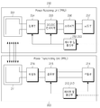
도 5의 제어 방법은 도 6을 참조하여 더욱 상세하게 설명하도록 한다. 도 6은 도 5의 실시예에 따른 무선 전력 송신기가 인가하는 전력량의 시간 축에 대한 그래프이다.The control method of FIG. 5 will be described in more detail with reference to FIG. FIG. 6 is a time-axis graph of the amount of power applied by the wireless power transmitter according to the embodiment of FIG.
도 5를 참조하면, 무선 전력 송신기는 구동을 개시할 수 있다(S501). 아울러, 무선 전력 송신기는 초기설정을 리셋할 수 있다(S503). 무선 전력 송신기는 전력 절약 모드에 진입할 수 있다(S505). 여기서, 전력 절약 모드는 무선 전력 송신기가 전력 송신부에 전력량이 상이한 이종의 전력을 인가하는 구간일 수 있다. 예를 들어, 무선 전력 송신기는 도 6에서의 제 2 검출 전력(601, 602) 및 제 3 검출 전력(611, 612,613, 614, 615)을 전력 송신부에 인가하는 구간일 수 있다. 여기서, 무선 전력 송신기는 제 2 검출 전력(601, 602)을 제 2 주기로 주기적으로 인가할 수 있고, 제 2 검출 전력(601, 602)을 인가하는 경우에는 제 2 기간 동안 인가할 수 있다.Referring to FIG. 5, the wireless power transmitter can start driving (S501). In addition, the wireless power transmitter may reset the initial setting (S503). The wireless power transmitter may enter a power saving mode (S505). Here, the power saving mode may be a period in which the wireless power transmitter applies different types of power having different amounts of power to the power transmission unit. For example, the wireless power transmitter may be a section that applies the second detected
무선 전력 송신기는 제 3 검출 전력(611, 612, 613, 614, 615)을 제 3 주기로 주기적으로 인가할 수 있고, 제 3 검출 전력(611, 612, 613, 614, 615)을 인가하는 경우에는 제 3 기간 동안 인가할 수 있다. 한편, 제 3 검출 전력(611, 612, 613, 614, 615)의 각각의 전력 값은 상이한 것과 같이 도시되어 있지만, 제 3 검출 전력(611, 612,613, 614, 615)의 각각의 전력 값은 상이할 수도 있고, 또는 동일할 수도 있다.The wireless power transmitter can periodically apply the third detected
무선 전력 송신기는 제 3 검출 전력(611)을 출력한 이후에 동일한 크기의 전력량을 가지는 제 3 검출 전력(612)을 출력할 수 있다. 상기와 같이 무선 전력 송신기가 동일한 크기의 제 3 검출 전력을 출력하는 경우, 제 3검출 전력의 전력량은 가장 소형의 무선 전력 수신기, 예를 들어 카테고리 1의 무선 전력 수신기를 검출할 수 있는 전력량을 가질 수 있다.The wireless power transmitter can output the third detected
무선 전력 송신기는 제 3 검출 전력(611)을 출력한 이후에 상한 크기의 전력량을 가지는 제 3 검출 전력(612)을 출력할 수 있다. 무선 전력 송신기가 상이한 크기의 제 3 검출 전력을 출력하는 경우, 제 3 검출 전력의 전력량 각각은 카테고리 1 내지 5의 무선 전력 수신기를 검출할 수 있는 전력량일 수 있다. 예를 들어, 제 3 검출 전력(611)는 카테고리 5의 무선 전력 수신기를 검출할 수 있는 전력량을 가질 수 있고, 제 3 검출 전력(612)는 카테고리 3의 무선 전력 수신기를 검출할 수 있는 전력량을 가질 수 있으며, 제 3 검출 전력(613)는 카테고리 1의 무선 전력 수신기를 검출할 수 있는 전력량을 가질 수 있다.The wireless power transmitter can output the
한편, 제 2 검출 전력(601, 602)은 무선 전력 수신기를 구동시킬 수 있는 전력일 수 있다. 보다 상세하게는, 제2 검출 전력(601, 602)은 무선 전력 수신기의 제어부 및 통신부를 구동시킬 수 있는 전력량을 가질 수 있다.On the other hand, the second detected
무선 전력 송신기는 제 2 검출 전력(601, 602) 및 제 3 검출 전력(611, 612,613, 614, 615)을 전력 수신부로 각각 제 2 주기 및 제 3 주기로 인가할 수 있다. 무선 전력 송신기 상에 무선 전력 수신기가 배치되는 경우, 무선 전력 송신기의 일 지점에서 바라보는 임피던스가 변경될 수 있다. 무선 전력 송신기는 제 2 검출 전력(601, 602) 및 제 3 검출 전력(611,612,613,614,615)이 인가되는 중 임피던스 변경을 검출할 수 있다. 예를 들어, 무선 전력 송신기는 제 3 검출 전력(615)을 인가하는 중, 임피던스가 변경되는 것을 검출할 수 있다. 이에 따라, 무선 전력 송신기는 물체를 검출할 수 있다(S507). 물체가 검출되지 않는 경우에는(S507-N), 무선 전력 송신기는 이종의 전력을 주기적으로 인가하는 전력 절약 모드를 유지할 수 있다(S505).The wireless power transmitter may apply the second detected
한편, 임피던스가 변경되어 물체가 검출되는 경우에는(S507-Y), 무선 전력 송신기는 저전력 모드로 진입할 수 있다. 여기서, 저전력 모드는 무선 전력 송신기가 무선 전력 수신기의 제어부 및 통신부를 구동시킬 수 있는 전력량을 가진 구동 전력을 인가하는 모드이다. 예를 들어, 도 6에 도시된 바와 같이, 무선 전력 송신기는 구동 전력(620)을 전력 송신부에 인가할 수 있다. 무선 전력 수신기는 구동 전력(620)을 수신하여 제어부 및 통신부를 구동할 수 있다. 무선 전력 수신기는 구동 전력(620)에 기초하여 무선 전력 송신기와 소정의 방식에 기초하여 통신을 수행할 수 있다. 예를 들어, 무선 전력 수신기는 인증에 요구되는 데이터를 송수신할 수 있고, 이에 기초하여 무선 전력 송신기가 관장하는 무선 전력 네트워크에 가입할 수 있다. 다만, 무선 전력 수신기가 아닌 이물질이 배치되는 경우에는, 데이터 송수신이 수행될 수 없다. 이에 따라, 무선 전력 송신기는 배치된 물체가 이물질인지 여부를 결정할 수 있다(S511). 예를 들어, 무선 전력 송신기는 기 설정된 시간 동안 물체로부터 응답을 수신하지 못한 경우, 물체를 이물질로 결정할 수 있다.On the other hand, if the impedance is changed and an object is detected (S507-Y), the wireless power transmitter can enter the low power mode. Here, the low power mode is a mode in which the wireless power transmitter applies driving power having an amount of power capable of driving the control unit and the communication unit of the wireless power receiver. For example, as shown in FIG. 6, the wireless power transmitter may apply the driving
이물질로 결정된 경우에는(S511-Y), 무선 전력 송신기는 랫치 실패 모드로 진입할 수 있다. 예를 들면, 무선 전력 송신기는 도 6에서의 제 1 전력(631 내지 634)을 제 1 주기로 주기적으로 인가할 수 있다. 무선 전력 송신기는 제 1 전력을 인가하는 중에 임피던스 변경을 검출할 수 있다. 예를 들어, 이물질이 회수되는 경우에는 임피던스 변경을 검출할 수 있으며, 무선 전력 송신기는 이물질이 회수된 것으로 판단할 수 있다. 또는, 이물질이 회수되지 않는 경우에는 무선 전력 송신기는 임피던스 변경을 검출할 수 없고, 무선 전력 송신기는 이물질이 회수되지 않은 것으로 판단할 수 있다. 이물질이 회수되지 않는 경우에는, 무선 전력 송신기는 램프 및 경고음 중 적어도 하나를 출력하여 현재의 무선 전력 송신기의 상태가 에러 상태임을 사용자에게 알릴 수 있다. 이에 따라, 무선 전력 송신기는 램프 및 경고음 중 적어도 하나를 출력하는 출력부를 포함할 수 있다.If determined to be foreign (S511-Y), the wireless power transmitter may enter the latch failure mode. For example, the wireless power transmitter may periodically apply the first power (631 to 634) in Fig. 6 in a first period. The wireless power transmitter may detect an impedance change while applying the first power. For example, if a foreign object is recovered, an impedance change can be detected and the wireless power transmitter can determine that the foreign object has been recovered. Alternatively, if the foreign object is not recovered, the wireless power transmitter can not detect the impedance change, and the wireless power transmitter can determine that the foreign matter has not been recovered. If the foreign object is not recovered, the wireless power transmitter may output at least one of a lamp and an alarm to inform the user that the status of the current wireless power transmitter is an error condition. Accordingly, the wireless power transmitter may include an output for outputting at least one of a lamp and an alarm sound.
이물질이 회수되지 않은 것으로 판단되는 경우(S515-N), 무선 전력 송신기는 랫치 실패 모드를 유지할 수 있다(S513). 한편, 이물질이 회수된 것으로 판단되는 경우(S515-Y), 무선 전력 송신기는 전력 절약 모드로 재진입할 수 있다(S517). 예를 들어, 무선 전력 송신기는 제 2 전력(651,652) 및 제 3 전력(661 내지 665)을 인가할 수 있다. If it is determined that the foreign substance is not recovered (S515-N), the wireless power transmitter can maintain the latch failure mode (S513). On the other hand, if it is determined that the foreign substance is recovered (S515-Y), the wireless power transmitter can re-enter the power saving mode (S517). For example, the wireless power transmitter may apply the second power (651, 652) and the third power (661-665).
한편, 도 5 및 6과 관련한 경우, 무선 전력 수신기의 배치에 기인한 임피던스 변경이 크지 않은 경우에는 무선 전력 수신기 검출이 어려울 수 있다.
5 and 6, detection of the wireless power receiver may be difficult if the impedance change due to the placement of the wireless power receiver is not large.
도 7은 본 발명의 다른 실시예에 따른 무선 전력 송신기 및 무선 전력 수신기의 블록도이다.7 is a block diagram of a wireless power transmitter and a wireless power receiver in accordance with another embodiment of the present invention.
도 7을 참조하면, 무선 전력 송신기(700)는 시스템 제어부(710) 및 적어도 하나의 전력 송신부(720, 730)를 포함할 수 있고, 전력 송신부(720, 730)는 파워 변환부(721, 731)와 통신 및 제어부(723, 733)를 포함할 수 있다. 또한, 무선 전력 수신기(750)는 전력 수신부(751) 및 로드부(755)를 포함할 수 있고, 전력 수신부(751)는 파워 픽업부(752)와 통신 및 제어부(753)를 포함할 수 있다.7, the
파워 변환부(721, 731)는 전기적 전력을 무선 전력으로 변환하고, 적어도 하나의 무선 전력 수신기(750)의 수신부(752)에 포함된 파워 픽업부(752)로 무선 전력을 전송할 수 있다. 파워 변환부(721, 731)는 무선 전력을 송신하는 자기 유도 방식의 1차 코일(Primary coil)이 포함될 수 있다.The
파워 픽업부(752)는 무선 전력을 파워 변환부(721, 731)로부터 무선 전력을 수신하고, 수신된 무선 전력을 전기적 전력으로 변환할 수 있으며, 무선 전력을 수신하는 자기 유도 방식의 2차 코일(Secondary Coil)이 포함될 수 있다. 예를 들어, 파워 변환부(721, 731) 및 파워 픽업부(752)는 1차 코일과 2차 코일을 수평적 정렬 상태 및 수직적 정렬 중 적어도 하나의 상태로 유지하여 무선 전력을 송수신할 수 있다. 1차 코일은 권선(Wire-wound) 유형의 코일일 수 있고, 적어도 하나의 코일로 이루어진 코일 어레이일 수 있으며, 2차 코일과 함께 코어리스(Coreless) 공진 변압기 부분을 형성할 수 있다. The
한편, 무선 전력 송신기(700)는 는 무선 전력을 전송하기 위하여 평평한 표면(Flat Surface) 형태의 인터페이스 표면(Interface Surface)(미도시)을 더 포함할 수 있다. 인터페이스 표면의 상부에는 적어도 하나의 무선 전력 수신기(750)가 놓일 수 있고, 인터페이스 표면의 하부에는 1차 코일이 구비될 수 있다. 이 때, 인터페이스 표면의 하부에 장착되는 1차 코일과 인터페이스 표면의 상부에 위치한 무선 전력 수신기(750)의 2차 코일 사이에 수직 공간(Vertical Spacing)이 작게 형성하여 1차 코일과 2차 코일 간의 유도 결합이 이루어질 수 있다. 이하, 1차 코일에 대하여 상세히 설명하기로 한다.
Meanwhile, the
도 8은 2개의 1차 코일을 구성하는 예를 도시한 도면이고, 도 9는 3개의 1차 코일을 구성하는 예를 도시한 도면이다.Fig. 8 is a view showing an example of constituting two primary coils, and Fig. 9 is a view showing an example of constituting three primary coils.
도 8을 참조하면, 2개의 1차 코일은 권선 유형의 코일일 수 있고, 권선 유형의 코일은 115가닥과 0.08mm 직경으로 이루어진 리츠 와이어(Litz Wire)로 구성될 수 있다. 또한, 2개의 1차 코일은 레이스트렉(Racetrack-like) 형상일 수 있고, 단일 층으로 구성될 수 있다. 또한, 2개의 1차 코일의 파라미터는 do 및 dh를 포함할 수 있고, do는 1차 코일의 외경이고, dh는 2개의 1차 코일의 센터간의 거리일 수 있다.Referring to Fig. 8, the two primary coils may be coils of the winding type, and the coils of the winding type may be composed of Litz Wire consisting of 115 strands and 0.08 mm diameter. In addition, the two primary coils can be of the Racetrack-like shape and can be composed of a single layer. Also, the parameters of the two primary coils may include d o and d h , d o is the outer diameter of the primary coil, and d h may be the distance between the centers of the two primary coils.
도 9를 참조하면, 3개의 1차 코일은 105가닥과 0.08mm 직경으로 이루어진 리츠 와이어로 구성될 수 있다. 또한, 3개의 1차 코일은 직사각형(Rectangular) 형상일 수 있고, 단일 층으로 구성될 수 있다. 또한, 3개의 1차 코일의 파라미터는 doe 및 doo를 포함할 수 있고, doe는 1번째 1차 코일의 센터와 2번째 1차 코일의 센터간의 거리이며, doo는 1번째 1차 코일의 센터와 3번째 1차 코일의 센터간의 거리일 수 있다.Referring to FIG. 9, the three primary coils may be composed of 105 strands and a Litz wire of 0.08 mm diameter. In addition, the three primary coils may be in a rectangular shape and may be composed of a single layer. The parameters of the three primary coils may include d oe and d oo , where d oe is the distance between the center of the first primary coil and the center of the second primary coil, and d oo is the first primary The distance between the center of the coil and the center of the third primary coil.
다시 도 7을 참조하면, 통신 및 제어부(723, 733)는 적어도 하나의 전력 수신부(752)와의 통신을 수행할 수 있다. 또한, 통신 및 제어부(723, 733)는 전력 수신부(752)로부터 필요한 무선 전력에 대한 요청 메시지를 수신할 수 있고, 이에 따라 통신 및 제어부(723, 733)는 전력 수신부(752)에게 요청한 무선 전력이 전송되도록 파워 변환부(721)를 제어할 수 있다.Referring again to FIG. 7, the communication and
파워 픽업부(752)는 파워 변환부(721)로부터 무선 전력을 수신할 수 있고, 로드부(755)는 수신된 무선 전력 로드하여 배터리를 충전할 수 있다. 통신 및 제어부(753)는 송신부(720, 730)와의 통신을 수행할 수 있고, 송신부로부터(720, 730) 무선 전력이 수신되도록 제어할 수 있다. 이하, 도 10을 참조하여, 전력 송신부(720, 730)의 상세한 구성을 설명하기로 한다.
The
도 10은 도 7의 실시예에 따른 무선 전력 송신기에 대한 전력 송신부의 상세 블록도이다.10 is a detailed block diagram of a power transmitter for a wireless power transmitter according to the embodiment of FIG.
도 10을 참조하면, 전력 송신부(720, 730)는 통신 및 제어부(721) 및 파워 변환부(723)가 포함될 수 있고, 파워 변환부(723)는 인버터(723a), 임피던스 매칭부(723b), 센싱부(723c), 멀티플렉서(723d) 및 1차 코일 어레이(723e)를 포함할 수 있다.10, the
파워 변환부(723)에서 인버터(723a)는 직류(DC, Digital Current) 입력을 교류(AC, Analog Current) 웨이브폼으로 변환할 수 있고, 임피던스 매칭부(723b)는 공진 회로와 1차 코일 어레이(723e) 간의 연결이 되도록 매칭할 수 있다. 또한, 센싱부는 공진 회로와 1차 코일 어레이(723e) 간의 전류와 전압을 감지하여 모니터링 할 수 있고, 멀티플렉서(723d)는 전력 수신기(751)의 위치에 따라 적절한 1차 코일을 연결/비연결할 수 있다.The inverter 723a in the
통신 및 제어부(721)는 전력 수신기(751)로부터 무선 전력에 대한 요청 메시지를 수신할 수 있고, 멀티플렉서(723d)를 통하여 적절한 1차 코일 어레이에 대한 연결을 제어할 수 있다. 또한, 통신 및 제어부(721)는 전력 제어 알고리즘 및 프로토콜을 실행하여 무선 전력량이 조절되도록 인버터(723a)를 제어하고, 무선 전력을 전력 수신기(751)로 전송되도록 1차 코일 어레이(723e)를 제어할 수 있다. 이하, 도 11을 참조하여 전력 송신부(720, 730)의 1차 코일 어레이(723e)를 설명하기로 한다.
The communication and
도 11은 전력 송신부에 대한 1차 코일 어레이를 구성하는 예를 도시한 도면이다. 11 is a diagram showing an example of configuring a primary coil array for a power transmission unit.
도 11에서 (a)는 1차 코일 레이어의 상부 단층을 도시한 예이고, (b)는 1차 코일 어레이의 일 측면을 도시한 예이며, (c)는 1차 코일 어레이의 상부 단층을 도시한 예이다.Fig. 11 (a) is an example showing an upper single layer of the primary coil layer, Fig. 11 (b) is an example showing one side of the primary coil array, It is an example.
1차 코일은 원형 형상 및 단일 층으로 구성될 수 있고, 1차 코일 어레이는 육각형 격자의 영역을 갖는 복수의 1차 코일 레이어들로 구성될 수 있다.The primary coil may be composed of a circular shape and a single layer, and the primary coil array may be composed of a plurality of primary coil layers having a region of a hexagonal lattice.
도 11을 참조하면, 1차 코일 어레이 파라미터는 do, di, dc, da, dh, t2 및 t3를 포함할 수 있다. do는 1차 코일 레이어의 외경, di는 1차 코일 레이어의 내경, dc는 1차 코일 레이어의 두께, da는 1차 코일 어레이의 두께, dh는 인접하는 1차 코일 레이어들간의 센터 거리, t2는 2번째 1차 코일 레이어 어레이의 오프셋 및 t3는 3번째 1차 코일 레이어 어레이의 오프셋으로 나타낼 수 있다.Referring to FIG. 11, the primary coil array parameters may include d o , d i , d c , d a , d h , t 2, and t 3 . d o is the outer diameter of the primary coil layer, d i is the inner diameter of the primary coil layer, d c is the thickness of the primary coil layer, d a is the thickness of the primary coil array, d h is the distance between the adjacent primary coil layers T 2 is the offset of the second primary coil layer array, and t 3 is the offset of the third primary coil layer array.
다시 도 7을 참조하면, 시스템 제어부(710)는 적어도 하나의 무선 전력 수신기(750)와의 무선 전력 전송을 제어할 수 있다. 따라서, 무선 전력 송신기(700)는 복수의 무선 전력 수신기(미도시)에게 무선 전력을 전송할 수 있다. 이하 도 12를 참조하여 무선 전력 송신기(700)의 제어 동작을 수행하는 시스템 제어부(710)를 상세히 설명하기로 한다.
Referring again to FIG. 7,
도 12는 무선 전력 송신기의 제어 동작을 설명하기 위한 흐름도이다.12 is a flowchart for explaining the control operation of the wireless power transmitter.
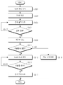
도 12를 참조하면, 무선 전력 송신기의 제어 동작은 선택(Selection)하는 단계, 핑(Ping)하는 단계, 식별(Identification)과 설정(Configuration)하는 단계 및 전력 전송(Power Transfer)하는 단계를 포함할 수 있다.Referring to FIG. 12, the control operation of the wireless power transmitter includes a step of selection, a step of pinging, an step of identification and a step of configuration, and a step of power transfer .
선택하는 단계는 무선 전력 수신기의 위치 및 제거에 대한 인터페이스 표면을 모니터링 할 수 있다. 예를 들어, 선택하는 단계는 자유위치에 존재하는 적어도 하나의 무선 전력 수신기를 발견하여 모니터링 할 수 있고, 무선 전력 수신기가 아닌 개체(예를 들어, 이물질, 열쇠 및 동전 등)를 구별할 수 있다.The selecting can monitor the location of the wireless power receiver and the interface surface for removal. For example, the selecting may be to discover and monitor at least one wireless power receiver that is in a free position and to identify an entity (e.g., foreign object, key, coin, etc.) that is not a wireless power receiver .
또한, 무선 전력 수신기에 대한 정보가 부족한 경우, 선택하는 단계는 핑하는 단계 및 식별과 설정하는 단계를 반복적으로 수행하여 관련 정보를 선택할 수 있다. 또한, 선택하는 단계는 무선 전력 수신기에 무선 전력을 전송할 1차 코일을 선택할 수 있다. 또한, 선택하는 단계는 1차 코일을 선택하지 않는 경우 대기 모드로 전환할 수 있다.In addition, when the information on the wireless power receiver is insufficient, the selecting step may repeatedly perform the pinging step and the identifying and setting step to select the related information. In addition, the selecting may select a primary coil to transmit wireless power to the wireless power receiver. Also, the selecting may switch to the standby mode if the primary coil is not selected.
핑하는 단계는 디지털 핑을 실행하고, 무선 전력 수신기에 대한 응답을 수신되도록 대기할 수 있다. 또한, 핑하는 단계는 무선 전력 수신기를 발견하는 경우, 디지털 핑을 연장할 수 있고, 디지털 핑의 레벨을 유지할 수 있다. 또한, 디지털 핑을 연장하지 않는 경우에 핑하는 단계는 다시 선택하는 단계로 돌아갈 수 있다.The step of pinging may execute a digital ping and wait for a response to the wireless power receiver to be received. In addition, the step of pinging may extend the digital ping and maintain the level of the digital ping when discovering the wireless power receiver. Also, in the case where the digital ping is not extended, the pinging step may be returned to the step of selecting again.
식별과 설정하는 단계는 선택된 무선 전력 수신기를 식별하고, 무선 전력 수신기가 요청한 무선 전력량 설정 정보를 획득할 수 있다. 또한, 식별과 설정하는 단계는 연장된 디지털 핑을 종료되도록 설정할 수 있고, 다른 무선 전력 수신기를 발견하기 위해 다시 선택하는 단계로 돌아갈 수 있다.The identifying and setting step may identify the selected wireless power receiver and obtain the requested wireless power setting information from the wireless power receiver. In addition, the identifying and setting step can be set to terminate the extended digital ping and return to the step of reselecting to find another wireless power receiver.
전력 전송하는 단계는 식별된 무선 전력 수신기에게 요청한 무선 전력량을 전송할 수 있고, 제어 데이터를 기반으로 1차 코일의 전류를 조절할 수 있다. 또한, 식별된 무선 전력 수신기로 요청한 무선 전력량에 대한 전송이 완료되면, 전력 전송하는 단계는 식별된 무선 전력 수신기에 대한 무선 전력 전송을 중단할 수 있다.
The power transmitting step may transmit the requested amount of radio power to the identified radio power receiver and may adjust the current of the primary coil based on the control data. Also, once transmission to the identified wireless power receiver has been completed for the requested amount of wireless power, the power transmitting step may stop the wireless power transmission to the identified wireless power receiver.
도 13은 일 실시예에 따른 전력 송신부의 구성을 설명하기 위한 도면이다.13 is a diagram for explaining a configuration of a power transmission unit according to an embodiment.
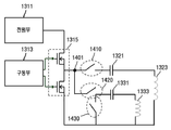
도 13에 도시된 전력 송신부(1300)는 인버터를 포함하는 전력 변환부(1310), 자기 유도 방식으로 전력을 전송하기 위한 자기 유도 송신부(1320) 및 자기 공진 방식으로 전력을 전송하기 위한 자기 공진 송신부(1330)를 포함할 수 있다. The
자기 유도 송신부(1320) 및 자기 공진 송신부(1330)는 시분할 방식으로 온/오프 되거나 동시에 온/오프 될 수 있다. 따라서, 전력 송신부(1300)는 자기 유도 방식의 무선 전력 수신 장치 및 자기 공진 방식의 무선 전력 수신 장치로 동시에 전력을 전송할 수 있다.
The
도 14는 도 13의 전력변환부(1300)에 포함된 인버터의 출력단과 자기 유도 송신부(1320) 및 자기 공진 송신부(1330)의 연결관계의 예를 나타내는 도면이다. 14 is a diagram showing an example of the connection relationship between the output terminal of the inverter included in the
도 13 및 도 14를 참조하면, 전력 송신부(1300)는 제1 스위치(1410), 제2 스위치(1420) 및 제3 스위치(1430)를 제어하여 자기 유도 송신 모드, 자기 공진 송신 모드 및 하이브리드 모드로 동작할 수 있다. 이때, 하이브리드 모드는 자기 유도 방식의 전력 전송 및 자기 공진 방식의 전력 전송을 동시에 수행하는 모드일 수 있다.13 and 14, the
무선 전력 전송 장치는 전력 송신부(1300)의 동작 모드를 결정하기 위하여, 무선 전력 수신 장치와 통신을 수행하거나 임피던스의 변화를 측정할 수 있고, 평상시 또는 무선 전력 수신 장치의 종류가 명확하지 않은 경우 하이브리드 모드로 동작할 수 도 있다. The wireless power transmission apparatus can communicate with the wireless power receiving apparatus or measure a change in impedance to determine the operation mode of the
전원부(1311)는 직류 전압을 스위치부(1315)로 인가하고, 구동부(1313)는 스위치부(1315)를 제어하여 인버터 출력단(1401)으로 교류 전압을 출력한다. The
도 13의 자기 유도 송신부(1320)는 제1 커패시터(1321) 및 제1 인덕터(1323)를 포함할 수 있다. The
도 13의 자기 공진 송신부(1330)는 제2 커패시터(1331) 및 제2 인덕터(1333)를 포함할 수 있다.The self-
제1 스위치(1410)의 일단은 인버터 출력단(1401)에 연결되고 타단은 제1 커패시터(1321)에 연결될 수 있다. One end of the
제2 스위치(1420)의 일단은 인버터 출력단(1401)에 연결되고 타단은 제2 커패시터(1331)에 연결될 수 있다.One end of the
자기 유도 송신 모드에서 제1 스위치(1410)는 온 되고, 제2 스위치(1420) 및 제3 스위치(1430)는 오프 될 수 있다. In the magnetic induction transmission mode, the
제1 자기 공진 송신 모드에서 제1 스위치(1410)는 오프 되고, 제2 스위치(1420)는 온 될 수 있다. In the first self-resonant transmission mode, the
제2 자기 공진 송신 모드에서 제1 스위치(1410)는 온 되고, 제3 스위치(1430)는 온 될 수 있다.In the second self-resonant transmission mode, the
이때, 전력 송신부(1300)는 제3 스위치(1430)를 온 시키는 경우 제1 스위치를 항상 온 시키고 제2 스위치(1420)를 항상 오프시킨다. At this time, when the
자기 공진 송신 모드에서 제3 스위치(1430)가 온 되는 경우, 제2 커패시터(1331) 및 제2 인덕터(1333)는 폐루프를 형성한다. 이때, 폐루프를 공진기라 칭할 수 있다. 제2 자기 공진 송신 모드에서 에너지는 제1 인덕터(1323)로부터 제2 인덕터로(1333) 유도 된후, 공진기를 통해 무선 전력 수신 장치로 전달 될 수 있다. When the
제2 자기 공진 송신 모드에서 제2 커패시터(1331) 및 제2 인덕터(1333)는 공진기로 동작하기 때문에 전체 시스템의 고유 공진 주파수에 영향을 주지 않는다. 따라서, 제2 자기 공진 송신 모드에서 에너지는 제1 자기 공진 송신 모드에 비해 높은 효율로 무선 전력 수신 장치에 전달될 수 있다. 따라서, 도 14에 도시된 제2 스위치(1320)는 제거 될 수 도 있다. In the second self-resonant transmission mode, since the
전력 송신부(1300)는 제1 스위치(1410) 및 제2 스위치(1320)를 시분할로 온/오프 시킴으로써, 하이브리드 모드로 동작할 수 있다. 또한, 전력 송신부(1300)는 제1 스위치(1410)가 항시 온 된 상태에서 제3 스위치(1430)를 시분할로 온/오프 시킴으로써, 하이브리드 모드로 동작할 수 있다.The
한편, 도 14에서 제1 커패시터(1321) 및 제1 인덕터(1323)는 유도 코일의 등가회로 일 수 있고, 각각 제1 커패시턴스 및 제2 인덕턴스라 칭할 수 도 있다. 마찬가지로 제2 커패시터(1331) 및 제2 인덕터(1333)는 공진 코일의 등가 회로 일 수 있고, 각각 제2 커패시턴스 및 제2 인덕턴스라 칭할 수 도 있다.
14, the
도 15는 도 13의 자기 유도 송신부(1320) 및 자기 공진 송신부(1330)의 구성 예를 나타낸다. 15 shows a configuration example of the self-
도 15를 참조하면, 자기 유도 송신부(1320)는 단일 코일 또는 코일 어레이(1520)로 구성되고, 자기 공진 송신부(1330)는 코일 어레이(1520)를 감싸는 형태의 공진 코일(1530)로 구성될 수 있다. 15, the
코일 어레이(1520)는 복수의 코일 셀들(1521, 1523, 1525, 1527)을 포함할 수 있다. 물론, 코일 어레이(1520)는 도 9 또는 도 11과 같이 구성된 복수의 1차 코일들을 포함할 수 있다. The
자기 유도 송신 모드에서 무선 전력 수신 장치의 요구 전력량에 따라 복수의 코일 셀들 중 일부 만 온 되거나 전부 온 될 수 도 있다.In the magnetic induction transmission mode, only a part of the plurality of coil cells may be turned on or all in accordance with the required power amount of the wireless power receiving apparatus.
또한, 코일 어레이(1520)가 복수의 코일 셀들로 구성되는 경우, 제2 자기 공진 송신 모드에서 무선 전력 수신 장치의 요구 전력량에 따라 복수의 코일 셀들 중 일부 만 온 되거나 전부 온 될 수 도 있다.
Further, when the
도 16은 일 실시예에 따른 도 11의 1차 코일 어레이를 제어 방법을 설명하기 위한 도면이다. 16 is a view for explaining a method of controlling the primary coil array of FIG. 11 according to an embodiment.
도 12에서 설명된 바와 같이, 무선 전력 전송 장치는 식별(Identification)과 설정(Configuration)하는 단계 이후, 전력 전송(Power Transfer)하는 단계로 동작할 수 있다. As described in FIG. 12, the wireless power transmission apparatus can operate as a step of power transfer after the step of Identification and Configuration.
이때, 전력 전송(Power Transfer)하는 단계에서 새로운 무선 전력 수신기가 등장하거나, 이물질(Foreign object)이 존재하게 되는 경우 1차 코일 어레이의 동작을 제어하는 방법이 필요하다. In this case, there is a need for a method of controlling the operation of the primary coil array when a new radio power receiver appears or a foreign object is present in the power transfer stage.
도 16을 참조하면, 일 실시예에 따른 1차 코일 어레이(1600)는 복수의 1차 코일들 및 복수의 센서(1640)들로 구성될 수 있다. Referring to FIG. 16, a
이때, 센서(1640)는 압력 센서일 수 도 있고, 온도 센서일 수 도 있다. 다시 말해, 1차 코일 어레이(1600)는 복수의 압력 센서들 및 복수의 온도 센서들을 포함할 수 도 있다. At this time, the
센서(1640)는 1차 코일 어레이(1600)의 복수 위치에 구비될 수 있다. 따라서, 무선 전력 전송 장치는 센서(1640)를 통해 압력 변화에 의한 특정 위치의 새로운 물체 감지 및 특정 위치의 온도 변화를 감지할 수 있다. The
예를 들어, 제1 시간 구간에서 제1 무선 전력 수신 장치(1610)로 전력을 전송하는 " Power Transfer" 단계에서 새로운 무선 전력 수신 장치(1620)가 1차 코일 어레이(1600)의 특정 위치하게 되면, 해당 위치의 압력 센서의 센싱 값이 변화할 수 있다. For example, when a new wireless
이때, 무선 전력 전송 장치는 " Power Transfer" 단계를 중단하고, 다시 식별(Identification)과 설정(Configuration)하는 단계로 동작할 수 있다. At this time, the wireless power transmission apparatus can stop the "Power Transfer" step, and can operate as a step of identification and setting again.
한편, " Power Transfer" 단계에서 이물질(1630)이 구동되고 있는 1차 코일들 위에 또는 구동되고 있지 않는 1차 코일들 위에 위치하게 될 수 있다. On the other hand, in the "Power Transfer" step, the
이때, 무선 전력 전송 장치는 온도 센서를 통해 특정 위치의 온도가 상승하는 것을 감지할 수 있다. 만일 기 설정된 임계치 이상 온도가 상승하게 되면, 해당 온도 센서 주변의 구동되는 1차 코일들(예를 들어, 온도 센서 주변의 4개 코일)을 오프 시켜 구동을 정지 시킬 수 도 있다. At this time, the wireless power transmission apparatus can detect that the temperature of the specific position rises through the temperature sensor. If the temperature exceeds the preset threshold value, the primary coils driven around the temperature sensor (for example, four coils around the temperature sensor) may be turned off to stop the driving.
또한, 온도 상승을 감지한 온도 센서 주변의 1차 코일들을 오프 시킨 경우에도 온도가 임계치 이하로 하강하지 않거나 상승하면, 전체 1차 코일 어레이의 동작을 일시 정지 시킬 수 도 있다. 또한, 이물질을 감지하기 위해 " Power Transfer" 단계를 중단하고, 다시 식별(Identification)과 설정(Configuration)하는 단계로 동작할 수 있다.Further, even when the primary coils around the temperature sensor that senses the temperature rise are turned off, the operation of the entire primary coil array may be temporarily stopped if the temperature does not fall below the threshold value or rises. Also, it is possible to stop the "Power Transfer" step to detect a foreign object, and to operate again to identify and configure the foreign object.
일 실시예에서, 온도 센서는 전체 1차 코일 어레이(1600)의 3군데 또는 4군데에만 구비될 수 있다. 3개의 온도 센서가 구비된 경우 3개의 센서에서 측정되는 온도의 차이 값을 이용하여 어느 위치의 셀에서 온도가 임계치 이상으로 상승한 것인지를 판단할 수 도 있다.In one embodiment, the temperature sensors may be provided at only three or four locations of the entire
예를 들어, 제1 온도 센서, 제2 온도 센서 및 제3 온도 센서가 삼각형 형태로 배치되고, 각각의 센싱 값이 A, B, C일 때, A-B, B-C, C-A의 값 또는 이들의 절대값에 따라 기 측정된 값을 테이블로 저장해 두고, A-B가 가장 큰 값이고 A가 B보다 크고 임계값 보다 일정 값 이상 큰 값이면 A주변의 1차 코일들을 오프 시킬 수 도 있다. 또는, A가 25, B가 24.5, C가 24.6인 경우 A와 C사이의 셀들 중 B로부터 특정 거리 이상에 있는 셀들을 오프 시키도록 설정하는 것도 가능하다.
For example, when the first temperature sensor, the second temperature sensor and the third temperature sensor are arranged in a triangular shape and the respective sensing values are A, B, and C, the values of AB, BC, If AB is the largest value and A is greater than B and greater than the threshold value by more than a certain value, the primary coils around A may be turned off. Alternatively, when A is 25, B is 24.5, and C is 24.6, it is also possible to set off cells located at a certain distance or more from B among cells between A and C.
한편, 1차 코일 어레이(1600)에 포함된 각각의 1차 코일 당 전송 가능한 전력은 온도 상승, 전자파 문제 등으로 인해 제한될 수 있다. 따라서, 무선 전력 전송 장치는 무선 전력 수신 장치에 전력을 전달하기 위해, 구동 시킬 적어도 하나의 1차 코일을 결정하고, 구동 시킬 1차 코일의 최대 전송 전력량이 무선 전력 수신 장치의 요구 전력량 보다 큰 경우에만 전력 전송을 개시할 수 도 있다. On the other hand, the transferable power per primary coil included in the
예를 들어, 무선 전력 전송 장치는 통신을 통해 무선 전력 수신 장치의 위치 및 요구 전력량 Prequest을 파악하고, 해당 위치에서 구동시킬 1차 코일들 전체의 전송 가능 전력량 Psum을 계산할 수 있다. 이때, 구동시킬 1차 코일들의 개수는 무선 전력 수신 장치 하나 당 기 설정된 수로 제한될 수 도 있다. 무선 전력 전송 장치는 Prequest 보다 Psum이 큰 경우에만 해당 1차 코일들을 온 시킬 수 있다.
For example, the wireless power transmission apparatus can calculate the position and required power amount P request of the wireless power receiving apparatus through communication, and calculate the transmittable power amount P sum of the entire primary coils to be driven at the position. At this time, the number of primary coils to be driven may be limited to a predetermined number per one wireless power receiving apparatus. The wireless power transmission apparatus can turn on the primary coils only when P sum is larger than P request .
도 17은 무선 전력 전송 장치의 전력 전송(Power Transfer) 제어 알고리즘을 설명하기 위한 도면이다. 17 is a diagram for explaining a power transfer control algorithm of the wireless power transmission apparatus.
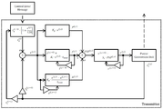
무선 전력 전송 장치의 전력 전송 제어는 PID(Proportional Integral Differential) 알고리즘을 사용하여 진행될 수 있다. 도 17에 도시된 예는 PID 알고리즘의 예를 나타낸다. The power transmission control of the wireless power transmission apparatus can be performed using a PID (Proportional Integral Differential) algorithm. The example shown in Fig. 17 shows an example of a PID algorithm.
자기 유도 방식의 무선 전력 전송 시스템에서, 동작 주파수(Operating Frequency) 제어를 위한 PID 파라미터들의 예는 [표 1]과 같고, 듀티 사이클 제어를 위한 PID 파라미터들의 예는 [표 2]와 같다. In the magnetic induction type wireless power transmission system, examples of PID parameters for operating frequency control are shown in Table 1, and examples of PID parameters for duty cycle control are shown in [Table 2].
[표 1][Table 1]

[표 2][Table 2]
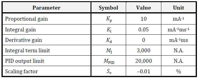
전력 전송(Power Transfer) 단계에서, 무선 전력 전송 장치는 제어 데이터를 기반으로 1차 코일의 전류를 조절할 수 있다. 이때, 1차 코일의 전류 조절은 PID 알고리즘에 기초하여 수행될 수 있다. In the power transfer stage, the wireless power transmission device can regulate the current of the primary coil based on the control data. At this time, current regulation of the primary coil can be performed based on the PID algorithm.
도 17에서, 인덱스 j = 1, 2, 3, …은 "Control Error Packet"들의 시퀀스를 나타내고, "Control Error Packet"은 전력 전송(Power Transfer) 단계에서 무선 전력 전송 장치가 무선 전력 수신 장치로부터 수신하는 메시지를 나타낸다. 17, the index j = 1, 2, 3, ... Indicates a sequence of "Control Error Packets ", and" Control Error Packet " indicates a message received by the wireless power transmission apparatus from the wireless power reception apparatus in a power transfer phase.
무선 전력 전송 장치는 j번째(jth) Control Error Packet을 수신하면, 새로운 1차 셀 전류 ![]()
![]()
[수학식 1][Equation 1]

여기서, ![]()
![]()
![]()
![]()
무선 전력 전송 장치는 수학식 2와 같이 새로운 1차 셀 전류와 실제 1차 셀 전류(actual Primary Cell current)의 차를 계산할 수 있다. The wireless power transmission apparatus can calculate the difference between a new primary cell current and an actual primary cell current as shown in Equation (2).
[수학식 2]&Quot; (2) "

여기서, ![]()
![]()
![]()
![]()
무선 전력 전송 장치는 수학식 3과 같이 Proportional term, Integral term 및 Derivative term을 계산할 수 있다. The wireless power transmission apparatus can calculate the proportional term, the integral term, and the derivative term as shown in Equation (3).
[수학식 3]&Quot; (3) "
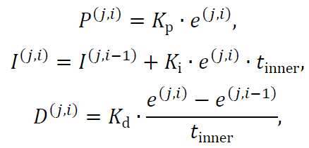
여기서, Kp는 proportional gain이고, Ki는 integral gain이고, Kd는 derivative gain이고, tinner는 PID 알고리즘 루프의 수행에 요구되는 시간을 나타낸다. Where Kp is the proportional gain, Ki is the integral gain, Kd is the derivative gain, and t inner represents the time required to perform the PID algorithm loop.
무선 전력 전송 장치는 수학식 4와 같이 Proportional term, Integral term 및 Derivative term의 합을 계산한다. The wireless power transmission apparatus calculates the sum of the proportional term, the integral term, and the derivative term as shown in Equation (4).
[수학식 4]&Quot; (4) "
![]()
![]()
수학식 4의 계산에 있어서, 무선 전력 전송 장치는 합인 ![]()
![]()
무선 전력 전송 장치는 제어된 변수의 새로운 값를 수학식 5와 같이 계산해야 한다. The wireless power transmission apparatus must calculate a new value of the controlled variable as shown in Equation (5).
[수학식 5]&Quot; (5) "

여기서, ![]()
![]()
제어된 변수의 새로운 값은 파워 컨버전 유닛에 전달된다. 제어된 변수의 새로운 값은 1차 코일의 전류 조절 제한 폭으로 사용될 수 있다. The new value of the controlled variable is passed to the power conversion unit. The new value of the controlled variable can be used as the current regulation limit of the primary coil.
일 실시예에 따르면, 무선 전력 전송 장치는 1차 코일 어레이에 포함된 코일 들 중, 구동되는 코일의 개수에 따라 "PID output limit"의 값을 변경할 수 있다. According to one embodiment, the wireless power transmission apparatus can change the value of the "PID output limit" according to the number of coils driven, among the coils included in the primary coil array.
예를 들어, 무선 전력 전송 장치는 구동 되는 셀 개수가 많을수록 "PID output limit"의 값을 증가시키고, 장치는 구동 되는 셀 개수가 적을수록 "PID output limit"의 값을 감소시킬 수 있다. For example, the wireless power transmission apparatus increases the value of the "PID output limit" as the number of driven cells increases, and decreases the value of the "PID output limit" as the number of driven cells decreases.
따라서, 셀 내의 단일 코일들 각각의 최대 출력 전력을 조절함으로써, 무선 전력 전송 장치의 보호 및 안정적인 전력 전송이 가능하다. Thus, by adjusting the maximum output power of each of the single coils in the cell, the protection and stable power transmission of the wireless power transmission device is possible.
또한, 일 실시예에 따르면, 무선 전력 전송 장치는 전력 제어에 사용되는 전압 및 듀티 등을 구동되는 셀 개수에 따라 제한할 수 도 있다. Also, according to one embodiment, the wireless power transmission device may limit the voltage and duty used in the power control according to the number of cells to be driven.
무선 전력 전송 장치는 1차 코일 어레이에 포함된 코일 들 중, 구동되는 코일의 개수에 따라 1차 코일 어레이에 입력되는 전력을 제한할 수 있다. The wireless power transmission apparatus can limit the power input to the primary coil array depending on the number of coils driven among the coils included in the primary coil array.
또한, 무선 전력 전송 장치는 1차 코일 어레이에 포함된 코일 들 중, 구동되는 코일의 개수에 따라 인버터의 출력 전력을 제한할 수 도 있다.
Further, the wireless power transmission device may limit the output power of the inverter according to the number of coils driven among the coils included in the primary coil array.
도 1 내지 도 7은 자기 공진 방식으로 전력을 전송하기 위한 방식에 대한 설명이고, 도 8 내지 도 12는 자기 유도 방식으로 전력을 전송하기 위한 방식을 나타낸다. 자기 공진 방식으로 전력을 전송하는 예는 종래기술 4에 상세하게 기술되어 있다. 그리고, 도 13내지 도 17은 하이브리드 방식을 나타낸다. Figs. 1 to 7 illustrate a method for transmitting power in a self-resonant manner, and Figs. 8 to 12 show a method for transmitting power in a self-induction manner. An example of transmitting power in a self-resonant manner is described in detail in Prior Art 4. 13 to 17 show the hybrid method.
도 8 내지 도 12는 자기 유도 방식은 로컬 컴퓨팅 환경에서 메인 디바이스와는 독립적으로 마우스 패드에 적용되어 마우스 패드 위의 마우스로 전력을 전송하기 위해 사용될 수 도 있다.
8 to 12, the magnetic induction method may be applied to the mouse pad independently of the main device in a local computing environment, and may be used to transmit power to the mouse on the mouse pad.
도 18 내지 도 21은 일 실시예에 따른 무선 전력 전송 네트워크 환경을 설명하기 위한 도면들이다. 18 to 21 are diagrams for explaining a wireless power transmission network environment according to an embodiment.
도 18을 참조하면, 무선 전력 전송 네트워크(1800)는 메인 디바이스(1810) 및 주변 디바이스들(1821, 1823, 1825)을 포함한다. 18, a wireless
메인 디바이스(1810)는 공진 채널을 통해 주변 디바이스들(1821, 1823, 1825)에게 전력을 공급할 수 있다. 다시 말해, 메인 디바이스(1810)는 근거리(약 1미터) 전송이 가능한 자기 공진 방식을 통해 전력을 전송할 수 있다. The
따라서, 메인 디바이스(1810)는 자기 공진 방식으로 전력을 전송할 수 있는 무선 전력 송신기(1801)를 포함할 수 있다. Thus, the
메인 디바이스(1810)의 전력 전송 커버리지(coverage)에 의해 무선 전력 전송 네트워크가 형성될 수 있다. 전력 전송 커버리지는 종래기술 3 또는 종래기술 5에 개시된 거리 D로 정의될 수 도 있다. A wireless power transmission network may be formed by the power transmission coverage of the
이하, 설명의 편의상 메인 디바이스(1810)의 전력 전송 커버리지(coverage)를 "무선 전력 전송 네트워크의 전력 전송 커버리지"라 칭할 수 도 있다. Hereinafter, for convenience of explanation, the power transmission coverage of the
도 18 내지 도 21에서 참조부호 1830은 메인 디바이스(1810)의 전력 전송 커버리지(coverage)를 나타내고, 예를 들어 참조부호 1830은 무선 전력 송신기(1801)의 최대 송출 전력에 의해 형성되는 전력 전송 커버리지 일수 있다. 18 to 21,
자기 공진 방식의 전력 전송 역시, 인체의 유해성 문제에서 자유롭지 않기 때문에, 사용자(1801)가 무선 전력 전송 네트워크 내에 존재하는 것은 바람직하지 않을 수 있다. 또한, 전력 낭비나 전력 전송 효율성의 문제로 인해, 무선 전력 전송 네트워크의 전력 전송 커버리지의 제어가 필요하다.It may not be desirable for the
예를 들어, 무선 전력 전송 네트워크의 전력 전송 커버리지는 참조부호 1840과 같이 조정되도록 제어될 수 있다. For example, the power transmission coverage of the wireless power transmission network may be controlled to be adjusted, such as 1840.
도 19를 참조하면, 주변 디바이스 3(1825)은 이동 가능한 디바이스일 수 있다. 여기서, 이동 가능한 디바이스는 예를 들어 로컬 컴퓨팅 환경의 마우스와 같이, 사용자의 사용 형태가 주로 디바이스를 주로 움직여가며 사용하는 것일 수 도 있다. 다시 말해, 주변 디바이스들(1821, 1823, 1825)는 모두 이동 가능할 수 있지만, 무선 전력 전송 네트워크에서의 이동 가능하다는 것은 사용되는 형태가 이동성을 갖는 것을 의미할 수 도 있다. 예를 들어, 로컬 컴퓨팅 환경의 모니터 및 키보드는 고정되어 사용되는 것으로 정의되고, 마우스는 이동 가능한 디바이스로 정의될 수 있다. Referring to FIG. 19,
도 19에서 참조부허 1950은 주변 디바이스 3(1825)의 일반적인 이동 범위를 나타낸다. 만일, 주변 디바이스 3(1825)이 이동되어 현재의 무선 전력 전송 커버리지 1840을 벗어난 경우, 무선 전력 전송 커버리지의 재 설정 또는 조정이 필요할 수 있다. 19,
도 20을 참조하면, 주변 디바이스 3(1825)이 이동되어 현재의 무선 전력 전송 커버리지 1840을 벗어난 경우, 또는 주변 디바이스 3(1825)이 이동 가능 범위(1825)를 고려하여 전력 전송 커버리지를 제어할 수 있다. 20, if
도 20에 도시된 예는, 주변 디바이스 3(1825)의 위치 정보가 인식된 경우에 무선 전력 송신기(1801)의 공진기의 지향성을 조정하여 이동 가능 디바이스를 위한 조정된 커버리지(2070)를 형성한 예를 나타낸다. 다시 말해, 공진 채널의 지향성을 조정함으로써, 전력 전송 커버리지가 제어될 수 도 있다. The example shown in FIG. 20 is an example of adjusting the directivity of the resonator of the
이동 가능 디바이스를 위한 조정된 커버리지(2070)는 기 설정된 전력 전송 커버리지(1840)와 함께 형성되거나 독립적으로 형성될 수 도 있다. The coordinated
도 21을 참조하면, 무선 전력 전송 네트워크(1800)는 복수의 섹터들(2110, 2120, 2130)을 포함할 수 있다. Referring to FIG. 21, a wireless
여기서, 복수의 섹터들(2110, 2120, 2130)은 복수의 루프 공진기들 또는 지향성을 가지도록 제작된 특수한 형태의 공진기들에 의해 형성될 수 있다. 복수의 섹터들(2110, 2120, 2130)은 모두 동시에 형성되거나, 주변 디바이스들의 위치에 따라 가변적으로 형성될 수 도 있다. Here, the plurality of
일 실시예에서, 메인 디바이스(1810)는 복수의 섹터들(2110, 2120, 2130)에 대해 순차적으로 송출 전력량 점진적 감소 프로시저를 수행할 수 있다. In one embodiment, the
예를 들어, 제1 섹터(2110)에 대해 송출 전력량 점진적 감소 프로시저를 수행하여 주변 디바이스 1(1821)에 대한 전력 전송 커버리지를 결정하고, 다음에 제2 섹터(2120)에 대해 송출 전력량 점진적 감소 프로시저를 수행하여 주변 디바이스 2(1823)에 대한 전력 전송 커버리지를 결정할 수 있다. For example, the transmit power incremental decrease procedure for the
이때, 메인 디바이스(1810)는 제1 섹터(2110)에 대해 송출 전력량 점진적 감소 프로시저를 수행할 때, 제2 섹터(2120) 및 제3 섹터(2130)에 대한 전력 전송은 중단할 수 있다. At this time, when the
메인 디바이스(1810)는 복수의 섹터들(2110, 2120, 2130)에 대해 순차적으로 송출 전력량 점진적 감소 프로시저를 수행함으로써, 해당 섹터 내에 어떤 디바이스들이 위치하고 있는 지와 적합한 커버리지를 파악할 수 있다. The
예를 들어, 메인 디바이스(1810)는 복수의 섹터들(2110, 2120, 2130) 중 제3 섹터(2130)의 전력 전송만을 수행한 후, 필요한 전력을 수신한 디바이스로부터 식별자 정보를 수신함으로써, 해당 섹터 내에 위치한 주변 디바이스 3(1825)을 인식할 수 있다.
For example, the
도 22는 일 실시예에 따른 송출 전력량 점진적 감소 프로시저를 설명하기 위한 도면이다. FIG. 22 is a diagram for explaining a progressive reduction procedure of the amount of delivered power according to an embodiment; FIG.
도 18 내지 도 21에서, 메인 디바이스(1810)의 송출 전력량이 최대치인 경우, 예를 들어 참조부호 1830과 같이 전력 전송 커버리지가 형성될 수 있다. 18 to 21, when the amount of power to be transmitted from the
이때, 모든 주변 디바이스들(1821, 1823, 1825)은 무선 전력 전송 네트워크에 연결된 상태라 정의될 수 있다. 반대로, 메인 디바이스(1810)의 송출 전력량 감소로 인해 주변 디바이스들(1821, 1823, 1825) 중 어느 하나의 전력 수신 효율이 기준값 이하로 감소하거나, 전력 수신량이 필요한 최소값 보다 적게 수신되는 상태로 변할 수 있다. At this time, all the
메인 디바이스(1810)의 송출 전력량 감소로 인해 주변 디바이스들(1821, 1823, 1825) 중 어느 하나의 전력 수신 효율이 기준값 이하로 감소하거나, 전력 수신량이 필요한 최소값 보다 적게 수신되는 상태로 변한 경우, 무선 전력 전송 네트워크에서 단절(disconnection)된 상태라 정의할 수 있다. When the power reception efficiency of any one of the
또한, 메인 디바이스(1810)와 통신 단절이 발생한 주변 디바이스를 무선 전력 전송 네트워크에서 단절된 상태로 정의할 수 도 있다.In addition, the
도 22의 참조부호 2210은 모든 주변 디바이스들(1821, 1823, 1825)이 무선 전력 전송 네트워크에 연결된 구간을 나타낸다.
모든 주변 디바이스들(1821, 1823, 1825)이 무선 전력 전송 네트워크에 연결된 상태에서, 메인 디바이스(1810)의 송출 전력량을 점진적으로 감소 시키면, 참조부호 2220과 같이 특정 순간에 첫 번째로 무선 전력 전송 네트워크에서 단절되는 디바이스(예를 들어, 도 18의 주변 디바이스 3)가 발생할 수 있다. If all the
첫 번째로 무선 전력 전송 네트워크에서 단절되는 디바이스가 발생한 순간의 전력량은 도 22에 도시된 바와 같이 PD로 정의될 수 있다. First, the amount of power at the moment when a device disconnected in the wireless power transmission network occurs can be defined as P D as shown in FIG.
메인 디바이스(1810)는 PD 값을 기초로 송출 전력량을 결정할 수 있다. 예를 들어, 송출 전력량을 PD 값 보다 일정값 이상 크게 설정하거나, PD 값 보다 기 설정된 옵셋 값 만큼 증가 또는 감소시킨 후 첫 번째로 무선 전력 전송 네트워크에서 단절된 디바이스의 전력 수신 상태를 재 측정하고, 가장 적절한 송출 전력값을 결정할 수 도 있다. The
이하, 도 23 내지 도 24를 참조하여, 무선 전력 전송 네트워크의 전력 전송 커버리지 제어에 대해 상세히 설명하기로 한다.
Hereinafter, the power transmission coverage control of the wireless power transmission network will be described in detail with reference to FIGS. 23 to 24. FIG.
도 23은 일 실시예에 따른 무선 전력 전송 네트워크의 전력 전송 커버리지 제어 장치의 구성예를 설명하기 위한 도면이다.23 is a view for explaining a configuration example of a power transmission coverage control apparatus of a wireless power transmission network according to an embodiment.
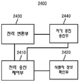
전력 전송 커버리지 제어 장치(2300)는 도 18의 무선 전력 송신기(1801)에 구비될 수 있다. 따라서, 전력 전송 커버리지 제어 장치(2300)는 도 23에 도시된 구성 외에, 도 1 내지 도 7에서 설명된 다양한 구성을 추가로 포함할 수 있고, 또한 도 1 내지 도 7에서 설명된 다양한 동작들을 수행할 수 도 있다. The power
전력 전송 커버리지 제어 장치(2300)는 공진 채널을 통해 메인 디바이스로부터 전력을 공급 받는 복수의 주변 디바이스들을 포함하는 무선 전력 전송 네트워크의 전력 전송 커버리지를 제어한다. The power transmission
전력 전송 커버리지 제어 장치(2300)는 전력 송신 제어부(2310) 및 단절 상태 확인부(2320)를 포함한다. 물론, 전력 전송 커버리지 제어 장치(2300)는 송출 전력을 생성하는 전력 변환부(2330) 및 공진기 및 임피던스 매칭회로를 포함하는 자기 공진 송신부(2340)를 더 포함할 수 있다. The power transmission
전력 변환부(2330) 및 자기 공진 송신부(2340)의 동작은 도 1 내지 도 7, 및 도 13 내지 도 15에서 설명되어 있는 관계로 상세한 설명은 생략한다. The operation of the
전력 송신 제어부(2310)는 메인 디바이스의 송출 전력량을 제어한다. 다시 발해, 전력 송신 제어부(2310)는 전력 변환부(2330)를 제어하여 송출 전력량을 제어할 수 있다. The power
전력 송신 제어부(2310)는 무선 전력 전송 네트워크 단절 순간의 송출 전력량에 기초하여 상기 전력 전송 커버리지를 형성한다. The power
전력 송신 제어부(2310)는 무선 전력 전송 네트워크 단절이 발생한 타겟 디바이스의 이동 빈도 또는 이동 가능 범위를 고려하여 상기 무선 전력 전송 네트워크 단절 순간의 송출 전력량에 기 설정된 전력 마진(margin)을 적용할 수 있다. The power
예를 들어, 로컬 컴퓨팅 환경의 마우스와 같이 이동 가능한 디바이스는 해당 디바이스의 이동 가능 범위를 고려하여 수 미리 와트 정도의 전력 마진을 설정할 수 있다. 다시 말해, 전력 전송 네트워크가 단절된 순간의 PD 값에 전력 마진을 더한 값을 송출 전력량으로 결정할 수 도 있다. For example, a portable device, such as a mouse in a local computing environment, may set a power margin of several watts in advance, taking into account the movable range of the device. In other words, a value obtained by adding the power margin to the P D value at the moment when the power transmission network is disconnected may be determined as the transmitted power amount.
단절 상태 확인부(2320)는 복수의 주변 디바이스들 중 어느 하나의 무선 전력 전송 네트워크 단절(disconnection) 상태를 확인한다. The disconnection
여기서, 복수의 주변 디바이스들은 상기 메인 디바이스의 입출력 장치를 포함할 수 있고, 따라서, 상기 무선 전력 전송 네트워크는 로컬 컴퓨팅 환경을 제공할 수 있다. Herein, a plurality of peripheral devices may include an input / output device of the main device, and thus the wireless power transmission network may provide a local computing environment.
단절 상태 확인부(2320)는 복수의 주변 디바이스들 각각에 대한 식별자 정보를 인식하고, 상기 송출 전력량을 점진적으로 감소시키는 프로시저 수행 중에 상기 복수의 주변 디바이스들 각각에 대한 식별자 정보를 기초로 전력 수신 상태 정보를 주기적으로 피드백 받고, 상기 전력 수신 상태 정보에 기초하여 상기 복수의 주변 디바이스들 중 어느 하나의 무선 전력 전송 네트워크 단절을 확인할 수 있다. The disconnection
이때, 식별자 정보는 주변 디바이스로부터 블루투스 등의 무선 통신을 통해 수신되고, 식별자 정보로부터 디바이스의 타입이 확인될 수 도 있다. 물론, 로컬 컴퓨팅 환경에서 메인 디바이스는 메인 프로세서에 저장된 장치 정보로부터 주변 디바이스들 각각의 타입 정보를 확인할 수 있다. 식별자 정보는 예를 들어 마우스 장치, 키보드, 미디어 플레이어, 스피커, 모니터 등 해당 디바이스의 종류를 나타내는 정보일 수 있다. 또한, 식별자 정보는 장치 고유의 식별을 위한 식별자, 메인 디바이스로부터 부여 받은 식별자일 수 도 있다. 따라서, 식별자 정보는 디바이스의 타입정보를 포함할 수 있고, 무선 전력 전송 네트워크에서만 사용되는 임시 식별자일 수 도 있다. At this time, the identifier information is received from the peripheral device via wireless communication such as Bluetooth, and the type of the device may be confirmed from the identifier information. Of course, in the local computing environment, the main device can check the type information of each of the peripheral devices from the device information stored in the main processor. The identifier information may be, for example, information indicating the type of the device such as a mouse device, a keyboard, a media player, a speaker, and a monitor. The identifier information may be an identifier for device-specific identification, or an identifier given from the main device. Thus, the identifier information may include type information of the device, and may be a temporary identifier used only in the wireless power transmission network.
전력 수신 상태 정보는 근거리 무선 통신 채널을 통해 송수신 될 수 있다. The power reception status information can be transmitted and received via the short-range wireless communication channel.
단절 상태 확인부(2320)는 전력 전송 효율 또는 디바이스 타입 별로 기 설정된 기준 수신 전력량에 기초하여 상기 무선 전력 전송 네트워크 단절 여부를 결정할 수 있다. The disconnection
예를 들어, 디바이스 타입이 1.5mW를 수신하여 충전하여야 하는 경우 1.2mWatt이하로 전력이 수신되면, 무선 전력 전송 네트워크 단절로 판단될 수 있다. 피드백 되는 상태정보는 전력 수신량 자체일 수도 있고, 전력 수신 효율 정보일 수 도 있다. 물론, 임의의 디바이스로부터 피드백 정보가 기 설정된 시간동안 수신되지 않는 경우 단절 상태로 판단될 수 도 있다. For example, if the device type is 1.5 mW and needs to be charged, if the power is received below 1.2 mWatt, it can be determined that the wireless power transmission network is disconnected. The feedback status information may be the power reception amount itself or the power reception efficiency information. Of course, if the feedback information is not received from any device for a predetermined time, it may be judged as a disconnected state.
단절 상태 확인부(2320)는 무선 전력 전송 네트워크 단절이 발생한 타겟 디바이스의 식별자 정보에 기초하여 상기 타겟 디바이스의 이동 가능성을 판단하고, 상기 타겟 다바이스가 이동 가능한 경우 상기 타겟 디바이스의 위치를 고려하여 상기 무선 공진 채널의 지향성을 조정할 수 있다. The disconnection
도 21과 같이 미리 설정된 위치에 해당 디바이스가 위치할 것이라는 가정하에, 공진 채널의 지향성이 조정될 수 있다. 물론, 근거리 통신의 고지향성 안테나를 사용하는 경우, 디바이스의 현재 위치는 매우 정확하게 파악될 수 있다. The directivity of the resonant channel can be adjusted under the assumption that the device will be located at a predetermined position as shown in Fig. Of course, in the case of using a high-directional antenna of short-range communication, the current position of the device can be grasped very accurately.
이때, 송출 전력량을 점진적으로 감소시키는 프로시저는 상기 타겟 다비이스가 이동 가능한 경우 송출 전력량을 증가시킨 후 재 감소시키는 과정을 포함할 수 있다. 따라서, 이동 가능한 디바이스를 사용자가 직접 이동시키면서 송출 전력량을 결정하는 과정을 여러 번 박복 수행하는 응용 예도 가능하다. At this time, the procedure for gradually reducing the amount of power to be transmitted may include a process of increasing the amount of power to be transmitted when the target device is movable, and then reducing the amount of power. Accordingly, it is possible to apply an application in which the process of determining the amount of power to be transmitted while the user moves the movable device directly is repeatedly carried out many times.
또한, 주변 디바이스들에 구비된 무선 전력 수신기의 공진기 타입이 동일하면, 임의의 디바이스를 메인 디바이스로부터 필요한 최대 거리에 위치 시킨 후 송출 전력량을 결정하는 응용 예도 가능하다.
Also, if the resonator types of the wireless power receivers included in the peripheral devices are the same, an application example in which an arbitrary device is located at a necessary maximum distance from the main device and then determines the amount of power to be output is also possible.
도 24는 다른 일 실시예에 따른 무선 전력 전송 네트워크의 전력 전송 커버리지 제어 장치의 구성예를 설명하기 위한 도면이다.24 is a view for explaining an example of the configuration of a power transmission coverage control apparatus of a wireless power transmission network according to another embodiment.
도 24를 참조하면, 전력 전송 커버리지 제어 장치(2400)는 전력 전송 커버리지 제어 장치(2300)와 유사한 구성을 갖는다. 다만, 전력 전송 커버리지 제어 장치(2400)는 전력 전송 커버리지 제어 장치(2300)와 달리 식별자 정보 확인부(2420)를 포함한다. Referring to FIG. 24, the power transmission
식별자 정보 확인부(2420)는 복수의 주변 디바이스들 각각에 대한 식별자 정보를 확인한다. The identifier
전력 송신 제어부(2410)는 식별자 정보에 기초하여 상기 복수의 디바이스들 중 이동 가능한 타겟 디바이스를 확인하고, 타겟 디바이스의 이동 가능 범위를 기초로 상기 전력 전송 커버리지 형성을 위한 송출 전력량 또는 상기 공진 채널의 지향성을 조정하여 상기 전력 전송 커버리지를 형성한다. The power
이때, 타겟 디바이스의 이동 가능 범위에 대한 정보는 디바이스 타입별로 미리 메인 디바이스 또는 전력 전송 커버리지 제어 장치에 저장되어 있을 수 있다. At this time, information on the movable range of the target device may be stored in advance in the main device or the power transmission coverage control device according to the device type.
전력 송신 제어부(2410)는 현재 송출 전력량에 기 설정된 전력 마진(margin)을 적용하여 상기 전력 전송 커버리지를 형성할 수 있다. 이때, 기 설정된 전력 마진은 타겟 디바이스의 이동 가능 범위를 고려하여 미리 설정된 값일 수 있다. The power
전력 송신 제어부(2410)는 메인 디바이스의 송출 전력량을 점진적으로 감소시키는 프로시저를 반복 수행하고, 상기 프로시저를 반복 수행하는 중에 상기 타겟 디바이스의 무선 전력 전송 네트워크 단절 상태를 확인하고, 상기 무선 전력 전송 네트워크 단절 순간들의 송출 전력량에 기초하여 상기 전력 전송 커버리지를 형성할 수 있다. The power
이때, 전력 송신 제어부(2410)는 무선 전력 전송 네트워크 단절 순간들의 송출 전력량 중 최대값을 최종 송출 전력량으로 결정할 수 도 있다. At this time, the power
물론, 전력 송신 제어부(2410)는 무선 전력 전송 네트워크 단절 순간들의 송출 전력량들의 평균 값을 최종 송출 전력량으로 결정할 수 도 있다.
Of course, the power
이상에서 설명된 장치는 하드웨어 구성요소, 소프트웨어 구성요소, 및/또는 하드웨어 구성요소 및 소프트웨어 구성요소의 조합으로 구현될 수 있다. 예를 들어, 실시예들에서 설명된 장치 및 구성요소는, 예를 들어, 프로세서, 콘트롤러, ALU(arithmetic logic unit), 디지털 신호 프로세서(digital signal processor), 마이크로컴퓨터, FPA(field programmable array), PLU(programmable logic unit), 마이크로프로세서, 또는 명령(instruction)을 실행하고 응답할 수 있는 다른 어떠한 장치와 같이, 하나 이상의 범용 컴퓨터 또는 특수 목적 컴퓨터를 이용하여 구현될 수 있다. 처리 장치는 운영 체제(OS) 및 상기 운영 체제 상에서 수행되는 하나 이상의 소프트웨어 애플리케이션을 수행할 수 있다. 또한, 처리 장치는 소프트웨어의 실행에 응답하여, 데이터를 접근, 저장, 조작, 처리 및 생성할 수도 있다. 이해의 편의를 위하여, 처리 장치는 하나가 사용되는 것으로 설명된 경우도 있지만, 해당 기술분야에서 통상의 지식을 가진 자는, 처리 장치가 복수 개의 처리 요소(processing element) 및/또는 복수 유형의 처리 요소를 포함할 수 있음을 알 수 있다. 예를 들어, 처리 장치는 복수 개의 프로세서 또는 하나의 프로세서 및 하나의 콘트롤러를 포함할 수 있다. 또한, 병렬 프로세서(parallel processor)와 같은, 다른 처리 구성(processing configuration)도 가능하다.The apparatus described above may be implemented as a hardware component, a software component, and / or a combination of hardware components and software components. For example, the apparatus and components described in the embodiments may be implemented within a computer system, such as, for example, a processor, a controller, an arithmetic logic unit (ALU), a digital signal processor, a microcomputer, a field programmable array (FPA) A programmable logic unit (PLU), a microprocessor, or any other device capable of executing and responding to instructions. The processing device may execute an operating system (OS) and one or more software applications running on the operating system. The processing device may also access, store, manipulate, process, and generate data in response to execution of the software. For ease of understanding, the processing apparatus may be described as being used singly, but those skilled in the art will recognize that the processing apparatus may have a plurality of processing elements and / As shown in FIG. For example, the processing unit may comprise a plurality of processors or one processor and one controller. Other processing configurations are also possible, such as a parallel processor.
소프트웨어는 컴퓨터 프로그램(computer program), 코드(code), 명령(instruction), 또는 이들 중 하나 이상의 조합을 포함할 수 있으며, 원하는 대로 동작하도록 처리 장치를 구성하거나 독립적으로 또는 결합적으로(collectively) 처리 장치를 명령할 수 있다. 소프트웨어 및/또는 데이터는, 처리 장치에 의하여 해석되거나 처리 장치에 명령 또는 데이터를 제공하기 위하여, 어떤 유형의 기계, 구성요소(component), 물리적 장치, 가상 장치(virtual equipment), 컴퓨터 저장 매체 또는 장치, 또는 전송되는 신호 파(signal wave)에 영구적으로, 또는 일시적으로 구체화(embody)될 수 있다. 소프트웨어는 네트워크로 연결된 컴퓨터 시스템 상에 분산되어서, 분산된 방법으로 저장되거나 실행될 수도 있다. 소프트웨어 및 데이터는 하나 이상의 컴퓨터 판독 가능 기록 매체에 저장될 수 있다.The software may include a computer program, code, instructions, or a combination of one or more of the foregoing, and may be configured to configure the processing device to operate as desired or to process it collectively or collectively Device can be commanded. The software and / or data may be in the form of any type of machine, component, physical device, virtual equipment, computer storage media, or device , Or may be permanently or temporarily embodied in a transmitted signal wave. The software may be distributed over a networked computer system and stored or executed in a distributed manner. The software and data may be stored on one or more computer readable recording media.
실시예에 따른 방법은 다양한 컴퓨터 수단을 통하여 수행될 수 있는 프로그램 명령 형태로 구현되어 컴퓨터 판독 가능 매체에 기록될 수 있다. 상기 컴퓨터 판독 가능 매체는 프로그램 명령, 데이터 파일, 데이터 구조 등을 단독으로 또는 조합하여 포함할 수 있다. 상기 매체에 기록되는 프로그램 명령은 실시예를 위하여 특별히 설계되고 구성된 것들이거나 컴퓨터 소프트웨어 당업자에게 공지되어 사용 가능한 것일 수도 있다. 컴퓨터 판독 가능 기록 매체의 예에는 하드 디스크, 플로피 디스크 및 자기 테이프와 같은 자기 매체(magnetic media), CD-ROM, DVD와 같은 광기록 매체(optical media), 플롭티컬 디스크(floptical disk)와 같은 자기-광 매체(magneto-optical media), 및 롬(ROM), 램(RAM), 플래시 메모리 등과 같은 프로그램 명령을 저장하고 수행하도록 특별히 구성된 하드웨어 장치가 포함된다. 프로그램 명령의 예에는 컴파일러에 의해 만들어지는 것과 같은 기계어 코드뿐만 아니라 인터프리터 등을 사용해서 컴퓨터에 의해서 실행될 수 있는 고급 언어 코드를 포함한다. 상기된 하드웨어 장치는 실시예의 동작을 수행하기 위해 하나 이상의 소프트웨어 모듈로서 작동하도록 구성될 수 있으며, 그 역도 마찬가지이다.The method according to an embodiment may be implemented in the form of a program command that can be executed through various computer means and recorded in a computer-readable medium. The computer-readable medium may include program instructions, data files, data structures, and the like, alone or in combination. The program instructions to be recorded on the medium may be those specially designed and configured for the embodiments or may be available to those skilled in the art of computer software. Examples of computer-readable media include magnetic media such as hard disks, floppy disks and magnetic tape; optical media such as CD-ROMs and DVDs; magnetic media such as floppy disks; Magneto-optical media, and hardware devices specifically configured to store and execute program instructions such as ROM, RAM, flash memory, and the like. Examples of program instructions include machine language code such as those produced by a compiler, as well as high-level language code that can be executed by a computer using an interpreter or the like. The hardware devices described above may be configured to operate as one or more software modules to perform the operations of the embodiments, and vice versa.
이상과 같이 실시예들이 비록 한정된 실시예와 도면에 의해 설명되었으나, 해당 기술분야에서 통상의 지식을 가진 자라면 상기의 기재로부터 다양한 수정 및 변형이 가능하다. 예를 들어, 설명된 기술들이 설명된 방법과 다른 순서로 수행되거나, 및/또는 설명된 시스템, 구조, 장치, 회로 등의 구성요소들이 설명된 방법과 다른 형태로 결합 또는 조합되거나, 다른 구성요소 또는 균등물에 의하여 대치되거나 치환되더라도 적절한 결과가 달성될 수 있다.While the present invention has been particularly shown and described with reference to exemplary embodiments thereof, it is to be understood that the invention is not limited to the disclosed exemplary embodiments. For example, it is to be understood that the techniques described may be performed in a different order than the described methods, and / or that components of the described systems, structures, devices, circuits, Lt; / RTI > or equivalents, even if it is replaced or replaced.
그러므로, 다른 구현들, 다른 실시예들 및 특허청구범위와 균등한 것들도 후술하는 특허청구범위의 범위에 속한다.
Therefore, other implementations, other embodiments, and equivalents to the claims are also within the scope of the following claims.
Claims (23)
상기 메인 디바이스의 송출 전력량을 점진적으로 감소시키는 프로시저에 의해, 상기 복수의 주변 디바이스들 중 어느 하나의 무선 전력 전송 네트워크 단절(disconnection) 상태를 확인하는 단계; 및
상기 무선 전력 전송 네트워크 단절 순간의 송출 전력량에 기초하여 상기 전력 전송 커버리지를 형성하는 단계
를 포함하는 무선 전력 전송 네트워크의 전력 전송 커버리지 제어 방법.A method of controlling power transmission coverage of a wireless power transmission network, the method comprising: a plurality of peripheral devices powered by the main device through a resonant channel within a power transmission coverage of the main device,
Confirming a disconnection state of any one of the plurality of peripheral devices by a procedure of gradually decreasing an amount of power of the main device; And
Forming the power transmission coverage based on the amount of power delivered at the instant of the wireless power transmission network cut-off
Gt; power control < / RTI >
상기 복수의 주변 디바이스들은 상기 메인 디바이스의 입출력 장치를 포함하고, 상기 무선 전력 전송 네트워크는 로컬 컴퓨팅 환경을 제공하는
무선 전력 전송 네트워크의 전력 전송 커버리지 제어 방법.The method according to claim 1,
Wherein the plurality of peripheral devices comprises an input / output device of the main device, the wireless power transmission network providing a local computing environment
A method for controlling power transmission coverage in a wireless power transmission network.
상기 무선 전력 전송 네트워크 단절 상태를 확인하는 단계는,
상기 메인 디바이스가 상기 복수의 주변 디바이스들 각각에 대한 식별자 정보를 인식하는 것;
상기 송출 전력량을 점진적으로 감소시키는 프로시저 수행 중에 상기 복수의 주변 디바이스들 각각에 대한 식별자 정보를 기초로 전력 수신 상태 정보를 주기적으로 피드백 받는 것; 및
상기 전력 수신 상태 정보에 기초하여 상기 복수의 주변 디바이스들 중 어느 하나의 무선 전력 전송 네트워크 단절을 확인하는 것을 포함하는
무선 전력 전송 네트워크의 전력 전송 커버리지 제어 방법.The method according to claim 1,
Wherein the step of verifying the wireless power transmission network disconnection state comprises:
The main device recognizing identifier information for each of the plurality of peripheral devices;
Periodically receiving power reception status information based on identifier information for each of the plurality of peripheral devices during a procedure of gradually decreasing the amount of power to be transmitted; And
And confirming any one of the plurality of peripheral devices' wireless power transmission network disconnection based on the power receiving status information
A method for controlling power transmission coverage in a wireless power transmission network.
상기 무선 전력 전송 네트워크 단절은 전력 전송 효율, 디바이스 타입 별로 기 설정된 기준 수신 전력량, 및 통신 단절 중 적어도 어느 하나에 기초하여 결정되는
무선 전력 전송 네트워크의 전력 전송 커버리지 제어 방법.The method according to claim 1,
The wireless power transmission network disconnection is determined based on at least one of power transmission efficiency, a predetermined reference received power amount for each device type, and a communication disconnection
A method for controlling power transmission coverage in a wireless power transmission network.
상기 전력 전송 커버리지를 형성하는 단계는,
상기 무선 전력 전송 네트워크 단절이 발생한 타겟 디바이스의 식별자 정보를 확인하는 것;
상기 식별자 정보에 기초하여 상기 타겟 디바이스의 이동 빈도 또는 이동 가능 범위를 확인하는 것; 및
상기 이동 빈도 또는 이동 가능 범위를 고려하여 상기 무선 전력 전송 네트워크 단절 순간의 송출 전력량에 기 설정된 전력 마진(margin)을 적용하는 것을 포함하는
무선 전력 전송 네트워크의 전력 전송 커버리지 제어 방법.The method according to claim 1,
Wherein forming the power transmission coverage comprises:
Confirming the identifier information of the target device in which the wireless power transmission network disconnection occurred;
Confirming the movement frequency or movable range of the target device based on the identifier information; And
And applying a preset power margin to the amount of power delivered at the moment of disconnecting the wireless power transmission network in consideration of the movement frequency or the movable range
A method for controlling power transmission coverage in a wireless power transmission network.
상기 무선 전력 전송 네트워크 단절 상태를 확인하는 단계는,
상기 무선 전력 전송 네트워크 단절이 발생한 타겟 디바이스의 식별자 정보에 기초하여 상기 타겟 디바이스의 이동 가능성을 판단하는 것; 및
상기 타겟 다비이스가 이동 가능한 경우 상기 타겟 디바이스의 위치를 고려하여 상기 무선 공진 채널의 지향성을 조정하는 것을 포함하는
무선 전력 전송 네트워크의 전력 전송 커버리지 제어 방법.The method according to claim 1,
Wherein the step of verifying the wireless power transmission network disconnection state comprises:
Determining the mobility of the target device based on the identifier information of the target device in which the wireless power transmission network disconnection occurred; And
And adjusting the directivity of the wireless resonance channel in consideration of the position of the target device when the target device is movable
A method for controlling power transmission coverage in a wireless power transmission network.
상기 무선 전력 전송 네트워크 단절 상태를 확인하는 단계는,
상기 무선 전력 전송 네트워크 단절이 발생한 타겟 디바이스의 식별자 정보에 기초하여 상기 타겟 디바이스의 이동 가능성을 판단하는 것; 및
상기 타겟 다비이스가 이동 가능한 경우, 송출 전력량을 점진적으로 감소시키는 프로시저는 송출 전력량을 증가시킨 후 재 감소시키는 과정을 포함하는
무선 전력 전송 네트워크의 전력 전송 커버리지 제어 방법.The method according to claim 1,
Wherein the step of verifying the wireless power transmission network disconnection state comprises:
Determining the mobility of the target device based on the identifier information of the target device in which the wireless power transmission network disconnection occurred; And
If the target device is movable, the procedure for gradually reducing the amount of power to be transmitted includes increasing the amount of power to be transmitted and re-decreasing the amount of power to be transmitted
A method for controlling power transmission coverage in a wireless power transmission network.
상기 메인 디바이스는 송출 전력량을 점진적으로 감소시키는 프로시저에 의해, 상기 복수의 주변 디바이스들 중 어느 하나의 무선 전력 전송 네트워크 단절(disconnection) 상태를 확인하고, 상기 무선 전력 전송 네트워크 단절 순간의 송출 전력량에 기초하여 상기 전력 전송 커버리지를 형성하되,
상기 전력 전송 커버리지를 형성하는 단계는,
상기 메인 디바이스의 송출 전력량을 점진적으로 감소시키는 프로시저를 반복 수행하는 것;
상기 프로시저를 반복 수행하는 중에 상기 타겟 디바이스의 무선 전력 전송 네트워크 단절 상태를 확인하는 것; 및
상기 무선 전력 전송 네트워크 단절 순간들의 송출 전력량에 기초하여 상기 전력 전송 커버리지를 형성하는 것을 포함하는
무선 전력 전송 네트워크의 전력 전송 커버리지 제어 방법.A method of controlling power transmission coverage of a wireless power transmission network, the method comprising: a plurality of peripheral devices powered by the main device through a resonant channel within a power transmission coverage of the main device,
Wherein the main device checks a disconnection state of any one of the plurality of peripheral devices by a procedure for gradually decreasing the amount of power to be sent out, To form the power transmission coverage,
Wherein forming the power transmission coverage comprises:
Repeating the procedure of gradually decreasing the amount of power delivered from the main device;
Confirming the wireless power transmission network disconnection state of the target device while iteratively performing the procedure; And
And forming the power transmission coverage based on the transmitted power amount of the wireless power transmission network disconnection moments
A method for controlling power transmission coverage in a wireless power transmission network.
상기 메인 디바이스가 상기 복수의 주변 디바이스들 각각에 대한 식별자 정보를 확인하는 단계; 및
상기 식별자 정보에 기초하여 상기 복수의 디바이스들 중 이동 가능한 타겟 디바이스의 이동 가능 범위를 기초로 상기 전력 전송 커버리지 형성을 위한 송출 전력량 또는 상기 공진 채널의 지향성을 조정하여 상기 전력 전송 커버리지를 형성하는 단계
를 포함하는 무선 전력 전송 네트워크의 전력 전송 커버리지 제어 방법.A method of controlling power transmission coverage of a wireless power transmission network, the method comprising: a plurality of peripheral devices powered by the main device through a resonant channel within a power transmission coverage of the main device,
The main device verifying identifier information for each of the plurality of peripheral devices; And
Forming the power transmission coverage by adjusting the amount of transmitted power for forming the power transmission coverage or the directivity of the resonance channel based on the movable range of the movable target device among the plurality of devices based on the identifier information
Gt; power control < / RTI >
상기 전력 전송 커버리지를 형성하는 단계는 현재 송출 전력량에 기 설정된 전력 마진(margin)을 적용하는 것을 포함하는
무선 전력 전송 네트워크의 전력 전송 커버리지 제어 방법.10. The method of claim 9,
Wherein forming the power transmission coverage comprises applying a predetermined power margin to the current amount of power delivered
A method for controlling power transmission coverage in a wireless power transmission network.
상기 전력 전송 커버리지를 형성하는 단계는,
상기 메인 디바이스의 송출 전력량을 점진적으로 감소시키는 프로시저를 반복 수행하는 것;
상기 프로시저를 반복 수행하는 중에 상기 타겟 디바이스의 무선 전력 전송 네트워크 단절 상태를 확인하는 것; 및
상기 무선 전력 전송 네트워크 단절 순간들의 송출 전력량에 기초하여 상기 전력 전송 커버리지를 형성하는 것을 포함하는
무선 전력 전송 네트워크의 전력 전송 커버리지 제어 방법.10. The method of claim 9,
Wherein forming the power transmission coverage comprises:
Repeating the procedure of gradually decreasing the amount of power delivered from the main device;
Confirming the wireless power transmission network disconnection state of the target device while iteratively performing the procedure; And
And forming the power transmission coverage based on the transmitted power amount of the wireless power transmission network disconnection moments
A method for controlling power transmission coverage in a wireless power transmission network.
상기 전력 전송 커버리지를 형성하는 단계는 상기 무선 전력 전송 네트워크 단절 순간들의 송출 전력량 중 최대값을 최종 송출 전력량으로 결정하는 것을 포함하는
무선 전력 전송 네트워크의 전력 전송 커버리지 제어 방법.12. The method of claim 11,
Wherein forming the power transmission coverage comprises determining a maximum value of the delivered power amount of the wireless power transmission network disconnection moments as a final transmitted power amount
A method for controlling power transmission coverage in a wireless power transmission network.
상기 메인 디바이스의 송출 전력량을 제어하고, 상기 송출 전력량을 점진적으로 감소시키는 프로시저를 수행하는 전력 송신 제어부; 및
상기 복수의 주변 디바이스들 중 어느 하나의 무선 전력 전송 네트워크 단절(disconnection) 상태를 확인하는 단절 상태 확인부를 포함하고,
상기 전력 송신 제어부는 상기 무선 전력 전송 네트워크 단절 순간의 송출 전력량에 기초하여 상기 전력 전송 커버리지를 형성하는
를 포함하는 무선 전력 전송 네트워크의 전력 전송 커버리지 제어 장치.1. A power transmission coverage control apparatus of a wireless power transmission network including a plurality of peripheral devices powered by a main device through a resonant channel,
A power transmission control unit for controlling a transmission power amount of the main device and performing a procedure for gradually reducing the transmission power amount; And
And a disconnection state verifying unit for confirming a disconnection state of one of the plurality of peripheral devices,
Wherein the power transmission control unit forms the power transmission coverage based on the amount of transmitted power at the moment of the wireless power transmission network cut-off
And a power control unit for controlling the power of the wireless power transmission network.
상기 복수의 주변 디바이스들은 상기 메인 디바이스의 입출력 장치를 포함하고, 상기 무선 전력 전송 네트워크는 로컬 컴퓨팅 환경을 제공하는
무선 전력 전송 네트워크의 전력 전송 커버리지 제어 장치.14. The method of claim 13,
Wherein the plurality of peripheral devices comprises an input / output device of the main device, the wireless power transmission network providing a local computing environment
A power transmission coverage control device in a wireless power transmission network.
상기 단절 상태 확인부는,
상기 복수의 주변 디바이스들 각각에 대한 식별자 정보를 인식하고, 상기 송출 전력량을 점진적으로 감소시키는 프로시저 수행 중에 상기 복수의 주변 디바이스들 각각에 대한 식별자 정보를 기초로 전력 수신 상태 정보를 주기적으로 피드백 받고, 상기 전력 수신 상태 정보에 기초하여 상기 복수의 주변 디바이스들 중 어느 하나의 무선 전력 전송 네트워크 단절을 확인하는
무선 전력 전송 네트워크의 전력 전송 커버리지 제어 장치.14. The method of claim 13,
The disconnection state checking unit
Recognizing identifier information for each of the plurality of peripheral devices and periodically receiving power reception status information based on identifier information for each of the plurality of peripheral devices during a procedure of gradually decreasing the amount of power to be transmitted , And determining whether any one of the plurality of peripheral devices is disconnected based on the power reception status information
A power transmission coverage control device in a wireless power transmission network.
상기 단절 상태 확인부는 전력 전송 효율, 디바이스 타입 별로 기 설정된 기준 수신 전력량, 및 통신 단절 중 적어도 어느 하나에 기초하여 상기 무선 전력 전송 네트워크 단절 여부를 결정하는
무선 전력 전송 네트워크의 전력 전송 커버리지 제어 장치.14. The method of claim 13,
The disconnect status checking unit determines whether or not the wireless power transmission network is disconnected based on at least one of power transmission efficiency, predetermined reference received power amount for each device type, and communication disconnection
A power transmission coverage control device in a wireless power transmission network.
상기 전력 송신 제어부는,
상기 무선 전력 전송 네트워크 단절이 발생한 타겟 디바이스의 이동 빈도 또는 이동 가능 범위를 고려하여 상기 무선 전력 전송 네트워크 단절 순간의 송출 전력량에 기 설정된 전력 마진(margin)을 적용하는
무선 전력 전송 네트워크의 전력 전송 커버리지 제어 장치.14. The method of claim 13,
Wherein the power transmission control unit comprises:
A predetermined power margin is applied to the amount of power delivered at the moment of disconnecting the wireless power transmission network in consideration of the movement frequency or movable range of the target device in which the wireless power transmission network is disconnected
A power transmission coverage control device in a wireless power transmission network.
상기 단절 상태 확인부는,
상기 무선 전력 전송 네트워크 단절이 발생한 타겟 디바이스의 식별자 정보에 기초하여 상기 타겟 디바이스의 이동 가능성을 판단하고, 상기 타겟 다비이스가 이동 가능한 경우 상기 타겟 디바이스의 위치를 고려하여 상기 무선 공진 채널의 지향성을 조정하는
무선 전력 전송 네트워크의 전력 전송 커버리지 제어 장치.14. The method of claim 13,
The disconnection state checking unit
Determining a possibility of movement of the target device based on the identifier information of the target device in which the wireless power transmission network disconnection has occurred and adjusting the directivity of the wireless resonance channel in consideration of the position of the target device when the target device is movable doing
A power transmission coverage control device in a wireless power transmission network.
상기 단절 상태 확인부는 상기 무선 전력 전송 네트워크 단절이 발생한 타겟 디바이스의 식별자 정보에 기초하여 상기 타겟 디바이스의 이동 가능성을 판단하고,
상기 송출 전력량을 점진적으로 감소시키는 프로시저는 상기 타겟 다비이스가 이동 가능한 경우 송출 전력량을 증가시킨 후 재 감소시키는 과정을 포함하는
무선 전력 전송 네트워크의 전력 전송 커버리지 제어 장치.14. The method of claim 13,
Wherein the disconnection state checking unit determines the possibility of movement of the target device based on the identifier information of the target device in which the wireless power transmission network disconnection occurred,
Wherein the procedure for gradually reducing the amount of power to be transmitted includes increasing the amount of power to be transmitted when the target device is movable and re-decreasing the amount of power to be transmitted
A power transmission coverage control device in a wireless power transmission network.
상기 복수의 주변 디바이스들 각각에 대한 식별자 정보를 확인하는 식별자 정보 확인부; 및
상기 식별자 정보에 기초하여 상기 복수의 디바이스들 중 이동 가능한 타겟 디바이스의 이동 가능 범위를 기초로 상기 전력 전송 커버리지 형성을 위한 송출 전력량 또는 상기 공진 채널의 지향성을 조정하여 상기 전력 전송 커버리지를 형성하는 전력 송신 제어부
를 포함하는 무선 전력 전송 네트워크의 전력 전송 커버리지 제어 장치.1. A power transmission coverage control apparatus of a wireless power transmission network including a plurality of peripheral devices powered by a main device through a resonant channel,
An identifier information verifying unit for verifying the identifier information of each of the plurality of peripheral devices; And
And a controller for controlling the power amount for forming the power transmission coverage or the directivity of the resonant channel based on the movable range of the movable target device among the plurality of devices based on the identifier information, The control unit
And a power control unit for controlling the power of the wireless power transmission network.
상기 전력 송신 제어부는 현재 송출 전력량에 기 설정된 전력 마진(margin)을 적용하여 상기 전력 전송 커버리지를 형성하는
무선 전력 전송 네트워크의 전력 전송 커버리지 제어 장치.21. The method of claim 20,
The power transmission control unit applies the predetermined power margin to the current amount of transmitted power to form the power transmission coverage
A power transmission coverage control device in a wireless power transmission network.
상기 전력 송신 제어부는,
상기 메인 디바이스의 송출 전력량을 점진적으로 감소시키는 프로시저를 반복 수행하고, 상기 프로시저를 반복 수행하는 중에 상기 타겟 디바이스의 무선 전력 전송 네트워크 단절 상태를 확인하고, 상기 무선 전력 전송 네트워크 단절 순간들의 송출 전력량에 기초하여 상기 전력 전송 커버리지를 형성하는
무선 전력 전송 네트워크의 전력 전송 커버리지 제어 장치.21. The method of claim 20,
Wherein the power transmission control unit comprises:
A step of repeatedly performing a procedure of gradually reducing the amount of power delivered by the main device, confirming a wireless power transmission network disconnection state of the target device while iteratively performing the procedure, Lt; RTI ID = 0.0 >
A power transmission coverage control device in a wireless power transmission network.
상기 전력 송신 제어부는 상기 무선 전력 전송 네트워크 단절 순간들의 송출 전력량 중 최대값을 최종 송출 전력량으로 결정하는
무선 전력 전송 네트워크의 전력 전송 커버리지 제어 장치.
21. The method of claim 20,
The power transmission control unit determines the maximum value of the transmitted power amount of the wireless power transmission network disconnecting moments as the final transmitted power amount
A power transmission coverage control device in a wireless power transmission network.
Priority Applications (5)
| Application Number | Priority Date | Filing Date | Title |
|---|---|---|---|
| US15/535,400 US11381121B2 (en) | 2014-11-03 | 2015-11-10 | Apparatus and method for controlling power transmission coverage of wireless power transmission network |
| PCT/KR2015/012035 WO2016099032A1 (en) | 2014-12-16 | 2015-11-10 | Apparatus and method for controlling power transmission coverage of wireless power transmission network |
| KR1020210125899A KR102462741B1 (en) | 2014-11-03 | 2021-09-23 | Method and apparutus for controlling a power transmission coverage of wireless power transmission network |
| US17/809,603 US11936194B2 (en) | 2014-12-16 | 2022-06-29 | Apparatus and method for controlling power transmission coverage of wireless power transmission network |
| US18/428,437 US20240195219A1 (en) | 2014-12-16 | 2024-01-31 | Apparatus and method for controlling power transmission coverage of wireless power transmission network |
Applications Claiming Priority (2)
| Application Number | Priority Date | Filing Date | Title |
|---|---|---|---|
| KR20140151175 | 2014-11-03 | ||
| KR1020140151175 | 2014-11-03 |
Related Child Applications (1)
| Application Number | Title | Priority Date | Filing Date |
|---|---|---|---|
| KR1020210125899A Division KR102462741B1 (en) | 2014-11-03 | 2021-09-23 | Method and apparutus for controlling a power transmission coverage of wireless power transmission network |
Publications (1)
| Publication Number | Publication Date |
|---|---|
| KR20160051497A true KR20160051497A (en) | 2016-05-11 |
Family
ID=56026229
Family Applications (13)
| Application Number | Title | Priority Date | Filing Date |
|---|---|---|---|
| KR1020140181585A KR20160051497A (en) | 2014-11-03 | 2014-12-16 | Method and apparutus for controlling a power transmission coverage of wireless power transmission network |
| KR1020140184408A KR102322891B1 (en) | 2014-11-03 | 2014-12-19 | Power control method and apparatus in wireless power transmission system |
| KR1020140191656A KR102316575B1 (en) | 2014-11-03 | 2014-12-29 | Wireless power transmission and charging system |
| KR1020140191657A KR20160051502A (en) | 2014-11-03 | 2014-12-29 | Wireless power transmission and charging system |
| KR1020210112998A KR102609937B1 (en) | 2014-11-03 | 2021-08-26 | Wireless power transmission and charging system |
| KR1020210125899A KR102462741B1 (en) | 2014-11-03 | 2021-09-23 | Method and apparutus for controlling a power transmission coverage of wireless power transmission network |
| KR1020210138364A KR102550054B1 (en) | 2014-11-03 | 2021-10-18 | Wireless power transmission and charging system |
| KR1020210148176A KR102473737B1 (en) | 2014-11-03 | 2021-11-01 | Power control method and apparatus in wireless power transmission system |
| KR1020220163334A KR102609567B1 (en) | 2014-11-03 | 2022-11-29 | Power control method and apparatus in wireless power transmission system |
| KR1020230082624A KR102679964B1 (en) | 2014-11-03 | 2023-06-27 | Wireless power transmission and charging system |
| KR1020230168043A KR20230169014A (en) | 2014-11-03 | 2023-11-28 | Wireless power transmission and charging system |
| KR1020230169794A KR20230169023A (en) | 2014-11-03 | 2023-11-29 | Power control method and apparatus in wireless power transmission system |
| KR1020240083102A KR20240108343A (en) | 2014-11-03 | 2024-06-25 | Wireless power transmission and charging system |
Family Applications After (12)
| Application Number | Title | Priority Date | Filing Date |
|---|---|---|---|
| KR1020140184408A KR102322891B1 (en) | 2014-11-03 | 2014-12-19 | Power control method and apparatus in wireless power transmission system |
| KR1020140191656A KR102316575B1 (en) | 2014-11-03 | 2014-12-29 | Wireless power transmission and charging system |
| KR1020140191657A KR20160051502A (en) | 2014-11-03 | 2014-12-29 | Wireless power transmission and charging system |
| KR1020210112998A KR102609937B1 (en) | 2014-11-03 | 2021-08-26 | Wireless power transmission and charging system |
| KR1020210125899A KR102462741B1 (en) | 2014-11-03 | 2021-09-23 | Method and apparutus for controlling a power transmission coverage of wireless power transmission network |
| KR1020210138364A KR102550054B1 (en) | 2014-11-03 | 2021-10-18 | Wireless power transmission and charging system |
| KR1020210148176A KR102473737B1 (en) | 2014-11-03 | 2021-11-01 | Power control method and apparatus in wireless power transmission system |
| KR1020220163334A KR102609567B1 (en) | 2014-11-03 | 2022-11-29 | Power control method and apparatus in wireless power transmission system |
| KR1020230082624A KR102679964B1 (en) | 2014-11-03 | 2023-06-27 | Wireless power transmission and charging system |
| KR1020230168043A KR20230169014A (en) | 2014-11-03 | 2023-11-28 | Wireless power transmission and charging system |
| KR1020230169794A KR20230169023A (en) | 2014-11-03 | 2023-11-29 | Power control method and apparatus in wireless power transmission system |
| KR1020240083102A KR20240108343A (en) | 2014-11-03 | 2024-06-25 | Wireless power transmission and charging system |
Country Status (2)
| Country | Link |
|---|---|
| US (2) | US20180138758A1 (en) |
| KR (13) | KR20160051497A (en) |
Cited By (3)
| Publication number | Priority date | Publication date | Assignee | Title |
|---|---|---|---|---|
| EP3467997A4 (en) * | 2016-05-31 | 2020-01-01 | LG Innotek Co., Ltd. | Wireless power transmission method and device therefor |
| WO2022015080A1 (en) * | 2020-07-15 | 2022-01-20 | 엘지전자 주식회사 | Wireless power transmitter and wireless power transmission method by wireless power transmitter |
| US11533093B2 (en) | 2019-04-18 | 2022-12-20 | Industry-Academic Cooperation Foundation, Yonsei University | Apparatus and method for transmitting and receiving information and power in wireless communication system |
Families Citing this family (34)
| Publication number | Priority date | Publication date | Assignee | Title |
|---|---|---|---|---|
| US9806537B2 (en) * | 2011-12-15 | 2017-10-31 | Samsung Electronics Co., Ltd | Apparatus and method for determining whether a power receiver is removed from the apparatus |
| WO2016099032A1 (en) | 2014-12-16 | 2016-06-23 | 주식회사 한림포스텍 | Apparatus and method for controlling power transmission coverage of wireless power transmission network |
| KR20160051497A (en) | 2014-11-03 | 2016-05-11 | 주식회사 한림포스텍 | Method and apparutus for controlling a power transmission coverage of wireless power transmission network |
| WO2017018800A1 (en) | 2015-07-27 | 2017-02-02 | Samsung Electronics Co., Ltd. | Method for transmitting wireless power in wireless charging system including a wireless power transmitting unit and wireless power receiving unit |
| US20170104357A1 (en) * | 2015-10-07 | 2017-04-13 | Intel Corporation | Dominant power receiving unit selection |
| US10971952B2 (en) * | 2016-01-21 | 2021-04-06 | Maxell, Ltd. | Wireless power transfer device |
| US10530196B2 (en) * | 2016-02-05 | 2020-01-07 | Texas Instruments Incorporated | Methods and apparatus for power loss calibration in a wireless power system |
| DE102017002146A1 (en) | 2016-03-04 | 2017-09-07 | Logitech Europe S.A. | Wireless charging for an input device |
| US20170256978A1 (en) * | 2016-03-04 | 2017-09-07 | Logitech Europe S.A. | Wireless charging for an input device |
| KR102572577B1 (en) * | 2016-04-15 | 2023-08-30 | 삼성전자주식회사 | Charging apparatus and method for controlling wireless charging |
| KR20170140734A (en) * | 2016-06-13 | 2017-12-21 | 엘지이노텍 주식회사 | Foreign Object Detection Method and Apparatus and System therefor |
| JP7164934B2 (en) * | 2016-10-05 | 2022-11-02 | ラピスセミコンダクタ株式会社 | Power transmission device and power transmission method |
| WO2018066789A1 (en) * | 2016-10-07 | 2018-04-12 | 엘지전자 주식회사 | Coil structure of wireless power transmitter |
| KR20180123891A (en) * | 2017-05-10 | 2018-11-20 | 엘지이노텍 주식회사 | Wireless Charging Method and Apparatus and System therefor |
| KR20190083454A (en) * | 2018-01-04 | 2019-07-12 | 엘지이노텍 주식회사 | Wireless charging device and wireless charging method |
| KR102046324B1 (en) * | 2018-03-19 | 2019-11-19 | 세종대학교산학협력단 | Method for receiving signal and user terminal for executing the same |
| EP3547487B1 (en) * | 2018-03-29 | 2020-03-25 | NOK9 ip AB | A testing device for testing a wireless power transmitter device, and an associated method |
| US20210028653A1 (en) * | 2018-04-05 | 2021-01-28 | Lg Electronics Inc. | Device and method for controlling transmission of power in wireless power transmitting system |
| EP3776791A1 (en) * | 2018-04-06 | 2021-02-17 | ABB Schweiz AG | A power transfer system for electric vehicles and a control method thereof |
| CN111937267A (en) * | 2018-04-06 | 2020-11-13 | Abb瑞士股份有限公司 | Power transmission system for electric vehicle and control method thereof |
| PL3784517T3 (en) | 2018-04-23 | 2023-06-26 | ABB E-mobility B.V. | A power transfer system for electric vehicles and a control method thereof |
| JP7115927B2 (en) * | 2018-07-24 | 2022-08-09 | 株式会社ダイヘン | Power transmission device, control method and computer program |
| JP7137989B2 (en) * | 2018-07-24 | 2022-09-15 | 株式会社ダイヘン | transmission equipment |
| US10658878B2 (en) * | 2018-08-31 | 2020-05-19 | Apple Inc. | Wireless charging system with temperature sensor array |
| US10505403B1 (en) * | 2018-08-31 | 2019-12-10 | Apple Inc. | Wireless charging system with temperature sensing |
| US11177678B2 (en) * | 2018-11-16 | 2021-11-16 | Korea Advanced Institute Of Science And Technology | Wireless power transmission method and device in which rectifier performance of IOT sensor is taken into consideration |
| KR102148082B1 (en) * | 2018-11-29 | 2020-08-26 | 한국과학기술원 | Determination method of the magnetic resonant condition for the milti-device wireless power transfer systems |
| WO2020153578A1 (en) * | 2019-01-23 | 2020-07-30 | 엘지전자 주식회사 | Method and apparatus for performing wireless power transmission on basis of authentication |
| CN112217291A (en) * | 2019-07-11 | 2021-01-12 | 泰科电子(上海)有限公司 | Sensing device and electromagnetic device system comprising same |
| CN114503695A (en) * | 2019-08-06 | 2022-05-13 | 诺基亚通信公司 | Method for controlling radio frequency transmission |
| US11457483B2 (en) * | 2020-03-30 | 2022-09-27 | Citrix Systems, Inc. | Managing connections between a user device and peripheral devices |
| CN113315256B (en) * | 2021-05-25 | 2024-08-20 | 南京大学 | Remote multi-device wireless charging plane |
| CN115384330A (en) * | 2022-07-21 | 2022-11-25 | 广西电网有限责任公司电力科学研究院 | Double-parking-space wireless charging pile and control method thereof |
| US11949256B1 (en) * | 2022-10-18 | 2024-04-02 | Hewlett-Packard Development Company, L.P. | Wireless polling frequency alteration |
Family Cites Families (65)
| Publication number | Priority date | Publication date | Assignee | Title |
|---|---|---|---|---|
| EP1751834B1 (en) * | 2004-05-11 | 2009-12-02 | Access Business Group International LLC | Controlling inductive power transfer systems |
| JP4519142B2 (en) | 2005-01-13 | 2010-08-04 | 富士通株式会社 | Information access system and method for accessing information in a contactless information storage device |
| JP2010503368A (en) * | 2006-09-01 | 2010-01-28 | パワーキャスト コーポレイション | Hybrid power extraction and method |
| TW200952303A (en) * | 2008-06-13 | 2009-12-16 | Kye Systems Corp | Auto-rechargeable wireless computer peripheral device |
| US8947042B2 (en) | 2008-11-13 | 2015-02-03 | Qualcomm Incorporated | Wireless power and data transfer for electronic devices |
| KR100971705B1 (en) * | 2009-09-03 | 2010-07-22 | 주식회사 한림포스텍 | Non-contact charging system |
| US8497658B2 (en) | 2009-01-22 | 2013-07-30 | Qualcomm Incorporated | Adaptive power control for wireless charging of devices |
| US9312924B2 (en) | 2009-02-10 | 2016-04-12 | Qualcomm Incorporated | Systems and methods relating to multi-dimensional wireless charging |
| CN102334258B (en) | 2009-02-27 | 2015-08-05 | 皇家飞利浦电子股份有限公司 | The wirelessly method of transmission power, conveying equipment and transport control system |
| US8803474B2 (en) * | 2009-03-25 | 2014-08-12 | Qualcomm Incorporated | Optimization of wireless power devices |
| US8970180B2 (en) | 2009-04-07 | 2015-03-03 | Qualcomm Incorporated | Wireless power transmission scheduling |
| EP2417686A1 (en) * | 2009-04-08 | 2012-02-15 | Access Business Group International LLC | Selectable coil array |
| US9086864B2 (en) | 2009-11-17 | 2015-07-21 | Apple Inc. | Wireless power utilization in a local computing environment |
| WO2011063108A2 (en) | 2009-11-19 | 2011-05-26 | Access Business Group International Llc | Multiple use wireless power systems |
| EP2367263B1 (en) * | 2010-03-19 | 2019-05-01 | TDK Corporation | Wireless power feeder, wireless power receiver, and wireless power transmission system |
| JP5810291B2 (en) | 2010-03-30 | 2015-11-11 | パナソニックIpマネジメント株式会社 | Wireless power transmission system |
| US8860364B2 (en) | 2010-04-23 | 2014-10-14 | Qualcomm Incorporated | Wireless power distribution among a plurality of receivers |
| KR20180004296A (en) | 2010-11-23 | 2018-01-10 | 애플 인크. | Wireless power utilization in a local computing environment |
| JP5592242B2 (en) | 2010-12-03 | 2014-09-17 | 富士通テン株式会社 | Power receiving device, power transmitting device, and wireless power transmission system |
| JP5564412B2 (en) * | 2010-12-10 | 2014-07-30 | 株式会社日立製作所 | Wireless power transmission system, power transmission device, and power reception device |
| US9006935B2 (en) * | 2011-03-30 | 2015-04-14 | Tdk Corporation | Wireless power feeder/receiver and wireless power transmission system |
| AU2011369465B2 (en) | 2011-05-31 | 2015-04-09 | Apple Inc. | Magnetically de-coupled multiple resonating coils in a tightly spaced array |
| US9306401B2 (en) * | 2011-06-29 | 2016-04-05 | Lg Electronics Inc. | Wireless power transmitter and wireless power transfer method thereof in many-to-one communication |
| WO2013035188A1 (en) | 2011-09-08 | 2013-03-14 | 富士通株式会社 | Transmitting device, receiving device, and non-contact charging method |
| KR20130028446A (en) * | 2011-09-09 | 2013-03-19 | 엘지이노텍 주식회사 | A wireless power transmission apparatus and method thereof |
| KR20130033867A (en) | 2011-09-27 | 2013-04-04 | 삼성전기주식회사 | Wireless power transmission system |
| KR101338732B1 (en) * | 2011-11-10 | 2013-12-06 | 엘지이노텍 주식회사 | Apparatus for transmmiting wireless power and apparatus for receiving wireless power and method for transmitting wireless power, method for receiving wireless power, method for transmitting information and method for receiving information |
| US9118203B2 (en) * | 2011-11-15 | 2015-08-25 | Qualcomm Incorporated | Systems and methods for induction charging with a closed magnetic loop |
| KR101305823B1 (en) * | 2011-11-25 | 2013-09-06 | 한국전기연구원 | Apparatus for relaying wireless power, method for transmitting wireless power and method for contorlling resonance frequency |
| KR101829257B1 (en) | 2011-11-29 | 2018-03-30 | 삼성전자주식회사 | Wireless power transmission system based on cell division |
| KR101848931B1 (en) * | 2011-12-15 | 2018-04-16 | 삼성전자주식회사 | Wireless power charge device and method |
| US9331520B2 (en) | 2011-12-22 | 2016-05-03 | Texas Instruments Incorporated | Inductively coupled charger |
| CN104067477B (en) | 2012-01-24 | 2018-02-23 | 捷通国际有限公司 | Wireless power control system |
| US9018898B2 (en) * | 2012-02-10 | 2015-04-28 | Sandisk Technologies Inc. | Regulation of wirelessly charging multiple devices from the same source |
| KR101371782B1 (en) | 2012-03-05 | 2014-03-07 | 엘지이노텍 주식회사 | Apparatus for receiving wireless power and system for transmitting wireless power and method for delivering wireless power |
| US9531441B2 (en) * | 2012-02-21 | 2016-12-27 | Lg Innotek Co., Ltd. | Wireless power receiver and method of managing power thereof |
| KR20130098546A (en) * | 2012-02-28 | 2013-09-05 | 삼성전자주식회사 | Method and devices for transmitting signal from a plurality of wireless power receivers to wireless power provider |
| JP6337308B2 (en) * | 2012-05-20 | 2018-06-06 | フィリップス アイピー ベンチャーズ ビー ヴィ | System and method for communicating in a wireless power system |
| CN102650064A (en) | 2012-05-23 | 2012-08-29 | 深圳市新星轻合金材料股份有限公司 | Potassium cryolite used for aluminum electrolysis industry and preparation method for potassium cryolite |
| EP3185262B1 (en) | 2012-07-09 | 2018-09-12 | Lg Electronics Inc. | Wireless power transfer method, apparatus and system |
| KR102099819B1 (en) | 2012-07-09 | 2020-04-10 | 엘지전자 주식회사 | Wireless power transfer method, apparatus and system |
| KR101848303B1 (en) * | 2012-07-10 | 2018-04-13 | 삼성전자주식회사 | Method for controlling power trasnmitting of wireless power transmitter and the wireless power transmitter thereof |
| KR101962667B1 (en) * | 2012-07-12 | 2019-03-27 | 삼성전자주식회사 | Wireless power transmitter, wireless power receiver and method for controlling each thereof |
| KR101956570B1 (en) | 2012-09-05 | 2019-03-11 | 엘지전자 주식회사 | Wireless power receiver supporting both inductive and resonant method and wireless power receiving method |
| US9276440B2 (en) * | 2012-09-07 | 2016-03-01 | WIPQTUS Inc. | Multi-mode multi-coupling multi-protocol ubiquitous wireless power transmitter |
| KR101601352B1 (en) * | 2012-09-26 | 2016-03-08 | 엘지이노텍 주식회사 | Apparatus for transmitting wireless power and method for controlling power thereof |
| KR101965252B1 (en) | 2012-12-14 | 2019-04-04 | 삼성전자 주식회사 | Wireless power transmission device, wireless power reception device, wireless power transmission system and wireless power transmission method |
| KR102044807B1 (en) | 2013-03-18 | 2019-11-15 | 삼성전자주식회사 | Wireless power transmission control apparatus and wireless power transmission control method |
| KR20140121200A (en) * | 2013-04-05 | 2014-10-15 | 엘지전자 주식회사 | Wireless power receiving apparatus and wireless power transmitting/receiving apparatus |
| KR101542481B1 (en) | 2013-04-17 | 2015-08-06 | 서울대학교산학협력단 | System and Method for Wireless Power Charging, and Wireless Power Transfer |
| KR102055866B1 (en) | 2013-05-03 | 2019-12-13 | 삼성전자주식회사 | Wireless power transmitter, wireless power receiver and method for controlling each thereof |
| KR20150000028A (en) * | 2013-06-20 | 2015-01-02 | 삼성전자주식회사 | Wireless power transfer system with ability to detect charging circumstances |
| KR101851026B1 (en) | 2013-09-25 | 2018-04-20 | 삼성전자주식회사 | Wireless power charge device and method |
| US10454303B2 (en) * | 2013-11-20 | 2019-10-22 | Wits Co., Ltd. | Non-contact power supply device and non-contact power supply method |
| TWI528802B (en) * | 2013-12-27 | 2016-04-01 | 瑞軒科技股份有限公司 | Method and system for controlling television |
| KR101835125B1 (en) | 2014-03-21 | 2018-03-08 | 엘지이노텍 주식회사 | Apparatus for receiving wireless power and method for controlling power thereof |
| KR101806592B1 (en) | 2014-04-09 | 2017-12-07 | 엘지이노텍 주식회사 | Apparatus for transmitting wireless power and method for transmitting wireless power |
| US11103715B2 (en) | 2014-06-27 | 2021-08-31 | Cochlear Limited | Devices and methods for charging medical devices |
| GB2534114A (en) * | 2014-09-30 | 2016-07-20 | Drayson Tech (Europe) Ltd | Inductive power transfer system |
| KR20160051497A (en) | 2014-11-03 | 2016-05-11 | 주식회사 한림포스텍 | Method and apparutus for controlling a power transmission coverage of wireless power transmission network |
| WO2016072707A1 (en) | 2014-11-03 | 2016-05-12 | 주식회사 한림포스텍 | Wireless power transmission and charging system |
| WO2016099032A1 (en) | 2014-12-16 | 2016-06-23 | 주식회사 한림포스텍 | Apparatus and method for controlling power transmission coverage of wireless power transmission network |
| WO2016072709A1 (en) | 2014-11-03 | 2016-05-12 | 주식회사 한림포스텍 | Wireless power transmission and charging system |
| WO2016072706A1 (en) | 2014-11-03 | 2016-05-12 | 주식회사 한림포스텍 | Method and apparatus for controlling power in wireless power transfer system |
| JP2024044859A (en) * | 2022-09-21 | 2024-04-02 | キヤノン株式会社 | Power transmission device, control method of power transmission device, and program |
-
2014
- 2014-12-16 KR KR1020140181585A patent/KR20160051497A/en active Application Filing
- 2014-12-19 KR KR1020140184408A patent/KR102322891B1/en active IP Right Grant
- 2014-12-29 KR KR1020140191656A patent/KR102316575B1/en active IP Right Grant
- 2014-12-29 KR KR1020140191657A patent/KR20160051502A/en active Application Filing
-
2015
- 2015-11-03 US US15/522,773 patent/US20180138758A1/en active Pending
- 2015-11-10 US US15/535,400 patent/US11381121B2/en active Active
-
2021
- 2021-08-26 KR KR1020210112998A patent/KR102609937B1/en active IP Right Grant
- 2021-09-23 KR KR1020210125899A patent/KR102462741B1/en active IP Right Grant
- 2021-10-18 KR KR1020210138364A patent/KR102550054B1/en active IP Right Grant
- 2021-11-01 KR KR1020210148176A patent/KR102473737B1/en active IP Right Grant
-
2022
- 2022-11-29 KR KR1020220163334A patent/KR102609567B1/en active IP Right Grant
-
2023
- 2023-06-27 KR KR1020230082624A patent/KR102679964B1/en active IP Right Grant
- 2023-11-28 KR KR1020230168043A patent/KR20230169014A/en active Application Filing
- 2023-11-29 KR KR1020230169794A patent/KR20230169023A/en active Application Filing
-
2024
- 2024-06-25 KR KR1020240083102A patent/KR20240108343A/en active Search and Examination
Cited By (3)
| Publication number | Priority date | Publication date | Assignee | Title |
|---|---|---|---|---|
| EP3467997A4 (en) * | 2016-05-31 | 2020-01-01 | LG Innotek Co., Ltd. | Wireless power transmission method and device therefor |
| US11533093B2 (en) | 2019-04-18 | 2022-12-20 | Industry-Academic Cooperation Foundation, Yonsei University | Apparatus and method for transmitting and receiving information and power in wireless communication system |
| WO2022015080A1 (en) * | 2020-07-15 | 2022-01-20 | 엘지전자 주식회사 | Wireless power transmitter and wireless power transmission method by wireless power transmitter |
Also Published As
| Publication number | Publication date |
|---|---|
| KR20210119360A (en) | 2021-10-05 |
| KR20230104557A (en) | 2023-07-10 |
| KR102679964B1 (en) | 2024-07-01 |
| KR102550054B1 (en) | 2023-06-30 |
| KR102316575B1 (en) | 2021-10-26 |
| KR20210129621A (en) | 2021-10-28 |
| KR102609937B1 (en) | 2023-12-05 |
| US11381121B2 (en) | 2022-07-05 |
| KR20230169023A (en) | 2023-12-15 |
| KR20220165698A (en) | 2022-12-15 |
| KR20230169014A (en) | 2023-12-15 |
| US20180138758A1 (en) | 2018-05-17 |
| KR102322891B1 (en) | 2021-11-11 |
| KR20210134565A (en) | 2021-11-10 |
| KR20220150867A (en) | 2022-11-11 |
| KR20160051501A (en) | 2016-05-11 |
| KR102462741B1 (en) | 2022-11-03 |
| KR20160051502A (en) | 2016-05-11 |
| KR20240108343A (en) | 2024-07-09 |
| KR102473737B1 (en) | 2022-12-02 |
| KR20160051498A (en) | 2016-05-11 |
| KR102609567B1 (en) | 2023-12-04 |
| KR20210108347A (en) | 2021-09-02 |
| US20170338685A1 (en) | 2017-11-23 |
Similar Documents
| Publication | Publication Date | Title |
|---|---|---|
| KR102462741B1 (en) | Method and apparutus for controlling a power transmission coverage of wireless power transmission network | |
| KR102649669B1 (en) | Wireless power transmission and charging system | |
| KR20150098575A (en) | Method for controlling wireless power transmitter and wireless power transmitter | |
| KR20150098589A (en) | Method for preventing abnormal situation in wireless charge | |
| KR20150010460A (en) | Method for adjusting a voltage setting value for wireless charge in wireless power network | |
| KR20150098222A (en) | Method for detecting a load in wireless charge | |
| US11936194B2 (en) | Apparatus and method for controlling power transmission coverage of wireless power transmission network | |
| KR102544408B1 (en) | Wireless power transmission and charging system | |
| KR20170035213A (en) | Wireless power transmitter and method for controlling the same | |
| KR102713330B1 (en) | Method and apparutus for controlling a power transmission coverage of wireless power transmission network | |
| KR20240145451A (en) | Method and apparatus for controlling a power transmission coverage of wireless power transmission network | |
| KR20170013142A (en) | Method for transmitting a wireless power in wireless charge system, the wireless power transmitting unit, the wireless power receiving unit |
Legal Events
| Date | Code | Title | Description |
|---|---|---|---|
| A201 | Request for examination | ||
| E902 | Notification of reason for refusal | ||
| E601 | Decision to refuse application | ||
| A107 | Divisional application of patent |