KR20160039212A - Suppression of spurious harmonics generated in tx driver amplifiers - Google Patents
Suppression of spurious harmonics generated in tx driver amplifiers Download PDFInfo
- Publication number
- KR20160039212A KR20160039212A KR1020167003979A KR20167003979A KR20160039212A KR 20160039212 A KR20160039212 A KR 20160039212A KR 1020167003979 A KR1020167003979 A KR 1020167003979A KR 20167003979 A KR20167003979 A KR 20167003979A KR 20160039212 A KR20160039212 A KR 20160039212A
- Authority
- KR
- South Korea
- Prior art keywords
- signal
- phases
- signals
- communication device
- sets
- Prior art date
Links
- 230000001629 suppression Effects 0.000 title description 2
- 238000004891 communication Methods 0.000 claims abstract description 87
- 230000005540 biological transmission Effects 0.000 claims abstract description 29
- 238000000034 method Methods 0.000 claims description 84
- 230000000295 complement effect Effects 0.000 claims description 23
- 238000001914 filtration Methods 0.000 claims 8
- 230000003321 amplification Effects 0.000 claims 4
- 238000003199 nucleic acid amplification method Methods 0.000 claims 4
- 238000006243 chemical reaction Methods 0.000 description 17
- 238000010586 diagram Methods 0.000 description 11
- RDYMFSUJUZBWLH-UHFFFAOYSA-N endosulfan Chemical compound C12COS(=O)OCC2C2(Cl)C(Cl)=C(Cl)C1(Cl)C2(Cl)Cl RDYMFSUJUZBWLH-UHFFFAOYSA-N 0.000 description 4
- 230000001413 cellular effect Effects 0.000 description 2
- 230000007774 longterm Effects 0.000 description 2
- 238000007792 addition Methods 0.000 description 1
- 230000002776 aggregation Effects 0.000 description 1
- 238000004220 aggregation Methods 0.000 description 1
- 239000002131 composite material Substances 0.000 description 1
- 239000012084 conversion product Substances 0.000 description 1
- 238000013461 design Methods 0.000 description 1
- 238000012986 modification Methods 0.000 description 1
- 230000004048 modification Effects 0.000 description 1
- 230000008054 signal transmission Effects 0.000 description 1
- 230000003595 spectral effect Effects 0.000 description 1
- 238000012546 transfer Methods 0.000 description 1
Images


Classifications
-
- H—ELECTRICITY
- H04—ELECTRIC COMMUNICATION TECHNIQUE
- H04B—TRANSMISSION
- H04B1/00—Details of transmission systems, not covered by a single one of groups H04B3/00 - H04B13/00; Details of transmission systems not characterised by the medium used for transmission
- H04B1/02—Transmitters
- H04B1/04—Circuits
- H04B1/0483—Transmitters with multiple parallel paths
-
- H—ELECTRICITY
- H03—ELECTRONIC CIRCUITRY
- H03D—DEMODULATION OR TRANSFERENCE OF MODULATION FROM ONE CARRIER TO ANOTHER
- H03D7/00—Transference of modulation from one carrier to another, e.g. frequency-changing
- H03D7/16—Multiple-frequency-changing
- H03D7/165—Multiple-frequency-changing at least two frequency changers being located in different paths, e.g. in two paths with carriers in quadrature
-
- H—ELECTRICITY
- H03—ELECTRONIC CIRCUITRY
- H03F—AMPLIFIERS
- H03F1/00—Details of amplifiers with only discharge tubes, only semiconductor devices or only unspecified devices as amplifying elements
- H03F1/32—Modifications of amplifiers to reduce non-linear distortion
-
- H—ELECTRICITY
- H03—ELECTRONIC CIRCUITRY
- H03F—AMPLIFIERS
- H03F3/00—Amplifiers with only discharge tubes or only semiconductor devices as amplifying elements
- H03F3/189—High frequency amplifiers, e.g. radio frequency amplifiers
-
- H—ELECTRICITY
- H03—ELECTRONIC CIRCUITRY
- H03F—AMPLIFIERS
- H03F3/00—Amplifiers with only discharge tubes or only semiconductor devices as amplifying elements
- H03F3/20—Power amplifiers, e.g. Class B amplifiers, Class C amplifiers
- H03F3/24—Power amplifiers, e.g. Class B amplifiers, Class C amplifiers of transmitter output stages
-
- H—ELECTRICITY
- H03—ELECTRONIC CIRCUITRY
- H03F—AMPLIFIERS
- H03F3/00—Amplifiers with only discharge tubes or only semiconductor devices as amplifying elements
- H03F3/60—Amplifiers in which coupling networks have distributed constants, e.g. with waveguide resonators
- H03F3/602—Combinations of several amplifiers
-
- H—ELECTRICITY
- H03—ELECTRONIC CIRCUITRY
- H03D—DEMODULATION OR TRANSFERENCE OF MODULATION FROM ONE CARRIER TO ANOTHER
- H03D2200/00—Indexing scheme relating to details of demodulation or transference of modulation from one carrier to another covered by H03D
- H03D2200/0041—Functional aspects of demodulators
- H03D2200/0086—Reduction or prevention of harmonic frequencies
-
- H—ELECTRICITY
- H03—ELECTRONIC CIRCUITRY
- H03F—AMPLIFIERS
- H03F2200/00—Indexing scheme relating to amplifiers
- H03F2200/165—A filter circuit coupled to the input of an amplifier
-
- H—ELECTRICITY
- H03—ELECTRONIC CIRCUITRY
- H03F—AMPLIFIERS
- H03F2200/00—Indexing scheme relating to amplifiers
- H03F2200/336—A I/Q, i.e. phase quadrature, modulator or demodulator being used in an amplifying circuit
Abstract
통신 디바이스의 전송 경로는 부분적으로, 각각이 전송될 신호의 M개의 위상들을 수신하는 N개의 상향변환기들을 포함한다. 각각의 상향변환기는 추가로 LO 신호의 위상들의 N개의 세트들을 수신한다. N개의 세트들 각각은 상기 LO 신호의 M개의 위상들을 포함한다. 통신 디바이스는 추가로, 적어도 하나 결합기 및 N개의 증폭된 신호들을 생성하기 위해 N개의 상향변환기들의 상이한 하나에 각각 응답하는 N개의 증폭기들을 포함한다. 결합기는 출력 신호를 생성하기 위해 N개의 증폭된 신호들을 결합한다. 증폭기들 중 하나의 이득을 잔여 증폭기들의 이득과 상이하게 되도록 선택함으로써, 증폭기들의 비-선형성에 의해 야기되는, 전송될 신호의 원치 않는 고조파들이 감소된다. 각각의 상향변환기는 선택적으로, 출력들이 의사 고조파 상향변환 생성물 및 카운터-상호 변조 왜곡(IM3)을 추가로 감소시키도록 결합되는 다수의 상향변환기들을 포함한다. The transmission path of the communication device includes, in part, N up-converters, each receiving M phases of the signal to be transmitted. Each upconverter further receives N sets of phases of the LO signal. Each of the N sets includes M phases of the LO signal. The communication device further includes at least one combiner and N amplifiers each responsive to a different one of the N upconverters to produce N amplified signals. The combiner combines the N amplified signals to produce an output signal. By choosing the gain of one of the amplifiers to be different from the gain of the remaining amplifiers, unwanted harmonics of the signal to be transmitted, caused by the non-linearity of the amplifiers, are reduced. Each upconverter optionally includes a plurality of upconverters whose outputs are coupled to further reduce pseudo-harmonic upconversion products and counter-intermodulation distortion (IM3).
Description
우선권 주장 Priority claim
이 출원은 2013년 7월 24일 출원되고 발명의 명칭이 ""SUPPRESSION OF SPURIOUS HARMONICS GENERATED IN TX DRIVER AMPLIFIERS"인 미국 정식 출원 번호 제13/949,736호를 우선권으로 주장하며, 이는 본원의 양수인에게 양도되고 그에 의해 본원에 인용에 의해 명시적으로 포함된다. This application claims priority from U.S. Serial No. 13 / 949,736, filed July 24, 2013, entitled "SUPPRESSION OF SPURIOUS HARMONICS GENERATED IN TX DRIVER AMPLIFIERS ", which is assigned to the assignee hereof Which is expressly incorporated herein by reference.
[0001] 본 개시는 전자 회로들에 관한 것으로서, 보다 구체적으로는 이러한 회로들에서 사용되는 전송기에 관한 것이다.[0001] The present disclosure relates to electronic circuits, and more particularly to a transmitter used in such circuits.
[0002] 셀룰러 전화와 같은 무선 통신 디바이스는 신호들을 전송하기 위한 전송기 및 신호들을 수신하기 위한 수신기를 포함한다. 수신기는 종종, 필터링되고 증폭되고 기저대역 신호로 변환되는 중간 주파수(IF) 신호로 아날로그 라디오 주파수(RF) 신호를 하향변환한다. 전송기는, 전송되기 이전에 필터링되고 RF 신호로 상향변환되는 아날로그 신호로 기저대역 디지털 신호를 변환한다. [0002] A wireless communication device, such as a cellular telephone, includes a transmitter for transmitting signals and a receiver for receiving signals. The receiver often down converts the analog radio frequency (RF) signal to an intermediate frequency (IF) signal that is filtered, amplified and converted to a baseband signal. The transmitter converts the baseband digital signal to an analog signal that is filtered before being transmitted and upconverted to an RF signal.
[0003] 전력 증폭기들(PA) 및 드라이버 증폭기들과 같이 상향변환 믹서들의 출력에 커플링되는 회로 블록들의 비-선형성은 종종 전송되는 신호의 고조파들을 생성한다. 이러한 고조파, 특히, 3차 및 5차 고조파들은 바람직하지 않고, 방출 요건들을 충족하기 위해 특정 임계치 아래로 유지되어야 한다. LTE(long term evolution) 표준에서, 이러한 고조파들은 캐리어 어그리게이션이 이용될 때, 다른 대역과 연관된 어그리케이팅된 수신기에 커플링되고 이를 둔감화시킬 수 있다. 전송기 고조파들을 제어하는 것은 도전과제로 남아있다. [0003] The non-linearity of circuit blocks coupled to the outputs of upconversion mixers, such as power amplifiers (PA) and driver amplifiers, often generate harmonics of the transmitted signal. These harmonics, especially the third and fifth harmonics, are undesirable and must be kept below a certain threshold to meet emission requirements. In the long term evolution (LTE) standard, these harmonics can be coupled to and agitated by an aggregated receiver associated with another band when carrier aggregation is used. Controlling transmitter harmonics remains a challenge.
[0004] 본 발명의 일 실시예에 따른 통신 디바이스는 부분적으로, N개의 상향변환기들, N개의 증폭기들 및 적어도 하나의 결합기를 포함한다. M개의 단일 밸런싱 상향변환 믹서들 또는 M/2개의 더블-밸런싱 상향변환 믹서들로 구성된 각각의 상향변환기는 전송될 기저대역 신호의 M개의 위상들을 수신한다. 각각의 상향변환기는 추가로 로컬 발진기(LO) 신호의 위상들의 N개의 세트들 중 상이한 하나를 수신한다. N개의 세트들 각각은 LO 신호의 M개의 상이한 위상들을 포함한다. 각각의 증폭기는 증폭된 상향변환된 신호를 생성하기 위해 상향변환기들 중 상이한 하나에 응답한다. 결합기는 출력 신호를 생성하기 위해 N개의 증폭된 상향변환된 신호들을 결합한다. LO 신호 주파수와 기저대역 신호 주파수의 합의 배수 또는 LO 신호 주파수와 기저대역 신호 주파수 간의 차이의 배수와 동일한 주파수의 바람직하지 않은 상향변환된 신호 컴포넌트는 증폭기들 중 적어도 하나의 이득이 잔여 증폭기들의 이득과 상이하게 되도록 선택함으로써 출력 신호로부터 실질적으로 억제된다. N 및 M은 1 초과의 정수들이다. [0004] A communication device according to an embodiment of the present invention includes, in part, N up-converters, N amplifiers and at least one combiner. Each upconverter consisting of M single balancing upconverting mixers or M / 2 double-balancing upconverting mixers receives the M phases of the baseband signal to be transmitted. Each upconverter further receives a different one of the N sets of phases of the local oscillator (LO) signal. Each of the N sets includes M different phases of the LO signal. Each amplifier responds to a different one of the upconverters to produce an amplified upconverted signal. The combiner combines the N amplified up-converted signals to produce an output signal. An undesired up-converted signal component at a frequency that is a multiple of the sum of the LO signal frequency and the baseband signal frequency or a multiple of the difference between the LO signal frequency and the baseband signal frequency is determined by the gain of at least one of the amplifiers, And is substantially suppressed from the output signal by selecting to be different. N and M are integers greater than 1.
[0005] 일 실시예에서, 통신 디바이스는 추가로, 부분적으로, 전송될 필터링된 동위상 기저대역 신호들의 제 1 세트를 생성하도록 기저대역 동위상 신호를 수신하는 제 1 필터, 및 전송될 필터링된 직교-위상의 신호들의 제 2 세트를 생성하도록 기저대역 직교-위상 신호를 수신하는 제 2 필터를 포함한다. 일 실시예에서, 기저대역 동위상 신호는 상보적 신호들의 제 1 쌍을 포함하고 기저대역 직교-위상 신호는 상보적 신호들의 제 2 쌍을 포함한다. 일 실시예에서, N은 3이고 M은 4이다. [0005] In one embodiment, the communication device further comprises a first filter that receives the baseband in-phase signal to generate a first set of filtered in-phase baseband signals to be transmitted, And a second filter for receiving the baseband quadrature-phase signal to produce a second set of quadrature-phase signals. In one embodiment, the baseband in-phase signal comprises a first pair of complementary signals and the baseband quadrature-phase signal comprises a second pair of complementary signals. In one embodiment, N is 3 and M is 4.
[0006] 일 실시예에서, 3차 고조파를 제거하기 위해 제 1 및 제 2 증폭기들은 동일한 이득을 갖도록 선택되고 제 3 증폭기는 제 1 및 제 2 증폭기들의 이득보다 더 큰 이득을 갖도록 선택된다. 일 실시예에서, 제 3 증폭기의 이득은 실질적으로 제 1 및 제 2 증폭기들의 이득의 ![]()
![]()
![]()
![]()
[0007] 일 실시예에서, 제 1 세트의 LO 신호의 4개의 위상들은 45°만큼 제 2 세트의 LO 신호의 대응하는 4개의 위상들에 앞선다. 일 실시예에서, 제 3 세트의 LO 신호의 4개의 위상들은 45°만큼 제 2 세트의 LO 신호의 대응하는 4개의 위상들에 뒤처진다. 일 실시예에서, 제 1 세트의 LO 신호의 4개의 위상들은 315, 135, 45, 225도이고 제 2 세트의 LO 신호의 4개의 위상들은 0, 180, 90, 270도이며 제 3 세트의 LO 신호의 4개의 위상들은 45, 225, 135, 315도이다. [0007] In one embodiment, the four phases of the first set of LO signals precede the corresponding four phases of the second set of LO signals by 45 °. In one embodiment, the four phases of the third set of LO signals lag behind the corresponding four phases of the second set of LO signals by 45 degrees. In one embodiment, the four phases of the first set of LO signals are 315, 135, 45, 225 degrees and the four phases of the second set of LO signals are 0, 180, 90, The four phases of the signal are 45, 225, 135, and 315 degrees.
[0008] 본 발명의 다른 실시예에 따른 통신 디바이스는 부분적으로, 상향변환기의 N개의 세트들 및 결합기들의 N개의 세트들을 포함한다. 상향변환기들의 N개의 세트들 각각은 Q개의 상향변환기들을 포함한다. N개의 세트들 각각의 Q개의 상향변환기들 각각은 전송될 신호의 M개의 위상들을 수신한다. N개의 세트들 각각의 Q개의 상향변환기들 각각은 LO 신호의 위상들의 Q*N개의 세트 중 하나를 추가로 수신한다. Q*N개의 세트들 각각은 LO 신호의 M개의 위상들을 포함한다. 응답하여, Q개의 상향변환기들 각각은 상향변환된 동위상 신호 및 상향변환된 역 신호를 생성한다. 결합기들의 각각의 세트는 상향변환기들의 N개의 세트들 중 상이한 하나와 연관된다. 각각의 이러한 세트의 제 1 결합기는, 제 1 결합기가 그의 연관된 상향변환기들로부터 수신한 N개의 동위상 신호들을 결합한다. 각각의 세트의 제 2 결합기는, 제 2 결합기가 그의 연관된 상향변환기들로부터 수신한 N개의 역 신호들을 결합한다. LO 신호 주파수와 기저대역 신호 주파수의 합의 배수 또는 LO 신호 주파수와 기저대역 신호 주파수 간의 차이의 배수와 동일한 주파수의 바람직하지 않은 상향변환된 신호 컴포넌트는 결합된 동위상 및 역 신호들로부터 실질적으로 억제되고, Q, M 및 N은 양의 정수들이다. [0008] A communication device according to another embodiment of the present invention includes, in part, N sets of up-converters and N sets of combiners. Each of the N sets of up-converters comprises Q up-converters. Each of the Q up-converters of each of the N sets receives the M phases of the signal to be transmitted. Each of the Q up-converters of each of the N sets further receives one of the Q * N sets of phases of the LO signal. Each of the Q * N sets includes M phases of the LO signal. In response, each of the Q up-converters produces an up-converted in-phase signal and an up-converted inverse signal. Each set of combiners is associated with a different one of the N sets of upconverters. The first combiner of each such set combines the N in-phase signals received by the first combiner from its associated upconverters. The second combiner of each set combines the N inverse signals received by the second combiner from its associated upconverters. An undesired up-converted signal component at a frequency that is a multiple of the sum of the LO signal frequency and the baseband signal frequency or a multiple of the difference between the LO signal frequency and the baseband signal frequency is substantially suppressed from the combined in- , Q, M, and N are positive integers.
[0009] 일 실시예에서, 통신 디바이스는 추가로, 부분적으로, 전송될 동위상 신호들의 제 1 세트를 생성하도록 기저대역 동위상 신호를 수신하는 제 1 필터; 및 전송될 필터링된 직교-위상의 신호들의 제 2 세트를 생성하도록 기저대역 직교-위상 신호를 수신하는 제 2 필터를 포함한다. 일 실시예에서, 기저대역 동위상 신호는 상보적 신호들의 제 1 쌍을 포함하고 기저대역 직교-위상 신호는 상보적 신호들의 제 2 쌍을 포함한다. 일 실시예에서, N 및 Q는 3과 동일하다. 일 실시예에서, LO 신호의 위상들의 NxQ개의 세트들은 5개의 별개의 세트들을 포함하고, M은 4와 동일하다. [0009] In an embodiment, the communication device further comprises: a first filter receiving the baseband in-phase signal to generate a first set of in-phase signals to be transmitted; And a second filter for receiving a baseband quadrature-phase signal to produce a second set of filtered quadrature-phase signals to be transmitted. In one embodiment, the baseband in-phase signal comprises a first pair of complementary signals and the baseband quadrature-phase signal comprises a second pair of complementary signals. In one embodiment, N and Q are equal to three. In one embodiment, the NxQ sets of phases of the LO signal include five distinct sets, and M is equal to four.
[0010] 일 실시예에서, 통신 디바이스는 추가로, 부분적으로, 결합기들의 N개의 세트들 중 상이한 하나와 각각 연관되는 N개의 증폭기들을 포함한다. 각각의 증폭기는, 자신이 그의 연관된 결합기들의 세트로부터 수신한 상향변환된 신호 및 그 신호의 역을 증폭한다. 일 실시예에서, 증폭기들 중 적어도 하나의 이득은 실질적으로 잔여 증폭기들의 이득의 ![]()
![]()
![]()
![]()
[0011] 일 실시예에서, 제 1 세트의 LO 신호의 4개의 위상들은 45°만큼 제 2 세트의 LO 신호의 대응하는 4개의 위상들에 앞선다. 일 실시예에서, 제 3 세트의 LO 신호의 4개의 위상들은 45°만큼 제 2 세트의 LO 신호의 대응하는 4개의 위상들에 뒤처진다. 일 실시예에서, 제 1 세트의 LO 신호의 4개의 위상들은 315, 135, 45, 225도이고, 제 2 세트의 LO 신호의 4개의 위상들은 0, 180, 90, 270도이며, 제 3 세트의 LO 신호의 4개의 위상들은 45, 225, 135, 315도이다. [0011] In one embodiment, the four phases of the first set of LO signals precede the corresponding four phases of the second set of LO signals by 45 °. In one embodiment, the four phases of the third set of LO signals lag behind the corresponding four phases of the second set of LO signals by 45 degrees. In one embodiment, the four phases of the first set of LO signals are 315, 135, 45, 225 degrees and the four phases of the second set of LO signals are 0, 180, 90, 270 degrees, Of the LO signal are 45, 225, 135, and 315 degrees.
[0012] 본 발명의 일 실시예에 따른 통신의 방법은 부분적으로, N개의 상향변환기들에 전송될 기저대역 신호의 M개의 위상들을 인가하는 단계 및 N개의 상향변환기들 각각에 LO 신호의 위상들의 N개의 세트들 중 상이한 하나를 인가하는 단계를 포함한다. N개의 세트들 각각은 LO 신호의 M개의 위상들 중 상이한 하나를 포함한다. 방법은, 추가로, 부분적으로, N개의 증폭된 신호들을 생성하기 위해 N개의 연관된 증폭기들 중 상이한 하나에 N개의 상향변환기들 각각의 출력 신호를 인가하는 단계, N개의 증폭기들 중 적어도 제 1 증폭기의 이득을 N개의 증폭기들 중 잔여 증폭기들의 이득과 상이하게 되도록 선택하는 단계, 및 출력 신호를 생성하도록 N개의 증폭된 신호들을 결합하는 단계를 포함한다. N 및 M은 1 초과의 정수들이다. [0012] A method of communicating in accordance with an embodiment of the present invention includes, in part, applying M phases of a baseband signal to be transmitted to N upconverters and applying the M phases of the LO signals to each of the N upconverters And applying a different one of the N sets. Each of the N sets includes a different one of the M phases of the LO signal. The method further includes applying, in part, an output signal of each of the N upconverters to a different one of the N associated amplifiers to produce N amplified signals, at least a first one of the N amplifiers To be different from the gain of the remaining ones of the N amplifiers, and combining the N amplified signals to produce an output signal. N and M are integers greater than 1.
[0013] 본 발명의 다른 실시예에 따른 통신의 방법은 부분적으로, 상향변환기들의 N개의 세트들에 전송될 기저대역 신호의 M개의 위상들을 인가하는 단계를 포함하고, 각각의 세트는 Q개의 상향변환기들을 포함한다. 기저대역 신호의 M개의 위상들은 N개의 세트들 각각의 Q개의 상향변환기들 각각에 인가된다. 방법은 추가로, 부분적으로, N개의 세트들 각각의 Q개의 상향변환기들 각각에 LO 신호의 위상들의 Q*N개의 세트 중 하나를 인가하는 단계를 포함한다. Q*N개의 세트들 각각은 LO 신호의 M개의 위상들을 포함한다. Q개의 상향변환기들 각각은 상향변환된 신호 및 역 신호를 생성한다. 방법은 추가로, 부분적으로, N개의 결합된 동위상 신호들을 생성하도록 N개의 세트들 각각의 Q개의 변환기들에 의해 생성된 N개의 동위상 신호들을 결합하는 것, 및 N개의 결합된 역 신호들을 생성하도록 N개의 세트들 각각의 Q개의 변환기들에 의해 생성된 N개의 역 신호들을 결합하는 것을 포함한다. LO 신호 주파수와 기저대역 신호 주파수의 합의 배수 또는 LO 신호 주파수와 기저대역 신호 주파수 간의 차이의 배수와 동일한 주파수의 바람직하지 않은 상향변환된 신호 컴포넌트는 결합된 동위상 및 역 신호들로부터 실질적으로 억제된다. Q, M 및 N은 양의 정수들이다. [0013] A method of communication in accordance with another embodiment of the present invention includes, in part, applying M phases of a baseband signal to be transmitted to N sets of upconverters, each set comprising Q upwards Converters. The M phases of the baseband signal are applied to each of the Q up-converters of each of the N sets. The method further comprises, in part, applying one of the Q * N sets of phases of the LO signal to each of the Q up-converters of each of the N sets. Each of the Q * N sets includes M phases of the LO signal. Each of the Q up-converters produces an up-converted signal and an inverse signal. The method further comprises, in part, combining N in-phase signals generated by Q transformers of each of the N sets to produce N combined in-phase signals, and combining the N combined inverse signals And combining the N inverse signals generated by the Q transducers of each of the N sets to produce. An undesired up-converted signal component of a frequency that is a multiple of the sum of the LO signal frequency and the baseband signal frequency or a multiple of the difference between the LO signal frequency and the baseband signal frequency is substantially suppressed from the combined in- . Q, M, and N are positive integers.
[0014] 본 개시의 양상들은 예로서 예시된다. 첨부된 도면들에서, 유사한 참조 번호들은 유사한 엘리먼트들을 나타낸다.
[0015] 도 1은 본 발명의 일 실시예에 따른 무선 통신 디바이스의 블록도이다.
[0016] 도 2a는 본 발명의 일 예시적인 실시예에 따라 전송기의 전송 체인에 배치되는 다수의 컴포넌트들의 블록도이다.
[0017] 도 2b는 본 발명의 일 예시적인 실시예에 따라 도 2a에서 예시된 전송 체인의 일반화된 블록도이다.
[0018] 도 3a는, 본 발명의 일 실시예에 따라 LO의 로컬 발진기 주파수 및 BB의 기저대역 주파수에 의해 정의된 (LO+BB)의 기본 주파수에서 도 2a의 다수의 신호들에 대응하는 페이저들을 도시한다.
[0019] 도 3b는 본 발명의 일 실시예에 따라 3*(LO+BB)의 3차 고조파 주파수에서 도 3a의 신호들에 대응하는 페이저들을 도시한다.
[0020] 도 3c는 본 발명의 일 실시예에 따라 5*(LO+BB)의 5차 고조파 주파수에서 도 3a의 신호들에 대응하는 페이저들을 도시한다.
[0021] 도 4a는 본 발명의 일 예시적인 실시예에 따라 전송기의 전송 체인에 배치되는 다수의 컴포넌트들의 블록도이다.
[0022] 도 4b는 본 발명의 일 예시적인 실시예에 따라 도 4a에서 예시된 전송 체인의 일반화된 블록도이다.
[0023] 도 5a-5c는, 본 발명의 일 실시예에 따라 LO의 로컬 발진기 주파수 및 BB의 기저대역 주파수에 의해 정의된(LO+BB)의 기본 주파수에서 4a의 다수의 전송 신호들에 대응하는 페이저들을 도시한다.
[0024] 도 6a-6c는 본 발명의 일 실시예에 따라 (3*LO-BB)의 3차 의사 상향변환 결과물 주파수에서 도 5a-5c의 신호들에 대응하는 페이저들을 도시한다.
[0025] 도 7a-7c는 본 발명의 일 실시예에 따라 (5*LO-BB)의 5차 의사 상향변환 결과물 주파수에서 도 5a-5c의 신호들에 대응하는 페이저들을 도시한다.
[0026] 도 8은 본 발명의 일 실시예에 따라 신호를 전송하는 흐름도이다.
[0027] 도 9는 본 발명의 다른 실시예에 따라 신호를 전송하는 흐름도이다. [0014] Aspects of the present disclosure are illustrated by way of example. In the accompanying drawings, like reference numerals denote like elements.
[0015] FIG. 1 is a block diagram of a wireless communication device in accordance with one embodiment of the present invention.
[0016] FIG. 2a is a block diagram of multiple components disposed in a transmission chain of a transmitter in accordance with an exemplary embodiment of the present invention.
[0017] FIG. 2B is a generalized block diagram of the transmit chain illustrated in FIG. 2A in accordance with an exemplary embodiment of the invention.
[0020] FIG. 3a illustrates a pager corresponding to the plurality of signals of FIG. 2A at a fundamental frequency of (LO + BB) defined by the local oscillator frequency of the LO and the baseband frequency of BB, in accordance with an embodiment of the present invention. Lt; / RTI >
[0019] FIG. 3B illustrates pagers corresponding to the signals of FIG. 3A at a third harmonic frequency of 3 * (LO + BB), in accordance with an embodiment of the present invention.
[0020] FIG. 3C illustrates pagers corresponding to the signals of FIG. 3A at a fifth harmonic frequency of 5 * (LO + BB), in accordance with an embodiment of the present invention.
[0021] FIG. 4A is a block diagram of multiple components disposed in a transmit chain of a transmitter in accordance with an exemplary embodiment of the present invention.
[0022] FIG. 4B is a generalized block diagram of the transmit chain illustrated in FIG. 4A in accordance with an exemplary embodiment of the present invention.
[0023] Figures 5a-5c are graphs illustrating the operation of a wireless communication system in accordance with an embodiment of the present invention, corresponding to a plurality of transmission signals 4a at a fundamental frequency of (LO + BB) defined by the local oscillator frequency of the LO and the baseband frequency of BB Lt; / RTI >
[0024] Figures 6a-6c illustrate pagers corresponding to the signals of Figures 5a-5c at a third-order pseudo up-conversion product frequency of (3 * LO-BB), in accordance with an embodiment of the present invention.
[0025] Figures 7a-7c illustrate pagers corresponding to the signals of Figures 5a-5c at a fifth order up-conversion output frequency of (5 * LO-BB), in accordance with an embodiment of the present invention.
[0026] FIG. 8 is a flow diagram of signal transmission in accordance with an embodiment of the present invention.
[0027] FIG. 9 is a flow chart for transmitting signals in accordance with another embodiment of the present invention.
[0028] 몇몇 예시적인 실시예들은 이제 본 발명의 부분을 형성하는 첨부 도면들에 관하여 설명될 것이다. 본 개시의 하나 이상의 양상들이 구현될 수 있는 특정 실시예들이 하기에 설명되지만, 다른 실시예들이 사용될 수 있고 다양한 변형들이 본 개시의 범위로부터 벗어남 없이 이루어질 수 있다.[0028] Some exemplary embodiments will now be described with reference to the accompanying drawings that form a part hereof. Although specific embodiments in which one or more aspects of the disclosure may be implemented are described below, other embodiments may be used and various modifications may be made without departing from the scope of the present disclosure.
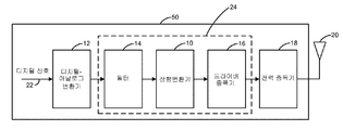
[0029] 도 1은 본 발명의 일 실시예에 따라 무선 통신 시스템에서 이용되는 무선 통신 디바이스(50)(이하, 대안적으로 디바이스로서 지칭됨)의 블록도이다. 디바이스(50)는 셀룰러 전화, 개인용 디지털 보조기기(PDA), 모뎀, 핸드헬드 디바이스, 랩톱 컴퓨터 등일 수 있다.[0029] FIG. 1 is a block diagram of a wireless communication device 50 (hereinafter alternatively referred to as a device) used in a wireless communication system in accordance with an embodiment of the present invention. The
[0030] 디바이스(50)는 임의의 주어진 시간에 다운 링크(DL) 및/또는 업링크(UL) 상에서 하나 이상의 기지국들과 통신할 수 있다. 다운링크(또는 순방향 링크)는 기지국으로부터 디바이스로의 통신 링크를 지칭한다. 업링크(또는 역방향 링크)는 디바이스로부터 기지국으로의 통신 링크를 지칭한다. [0030] The
[0031] 무선 통신 시스템은 이용 가능한 시스템 자원(예를 들어, 대역폭 및 전송 전력)을 공유함으로써 다수 사용자들과의 통신을 지원할 수 있는 다중-액세스 시스템일 수 있다. 이러한 시스템들의 예들은 CDMA(code division multiple access) 시스템들, TDMA(time division multiple access) 시스템들, FDMA(frequency division multiple access) 시스템들, OFDMA(orthogonal frequency division multiple access) 시스템들, SDMA(spatial division multiple access) 시스템들, 및 LTE(long term evolution) 시스템들을 포함한다.[0031] A wireless communication system may be a multi-access system capable of supporting communication with multiple users by sharing available system resources (e.g., bandwidth and transmission power). Examples of such systems are code division multiple access (CDMA) systems, time division multiple access (TDMA) systems, frequency division multiple access (FDMA) systems, orthogonal frequency division multiple access (OFDMA) systems, multiple access (LTE) systems, and long term evolution (LTE) systems.
[0032] 디바이스(50)는, 집합적으로 전송 채널을 형성하는 주파수 상향변환기/변조기(10), 디지털-아날로그 변환기(DAC)(12), 필터(14) 및 증폭기(16)를 부분적으로 포함하는 것으로 도시된다. 인입하는 디지털 신호(22)가 먼저 DAC(12)에 인가된다. 변환된 아날로그 신호가 필터(14)에 의해 필터링되고, 상향변환기/변조기(10)로 주파수 상향변환되고 그의 출력은 추가로 증폭기(16)에 의해 증폭된다. 증폭기(16)에 의해 생성된 증폭된 신호는 선택적으로, 안테나(20)에 의해 전송되기 이전에 전력 증폭기(18)를 사용하여 추가로 증폭될 수 있다. 특정한 실시예들에서, 드라이버 증폭기(16) 및/또는 전력 증폭기(18) 각각의 출력에서의 증폭된 신호는 또한 다른 블록들을 통과하기 전에 필터링(도시되지 않음)될 수 있다. The
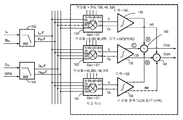
[0033] 도 2a는 본 발명의 일 예시적인 실시예에 따라 전송 체인(24)에 배치되는 다수의 컴포넌트들의 블록도이다. 전송 체인(24)은 필터(102, 104), 직교 상향변환기들(120, 122, 124), 드라이버 증폭기들(130, 132, 134), 및 결합기들(140, 142)을 부분적으로 포함하는 것으로 도시된다. 전송 체인(24)은 아래에서 추가로 설명되는 바와 같이, 자신이 수신한 신호들의 주파수를 상향변환하고 드라이버 증폭기들(130, 132, 및 134)에서 생성된 의사 고조파들을 억제하도록 적응된다. [0033] FIG. 2A is a block diagram of multiple components disposed in a transmit
[0034] 필터(102)는 필터링된 기저대역 신호들(Ibb_F 및 IBbb_F)을 생성하도록 I-채널 기저대역 신호들(Ibb 및 IBbb)로부터 원하지 않는 신호들을 필터링한다. 신호들(Ibb 및 IBbb)은 서로의 역(보수)일 수 있다. 마찬가지로, 필터(104)는 필터링된 기저대역 신호들(Qbb_F 및 QBbb_F)을 생성하도록 Q-채널 기저대역 신호들(Qbb 및 QBbb)로부터 원하지 않는 신호를 필터링할 수 있다. 서로에 대하여 90° 위상 시프트되는 4개의 필터링된 기저대역 신호들(Ibb_F, IBbb_F, Qbb_F 및 QBbb_F)은 직교 상향변환기들(120, 122, 124) 각각에 인가된다. 도시된 바와 같이, 직교 상향변환기(120)는 로컬 발진기(도시되지 않음)의 4개의 위상들(315, 135, 45, 225)을 수신한다. 직교 상향변환기(122)는 로컬 발진기의 4개의 위상들(0, 180, 90, 270)을 수신한다. 직교 상향변환기(124)는 로컬 발진기의 4개의 위상들(45, 225, 135, 315)을 수신한다. 이에 따라, 직교 상향변환기(120)에 의해 수신된 LO 신호의 4개의 위상들은 45°만큼 직교 상향변환기(122)에 의해 수신된 LO 신호의 대응하는 위상들에 앞선다. 마찬가지로, 직교 상향변환기(124)에 의해 수신된 LO 신호의 4개의 위상들은 45°만큼 직교 상향변환기(122)에 의해 수신된 LO 신호의 대응하는 위상들에 뒤처진다. [0034] The
[0035] 직교 상향변환기(120)는 RF 신호들(I1, Q1)을 생성하도록 주파수 상향변환을 수행하고; 직교 상향변환기(122)는 RF 신호들(I2, Q2)을 생성하도록 주파수 상향변환을 수행하고; 그리고 직교 상향변환기(124)는 RF 신호들(I3, Q3)을 생성하도록 주파수 상향변환을 수행한다. 증폭기(130)는 상보적 신호들(A 및 AB)의 쌍을 생성하도록 신호들(I1/Q1)을 증폭하고; 증폭기(132)는 상보적 신호들(B 및 BB)의 쌍을 생성하도록 신호들(I2/Q2)을 증폭하고; 그리고 증폭기(134)는 상보적 신호들(C 및 CB)의 쌍을 생성하도록 신호들(I3/Q3)을 증폭한다.[0035] The quadrature up-
[0036] 직교 상향변환기(120)에 인가된 로컬 발진기 신호의 4개의 위상들이 45°만큼 직교 상향변환기(122)에 인가된 로컬 발진기 신호의 대응하는 위상들에 앞서기 때문에, 신호(I1)는 45°만큼 신호(I2)에 앞서고 신호(Q1)는 45°만큼 신호(Q2)에 앞선다. 이에 따라, 신호(A)는 45°만큼 신호(C)에 앞서고 신호(AB)는 45°만큼 신호(CB)에 앞선다. 마찬가지로, 직교 상향변환기(124)에 인가된 로컬 발진기 신호의 4개의 위상들이 45°만큼 직교 상향변환기(122)에 인가된 로컬 발진기 신호의 대응하는 위상들에 뒤처지기 때문에, 신호(B)는 45°만큼 신호(C)에 뒤처지고 신호(BB)는 45°만큼 신호(CB)에 뒤처진다. Since [0036] quadrature up-converter group prior to the phase corresponding to the local oscillator signal applied to the quadrature upconverter (122) of four phases of local oscillator signals by 45 ° is applied to 120, the signal (I 1) The signal Q 1 precedes the signal I 2 by 45 ° and the signal Q 1 precedes the signal Q 2 by 45 °. Thus, the signal A precedes the signal C by 45 degrees and the signal AB precedes the signal CB by 45 degrees. Likewise, since the four phases of the local oscillator signal applied to the quadrature up-
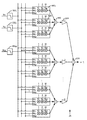
[0037] 도 2b는 본 발명의 일 예시적인 실시예에 따라 도 2a에서 예시된 전송 체인의 일반화된 블록도이다. 예시된 바와 같이, 일반적으로, 전송 체인(26)은, 각각이 M개의 입력 신호들 중 하나를 수신하고 출력 신호들(out1 내지 outM) 중 하나를 출력하는 M개의 필터들(202)을 포함할 수 있다. 각각의 출력 신호(예를 들어, out1)는 신호 및 그 신호의 역을 포함할 수 있다. 출력 신호들은 일반화된 상향변환기(2221 내지 222N)에 진입할 수 있다. 일반화된 상향변환기들(222) 각각은 M/2개의 더블 밸런스 믹서들(double-balanced mixers)을 포함할 수 있다. N개의 상향변환기들(222)의 출력은 N개의 증폭기들(2241 내지 224N)로 증폭될 수 있다. 증폭된 신호들은 그 후 출력(228)을 생성하도록 일반화된 결합기(226)로 결합될 수 있다. [0037] FIG. 2B is a generalized block diagram of the transmit chain illustrated in FIG. 2A, in accordance with an exemplary embodiment of the present invention. As illustrated, in general, the transmit
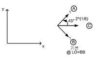
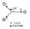
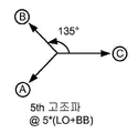
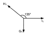
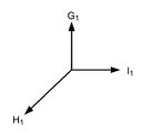
[0038] 도 3a는 로컬 발진기(LO)의 LO 주파수 및 BB의 기저대역 주파수, 즉 LO+BB에 의해 정의된 기본 주파수를 갖는 신호들(A, B 및 C)에 대응하는 3개의 페이저들(phasors)을 도시한다. 도 3a에서 알 수 있는 바와 같이, 이 기본 주파수에서, 신호(A)는 45°만큼 신호(C)에 앞서고 신호(B)는 45°만큼 신호(C)에 뒤처진다. 도 3b 및 도 3c는 3*(LO+BB)의 3차 고조파 주파수 및 5*(LO+BB)의 5차 고조파 주파수에서 동일한 3개의 페이저들을 각각 도시한다. 3차 고조파에 대해, 신호들(C와 A, 또는 B와 C)의 위상들 간의 차이는 3*45 = 135°이다. 5차 고조파에 대해, 신호들(C와 A, 또는 B와 C)의 위상들 간의 차이는 5*45 = 225°이다. [0038] Figure 3a shows three pagers (A, B, and C) corresponding to signals A, B, and C having a fundamental frequency defined by the LO frequency of the local oscillator LO and the baseband frequency of BB, phasors. As can be seen in Figure 3a, at this fundamental frequency, signal A precedes signal C by 45 ° and signal B lags signal C by 45 °. Figures 3b and 3c show three phasors at the third harmonic frequency of 3 * (LO + BB) and the same three phasors at the fifth harmonic frequency of 5 * (LO + BB), respectively. For the third harmonic, the difference between the phases of the signals (C and A, or B and C) is 3 * 45 = 135 °. For the fifth harmonic, the difference between the phases of the signals (C and A, or B and C) is 5 * 45 = 225 °.
[0039] 도 3a를 참조하면, LO+BB의 기본 및 원하는 주파수의 신호들(A, B, 및 C)에 대응하는 3개의 페이저들은 서로 보강한다는 것이 확인된다. 이에 따라, 신호들(A, B, C)을 결합/부가함으로써 생성되는 결합기(140)의 출력 신호(Outp)는 기본 주파수에서 강화된다.[0039] Referring to FIG. 3A, it is confirmed that three phasors corresponding to signals A, B, and C of the basic and desired frequencies of LO + BB reinforce each other. Accordingly, the output signal Outp of the
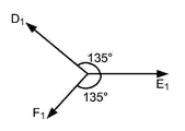
[0040] 도 3b를 참조하면, 실질적으로 3차 고조파를 억제하기 위해, X-축을 따라 페이저들(A 및 B)의 프로젝션(크기)의 합은 동일한 축을 따른 페이저(C)의 크기와 동일하게 되어야 한다는 것을 알 수 있다. 페이저들(A 및 B)이 1의 길이를 갖는다고 가정하면, 페이저들(C 및 A) 간의 각도 뿐만 페이저들(C 및 B) 간의 각도가 135°이기 때문에, 페이저들(A 및 B)의 각각의 x-컴포넌트는 ![]()
![]()
![]()
![]()
![]()
![]()
[0041] 증폭기(132)가 ![]()

![]()

![]()
![]()
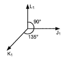
[0042] 도 3c를 참조하면, 신호들(A 및 B)의 y-컴포넌트들은 서로 상쇄한다는 것이 확인된다. 이에 따라, 5차 고조파를 실질적으로 억제하기 위해, 페이저들(A 및 B)의 x-컴포넌트들의 합은 페이저(C)의 x-컴포넌트와 동일하게 되어야 한다. 페이저들(A 및 B)이 1의 길이를 갖는다고 가정하면, 페이저들(C 및 A) 간의 각도뿐만 페이저들(C 및 B) 간의 각도가 225°이기 때문에, x-축에 따른 페이저들(A 및 B)의 각각의 크기는 ![]()
![]()
![]()
![]()
![]()
![]()
[0043] 증폭기(132)가 ![]()

![]()

![]()
![]()
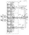
[0044] 일 실시예에서, 주파수 상향변환기들(120, 122, 124) 각각은, 다수의 상향변환기들을 차례로 포함하는 합성 고조파-거절 주파수 상향변환기(composite harmonic-rejective frequency upconverter)일 수 있다. 도 4a는 주파수 상향변환기의 다른 예시적인 실시예의 블록도이다. 도 4a의 전송 체인(24)은 필터(102, 104), 집합적으로 상향변환기(120)를 형성하는 직교 상향변환기들(1201, 1202, 1203), 집합적으로 상향변환기(122)를 형성하는 직교 상향변환기들(1221, 1222, 1223), 집합적으로 상향변환기(124)를 형성하는 직교 상향변환기들(1241, 1242, 1243), 드라이버 증폭기들(130, 132, 134) 및 결합기들(202, 204, 206, 208, 210, 212, 140, 142)을 부분적으로 포함하는 것으로 도시된다. [0044] In one embodiment, each of the
[0045] 도 4a의 전송 체인(24)은 도 2 및 3a-3c를 참조하여 위에서 설명된 바와 같이, 자신이 수신한 신호들의 주파수를 상향변환하고 3*(LO+BB)의 3차 고조파 주파수 또는 5*(LO+BB)의 5차 고조파 주파수를 억제하도록 적응된다. 도 4a의 전송 체인(24)은 상향변환기들에 의해 야기된 3*LO-BB의 3차 의사 믹싱 결과물, 상향변환기들에 의해 야기된 5*LO+BB의 5차 의사 믹싱의 결과물뿐만 아니라 드라이버 증폭기들에 의해 야기된 LO-3*BB의 원하는 않는 카운터-IM3 결과물을 억제하도록 추가로 적응된다. 도 4a의 실시예는 각각의 세트가 3개의 상향변환기들(총 9개의 상향변환기들)을 갖는 상향변환기들(120, 122, 124)의 3개의 세트들을 갖는 주파수 상향변환 회로를 참조하여 설명되지만, 다른 실시예들은 각각의 세트가 Q개의 상향변환기들을 포함하는 상향변환기들의 N개의 세트들을 가질 수 있다는 것이 이해되며, 여기서 N과 Q는 양의 정수들이다. 또한, 도 4a의 주파수 상향변환 회로는 각각의 세트가 LO 신호의 4개의 상이한 위상들을 갖는, LO 신호의 위상들의 9개의 세트들을 수신하는 것으로서 도시되지만, 다른 실시예들은 각각의 세트가 LO 신호의 M개의 상이한 위상들을 포함하는, LO 신호의 위상들의 NxQ개의 세트를 수신할 수 있다는 것이 이해되며, 여기서 N, Q 및 M은 양의 정수들이다. 특정 실시예들에 대해, LO 신호의 위상들의 NxQ개의 세트들 중 일부는 구별되고, 세트들 중 일부에 서로 유사할 수 있다. 예를 들어, N=3 및 Q=3인 경우, LO 신호의 위상들의 9개의 세트들 중에서, 5개의 세트들은 구별될 수 있고 4개의 세트들은 다른 세트들의 복제일 수 있다. [0045] The
[0046] 필터(102)는 I-채널 필터링된 기저대역 신호들(Ibb_F 및 IBbb_F)을 생성하도록 기저대역 신호들(Ibb 및 IBbb)로부터 원하지 않는 신호들을 필터링한다. 신호들(Ibb 및 IBbb)은 서로의 역일 수 있다. 마찬가지로, 필터(104)는 필터링된 기저대역 신호들(Qbb_F 및 QBbb_F)을 생성하도록 Q-채널 기저대역 신호들(Qbb 및 QBbb)로부터 원하지 않는 신호를 필터링할 수 있다. 서로에 대하여 90° 위상 시프트되는 4개의 필터링된 기저대역 신호들(Ibb_F, IBbb_F, Qbb_F 및 QBbb_F)은 직교 상향변환기들(1201, 1202, 1203, 1221, 1222, 1223, 1241, 1242, 1243) 각각에 인가된다. [0046] The
[0047] 도시된 바와 같이, 상향변환기(1201)는 로컬 발진기의 4개의 위상들(270, 90, 0, 180)을 수신하고; 상향변환기(1202)는 로컬 발진기의 4개의 위상들(315, 135, 45, 225)을 수신하고; 상향변환기(1203)는 로컬 발진기의 4개의 위상들(0, 180, 90, 270)을 수신하고; 상향변환기(1221)는 로컬 발진기의 4개의 위상들(315, 135, 45, 225)을 수신하고; 상향변환기(1222)는 로컬 발진기의 4개의 위상들(0, 180, 90, 270)을 수신하고; 상향변환기(1223)는 로컬 발진기의 4개의 위상들(45, 225, 135, 315)을 수신하고; 상향변환기(1241)는 로컬 발진기의 4개의 위상들(0, 180, 90, 270)을 수신하고; 상향변환기(1242)는 로컬 발진기의 4개의 위상들(45, 225, 135, 315)을 수신하고; 및 상향변환기(1243)는 로컬 발진기(LO)의 4개의 위상들(90, 270, 180, 0)을 수신한다. As shown, up-
[0048] 이에 따라, 상향변환기(1201)에 의해 수신된 LO 신호의 4개의 위상들은 45°만큼 상향변환기(1202)에 의해 수신된 LO 신호의 대응하는 위상들에 앞서고, 상향변환기(1203)에 의해 수신된 LO 신호의 4개의 위상들은 45°만큼 직교 상향변환기(1202)에 의해 수신된 LO 신호의 대응하는 위상들에 뒤처진다. 유사하게, 상향변환기(1221)에 의해 수신된 LO 신호의 4개의 위상들은 45°만큼 상향변환기(1222)에 의해 수신된 LO 신호의 대응하는 위상들에 앞서고, 상향변환기(1223)에 의해 수신된 LO 신호의 4개의 위상들은 45°만큼 직교 상향변환기(1222)에 의해 수신된 LO 신호의 대응하는 위상들에 뒤처진다. 마찬가지로, 상향변환기(1241)에 의해 수신된 LO 신호의 4개의 위상들은 45°만큼 상향변환기(1242)에 의해 수신된 LO 신호의 대응하는 위상들에 앞서고, 상향변환기(1243)에 의해 수신된 LO 신호의 4개의 위상들은 45°만큼 직교 상향변환기(1242)에 의해 수신된 LO 신호의 대응하는 위상들에 뒤처진다. Thus, the four phases of the LO signal received by the up-
[0049] 또한, 상향변환기(120i)에 의해 수신된 LO 신호의 4개의 위상들은 45°만큼 직교 상향변환기(122i)에 의해 수신된 LO 신호의 대응하는 위상들에 앞서며, 여기서 i는 이 예시적인 실시예에서 1-3의 다양한 정수이다. 예를 들어, 상향변환기(1202)에 의해 수신된 LO 신호의 4개의 위상들(315, 135, 45, 225)은 45°만큼 직교 상향변환기(1222)에 의해 수신된 LO 신호의 대응하는 4개의 위상들(0, 180, 90, 270)에 앞선다. 마찬가지로, 상향변환기(124i)에 의해 수신된 LO 신호의 4개의 위상들은 45°만큼 직교 상향변환기(122i)에 의해 수신된 LO 신호의 대응하는 위상들에 뒤처진다. 예를 들어, 상향변환기(1242)에 의해 수신된 LO 신호의 4개의 위상들(45, 225, 135, 315)은 45°만큼 직교 상향변환기(1222)에 의해 수신된 LO 신호의 대응하는 위상들(0, 180, 90, 270)에 뒤처진다. [0049] Also, the four phases of the LO signal received by the up-
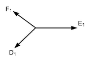
[0050] 상향변환기(1201)는 상향변환된 동위상 및 역 RF 신호들(G1, G2)을 생성하도록 주파수 상향변환을 수행하고; 상향변환기(1202)는 상향변환된 동위상 및 역 RF 신호들(H1, H2)을 생성하도록 주파수 상향변환을 수행하고; 상향변환기(1203)는 상향변환된 동위상 및 그의 역 RF 신호들(I1, I2)을 생성하도록 주파수 상향변환을 수행하고; 상향변환기(1221)는 상향변환된 동위상 및 역 RF 신호들(D1, D2)을 생성하도록 주파수 상향변환을 수행하고; 상향변환기(1222)는 상향변환된 동위상 및 역 RF 신호들(E1, E2)을 생성하도록 주파수 상향변환을 수행하고; 상향변환기(1223)는 상향변환된 동위상 및 역 RF 신호들(F1, F2)을 생성하도록 주파수 상향변환을 수행하고; 상향변환기(1241)는 상향변환된 동위상 및 역 RF 신호들(J1, J2)을 생성하도록 주파수 상향변환을 수행하고; 상향변환기(1242)는 상향변환된 동위상 및 역 RF 신호들(K1, K2)을 생성하도록 주파수 상향변환을 수행하고; 및 상향변환기(1243)는 상향변환된 동위상 및 역 RF 신호들(L1, L2)을 생성하도록 주파수 상향변환을 수행한다. [0050] Up-
[0051] 결합기(202)는 신호(M)를 생성하도록 신호들(G1, H1, I1)을 부가/결합하도록 적응되고; 결합기(204)는 신호(N)를 생성하도록 신호들(G2, H2, I2)을 부가/결합하도록 적응되고; 결합기(206)는 신호(O)를 생성하도록 신호들(D1, E1, F1)을 부가/결합하도록 적응되고; 결합기(208)는 신호(p)를 생성하도록 신호들(D2, E2, F2)을 부가/결합하도록 적응되고; 결합기(210)는 신호(S)를 생성하도록 신호들(J1, K1, L1)을 부가/결합하도록 적응되고; 및 결합기(212)는 신호(T)를 생성하도록 신호들(J2, K2, L2)을 부가/결합하도록 적응된다. 증폭기(130)는 상보적 신호들(A 및 AB)의 쌍을 생성하도록 신호들(M 및 N)을 증폭하고; 증폭기(132)는 상보적 신호들(B 및 BB)의 쌍을 생성하도록 신호들(O 및 P)을 증폭하고; 및 증폭기(134)는 상보적 신호들(C 및 CB)의 쌍을 생성하도록 신호들(S 및 T)을 증폭한다. [0051] The
[0052] 직교 상향변환기(1201)에 인가된 로컬 발진기 신호의 4개의 위상들이 45°만큼 직교 상향변환기(1202)에 인가된 로컬 발진기 신호의 대응하는 위상들에 앞서기 때문에, 신호들(G1 및 G2)은 각각 45°만큼 신호들(H1 및 H2)에 앞선다. 마찬가지로, 직교 상향변환기(1203)에 인가된 로컬 발진기 신호의 4개의 위상들이 45°만큼 직교 상향변환기(1202)에 인가된 로컬 발진기 신호의 대응하는 위상들에 뒤처지기 때문에, 신호들(I1 및 I2)은 각각 45°만큼 신호들(H1 및 H2)에 뒤처진다. 동일한 이유로, 신호들(D1 및 D2)은 각각 45°만큼 신호들(E1 및 E2)에 앞서고, 신호들(F1 및 F2)은 각각 45°만큼 신호들(E1 및 E2)에 뒤처진다. 마찬가지로, 신호들(J1 및 J2)은 각각 45°만큼 신호들(K1 및 K2)에 앞서고, 신호들(L1 및 L2)은 각각 45°만큼 신호들(K1 및 K2)에 뒤처진다. Since [0052] quadrature up-converter group prior to the phase corresponding to the local oscillator signal applied to the four phases are quadrature upconverter (120 2) by 45 ° of the local oscillator signal applied to the (120 1), the signal ( G 1 and G 2 are ahead of the signals H 1 and H 2 by 45 °, respectively. Similarly, since the four phases of the local oscillator signal applied to quadrature up-
[0053] 도 4b는 본 발명의 일 예시적인 실시예에 따라 도 4a에서 예시된 전송 체인의 일반화된 블록도이다. 예시된 바와 같이, 일반적으로, 전송 체인(28)은, 각각이 M개의 입력 신호들 중 하나를 수신하고 출력 신호들(out1 내지 outM) 중 하나를 출력하는 M개의 필터들(202)을 포함할 수 있다. 각각의 출력 신호(예를 들어, out1)는 신호 및 그 신호의 역을 포함할 수 있다. 출력 신호들은 일반화된 상향변환기들(예를 들어, 4401 내지 440Q)의 N개의 세트들 각각에 진입할 수 있다. 일반화된 상향변환기들(440) 각각은 M/2개의 더블 밸런스 믹서들 또는 M개의 단일 밸런스 믹서들을 포함할 수 있다. Q개의 상향변환기들(440)의 출력은 증폭기(2241)로 증폭되기 이전에, 결합기(450)로 결합될 수 있다. N개의 증폭기들(2241 내지 224N)의 출력들은 그 후 출력(228)을 생성하도록 일반화된 결합기(226)로 결합될 수 있다. [0053] FIG. 4B is a generalized block diagram of the transport chain illustrated in FIG. 4A in accordance with an exemplary embodiment of the present invention. As illustrated, generally, the transmit
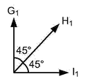
[0054] 도 5a는 로컬 발진기(LO)의 LO 주파수 및 BB의 기저대역 주파수, 즉 LO+BB에 의해 정의된 기본 주파수를 갖는 신호들(I1, G1 및 H1)과 연관되는 3개의 페이저들을 도시한다. 도 5a에서 도시된 바와 같이, 이 기본 주파수에서, 신호(G1)는 45°만큼 신호(H1)에 앞서고 신호(I1)는 45°만큼 신호(H1)에 뒤처진다. 도 5b는 LO+BB의 기본 주파수를 갖는 신호들(E1, F1 및 D1)과 연관된 3개의 페이저들을 도시한다. 도 5b에서 도시된 바와 같이, 이 기본 주파수에서, 신호(D1)는 45°만큼 신호(E1)에 앞서고 신호(F1)는 45°만큼 신호(E1)에 뒤처진다. 도 5c는 LO+BB의 기본 주파수를 갖는 신호들(J1, K1 및 L1)과 연관된 3개의 페이저들을 도시한다. 도 5c에서 도시된 바와 같이, 이 기본 주파수에서, 신호(J1)는 45°만큼 신호(K1)에 앞서고 신호(L1)는 45°만큼 신호(K1)에 뒤처진다. [0054] FIG. 5A is a graph showing the relationship between the LO frequency of the local oscillator (LO) and the baseband frequency of BB, ie, three signals (I 1 , G 1 and H 1 ) Lt; / RTI > As shown in FIG. 5A, at this fundamental frequency, the signal G 1 precedes the signal H 1 by 45 ° and the signal I 1 lies behind the signal H 1 by 45 °. FIG. 5B shows three phasors associated with signals (E 1 , F 1 and D 1 ) having a fundamental frequency of LO + BB. As shown in FIG. 5B, at this fundamental frequency, the signal D 1 precedes the signal E 1 by 45 ° and the signal F 1 lies behind the signal E 1 by 45 °. Figure 5c shows three phasors associated with signals (J 1 , K 1 and L 1 ) having a fundamental frequency of LO + BB. As shown in FIG. 5C, at this fundamental frequency, the signal J 1 precedes the signal K 1 by 45 ° and the signal L 1 lies behind the signal K 1 by 45 °.
[0055] 도 6a는 (3*LO-BB)의 의사 상향변환 믹싱 결과물 주파수에서 신호들(G1, H1, I1)과 연관된 3개의 페이저들을 도시한다. 신호(H1)의 값(진폭)은 신호들(G1 및 I1)의 각각의 값보다 √2배 더 크게 되도록 선택된다. 따라서, 신호(H1)의 y-컴포넌트는 신호(G1)를 상쇄하고, 신호(H1)의 x-컴포넌트는 신호(I1)를 상쇄한다. 도 6b는 (3*LO-BB)의 의사 상향변환 믹싱 결과물 주파수에서 신호들(D1, E1, F1)과 연관된 3개의 페이저들을 도시한다. 신호(E1)의 값은 신호들(D1 및 F1)의 각각의 값보다 √2배 더 크게 되도록 선택된다. 따라서, 신호들(D1 및 F1)의 y-컴포넌트들은 서로를 상쇄한다. 또한, 신호들(D1 및 F1)의 x-컴포넌트들의 합은 신호(E1)를 상쇄한다. 도 7c는 (3*LO-BB)의 의사 상향변환 믹싱 결과물 주파수에서 신호들(J1, K1, L1)과 연관된 3개의 페이저들을 도시한다. 신호(K1)의 값은 신호들(L1 및 J1)의 각각의 값보다 √2배 더 크게 되도록 선택된다. 따라서, 신호(K1)의 x-컴포넌트는 신호(J1)를 상쇄하고, 신호(K1)의 y-컴포넌트는 신호(L1)를 상쇄한다. 이에 따라, 주파수(3*LO-BB)에서 의사 상향변환 믹싱 결과물은 (i) 결합기들(202, 204)의 출력들(M 및 N), (ii) 결합기들(206, 208)의 출력들(O 및 P); 및 (iii) 결합기들(201, 212)의 출력들(S, T)에서 실질적으로 감소된다. 즉, 본 발명의 일 양상에 따라, 주파수(3*LO-BB)에서 의사 상향변환 믹싱 결과물은 결합기들의 출력에서, 즉, 증폭기들(130, 132, 134)의 입력들에서 상쇄되거나 실질적으로 감소된다. [0055] FIG. 6a shows three phasors associated with signals (G 1 , H 1 , I 1 ) at the pseudo upconverted mixing output frequency of (3 * LO-BB). The value (amplitude) of the signal H 1 is chosen to be √2 times larger than the respective value of the signals G 1 and I 1 . Accordingly, the signal components in the x- y- component offsets the signal (G 1), and the signal (H 1) of (H 1) is offset by a signal (I 1). FIG. 6B shows three phasors associated with signals D 1 , E 1 , F 1 at the pseudo upconverted mixing output frequency of (3 * LO-BB). The value of the signal E 1 is chosen to be √2 times larger than the respective value of the signals D 1 and F 1 . Thus, the y-components of the signals D 1 and F 1 cancel each other out. In addition, the sum of the x-components of the signals D 1 and F 1 offsets the signal E 1 . Figure 7C shows three phasors associated with signals (J 1 , K 1 , L 1 ) at the pseudo upconverted mixing output frequency of (3 * LO-BB). The value of the signal K 1 is selected to be 2 times larger than the respective value of the signals L 1 and J 1 . Thus, y- components of the signal (K 1) x- component canceling signal, and the signal (K 1) to (J 1) is offset in a signal (L 1). Thus, the pseudo upconversion mixing result at frequency (3 * LO-BB) is (i) the outputs M and N of
[0056] 도 7a는 (5*LO+BB)의 의사 상향변환 결과물 주파수에서 신호들(G1, H1, I1)과 연관된 3개의 페이저들을 도시한다. 신호(H1)의 값은 신호들(G1 및 H1)의 각각의 값보다 √2배 더 크게 되도록 선택된다. 따라서, 신호(H1)의 y-컴포넌트는 신호(G1)를 상쇄하고, 신호(H1)의 x-컴포넌트는 신호(I1)를 상쇄한다. 도 7b는 (5*LO+BB)의 의사 상향변환 결과물 주파수에서 신호들(D1, E1, F1)과 연관된 3개의 페이저들을 도시한다. 신호(E1)의 값은 신호들(D1 및 F1)의 각각의 값보다 √2배 더 크게 되도록 선택된다. 따라서, 신호들(D1 및 F1)의 y-컴포넌트들은 서로를 상쇄한다. 또한, 신호들(D1 및 F1)의 x-컴포넌트들의 합은 신호(E1)를 상쇄한다. [0056] FIG. 7a shows three phasors associated with signals (G 1 , H 1 , I 1 ) at the pseudo upconversion output frequency of (5 * LO + BB). Value of the signal (H 1) is selected to be √2 times larger than each value of the signals (G 1 and H 1). Accordingly, the signal components in the x- y- component offsets the signal (G 1), and the signal (H 1) of (H 1) is offset by a signal (I 1). Figure 7B shows three phasors associated with signals (D 1 , E 1 , F 1 ) at the pseudo upconversion output frequency of (5 * LO + BB). The value of the signal E 1 is chosen to be √2 times larger than the respective value of the signals D 1 and F 1 . Thus, the y-components of the signals D 1 and F 1 cancel each other out. In addition, the sum of the x-components of the signals D 1 and F 1 offsets the signal E 1 .
[0057] 도 7c는 (5*LO+BB)의 의사 상향변환 결과물 주파수에서 신호들(J1, K1, L1)과 연관된 3개의 페이저들을 도시한다. 신호(K1)의 값은 신호들(L1 및 J1)의 각각의 값보다 √2배 더 크게 되도록 선택된다. 따라서, 신호(K1)의 x-컴포넌트는 신호(J1)를 상쇄하고, 신호(K1)의 y-컴포넌트는 신호(L1)을 상쇄한다. 이에 따라, 주파수(5*LO+BB)에서 의사 상향변환 결과물들은 (i) 결합기들(202, 204)의 출력들(M 및 N), (ii) 결합기들(206, 208)의 출력들(O 및 P); 및 (iii) 결합기들(201, 212)의 출력들(S, T)에서 실질적으로 상쇄된다. 즉, 본 발명의 일 양상에 따라, 주파수(5*LO+BB)에서 의사 상향변환 결과물은 결합기들의 출력에서, 즉, 증폭기들의 입력들에서 상쇄되거나 실질적으로 감소된다. [0057] FIG. 7C shows three phasors associated with signals (J 1 , K 1 , L 1 ) at the pseudo upconversion output frequency of (5 * LO + BB). The value of the signal K 1 is selected to be 2 times larger than the respective value of the signals L 1 and J 1 . Thus, component x- y- components of the offset, and the signal (K 1) the signals (J 1) of the signal (K 1) is offset signal (L 1). Accordingly, the pseudo up-conversion results at frequency (5 * LO + BB) are (i) the outputs M and N of
[0058] 제안된 방법들은 또한 주파수(LO-3BB)의 원하지 않는 컴포넌트들을 거절한다는 것이 주의되어야 한다. LO+BB 및 3*LO-BB에서 스펙트럼 컴포넌트를 통한 입력 신호들의 상호변조의 결과로 인한 증폭기들(130, 132, 134)에서의 3차 비선형성의 존재로 인해, 주파수(LO-3BB)에서 원하지 않는 컴포넌트가 생성된다. 도 4a에서 예시된 바와 같은 실시예는 결합기 출력들(202, 204, 206, 208, 210, 및 212)에서 설계에 의해 3*LO-BB 컴포넌트들을 거절한다. 3*LO-BB의 컴포넌트의 이러한 거절의 결과로서, 실질적인 LO-3*BB 결과물들이 증폭기들(130, 132, 134)의 출력들에서 생성되지 않을 수 있다. [0058] It should be noted that the proposed methods also reject unwanted components of the frequency (LO-3BB). (LO-3BB) due to the presence of third order nonlinearities in the
[0059] 도 8은 본 발명의 일 실시예에 따른 통신 방법에 대한 흐름도(200)이다. 통신을 수행하기 위해, 전송될 신호의 M개의 위상들은 N개의 상향변환기들에 인가된다(202). LO 신호의 위상들의 N개의 세트들 중 하나는 또한 N개의 상향변환기들 각각에 인가된다(204). 위상들의 N개의 세트들 각각은 LO 신호의 M개의 위상들 중 상이한 하나를 포함한다. 각각의 상향변환기의 출력은 N개의 증폭된 신호들을 생성하기 위해 연관된 증폭기에 인가된다(206). 증폭기들의 적어도 하나의 이득은 잔여 증폭기들의 이득과 상이한 값들로 세팅된다(208). 증폭된 신호들은 전송될 상향변환된 신호의 실질적으로 감소된 고조파를 갖는 출력 신호를 생성하도록 결합된다(216). [0059] FIG. 8 is a flowchart 200 of a communication method according to an embodiment of the present invention. To perform the communication, the M phases of the signal to be transmitted are applied to the N up-converters (202). One of the N sets of phases of the LO signal is also applied to each of the N up-converters (204). Each of the N sets of phases includes a different one of the M phases of the LO signal. The output of each upconverter is applied to an associated amplifier to generate N amplified signals (206). At least one gain of the amplifiers is set to a different value than the gain of the residual amplifiers (208). The amplified signals are combined (216) to produce an output signal having a substantially reduced harmonic of the upconverted signal to be transmitted.
[0060] 도 9는 본 발명의 일 실시예에 따른 통신 방법에 대한 흐름도(200)이다. 통신을 수행하기 위해, 전송될 신호의 M개의 위상들은 상향변환기들의 N개의 세트들에 인가된다(304). N개의 세트들 각각은 Q개의 상향변환기들 포함한다. 예시된 바와 같이, 신호의 M개의 위상들은 N개의 세트들 각각의 Q개의 상향변환기들 각각에 인가된다. 로컬 발진기 신호의 위상들의 NxQ개의 세트들 중 하나가 또한 NxQ개의 상향변환기들 각각의 인가된다(306). NxQ개의 세트들 각각은 LO 신호의 M개의 위상들을 포함한다. Q개의 상향변환기들 각각은 이에 응답하여 상향변환된 동위상 신호 및 상향변환된 역 신호를 생성한다. 그 후, N개의 세트들 각각의 Q개의 상향변환기들에 의해 생성된 Q개의 동위상 신호들은 N개의 결합된 동위상 신호들을 생성하도록 결합된다(308). N개의 세트들 각각의 Q개의 상향변환기들에 의해 생성된 Q개의 역 신호들은 또한 N개의 결합된 역 신호들을 생성하도록 결합된다(310). [0060] FIG. 9 is a flowchart 200 of a communication method according to an embodiment of the present invention. To perform the communication, the M phases of the signal to be transmitted are applied to N sets of upconverters (304). Each of the N sets includes Q up-converters. As illustrated, the M phases of the signal are applied to each of the Q up-converters of each of the N sets. One of the NxQ sets of phases of the local oscillator signal is also applied (306) to each of the NxQ up-converters. Each of the NxQ sets includes M phases of the LO signal. Each of the Q up-converters generates an up-converted in-phase signal and an up-converted inverse signal in response thereto. The Q in-phase signals generated by the Q up-converters of each of the N sets are then combined (308) to produce N combined in-phase signals. The Q inverse signals generated by the Q upconverters of each of the N sets are also combined 310 to produce N combined inverse signals.
[0061] 본 발명의 위의 실시예들은 예시적이며 제한적이지 않다. 본 발명의 실시예들은 상향변환기들의 수, LO 위상들의 세트들의 수, 또는 각각의 이러한 세트 내의 LO 위상들의 수에 의해 제한되지 않는다. 본 발명의 실시예들은 각각의 세트에서 사용된 로컬 발진기의 임의의 특정한 위상들에 의해서도 제한되지 않는다. 다른 부가들, 제외들 또는 변형들은 본 개시를 고려하여 명백하며, 첨부된 청구항들의 범위 내에 있도록 의도된다. [0061] The above embodiments of the present invention are illustrative and not restrictive. Embodiments of the present invention are not limited by the number of upconverters, the number of sets of LO phases, or the number of LO phases in each such set. Embodiments of the present invention are not limited by any particular phase of the local oscillator used in each set. Other additions, subtractions or variations are obvious in light of this disclosure, and are intended to be within the scope of the appended claims.
Claims (60)
전송될 기저대역 신호의 M개의 위상들을 각각 수신하는 N개의 상향변환기들 ― 각각의 상향변환기는 추가로 로컬 발진기(LO) 신호의 위상들의 N개의 세트들 중 상이한 하나를 수신하고, 상기 N개의 세트들 각각은 상기 LO 신호의 M개의 상이한 위상들을 포함함 ― ;
N개의 증폭된 신호들을 생성하기 위해 상기 N개의 상향변환기들의 상이한 하나에 각각 응답하는 N개의 증폭기들; 및
출력 신호를 생성하도록 상기 N개의 증폭된 신호들을 결합하도록 적응되는 적어도 하나의 결합기
를 포함하고,
LO 신호 주파수와 기저대역 신호 주파수의 합의 배수 또는 상기 LO 신호 주파수와 상기 기저대역 신호 주파수 간의 차이의 배수에서 주파수 컴포넌트 하락(frequency component falling)은 상기 N개의 증폭기들 중 적어도 제 1 증폭기의 이득이 상기 N개의 증폭기들 중 잔여 증폭기들의 이득과 상이하게 되도록 선택함으로써 상기 출력 신호로부터 실질적으로 억제되고,
N 및 M은 1 초과의 정수들인,
전송 경로를 갖는 통신 디바이스.1. A communication device having a transmission path,
N up-converters each receiving M phases of the baseband signal to be transmitted, each up-converter further receiving a different one of the N sets of phases of the local oscillator (LO) signal, Each of which comprises M different phases of the LO signal;
N amplifiers each responsive to a different one of the N up-converters to produce N amplified signals; And
At least one coupler adapted to combine the N amplified signals to produce an output signal,
Lt; / RTI >
Wherein a frequency component falling at a multiple of the sum of the LO signal frequency and the baseband signal frequency or a multiple of the difference between the LO signal frequency and the baseband signal frequency is determined by determining whether the gain of at least the first amplifier Is substantially suppressed from the output signal by selecting to differ from the gain of the remaining ones of the N amplifiers,
N and M are integers greater than 1,
A communication device having a transmission path.
전송될 제 1 필터링된 동위상 신호(in-phase signal)를 생성하도록 기저대역 동위상 신호를 수신하는 제 1 필터; 및
전송될 제 2 필터링된 직교-위상 신호(quadrature-phase signal)를 생성하도록 기저대역 직교-위상 신호를 수신하는 제 2 필터
를 더 포함하는,
전송 경로를 갖는 통신 디바이스.The method according to claim 1,
A first filter for receiving a baseband in-phase signal to produce a first filtered in-phase signal to be transmitted; And
A second filter for receiving a baseband quadrature-phase signal to produce a second filtered quadrature-phase signal to be transmitted;
≪ / RTI >
A communication device having a transmission path.
상기 기저대역 동위상 신호는 상보적 신호들의 제 1 쌍을 포함하고,
상기 기저대역 직교-위상 신호는 상보적 신호들의 제 2 쌍을 포함하는,
전송 경로를 갖는 통신 디바이스.3. The method of claim 2,
Wherein the baseband in-phase signal comprises a first pair of complementary signals,
Wherein the baseband quadrature-phase signal comprises a second pair of complementary signals,
A communication device having a transmission path.
N은 3이고 M은 4인,
전송 경로를 갖는 통신 디바이스.The method according to claim 1,
N is 3 and M is 4,
A communication device having a transmission path.
3차 고조파를 제거하기 위해, 제 1 및 제 2 증폭기들이 동일한 이득을 갖도록 선택되고, 제 3 증폭기는 상기 제 1 및 제 2 증폭기들의 이득보다 더 큰 이득을 갖도록 선택되는,
전송 경로를 갖는 통신 디바이스.5. The method of claim 4,
The first and second amplifiers are selected to have the same gain and the third amplifier is selected to have a gain greater than the gain of the first and second amplifiers,
A communication device having a transmission path.
상기 제 3 증폭기의 이득은 실질적으로 상기 제 1 및 제 2 증폭기들의 이득의
전송 경로를 갖는 통신 디바이스.6. The method of claim 5,
Wherein the gain of the third amplifier is substantially equal to the gain of the first and second amplifiers.
A communication device having a transmission path.
상기 제 3 증폭기의 이득은 실질적으로 상기 제 1 및 제 2 증폭기들의 이득의
전송 경로를 갖는 통신 디바이스.6. The method of claim 5,
Wherein the gain of the third amplifier is substantially equal to the gain of the first and second amplifiers.
A communication device having a transmission path.
제 1 세트의 상기 LO 신호의 4개의 위상들은 45°만큼 제 2 세트의 상기 LO 신호의 대응하는 4개의 위상들에 앞서는,
전송 경로를 갖는 통신 디바이스.6. The method of claim 5,
The four phases of the LO signal of the first set are prior to the corresponding four phases of the LO signal of the second set by 45 degrees,
A communication device having a transmission path.
제 3 세트의 상기 LO 신호의 4개의 위상들은 45°만큼 상기 제 2 세트의 상기 LO 신호의 대응하는 4개의 위상들에 뒤처지는,
전송 경로를 갖는 통신 디바이스.9. The method of claim 8,
The four phases of the LO signal of the third set lag behind the corresponding four phases of the LO signal of the second set by 45 degrees,
A communication device having a transmission path.
상기 제 1 세트의 LO 신호의 4개의 위상들은 315, 135, 45, 225도이고, 상기 제 2 세트의 LO 신호의 4개의 위상들은 0, 180, 90, 270도이며, 상기 제 3 세트의 LO 신호의 4개의 위상들은 45, 225, 135, 315도인,
전송 경로를 갖는 통신 디바이스.10. The method of claim 9,
Wherein the four phases of the first set of LO signals are 315, 135, 45, 225 degrees and the four phases of the second set LO signals are 0, 180, 90, 270 degrees, The four phases of the signal are 45, 225, 135, 315 degrees,
A communication device having a transmission path.
상향변환기들의 N개의 세트들 ― 각각의 세트는 Q개의 상향변환기들을 포함하고, 상기 N개의 세트들 각각의 Q개의 상향변환기들 각각은 전송될 기저대역 신호의 M개의 위상들을 수신하고, 상기 N개의 세트들 각각의 Q개의 상향변환기들 각각은 추가로 로컬 발진기(LO) 신호의 위상들의 NxQ개의 세트들 중 하나를 수신하고, 상기 NxQ개의 세트들 각각은 상기 LO 신호의 M개의 위상들을 포함하고, 상기 Q개의 상향변환기들 각각은 상향변환된 동위상 신호 및 상향변환된 역 신호를 생성함 ― ; 및
결합기들의 N개의 세트들
을 포함하고,
각각의 세트는 상향변환기들의 N개의 세트들 중 상이한 하나와 연관되고,
각각의 세트의 제 1 결합기는, 상기 제 1 결합기가 그의 연관된 상향변환기들로부터 수신한 Q개의 동위상 신호들을 결합하고,
각각의 세트의 제 2 결합기는, 상기 제 2 결합기가 그의 연관된 상향변환기들로부터 수신한 Q개의 역 신호들을 결합하고,
Q, M 및 N은 양의 정수들이고,
LO 신호 및 상기 기저대역 신호의 합의 배수 또는 상기 LO 신호와 상기 기저대역 신호 간의 차이의 배수에서 주파수 컴포넌트 하락은 결합된 동위상 및 역 신호들로부터 실질적으로 억제되는,
전송 경로를 갖는 통신 디바이스. 1. A communication device having a transmission path,
N sets of up-converters, each set comprising Q up-converters, each of the Q up-converters of each of the N sets receiving M phases of the baseband signal to be transmitted, Each of the Q up-converters of each of the sets further receiving one of N x Q sets of phases of a local oscillator (LO) signal, each of the N x Q sets comprising M phases of the LO signal, Each of the Q up-converters generating up-converted in-phase signals and up-converted inverse signals; And
N sets of combiners
/ RTI >
Each set being associated with a different one of the N sets of upconverters,
The first combiner of each set combines Q in-phase signals received by the first combiner from its associated upconverters,
The second combiner of each set combines the Q inverse signals received by the second combiner from its associated upconverters,
Q, M, and N are positive integers,
Wherein a frequency component drop at a multiple of the sum of the LO signal and the baseband signal or a multiple of the difference between the LO signal and the baseband signal is substantially suppressed from combined in-
A communication device having a transmission path.
전송될 제 1 필터링된 동위상 신호를 생성하도록 기저대역 동위상 신호를 수신하는 제 1 필터; 및
전송될 제 2 필터링된 직교-위상의 신호를 생성하도록 기저대역 직교-위상 신호를 수신하는 제 2 필터
를 더 포함하는,
전송 경로를 갖는 통신 디바이스. 12. The method of claim 11,
A first filter for receiving a baseband in-phase signal to produce a first filtered in-phase signal to be transmitted; And
A second filter for receiving a baseband quadrature-phase signal to produce a second filtered quadrature-phase signal to be transmitted;
≪ / RTI >
A communication device having a transmission path.
상기 기저대역 동위상 신호는 상보적 신호들의 제 1 쌍을 포함하고, 상기 기저대역 직교-위상 신호는 상보적 신호들의 제 2 쌍을 포함하는,
전송 경로를 갖는 통신 디바이스.13. The method of claim 12,
Wherein the baseband in-phase signal comprises a first pair of complementary signals and the baseband quadrature-phase signal comprises a second pair of complementary signals.
A communication device having a transmission path.
N 및 Q 각각은 3과 동일한,
전송 경로를 갖는 통신 디바이스.12. The method of claim 11,
N and Q are each equal to 3,
A communication device having a transmission path.
상기 LO 신호의 위상들의 NxQ개의 세트들은 5개의 구별되는 세트들을 포함하고, M은 4와 동일한,
전송 경로를 갖는 통신 디바이스.15. The method of claim 14,
Wherein the NxQ sets of phases of the LO signal comprise five distinct sets, M is equal to 4,
A communication device having a transmission path.
N개의 증폭기들
을 더 포함하고,
각각은 결합기들의 N개의 세트들 중 상이한 하나와 연관되고, 각각의 증폭기는 자신이 그의 결합기들의 연관된 세트로부터 수신한 신호 및 그의 역을 증폭하도록 적응되는,
전송 경로를 갖는 통신 디바이스.12. The method of claim 11,
N amplifiers
Further comprising:
Each associated with a different one of the N sets of combiners, each amplifier being adapted to amplify the signal it receives from its associated set of combiners and its inverse,
A communication device having a transmission path.
상기 증폭기들 중 적어도 하나의 이득은 실질적으로 (N-1)개의 잔여 증폭기들의 이득의
전송 경로를 갖는 통신 디바이스.17. The method of claim 16,
Wherein the gain of at least one of the amplifiers is substantially equal to the gain of the (N-1)
A communication device having a transmission path.
상기 증폭기들 중 적어도 하나의 이득은 실질적으로 (N-1)개의 잔여 증폭기들의 이득의
전송 경로를 갖는 통신 디바이스.17. The method of claim 16,
Wherein the gain of at least one of the amplifiers is substantially equal to the gain of the (N-1)
A communication device having a transmission path.
상기 N개의 세트들 각각의 제 1 상향변환기에 의해 수신된 LO 신호의 4개의 위상들은, 45°만큼 상기 세트의 제 2 상향변환기에 의해 수신된 LO 신호의 대응하는 4개의 위상들에 앞서고, 상기 N개의 세트들 각각의 제 3 상향변환기에 의해 수신된 LO 신호의 4개의 위상들은, 45°만큼 상기 세트의 제 2 상향변환기에 의해 수신된 LO 신호의 대응하는 4개의 위상들에 뒤처지는,
전송 경로를 갖는 통신 디바이스.15. The method of claim 14,
The four phases of the LO signal received by the first upconverter of each of the N sets are ahead of the corresponding four phases of the LO signal received by the second upconverter of the set by 45 degrees, The four phases of the LO signal received by the third upconverter of each of the N sets are shifted by 45 degrees to the corresponding four phases of the LO signal received by the second upconverter of the set,
A communication device having a transmission path.
상기 제 1 세트의 LO 신호의 4개의 위상들은 270, 90, 0, 180도이고, 상기 제 2 세트의 LO 신호의 4개의 위상들은 315, 135, 45, 225도이고, 상기 제 3 세트의 LO 신호의 4개의 위상들은 0, 180, 90, 270도이고, 상기 제 4 세트의 LO 신호의 4개의 위상들은 45, 225, 135, 315도이고, 상기 제 5 세트의 LO 신호의 4개의 위상들은 90, 270, 180, 0도인,
전송 경로를 갖는 통신 디바이스.20. The method of claim 19,
Wherein the four phases of the first set of LO signals are 270, 90, 0, 180 degrees and the four phases of the second set of LO signals are 315, 135, 45, 225 degrees, The four phases of the LO signal are 45, 225, 135 and 315 degrees and the four phases of the LO signal of the fifth set are 0, 180, 90, 270 degrees, 90, 270, 180, 0,
A communication device having a transmission path.
N개의 상향변환기들에 전송될 기저대역 신호의 M개의 위상들을 인가하는 단계;
상기 N개의 상향변환기들 각각에 로컬 발진기(LO) 신호의 위상들의 N개의 세트들 중 상이한 하나를 인가하는 단계 ― 상기 N개의 세트들 각각은 상기 LO 신호의 M개의 상이한 위상들을 포함함 ― ;
N개의 증폭된 신호들을 생성하기 위해 N개의 연관된 증폭기들 중 상이한 하나에 상기 N개의 상향변환기들 각각의 출력 신호를 인가하는 단계;
상기 N개의 증폭기들 중 적어도 제 1 증폭기의 이득이 상기 N개의 증폭기들 중 잔여 증폭기들의 이득과 상이하게 되도록 선택하는 단계; 및
출력 신호를 생성하도록 상기 N개의 증폭된 신호들을 결합하는 단계
를 포함하고,
LO 신호 주파수와 기저대역 신호 주파수의 합의 배수 또는 상기 LO 신호 주파수와 상기 기저대역 신호 주파수 간의 차이의 배수에서 주파수 컴포넌트 하락은 상기 출력 신호로부터 실질적으로 억제되고, N 및 M은 1 초과의 정수들인,
통신의 방법.As a method of communication,
Applying M phases of the baseband signal to be transmitted to the N upconverters;
Applying a different one of the N sets of phases of a local oscillator (LO) signal to each of the N up-converters, each of the N sets comprising M different phases of the LO signal;
Applying an output signal of each of the N up-converters to a different one of the N associated amplifiers to produce N amplified signals;
Selecting at least one of the N amplifiers so that the gain of the first amplifier is different from the gain of the remaining ones of the N amplifiers; And
Combining the N amplified signals to produce an output signal
Lt; / RTI >
Wherein a frequency component drop at a multiple of the sum of the LO signal frequency and the baseband signal frequency or a multiple of the difference between the LO signal frequency and the baseband signal frequency is substantially suppressed from the output signal and N and M are integers greater than 1,
Method of communication.
전송될 제 1 필터링된 동위상 신호를 생성하도록 기저대역 동위상 신호를 필터링하는 단계; 및
전송될 제 2 필터링된 직교-위상 신호를 생성하도록 기저대역 직교-위상 신호를 필터링하는 단계
를 더 포함하는,
통신의 방법. 22. The method of claim 21,
Filtering the baseband in-phase signal to produce a first filtered in-phase signal to be transmitted; And
Filtering the baseband quadrature-phase signal to produce a second filtered quadrature-phase signal to be transmitted
≪ / RTI >
Method of communication.
상기 기저대역 동위상 신호는 상보적 신호들의 제 1 쌍을 포함하고, 상기 기저대역 직교-위상 신호는 상보적 신호들의 제 2 쌍을 포함하는,
통신의 방법. 23. The method of claim 22,
Wherein the baseband in-phase signal comprises a first pair of complementary signals and the baseband quadrature-phase signal comprises a second pair of complementary signals.
Method of communication.
N은 3이고 M은 4인,
통신의 방법.22. The method of claim 21,
N is 3 and M is 4,
Method of communication.
3차 고조파를 제거하기 위해, 제 1 및 제 2 증폭기들은 동일한 이득들을 갖도록 선택되고 제 3 증폭기는 상기 제 1 및 제 2 증폭기들의 이득보다 더 큰 이득을 갖도록 선택되는,
통신의 방법. 25. The method of claim 24,
The first and second amplifiers are selected to have the same gains and the third amplifier is selected to have a gain greater than the gain of the first and second amplifiers,
Method of communication.
상기 제 3 증폭기의 이득은 실질적으로 상기 제 1 및 제 2 증폭기들의 이득의
통신의 방법.26. The method of claim 25,
Wherein the gain of the third amplifier is substantially equal to the gain of the first and second amplifiers.
Method of communication.
상기 제 3 증폭기의 이득은 실질적으로 상기 제 1 및 제 2 증폭기들의 이득의
통신의 방법.26. The method of claim 25,
Wherein the gain of the third amplifier is substantially equal to the gain of the first and second amplifiers.
Method of communication.
제 1 세트의 상기 LO 신호의 4개의 위상들은 45°만큼 제 2 세트의 상기 LO 신호의 대응하는 위상들에 앞서는,
통신의 방법.26. The method of claim 25,
The four phases of the LO signal of the first set are prior to the corresponding phases of the LO signal of the second set by 45 degrees,
Method of communication.
제 3 세트의 상기 LO 신호의 4개의 위상들은 45°만큼 상기 제 2 세트의 상기 LO 신호의 대응하는 위상들에 뒤처지는,
통신의 방법.29. The method of claim 28,
The four phases of the LO signal of the third set lag behind the corresponding phases of the LO signal of the second set by 45 degrees,
Method of communication.
상기 제 1 세트의 LO 신호의 4개의 위상들은 315, 135, 45, 225도이고, 상기 제 2 세트의 LO 신호의 4개의 위상들은 0, 180, 90, 270도이고, 상기 제 3 세트의 LO 신호의 4개의 위상들은 45, 225, 135, 315도인,
통신의 방법.30. The method of claim 29,
Wherein the four phases of the LO signal of the first set are 315, 135, 45, 225 degrees and the four phases of the LO signal of the second set are 0, 180, 90, 270 degrees, The four phases of the signal are 45, 225, 135, 315 degrees,
Method of communication.
상향변환기들의 N개의 세트들에 전송될 기저대역 신호의 M개의 위상들을 인가하는 단계 ― 각각의 세트는 Q개의 상향변환기들을 포함하고, 상기 기저대역 신호의 M개의 위상들은 상기 N개의 세트들 각각의 Q개의 상향변환기들 각각에 인가됨 ― ;
상기 N개의 세트들 각각의 Q개의 상향변환기들 각각에, 로컬 발진기(LO) 신호의 위상들의 NxQ개의 세트들 중 하나를 인가하는 단계 ― 상기 NxQ개의 세트들 각각은 상기 LO 신호의 M개의 위상들을 포함하고, 상기 Q개의 상향변환기들 각각은 상향변환된 신호 및 역 신호를 생성함 ― ;
N개의 결합된 동위상 상향변환된 신호들을 생성하도록 상기 N개의 세트들 각각의 Q개의 상향변환기들에 의해 생성된 Q개의 동위상 상향변환된 신호들을 결합하는 단계; 및
N개의 결합된 역 신호들을 생성하도록 상기 N개의 세트들 각각의 Q개의 상향변환기들에 의해 생성된 Q개의 역 신호들을 결합하는 단계
를 포함하고,
LO 신호 주파수와 기저대역 신호 주파수의 합의 배수 또는 상기 LO 신호 주파수와 상기 기저대역 신호 주파수 간의 차이의 배수에서 주파수 컴포넌트 하락은 결합된 동위상 및 역 신호들로부터 실질적으로 억제되고, Q, M 및 N은 양의 정수들인,
통신의 방법.As a method of communication,
Applying M phases of a baseband signal to be transmitted to N sets of upconverters, each set comprising Q upconverters, wherein M phases of the baseband signal are applied to the N sets of Applied to each of the Q up-converters;
Applying one of NxQ sets of phases of a local oscillator (LO) signal to each of the Q upconverters of each of the N sets, wherein each of the NxQ sets comprises M phases of the LO signal Each of the Q up-converters generating an up-converted signal and an inverse signal;
Combining the Q in-phase up-converted signals generated by the Q up-converters of each of the N sets to produce N combined in-phase up-converted signals; And
Combining the Q inverse signals generated by the Q up-converters of each of the N sets to produce N combined inverse signals,
Lt; / RTI >
The frequency component drop at a multiple of the sum of the LO signal frequency and the baseband signal frequency or a multiple of the difference between the LO signal frequency and the baseband signal frequency is substantially suppressed from the combined in-phase and inverse signals and Q, M and N Lt; / RTI > are positive integers,
Method of communication.
전송될 제 1 필터링된 동위상 신호를 생성하도록 기저대역 동위상 신호를 필터링하는 단계; 및
전송될 제 2 직교-위상 신호를 생성하도록 기저대역 직교-위상 신호를 필터링하는 단계
를 더 포함하는,
통신의 방법.32. The method of claim 31,
Filtering the baseband in-phase signal to produce a first filtered in-phase signal to be transmitted; And
Filtering the baseband quadrature-phase signal to produce a second quadrature-phase signal to be transmitted
≪ / RTI >
Method of communication.
상기 기저대역 동위상 신호는 상보적 신호들의 제 1 쌍을 포함하고 상기 기저대역 직교-위상 신호는 상보적 신호들의 제 2 쌍을 포함하는,
통신의 방법. 33. The method of claim 32,
Wherein the baseband in-phase signal comprises a first pair of complementary signals and the baseband quadrature-phase signal comprises a second pair of complementary signals.
Method of communication.
N 및 Q 각각은 3과 동일한,
통신의 방법. 34. The method of claim 33,
N and Q are each equal to 3,
Method of communication.
상기 LO 신호의 위상들의 NxQ개의 세트들은 5개의 구별되는 세트들을 포함하고, M은 4와 동일한,
통신의 방법. 35. The method of claim 34,
Wherein the NxQ sets of phases of the LO signal comprise five distinct sets, M is equal to 4,
Method of communication.
상기 N개의 결합된 동위상 신호들 각각을 증폭하는 단계; 및
상기 N개의 결합된 역 신호들 각각을 증폭하는 단계
를 더 포함하는,
통신의 방법. 32. The method of claim 31,
Amplifying each of the N combined in-phase signals; And
Amplifying each of the N combined inverse signals,
≪ / RTI >
Method of communication.
상기 증폭들 중 적어도 하나는 실질적으로 잔여 증폭들의
통신의 방법. 37. The method of claim 36,
Wherein at least one of the amplifications substantially < RTI ID = 0.0 >
Method of communication.
상기 증폭들 중 적어도 하나는 실질적으로 잔여 증폭들의
통신의 방법. 37. The method of claim 36,
Wherein at least one of the amplifications substantially < RTI ID = 0.0 >
Method of communication.
상기 N(3)개의 세트들 각각의 제 1 상향변환기에 의해 수신된 LO 신호의 4개의 위상들은 45°만큼 상기 세트의 제 2 상향변환기에 의해 수신된 LO 신호의 대응하는 4개의 위상들에 앞서고, 상기 N(3)개의 세트들 각각의 제 3 상향변환기에 의해 수신된 LO 신호의 4개의 위상들은 45°만큼 상기 세트의 제 2 상향변환기에 의해 수신된 LO 신호의 대응하는 4개의 위상들에 뒤처지는,
통신의 방법. 35. The method of claim 34,
The four phases of the LO signal received by the first upconverter of each of the N (3) sets are ahead of the corresponding four phases of the LO signal received by the second upconverter of the set by 45 degrees , The four phases of the LO signal received by the third upconverter of each of the N (3) sets are shifted by 45 degrees to the corresponding four phases of the LO signal received by the second upconverter of the set Backward,
Method of communication.
상기 제 1 세트의 LO 신호의 4개의 위상들은 270, 90, 0, 180도이고, 상기 제 2 세트의 LO 신호의 4개의 위상들은 315, 135, 45, 225도이고, 상기 제 3 세트의 LO 신호의 4개의 위상들은 0, 180, 90, 270도이고, 상기 제 4 세트의 LO 신호의 4개의 위상들은 45, 225, 135, 315도이고, 상기 제 5 세트의 LO 신호의 4개의 위상들은 90, 270, 180, 0도인,
통신의 방법. 40. The method of claim 39,
Wherein the four phases of the first set of LO signals are 270, 90, 0, 180 degrees and the four phases of the second set of LO signals are 315, 135, 45, 225 degrees, The four phases of the LO signal are 45, 225, 135 and 315 degrees and the four phases of the LO signal of the fifth set are 0, 180, 90, 270 degrees, 90, 270, 180, 0,
Method of communication.
N개의 상향변환기들에 전송될 기저대역 신호의 M개의 위상들을 인가하기 위한 수단;
상기 N개의 상향변환기들 각각에 로컬 발진기(LO) 신호의 위상들의 N개의 세트들 중 상이한 하나를 인가하기 위한 수단 ― 상기 N개의 세트들 각각은 상기 LO 신호의 M개의 상이한 위상들을 포함함 ― ;
N개의 증폭된 신호들을 생성하기 위해 N개의 연관된 증폭기들 중 상이한 하나에 상기 N개의 상향변환기들 각각의 출력 신호를 인가하기 위한 수단;
상기 N개의 증폭기들 중 적어도 제 1 증폭기의 이득이 상기 N개의 증폭기들 중 잔여 증폭기들의 이득과 상이하게 되도록 선택하기 위한 수단; 및
출력 신호를 생성하도록 상기 N개의 증폭된 신호들을 결합하기 위한 수단
을 포함하고,
LO 신호 주파수와 기저대역 신호 주파수의 합의 배수 또는 상기 LO 신호 주파수와 상기 기저대역 신호 주파수 간의 차이의 배수에서 주파수 컴포넌트 하락은 상기 출력 신호로부터 실질적으로 억제되고 N 및 M은 1 초과의 정수들인,
통신 디바이스.A communication device,
Means for applying M phases of the baseband signal to be transmitted to the N upconverters;
Means for applying a different one of the N sets of phases of a local oscillator (LO) signal to each of the N up-converters, each of the N sets comprising M different phases of the LO signal;
Means for applying an output signal of each of the N upconverters to a different one of the N associated amplifiers to produce N amplified signals;
Means for selecting a gain of at least a first one of the N amplifiers to be different than a gain of remaining ones of the N amplifiers; And
Means for combining the N amplified signals to produce an output signal
/ RTI >
Wherein a frequency component drop at a multiple of the sum of the LO signal frequency and the baseband signal frequency or a multiple of the difference between the LO signal frequency and the baseband signal frequency is substantially suppressed from the output signal and N and M are integers greater than 1,
Communication device.
전송될 제 1 필터링된 동위상 신호를 생성하도록 기저대역 동위상 신호를 필터링하기 위한 수단; 및
전송될 제 2 필터링된 직교-위상 신호를 생성하도록 기저대역 직교-위상 신호를 필터링하기 위한 수단
을 더 포함하는,
통신 디바이스. 42. The method of claim 41,
Means for filtering the baseband in-phase signal to produce a first filtered in-phase signal to be transmitted; And
Means for filtering the baseband quadrature-phase signal to produce a second filtered quadrature-phase signal to be transmitted
≪ / RTI >
Communication device.
상기 기저대역 동위상 신호는 상보적 신호들의 제 1 쌍을 포함하고 상기 기저대역 직교-위상 신호는 상보적 신호들의 제 2 쌍을 포함하는,
통신 디바이스.43. The method of claim 42,
Wherein the baseband in-phase signal comprises a first pair of complementary signals and the baseband quadrature-phase signal comprises a second pair of complementary signals.
Communication device.
N은 3이고 M은 4인.
통신 디바이스.42. The method of claim 41,
N is 3 and M is 4.
Communication device.
3차 고조파를 제거하기 위해, 제 1 및 제 2 증폭기들은 동일한 이득들을 갖도록 선택되고 제 3 증폭기는 상기 제 1 및 제 2 증폭기들의 이득보다 더 큰 이득을 갖도록 선택되는,
통신 디바이스.45. The method of claim 44,
The first and second amplifiers are selected to have the same gains and the third amplifier is selected to have a gain greater than the gain of the first and second amplifiers,
Communication device.
상기 제 3 증폭기의 이득은 실질적으로 상기 제 1 및 제 2 증폭기들의 이득의
통신 디바이스.46. The method of claim 45,
Wherein the gain of the third amplifier is substantially equal to the gain of the first and second amplifiers.
Communication device.
상기 제 3 증폭기의 이득은 실질적으로 상기 제 1 및 제 2 증폭기들의 이득의
통신 디바이스.46. The method of claim 45,
Wherein the gain of the third amplifier is substantially equal to the gain of the first and second amplifiers.
Communication device.
제 1 세트의 상기 LO 신호의 4개의 위상들은 45°만큼 제 2 세트의 상기 LO 신호의 대응하는 4개의 위상들에 앞서는,
통신 디바이스.46. The method of claim 45,
The four phases of the LO signal of the first set are prior to the corresponding four phases of the LO signal of the second set by 45 degrees,
Communication device.
제 3 세트의 상기 LO 신호의 4개의 위상들은 45°만큼 상기 제 2 세트의 상기 LO 신호의 대응하는 4개의 위상들에 뒤처지는,
통신 디바이스.49. The method of claim 48,
The four phases of the LO signal of the third set lag behind the corresponding four phases of the LO signal of the second set by 45 degrees,
Communication device.
상기 제 1 세트의 LO 신호의 4개의 위상들은 315, 135, 45, 225도이고 상기 제 2 세트의 LO 신호의 4개의 위상들은 0, 180, 90, 270도이고, 상기 제 3 세트의 LO 신호의 4개의 위상들은 45, 225, 135, 315도인,
통신 디바이스.50. The method of claim 49,
Wherein the four phases of the first set of LO signals are 315, 135, 45, 225 degrees and the four phases of the second set of LO signals are 0, 180, 90, 270 degrees, The four phases of which are 45, 225, 135, 315 degrees,
Communication device.
상향변환기들의 N개의 세트들에 전송될 기저대역 신호의 M개의 위상들을 인가하기 위한 수단 ― 각각의 세트는 Q개의 상향변환기들을 포함하고 상기 기저대역 신호의 M개의 위상들은 상기 N개의 세트들 각각의 Q개의 상향변환기들의 각각에 인가됨 ― ;
상기 N개의 세트들 각각의 Q개의 상향변환기들 각각에, 로컬 발진기(LO) 신호의 위상들의 NxQ개의 세트들 중 하나를 인가하기 위한 수단 ― 상기 NxQ개의 세트들 각각은 상기 LO 신호의 M개의 위상들을 포함하고 상기 Q개의 상향변환기들 각각은 상향변환된 동위상 신호 및 상향변환된 역 신호를 생성함 ― ;
N개의 결합된 동위상 신호들을 생성하도록 상기 N개의 세트들 각각의 Q개의 상향변환기들에 의해 생성된 Q개의 동위상 신호들을 결합하기 위한 수단; 및
N개의 결합된 역 신호들을 생성하도록 상기 N개의 세트들 각각의 Q개의 상향변환기들에 의해 생성된 Q개의 역 신호들을 결합하기 위한 수단
을 포함하고,
LO 신호 주파수와 기저대역 신호 주파수의 합의 배수 또는 상기 LO 신호 주파수와 상기 기저대역 신호 주파수 간의 차이의 배수에서 주파수 컴포넌트 하락은 상기 결합된 동위상 및 역 신호들로부터 실질적으로 억제되고, Q, M 및 N은 양의 정수인,
통신 디바이스.A communication device,
Means for applying M phases of a baseband signal to be transmitted to N sets of upconverters, each set comprising Q upconverters and the M phases of the baseband signal being coupled to each of the N sets of Applied to each of the Q up-converters;
Means for applying, to each of the Q up-converters of each of the N sets, one of NxQ sets of phases of a local oscillator (LO) signal, each of the NxQ sets comprising M phases Each of the Q up-converters generating an up-converted in-phase signal and an up-converted inverse signal;
Means for combining Q in-phase signals generated by Q up-converters of each of the N sets to produce N combined in-phase signals; And
Means for combining the Q inverse signals generated by the Q up-converters of each of the N sets to produce N combined inverse signals,
/ RTI >
The frequency component drop at a multiple of the sum of the LO signal frequency and the baseband signal frequency or a multiple of the difference between the LO signal frequency and the baseband signal frequency is substantially suppressed from the combined in- N is a positive integer,
Communication device.
전송될 제 1 필터링된 동위상 신호를 생성하도록 기저대역 동위상 신호를 필터링하기 위한 수단; 및
전송될 제 2 필터링된 직교-위상 신호를 생성하도록 기저대역 직교-위상 신호를 필터링하기 위한 수단
을 더 포함하는,
통신 디바이스. 52. The method of claim 51,
Means for filtering the baseband in-phase signal to produce a first filtered in-phase signal to be transmitted; And
Means for filtering the baseband quadrature-phase signal to produce a second filtered quadrature-phase signal to be transmitted
≪ / RTI >
Communication device.
상기 기저대역 동위상 신호는 상보적 신호들의 제 1 쌍을 포함하고 상기 기저대역 직교-위상 신호는 상보적 신호들의 제 2 쌍을 포함하는,
통신 디바이스. 53. The method of claim 52,
Wherein the baseband in-phase signal comprises a first pair of complementary signals and the baseband quadrature-phase signal comprises a second pair of complementary signals.
Communication device.
N 및 Q 각각은 3과 동일한,
통신 디바이스. 54. The method of claim 53,
N and Q are each equal to 3,
Communication device.
상기 LO 신호의 위상들의 NxQ개의 세트들은 5개의 구별되는 세트들을 포함하고, M은 4와 동일한,
통신 디바이스. 55. The method of claim 54,
Wherein the NxQ sets of phases of the LO signal comprise five distinct sets, M is equal to 4,
Communication device.
상기 N개의 결합된 동위상 신호들 각각을 증폭하기 위한 수단; 및
상기 N개의 결합된 역 신호들 각각을 증폭하기 위한 수단
을 더 포함하는,
통신 디바이스. 52. The method of claim 51,
Means for amplifying each of the N combined in-phase signals; And
Means for amplifying each of the N combined inverse signals
≪ / RTI >
Communication device.
상기 증폭들 중 적어도 하나는 실질적으로 잔여 증폭들의
통신 디바이스.57. The method of claim 56,
Wherein at least one of the amplifications substantially < RTI ID = 0.0 >
Communication device.
상기 증폭들 중 적어도 하나는 실질적으로 잔여 증폭들의
통신 디바이스.57. The method of claim 56,
Wherein at least one of the amplifications substantially < RTI ID = 0.0 >
Communication device.
상기 N개의 세트들 각각의 제 1 상향변환기에 의해 수신된 LO 신호의 4개의 위상들은 45°만큼 상기 세트의 제 2 상향변환기에 의해 수신된 LO 신호의 대응하는 4개의 위상들에 앞서고, 상기 N개의 세트들 각각의 제 3 상향변환기에 의해 수신된 LO 신호의 4개의 위상들은 45°만큼 상기 세트의 제 2 상향변환기에 의해 수신된 LO 신호의 대응하는 4개의 위상들에 뒤처지는,
통신 디바이스.55. The method of claim 54,
The four phases of the LO signal received by the first upconverter of each of the N sets are ahead of the corresponding four phases of the LO signal received by the second upconverter of the set by 45 degrees, The four phases of the LO signal received by the third upconverter of each set lie behind the corresponding four phases of the LO signal received by the second upconverter of the set by 45 [
Communication device.
상기 제 1 세트의 LO 신호의 4개의 위상들은 270, 90, 0, 180이고, 상기 제 2 세트의 LO 신호의 4개의 위상들은 315, 135, 45, 225이고, 상기 제 3 세트의 LO 신호의 4개의 위상들은 0, 180, 90, 270도이고, 상기 제 4 세트의 LO 신호의 4개의 위상들은 45, 225, 135, 315도이고, 상기 제 5 세트의 LO 신호의 4개의 위상들 90, 270, 180, 0도인,
통신 디바이스.60. The method of claim 59,
Wherein the four phases of the first set of LO signals are 270, 90, 0, 180 and the four phases of the second set of LO signals are 315, 135, 45, 225, The four phases of the LO signal of the fourth set are 45, 225, 135, 315 degrees and the four phases of the LO signal of the fifth set 90, 270, 180, 0 degrees,
Communication device.
Applications Claiming Priority (3)
| Application Number | Priority Date | Filing Date | Title |
|---|---|---|---|
| US13/949,736 | 2013-07-24 | ||
| US13/949,736 US8976897B2 (en) | 2013-07-24 | 2013-07-24 | Suppression of spurious harmonics generated in TX driver amplifiers |
| PCT/US2014/047160 WO2015013125A1 (en) | 2013-07-24 | 2014-07-18 | Suppression of spurious harmonics generated in tx driver amplifiers |
Publications (1)
| Publication Number | Publication Date |
|---|---|
| KR20160039212A true KR20160039212A (en) | 2016-04-08 |
Family
ID=51301344
Family Applications (1)
| Application Number | Title | Priority Date | Filing Date |
|---|---|---|---|
| KR1020167003979A KR20160039212A (en) | 2013-07-24 | 2014-07-18 | Suppression of spurious harmonics generated in tx driver amplifiers |
Country Status (6)
| Country | Link |
|---|---|
| US (1) | US8976897B2 (en) |
| EP (1) | EP3025425B1 (en) |
| JP (1) | JP6416253B2 (en) |
| KR (1) | KR20160039212A (en) |
| CN (1) | CN105409118B (en) |
| WO (1) | WO2015013125A1 (en) |
Families Citing this family (13)
| Publication number | Priority date | Publication date | Assignee | Title |
|---|---|---|---|---|
| US9350396B2 (en) * | 2014-03-26 | 2016-05-24 | Marvell World Trade Ltd. | Systems and methods for reducing signal distortion in wireless communication |
| JP2016167781A (en) * | 2015-03-10 | 2016-09-15 | 富士通株式会社 | Radio communication device and method of controlling radio communication device |
| US9391651B1 (en) * | 2015-04-07 | 2016-07-12 | Qualcomm Incorporated | Amplifier with reduced harmonic distortion |
| US10171034B2 (en) | 2016-04-08 | 2019-01-01 | Mediatek Inc. | Phase-rotated harmonic-rejection mixer apparatus |
| US10419046B2 (en) * | 2016-05-26 | 2019-09-17 | Mediatek Singapore Pte. Ltd | Quadrature transmitter, wireless communication unit, and method for spur suppression |
| US10009050B2 (en) * | 2016-05-26 | 2018-06-26 | Mediatek Singapore Pte. Ltd. | Quadrature transmitter, wireless communication unit, and method for spur suppression |
| US10338646B1 (en) | 2018-02-22 | 2019-07-02 | Lg Electronics Inc. | Radio frequency amplifier circuit and mobile terminal having the same |
| KR102040546B1 (en) * | 2018-02-22 | 2019-11-06 | 엘지전자 주식회사 | Radio frequency amplifier circuit and mobile terminal having same |
| WO2019237260A1 (en) * | 2018-06-12 | 2019-12-19 | 华为技术有限公司 | Transmitter, local oscillator calibration circuit, and calibration method |
| KR20210145551A (en) | 2020-05-25 | 2021-12-02 | 삼성전자주식회사 | A digital radio frequency transmitter and an wireless communication device including the same |
| CN115720699A (en) * | 2020-05-30 | 2023-02-28 | 华为技术有限公司 | Harmonic rejection transceiver with duty cycle control |
| WO2021091616A1 (en) * | 2020-05-30 | 2021-05-14 | Futurewei Technologies, Inc. | Dual 3-phase harmonic rejection transceiver |
| CN115769489A (en) * | 2020-05-30 | 2023-03-07 | 华为技术有限公司 | 6-phase digitally-assisted harmonic rejection transceiver using RF interpolation |
Family Cites Families (20)
| Publication number | Priority date | Publication date | Assignee | Title |
|---|---|---|---|---|
| GB2325102B (en) * | 1997-05-09 | 2001-10-10 | Nokia Mobile Phones Ltd | Down conversion mixer |
| US6799020B1 (en) * | 1999-07-20 | 2004-09-28 | Qualcomm Incorporated | Parallel amplifier architecture using digital phase control techniques |
| US7130604B1 (en) | 2002-06-06 | 2006-10-31 | National Semiconductor Corporation | Harmonic rejection mixer and method of operation |
| US7409010B2 (en) * | 2003-06-10 | 2008-08-05 | Shared Spectrum Company | Method and system for transmitting signals with reduced spurious emissions |
| EP2136468B1 (en) | 2004-03-12 | 2012-06-13 | RF Magic, Inc. | Harmonic suppression mixer and tuner |
| JP2008523734A (en) | 2004-12-10 | 2008-07-03 | マックスリニアー,インコーポレイティド | Harmonic rejection receiver architecture and mixer |
| US20090143031A1 (en) | 2005-03-11 | 2009-06-04 | Peter Shah | Harmonic suppression mixer and tuner |
| US7509110B2 (en) | 2005-03-14 | 2009-03-24 | Broadcom Corporation | High-order harmonic rejection mixer using multiple LO phases |
| GB2427090B (en) * | 2005-06-08 | 2011-01-12 | Zarlink Semiconductor Ltd | Method of reducing imbalance in a quadrature frequency converter, method of measuring imbalance in such a converter, and apparatus for performing such method |
| US20070230615A1 (en) * | 2006-03-31 | 2007-10-04 | Taylor Stewart S | Reduced distortion amplifier |
| US8599938B2 (en) * | 2007-09-14 | 2013-12-03 | Qualcomm Incorporated | Linear and polar dual mode transmitter circuit |
| US8509346B2 (en) * | 2007-10-10 | 2013-08-13 | St-Ericsson Sa | Transmitter with reduced power consumption and increased linearity and dynamic range |
| KR101433845B1 (en) * | 2008-01-23 | 2014-08-27 | 삼성전자주식회사 | Apparatus and method for digital pre-distortion sharing feedback path in multiple anntena wireless communication system |
| US8165538B2 (en) | 2008-06-25 | 2012-04-24 | Skyworks Solutions, Inc. | Systems and methods for implementing a harmonic rejection mixer |
| WO2010051387A2 (en) | 2008-10-31 | 2010-05-06 | Synopsys, Inc. | Programmable if output receiver, and applications thereof |
| US8358680B2 (en) * | 2008-12-23 | 2013-01-22 | Apple Inc. | Reducing power levels associated with two or more signals using peak reduction distortion that is derived from a combined signal |
| CN102308472A (en) * | 2009-02-04 | 2012-01-04 | Nxp股份有限公司 | Polyphase harmonic rejection mixer |
| KR101721391B1 (en) * | 2009-03-17 | 2017-03-29 | 스카이워크스 솔루션즈, 인코포레이티드 | Saw-less, lna-less low noise receiver |
| WO2012014307A1 (en) | 2010-07-29 | 2012-02-02 | 富士通株式会社 | Signal generating circuit and wireless transmission/reception device having same |
| US8542769B2 (en) * | 2011-06-09 | 2013-09-24 | St-Ericsson Sa | High output power digital TX |
-
2013
- 2013-07-24 US US13/949,736 patent/US8976897B2/en active Active
-
2014
- 2014-07-18 KR KR1020167003979A patent/KR20160039212A/en not_active Application Discontinuation
- 2014-07-18 WO PCT/US2014/047160 patent/WO2015013125A1/en active Application Filing
- 2014-07-18 JP JP2016529795A patent/JP6416253B2/en not_active Expired - Fee Related
- 2014-07-18 EP EP14750265.2A patent/EP3025425B1/en active Active
- 2014-07-18 CN CN201480041190.XA patent/CN105409118B/en active Active
Also Published As
| Publication number | Publication date |
|---|---|
| CN105409118B (en) | 2018-08-10 |
| CN105409118A (en) | 2016-03-16 |
| JP2016530794A (en) | 2016-09-29 |
| EP3025425B1 (en) | 2017-08-23 |
| JP6416253B2 (en) | 2018-10-31 |
| US20150030105A1 (en) | 2015-01-29 |
| US8976897B2 (en) | 2015-03-10 |
| EP3025425A1 (en) | 2016-06-01 |
| WO2015013125A1 (en) | 2015-01-29 |
Similar Documents
| Publication | Publication Date | Title |
|---|---|---|
| EP3025425B1 (en) | Suppression of spurious harmonics generated in tx driver amplifiers | |
| US8391809B1 (en) | System and method for multi-band predistortion | |
| EP2135362B1 (en) | Rejection of transmit signal leakage in wireless communication device | |
| CN107112951B (en) | Phase-shifting mixer | |
| US8355682B2 (en) | Radio transmitter and method for transmission of combined signal | |
| JP6224264B2 (en) | Quadrature synthesis and adjustment | |
| EP2768148A2 (en) | A Suppression Circuit for Suppressing Unwanted Transmitter Output | |
| CN105191149B (en) | Noise elimination apparatus and method | |
| US20230231585A1 (en) | Hybrid Distortion Suppression System and Method | |
| US9793861B1 (en) | Amplification systems | |
| JP7333084B2 (en) | Transceiver and signal generation method | |
| WO2021091619A1 (en) | 6-phase digitally assisted harmonic rejection transceiver using rf interpolation | |
| CN115720699A (en) | Harmonic rejection transceiver with duty cycle control | |
| WO2021091616A1 (en) | Dual 3-phase harmonic rejection transceiver | |
| CN104811405A (en) | Linearity enhancement for concurrent transmission systems and methods | |
| JP3990401B2 (en) | Transmitter | |
| WO2024026184A1 (en) | Split main and predistortion signal paths with separate digital-to- analog converters for supporting digital predistortion in transmitters |
Legal Events
| Date | Code | Title | Description |
|---|---|---|---|
| WITN | Application deemed withdrawn, e.g. because no request for examination was filed or no examination fee was paid |