KR20160037834A - Medical imaging device and methods of use - Google Patents
Medical imaging device and methods of use Download PDFInfo
- Publication number
- KR20160037834A KR20160037834A KR1020157028848A KR20157028848A KR20160037834A KR 20160037834 A KR20160037834 A KR 20160037834A KR 1020157028848 A KR1020157028848 A KR 1020157028848A KR 20157028848 A KR20157028848 A KR 20157028848A KR 20160037834 A KR20160037834 A KR 20160037834A
- Authority
- KR
- South Korea
- Prior art keywords
- medical imaging
- wavelength
- tip
- rigid
- imaging
- Prior art date
Links
- 238000002059 diagnostic imaging Methods 0.000 title claims abstract description 213
- 238000000034 method Methods 0.000 title claims description 76
- 238000003384 imaging method Methods 0.000 claims abstract description 365
- 230000002159 abnormal effect Effects 0.000 claims abstract description 102
- 238000005286 illumination Methods 0.000 claims description 122
- 230000005284 excitation Effects 0.000 claims description 95
- 230000003287 optical effect Effects 0.000 claims description 55
- 230000033001 locomotion Effects 0.000 claims description 18
- 206010006187 Breast cancer Diseases 0.000 claims description 9
- 208000026310 Breast neoplasm Diseases 0.000 claims description 8
- 238000001228 spectrum Methods 0.000 claims description 8
- 230000008859 change Effects 0.000 claims description 7
- 210000000707 wrist Anatomy 0.000 claims description 2
- 238000012634 optical imaging Methods 0.000 claims 5
- 238000010276 construction Methods 0.000 claims 1
- 238000009607 mammography Methods 0.000 claims 1
- 238000001356 surgical procedure Methods 0.000 abstract description 42
- 208000007660 Residual Neoplasm Diseases 0.000 abstract description 10
- 210000001519 tissue Anatomy 0.000 description 207
- 206010028980 Neoplasm Diseases 0.000 description 40
- 230000000875 corresponding effect Effects 0.000 description 37
- 210000004027 cell Anatomy 0.000 description 31
- 239000002671 adjuvant Substances 0.000 description 26
- 201000011510 cancer Diseases 0.000 description 14
- 206010039491 Sarcoma Diseases 0.000 description 10
- 238000001514 detection method Methods 0.000 description 10
- 238000002271 resection Methods 0.000 description 10
- 241000700159 Rattus Species 0.000 description 9
- 230000007170 pathology Effects 0.000 description 8
- 206010058467 Lung neoplasm malignant Diseases 0.000 description 7
- 230000009286 beneficial effect Effects 0.000 description 7
- 201000005202 lung cancer Diseases 0.000 description 7
- 208000020816 lung neoplasm Diseases 0.000 description 7
- 230000035945 sensitivity Effects 0.000 description 7
- 239000004676 acrylonitrile butadiene styrene Substances 0.000 description 6
- 230000035515 penetration Effects 0.000 description 6
- 230000007704 transition Effects 0.000 description 6
- 241000282472 Canis lupus familiaris Species 0.000 description 5
- 206010033128 Ovarian cancer Diseases 0.000 description 5
- 206010061535 Ovarian neoplasm Diseases 0.000 description 5
- 239000007850 fluorescent dye Substances 0.000 description 5
- 239000013307 optical fiber Substances 0.000 description 5
- 241000282414 Homo sapiens Species 0.000 description 4
- 230000008901 benefit Effects 0.000 description 4
- 238000010586 diagram Methods 0.000 description 4
- 238000011038 discontinuous diafiltration by volume reduction Methods 0.000 description 4
- 239000000463 material Substances 0.000 description 4
- 210000003205 muscle Anatomy 0.000 description 4
- 230000009467 reduction Effects 0.000 description 4
- 230000004044 response Effects 0.000 description 4
- 241000699666 Mus <mouse, genus> Species 0.000 description 3
- XECAHXYUAAWDEL-UHFFFAOYSA-N acrylonitrile butadiene styrene Chemical compound C=CC=C.C=CC#N.C=CC1=CC=CC=C1 XECAHXYUAAWDEL-UHFFFAOYSA-N 0.000 description 3
- 229920000122 acrylonitrile butadiene styrene Polymers 0.000 description 3
- 230000004075 alteration Effects 0.000 description 3
- 210000000481 breast Anatomy 0.000 description 3
- 230000008878 coupling Effects 0.000 description 3
- 238000010168 coupling process Methods 0.000 description 3
- 238000005859 coupling reaction Methods 0.000 description 3
- 238000002329 infrared spectrum Methods 0.000 description 3
- 238000002347 injection Methods 0.000 description 3
- 239000007924 injection Substances 0.000 description 3
- 210000004072 lung Anatomy 0.000 description 3
- 230000000116 mitigating effect Effects 0.000 description 3
- 239000002096 quantum dot Substances 0.000 description 3
- 239000000523 sample Substances 0.000 description 3
- 238000012360 testing method Methods 0.000 description 3
- 208000003174 Brain Neoplasms Diseases 0.000 description 2
- 241000282412 Homo Species 0.000 description 2
- 108091005804 Peptidases Proteins 0.000 description 2
- 239000004365 Protease Substances 0.000 description 2
- 102100037486 Reverse transcriptase/ribonuclease H Human genes 0.000 description 2
- 238000002679 ablation Methods 0.000 description 2
- 230000002547 anomalous effect Effects 0.000 description 2
- 238000013459 approach Methods 0.000 description 2
- 238000005452 bending Methods 0.000 description 2
- 230000002596 correlated effect Effects 0.000 description 2
- 230000007423 decrease Effects 0.000 description 2
- 238000002594 fluoroscopy Methods 0.000 description 2
- 230000004907 flux Effects 0.000 description 2
- 238000003780 insertion Methods 0.000 description 2
- 230000037431 insertion Effects 0.000 description 2
- 239000003607 modifier Substances 0.000 description 2
- 230000008520 organization Effects 0.000 description 2
- 239000003504 photosensitizing agent Substances 0.000 description 2
- 230000002980 postoperative effect Effects 0.000 description 2
- 238000003825 pressing Methods 0.000 description 2
- 230000010349 pulsation Effects 0.000 description 2
- 230000000452 restraining effect Effects 0.000 description 2
- 241000894007 species Species 0.000 description 2
- 230000001954 sterilising effect Effects 0.000 description 2
- 238000004659 sterilization and disinfection Methods 0.000 description 2
- 230000004083 survival effect Effects 0.000 description 2
- 230000036962 time dependent Effects 0.000 description 2
- 230000000007 visual effect Effects 0.000 description 2
- 102000005600 Cathepsins Human genes 0.000 description 1
- 108010084457 Cathepsins Proteins 0.000 description 1
- 206010008342 Cervix carcinoma Diseases 0.000 description 1
- 102000004190 Enzymes Human genes 0.000 description 1
- 108090000790 Enzymes Proteins 0.000 description 1
- 208000000461 Esophageal Neoplasms Diseases 0.000 description 1
- 206010027476 Metastases Diseases 0.000 description 1
- 241000699670 Mus sp. Species 0.000 description 1
- 206010030155 Oesophageal carcinoma Diseases 0.000 description 1
- 208000021712 Soft tissue sarcoma Diseases 0.000 description 1
- 208000002847 Surgical Wound Diseases 0.000 description 1
- 208000006105 Uterine Cervical Neoplasms Diseases 0.000 description 1
- NIXOWILDQLNWCW-UHFFFAOYSA-N acrylic acid group Chemical group C(C=C)(=O)O NIXOWILDQLNWCW-UHFFFAOYSA-N 0.000 description 1
- 230000015572 biosynthetic process Effects 0.000 description 1
- 230000000740 bleeding effect Effects 0.000 description 1
- 210000000988 bone and bone Anatomy 0.000 description 1
- 201000010881 cervical cancer Diseases 0.000 description 1
- 238000002512 chemotherapy Methods 0.000 description 1
- 210000000038 chest Anatomy 0.000 description 1
- 238000003776 cleavage reaction Methods 0.000 description 1
- 208000029742 colonic neoplasm Diseases 0.000 description 1
- 238000004891 communication Methods 0.000 description 1
- 230000000295 complement effect Effects 0.000 description 1
- 238000001816 cooling Methods 0.000 description 1
- 238000003745 diagnosis Methods 0.000 description 1
- 201000004101 esophageal cancer Diseases 0.000 description 1
- 238000000605 extraction Methods 0.000 description 1
- 239000000835 fiber Substances 0.000 description 1
- 238000001914 filtration Methods 0.000 description 1
- 238000002073 fluorescence micrograph Methods 0.000 description 1
- 230000007274 generation of a signal involved in cell-cell signaling Effects 0.000 description 1
- 239000011521 glass Substances 0.000 description 1
- 238000009499 grossing Methods 0.000 description 1
- 238000011065 in-situ storage Methods 0.000 description 1
- 210000004969 inflammatory cell Anatomy 0.000 description 1
- 238000007689 inspection Methods 0.000 description 1
- 230000001788 irregular Effects 0.000 description 1
- 230000004807 localization Effects 0.000 description 1
- 210000001165 lymph node Anatomy 0.000 description 1
- 201000006512 mast cell neoplasm Diseases 0.000 description 1
- 238000005259 measurement Methods 0.000 description 1
- 229910044991 metal oxide Inorganic materials 0.000 description 1
- 150000004706 metal oxides Chemical class 0.000 description 1
- 230000009401 metastasis Effects 0.000 description 1
- 230000005012 migration Effects 0.000 description 1
- 238000013508 migration Methods 0.000 description 1
- 238000012986 modification Methods 0.000 description 1
- 230000004048 modification Effects 0.000 description 1
- 238000010172 mouse model Methods 0.000 description 1
- 210000004977 neurovascular bundle Anatomy 0.000 description 1
- 230000000704 physical effect Effects 0.000 description 1
- 229920000515 polycarbonate Polymers 0.000 description 1
- 239000004417 polycarbonate Substances 0.000 description 1
- 230000008569 process Effects 0.000 description 1
- 230000002250 progressing effect Effects 0.000 description 1
- 208000023958 prostate neoplasm Diseases 0.000 description 1
- 230000005855 radiation Effects 0.000 description 1
- 238000001959 radiotherapy Methods 0.000 description 1
- 238000011160 research Methods 0.000 description 1
- 238000005070 sampling Methods 0.000 description 1
- 230000007017 scission Effects 0.000 description 1
- 239000004065 semiconductor Substances 0.000 description 1
- 210000003491 skin Anatomy 0.000 description 1
- 125000006850 spacer group Chemical group 0.000 description 1
- 238000003860 storage Methods 0.000 description 1
- 239000000126 substance Substances 0.000 description 1
- 239000013589 supplement Substances 0.000 description 1
- ABZLKHKQJHEPAX-UHFFFAOYSA-N tetramethylrhodamine Chemical compound C=12C=CC(N(C)C)=CC2=[O+]C2=CC(N(C)C)=CC=C2C=1C1=CC=CC=C1C([O-])=O ABZLKHKQJHEPAX-UHFFFAOYSA-N 0.000 description 1
- MPLHNVLQVRSVEE-UHFFFAOYSA-N texas red Chemical compound [O-]S(=O)(=O)C1=CC(S(Cl)(=O)=O)=CC=C1C(C1=CC=2CCCN3CCCC(C=23)=C1O1)=C2C1=C(CCC1)C3=[N+]1CCCC3=C2 MPLHNVLQVRSVEE-UHFFFAOYSA-N 0.000 description 1
- 238000012546 transfer Methods 0.000 description 1
- 230000001960 triggered effect Effects 0.000 description 1
- 238000011179 visual inspection Methods 0.000 description 1
Images


Classifications
-
- A—HUMAN NECESSITIES
- A61—MEDICAL OR VETERINARY SCIENCE; HYGIENE
- A61B—DIAGNOSIS; SURGERY; IDENTIFICATION
- A61B5/00—Measuring for diagnostic purposes; Identification of persons
- A61B5/0059—Measuring for diagnostic purposes; Identification of persons using light, e.g. diagnosis by transillumination, diascopy, fluorescence
- A61B5/0071—Measuring for diagnostic purposes; Identification of persons using light, e.g. diagnosis by transillumination, diascopy, fluorescence by measuring fluorescence emission
-
- A—HUMAN NECESSITIES
- A61—MEDICAL OR VETERINARY SCIENCE; HYGIENE
- A61B—DIAGNOSIS; SURGERY; IDENTIFICATION
- A61B5/00—Measuring for diagnostic purposes; Identification of persons
- A61B5/0059—Measuring for diagnostic purposes; Identification of persons using light, e.g. diagnosis by transillumination, diascopy, fluorescence
- A61B5/0082—Measuring for diagnostic purposes; Identification of persons using light, e.g. diagnosis by transillumination, diascopy, fluorescence adapted for particular medical purposes
- A61B5/0091—Measuring for diagnostic purposes; Identification of persons using light, e.g. diagnosis by transillumination, diascopy, fluorescence adapted for particular medical purposes for mammography
-
- A—HUMAN NECESSITIES
- A61—MEDICAL OR VETERINARY SCIENCE; HYGIENE
- A61B—DIAGNOSIS; SURGERY; IDENTIFICATION
- A61B10/00—Other methods or instruments for diagnosis, e.g. instruments for taking a cell sample, for biopsy, for vaccination diagnosis; Sex determination; Ovulation-period determination; Throat striking implements
- A61B10/0041—Detection of breast cancer
-
- A—HUMAN NECESSITIES
- A61—MEDICAL OR VETERINARY SCIENCE; HYGIENE
- A61B—DIAGNOSIS; SURGERY; IDENTIFICATION
- A61B5/00—Measuring for diagnostic purposes; Identification of persons
- A61B5/0059—Measuring for diagnostic purposes; Identification of persons using light, e.g. diagnosis by transillumination, diascopy, fluorescence
- A61B5/0075—Measuring for diagnostic purposes; Identification of persons using light, e.g. diagnosis by transillumination, diascopy, fluorescence by spectroscopy, i.e. measuring spectra, e.g. Raman spectroscopy, infrared absorption spectroscopy
-
- A—HUMAN NECESSITIES
- A61—MEDICAL OR VETERINARY SCIENCE; HYGIENE
- A61B—DIAGNOSIS; SURGERY; IDENTIFICATION
- A61B5/00—Measuring for diagnostic purposes; Identification of persons
- A61B5/0059—Measuring for diagnostic purposes; Identification of persons using light, e.g. diagnosis by transillumination, diascopy, fluorescence
- A61B5/0082—Measuring for diagnostic purposes; Identification of persons using light, e.g. diagnosis by transillumination, diascopy, fluorescence adapted for particular medical purposes
- A61B5/0084—Measuring for diagnostic purposes; Identification of persons using light, e.g. diagnosis by transillumination, diascopy, fluorescence adapted for particular medical purposes for introduction into the body, e.g. by catheters
- A61B5/0086—Measuring for diagnostic purposes; Identification of persons using light, e.g. diagnosis by transillumination, diascopy, fluorescence adapted for particular medical purposes for introduction into the body, e.g. by catheters using infrared radiation
-
- A—HUMAN NECESSITIES
- A61—MEDICAL OR VETERINARY SCIENCE; HYGIENE
- A61B—DIAGNOSIS; SURGERY; IDENTIFICATION
- A61B5/00—Measuring for diagnostic purposes; Identification of persons
- A61B5/43—Detecting, measuring or recording for evaluating the reproductive systems
- A61B5/4306—Detecting, measuring or recording for evaluating the reproductive systems for evaluating the female reproductive systems, e.g. gynaecological evaluations
- A61B5/4312—Breast evaluation or disorder diagnosis
-
- A—HUMAN NECESSITIES
- A61—MEDICAL OR VETERINARY SCIENCE; HYGIENE
- A61B—DIAGNOSIS; SURGERY; IDENTIFICATION
- A61B90/00—Instruments, implements or accessories specially adapted for surgery or diagnosis and not covered by any of the groups A61B1/00 - A61B50/00, e.g. for luxation treatment or for protecting wound edges
- A61B90/36—Image-producing devices or illumination devices not otherwise provided for
- A61B90/361—Image-producing devices, e.g. surgical cameras
-
- A—HUMAN NECESSITIES
- A61—MEDICAL OR VETERINARY SCIENCE; HYGIENE
- A61K—PREPARATIONS FOR MEDICAL, DENTAL OR TOILETRY PURPOSES
- A61K49/00—Preparations for testing in vivo
- A61K49/001—Preparation for luminescence or biological staining
- A61K49/0013—Luminescence
- A61K49/0017—Fluorescence in vivo
- A61K49/0019—Fluorescence in vivo characterised by the fluorescent group, e.g. oligomeric, polymeric or dendritic molecules
- A61K49/0021—Fluorescence in vivo characterised by the fluorescent group, e.g. oligomeric, polymeric or dendritic molecules the fluorescent group being a small organic molecule
- A61K49/0032—Methine dyes, e.g. cyanine dyes
-
- A—HUMAN NECESSITIES
- A61—MEDICAL OR VETERINARY SCIENCE; HYGIENE
- A61K—PREPARATIONS FOR MEDICAL, DENTAL OR TOILETRY PURPOSES
- A61K49/00—Preparations for testing in vivo
- A61K49/001—Preparation for luminescence or biological staining
- A61K49/0013—Luminescence
- A61K49/0017—Fluorescence in vivo
- A61K49/005—Fluorescence in vivo characterised by the carrier molecule carrying the fluorescent agent
- A61K49/0056—Peptides, proteins, polyamino acids
-
- A—HUMAN NECESSITIES
- A61—MEDICAL OR VETERINARY SCIENCE; HYGIENE
- A61B—DIAGNOSIS; SURGERY; IDENTIFICATION
- A61B90/00—Instruments, implements or accessories specially adapted for surgery or diagnosis and not covered by any of the groups A61B1/00 - A61B50/00, e.g. for luxation treatment or for protecting wound edges
- A61B90/30—Devices for illuminating a surgical field, the devices having an interrelation with other surgical devices or with a surgical procedure
- A61B2090/306—Devices for illuminating a surgical field, the devices having an interrelation with other surgical devices or with a surgical procedure using optical fibres
-
- A—HUMAN NECESSITIES
- A61—MEDICAL OR VETERINARY SCIENCE; HYGIENE
- A61B—DIAGNOSIS; SURGERY; IDENTIFICATION
- A61B90/00—Instruments, implements or accessories specially adapted for surgery or diagnosis and not covered by any of the groups A61B1/00 - A61B50/00, e.g. for luxation treatment or for protecting wound edges
- A61B90/30—Devices for illuminating a surgical field, the devices having an interrelation with other surgical devices or with a surgical procedure
- A61B2090/309—Devices for illuminating a surgical field, the devices having an interrelation with other surgical devices or with a surgical procedure using white LEDs
-
- A—HUMAN NECESSITIES
- A61—MEDICAL OR VETERINARY SCIENCE; HYGIENE
- A61B—DIAGNOSIS; SURGERY; IDENTIFICATION
- A61B90/00—Instruments, implements or accessories specially adapted for surgery or diagnosis and not covered by any of the groups A61B1/00 - A61B50/00, e.g. for luxation treatment or for protecting wound edges
- A61B90/36—Image-producing devices or illumination devices not otherwise provided for
- A61B90/361—Image-producing devices, e.g. surgical cameras
- A61B2090/3616—Magnifying glass
-
- A—HUMAN NECESSITIES
- A61—MEDICAL OR VETERINARY SCIENCE; HYGIENE
- A61B—DIAGNOSIS; SURGERY; IDENTIFICATION
- A61B90/00—Instruments, implements or accessories specially adapted for surgery or diagnosis and not covered by any of the groups A61B1/00 - A61B50/00, e.g. for luxation treatment or for protecting wound edges
- A61B90/39—Markers, e.g. radio-opaque or breast lesions markers
- A61B2090/3937—Visible markers
- A61B2090/3941—Photoluminescent markers
-
- A—HUMAN NECESSITIES
- A61—MEDICAL OR VETERINARY SCIENCE; HYGIENE
- A61B—DIAGNOSIS; SURGERY; IDENTIFICATION
- A61B2505/00—Evaluating, monitoring or diagnosing in the context of a particular type of medical care
- A61B2505/05—Surgical care
-
- A—HUMAN NECESSITIES
- A61—MEDICAL OR VETERINARY SCIENCE; HYGIENE
- A61B—DIAGNOSIS; SURGERY; IDENTIFICATION
- A61B2560/00—Constructional details of operational features of apparatus; Accessories for medical measuring apparatus
- A61B2560/04—Constructional details of apparatus
- A61B2560/0431—Portable apparatus, e.g. comprising a handle or case
-
- A—HUMAN NECESSITIES
- A61—MEDICAL OR VETERINARY SCIENCE; HYGIENE
- A61B—DIAGNOSIS; SURGERY; IDENTIFICATION
- A61B5/00—Measuring for diagnostic purposes; Identification of persons
- A61B5/68—Arrangements of detecting, measuring or recording means, e.g. sensors, in relation to patient
- A61B5/6846—Arrangements of detecting, measuring or recording means, e.g. sensors, in relation to patient specially adapted to be brought in contact with an internal body part, i.e. invasive
- A61B5/6886—Monitoring or controlling distance between sensor and tissue
Abstract
핸드헬드 의료 이미징 장치는 감광 검출기와 광학적으로 연계된 강성 이미징 팁을 갖고, 팁의 단부는 조직과 접촉하여 배치된다. 강성 이미징 팁은 수술 동안 이상 조직을 식별하기 위해 사용된다. 장치는 형광 신호를 생성하도록 이미징 보조제를 충분히 조명할 수 있다. 장치는 밀리미터 내지 서브밀리미터 잔류 암 세포를 수술 동안 신뢰성있게 검출하여 그 제거를 도울 수 있다.The handheld medical imaging device has a rigid imaging tip optically associated with a photodetector and the end of the tip is disposed in contact with the tissue. Rigid imaging tips are used to identify abnormal tissue during surgery. The device can sufficiently illuminate the imaging aid to produce a fluorescence signal. The device can reliably detect millimeter to sub-millimeter residual cancer cells during surgery to aid in its removal.
Description
개시된 실시예는 의료 이미징 장치 및 그 사용 방법에 관한 것이다.The disclosed embodiments relate to a medical imaging device and method of use thereof.
국립 암 연구 감독 역학 및 최종 결과 보고서에 따르면 미국에서 연간 100만회를 초과한 암 수술이 수행되고 있으며, 이들 중 거의 40%는 전체 종양을 잘못 절제하고 있다. 예로서, 유방암 유선 종양 적출에서, 1차 수술 동안 암 세포 전부를 제거하는 데 실패하는 경우(포지티브 마진)가 해당 횟수의 약 50%에서 발생하며, 2차 수술을 필요로 한다. 수술 병상에서의 잔류 암은 국지적 종양 재발의 선도적 위험 인자이고, 생존율을 감소시키며, 전이 가능성을 증가시킨다. 추가적으로, 절제된 종양의 최종 조직병리는 수술 병상에서 남겨진 잔류 암의 25%를 놓지며, 이는 보조 의료 요법(예를 들어, 방사선요법 또는 화학요법)으로 해결되어야만 한다. 이러한 열악한 병리 성능은 주로 샘플링 오류에 기인하며, 그 이유는 전체 절제물 중 단지 작은 부분만이 분석되기 때문이다.According to the National Cancer Research Directorate Epidemiology and End-Results Report, more than one million cancer surgeries are performed annually in the United States, and nearly 40% of them underestimate total tumors. For example, in breast cancer mammary tumor removal, failure to remove the entire cancer cell during primary surgery (positive margin) occurs in about 50% of the times, requiring secondary surgery. Residual cancer in surgical beds is a leading risk factor for local tumor recurrence, decreases survival rate, and increases the likelihood of metastasis. In addition, the final histopathology of the resected tumors will leave 25% of residual cancer left in the surgical beds, which must be resolved with adjuvant care (for example, radiotherapy or chemotherapy). This poor pathology performance is mainly due to sampling errors, since only a small fraction of the total ablation is analyzed.
전형적 고형 종양 절제에서, 의사는 종양 덩어리를 제거하고, 이를 병리부서로 보낸다. 그후, 병리학자는 수개 위치에서 덩어리 종양을 샘플링하고, 현미경으로 염색된 부분을 이미징하여 의사가 환자로부터 암 세포 전부를 완전히 제거하였는지를 판정한다. 병리학자가 암세포 경계형성 잉크로 염색된 샘플의 일부를 발견하게 되면("포지티브 마진"이라 의료 분야에서 알려진 진단), 의사는 더 많은 조직을 절제할 것을 요구받을 수 있다. 그러나, 이러한 병리 관례는 시간 집약적 절차이며, 종종 의사에게 최종 결과가 전달될 때까지 수일이 소요된다. 환자가 초기 수술을 완료한 이후 추가적 절제를 요구하는 병리 보고서가 보내지면, 의사는 2차 수술을 수행할 필요가 있을 수 있다.In a typical solid tumor resection, the doctor removes the tumor mass and sends it to the pathology department. The pathologist then samples the lump tumor at several locations and imaged the microscopically stained section to determine if the doctor has completely removed all of the cancer cells from the patient. If a pathologist finds a portion of a sample stained with cancer-cell boundary-forming ink (a "positive margin", a diagnosis known in the medical field), the doctor may be required to ablate more tissue. However, this pathology practice is a time-intensive procedure and often takes several days until the final result is delivered to the physician. After the patient has completed the initial surgery and a pathology report is sent that requires additional resection, the physician may need to perform a second operation.
클린 마진 결정에 추가로, 신경혈관 다발 같은 중요 조직 구조와 인접한 암 조직의 제거를 동반하는 일부 수술은 이들 중요 조직 구조를 가능한 많이 회피하면서 필요한 양의 이상 조직을 제거하기 위해 이상 조직의 정확한 위치확인을 필요로 한다. 이런 정확한 실시간 위치확인을 필요로 하는 수술은 특히, 난소암 용적축소, 뇌암 절제, 육종 절제, 전립선 종양 절제, 식도암 절제 및 오픈 대장 종양 절제를 포함할 수 있다. 난소암 용적축소의 경우에, 생존율은 환부에 남은 잔류 암의 양과 직결된다. 수술 종료시 1 cm 보다 큰 어떠한 종양 특징부도 남지 않는 경우, 환자는 "최적의" 용적축소를 받은 것으로 간주된다. 난소암 용적축소 수술에서, 횟수의 83%가 암이 환자에게 남아 있고, 이들 경우 중 50%가 재적출 수술을 필요로 한다.In addition to determining the margin of cleanness, some surgeries that involve removal of adjacent tissue and important tissue structures such as neurovascular bundles should be avoided as much as possible of these important tissue structures while accurately positioning the abnormal tissue need. Surgeries that require accurate real-time localization may include, in particular, ovarian cancer volume reduction, brain cancer resection, sarcoma resection, prostate tumor resection, esophageal cancer resection and open colon tumor resection. In the case of ovarian cancer volume reduction, the survival rate is directly related to the amount of residual cancer left in the affected area. If no tumor features greater than 1 cm remain at the end of the surgery, the patient is considered to have undergone "optimal" volume reduction. In ovarian cancer volume reduction surgery, 83% of the cancer remains in the patient, and 50% of these cases require re-extraction surgery.
종양 절제 병상에서 잔류 암 세포의 현장 관찰을 위해 최근 진보가 이루어져 왔다. 예로서, 그 전문이 본 명세서에 참조로 통합되어 있는 미국 특허 출원 공개 번호 제2009/0299196호, 제2011/0100471호 및 제2012/0150164호를 참조한다. 본 출원은 종양 절제 병상에서 잔류 암 세포의 이러한 현장 관찰을 수행하기 위한 핸드헬드 장치 및 관련 기술에 관한 것이다.Recent advances have been made in the field of residual cancer cells in tumor resection beds. See, for example, U.S. Patent Application Publication Nos. 2009/0299196, 2011/0100471, and 2012/0150164, the entire contents of which are incorporated herein by reference. The present application relates to handheld devices and related techniques for performing such in situ observation of residual cancer cells in tumor resection beds.
일 실시예에서, 핸드헬드 의료 이미징 장치는 복수의 화소를 포함하는 감광 검출기와, 감광 검출기와 광학적으로 연계된 강성 이미징 팁을 포함할 수 있다. 강성 이미징 팁은 감광 검출기에 대해 고정된 초점 거리에 초점 평면을 형성하는 원위 단부를 포함할 수 있고, 강성 이미징 팁의 원위 단부는 조직과 접촉하여 배치되고 초점 평면에서 조직을 유지하도록 구성될 수 있다.In one embodiment, a handheld medical imaging device may include a photodetector that includes a plurality of pixels and a rigid imaging tip that is optically coupled to the photodetector. The rigid imaging tip may include a distal end forming a focal plane at a fixed focal distance relative to the photodetector detector and the distal end of the rigid imaging tip may be disposed in contact with tissue and configured to maintain tissue in the focal plane .
다른 실시예에서, 헨드헬드 의료 이미징 장치는 이미징 장치 본체와 이미징 장치 본체로부터 원위방향으로 연장하는 강성 이미징 팁을 포함할 수 있다. 강성 이미징 팁의 원위 단부는 약 10 mm 내지 50 mm(경계값 포함) 사이의 측방향 치수를 갖는 시계를 갖는 초점 평면을 형성할 수 있다. 또한, 강성 이미징 팁은 근위 부분과, 근위 부분에 대해 약 25도 내지 65도(경계값 포함) 만큼 각져 있는 원위 부분을 포함할 수 있다. 원위 각진 부분의 길이는 약 10 mm과 65 mm 사이일 수 있으며, 광학 축은 강성 이미징 팁의 원위 단부로부터 강성 이미징 팁의 근위 단부로 강성 이미징 팁을 통과할 수 있다.In another embodiment, the hand held medical imaging device may comprise a imaging device body and a rigid imaging tip extending in a distal direction from the imaging device body. The distal end of the rigid imaging tip may form a focal plane with a clock having a lateral dimension between about 10 mm and 50 mm (including the boundary value). Also, the rigid imaging tip may include a proximal portion and a distal portion that is angled about 25 to 65 degrees (including border values) relative to the proximal portion. The length of the distal angled portion may be between about 10 mm and 65 mm and the optical axis may pass through the rigid imaging tip from the distal end of the rigid imaging tip to the proximal end of the rigid imaging tip.
또 다른 실시예에서, 핸드헬드 의료 이미징 장치는 복수의 화소를 포함하는 감광 검출기와, 감광 검출기와 광학적으로 연계된 강성 이미징 팁을 포함할 수 있다. 강성 이미징 팁은 감광 검출기에 대해 초점 평면을 형성하는 원위 단부를 포함할 수 있고, 강성 이미징 팁의 원위 단부는 개방될 수 있다. 강성 이미징 팁은 강성 이미징 팁의 원위 단부에 대한 수술적 접근을 제공하도록 크기설정 및 성형된, 강성 이미징 팁의 측부 상의 적어도 하나의 개구를 포함할 수 있다.In yet another embodiment, a handheld medical imaging device may include a photodetector including a plurality of pixels and a rigid imaging tip optically associated with the photodetector. The rigid imaging tip may include a distal end that forms a focal plane with respect to the photodetector detector, and the distal end of the rigid imaging tip may be open. The rigid imaging tip may include at least one opening on the side of the rigid imaging tip sized and shaped to provide surgical access to the distal end of the rigid imaging tip.
다른 실시예에서, 핸드헬드 의료 이미징 장치는 근위 부분과 원위 단부를 포함하는 원위 부분을 포함하는 강성 이미징 팁을 포함할 수 있다. 원위 단부는 수술 병상에 대한 접근로를 제공하기 위한 개구와, 근위 단부와 원위 단부 사이에서 연장하는 하나 이상의 지지부를 포함할 수 있다. 감광 검출기는 강성 이미징 팁의 원위 단부에 위치된 개구와 광학적으로 연계될 수 있다.In another embodiment, a handheld medical imaging device may include a rigid imaging tip including a distal portion including a proximal portion and a distal end. The distal end may include an opening for providing access to the surgical bed and at least one support extending between the proximal and distal ends. The photodetector may be optically coupled to an aperture located at the distal end of the rigid imaging tip.
또 다른 실시예에서, 핸드헬드 의료 이미징 장치는 시계를 형성하는 원위 단부를 포함하는 강성 이미징 팁과 강성 이미징 팁과 광학적으로 연계된 감광 검출기를 포함할 수 있다. 제1 조명원은 제1 파장을 갖는 광을 강성 이미징 팁의 원위 단부에 제공하도록 구성 및 배열될 수 있다. 또한, 제2 조명원은 제2 파장을 갖는 광을 강성 이미징 팁의 원위 단부에 제공하도록 구성 및 배열될 수 있다. 제1 파장 및 제2 파장은 서로 다를 수 있다. 추가적으로, 제1 조명원 및 제2 조명원은 교번적으로 맥동하도록 구성될 수 있다.In yet another embodiment, a handheld medical imaging device may include a rigid imaging tip including a distal end forming a timepiece and a photodetector coupled optically with a rigid imaging tip. The first illumination source may be configured and arranged to provide light having a first wavelength at the distal end of the rigid imaging tip. The second illumination source may also be configured and arranged to provide light having a second wavelength at the distal end of the rigid imaging tip. The first wavelength and the second wavelength may be different from each other. Additionally, the first illumination source and the second illumination source may be configured to alternately pulsate.
다른 실시예에서, 핸드헬드 의료 이미징 장치는 시계를 갖는 초점 평면을 형성하는 원위 단부를 포함하는 강성 이미징 팁을 포함할 수 있다. 감광 검출기는 강성 이미징 팁과 광학적으로 연계될 수 있고, 애퍼쳐는 감광 검출기와 강성 이미징 팁 사이에 위치될 수 있다. 애퍼쳐는 약 5 mm과 15 mm 사이(경계값 포함)의 직경을 가질 수 있다. 또한, 핸드헬드 의료 이미징 장치는 초점 평면에서 약 10 mW/cm2 내지 200 mW/cm2 사이의 광을 제공하도록 구성 및 배열된 제1 조명원을 포함할 수 있고, 광은 약 300 nm 내지 1,000 nm 사이의 제1 파장을 갖는다.In another embodiment, a handheld medical imaging device can include a rigid imaging tip including a distal end forming a focal plane with a wrist. The photodetector may be optically coupled to the rigid imaging tip, and the aperture may be located between the photodetector and the rigid imaging tip. The aperture can have a diameter between about 5 mm and 15 mm (inclusive). The handheld medical imaging device may also include a first illumination source configured and arranged to provide light between about 10 mW / cm 2 and 200 mW / cm 2 at the focal plane, nm. < / RTI >
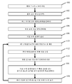
또 다른 실시예에서, 이상 조직을 식별하는 방법은 수술 병상으로 제1 여기 파장을 포함하는 제1 광을 제공하는 단계, 감광 검출기를 사용하여 수술 병상으로부터 형광 신호를 수집하는 단계, 형광 신호를 이상 조직 임계치와 비교함으로써 이상 조직을 식별하는 단계 및 식별된 이상 조직의 하나 이상의 위치를 스크린 상에 표시하는 단계를 포함한다.In yet another embodiment, a method for identifying abnormal tissue comprises providing first light comprising a first excitation wavelength on a surgical bed, collecting a fluorescence signal from a surgical bed using a photodetector, Identifying the abnormal tissue by comparing with the tissue threshold, and displaying on the screen at least one location of the identified abnormal tissue.
다른 실시예에서, 이상 조직을 식별하는 방법은 제1 조명원을 사용하여 이미징 보조제의 제1 여기 파장을 포함하는 제1 광으로 수술 병상을 조명하는 단계와, 제2 조명원을 사용하여 제1 여기 파장과는 다른 제2 파장을 포함하는 제2 광으로 수술 병상을 조명하는 단계와, 감광 검출기를 사용하여 수술 병상으로부터 신호를 수집하는 단계를 포함할 수 있다.In another embodiment, a method for identifying abnormal tissue comprises illuminating a surgical bed with first light comprising a first excitation wavelength of imaging aid using a first illumination source, Illuminating the surgical bed with a second light comprising a second wavelength different from the excitation wavelength, and collecting signals from the surgical bed using a photodetector.
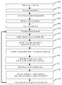
또 다른 실시예에서, 이상 조직을 식별하기 위한 방법은 주변 광으로 수술 병상을 조명하는 단계와, 제1 조명원을 맥동시킴으로써 이미징 보조제의 제1 여기 파장을 포함하는 제1 광으로 수술 병상을 조명하는 단계와, 복수의 화소를 포함하는 감광 검출기를 사용하여 주변 광에 대응하는 수술 병상으로부터의 제1 신호를 수집하는 단계와, 주변 광 및 제1 조명원의 펄스에 대응하는 제2 신호를 수술 병상으로부터 수집하는 단계를 포함할 수 있다.In another embodiment, a method for identifying abnormal tissue comprises illuminating a surgical bed with ambient light, pulsing a first illumination source, and illuminating the surgical bed with a first light comprising a first excitation wavelength of the imaging aid The method comprising the steps of: collecting a first signal from a surgical bed corresponding to ambient light using a photodetector comprising a plurality of pixels; and combining the ambient light and a second signal corresponding to a pulse of the first illumination source, And collecting from the bed.
상술한 개념과 후술된 추가적 개념은 임의의 적절한 조합으로 배열될 수 있으며, 본 내용은 이에 한정되지 않는다는 것을 인지하여야 한다. 또한, 본 내용의 다른 장점 및 신규한 특징은 첨부 도면과 연계하여 고려시 다양한 비제한적 실시예에 대한 이하의 상세한 설명으로부터 명백히 알 수 있을 것이다.It is to be appreciated that the concepts described above and the additional concepts described below may be arranged in any suitable combination, and the subject matter is not so limited. Further, other advantages and novel features of the present invention will become apparent from the following detailed description of various non-limiting embodiments when considered in conjunction with the accompanying drawings.
첨부 도면은 실척대로 그려지기를 의도하는 것은 아니다. 도면에서, 다양한 도면에 예시되어 있는 각각의 동일한 또는 거의 동일한 구성요소는 유사 참조번호로 표시될 수 있다. 명료성의 목적을 위해, 모든 도면에서 모든 구성요소에 도면부호가 부여되어 있는 것은 아니다.
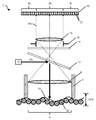
도 1a는 감소된 확대율로 이미징된 수술 병상의 개략도이다.
도 1b는 증가된 확대율로 이미징된 수술 병상의 개략도이다.
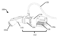
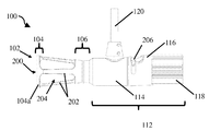
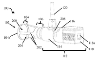
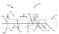
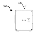
도 2a는 폐쇄 팁 핸드헬드 의료 이미징 장치의 개략적 측면도이다.
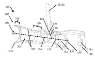
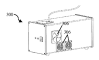
도 2b는 도 2a의 폐쇄 팁 핸드헬드 의료 이미징 장치의 개략적 후방 사시도이다.
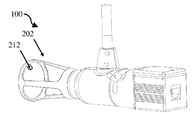
도 2c는 도 2a의 폐쇄 팁 핸드헬드 의료 이미징 장치의 개략적 측면 사시도이다.
도 3a는 도 2a의 폐쇄 팁 핸드헬드 의료 이미징 장치의 단면도이다.
도 3b는 도 2a의 폐쇄 팁 핸드헬드 의료 이미징 장치의 단면 사시도이다.
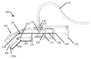
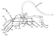
도 4a는 개방 팁 핸드헬드 의료 이미징 장치의 개략 측면도이다.
도 4b는 도 4a의 개방 팁 핸드헬드 의료 이미징 장치의 개략적 후방 사시도이다.
도 4c는 도 4a의 개방 팁 핸드헬드 의료 이미징 장치의 개략적 전방 사시도이다.
도 5a는 도 4a의 개방 팁 핸드헬드 의료 이미징 장치의 개략적 단면도이다.
도 5b는 도 4a의 개방 팁 핸드헬드 의료 이미징 장치의 단면 사시도이다.
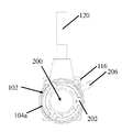
도 6은 유지 요소를 포함하는 강성 이미징 팁의 개략적 후방 사시도이다.
도 7은 배향 특징부를 포함하는 강성 이미징 팁의 개략적 후방 사시도이다.
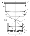
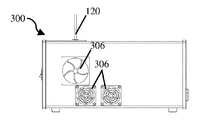
도 8a는 라이트 박스의 개략적 후방 사시도이다.
도 8b는 도 8a의 라이트 박스의 개략적 측면도이다.
도 8c는 도 8a의 라이트 박스의 개략적 사시도이다.
도 8d는 도 8a의 라이트 박스의 개략 단면도이다.
도 9a는 의료 이미징 장치를 동작시키기 위한 방법의 일 실시예의 흐름도이다.
도 9b는 의료 이미징 장치를 동작시키기 위한 방법의 일 실시예의 흐름도이다.
도 9c는 의료 이미징 장치를 동작시키기 위한 방법의 일 실시예의 흐름도이다.
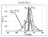
도 10a는 서로 다른 여기 파장을 위한 형광단의 형광 강도의 그래프이다.
도 10b는 서로 다른 여기 파장을 위한 형광단의 형광 강도의 그래프이다.
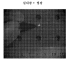
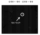
도 11a는 실내 광과 형광 신호에서 취한 이미지이다.
도 11b는 실내 광에서 취한 이미지이다.
도 11c는 실내광과 형광 신호로 취한 이미지로부터 실내광에서 취한 이미지를 차감함으로써 생성된 이미지이다.
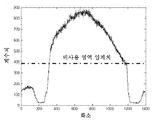
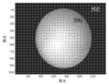
도 12a는 원하는 시계와 시계 외부의 부분을 도시하는 이미징 장치로 포착된 이미지이다.
도 12b는 시계 내의 그리고 시계 외부의 화소의 광자 계수치(counts)를 도시하는 그래프이다.
도 12c는 원하는 값으로 설정된 시계 외부의 화소를 갖는 이미지이다.
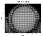
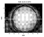
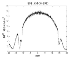
도 13a는 초점 내에 있는 동안 형광투시 표준의 이미지이다.
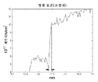
도 13b는 초점 외부에 있는 동안 형광투시 표준의 이미지이다.
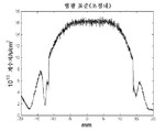
도 14a는 초점내 이미지에 대응하는 도 13a를 가로질러 취한 선을 위한 광자 계수치의 그래프이다.
도 14b는 초점외 이미지에 대응하는 도 13b를 가로질러 취한 선을 위한 광자 계수치의 그래프이다.
도 15a는 초점내 이미지에 대응하는 도 14a에 도시된 그래프의 일부의 확대도이다.
도 15b는 초점외 이미지에 대응하는 도 14b에 표시된 그래프의 일부의 확대도이다.
도 16a는 LUM015가 주입된, 자연적으로 폐암이 발생한 개로부터의 종양의 이미지이다.
도 16b는 자연적으로 폐암이 발생한 개로부터의 정상적 폐 조직의 이미지이다.
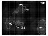
도 17a는 LUM015의 IV 주입에 후속하여 쥐에서의 수술 이후 쥐 육종 수술 병상의 LUM015를 사용하여 취한 원 이미지이다.
도 17b는 잔류 암을 포함하는 영역을 하이라이팅하기 위해 검출 시스템에 의해 분석된 도 17a와 동일한 이미지이다.
도 17c는 잔류 암을 포함하는 영역을 하이라이팅하기 위해 검출 시스템에 의해 분석된 도 17a와 동일한 이미지이다.
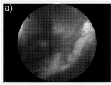
도 18a는 수술 병상의 원 이미지이다.
도 18b는 이상 조직을 포함하는 영역을 하이라이팅하기 위해 검출 시스템에 의해 분석된 도 18a와 동일한 이미지이다.
도 19는 수술 병상 내의 이상 조직을 포함하는 영역을 하이라이팅하는 이미지를 제공하기 위해 사용될 수 있는 인터페이스의 예시적 스크린샷이다.The accompanying drawings are not intended to be drawn to scale. In the drawings, each identical or substantially identical component illustrated in the various figures may be represented by like reference numerals. For purposes of clarity, not all elements are numbered in all figures.
1A is a schematic view of a surgical bed imaged at a reduced magnification.
1B is a schematic view of a surgical bed imaged at an increased magnification.
2A is a schematic side view of a closed tip handheld medical imaging device.
Figure 2B is a schematic rear perspective view of the closed-tip handheld medical imaging device of Figure 2A.
2C is a schematic side perspective view of the closed tip handheld medical imaging device of FIG. 2A.
Figure 3a is a cross-sectional view of the closed-tip handheld medical imaging device of Figure 2a.
3B is a cross-sectional perspective view of the closed tip handheld medical imaging device of FIG. 2A.
4A is a schematic side view of an open tip handheld medical imaging device.
4B is a schematic rear perspective view of the open-tipped handheld medical imaging device of FIG. 4A.
4C is a schematic front perspective view of the open-tipped handheld medical imaging device of FIG. 4A.
5A is a schematic cross-sectional view of the open-tipped handheld medical imaging device of FIG. 4A.
Figure 5b is a cross-sectional perspective view of the open-tipped handheld medical imaging device of Figure 4a.
Figure 6 is a schematic rear perspective view of a rigid imaging tip including a retaining element.
Figure 7 is a schematic rear perspective view of a rigid imaging tip including an orientation feature.
8A is a schematic rear perspective view of the light box.
Figure 8b is a schematic side view of the light box of Figure 8a.
Figure 8c is a schematic perspective view of the light box of Figure 8a.
FIG. 8D is a schematic cross-sectional view of the light box of FIG. 8A. FIG.
9A is a flow diagram of one embodiment of a method for operating a medical imaging device.
9B is a flow diagram of one embodiment of a method for operating a medical imaging device.
9C is a flow diagram of one embodiment of a method for operating a medical imaging device.
FIG. 10A is a graph of the fluorescence intensity of the fluorescent end for different excitation wavelengths. FIG.
Fig. 10B is a graph of the fluorescence intensity of the fluorescent end for different excitation wavelengths.
11A is an image taken from the indoor light and the fluorescent signal.
11B is an image taken from room light.
11C is an image generated by subtracting the image taken from the room light from the image taken with the indoor light and the fluorescent signal.
12A is an image captured by an imaging device showing a desired clock and a portion outside the clock.
12B is a graph showing the photon count values (counts) of the pixels in the clock and outside the clock.
12C is an image having a pixel outside the clock set to a desired value.
13A is an image of a fluoroscopy standard while in focus.
Figure 13b is an image of the fluoroscopy standard while out of focus.
14A is a graph of photon count values for a line taken across FIG. 13A corresponding to an in-focus image. FIG.
14B is a graph of photon count values for a line taken across FIG. 13B corresponding to an out-of-focus image.
15A is an enlarged view of a portion of the graph shown in FIG. 14A corresponding to an in-focus image.
Fig. 15B is an enlarged view of a part of the graph shown in Fig. 14B corresponding to an out-of-focus image.
16A is an image of a tumor from a dog in which LUM015 is injected, naturally occurring in lung cancer.
16B is an image of normal lung tissue from a dog naturally occurring in a lung cancer.
17A is an original image taken following LUMO15 IV injection with post-operative surgery in mice using LUMO15 in a mouse sarcoma surgical bed.
FIG. 17B is the same image as FIG. 17A analyzed by the detection system to highlight areas containing residual arms.
Figure 17C is the same image as Figure 17A analyzed by the detection system to highlight areas containing residual arms.
18A is an original image of a surgical bed.
FIG. 18B is the same image as FIG. 18A analyzed by the detection system to highlight areas containing abnormal tissue.
19 is an exemplary screenshot of an interface that may be used to provide an image highlighting a region containing abnormal tissue within a surgical wound bed.
본 발명자는 암 타겟 분자 이미징 보조제의 진보가 건강한 조직의 배경 상에 잔류 암의 작은 클러스터의 검출을 가능하게 하였다는 것을 인지하여 왔다. 그러나, 밀리미터 내지 서브밀리미터 규모의 암 조직을 시각적으로 수술 동안 식별하는 것은 이들 이미징 보조제를 사용하더라도 어렵다. 따라서, 본 발명자는 이러한 암 조직의 제거를 돕기 위해 수술 동안 밀리미터 내지 서브밀리미터 잔류 암 세포를 신뢰성있게 검출할 수 있는 의료 이미징 장치에 대한 필요성을 인식하여 왔다. 이런 이미징 장치는 수술 병상에 남겨진 암 조직에 기인하여 요구되는 후속 수술의 수를 감소시키는 것을 도울 수 있다.The inventors have recognized that the advancement of cancer target molecule imaging adjuvants has enabled the detection of small clusters of residual cancer on the background of healthy tissue. However, it is difficult to visually identify the cancer tissue of the millimeter to sub-millimeter scale during surgery even using these imaging adjuvants. Therefore, the inventors have recognized the need for a medical imaging device that can reliably detect millimeter to sub-millimeter residual cancer cells during surgery to aid in the removal of such cancerous tissue. Such an imaging device can help reduce the number of subsequent surgeries required due to cancer tissue remaining in the surgical bed.
상술한 견지에서, 본 발명자는 적절한 이미징 보조제와 함께 사용하기 위한 핸드헬드 의료 이미징 장치와 연계된 이득을 인식하여 왔다. 일부 실시예에서, 의료 이미징 장치는 이미징 장치의 조명 노이즈를 초과하는 이미징 보조제로부터의 형광 신호를 발생시키도록 이미징 보조제의 여기 파장의 충분한 조명을 제공할 수 있다. 일부 실시예에서, 의료 이미징 장치에 의해 제공된 조명은 또한 건강한 조직으로부터의 자동형광 신호를 초래할 수 있다. 의료 이미징 장치는 또한 수 센티미터로부터 10 마이크로미터 내지 수십 마이크로미터 정도의 크기를 갖는 단일 세포까지의 범위의 크기의 이상 조직을 검출할 수 있다. 다른 크기 규모도 가능하다. 더 상세히 후술된 바와 같이, 일부 실시예에서, 실시간으로 큰 시계를 이미징할 수 있으며, 및/또는 핸드헬드 장치에 고유한 인간 운동과 유방암 및 폐암 수술 같은 특정 수술 유형에 수반되는 환자의 자연적 운동에 비교적 둔감하게 되는 것이 의료 이미징 장치에 바람직할 수 있다. 본 내용은 이에 한정되지 않으므로, 이미징 장치는 종양 병상 같은 수술 병상을 이미징하기 위해 사용되거나 이미 절제된 조직의 이미징을 위해 사용될 수 있다.In view of the foregoing, the inventor has recognized the benefits associated with handheld medical imaging devices for use with appropriate imaging aids. In some embodiments, the medical imaging device may provide sufficient illumination of the excitation wavelength of the imaging aid to generate a fluorescence signal from the imaging aid that exceeds the illumination noise of the imaging device. In some embodiments, the illumination provided by the medical imaging device may also result in automatic fluorescent signals from healthy tissue. Medical imaging devices can also detect abnormal tissue of a size ranging from a few centimeters to a single cell with a size of the order of 10 micrometers to tens of micrometers. Other sizes are also possible. As will be described in more detail below, in some embodiments, a large clock can be imaged in real time and / or the human motion inherent in the handheld device and the natural movement of the patient following certain surgical types such as breast and lung cancer surgery It may be desirable for a medical imaging device to be relatively insensitive. The present disclosure is not so limited, and thus the imaging device may be used for imaging a surgical bed, such as a tumor bed, or may be used for imaging of already ablated tissue.
일 실시예에서, 의료 이미징 장치는 광학적으로 연계된 감광 검출기로부터 고정된 거리에 초점 평면을 형성하는 원위 단부를 포함하는 강성 이미징 팁을 포함할 수 있다. 예로서, 원위방향 연장 부재는 감광 검출기의 초점 평면을 그 원위 단부에서 형성할 수 있다. 실시예에 따라서, 감광 검출기와 연계된 광학계는 강성 이미징 팁의 원위 단부에 위치된 초점 평면에서 감광 검출기의 초점을 고정하거나 강성 이미징 팁의 원위 단부를 초과하여 위치된 다른 초점 평면과 이미징 팁의 원위 단부에 위치된 초점 평면 사이에서 감광 검출기의 초점이 이동될 수 있게 할 수 있다. 임의의 적절한 감광 검출기가 사용될 수 있지만, 예시적 감광 검출기는 전하 결합 장치(CCD) 검출기, 상보적 금속 산화물 반도체(CMOS) 검출기 및 전자사태 광 다이오드(APD)를 포함한다. 감광 검출기는 강성 이미징 팁의 초점 평면으로부터 감광 검출기로 광학 축이 지나가도록 복수의 화소를 포함할 수 있다.In one embodiment, the medical imaging device may include a rigid imaging tip including a distal end forming a focal plane at a fixed distance from the optically coupled photodetector. By way of example, the distal extending member may form a focal plane of the photodetector at its distal end. Depending on the embodiment, the optical system associated with the photodetector detector may fix the focus of the photodetector detector at a focal plane located at the distal end of the rigid imaging tip, or at a distal of the imaging tip relative to another focal plane positioned beyond the distal end of the rigid imaging tip So that the focus of the photodetector detector can be shifted between the focus planes positioned at the ends. Exemplary photosensor detectors include a charge coupled device (CCD) detector, a complementary metal oxide semiconductor (CMOS) detector, and an electronic scene photodiode (APD), although any suitable photosensor may be used. The photodetector detector may include a plurality of pixels such that the optical axis passes from the focal plane of the rigid imaging tip to the photodetector.
실시예에 따라서, 의료 이미징 장치는 또한 이미징 보조제의 방출 파장을 포함하는 방출 광이 감광 다이오드로 전달될 수 있게 하면서, 이미징 보조제의 여기 파장을 포함하는 조명원으로부터의 광을 장치의 원위 단부를 향해 선택적으로 지향시키기 위한 하나 이상의 광 지향 요소를 포함할 수 있다. 일 양태에서, 발광 요소는 파장 컷오프를 초과하는 파장을 갖는 이미징 보조제에 의해 방출된 광을 감광 검출기로 전달될 수 있게 하면서, 연계된 이미징 팁의 원위 단부를 향해 파장 컷오프 미만의 광을 반사하도록 위치된 이색성 거울을 포함한다. 그러나, 예로서, 광섬유, 강성 팁 내에 위치된 LED 및 다른 적절한 구성을 포함하는 장치의 원위 단부를 향해 광을 지향시키는 다른 방식이 사용될 수 있다는 것을 이해하여야 한다.According to an embodiment, the medical imaging device may also be configured to direct light from an illumination source including the excitation wavelength of the imaging aid to the distal end of the device, while allowing emission light comprising the emission wavelength of the imaging aid to be transmitted to the photodiode And may include one or more light directing elements for selectively directing light. In one aspect, the light emitting element is positioned to reflect light less than the wavelength cutoff toward the distal end of the associated imaging tip, while allowing light emitted by the imaging aid having a wavelength greater than the wavelength cutoff to be transmitted to the photo detector ≪ / RTI > It should be understood, however, that other ways of directing light toward the distal end of the device, including, for example, optical fibers, LEDs positioned within the rigid tip, and other suitable configurations, can be used.
또한, 이미징 장치는 원하는 해상도를 갖는 감광 검출기 상으로 장치의 시계 내부로부터 방출된 광을 집속시키도록 적절한 광학계를 포함할 수 있다. 원하는 해상도를 제공하기 위해, 광학계는 복수의 화소를 포함하는 감광 검출기 상으로 임의의 적절한 확대율을 사용하여 방출된 광을 집속시킬 수 있다. 일부 실시예에서, 확대율은 각 화소가 단일 세포의 단지 일부 또는 단일 세포에 대응하는 시계를 갖도록 이루어진다. 본 내용은 이에 한정되지 않으므로, 개별 화소의 크기에 따라서, 광학계는 확대율, 축소율 중 어느 하나를 제공하거나 어떠한 확대율도 제공하지 않을 수 있다. 예로서, 감광 검출기의 화소가 이미징되는 세포보다 작은 실시예에서, 광학계는 예로서, 세포 당 4개 화소 같이 각 화소의 원하는 시계를 제공하도록 장치의 시계를 축소할 수 있다. 각 화소의 시계가 단일 세포 이하인 실시예가 상술되었지만, 각 화소의 시계가 단일 세포보다 큰 실시예도 고려된다.The imaging device may also include a suitable optical system to focus the light emitted from the interior of the device's clock onto a photosensor with the desired resolution. To provide the desired resolution, the optical system may focus the emitted light using any suitable magnification onto the photodetector including a plurality of pixels. In some embodiments, the magnification is such that each pixel has a clock corresponding to only a portion of a single cell or a single cell. The present invention is not limited to this, and depending on the size of the individual pixels, the optical system may provide either the enlargement ratio or the reduction ratio or may not provide any enlargement ratio. By way of example, in embodiments where the pixels of the photodetector are smaller than the cell being imaged, the optical system may shrink the device's clock to provide the desired clock for each pixel, for example, four pixels per cell. Although an embodiment in which the clock of each pixel is equal to or less than a single cell is described above, embodiments in which the clock of each pixel is larger than a single cell are also considered.
이론에 구속되지 않고, 통상적 암 세포는 약 15 ㎛ 지름 정도일 수 있다. 상술한 견지에서, 의료 이미징 장치 내의 광학계의 광학 확대율은 각 화소의 시계가 약 1 ㎛, 2 ㎛, 3 ㎛, 4 ㎛, 5 ㎛, 10 ㎛, 15 ㎛, 30 ㎛ 또는 임의의 다른 원하는 값 이상일 수 있도록 선택될 수 있다. 추가적으로, 각 화소의 시계는 약 100 ㎛, 50 ㎛, 40 ㎛, 30 ㎛, 20 ㎛, 10 ㎛ 또는 임의의 다른 원하는 크기 규모 미만일 수 있다. 다른 특정 실시예에서, 화소 당 시계는 약 5 ㎛과 100 ㎛ 사이(경계값 포함)일 수 있다. 다른 실시예에서, 화소당 시계는 약 5 ㎛과 50 ㎛ 사이(경계값 포함)일 수 있다.Without being bound by theory, conventional cancer cells can be on the order of about 15 microns in diameter. In view of the foregoing, the optical magnification of the optical system in the medical imaging device may be such that the clock of each pixel is at least about 1, 2, 3, 4, 5, 10, 15, 30 or any other desired value Lt; / RTI > Additionally, the clock of each pixel may be less than about 100, 50, 40, 30, 20, 10 or any other desired size scale. In another particular embodiment, the per-pixel clock may be between about 5 [mu] m and 100 [mu] m (inclusive). In other embodiments, the per-pixel clock may be between about 5 [mu] m and 50 [mu] m (inclusive).
일부 경우에, 이상 조직의 작은 영역 및 이상 조직의 큰 영역 양자 모두를 식별하는 것이 바람직할 수 있다. 이는 특히, 수술 공동이 20 cm 직경을 가질 수 있는 난소암 수술 같은 수술에서 유익할 수 있다. 따라서, 일 실시예에서, 이미징 장치 내에 존재하는 광학계는 마이크로미터 규모 이상 조직을 검출하기 위해 사용되는 고 확대율 설정과 의료 이미징 장치가 수술 공동의 큰 부분을 관찰하기 위해 스탠드오프 모드로 사용될 수 있는 저 확대율 설정 사이에서 감광 검출기에 의해 포획된 방출 광의 확대율을 변경하기 위해 사용될 수 있다. 실시예에 따라서, 감광 검출기의 화소의 시계는 약 5 ㎛과 100 ㎛ 사이에서 선택적으로 설정될 수 있다. 의료 이미징이 연계된 감광 검출기로부터 고정된 거리에 고정된 초점 평면을 형성하는 강성 이미징 팁을 포함하는 경우에, 상술한 실시예는 고정된 초점 평면으로부터 강성 이미징 팁의 원위 단부를 초과하여 제2 거리에 위치된 제2 초점 평면으로 감광 검출기의 초점을 이동시켜 의료 이미징 장치의 단부를 초과하여 위치된 조직을 이미징하기 위해 스탠드오프 모드에서의 장치의 사용을 가능하게 하는 것에 대응할 수 있다. 이 제2 초점 평면은 적절한 집속 요소를 사용하여 가변적으로 설정될 수 있거나 고정된 거리에 위치될 수 있다. 또한, 의료 이미징 장치의 초점은 자동으로 제어될 수 있거나 본 내용이 이에 한정되지 않으므로 수동으로 제어될 수 있다.In some cases, it may be desirable to identify both a small region of abnormal tissue and a large region of abnormal tissue. This can be particularly beneficial in surgery such as ovarian cancer surgery where the surgical cavity can have a diameter of 20 cm. Thus, in one embodiment, the optical system present in the imaging device is configured to have a high magnification setting that is used to detect micrometer-scale or more tissue and a high magnification setting that allows the medical imaging device to be used in a stand-off mode to observe a large portion of the surgical cavity. May be used to change the magnification of the emitted light captured by the photodetector between the magnification setting. Depending on the embodiment, the clock of the pixel of the photodetector can be selectively set between about 5 [mu] m and 100 [mu] m. In the case where the medical imaging includes a rigid imaging tip that forms a fixed focal plane at a fixed distance from the associated photodetector detector, the embodiment described above may be used to determine a second distance To enable the use of the device in the stand-off mode to image the tissue positioned beyond the end of the medical imaging device by moving the focus of the photodetector detector to a second focus plane located at the end of the medical imaging device. This second focal plane may be variably set using an appropriate focusing element or may be located at a fixed distance. In addition, the focus of the medical imaging device may be controlled automatically or may be manually controlled since the present disclosure is not so limited.
상술한 바와 같이, 수술 동안 환자의 자연적 운동에 대한 의료 이미징 장치의 민감도를 감소시키고 해상도를 향상시키는 것이 바람직할 수 있다. 이는 환자의 자연적 운동이 이미징과 간섭할 수 있는 유방 종양절제 및 폐암 수술 같은 수술에 특히 유익할 수 있다. 이론에 구속되지 않고, 환자의 자연적 운동에 대한 민감도를 감소시키고 해상도를 개선시키는 한가지 방식은 해당 조직으로부터 신호를 포착하기 위해 사용되는 감광 검출기와 검사 대상 조직 사이의 거리를 고정시키는 것이다. 따라서, 실시예에서, 의료 이미징 장치는 검사되는 조직과 감광 검출기 사이에서 고정된 거리를 제공하도록 구성 및 배열될 수 있다. 이는 예로서, 강성 이미징 팁을 검사되는 조직과 접촉하는 상태로 배치되게 구성하는 것을 포함하는 임의의 수의 방식으로 제공될 수 있다. 이미징 팁은 그 형상을 유지하면서 조직에 대해 가압되도록 충분히 강성적일 수 있다. 따라서, 강성적 이미징 팁은 감광 검출기와 조직 사이에 고정된 거리를 제공하도록 스페이서로서 작용할 수 있다. 추가적으로, 강성 이미징 팁이 검사되는 조직에 대해 가압될 수 있기 때문에, 이는 환자 이동에 기인한 조직의 측방향 및 평면외 이동 양자 모두를 저지할 수 있다.As noted above, it may be desirable to reduce the sensitivity of the medical imaging device to natural movement of the patient during surgery and to improve resolution. This may be particularly beneficial for surgery, such as breast tumor resection and lung cancer surgery, where the patient's natural motion may interfere with imaging. Without being bound by theory, one way to reduce the patient's sensitivity to natural motion and improve resolution is to fix the distance between the photosensor and tissue to be examined used to capture signals from the tissue. Thus, in an embodiment, the medical imaging device can be configured and arranged to provide a fixed distance between the tissue being examined and the photodetector. This may be provided in any number of ways, including, for example, configuring the rigid imaging tip to be placed in contact with the tissue being examined. The imaging tip may be sufficiently rigid to press against the tissue while maintaining its shape. Thus, the rigid imaging tip can act as a spacer to provide a fixed distance between the photodetector and the tissue. Additionally, because the rigid imaging tip can be pressed against the tissue being examined, it can block both lateral and out-of-plane movement of the tissue due to patient movement.
일 실시예에서, 강성 이미징 팁은 폐쇄형 이미징 팁에 대응할 수 있다. 이런 실시예에서, 강성 이미징 팁의 원위 단부는 실질적으로 평탄한 윈도우일 수 있으며, 그래서, 이는 연계된 감광 검출기의 초점 평면을 형성한다. 이론에 구속되지 않고, 원위 단부의 평탄한 표면이 이미징되는 조직에 대해 가압될 때, 조직은 폐쇄형 이미징 팁의 형상에 합치되도록 압축될 수 있다. 이는 순차적으로 감광 검출기의 초점 평면에 인접한 조직을 감광 검출기와 검사 되는 조직 사이에 고정된 거리를 제공하도록 위치시킬 수 있다. 일 특정 실시예에서, 평탄한 원위 단부는 강성 이미징 팁의 원위 단부 상에 배치되거나 그에 통합된 평탄한 윈도우에 대응할 수 있다. 윈도우는 원하는 이미징 보조제의 방출 파장 및 여기 파장 같은 하나 이상의 사전선택된 파장 또는 파장의 스펙트럼에 대해 투과성일 수 있다. 따라서, 조직은 이미징 보조제의 여기 파장 및/또는 방출 파장을 포함하는 광이 이미징 장치 밖으로, 그리고, 다시, 이미징 장치 내부로 통과할 수 있게 하면서 원하는 초점 평면 내에 또는 그에 근접 인접하게 위치될 수 있다. 다른 실시예에서, 이미징 팁의원위 단부는 원형 개구를 형성하는 링일 수 있으며, 다른 형상을 통한 초점 평면도 마찬가지로 사용될 수 있다.In one embodiment, the rigid imaging tip may correspond to a closed imaging tip. In this embodiment, the distal end of the rigid imaging tip may be a substantially flat window, so that it forms the focal plane of the associated photodetector. Without being bound by theory, when the flat surface of the distal end is pressed against the tissue to be imaged, the tissue can be compressed to conform to the shape of the occlusion imaging tip. Which in turn can position the tissue adjacent the focal plane of the photodetector detector to provide a fixed distance between the photodetector and the tissue being examined. In one particular embodiment, the flat distal end may correspond to a flat window disposed on or integral with the distal end of the rigid imaging tip. The window may be transmissive to the spectrum of one or more preselected wavelengths or wavelengths, such as the emission wavelength and the excitation wavelength of the desired imaging aid. Thus, the tissue can be positioned within or close to a desired focal plane, allowing light, including excitation and / or emission wavelengths of imaging aids, to pass out of the imaging device and again into the imaging device. In another embodiment, the upper end of the imaging tip may be a ring forming a circular opening, and a focus plane through other features may be used as well.
수술 공동 내로의 강성 이미징 팁의 삽입을 돕기 위해, 일부 실시예에서, 핸드헬드 장치의 본체에 대해 또는 강성 이미징 팁의 근위 부분에 대해 각진 원위 부분을 강성 이미징 팁이 포함하는 것이 바람직할 수 있다. 장치의 광학 경로는 강성 이미징 팁의 원위 단부로부터 강성 이미징 팁의 원위 및 근위 부분 양자 모두를 통해 광학적으로 연계된 감광 검출기로 통과할 수 있다. 각진 원위 및 근위 부분 둘레에서 광학 경로를 굴곡시키기 위해, 강성 이미징 팁은, 강성 이미징 팁의 각진 부분 주변에서 광학 경로를 굴곡시키도록 구성된 거울 또는 프리즘 같은, 강성 이미징 팁의 근위 부분과 원위 부분 사이에 위치된 적절한 광학 구성요소를 포함할 수 있다. 일 특정 양태에서, 강성 이미징 팁은 약 10 mm 내지 50 mm(경계값 포함), 15 mm 내지 35 mm(경계값 포함), 25 mm 내지 35 mm(경계값 포함) 또는 임의의 다른 적절한 치수 범위의 측방향 치수를 갖는 초점 영역을 형성하는 원위 단부를 가질 수 있다. 팁의 원위 부분은 또한 약 25° 내지 65° 사이(경계값 포함)의 각도, 35° 내지 55° 사이의(경계값 포함) 각도 또는 임의의 다른 적절한 각도 만큼 근위 부분에 대해 각질 수 있다. 추가적으로, 강성 이미징 팁은 약 10 mm 내지 65 mm(경계값 포함), 25 mm 내지 65 mm(경계값 포함), 또는 임의의 다른 적절한 길이일 수 있는 광학 경로를 따른 길이를 가질 수 있다. 이런 실시예는 특히 유방 수술에 적합할 수 있으며, 여기서, 장치는 수술 병상에 대해 초점 평면을 용이하게 위치설정하도록 손으로 회전될 수 있다.To assist in the insertion of a rigid imaging tip into the surgical cavity, in some embodiments, it may be desirable for the rigid imaging tip to include an angled distal portion relative to the body of the handheld device or relative to the proximal portion of the rigid imaging tip. The optical path of the device may pass from the distal end of the rigid imaging tip to both of the distal and proximal portions of the rigid imaging tip and to the optically coupled photodetector. To bend the optical path around the angled distal and proximal portions, the rigid imaging tip is positioned between a proximal portion and a distal portion of the rigid imaging tip, such as a mirror or prism, configured to bend the optical path around the angled portion of the rigid imaging tip And may include suitable optical components located therein. In one particular embodiment, the rigid imaging tip has a thickness ranging from about 10 mm to 50 mm (inclusive), from 15 mm to 35 mm (inclusive), from 25 mm to 35 mm (inclusive), or any other suitable range of dimensions And may have a distal end forming a focal region having a lateral dimension. The distal portion of the tip may also be angled relative to the proximal portion by an angle between about 25 ° and 65 ° (inclusive), between 35 ° and 55 ° (inclusive) or any other suitable angle. Additionally, the rigid imaging tip may have a length along an optical path that may be between about 10 mm and 65 mm (inclusive), between 25 mm and 65 mm (inclusive), or any other suitable length. Such an embodiment may be particularly suited to breast surgery, wherein the device can be rotated by hand to easily position the focal plane relative to the surgical bed.
다른 실시예에서, 수술 병상의 이미징 및 동시적 수술적 접근을 용이하게 하는 것이 바람직할 수 있다. 한 가지 이런 실시예에서, 강성 이미징 팁은 사용 동안 조직에 인접하게 위치되도록 구성되는 초점 평면을 형성하는 개구를 포함하는 원위 단부를 포함할 수 있다. 또한, 이미징 팁은 강성 이미징 팁의 원위 단부의 개구에 대한 접근로를 제공하도록 강성 이미징 팁의 측부 상에 위치된 하나 이상의 개구를 포함할 수 있다. 이미징 팁의 측부 상의 하나 이상의 개구는 강성 이미징 팁의 측벽에 형성되거나, 강성 이미징 팁의 근위 부분으로부터 강성 이미징 팁의 원위 조직 결합 부분으로 연장하는 하나 이상의 지지부 사이에 형성될 수 있다. 일 실시예에서, 초점 평면을 형성하는 원위 링은 단일 스트러트에 의해 지지되고, 링에 의해 형성되는 개구는 단일 스트러트에 의해서만 막혀지고 임의의 측면에서 접근가능하다. 이런 경우에, 의사는 강성 이미징 팁의 시계 내에 위치된 이상 조직을 이미징하고 동시에 강성 이미징 팁의 하나 이상의 측부 개구와 개방 원위 단부를 통해 식별된 이상 조직에 대한 수술을 수행할 수 있는 양자 모두가 가능하다.In other embodiments, it may be desirable to facilitate imaging and simultaneous surgical access of the surgical beds. In one such embodiment, the rigid imaging tip may include a distal end comprising an aperture defining a focal plane configured to be positioned adjacent to the tissue during use. The imaging tip may also include one or more apertures located on the sides of the rigid imaging tip to provide an access path to the opening at the distal end of the rigid imaging tip. One or more openings on the side of the imaging tip may be formed in the side wall of the rigid imaging tip or may be formed between one or more supports extending from the proximal portion of the rigid imaging tip to the distal tissue-engaging portion of the rigid imaging tip. In one embodiment, the distal ring forming the focal plane is supported by a single strut, and the opening formed by the ring is clogged only by a single strut and accessible from any side. In this case, the physician is able to both image the abnormal tissue located within the watch of the rigid imaging tip, and simultaneously perform surgery on the identified abnormal tissue through one or more side openings and an open distal end of the rigid imaging tip Do.
일 실시예에서, 의료 이미징 장치는 하나 이상의 조명원과 연계 및/또는 결합될 수 있다. 예로서, 제1 조명원은 강성 이미징 팁의 원위 단부를 향해 임계치 파장 미만의 광을 반사하고 임계치 파장을 초과한 광을 전송하는 광 지향 요소에 제1 파장을 포함하는 광을 제공하도록 구성 및 배열될 수 있다. 그러나, 하나 이상의 조명원으로부터의 광을 광섬유를 포함하는 강성 이미징 팁의 원위 단부를 향해 지향하는 다른 방식 및 장치 또는 강성 이미징 팁 내에 위치된 LED도 사용될 수 있다. 광이 지향되는 방식에 무관하게, 제1 파장은 임계치 파장 미만이도록, 그리고, 따라서, 장치의 시계를 조명하기 위해 강성 이미징 팁의 원위 단부를 향해 반사되도록 선택될 수 있다. 조명원은 특정 실시예에 따라서 일정한 조명원 또는 맥동 조명원일 수 있다. 추가적으로, 제1 파장은 원하는 이미징 보조제의 여기 파장에 대응하도록 선택될 수 있다. 특정 파장은 사용되는 특정 이미징 보조제, 광학계 및 감광 검출기의 감도에 의존할 것이다. 그러나, 일부 실시예에서, 제1 파장은 약 300 nm 내지 1,000 nm, 590 nm 내지 680 nm, 600 nm 내지 650 nm, 620 nm 내지 640 nm 또는 사용되는 특정 이미징 보조제에 따른 임의의 다른 적절한 범위의 파장일 수 있다. 추가적으로, 다른 조명원 강도도 사용될 수 있지만, 제1 조명원은 수술 병상 내의 조직을 이미징하기 위해 원하는 초점 평면에서 약 10 mW/cm2 내지 200 mW/cm2 사이를 제공하도록 구성될 수 있다. 예로서, 50 mW/cm2 내지 200 mW/cm2, 100 mW/cm2 내지 200 mW/cm2, 150 mW/cm2 내지 200 mW/cm2 의 광 강도도 사용될 수 있다. 사용되는 특정 이미징 보조제에 따라서, 의료 이미징 장치의 다양한 구성요소는 또한 약 300 nm 내지 1,000 nm, 590 nm 내지 680 nm, 600 nm 내지 650 nm, 620 nm 내지 640 nm 또는 임의의 다른 적절한 파장 범위인 이미징 보조제로부터의 방출 파장을 수집하도록 구성 및 배열될 수 있다.In one embodiment, the medical imaging device may be associated with and / or coupled to one or more illumination sources. By way of example, a first illumination source may be configured and arranged to provide light having a first wavelength in a light directing element that reflects less than a threshold wavelength of light toward a distal end of the rigid imaging tip and transmits light exceeding a threshold wavelength . However, other approaches and arrangements for directing light from one or more illumination sources towards the distal end of a rigid imaging tip comprising an optical fiber, or an LED positioned within a rigid imaging tip, may also be used. Regardless of the manner in which the light is directed, the first wavelength may be selected to be below the threshold wavelength, and thus be reflected towards the distal end of the rigid imaging tip to illuminate the watch of the device. The illumination source may be a constant illumination source or a pulsation illumination source, depending on the particular embodiment. Additionally, the first wavelength may be selected to correspond to the excitation wavelength of the desired imaging aid. The specific wavelength will depend on the sensitivity of the specific imaging adjuvant, optical system and photodetector used. However, in some embodiments, the first wavelength may range from about 300 nm to 1,000 nm, from 590 nm to 680 nm, from 600 nm to 650 nm, from 620 nm to 640 nm, or any other suitable range of wavelengths Lt; / RTI > Additionally, other illumination source intensities may be used, but the first illumination source may be configured to provide between about 10 mW / cm 2 and 200 mW / cm 2 at a desired focal plane for imaging tissue within the surgical bed. As an example, a concentration of 50 mW / cm 2 to 200 mW / cm 2 , 100 mW / cm 2 to 200 mW / cm 2 , 150 mW / cm 2 to 200 mW / cm 2 May also be used. Depending on the particular imaging adjuvant used, the various components of the medical imaging device may also be imaged at a resolution of about 300 nm to 1,000 nm, 590 nm to 680 nm, 600 nm to 650 nm, 620 nm to 640 nm, And can be configured and arranged to collect emission wavelengths from the adjuvant.
구면 수차를 감소시키고 이미지의 시계 깊이를 향상시키는 것을 돕기 위해, 의료 이미징 장치는 적절한 크기의 애퍼쳐를 포함할 수 있다. 그러나, 더 작은 애퍼쳐는 대응적으로 더 낮은 신호가 연계된 감광 검출기에 도달하게 한다. 따라서, 이미징 보조제의 신호 크기 대 주변 정상 조직의 자동형광 신호와 감광 검출기 접지 및 다크 노이즈에 의존하여, 연계된 조명원에 의해 제공되는 조명을 증가시킬 필요가 있을 수 있다. 일 실시예에서, 조명원과 애퍼쳐 크기의 적절한 조합은 상술한 조명원과, 약 1.5 내지 4.5 사이의(경계값 포함) 이미지측 f 수를 제공하도록 약 5 mm 내지 15 mm 사이의(경계값 포함) 직경을 갖는 강성 이미징 팁과 감광 검출기 사이에 위치된 애퍼쳐를 포함한다. 관련 실시예에서, 애퍼쳐는 약 3 내지 3.5 사이의(경계값 포함) f 수를 제공하도록 크기설정될 수 있다.To help reduce spherical aberration and improve the depth of vision of the image, the medical imaging device may include apertures of appropriate size. However, a smaller aperture allows correspondingly lower signals to reach the associated dimmer detector. Thus, it may be necessary to increase the illumination provided by the associated illumination source, depending on the signal size of the imaging aid versus the auto-fluorescence signal of the surrounding normal tissue and the photodetector ground and dark noise. In one embodiment, a suitable combination of illumination source and aperture size may be selected from the above-described illumination source and an illumination source of between about 5 mm and 15 mm to provide an image-side f-number of between about 1.5 and 4.5 And includes apertures positioned between the rigid imaging tip and the photodetector. In a related embodiment, the aperture may be sized to provide an f-number between about 3 and 3.5 (inclusive).
일 특정 실시예에서, 이미징 장치는 약 3.4의 이미지측 f수에 대응하는 약 10.6 mm 폭을 갖는 애퍼쳐를 포함한다. 이미징 장치는 또한 630 nm에서 약 5W의 광을 방출하도록 구성된 50 W 적색 LED를 포함하는 광원을 포함한다. 이러한 실시예에서, 수술 병상에 입사되는 광은 약 60 mW/cm2이다. 연계된 광 지향 요소는 이색성 거울이며, 약 660 nm의 파장 컷오프를 갖고 이미징 장치의 원위 단부를 향해 컷오프 임계치 미만의 파장을 갖는 광을 반사한다. 특정 애퍼쳐, 컷오프 임계치 및 조명원이 상술되었지만, 다른 범위의 애퍼쳐 크기, f 수, 파장 및 컷오프 임계치도 전술된 바와 같이 고려된다는 것을 이해하여야 한다.In one particular embodiment, the imaging device comprises an aperture having a width of about 10.6 mm corresponding to an image side f number of about 3.4. The imaging device also includes a light source that includes a 50 W red LED configured to emit about 5 W of light at 630 nm. In this embodiment, the light incident on the surgical bed is about 60 mW / cm 2 . The associated light directing element is a dichroic mirror and has a wavelength cutoff of about 660 nm and reflects light having a wavelength less than the cutoff threshold towards the distal end of the imaging device. While particular apertures, cut-off thresholds and illumination sources have been described above, it should be understood that other ranges of aperture size, f-number, wavelength, and cut-off threshold are also contemplated as discussed above.
일부 경우에, 수술 부위를 이미징하면서 수술을 돕기 위해, 수술 부위 내의 이미징 보조제로 마킹된 이상 조직에 추가로 건강한 조직 및/또는 대상의 이미징을 가능하게 하는 것이 바람직할 수 있다. 이런 실시예에서, 이미징 장치는 광을 수술 부위에 제공하도록 구성 및 배열된 제2 조명원을 포함할 수 있다. 일 실시예에서, 제2 조명원은 간단하게는 주변 광이 그를 통해 진입할 수 있는 개구를 포함하는 장치로부터의, 또는, 조직과 접촉하지 않는 스탠드오프 모드에서 동작되는 이미징 장치에 기인하여 수술 부위상에 입사되는 주변 광일 수 있다. 다른 실시예에서, 제2 조명원은 이미징 보조제의 연계된 여기 파장 및 광 지향 요소의 컷오프 파장보다 큰 하나 이상의 파장 또는 파장의 스펙트럼을 갖는 광을 제공할 수 있다. 따라서, 제2 조명원으로부터의 광은 장치의 시계 내에 위치된 조직을 조명할 수 있고, 광 안내 요소를 통해 연계된 감광 검출기를 향해 통과할 수 있다. 이는 사용 동안 "백색광" 이미지를 생성하는 것을 도울 수 있다. 이미징 보조제의 여기 파장에 대응하는 제1 조명원은 일정 모드에서 동작하거나 후술된 바와 같이 형광 신호를 격리시키는 것을 돕도록 이미징 동안 맥동될 수 있다.In some cases, it may be desirable to enable imaging of healthy tissue and / or objects in addition to the abnormal tissue marked with the imaging aid in the surgical site, to aid in surgery while imaging the surgical site. In this embodiment, the imaging device may include a second illumination source configured and arranged to provide light to the surgical site. In one embodiment, the second illumination source is simply an imaging device that is operated in a stand-off mode from an apparatus that includes an aperture through which ambient light can enter, or that is not in contact with tissue, The incident light may be ambient light. In another embodiment, the second illumination source may provide light having a spectrum of one or more wavelengths or wavelengths greater than the associated excitation wavelength of the imaging aid and the cutoff wavelength of the light directing element. Thus, the light from the second illumination source can illuminate the tissue located in the watch of the device and pass through the light-sensitive detector associated therewith through the light guiding element. This can help to generate "white light" images during use. The first illumination source, which corresponds to the excitation wavelength of the imaging aid, may operate in a constant mode or be pulsated during imaging to help isolate the fluorescence signal as described below.
이론에 구속되지 않고, 일부 경우에, 주변 건강한 조직으로부터 방출된 자동형광 신호로부터 이미징 보조제로 마킹된 이상 조직으로부터의 형광 신호를 식별하는 것이 어려울 수 있다. 예로서, 마킹된 이상 조직으로부터의 방출 신호는 자동형광 신호와 컨볼루팅되어 식별하기가 더욱 곤란해지게 할 수 있다. 작업중 이미징 동안 잔류 암의 식별과 간섭할 수 있는 큰 형광 신호를 발생시키는 것으로 알려진 일부 유형의 조직은 뼈와 피부 같은 조직을 포함하지만 이에 한정되지 않는다. 따라서, 네이티브 형광 보조제에 기인하여 발생하는 배경 형광 신호로부터 암 타겟 이미징 보조제로부터 발생하는 형광 신호를 격리시킬 수 있는 시스템이 유리할 수 있다.Without being bound by theory, in some cases, it may be difficult to identify fluorescent signals from abnormal tissue marked with imaging aid from automated fluorescent signals emitted from surrounding healthy tissue. As an example, the emission signal from the marked abnormal tissue may be convoluted with the automatic fluorescence signal, making it more difficult to identify. Some types of tissue known to generate large fluorescent signals that can interfere with the identification of residual cancer during imaging during work include, but are not limited to, tissues such as bones and skin. Therefore, a system capable of isolating a fluorescent signal generated from a cancer target imaging aid from a background fluorescence signal generated due to native fluorescent adjuvant may be advantageous.
일 실시예에서, 수술 부위 내의 조직의 자동형광으로부터의 간섭을 완화시키는 것은 의료 이미징 장치에 결합된 제1 조명원 및 제2 조명원의 사용을 수반할 수 있다. 제1 및 제2 조명원은 별개의 장치일 수 있거나, 상술한 바와 같이 조합될 수 있다. 의료 이미징 장치는 이미징 팁의 원위 단부가 장치의 시야를 규정하는 원위방향으로 연장하는 이미징 팁을 포함할 수 있다. 제1 조명원 및 제2 조명원은 이미징 팁의 원위 단부에 광을 제공하도록 이미징 장치에 결합될 수 있다. 예로서, 제1 및 제2 조명원으로부터 이미징 팁의 원위 단부로 광을 안내하도록 이색성 거울이 광학 경로를 따라 위치될 수 있다. 대안적으로, 제1 및 제2 조명원으로부터 이미징의 원위 단부를 향해 광을 지향시키는 다른 방법도 상술한 바와 같이 사용될 수 있다. 제1 조명원은 원하는 이미징 보조제의 여기 파장에 대응하는 제1 파장을 갖는 제1 광을 생성할 수 있다. 제2 조명원은 원하는 이미징 보조제의 서로 다른 여기 파장에 대응하는 제2 파장을 갖는 제2 광을 생성할 수 있다. 추가적으로, 제1 조명원 및 제2 조명원은 시계 내에 위치된 조직으로부터 다른 형광 신호를 유도하기 위해 교번적으로 맥동할 수 있다. 실시예에 따라서, 제1 및 제2 조명원은 감광 검출기의 감광 검출기의 각 노광 주기 동안 교번적으로 맥동하거나, 본 내용은 이에 한정되지 않으므로, 각 펄스가 감광 검출기의 다수회 노광 동안 지속될 수 있다.In one embodiment, mitigating interference from autofluorescence of tissue within the surgical site may involve the use of a first illumination source and a second illumination source coupled to the medical imaging device. The first and second illumination sources may be separate devices or may be combined as described above. The medical imaging device may include a distal extending imaging tip at a distal end of the imaging tip defining a view of the device. The first illumination source and the second illumination source may be coupled to the imaging device to provide light at the distal end of the imaging tip. By way of example, a dichroic mirror may be positioned along the optical path to direct light from the first and second illumination sources to the distal end of the imaging tip. Alternatively, other methods of directing light from the first and second illumination sources toward the distal end of the imaging may be used as described above. The first illumination source may generate a first light having a first wavelength corresponding to an excitation wavelength of the desired imaging aid. The second illumination source may produce a second light having a second wavelength corresponding to a different excitation wavelength of the desired imaging aid. Additionally, the first illumination source and the second illumination source may alternately pulsate to derive different fluorescence signals from the tissue located within the clock. Depending on the embodiment, the first and second illumination sources may pulsate alternately during each exposure period of the photodetector of the photodetector, or the present invention is not so limited, so that each pulse may last for multiple exposures of the photodetector detector .
본 내용은 이에 한정되지 않으므로, 둘 이상의 조명원이 사용되는 실시예에서, 조명원은 단일 조명원 또는 다수 조명원 중 어느 하나에 대응할 수 있다. 예로서, 단일 조명원은 다수 파장을 포함하는 광을 제공할 수 있다. 필터 및 다른 적절한 광학 구성요소는 그후 의료 이미징 장치 상의 적절한 위치로 별개의 원하는 광의 파장을 제공하기 위해 사용될 수 있다.The present disclosure is not so limited, so that in embodiments where more than one illumination source is used, the illumination source may correspond to either a single illumination source or multiple illumination sources. By way of example, a single illumination source may provide light comprising multiple wavelengths. The filter and other suitable optical components can then be used to provide the desired desired wavelength of light to the appropriate location on the medical imaging device.
이론에 구속되지 않고, 두 개의 서로 다른 여기 파장에 별개로 노출되는 이미징 보조제는 결과적 형광 신호 강도의 예측가능한 상승 또는 강하를 나타낼 것이다. 따라서, 두 개의 별개의 조명원들로부터의 여기에 응답하여 감광 검출기의 화소에 의해 포착되는 형광 신호 사이의 변화는 이미징 보조제를 위한 형광 신호의 예상된 변화에 비교되어 이미징 보조제에 의해 마킹된 이상 조직을 식별할 수 있다. 반대로, 형광 신호의 예상된 변화를 나타내지 않는 화소는 정상 조직으로서 식별될 수 있다. 예로서, LUM015가 원하는 조직을 마킹하기 위해 사용될 때, 제1 여기 파장은 약 590 nm과 670 nm 사이이고, 약 510 nm과 590 nm 사이의 제2 여기 파장이 사용될 수 있다. LUM015는 형광색소 CY5를 포함하고, 그 내용이 본 명세서에 참조로 통합되어 있는 미국 공개 번호 2011/0104071 및 미국 출원 번호 61/781,601에 개괄적으로 설명되어 있다. LUM033은 또한 형광색소 CY5를 포함하고, 약 590 nm과 670 nm 사이의 동일한 제1 여기 파장 및 약 510 nm과 590 nm 사이의 제2 여기 파장을 사용하여 원하는 조직을 마킹하기 위해 마찬가지로 사용될 수 있다. 또한, Lum 33은 미국 공개 번호 2011/0104071 및 2012/0150164에 개괄적으로 설명되어 있다. 약동학적 개질제 및 Cy5 형광색소를 갖는다는 점에서 LUM015와 유사하지만, 켄쳐와 효소 절단 부위를 갖지 않는다. 대신, 이는 라벨링된 암 세포 및/또는 종양 연계 염증 세포를 남기고 건강한 조직으로부터 우선적으로 이미징 보조제를 클리어링하는 약동학적 개질제에 의존한다. 적절한 여기 파장은 서로 다른 이미징 보조제에 대하여 변할 것이며, 일부 양태에 관한 내용은 임의의 특정 제1 및 제2 여기 파장에 한정되지 않는다는 것을 이해하여야 한다.Without being bound by theory, imaging adjuvants that are exposed separately at two different excitation wavelengths will exhibit a predictable increase or decrease in the resulting fluorescence signal intensity. Thus, the change between the fluorescence signals captured by the pixels of the photodetector in response to excitation from the two distinct illumination sources is compared to the expected change in the fluorescence signal for the imaging aid, Can be identified. Conversely, a pixel that does not exhibit the expected change in the fluorescence signal can be identified as a normal tissue. By way of example, when LUM015 is used to mark a desired tissue, the first excitation wavelength is between about 590 nm and 670 nm, and a second excitation wavelength between about 510 nm and 590 nm may be used. LUM015 includes the fluorescent dye CY5 and is generally described in U.S. Publication No. 2011/0104071 and U.S. Application Serial No. 61 / 781,601, the contents of which are incorporated herein by reference. LUM033 also contains the fluorescent dye CY5 and can likewise be used to mark the desired tissue using the same first excitation wavelength between about 590 nm and 670 nm and a second excitation wavelength between about 510 nm and 590 nm. Lum 33 is also outlined in U.S. Publication Nos. 2011/0104071 and 2012/0150164. It is similar to LUM015 in that it has a pharmacokinetic modifier and Cy5 fluorescent dye but does not have quencher and enzyme cleavage sites. Instead, it relies on a pharmacokinetic modifier that leaves labeled cancer cells and / or tumor-associated inflammatory cells and preferentially clears imaging adjuvants from healthy tissue. It should be understood that suitable excitation wavelengths will vary for different imaging adjuvants, and that the content of certain aspects is not limited to any particular first and second excitation wavelengths.
전술한 바와 같이, 잔류 암 세포가 없는 대략 2 mm 종양 마진을 제공하는 것이 바람직할 수 있다. 따라서, 일부 실시예에서, 약 1 mm 내지 2 mm의 원하는 검출 깊이에 대해, 수술 병상 표면에 위치된 세포의 이미징을 제공하기 위한 수술 병상 표면으로부터 약 1 mm 내지 2 mm 정도의 검출 깊이를 제공하는 이미징 보조제를 사용하는 것이 유익할 수 있다. 이론에 구속되지 않고, 적절한 여기 및 형광 방출 파장을 갖는 이미징 보조제를 선택함으로써, 이미징 보조제의 침투 깊이는 상술한 바와 같이 약 1 mm 내지 2 mm(경계값 포함) 같은 원하는 범위로 제한될 수 있다. 따라서, 의사는 검출된 신호가 수술 병상 표면으로부터 약 1 mm 내지 2 mm 이내에 위치된 조직에 대응한다는 것을 신뢰할 수 있다. 이러한 개선된 깊이 특정성은 의사가 소량의 조직을 절제할 수 있게 하며, 이는 다수의 이유로 유익하다. 역시, 이론에 구속되지 않고, 약 710 nm 내지 850 nm의 파장에 대응하는 원적외선 스펙트럼의 파장을 갖는 광이 조직 내에서 약 1 mm 내지 2 mm의 침투 깊이를 제공할 수 있지만, 약 300 nm과 1,000 nm 사이의 파장도 사용될 수 있다. 결과적으로, 원적외선 스펙트럼에서 동작하는 이미징 보조제는 수술 병상 표면으로부터 약 1 mm 내지 2 mm의 원하는 침투 깊이를 제공할 수 있다. 따라서, 일부 실시예에서, 의료 이미징 장치는 원적외선 스펙트럼에서 동작하는 이미징 보조제와 함께 사용될 수 있다. 그러나, 본 내용은 이에 한정되지 않으므로 이미징 보조제는 2 mm보다 크거나 그보다 작은 검출 깊이를 제공할 수 있다는 것을 이해하여야 한다. 예로서, 약 1 mm 내지 5 mm 사이의 검출 깊이를 제공할 수 있는 여기 및 형광 방출 파장을 갖는 이미징 보조제도 사용될 수 있다. 원하는 침투 깊이보다 큰 침투 깊이를 갖는 여기 파장이 사용될 수 있으며, 그 이유는 방출된 형광 신호가 여전히 원하는 침투 깊이로 제한되기 때문이라는 것을 이해하여야 한다. 따라서, 예로서, 장치는 약 590 nm과 850 nm 사이의 별개의 형광 파장 및 하나의 파장에서 여기 파장을 갖는 이미징 보조제와 함께 동작될 수 있다.As described above, it may be desirable to provide a tumor margin of approximately 2 mm free of residual cancer cells. Thus, in some embodiments, for a desired detection depth of about 1 mm to 2 mm, providing a detection depth of about 1 mm to 2 mm from the surgical bed surface to provide imaging of the cells located on the surgical bed surface It may be beneficial to use imaging adjuvants. Without being bound by theory, by selecting imaging adjuvants having appropriate excitation and fluorescence emission wavelengths, the penetration depth of the imaging adjuvant may be limited to a desired range, such as from about 1 mm to 2 mm (inclusive), as described above. Thus, the surgeon can trust that the detected signal corresponds to a tissue located within about 1 mm to 2 mm from the surgical bed surface. This improved depth specificity allows the physician to ablate a small amount of tissue, which is beneficial for a number of reasons. Again, without being bound by theory, it is believed that light having a wavelength of the far-infrared spectrum corresponding to a wavelength of about 710 nm to 850 nm can provide penetration depths of about 1 mm to 2 mm in the tissue, nm can also be used. As a result, imaging adjuvants operating in far-infrared spectra can provide a desired penetration depth of about 1 mm to 2 mm from the surgical bed surface. Thus, in some embodiments, the medical imaging device can be used with imaging aids operating in far-infrared spectra. It should be understood, however, that the present disclosure is not so limited, and that the imaging aid may provide a detection depth of greater than or less than 2 mm. As an example, imaging adjuvants having excitation and fluorescence emission wavelengths capable of providing a detection depth of between about 1 mm and 5 mm can also be used. Excitation wavelengths having penetration depths greater than the desired penetration depth may be used because it is to be understood that the emitted fluorescence signal is still limited to the desired penetration depth. Thus, by way of example, the apparatus can be operated with imaging adjuvants having excitation wavelengths at one wavelength and a separate fluorescence wavelength between about 590 nm and 850 nm.
상술한 원하는 검출 깊이를 제공할 수 있는 예시적 이미징 보조제는 형광색소 CY5를 사용하는 LUM015(그리고, 미국 특허 공개 번호 2011/0104071에 개시된 다른 이런 보조제)이다. 이미징 보조제에 포함될 수 있는 다른 적절한 형광단은 Cy3, Cy3.5, Cy5, Alexa 568, Alexa 546, Alexa 610, Alexa 647, ROX, TAMRA, Bodipy 576, Bodipy 581, Bodipy TR, Bodipy 630, VivoTag 645 및 Texas Red를 포함하지만 이에 한정되지 않는다. 물론, 본 기술 분야의 숙련자는 특정 용례에 적합한 형광단을 갖는 이미징 보조제를 선택할 수 있을 것이다.An exemplary imaging aid that can provide the desired detection depth described above is LUM015 (and other such adjuvants as disclosed in U.S. Patent Publication No. 2011/0104071) using fluorescent dye CY5. Other suitable fluorophores that may be included in imaging adjuvants include Cy3, Cy3.5, Cy5, Alexa 568, Alexa 546, Alexa 610, Alexa 647, ROX, TAMRA, Bodipy 576, Bodipy 581, Bodipy TR, Bodipy 630, VivoTag 645 Texas Red. Of course, one of ordinary skill in the art will be able to select imaging adjuvants with fluorophores suitable for the particular application.
현재 사용되는 Lum 이미징 보조제는 그 내용이 본 명세서에 참조로 통합되어 있는 발명의 명칭이 IMAGING AGENT FOR DETECTION OF DISEASED CELLS인 본 출원과 동일한 출원일에 출원된 특허 출원 번호 _______의 주제이다.The presently used Lum imaging adjuvant is the subject of a patent application number __________________________________________________________________________________________________________________________________________________________________________________________________________________________________ filed on the same filing date as the present application,
원하는 검출 깊이의 견지에서, 이미징 장치는 수술 동안 환자의 예상되는 자연적 이동 및 원하는 이미징 깊이 양자 모두를 고려하여 최적화될 수 있다. 예로서, 폐암 및 유방절제술 수술 동안 가슴의 이동이 예상된다. 결과적으로, 이미징 장치의 시계 깊이는 약 0.1 mm 및 10 mm 사이(경계값 포함), 0.1 mm 내지 5 mm 사이(경계값 포함) 또는 1 mm 내지 5 mm 사이(경계값 포함)일 수 있다. 그러나, 상술한 범위보다 더 크거나 더 작은 양자 모두의 다른 시계 깊이도 고려된다는 것을 이해하여야 한다.In view of the desired detection depth, the imaging device may be optimized for both the expected natural movement of the patient during surgery and the desired imaging depth. As an example, movement of the chest during lung cancer and mastectomy operations is expected. Consequently, the visual depth of the imaging device can be between about 0.1 mm and 10 mm (inclusive), between 0.1 mm and 5 mm (inclusive) or between 1 and 5 mm (inclusive). It should be understood, however, that other clock depths both greater or smaller than the above-mentioned range are also contemplated.
본 명세서에 설명된 의료 이미징 장치는 임의의 수의 방식으로 사용될 수 있다. 그러나, 일 실시예에서, 의료 이미징 장치는 수술 병상 내에 위치된 이상 조직을 식별하기 위해 사용될 수 있다. 이는 수술 병상에 원하는 이미징 보조제의 제1 여기 파장을 포함하는 제1 광을 제공하는 단계를 포함할 수 있다. 제1 여기 파장은 예로서, LUM015 같은 적절한 이미징 보조제로 마킹된 이상 조직으로부터 방출되는 형광 신호를 초래할 수 있다. 복수의 화소를 포함하는 적절한 감광 검출기가 이상 조직 임계치에 대한 비교를 위해 방출된 형광 신호를 수집할 수 있다. 이상 조직 임계치보다 큰 형광 신호를 수집하는 화소는 이상 조직에 대응하는 것으로 식별될 수 있다.The medical imaging devices described herein may be used in any number of ways. However, in one embodiment, the medical imaging device may be used to identify abnormal tissue located within the surgical bed. This may include providing a first light comprising a first excitation wavelength of a desired imaging aid to the surgical bed. The first excitation wavelength may, for example, result in a fluorescent signal emitted from the abnormal tissue marked with a suitable imaging aid such as LUM015. A suitable dimming detector comprising a plurality of pixels may collect the emitted fluorescence signal for comparison to the ideal tissue threshold. A pixel collecting a fluorescence signal larger than the ideal tissue threshold value can be identified as corresponding to abnormal tissue.
특정 실시예에 따라서, 이상 조직 임계치는 다수의 방식으로 결정될 수 있다. 건강한 주변 조직과 연계된 형광 신호 및 특정 마킹된 이상 조직이 잘 정립되는 경우에, 이상 조직 임계치는 단순히 특정 이미징 보조제로 마킹된 해당 유형의 이상 조직에 대응하는 사전결정된 수에 대응할 수 있다. 예로서, 이상 조직 임계치는 LUM015을 사용하여 수행되는 유방암 수술을 위해 16.6 x 10¹⁰ 계수치/s/cm2일 수 있다. 대조적으로, 마킹된 이상 조직의 형광 신호 및 자동형광 신호가 개인들 사이에서 광범위하게 변할 수 있는 경우에, 이상 조직 임계치는 조직의 건강한 섹션 상의 정상 조직 신호를 먼저 측정함으로써 결정될 수 있다. 이상 조직 임계치는 그후 사전결정된 값에 의해 정상 조직 신호보다 큰 신호 강도를 가지는 것으로서 규정될 수 있다. 예로서, 의사는 이상 조직의 섹션을 이미징하며, 이미징 장치의 제어기는 적절한 이상 조직 임계치 및 정상 조직 신호 양자 모두를 결정하기 위해 이미지를 분석할 수 있다. 이는 이미징 장치가 이미징 보조제로부터의 형광 신호 및 수술 병상 내의 조직으로부터의 자동형광 신호 양자 모두를 수집하는 경우에 특히 유익할 수 있다.Depending on the particular embodiment, the ideal tissue threshold can be determined in a number of ways. In cases where the fluorescence signal associated with healthy surrounding tissue and the specific marked abnormal tissue are well established, the abnormal tissue threshold may simply correspond to a predetermined number corresponding to the abnormal tissue of that type marked with a particular imaging adjuvant. As an example, the ideal tissue threshold may be 16.6 x 10 10 counts / s / cm 2 for breast cancer surgery performed using LUM015. In contrast, in cases where the fluorescent signal and autofluorescence signal of the marked abnormal tissue can vary widely between individuals, the abnormal tissue threshold can be determined by first measuring the normal tissue signal on a healthy section of tissue. The ideal tissue threshold may then be defined as having a signal strength greater than the normal tissue signal by a predetermined value. By way of example, the physician may image a section of the abnormal tissue, and the controller of the imaging device may analyze the image to determine both an appropriate abnormal tissue threshold and a normal tissue signal. This may be particularly beneficial when the imaging device collects both a fluorescence signal from the imaging aid and an autofluorescence signal from tissue within the surgical bed.
상술한 바에 추가로, 일부 실시예에서, 의료 이미징 장치는 또한 이상 조직 임계치보다 큰 형광 신호가 통계학적으로 유의미한 경우를 결정하기 위한 크기 임계치를 포함할 수도 있다. 이는 원하는 크기보다 큰 이상 조직이 존재하는 경우 또는 이미징 보조제로 마킹된 이상 조직이 존재하는지 여부를 식별하는 것을 도울 수 있다. 예로서, 의료 이미징 장치의 제어기는 이상 조직 임계치보다 큰 형광 신호를 나타내는 하나 이상의 연속적 화소를 식별할 수 있다. 그러나, 식별된 하나 이상의 연속적 화소의 크기가 크기 임계치보다 작은 경우, 제어기는 이 신호를 통계학적으로 무의미한 것으로 무시하고, 이 조직을 이상 조직으로서 식별하지 않을 것이다. 예로서, 형광 신호를 나타내는 영역의 크기가 세포의 크기보다 작은 경우, 시스템은 검출된 신호가 이상 조직과 연계되지 않는다는 것을 결정할 수 있다. 대안적으로, 제한된 수술 시간 같은 실용적 이유로 특정 크기 임계치를 초과하는 이상 조직의 부분을 제거하는 것이 단지 바람직할 수 있다. 따라서, 특정 용례에 따라서, 적절한 크기 임계치는 현재 내용이 이에 한정되지 않으므로 단일 세포 또는 다중 세포의 크기보다 작을 수 있다. 예로서, 적절한 크기 임계치는 약 5 ㎛ 내지 160 ㎛, 5 ㎛ 내지 100 ㎛ 또한 5 ㎛ 내지 50 ㎛ 사이일 수 있다. 상술한 것들보다 크고 작은 양자 모두의 다른 크기 임계치도 고려되며, 검사되는 조직과 특정 이미징 보조제에 의존한다.In addition to the foregoing, in some embodiments, the medical imaging apparatus may also include a size threshold to determine when the fluorescence signal greater than the abnormal tissue threshold is statistically significant. This can help to identify if there is an abnormal tissue larger than the desired size or if there is abnormal tissue marked with the imaging aid. By way of example, the controller of the medical imaging device may identify one or more successive pixels representing a fluorescence signal that is greater than an abnormal tissue threshold. However, if the size of the identified one or more consecutive pixels is smaller than the magnitude threshold, the controller will ignore this signal as statistically insignificant and will not identify this tissue as an abnormal tissue. For example, if the size of the region representing the fluorescent signal is smaller than the size of the cell, the system can determine that the detected signal is not associated with abnormal tissue. Alternatively, it may be desirable to remove a portion of the tissue that exceeds a certain size threshold for practical reasons, such as limited operating time. Thus, depending on the particular application, the appropriate size threshold may be less than the size of a single cell or multiple cells since the current content is not limited thereto. By way of example, a suitable size threshold can be between about 5 microns and 160 microns, between 5 microns and 100 microns, and also between 5 microns and 50 microns. Different size thresholds, both larger and smaller than those described above, are also contemplated and depend on the tissue being examined and the particular imaging aid.
상술한 바와 같이, 의료 이미징 장치와 연계된 제어기는 적절한 신호 및/또는 크기 임계치를 사용하여 장치의 시계 내의 이상 조직의 존재를 식별하기 위해 수집된 원 이미지를 처리할 수 있다. 시계 내의 이상 조직의 존재를 결정하는 것에 추가로, 제어기는 또한 사용자에 의한 관찰을 위해 스크린 또는 다른 관찰 장치에 수집된 이미지를 출력할 수 있다. 제어기는 그후 이들이 의사의 관심을 끌게 하도록 스크린 상에 이전에 식별된 이상 조직의 위치(들)을 구체적으로 표시할 수 있다. 식별된 이상 조직의 위치(들)는 예로서, 식별된 이상 조직의 위치 및/또는 식별된 이상 조직의 주연부를 적절한 색상, 증가된 대비, 증가된 강도 또는 스크린이나 출력 장치 상의 원하는 특징부를 하이라이팅하는 다른 적절한 방식으로 하이라이팅하는 것을 포함하는 임의의 적절한 방식으로 스크린 상에 표시될 수 있다. 대안적으로, 이미지 상에 중첩된 기하학적 형상이 스크린 또는 다른 출력 장치 상에 식별된 이상 조직의 위치를 나타내기 위해 사용될 수 있다. 적절한 기하학적 형상은 식별된 이상 조직을 지향하는 화살표 또는 다른 형상이나 원, 정사각형, 직사각형, 비대칭 폐루프 또는 식별된 이상 조직을 둘러싸도록 스크린 상에 중첩된 다른 적절한 형상 같은 형상을 비제한적으로 포함할 수 있다. 일부 실시예에서, 하이라이팅은 사전결정된 크기 한계보다 큰 크기를 갖는 이상 조직을 나타내기 위해 사용될 수 있으며, 기하학적 형상은 사전결정된 크기 한계보다 작은 크기를 갖는 이상 조직을 나타내기 위해 사용될 수 있다. 일부 실시예에서, 하이라이팅 및 기하학적 형상 양자 모두는 사전결정된 크기 한계 미만인 크기를 갖는 식별된 이상 조직의 위치를 나타내기 위해 사용된다. 특정 용도에 따라서, 사전결정된 크기 한계는 약 1 mm2, 2 mm2, 3 mm2, 4 mm2 또는 임의의 다른 적절한 치수 미만일 수 있다. 따라서, 상술한 것들보다 크고 작은 양자 모두인 다른 사전결정된 크기 한계도 가능하다. 이상 조직의 위치를 나타내는 다른 방식도 가능하다. 스크린 또는 다른 출력 장치에 대한 식별된 이상 조직의 존재를 나타내는 특정 방식이 상술되었지만, 이 내용은 본 명세서에 설명된 특정 실시예에 제한되지 않으며, 대신, 스크린 또는 다른 출력 장치 상의 이상 조직의 존재를 나타내는 임의의 적절한 방법을 포함하는 것으로서 해석되어야 한다.As described above, the controller associated with the medical imaging device may process the original image collected to identify the presence of abnormal tissue in the device's clock using the appropriate signal and / or size threshold. In addition to determining the presence of abnormal tissue in the clock, the controller may also output the collected image to a screen or other viewing device for viewing by a user. The controller can then specifically indicate the location (s) of the anomalous tissue previously identified on the screen so that they attract the physician's attention. The location (s) of the identified abnormal tissue may be determined, for example, by highlighting the location of the identified abnormal tissue and / or the periphery of the identified abnormal tissue with the appropriate color, increased contrast, increased intensity or desired features on the screen or output device Or in any suitable manner, including highlighting in any other suitable manner. Alternatively, a geometric shape superimposed on the image may be used to indicate the position of the abnormal tissue identified on the screen or other output device. Suitable geometric shapes may include, but are not limited to, arrows or other shapes that point to the identified anomalous tissue, or other suitable shapes such as circles, squares, rectangles, asymmetric closed loops, or other suitable shapes superimposed on the screen have. In some embodiments, the highlighting may be used to represent an abnormal texture having a size greater than a predetermined size limit, and the geometric shape may be used to represent an abnormal texture having a size less than a predetermined size limit. In some embodiments, both highlighting and geometry are used to indicate the location of the identified abnormal tissue with a size less than a predetermined size limit. Depending on the particular application, the predetermined size limit is about 1 mm 2 , 2 mm 2 , 3 mm 2 , 4 mm 2 Or any other suitable dimension. Thus, other predetermined size limits are possible, both larger and smaller than those described above. Other ways of indicating the location of abnormal tissue are also possible. Although specific ways of indicating the presence of an identified abnormal tissue for a screen or other output device have been described above, the subject matter is not limited to the specific embodiments described herein, but rather, And should be interpreted as including any suitable method of representing.
광학 구성요소 및 조명원의 다양한 조합이 상술되었지만, 이하의 도면을 참조로, 필터, 이색성 거울, 광섬유, 거울, 프리즘 및 다른 구성요소 같은 다양한 광학 구성요소가 이들이 참조로 설명된 실시예와 함께만 사용되는 것에 한정되지 않는다는 것을 이해하여야 한다. 대신, 이들 광학 구성요소는 본 명세서에 설명된 임의의 하나의 실시예와의 임의의 조합으로 사용될 수 있다.Although various combinations of optical components and illumination sources have been described above, various optical components, such as filters, dichroic mirrors, optical fibers, mirrors, prisms, and other components, with reference to the following drawings, It is to be understood that the present invention is not limited thereto. Instead, these optical components may be used in any combination with any one of the embodiments described herein.
이제, 도면으로 돌아가서, 몇몇 특정 실시예가 더 상세히 설명된다. 다양한 실시예에 관하여 설명된 특정 특징은 단지 이들 실시예에만 한정되는 것은 아니라는 것을 이해하여야 한다. 대신, 본 내용이 이에 한정되지 않으므로 다양한 실시예 및 특징은 다양한 방식으로 조합될 수 있다. Turning now to the drawings, some specific embodiments are described in further detail. It should be understood that the specific features described with respect to various embodiments are not limited to these embodiments only. Rather, the subject matter is not so limited, and various embodiments and features may be combined in various ways.
도 1a 및 도 1b는 의료 이미징 장치(2)의 구성요소를 위한 예시적 실시예의 개략도를 도시한다. 의료 이미징 장치는 원위방향으로 연장하는 부재, 절두원추형 실린더 또는 다른 중공 구조에 의해 적어도 부분적으로 형성되는 강성 이미징 팁(4)을 포함할 수 있다. 강성 이미징 팁(4)은 조직에 대한 의료 이미징 장치의 초점 길이를 고정하도록 조직에 대해 유지되도록 구성 및 배열될 수 있다. 도면에 도시된 바와 같이, 강성 이미징 팁(4)은 또한 시계(6)를 형성하는 개방 원위 단부를 포함할 수 있다. 의료 이미징 장치(2)는 또한 대물 렌즈(8), 결상 렌즈(10) 및 애퍼쳐(16) 같은 광학계를 포함할 수 있다. 광학계는 시계(6)로부터 복수의 화소(22)를 포함하는 감광 검출기(20)로 광을 집속할 수 있다. 의료 이미징 장치는 또한 광 지향 요소(12) 및 필터(14) 같은 특징부를 포함할 수 있다. 더블렛 렌즈 배열이 도면에 도시되어 있지만, 예로서, 광섬유 다발을 포함하는 감광 검출기(20) 상으로 시계(6)를 집속할 수 있는 다른 유형의 광학계가 또한 사용될 수 있다는 것을 이해하여야 한다. 추가적으로, 감광 검출기는 CCD, CMOS 어레이, APD 어레이 또는 다른 적절한 검출기 같은 검출기에 대응할 수 있다.Figures 1A and 1B show a schematic diagram of an exemplary embodiment for the components of the
상술한 실시예에 관하여, 대물 렌즈 및 결상 렌즈를 위한 적절한 렌즈는 약 8 mm과 75 mm 사이의 초점 길이를 갖는 결상 렌즈 및 약 10 mm과 250 mm 사이의 초점 길이를 갖는 대물 렌즈를 포함하지만 이에 한정되지 않는다. 예로서, 일 특정 실시예에서, 결상 렌즈는 50 mm의 초점 길이를 가지며, 대물 렌즈는 LUM-1를 이미징하기 위한 40 mm의 초점 길이를 갖는다. 다른 가능한 실시예에서, 결상 렌즈는 200 mm의 초점 길이를 가지며, 대물 렌즈는 LUM 2.6을 이미징하기 위한 25 mm의 초점 길이를 갖는다. 상술한 범위보다 크거나 작은 이미징 및 대물 렌즈를 위한 다른 초점 길이도 고려된다는 것을 이해하여야 한다.For the embodiments described above, suitable lenses for the objective lens and imaging lens include an imaging lens having a focal length between about 8 mm and 75 mm and an objective lens having a focal length between about 10 mm and 250 mm, It is not limited. By way of example, in one particular embodiment, the imaging lens has a focal length of 50 mm, and the objective lens has a focal length of 40 mm for imaging LUM-1. In another possible embodiment, the imaging lens has a focal length of 200 mm, and the objective lens has a focal length of 25 mm for imaging LUM 2.6. It should be understood that other focal lengths are contemplated for imaging and objective lenses greater than or less than the above-mentioned range.
도면에 예시된 바와 같이, 의료 이미징 장치는 강성 이미징 팁(4)의 원위 단부가 원하는 이미징 보조제로 마킹될 수 있는 하나 이상의 세포(26)를 포함하는 수술 병상(24)에 대하여 가압될 수 있도록 위치될 수 있다. 세포 전부 또는 일부가 이미징 보조제로 마킹되거나 어떠한 세포도 마킹되지 않는 경우가 고려된다. 수술 병상에 대해 강성 팁을 가압하는 것은 평면 외부로, 그리고, 측방향으로 조직 운동을 방지할 수 있으며, 이는 더 큰 f 수를 갖는 수집 광학계, 그리고, 결과적으로, 더큰 수집 효율, 더 작은 버어(blur) 반경 및 더 작은 시계 깊이를 가능하게 할 수 있다. 추가적으로, 수술 병상에 대한 강성 이미징 팁(4)은 조직 병상(24)과 감광 검출기(20) 사이에 고정된 초점 길이를 제공할 수 있다. 일부 실시예에서, 강성 이미징 팁은 강성 이미징 팁의 원위 단부가 또한 감광 검출기(20)의 초점 평면에 위치되도록 하는 길이를 가질 수 있다. 따라서, 수술 병상에 대해 강성 이미징 팁을 가압하는 것은 이미징 장치의 초점 평면에 수술 병상(24) 및 내부에 수용된 세포(26)를 위치시킬 수 있다. 특정 실시예에 따르면, 강성 이미징 팁(4)의 원위 단부는 원하는 초점 평면에 수술 병상을 위치시키는 것을 돕도록 평탄한 표면을 포함할 수 있다. 그러나, 강성 이미징 팁의 단부가 개방되는 경우에, 적절한 시계 깊이(DOF)가 여전히 제공되어 시계 내에 위치된 조직의 이미징을 용이하게 할 수 있다.As illustrated in the figure, the medical imaging device is configured to position the distal end of the
일부 실시예에서, 감광 검출기와 강성 이미징 팁의 원위 단부 사이의 고정된 거리를 유지하는 것이 바람직할 수 있다. 이는 강성 이미징 팁의 원위 단부에 의해 규정되는 초점 평면 내에 위치된 조직의 초점을 유지하는 것을 도울 수 있다. 따라서, 강성 이미징 팁은 강성 이미징 팁의 원위 단부에 의해 규정된 초점 평면 내에 위치된 조직이 초점내에 유지되도록 수술 병상에 대해 가압될 때 편향 및/또는 변형을 저지하도록 구성될 수 있다. 예로서, 강성 이미징 팁은 약 5 lbf, 10 lbf, 15 lbf, 20 lbf 또는 임의의 다른 적절한 힘의 힘에 응답하여 의료 이미징 장치의 시계 깊이 미만만큼 편향될 수 있다. 강성 이미징 팁을 형성하기 위한 적절한 재료는 폴리카보네이트, 아크릴 및 BK7 유리를 포함하지만 이에 한정되지 않는다.In some embodiments, it may be desirable to maintain a fixed distance between the photodetector and the distal end of the rigid imaging tip. This may help to maintain focus of the tissue located within the focal plane defined by the distal end of the rigid imaging tip. Thus, the rigid imaging tip can be configured to resist deflection and / or deformation when pressed against the surgical bed so that tissue positioned within the focal plane defined by the distal end of the rigid imaging tip is held in focus. By way of example, a rigid imaging tip may be deflected less than the depth of the medical imaging device in response to a force of about 5 lbf, 10 lbf, 15 lbf, 20 lbf, or any other suitable force. Suitable materials for forming rigid imaging tips include, but are not limited to, polycarbonate, acrylic, and BK7 glass.
사용 동안, 의료 이미징 장치는 제1 파장을 갖는 광(18a)을 광 지향 요소(12)를 향해 지향시키는 조명원(18)과 연계될 수 있다. 제1 파장은 원하는 이미징 보조제의 여기 파장에 대응할 수 있다. 일부 경우에, 조명원(18)은 광(18a)을 시준하기 위해 적절한 구성요소를 포함할 수 있다. 조명원(18)은 또한 감광 검출기(20)에 의해 검출된 것들과 유사한 파장을 필터링 제거하면서 원하는 파장 또는 파장의 스펙트럼을 제공하기 위해 하나 이상의 필터를 포함할 수 있다. 일부 실시예에서, 광 지향 요소(12)는 제1 파장보다 큰 컷오프 파장을 갖는 이색성 거울일 수 있다. 따라서, 광 지향 요소(12)는 입사 광(18a)을 강성 이미징 팁(4)의 원위 단부를 향해, 그리고, 수술 병상(24) 상으로 반사할 수 있다. 원하는 이미징 보조제로 라벨링된 하나 이상의 세포(26)가 입사 광(18a)에 노광될 때, 이들은 감광 검출기(20)를 향해 지향된 형광 신호(18b)를 생성할 수 있다. 형광 신호는 광 지향 요소(12)의 컷오프 파장보다 큰 파장을 가질 수 있다. 따라서, 형광 신호(18b)는 광 지향 요소(12)를 통과할 수 있다. 필터(14)는 형광 신호의 파장 이외의 파장을 필터링 제거하도록 구성된 대역 통과 필터일 수 있다. 대안적으로, 필터(14)는 마찬가지로 다른 선택된 파장이 통과하게 할 수 있다. 형광 신호(18b)는 또한 애퍼쳐(16)를 통해 결상 렌즈(10)로 통과할 수 있다. 결상 렌즈(10)는 전체 시계로부터 방출되는 광에 대응하는 형광 신호(18b)를 감광 검출기(20)의 복수의 화소(22) 상으로 집속할 수 있다. 일부 경우에, 형광 신호(18b)는 감광 검출기의 제2 부분(30)이 형광 신호에 노광되지 않으면서 감광 검출기의 제1 부분(28) 상에 집속될 수 있다. 그러나, 본 내용은 이에 한정되지 않으므로 일부 실시예에서, 형광 신호는 감광 검출기의 전체 표면 상에 집속될 수 있다는 것을 이해하여야 한다.During use, the medical imaging device may be associated with an
일부 실시예에서, 감광 검출기(20)의 하나 이상의 화소(22)의 각 화소의 시계는 원하는 세포 크기 이하이도록 선택될 수 있다. 그러나, 사용된 특정 감광 검출기에 따라서, 하나 이상의 화소(22)는 원하는 세포 크기보다 크거나 작을 수 있다. 결과적으로, 각각 도 1 a 및 도 1b에 예시된 바와 같이, 수술 병상으로부터 방출된 형광 신호(18b)는 각 화소(22)를 위한 원하는 시계를 제공하도록 이미징 장치 광학계에 의해 확대 또는 축소될 수 있다. 추가적으로, 일부 실시예에서, 광학계는 각 화소(20)의 원하는 시계를 제공하도록 확대율을 제공하지 않을 수 있다. 예로서, 단일 세포보다 작은 화소를 포함하는 감광 검출기의 경우에, 이미징 장치(2)는 약 0.1 내지 0.5(경계값 포함), 0.2 내지 0.3(경계값 포함)의 확대율 인자 또는 세포당 원하는 화소수를 제공하기 위한 임의의 다른 적절한 확대율 인자를 제공할 수 있다.In some embodiments, the clock of each pixel of the one or
의료 이미징 장치 및 연계된 강성 이미징 팁과 연계된 일반적으로 설명된 실시예를 가짐으로써, 다른 유형의 강성 이미징 팁에 관한 다수의 특정 실시예가 도 2a 내지 도 5c에 관하여 더 상세히 후술된다.Having generally described embodiments in conjunction with medical imaging devices and associated rigid imaging tips, a number of specific embodiments of other types of rigid imaging tips will be described in more detail below with respect to Figures 2A through 5C.
도 2a 내지 도 2c 및 도 4a 내지 도 4c는 개구 내경을 갖는 튜브에 대응하는 원위방향으로 연장하는 강성 이미징 팁(102)을 포함하는 의료 이미징 장치(100)의 실시예를 개괄적으로 도시한다. 강성 이미징 팁(102)은 원위 부분(104) 및 근위 부분(106)을 포함할 수 있다. 원위 부분(104) 상에 위치된 강성 이미징 팁의 원위 단부(104a)는 이미징 장치를 위한 시계를 규정할 수 있다. 추가적으로, 근위 부분(106)은 이미징 장치의 본체(112)에 분리가능하게 또는 영구적으로 연결되도록 구성될 수 있다. 근위 부분(106)이 본체(112)에 분리가능하게 연결되는 실시예에서, 연결부는 예로서, 스냅온, 스크류 온, 흡입 또는 자기 연결을 포함할 수 있다. 이는 예로서, 수술 절차 동안 강성 이미징 팁을 쉽고 신속하게 변경하는 것 및 강성 이미징 팁을 제거 및 살균될 수 있게 하는 것을 포함하는 다수의 이득을 제공할 수 있다. 결과적으로, 일부 실시예에서, 강성 이미징 팁은 또한 다양한 스팀, 열, 화학제 및 방사선 살균 기술 같은 전형적 살균 기술과 공존할 수 있는 재료로 형성될 수 있다.Figures 2A-2C and 4A-4C schematically illustrate an embodiment of a
특정 실시예에 따라서, 의료 이미징 장치(100)의 본체(112)는 핸드헬드 의료 이미징 장치가 되도록 구성 및 배열될 수 있다. 그러나, 의료 이미징 장치 및/또는 본 명세서에 설명된 사용 방법이 핸드헬드가 아닌 의료 이미징 장치에 적용되는 실시예도 가능하다. 도면에 도시된 바와 같이, 본체(112)는 하우징(116)에 부착된 광 결합 섹션(114)을 포함할 수 있다. 하우징(116)은 의료 이미징 장치에 감광 검출기(118)를 장착하도록 구성될 수 있다. 일부 실시예에서, 감광 검출기(118)는 도시되지 않은 외부 제어기에 데이터를 출력하기 위한 적절한 데이터 출력부(118a)를 포함할 수 있다. 도시되지 않은 하나 이상의 별개의 조명원과 연계된 하나 이상의 광 입력부(120)는 의료 이미징 장치(100)에 적어도 제1 여기 파장을 포함하는 광을 제공하도록 도면에 도시된 바와 같은 광 결합 섹션(114)에 결합될 수 있다.In accordance with certain embodiments, the
이제, 도 3a 및 도 3b와 도 5a 및 도 5b를 참조하면, 의료 이미징 장치(100) 내부 내의 구성요소의 일반적 배열이 더 상세히 설명된다. 도면에 도시된 바와 같이, 의료 이미징 장치는 광학적으로 투명하거나 중공 내부를 갖는 본체(112)로부터 원위방향으로 연장하는 부재에 대응하는 강성 이미징 팁(102)을 포함할 수 있다. 강성 이미징 팁(102)의 원위 단부(104a)는 의료 이미징 장치의 근위 단부 상에 위치된 광학적으로 결합된 감광 검출기(118)에 대한 고정된 거리에 위치된 초점 평면을 형성할 수 있다. 일 실시예에서, 감광 검출기 및 강성 이미징 팁에 결합하는 광학계는 감광 검출기와 강성 이미징 팁 사이에 위치된 결상 렌즈(136) 및 대물 렌즈(134)를 포함할 수 있다. 대물 및 결상 렌즈(134, 136)는 강성 이미징 팁의 시계 내부로부터 복수의 화소를 포함하는 감광 검출기(118)의 표면(138) 상으로 방출되는 광을 집속할 수 있다. 조합된 대물 및 결상 렌즈(134, 136)에 의해 제공되는 확대율이 각 화소를 위한 원하는 시계를 제공하도록 선택될 수 있다. 역시, 각 화소를 위한 시계는 각 화소는 하나의 세포 또는 이미징 되는 조직의 보다 적은 양에 대응할 수 있도록 선택될 수 있다. 그러나, 각 화소가 하나보다 많은 세포에 대응할 수 있는 실시예도 고려된다.Referring now to Figures 3a and 3b and 5a and 5b, the general arrangement of the components within the
의료 이미징 장치(100)는 또한 강성 이미징 팁의 원위 단부(104a) 및 감광 검출기(118) 사이에 위치된 하나 이상의 광 지향 요소(124)를 포함할 수 있다. 예로서, 도면에 도시된 바와 같이, 광 지향 요소(124)는 대물 렌즈(134)와 결상 렌즈(136) 사이에 위치될 수 있다. 그러나, 강성 이미징 팁을 따르는 것을 포함하는 의료 이미징 장치 내의 다른 위치도 고려된다. 광 지향 요소(124)는 컷오프 파장 미만의 광을 강성 이미징 팁의 원위 단부를 향해 반사하고 컷오프 파장을 초과한 광을 감광 검출기(118)를 향해 전송하도록 구성될 수 있다. 현재의 실시예에서, 컷오프 파장은 원하는 감광 보조제의 여기 파장보다 크고, 이미징 보조제의 방출 파장보다 작을 수 있다. 임의의 적절한 구조가 광 지향 요소를 위해 사용될 수 있지만, 일 실시예에서, 광 지향 요소는 이색성 거울이다.The
일부 실시예에서, 의료 이미징 장치(100)는 감광 검출기(118)와 광 지향 요소(124) 사이에 위치된 하나 이상의 필터(130)를 포함할 수 있다. 하나 이상의 필터(130)는 이미징 보조제의 여기 파장에 대응하는 광을 차단하면서, 이미징 보조제로부터 방출된 광이 감광 검출기 상으로 통과할 수 있게 하도록 구성될 수 있다. 실시예에 따라서, 본 내용이 이에 제한되지 않으므로 하나 이상의 필터는 폭넓은 파장 스펙트럼을 통과시킬 수 있게 하거나 원하는 방출 파장 또는 해당 파장 주변의 좁은 대역만을 통과시킬 수 있다.In some embodiments, the
적절하게 크기설정된 개구를 포함하는 애퍼쳐 스탑(132)은 또한 감광 검출기(118)와 강성 이미징 팁(102) 사이에 위치될 수 있다. 더 구체적으로, 애퍼쳐 스탑(132)은 광 지향 요소(124)와 결상 렌즈(136) 사이에 위치될 수 있다. 실시예에 따라서, 애퍼쳐는 원하는 f 수, 시계 깊이 및/또는 렌즈 수차의 감소를 제공하도록 선택된 애퍼쳐 직경을 가질 수 있다. 적절한 개구 직경은 약 5 mm 내지 15 mm의 범위(경계값 포함)일 수 있으며, 이는 약 3 내지 3.5 사이의(경계값 포함) 이미지측 f 수를 제공할 수 있다. 그러나, 다른 적절한 애퍼쳐 직경 및 f 수도 고려된다.The
사용 동안, 의료 이미징 장치(100)는 연계된 조명원으로부터 광 입력부(120)에 결합될 수 있다. 광 입력부(120)는 예로서, 연계된 조명원으로부터 의료 이미징 장치로 광을 전송하기 위해 사용되는 광섬유 케이블을 포함하는 임의의 적절한 구조일 수 있다. 광 입력부(120)는 광 지향 요소(124)를 향해 지향된 광을 시준하는 것을 돕기 위해 비구면 렌즈 같은 광학 요소와 연계될 수 있다. 광 입력부(120)는 또한 원하는 파장 또는 파장의 스펙트럼을 제공하기 위해 하나 이상의 필터와 연계될 수도 있다. 이 파장 또는 파장의 스펙트럼은 이미징 목적을 위해 이상 조직을 마킹하기 위해 사용되는 원하는 이미징 보조제의 하나 이상의 여기 파장에 대응할 수 있다. 특정 실시예에 따라서, 광 입력부(120)는 단일 조명원과 연계되거나 다수의 조명원과 연계될 수 있다. 대안적으로, 본 내용은 이에 한정되지 않으므로 다수의 광 입력부는 다수의 조명원에 대한 연결을 제공하도록 의료 이미징 장치에 결합될 수 있다.During use, the
상술한 구성요소는 임의의 원하는 배열로 제공될 수 있다는 것을 이해하여야 한다. 추가적으로, 의료 이미징 장치는 단지 상술한 구성요소 중 일부를 포함하고 및/또는 추가적 구성요소를 포함할 수 있다. 그러나, 포함된 특정 특징에 무관하게, 의료 이미징 장치의 광학 축(140)은 강성 이미징 팁(102)의 원위 단부(104a)로부터 감광 검출기(118)로 통과할 수 있다. 예로서, 시야 내부로부터 방출되는 광이 강성 이미징 팁의 원위 및 근위 부분(104, 106) 및 원위 단부(104a)를 통과하는 광학 경로(140)를 따라 이동할 수 있다. 광학 경로는 또한 감광 검출기(118)에 다양한 광학계를 포함하는 하우징(116)과 광 결합 섹션(114)을 통해 통과할 수 있다.It is to be understood that the above-described components may be provided in any desired arrangement. Additionally, the medical imaging device may include only some of the components described above and / or may include additional components. However, regardless of the particular feature involved, the
특정 수술 절차 동안, 수술 부위는 브리딩 같은 환자로부터의 자연적 이동을 받을 수 있고, 수술 부위가 불규칙 표면을 제공할 수 있으며 및/또는 측벽은 수술 공동 내에서의 동작을 필요로 할 수 있다. 결과적으로, 일부 실시예에서, 의료 이미징 장치는 의료 이미징 장치에 대한 수술 병상의 이동을 완화시키는 것을 돕도록 수술 부위 내에서 수술 병상에 대해 가압될 수 있는 폐쇄된 평탄한 원위 단부를 갖는 강성 이미징 팁을 포함할 수 있다. 그러나, 폐쇄형 강성 이미징 팁은 또한 마찬가지로 다른 목적을 위해 사용될 수 있다는 것을 이해하여야 한다. 일부 실시예에서, 의료 이미징 장치는 또한 특정 수술을 위해 수술 부위 내로의 삽입을 돕도록 성형 및 크기설정될 수 있다. 한가지 이런 실시예는 도 2a 내지 도 3b에 관하여 더 상세히 후술되어 있다.During certain surgical procedures, the surgical site may be subjected to natural movement from the patient, such as bleeding, the surgical site may provide an irregular surface, and / or the sidewall may require operation within the surgical cavity. Consequently, in some embodiments, the medical imaging device includes a rigid imaging tip having a closed flat distal end that can be pressed against the surgical bed within the surgical site to help alleviate movement of the surgical bed relative to the medical imaging device. . It should be understood, however, that a closed rigid imaging tip can also be used for other purposes as well. In some embodiments, the medical imaging device may also be shaped and sized to facilitate insertion into a surgical site for a particular operation. One such embodiment is described in more detail below with respect to Figures 2A-3B.
도면에 도시된 바와 같이, 의료 이미징 장치(100)는 원위 부분(106)과 근위 부분(104)을 갖는 강성 이미징 팁(102)을 포함할 수 있다. 원위 부분(104)은 감광 검출기(118)와 광학적으로 연계된 개구를 포함하는 원위 단부(104a)를 포함할 수 있다. 실시예에 따라서, 윈도우(108)는 강성 이미징 팁의 원위 단부(104a) 상에 배치되거나 그와 통합될 수 있다. 윈도우(108)가 원위 단부 상에 배치되는 경우에, 강성 이미징 팁의 원위 단부 상에 직접적으로 배치될 수 있거나 강성 이미징 팁 상에 간접적으로 배치될 수 있다. 윈도우(108)는 연계된 조명에 의해 제공되는 여기 파장 및 원하는 이미징 보조제로부터 방출되는 파장 양자 모두에 대해 투과성일 수 있다. 그러나, 윈도우(108)가 마찬가지로 다른 파장에 대해 투과성인 실시예도 고려된다. 사용되는 특정 광학계 및 알고리즘에 따라서 임의의 적절한 형상이 사용될 수 있지만, 일 실시예에서, 윈도우(108)는 수술 병상에 대해 가압될 때 원하는 초점 평면에서의 조직의 배치를 돕기 위해 평탄한 형상을 가질 수 있다.As shown in the figures, the
일부 실시예에서, 강성 이미징 팁(102)은 또한 의료 이미징 장치의 수술 부위 내로의 접근을 돕도록 벤드(110)를 포함할 수 있다. 예로서, 강성 이미징 팁의 원위 부분(104)은 강성 이미징 팁의 근위 부분(106)에 대해 각질 수 있다. 원하는 수술 부위에 대한 접근을 촉진하도록 근위 부분과 원위 부분 사이에서 임의의 적절한 각도가 사용될 수 있다. 그러나, 일 실시예에서, 근위 부분과 원위 부분 사이의 각도(α)는 약 25°내지 65°사이(경계값 포함)일 수 있다. 예로서, 강성 이미징 팁은 약 45°와 같은 각도(α)를 가질 수 있다. 각진 원위 부분을 포함하는 실시예에서, 강성 이미징 팁(102)은 또한 굴곡된 강성 이미징 팁을 통해 광학 경로(140)를 굴곡시키도록 구성된 광 굴곡 요소(122)를 포함할 수 있다. 적절한 광 굴곡 요소는 거울 및 프리즘을 포함하지만 이에 한정되지 않는다. 강성 이미징 팁의 특정 형상 및 치수는 특정 수술에 사용을 돕기 위해 선택될 수 있다. 예로서, 의료 이미징 장치는 약 10 mm과 50 mm 사이의 측방향 치수를 갖는 시계를 갖는 초점 평면을 형성하는 개구를 갖는 원위 단부(104a)를 포함할 수 있으며, 상술한 것들보다 크고 작은 양자 모두의 치수를 갖는 시계도 고려된다. 이 측방향 치수는 직경일 수 있지만, 원 이외의 기하학적 형상도 사용될 수 있다. 강성 이미징 팁은 또한 약 10 mm과 65 mm 사이의 길이를 갖는 원위 부분을 포함할 수 있다. 도시된 실시예에서, 원위 단부(104a)로부터 도면에 도시된 바와 같이 광학 경로가 광 굴곡 요소(122)와 접촉하는 지점까지의 거리이다. 이런 일 실시예는 가슴 수술에서 특정 용도를 가질 수 있지만, 또한, 뇌암 수술, 난소암 수술 및 다른 유형의 암 수술 같은 다른 수술에도 마찬가지로 사용될 수 있다.In some embodiments, the
다른 실시예에서, 이미징이 이루어지는 동안 실시간으로 의사가 이상 조직에 접근할 수 있게 하는 것이 바람직할 수 있다. 이런 실시예는 의사가 실시간으로 이상 조직을 식별하고 동시에 절제를 위해 이에 접근할 수 있게 하는 양자 모두의 이유로 이상 조직의 동시적 식별 및 제거를 도울 수 있다. 이런 접근을 돕기 위해, 강성 이미징 팁은 수술 병상에 대한 수술적 접근로를 제공하도록 강성 이미징 팁의 측부 상에 위치된 하나 이상의 개구와 개방된 원위 개구를 포함할 수 있다. 일 특정 실시예가 도 4a 내지 도 5b를 참조로 더 상세히 후술된다.In another embodiment, it may be desirable to allow the physician to access the abnormal tissue in real time during imaging. This embodiment can help simultaneous identification and removal of abnormal tissue for both reasons, which allows the physician to identify the abnormal tissue in real time and at the same time access it for ablation. To assist in this approach, the rigid imaging tip may include one or more openings and open distal openings located on the sides of the rigid imaging tip to provide a surgical access path to the surgical bed. One particular embodiment is described in greater detail below with reference to Figures 4A-5B.
도면에 도시된 바와 같이, 강성 이미징 팁(102)은 의료 이미징 장치에 결합된 원위 부분(104) 및 근위 부분(106)을 포함할 수 있다. 원위 부분(104)은 연계된 수술 병상에 대한 접근로를 제공하는 개구(200)를 갖는 원위 단부(104a)를 포함할 수 있으며, 또한, 감광 검출기(118)와 광학적으로 통신할 수 있다. 하나 이상의 개구(204)는 여전히 의료 이미징 장치를 사용하면서 수술 병상에 대한 수술적 접근로를 허용하도록 강성 이미징 팁의 측부 상에 위치될 수 있다. 개구는 의사가 강성 이미징 팁의 원위 단부에 제공된 개구(200)를 통해 수술 병상에 접근할 수 있도록 강성 이미징 팁의 임의의 측부 상에 위치될 수 있다는 것을 이해하여야 한다. 일 특정 실시예에서, 적어도 하나의 지지부(202)는 근위 부분(106)으로부터 강성 이미징 팁의 원위 부분(104)으로 원위방향으로 연장할 수 있다. 또한, 하나 이상의 개구(204)는 적어도 하나의 지지부에 의해 형성될 수 있다. 예로서, 도면에 도시된 바와 같이, 원위 부분(104), 지지부(202) 및 근위 부분(106)은 근위 부분(106)이 강성 이미징 팁(104)의 원위 부분보다 작은 직경을 갖는 절두 원추체로서 대략 성형될 수 있다. 또한, 세 개의 반경방향으로 이격된 지지부(202)가 반경방향으로 이격된 지지부 사이에 위치된 세 개의 개구(204)를 형성하도록 근위 부분으로부터 원위 부분으로 원위방향으로 연장할 수 있다. 개방형 강성 이미징 팁의 형상의 특정 배열이 도시되어 있지만, 다른 형상 및 이들 구성요소의 다른 배열을 포함하는 다른 실시예도 가능하다. 일 실시예에서, 근위 부분(106)으로부터 원위 부분(104)으로 연장하면서 원위 부분(104)을 지지하는 단일 지지부 또는 스트러트가 존재한다.As shown in the figure, the
더 상세히 후술된 바와 같이, 개방형 이미징 팁을 사용할 때, 연계된 수술 병상은 주변 광에 노광될 수 있다. 주변 광을 보상하기 위해서, 연계된 조명원은 맥동하도록 구성되며, 그래서, 조명원이 켜진 동안의 감광 검출기의 노광은 조명원이 주변 광 신호와 원하는 형광 신호로 구성된다. 대응적으로, 조명원이 꺼진 동안의 감광 검출기의 노광은 주변 광 신호로 구성된다. 조명원은 감광 검출기의 모든 다른 노광 동안 맥동될 수 있거나 본 내용은 이에 한정되지 않으므로 서로 다른 시간 기간에서 맥동할 수 있다. 원하는 이미징 보조제의 형광에 대응하는 신호는 그후 주변 광 및 맥동 조명원 양자 모두에 대응하는 노광으로부터 주변 광에 대응하는 노광을 차감함으로써 격리될 수 있다.As described in more detail below, when using an open imaging tip, the associated surgical bed can be exposed to ambient light. To compensate for ambient light, the associated illumination source is configured to pulsate, so that exposure of the photosensor during illumination of the illumination source is made up of the ambient light signal and the desired fluorescence signal. Correspondingly, the exposure of the photodetector while the illumination source is turned off consists of the ambient light signal. The illumination source may be pulsated during all other exposures of the photodetector, or may be pulsed in different time periods, as the present disclosure is not so limited. The signal corresponding to the fluorescence of the desired imaging aid may then be isolated by subtracting the exposure corresponding to ambient light from the exposure corresponding to both the ambient light and the pulsating illumination source.
상술한 바와 같이, 강성 이미징 팁의 원위 단부는 연계된 감광 검출기로부터 고정된 거리에 위치되는 초점 평면을 형성하기 위해 사용될 수 있다. 그러나, 일부 실시예에서, 의료 이미징 장치는 의료 이미징 장치의 초점 거리를 조절하도록 적절한 초점 요소(206)를 포함할 수 있다(도 4a 내지 도 4c 참조). 따라서, 의료 이미징 장치의 초점은 강성 이미징 팁의 원위 단부에 의해 형성되는 고정된 거리에 위치된 초점 평면과 강성 이미징 팁의 원위 단부를 초과하여 제2 초점 거리에 위치되는 제2 초점 평면 사이에서 선택적으로 조절될 수 있다. 의료 이미징 장치가 조직과 접촉하여 배치될 수 있는 확대 검사를 위한 더 작은 시계와, 의료 이미징 장치가 이미징되는 조직 위에 보유될 수 있는 스탠드오프 모드에서의 검사를 위한 더 큰 시계 사이에서 조절될 수 있는 시계를 제공하는 것이 유익할 수 있다. 이는 수술 부위가 약 20 cm 직경 정도이고, 크고 작은 길이 규모 양자 모두에 걸쳐 이상 조직을 검출하는 것이 바람직한 자궁경부암 수술 같은 수술에서 유익할 수 있다.As discussed above, the distal end of the rigid imaging tip may be used to form a focal plane located at a fixed distance from the associated photodetector. However, in some embodiments, the medical imaging device may include a suitable focusing
이론에 구속되지 않고, 개방형 강성 이미징 팁에 의해 형성되는 시계가 비교적 큰 실시예에서, 수술 병상으로부터의 조직은 강성 이미징 팁의 원위 단부에 의해 형성되는 원하는 초점 평면을 지나쳐 돌출할 수 있다. 이는 불충분한 시계 깊이에 기인하여 조직이 초점을 벗어나게 할 수 있다. 의료 이미징 장치의 시계 깊이를 증가시키는 것이 가능할 수 있지만, 일부 실시예에서, 개방형 강성 이미징 팁은 하나 이상의 조직 구속 요소를 포함할 수 있다. 도 6에 예시된 바와 같이, 조직 구속 요소(210)는 강성 이미징 팁의 원위 단부(104a)를 가로질러 연장하는 바아에 의해 구현될 수 있다. 구속 요소는 또한 원위 단부의 일부만을 가로질러 연장하는 바아, 원위 단부의 내부 영역 내에 위치된 원형 요소 또는 조직이 강성 이미징 팁 내로 돌출하는 것을 구속할 수 있는 임의의 다른 특징부에 대응할 수 있다. 실시예에 따라서, 조직 구속 요소(210)는 광원으로부터의 여기 파장 및 원하는 이미징 보조제로부터의 대응 형광 방출 파장에 대해 투과성일 수 있다.Without being bound by theory, in embodiments where the clock formed by the open rigid imaging tip is relatively large, the tissue from the surgical bed may protrude past the desired focal plane formed by the distal end of the rigid imaging tip. This can lead to tissue out of focus due to insufficient clock depth. Although it may be possible to increase the depth of view of the medical imaging device, in some embodiments, the open stiff imaging tip may include one or more tissue constraining elements. As illustrated in Figure 6, the tissue-restraining element 210 may be embodied by a bar extending across the
다른 실시예에서, 강성 이미징 팁은 또한 의료 이미징 장치에 의해 이미징되는 수술 부위에 대하여 의사의 배향을 돕도록 배향 특징부(212)를 포함할 수 있다(도 7 참조). 임의의 적절한 특징부가 사용될 수 있지만, 일 실시예에서, 배향 특징부(212)는 의료 이미징 장치의 시계 내로 연장하도록 강성 이미징 팁의 내부 표면으로부터 내향 연장하는 탭에 대응할 수 있다. 따라서, 배향 특징부는 의사를 안내하는 것을 돕도록 수술 병상 내에서 시각적 안내부를 제공할 수 있다. 추가적으로, 더 상세히 후술된 바와 같이, 배향 특징부(212)는 또한 의료 이미징 장치가 초점내에 있는지 아닌지를 결정하기 위해 사용될 수 있다. 강성 이미징 팁 내에 위치된 배향 특징부가 도면에 도시되고 상술되었지만, 장치에 의해 표시되는 이미지에 여전히 배향 특징부를 제공하면서 의사는 볼 수 없는 위치에 배향 특징부가 위치되는 실시예가 가능하다. 추가적으로, 장치 내에 위치된 배향 특징부 없이 소프트웨어가 적절한 디스플레이에 출력된 이미지 내의 배향 특징부를 생성하는 실시예도 고려된다.In another embodiment, the rigid imaging tip may also include an
도 8a 내지 도 8d는 조명원(300)의 일 실시예를 도시한다. 조명원은 연계된 의료 이미징 장치에 광을 출력하도록 구성된 광 입력부(120)에 광학적으로 결합된 LED(302)를 포함할 수 있다. 전술한 바와 같이, 광 입력부(120)는 연계된 의료 이미징 장치에 결합되도록 구성된 광섬유 가이드에 대응할 수 있다. LED(302)는 히트 싱크(304)의 상단에 배치될 수 있으며, 하나 이상의 팬 같은 하나 이상의 냉각 요소(306)가 조명원으로부터 열을 제거하기 위해 사용될 수 있다. 또한, LED는 연계된 제어기에 의한 사용을 위해 LED의 온도를 감지하도록 구성된 적절한 온도 센서(308)와 연계될 수도 있다. 상술한 바와 같이, 일 실시예의 LED(302)는 약 630nm의 파장을 갖는 5.6 W의 광을 제공할 수 있는 50 W LED에 대응한다. 이런 조명원은 의료 이미징 장치가 비교적 높은 조명 강도로 인해 이상 조직의 형광 임계치에 건강한 조직의 형광 임계치를 비교하는 특정한 이득을 가질 수 있다. 그러나, 더 낮거나 더 높은 강도의 조명원이 사용되는 실시예도 고려된다. 예로서, 특정 유형의 수술에 대하여 환자간에 적은 조직 변동이 존재하고 절대값 이상 조직 임계치가 결정되는 실시예에서 더 낮은 강도의 조명원이 사용될 수 있다. 추가적으로, 본 내용은 이에 한정되지 않으므로, 조명원은 임의의 파장 또는 파장의 스펙트럼을 제공할 수 있다.Figures 8A-8D illustrate an embodiment of an illumination source (300). The illumination source may include an
의료 이미징 장치의 다양한 실시예를 개괄적으로 설명하였으며, 다양한 사용 방법이 더 상세히 후술된다.Various embodiments of a medical imaging device have been outlined and various methods of use are described in further detail below.
도 9a는 의료 이미징 장치가 사용될 수 있는 한 가지 가능한 방식을 도시한다. 도면에 나타난 바와 같이, 400에서 조직은 적절한 이미징 보조제로 마킹될 수 있다. 이미징 보조제는 예로서, 주입 및/또는 상위 도포를 포함하는 임의의 적절한 형태로 제공될 수 있다. 의료 이미징 장치는 402에서 선택적으로 사용자에게 환자 정보를 입력할 것을 촉구할 수 있다. 환자 정보는 이름, 환자 식별 번호, 수행되는 수술 절차 유형, 사용되는 이미징 보조제 유형 및 다른 적절한 정보 같은 정보를 포함할 수 있다. 일부 경우에, 의료 이미징 장치 제어기는 요구된 데이터 필드가 완성되지 않았을 때 경보를 포함할 수 있다. 그러나, 환자 정보가 입수불가하거나 비밀정보인 경우에 이미징을 진행시키기 위해 사용자 오버라이드가 사용될 수 있다.Figure 9A illustrates one possible way in which a medical imaging device may be used. As shown in the figure, tissue at 400 may be marked with appropriate imaging adjuvants. Imaging adjuvants may be provided in any suitable form including, for example, injection and / or top application. The medical imaging device may optionally prompt 402 to enter patient information to the user. Patient information may include information such as name, patient identification number, type of surgical procedure being performed, imaging aid type used and other appropriate information. In some cases, the medical imaging device controller may include an alert when the requested data field is not complete. However, a user override can be used to advance imaging if patient information is unavailable or confidential information.
일부 실시예에서, 404에 표시된 바와 같이 사용 이전에 의료 이미징 장치를 캘리브레이팅하는 것이 바람직할 수 있다. 이는 매번의 사용 이전에 수행될 수 있거나, 본 내용이 이에 한정되지 않으므로, 단지 필요에 따라 수시로 캘리브레이션을 확인하기 위해 수행될 수 있다. 임의의 적절한 캘리브레이션 방법이 사용될 수 있지만, 일부 실시예에서, 의료 이미징 장치의 캘리브레이션은 사용자에게 형광 표준을 이미징하고 해당 이미지의 평균값을 디폴트 표준값에 비교함으로써 의료 이미징 장치에 의해 생성된 신호 밝기를 테스트할 것을 촉구하는 것을 포함할 수 있다. 다른 형광 표준도 사용될 수 있지만, 적절한 형광 표준은 아크릴로니트릴 부타디엔 스티렌(ABS)을 포함할 수 있다. 의료 이미징 장치 제어는 또한 사용자에게 다크 표준을 이미징 및/또는 의료 이미징 장치를 커버로 덮음으로써 시스템 다크 노이즈를 결정할 것을 촉구할 수도 있다. 평균 화소값이 그후 디폴트값과 비교될 수 있다. 제어기는 그후 실시간으로 배경 변동과 다크 노이즈 양자 모두를 교정할 수 있다. 제어기는 또한 형광 표준의 이미지에 평활화 작업을 수행하고, 후속하여 해당 이미지를 사용하여 실시간 포착 동안 이미지를 교정할 수 있다. 특정 교정 방법은 예에서 더 상세히 설명되어 있다.In some embodiments, it may be desirable to calibrate the medical imaging device prior to use as indicated at 404. This can be done before each use, or the content is not so limited, and can be performed to check the calibration from time to time only as needed. Although any suitable calibration method may be used, in some embodiments, the calibration of the medical imaging device may include testing the signal brightness produced by the medical imaging device by imaging the fluorescence standard to the user and comparing the average value of the image to a default standard value And to encourage others to do so. Although other fluorescence standards may be used, a suitable fluorescence standard may include acrylonitrile butadiene styrene (ABS). The medical imaging device control may also prompt the user to determine the system dark noise by covering the imaging and / or medical imaging device with a dark standard. The average pixel value can then be compared to the default value. The controller can then correct both the background variation and the dark noise in real time. The controller may also perform a smoothing operation on the image of the fluorescence standard and subsequently use the image to calibrate the image during real-time capture. The specific calibration method is described in more detail in the examples.
일부 실시예에서, 제어기는 의료 이미징 장치의 사전규정된 시계 내의 화소만을 디스플레이할 수 있다. 시계 외부에 위치된 화소에는 예로서 0값을 포함하는 사전설정된 값이 할당될 수 있다. 시계 외부에 위치된 화소는 상술한 형광 표준 이미지에 기초하한 신호 컷오프 값에 의해 결정될 수 있다. 컷오프 값 미만에 포함되는 화소는 시계 외부에 있는 것으로 판정될 수 있다.In some embodiments, the controller may display only pixels within a pre-defined clock of the medical imaging device. Pixels located outside the clock may be assigned a predetermined value, e.g. including a value of zero. A pixel positioned outside the clock can be determined by the signal cutoff value based on the fluorescence standard image described above. A pixel included in a portion below the cutoff value can be determined to be outside the clock.
의료 이미징 장치 캘리브레이팅의 일부로서, 일부 실시예에서, 사용 이전에 의료 이미징 장치의 초점 및 해상도를 확인하는 것이 바람직할 수 있다. 이런 실시에에서, 의료 이미징 장치의 제어기는 초점을 평가하기 위해 시계 내로 돌출하는 배향 특징부 및/또는 의료 이미징 장치의 시계의 에지 같은 일정한 특징부의 위치를 식별할 수 있다. 시계의 에지 및/또는 특징부에 대응하는 표준 신호는 의료 이미징 장치의 제어기 내에 저장될 수 있다. 표준 신호는 특성적 길이를 가지며, 초점 내에 있을 때, 이 특성 길이에 걸쳐 시계 및/또는 일정한 특징에 대응하는 신호가 전이될 수 있다. 결과적으로, 상술한 바와 같은 표준의 이미징시, 제어기는 전술된 특성적 길이에 대해 일정한 특징부 및/또는 시계의 에지와 연계된 전이 길이를 비교할 수 있다. 이미징된 전이 길이가 특성적 길이와 다른 경우, 사용자는 초점을 수동으로 조절할 수 있다. 대안적으로, 일부 실시예에서, 의료 이미징 장치의 제어기는 초점을 자동으로 조절할 수 있다. 캘리브레이션 동안 초점형성이 확인 및 조정되지만, 일부 실시예에서, 초점은 마찬가지로 수술 병상의 이미징 동안 조절될 수도 있다.As part of the medical imaging device calibration, in some embodiments, it may be desirable to identify the focus and resolution of the medical imaging device prior to use. In such an implementation, the controller of the medical imaging device can identify the location of certain features, such as an orientation feature and / or an edge of a clock of the medical imaging device, which projects into a clock to evaluate focus. Standard signals corresponding to the edges and / or features of the watch may be stored in the controller of the medical imaging device. The standard signal has a characteristic length, and when in focus, a signal corresponding to a clock and / or a constant feature can be transferred over this characteristic length. As a result, at the time of standard imaging as described above, the controller can compare the transition length associated with certain features and / or the edges of the clock with respect to the aforementioned characteristic lengths. If the imaged transition length is different from the characteristic length, the user can manually adjust the focus. Alternatively, in some embodiments, the controller of the medical imaging device may automatically adjust the focus. While focus formation is confirmed and adjusted during calibration, in some embodiments the focus may also be adjusted during imaging of the surgical bed.
상술한 다양한 교정은 개별적으로 수행되거나 조합하여 수행될 수 있다는 것을 이해하여야 한다.It should be understood that the various calibrations described above may be performed individually or in combination.
의료 이미징 장치의 캘리브레이팅 이후, 일부 실시예에서, 제어기는 406에서 정상 조직 신호를 결정할 것을 사용자에게 촉구할 수 있다. 정상 조직 신호는 사용자가 장치의 강성 이미징 팁을 건강 조직의 알려진 부분에 배치하게 하고 이미지를 수집함으로써 결정될 수 있다. 정상 조직에 대응하는 형광 신호가 그후 후속 사용을 위해 정상 조직 신호를 형성하기 위하여 의료 이미징 장치에 의해 포획될 수 있다. 단일 이미지로부터 얻어진 단일 정상 조직 신호가 사용될 수 있지만, 일부 실시예에서, 제어기는 정상 조직의 다수 이미지의 평균을 사용하여 평균 정상 조직 신호를 결정할 수 있다.After calibrating the medical imaging device, in some embodiments, the controller may prompt the user to determine a normal tissue signal at 406. [ The normal tissue signal can be determined by allowing the user to position the rigid imaging tip of the device at a known portion of the healthy tissue and collecting images. Fluorescent signals corresponding to normal tissue can then be captured by the medical imaging device to form a normal tissue signal for subsequent use. Although a single normal tissue signal obtained from a single image may be used, in some embodiments, the controller can determine an average normal tissue signal using an average of multiple images of normal tissue.
의료 이미징 장치는 또한 408에서 이상 조직 임계치를 결정할 수 있다. 일부 실시예에서, 이상 조직 임계치는 이상 조직 신호보다 큰 사전결정된 양인 값을 설정함으로써 결정될 수 있다. 그러나, 다른 실시예에서, 이상 조직 임계치는 단순히 특정 이미징 보조제와 이미징되는 조직에 대응하는 알려진 절대값 임계치에 대응할 수 있다. 예로서, LUM015을 사용한 유방암에 대한 이상 조직 임계치는 약 16.6 x 10¹⁰ 계수치/s/cm2보다 클 수 있다. 이러한 이상 임계치는 약 1.8 x 10¹⁰ 계수치/s/cm2의 표준편차로 약 11.2 x 10¹⁰ 계수치/s/cm2 의 정상 조직 신호를 사용하여 결정된다. 대응 평균 이상 조직 임계치는 또한 약 55.7 x 10¹⁰ 계수치/s/cm2이 되도록 결정된다. 따라서, 이상 조직 임계치는 식별된 이상 조직 임계치보다 여전히 크게 작지만 정상 조직 신호보다는 높은 약 3 표준 편차들이다. 특정 임계치가 특정 수술에 대하여 상술되었지만, 이상 조직 임계치 한계는 이미징되는 조직과 주어진 이미징 보조제에 대하여 임의의 적절한 값일 수 있다.The medical imaging device may also determine an abnormal tissue threshold at 408. In some embodiments, the abnormal tissue threshold may be determined by setting a value that is a predetermined amount greater than the abnormal tissue signal. However, in other embodiments, the abnormal tissue threshold may simply correspond to a known absolute value threshold corresponding to the tissue being imaged with the particular imaging adjuvant. For example, the abnormal tissue threshold for breast cancer using LUM015 may be greater than about 16.6 x 10 10 counts / s / cm 2 . The above threshold is about 1.8 x 10 10 coefficient / s / cm of about 11.2 x the standard deviation of the second
사용자가 의료 이미징 장치가 이상 조직의 영역을 완전히 식별하지 못한다는 것을 통지하는 경우, 이상 조직 임계치를 이상 조직을 적절히 식별할 수 있도록 조절하는 것이 바람직할 수 있다. 이런 실시예에서, 이상 조직 임계치의 결정은 또한 수치 입력부, 그래픽 사용자 인터페이스 상에 제공된 슬라이더 또는 다른 적절한 입력부를 사용하여 이상 조직 임계치를 사용자가 조절할 수 있게 하는 것을 포함할 수 있다. 잘못된 음성판단을 방지하기 위해, 이상 조직 임계치를 낮추는 것만을 허용하는 것이 바람직할 수 있다. 이론에 구속되지 않고, 이는 잘못된 음성판단의 기회를 제한하면서 잘못된 양성판단의 기회를 증가시킨다.If the user informs that the medical imaging device does not fully identify the area of the abnormal tissue, it may be desirable to adjust the abnormal tissue threshold to allow for proper identification of the abnormal tissue. In this embodiment, the determination of the abnormal tissue threshold may also include allowing the user to adjust the abnormal tissue threshold using a numerical input, a slider provided on the graphical user interface, or other suitable input. In order to prevent erroneous speech decisions, it may be desirable to allow only a lowering of the ideal tissue threshold. Without being bound by theory, this increases the chance of false positive judgment by limiting the chance of false negative judgment.
의료 이미징 장치를 적절히 설정하고, 정상 조직 신호 및/또는 이상 조직 임계치를 측정한 이후, 의료 이미징 장치는 그후 수술 병상 또는 다른 조직 섹션을 이미징하기 위해 사용될 수 있다. 410에 표시된 바와 같이, 의료 이미징 장치는 제1 조명원으로부터 연계된 수술 병상으로 광을 제공할 수 있다. 제1 조명원에 의해 제공된 광은 상술한 바와 같이 조직을 마킹하기 위해 사용된 이미징 보조제의 여기 파장을 포함할 수 있다. 의료 이미징 장치는 그후 412에서 적절한 감광 검출기를 사용하여 종양 내에 위치된 이미징 보조제로부터 방출되는 형광 신호를 수집할 수 있다. 일부 실시예에서, 수술 병상으로부터 형광 신호를 수집하는 것은 또한 수술 병상 내에 위치된 조직으로부터 자동형광 신호를 수집하는 것을 포함할 수 있다. 수집된 형광 신호는 414에서 이상 조직 임계치에 비교될 수 있다. 이상 조직 임계치보다 큰 형광 신호를 갖는 감광 검출기의 화소는 이상 조직에 대응하는 것으로서 식별될 수 있다. 일부 실시예에서, 이상 조직 임계치보다 큰 형광 신호를 갖는 하나 이상의 연속적 화소의 크기가 선택적으로 416에서 크기 임계치에 비교되어 크기 임계치보다 큰 크기가 이상부위로서 식별되고 크기 임계치보다 작은 크기가 버려질 수 있다. 이 크기 임계치는 대응 세포 크기 미만인 크기에 대응할 수 있다. 그러나, 대응 세포 크기보다 큰 크기 임계치가 가능할 수 있다. 예로서, 크기 임계치는 약 5 ㎛과 160 ㎛ 사이, 5 ㎛과 30 ㎛ 사이, 5 ㎛과 50 ㎛ 사이 또는 임의의 다른 적절한 크기일 수 있다. 상술한 범위보다 크고 작은 양자 모두의 크기 임계치가 또한 고려된다.After properly setting the medical imaging device and measuring the normal tissue signal and / or the abnormal tissue threshold, the medical imaging device may then be used to image the surgical bed or other tissue section. As indicated at 410, the medical imaging device may provide light from the first illumination source to the associated surgical head. The light provided by the first illumination source may comprise the excitation wavelength of the imaging aid used to mark the tissue as described above. The medical imaging device can then acquire fluorescence signals emitted from imaging aids located in the tumor using an appropriate photosensor at 412. In some embodiments, collecting the fluorescence signal from the surgical bed may also include collecting automatic fluorescence signals from tissue located within the surgical bed. The collected fluorescence signal can be compared to an abnormal tissue threshold at 414. A pixel of the photodetector having a fluorescence signal larger than the ideal tissue threshold value can be identified as corresponding to abnormal tissue. In some embodiments, the size of one or more contiguous pixels having a fluorescence signal that is greater than the ideal tissue threshold may be optionally compared to a size threshold at 416 such that a size greater than the size threshold is identified as an anomaly and a size less than the size threshold is discarded have. This size threshold may correspond to a size that is less than the corresponding cell size. However, a size threshold greater than the corresponding cell size may be possible. By way of example, the size threshold may be between about 5 microns and 160 microns, between 5 microns and 30 microns, between 5 microns and 50 microns, or any other suitable size. The size thresholds of both larger and smaller than the above-mentioned range are also considered.
이상 조직에 대응하는 시계 내의 하나 이상의 영역을 식별한 이후, 의료 이미징 장치의 제어기는 418에서 적절한 관찰 장치에 이미지를 출력하고, 이상 조직에 대응하는 영역을 표시한다. 예로서, 제어기는 관찰 스크린에 이미지를 출력하고, 기하학적 형상을 사용하여 또는 하이라이팅에 의해 스크린 상에 표시된 이상 조직의 위치를 나타낼 수 있다. 일 특정 실시예에서, 제어기는 약 2 mm2보다 큰 크기에 대응하는 이상 조직을 하이라이팅하고, 의사가 시각적으로 식별하기 어려울 수 있는 약 2 mm2보다 작은 크기에 대응하는 이상 조직을 식별하기 위해 화살표, 원, 정사각형, 직사각형, 비대칭 폐루프 또는 다른 적절한 형상 같은 기하학적 형상을 사용할 수 있다. 2 mm2보다 크거나 작은 이상 조직의 영역을 식별하기 위한 다른 크기도 가능하다는 것을 이해하여야 한다.After identifying one or more areas within the clock corresponding to the abnormal tissue, the controller of the medical imaging device outputs an image to the appropriate viewing device at 418 and displays the area corresponding to the abnormal tissue. By way of example, the controller may output an image to an observation screen, and may indicate the location of the abnormal tissue displayed on the screen using a geometric shape or by highlighting. In a particular embodiment, the controller is highlighting or more tissue corresponding to a size of less than about 2 mm 2, and the doctor arrow to identify the above organization to visually correspond to the identification to a size smaller than about 2 mm 2, which may be difficult to , A circle, a square, a rectangle, an asymmetric closed loop, or other suitable geometry. It should be understood that other sizes are possible to identify areas of the tissue that are greater than or equal to 2 mm < 2 & gt ;.
상술한 바에 따라 동작되는 의료 이미징 장치는 수술 병상에 여기 광을 연속적으로 제공하고, 결과적 형광 신호를 수집하고, 이상 조직의 영역을 식별하고 이상 조직의 이들 식별된 영역의 위치를 사용자에게 표시할 수 있다는 것을 이해하여야 한다. 따라서, 의사는 절제된 조직 샘플의 긴 테스트를 필요로 하지 않고 수술 병상 내의 이상 조직의 존재 또는 결여를 나타내는 실시간 이미지를 관찰할 수 있다. 일부 실시예에서, 의료 이미징 장치의 제어기는 또한 수술 절차의 수행 및/또는 문서화를 돕기 위해 비디오 및/또는 화상 포착을 제공할 수 있다.A medical imaging device operated in accordance with the above can continuously provide excitation light to the surgical bed, collect the resulting fluorescence signal, identify areas of abnormal tissue, and indicate to the user the location of these identified areas of abnormal tissue . Thus, the physician can observe real-time images that indicate the presence or absence of abnormal tissue in the surgical bed without requiring long testing of the resected tissue sample. In some embodiments, the controller of the medical imaging device may also provide video and / or image acquisition to aid in the performance and / or documentation of the surgical procedure.
도 9b 및 도 9c는 의료 이미징 장치를 동작시키기 위한 두 가지 다른 방법을 도시한다. 상술한 바와 유사하게, 이들 방법은 제1 이미징 보조제로 조직을 마킹하는 것을 포함할 수 있다. 추가적으로, 상술한 바와 같이, 의료 이미징 장치는 선택적으로, 환자 정보를 취득하고, 의료 이미징 장치를 캘리브레이팅하고, 선택적으로 이상 조직 임계치 및 정상 조직 신호를 획득할 수 있다. 의료 이미징 장치는 그후 하나 이상의 연속적 화소를 이상 조직에 대응하는 것으로서 나타내기 이전에 더 상세히 후술된 바와 같이 이상 조직의 영역을 식별할 수 있다.Figures 9b and 9c illustrate two different methods for operating a medical imaging device. Similar to the above, these methods can include marking the tissue with a first imaging aid. Additionally, as described above, the medical imaging device may optionally acquire patient information, calibrate the medical imaging device, and optionally acquire an abnormal tissue threshold and normal tissue signal. The medical imaging device may then identify regions of the abnormal tissue as described in more detail below before indicating one or more successive pixels as corresponding to abnormal tissue.
도 9b는 인접한 정상 조직으로부터 큰 자동형광 신호를 완화시키는 방법을 도시한다. 그러나, 본 내용은 이에 한정되지 않으므로, 이런 방법은 또한 큰 자동형광 신호가 존재하지 않는 경우에도 사용될 수 있다. 도시된 방법에서, 420에서 둘 이상의 조명원이 교번적으로 맥동되어 수술 병상에 광을 제공한다. 둘 이상의 조명원은 연계된 이미징 보조제의 둘 이상의 서로 다른 여기 파장을 포함하는 광을 제공할 수 있다. 예로서, 제1 조명원은 제1 여기 파장을 제공할 수 있고, 제2 조명원은 제2 여기 파장을 제공할 수 있다. 이색성 거울 같은 광 지향 요소가 사용되는 실시예에서, 여기 파장은 광 지향 요소의 파장 컷오프보다 작을 수 있다. 일부 실시예에서, 제3 조명원 같은 추가적 조명원이 사용되어 추가적 여기 파장을 제공할 수 있다. 사용되는 조명원의 특정 수에 무관하게, 둘 이상의 조명원이 임의의 적절한 구조에 대응할 수 있다. 예로서, 두 개의 서로 다른 색상의 LED, 레이저 또는 스펙트럼 필터링된 램프가 사용될 수 있다. 추가적으로, 조명원은 단일 라이트박스 같은 단일 시스템으로 통합될 수 있거나 이들은 별개의 시스템으로 통합될 수 있다. 다른 펄스 타이밍들도 고려되지만, 둘 이상의 조명원의 맥동은 이들이 연계된 감광 검출기의 매번의 다른 노출시 마다 트리거링되도록 제어될 수 있다.Figure 9b shows a method of mitigating a large automatic fluorescence signal from adjacent normal tissue. However, since the present invention is not limited to this, this method can also be used when there is no large automatic fluorescence signal. In the illustrated method, at least two illumination sources are alternately pulsated at 420 to provide light to the surgical bed. The two or more illumination sources may provide light comprising two or more different excitation wavelengths of the associated imaging aid. By way of example, the first illumination source may provide a first excitation wavelength and the second illumination source may provide a second excitation wavelength. In embodiments where a light directing element such as a dichroic mirror is used, the excitation wavelength may be less than the wavelength cutoff of the light directing element. In some embodiments, additional illumination sources, such as a third illumination source, may be used to provide additional excitation wavelengths. Regardless of the particular number of illumination sources used, more than one illumination source may correspond to any suitable structure. As an example, two differently colored LEDs, lasers or spectrally filtered lamps may be used. Additionally, the light sources can be integrated into a single system, such as a single light box, or they can be integrated into a separate system. Although other pulse timings are also contemplated, the pulsation of two or more illumination sources may be controlled such that they are triggered at each different exposure of the associated photodetector detector.
연계된 감광 검출기는 422에서 별개의 조명원에 대응하는, 수술 병상으로부터 방출된 형광 신호를 수집할 수 있다. 의료 이미징 장치의 제어기는 그후 별개의 노출 사이에서 각 화소의 검출된 신호의 파장 이동 및/또는 형광 신호 강도를 비교할 수 있다. 이들 신호 이동은 그후 제1 여기 파장으로부터 연계된 이미징 보조제의 제2 여기 파장까지의 예상 이동에 상관될 수 있다. 예상된 신호 이동을 나타내는 화소는 그후 이상 조직에 상관하는 것으로서 식별될 수 있다. 대응적으로, 예상된 신호 이동을 나타내지 않는 화소는 정상 조직에 상관하는 것으로서 식별될 수 있다. 상술한 바와 유사하게, 제어기는 선택적으로 예상된 신호 이동을 나타내는 하나 이상의 연속적 화소의 크기를 크기 임계치에 비교하여 식별된 화소가 이상 조직에 대응하는 경우를 판정할 수도 있다.The associated photodetector can collect the fluorescence signal emitted from the surgical bed, corresponding to a separate illumination source at 422. The controller of the medical imaging device can then compare the fluorescence signal intensity and / or the wavelength shift of the detected signal of each pixel between distinct exposures. These signal transfers can then be correlated to the expected movement from the first excitation wavelength to the associated second excitation wavelength of the imaging aid. The pixel representing the expected signal movement can then be identified as correlating to abnormal tissue. Correspondingly, a pixel that does not exhibit expected signal movement can be identified as correlating to normal tissue. Similar to what has been described above, the controller may compare the magnitude of one or more successive pixels representing the expected signal movement to the magnitude threshold to determine when the identified pixel corresponds to an abnormal tissue.
도 9c는 이미징되는 수술 부위 내로부터 반사된 주변 광으로부터의 간섭을 완화시키기 위한 방법을 도시한다. 이런 방법은 임의의 의료 이미징 장치와 함께 사용될 수 있지만, 일 실시예에서, 개방형 강성 이미징 팁을 포함하는 의료 이미징 장치가 이런 방법을 채용할 수 있다. 도면에 표시된 바와 같이, 428에서 주변 광이 수술 병상에 제공될 수 있다. 의료 이미징 장치가 스탠드오프 모드에서 동작되기 때문에 및/또는 장치의 이미징 팁이 광이 그를 통해 진입하는 수술적 접근로를 위한 개구를 포함하기 때문에 주변 광이 수술 병상에 입사될 수 있다. 이미징 보조제의 여기 파장을 제공하도록 구성된 조명원은 430에서 수술 병상에 광을 전달하도록 맥동될 수 있다. 조명원이 임의의 적절한 방식으로 맥동될 수 있지만, 일 실시예에서, 조명원은 연계된 감광 검출기의 매번의 다른 노출시마다 맥동될 수 있다. 감광 검출기는 그후 432에서 한번의 노출 동안 수술 병상으로부터 방출되는 조합된 형광 및 주변 광 신호를 수집할 수 있다. 별개로, 감광 검출기는 조명원이 꺼져 있을 때 434에서 다른 노출 동안 수술 병상으로부터 방출되는 주변 광 신호를 수집할 수 있다. 의료 이미징 장치의 제어기는 그후 436에서 조합된 형광 및 주변 광 신호로부터 주변 광 신호를 차감하여 형광 신호를 생성할 수 있다. 감광 검출기의 각 화소를 위한 형광 신호는 그후 이상 조직 임계치에 비교되고 선택적으로, 크기 임계치에 비교됨으로써 전술한 바와 같이 이상 조직의 존재를 식별할 수 있다.Figure 9c shows a method for mitigating interference from ambient light reflected from within a surgical site being imaged. Although this method can be used with any medical imaging device, in one embodiment, a medical imaging device including an open rigid imaging tip can employ this method. As shown in the figure, at 428 ambient light may be provided to the surgical bed. Ambient light may be incident on the surgical bed because the medical imaging device is operated in the stand-off mode and / or because the imaging tip of the device includes an aperture for the surgical access path through which light enters. An illumination source configured to provide an excitation wavelength of the imaging aid may be pulsated to deliver light to the surgical bed at 430. [ Although the illumination source may be pulsated in any suitable manner, in one embodiment, the illumination source may be pulsed at every other exposure of the associated photosensor. The photodetector can then collect combined fluorescence and ambient light signals emitted from the surgical bed during one exposure at 432. Separately, the photodetector detector may collect ambient light signals emitted from the surgical beds during different exposures at 434 when the illumination source is off. The controller of the medical imaging device can then subtract the ambient light signal from the combined fluorescence and ambient light signals at 436 to generate a fluorescent signal. The fluorescence signal for each pixel of the photodetector is then compared to an ideal tissue threshold and, optionally, compared to a magnitude threshold to identify the presence of abnormal tissue as described above.
도 19는 정상 조직(700)에 대한 이상 조직(702)의 위치를 나타내기 위해 사용되는 그래픽 사용자 인터페이스의 일 실시예를 도시한다. 도면에 도시된 바와 같이, 상술한 바와 같이 이상 조직의 위치를 나타내는 실시간 이미지(808)를 도시하는 것에 추가로, 그래픽 사용자 인터페이스는 환자 데이터 취득(800), 형광 표준에 대한 시스템 캘리브레이팅(802), 정상 조직 신호 캘리브레이팅(804) 및 이상 조직 임계치의 조정(806) 같은 절차를 개시하기 위한 버튼을 포함할 수 있다. 인터페이스는 또한 비디오(810) 및 이미지(812)의 저장을 위한 버튼을 포함할 수 있다. 저장된 비디오 및 이미지로부터의 하나 이상의 더 작은 스크린 샷(814)이 또한 스크린 상에 표시되어 수술 병상 내에서의 다수의 위치의 추적, 시간에 걸친 수술의 진행 또는 다른 적절한 용도로 의사를 도울 수 있다. 다른 배열도 사용될 수 있다는 것을 이해하여야 한다.Figure 19 illustrates one embodiment of a graphical user interface used to indicate the location of
의료 이미징 장치 및 그 사용 방법을 앞서 개괄적으로 설명하였으며, 그 용례 및 구현예의 몇몇 비제한적 예를 후술한다.Medical imaging devices and methods of use thereof have been outlined above and some non-limiting examples of implementations and implementations are described below.
예: Yes: 자동형광Auto fluorescence 완화 ease
도 10a 및 도 10b는 서로 다른 여기 파장에 노출된 두 개의 별개의 형광단 mPlum 및 cy5를 위한 방출 강도의 그래프를 제공한다. 도 10a에 도시된 바와 같이, 여기 파장의 이동은 mPlum인 형광단 1에 대하여 약 96%의 방출 강도의 감소를 산출하였다. 추가적으로, 여기 파장의 이동은 cy5인 형광단 2에 대하여 약 156%의 방출 강도의 감소를 산출하였다. 상술한 바와 같이, 서로 다른 여기 파장에 응답한 방출 강도의 이러한 이동은 동일 여기 파장에 응답한 파장 및/또는 방출 강도의 다른 이동을 나타내는 자동형광 조직에 의해 둘러싸여진 특정 형광단을 식별하기 위해 사용될 수 있다.Figures 10a and 10b provide a graph of emission intensity for two distinct fluorescent moieties, mPlum and cy5, exposed to different excitation wavelengths. As shown in Fig. 10A, the shift of the excitation wavelength resulted in a reduction of the emission intensity of about 96% for the fluorophore 1 which is mPlum. In addition, migration of the excitation wavelength resulted in a reduction in the emission intensity of about 156% for cy5,
예: 주변 Example: Nearby 광에 대한 교정Calibration for light
도 11a 내지 도 11c는 주변 광의 존재시 형광 신호를 식별하기 위한 방법을 예시한다. 도 11a에서, 형광 재료를 포함하는 표면은 주변 광 및 여기 파장 양자 모두를 받아서 주변 광 신호 및 형광 신호를 발생한다. 후속하여, 표면은 도 11b에 예시된 바와 같이 단지 주변 광에만 노출된다. 주변 광 신호에만 대응하는 도 11b에서 포착된 이미지는 그후 주변 광 및 형광 신호에 대응하는 도 11a로부터 차감될 수 있다. 결과적 이미지는 도 11c에 도시되어 있으며, 여기서, 도면에 표시된 밝은 특징부는 형광 신호에 대응한다.11A to 11C illustrate a method for identifying a fluorescent signal in the presence of ambient light. In Fig. 11A, a surface containing a fluorescent material receives both ambient light and excitation wavelength to generate an ambient light signal and a fluorescent signal. Subsequently, the surface is exposed only to ambient light as illustrated in FIG. 11B. The image captured in Fig. 11B corresponding only to the ambient light signal can then be subtracted from Fig. 11A corresponding to the ambient light and the fluorescent signal. The resulting image is shown in Fig. 11C, where the bright features shown in the figure correspond to the fluorescence signal.
예: 의료 이미징 장치 특성Example: Medical Imaging Device Characteristics
초기 연구 동안 사용된 의료 이미징 장치를 형성한 예시적 특성이 표 1에서 아래에 제공되어 있다. 제공된 특성은 이미지측 f 수, 대물측 f 수, 조명 플럭스, 여기 파장, 방출 파장, 대물 렌즈 초점 길이 및 결상 렌즈 초점 길이를 포함한다. 아래에 제공된 것들 이외의 다른 값의 이들 물리적 특성도 사용될 수 있다는 것을 이해하여야 한다.Exemplary characteristics that form the medical imaging device used during the initial study are provided below in Table 1. The characteristics provided include the image side focal length, the object side focal length, the illumination flux, the excitation wavelength, the emission wavelength, the objective focal length, and the imaging lens focal length. It should be understood that these physical properties of values other than those provided below may also be used.
f/#f / #
f/#f / #
예: 표준 Example: Standard 캘리브레이션calibration
도 12a 내지 도 12c는 의료 이미징 장치에 의해 이미징된 아크릴로니트릴 부타디엔 스티렌(ABS) 형광 표준의 이미징 및 분석을 도시한다. 대안적으로, 표준은 양자 도트(QD) 판 또는 다른 적절한 재료에 대응할 수 있다. 상술한 장치 1 및 2로 측정된 바와 같은 ABS 형광 표준 및 QD 판 표준으로부터의 형광 신호들이 아래의 표 2에 나타나 있다. 장치의 특정 구성에 기인하여, 측정된 신호는 계수치/s/cm2단위로 보고되었다.12A-C illustrate imaging and analysis of an acrylonitrile butadiene styrene (ABS) fluorescence standard imaged by a medical imaging device. Alternatively, the standard may correspond to a quantum dot (QD) plate or other suitable material. Fluorescent signals from the ABS fluorescence standard and the QD plate standard as measured with
도 12a는 ABS 표준의 원 이미지이다. 도 12b는 이미지의 폭을 가로지른 화소당 계수치를 나타낸다. 도면에 예시된 바와 같이, 시계(500)에 대응하는 화소는 노출당 계수치의 임계치 수치보다 큰 계수치 값을 갖는다. 노출당 계수치의 임계치 수치보다 작은 계수치의 수를 갖는 화소는 시계 외부에 있는 것으로 판정될 수 있다. 제어기 및 의료 이미징 장치는 그후 도 12c에 도시된 바와 같이 0 같은 사전설정된 값으로 시계 외부의 화소(502)의 값을 설정할 수 있다.12A is an original image of the ABS standard. FIG. 12B shows a count value per pixel across the width of the image. As illustrated in the figure, the pixel corresponding to the
시계를 결정하기 위해 형광 표준의 이미지를 사용하는 것에 추가로, 다크 노이즈 이미지가 추가적 캘리브레이션 목적을 위해 취해질 수 있다. 다크 노이즈 이미지와 연계된 값은 노출 길이에 의존한다. 따라서, 다크 필드 이미지의 노출 길이는 의료 이미징 장치의 사용 동안 예상되는 노출 길이와 상관될 수 있다. 이론에 구속되지 않고, 각 개별 화소와 연계된 다크 노이즈는 시간 의존성 및 시간 독립성 성분 모두를 포함한다. 특정 실시예에 따라서, 각 화소에 연계된 다크 노이즈 값이 적절한 노출 길이로 다크 노이즈 이미지를 포착함으로써 결정될 수 있다. 대안적으로, 시간 독립적 성분은 원하는 노출 시간에 걸쳐 통합된 다크 노이즈 값의 시간 의존적 성분에 추가될 수 있다.In addition to using an image of the fluorescence standard to determine the clock, a dark noise image can be taken for additional calibration purposes. The value associated with the dark noise image depends on the exposure length. Thus, the exposure length of the dark field image may be correlated with the expected exposure length during use of the medical imaging device. Without being bound by theory, the dark noise associated with each individual pixel includes both time-dependent and time-independent components. Depending on the particular embodiment, the dark noise value associated with each pixel can be determined by capturing the dark noise image with an appropriate exposure length. Alternatively, the time-independent component may be added to the time-dependent component of the integrated dark noise value over the desired exposure time.
상술한 바와 같이, 의료 이미징 장치에 의해 포획된 이미지는 다크 노이즈 및 형광 표준 이미지를 사용하여 교정될 수 있다. 더 구체적으로, 형광 표준 이미지(IFS)는 간단한 러닝 윈도우 평균을 사용하여 평활화되고, 그후, 표준 이미지 내의 최대 형광 신호[max(IFS)]에 의해 정규화될 수 있다. 다크 노이즈 이미지(IDN)는 그후 사용 동안 의료 이미징 장치에 의해 포착되는 실시간 이미지(IRT)로부터 차감될 수 있다. 정규화된 형광 표준 이미지는 그후 “다크 노이즈” 교정된 이미지로부터 나누어져서 출력 이미지(Iout)를 생성할 수 있다. 대표적 공식이 아래에 제공되어 있다. 그러나, 의료 이미징 장치를 캘리브레이팅하고 이미지를 교정하는 다른 방법도 가능하다는 것을 이해하여야 한다.As described above, images captured by the medical imaging device can be calibrated using dark noise and fluorescent standard images. More specifically, the fluorescence standard image I FS can be smoothed using a simple running window average and then normalized by the maximum fluorescence signal max (I FS ) in the standard image. The dark noise image (I DN ) may then be subtracted from the real-time image (I RT ) captured by the medical imaging device during use. The normalized fluorescence standard image can then be divided from the " dark noise " corrected image to produce an output image I out . Representative formulas are provided below. However, it should be understood that other methods of calibrating the medical imaging device and calibrating the image are possible.
![]()
![]()
예: 초점Example: Focus
도 13a 내지 도 15b는 초점 내에 및 초점 외부에 있는 동안 의료 이미징 장치로 이미징된 아크릴로니트릴 부타디엔 스티렌(ABS) 형광 표준의 이미징 및 분석을 도시한다. 도 13a는 초점내 형광 표준의 원 이미지이고, 도 13b는 형광 표준 오토포커스의 원 이미지이다. 이미지는 상술한 바와 같이 장치 2로 취해진다. 선 600 및 602는 도 14a 및 도 14b에 표시된 신호가 그를 따라 취해지는 슬라이스를 나타낸다. 도 14a 및 도 14b는 초점 및 비초점 이미지 양자 모두를 위한 원 이미지를 가로지른 표준 신호 프로파일을 도시한다. 그러나, 도 15a 및 도 15b에 확대 도시된 바와 같이, 시계의 에지에 위치된 화소와 시계 외부에 위치된 화소 사이의 전이 길이는 초점내 이미지에 대하여 약 80 ㎛ 내지 160 ㎛ 사이로부터 도시된 이미지에 대하여 310 ㎛보다 큰 전이 길이까지 변한다. 따라서, 의료 이미징 장치의 제어기는 160 ㎛의 임계치 전이 길이를 사용하였다. 그러나, 특정 이미징 장치를 위해 사용되는 특정 전이 길이 또는 전이 길이의 범위는 사용되는 초점 거리와 광학계에 의존한다는 것을 이해하여야 한다.13A-B illustrate imaging and analysis of an acrylonitrile butadiene styrene (ABS) fluorescence standard imaged into a medical imaging device while in focus and out of focus. 13A is an original image of the in-focus fluorescence standard, and FIG. 13B is the original image of the fluorescence standard autofocus. The image is taken with the
예: 자연 발생 폐암을 갖는 개의 이미지Example: images of naturally occurring lung cancer
자연 발생 폐암을 갖는 개에 LUM015가 주입되고 후속하여 의료 이미징 장치를 사용하여 수술중에 이미징되었다. 종양으로부터의 형광 이미지가 도 16a에 도시되어 있다. 종양 내에 존재하는 이상 조직에 대응하는 형광 신호가 명백히 가시적이다. 이는 실질적으로 어떠한 형광 신호도 관찰되지 않은 도 16b에 도시된 정상 폐 조직의 이미지와 대비된다. 이들 이미지를 사용하여 결정된 종양 대 배경 비율은 약 3:1이다.LUM015 was injected into dogs with naturally occurring lung cancer and subsequently imaged during surgery using a medical imaging device. A fluorescence image from the tumor is shown in Figure 16a. Fluorescence signals corresponding to abnormal tissue present in the tumor are clearly visible. This contrasts with the image of normal lung tissue shown in Fig. 16B in which substantially no fluorescence signal is observed. The tumor-to-background ratio determined using these images is about 3: 1.
예: 이상 조직의 위치 표시Example: Abnormal organization location mark
도 17a 및 도 18a는 LUM015의 IV 주입에 뒤이은 쥐 내에서의 수술 이후 쥐 육종 수술 병상의 촬상된 원 이미지이다. 도 17b, 도 17c 및 도 18b는 이상 조직(702)이 정상 조직(703)에 대비하여 표시되는 몇가지 다양한 방식을 예시한다. 더 구체적으로, 도 17b 및 도 17c는 이상 조직의 주변을 따른 비대칭 폐루프 같은 적절한 지시 형상의 사용을 통해 이상 조직의 위치를 표시하는 것을 예시한다. 대조적으로, 도 18b는 적색, 녹색, 보라색, 황색 또는 다른 원하는 색상 같은 적절한 대비 색상으로 해당 조직을 하이라이팅함으로써 이상 조직의 위치를 표시하는 것을 예시한다. 각 경우에, 제공된 이미지는 수술 절차를 돕기 위해 의사에게 이상 조직의 존재를 나타낼 수 있다.Figs. 17A and 18A are image images of a post-operative surgery for a mouse sarcoma in a rat following IV injection of LUM015. FIGS. 17B, 17C and 18B illustrate several different ways in which
예: Yes: 쥐에서의In rats LUM033와With LUM033 LUM015의Of LUM015 비교 compare
표 3은 연성 조직 육종을 이미징하기 위해 서로 다른 이미징 보조제를 사용하여 쥐에서 수행된 테스트 결과를 나타낸다. 관찰된 근육 신호에 대한 종양의 결과적 비율은 LUM015에 대하여 약 6.9이고, LUM033에 대하여 6.3이었다.Table 3 shows the test results performed in the rats using different imaging adjuvants to image soft tissue sarcoma. The resultant ratio of tumors to observed muscle signals was about 6.9 for LUM015 and 6.3 for LUM033.
상술한 바에 추가로, 그리고, 이론에 구속되지 않고, 쥐에서의 카텝신 및 MMP 측정치는 인간 종양에서 보다 쥐 종양에서 현저히 더 낮고, 예상대로, 3-모드 프로테아제 프로브의 이득이 감소되었다. 따라서, LUM015에서의 종양 및 근육 신호는 LUM033의 것의 약 1/2였고, 이는 부분적으로 뮤린(murine) 모델에서의 더 낮은 프로테아제 발현에 기인한다. 결과적으로, 인간에서 LUM015와 연계된 개선된 신호 생성이 예상된다.In addition to the foregoing and without being bound by theory, cathepsin and MMP measurements in rats were significantly lower in mouse tumors than in human tumors and, as expected, the gain of 3-mode protease probes was reduced. Thus, the tumor and muscle signal at LUM015 was about one-half of that of LUM033, which is due in part to lower protease expression in the murine model. As a result, improved signal generation associated with LUMO15 in humans is expected.
보조제Supplements
(쥐)(rat)
x10x10
1010
x10x10
1010
예: 암 유형에 걸친 쥐, 개 및 Example: Rats, dogs, and 인간에서의Human 성능 Performance
표 4는 쥐, 개 및 인간에서의 다수 유형의 조직에 대하여 감도, 특이성 및 정상 조직에 대한 종양 조직의 신호 비율을 나타낸다. 아래의 데이터에 의해 예시된 바와 같이, 적절한 이미징 보조제와 결부된 본 명세서에 설명된 의료 이미징 장치는 이들 종 및 다수 암 유형에 걸쳐 훌륭한 감도 및 특이성을 획득할 수 있다.Table 4 shows the sensitivity, specificity and signal ratio of tumor tissue to normal tissue for many types of tissues in rats, dogs and humans. As exemplified by the data below, the medical imaging devices described herein, coupled with appropriate imaging aids, can achieve excellent sensitivity and specificity across these species and multiple cancer types.
예: 최초 임상 결과Example: Initial clinical results
9명의 환자(8명의 육종 환자 및 1명의 유방암 환자)에게 LUM015가 정맥 주입되고(3명은 0.5 mg/kg, 그리고, 6명은 1 mg/kg) 그후, 표준 수술을 받고 절제된 조직이 병리실에서 이미징되었다. 환자에서 어떠한 부정적 이벤트도 관찰되지 않았다. 환자로부터 절제된 조직이 이미징되고, 약 80% 감도 및 100% 특이성으로 약 5:1의 평균 종양 대 배경 신호 비율이 측정되었다. 흥미롭게, 첫 번째 환자에서, 병리의사가 시각적 검시시 림프절로 식별하였던 결절이 있었다. 그러나, 이 결절은 이미징 보조제를 활성화하였고, 추후, 조직병리학에 의거하여 육종인 것으로 나타났다.LUM015 was intravenously injected (9 for 0.5 kg / kg and 6 for 1 mg / kg) to 9 patients (8 sarcomas and 1 breast cancer patient) . No negative events were observed in the patient. Resected tissue was imaged from the patient and a mean tumor to background signal ratio of about 5: 1 was measured with about 80% sensitivity and 100% specificity. Interestingly, in the first patient, there was a nodule that the pathologist identified as a lymph node on visual inspection. However, these nodules activated the imaging adjuvant and later appeared to be sarcoma based on histopathology.
본 교시가 다양한 실시예 및 예와 관련하여 설명되었지만, 본 교지는 이런 실시예 또는 예에 한정되는 것을 의도하지 않는다. 반대로, 본 교지는 본 기술 분야의 숙련자가 인지할 수 있는 바와 같이, 다양한 대안, 변경 및 균등물을 포함한다. 따라서, 상술한 설명 및 도면은 단지 예시일 뿐이다.While the present teachings have been described in connection with various embodiments and examples, it is not intended that the present teachings be limited to such embodiments or examples. On the contrary, the present teachings include various alternatives, modifications, and equivalents as will be recognized by those skilled in the art. Accordingly, the foregoing description and drawings are by way of example only.
Claims (108)
복수의 화소를 포함하는 감광 검출기, 및
감광 검출기와 광학적으로 연계된 강성 이미징 팁을 포함하고,
강성 이미징 팁은 감광 검출기에 대해 고정된 초점 거리에서 초점 평면을 형성하는 원위 단부를 포함하고, 강성 이미징 팁의 원위 단부는 조직과 접촉하여 배치되고 초점 평면에서 조직을 유지하도록 구성되는 핸드헬드 의료 이미징 장치.A hand held medical imaging device,
A photodetector including a plurality of pixels, and
And a rigid imaging tip optically coupled to the photodetector,
Wherein the rigid imaging tip comprises a distal end forming a focal plane at a fixed focal distance relative to the photodetector detector and the distal end of the rigid imaging tip is disposed in contact with the tissue and configured to maintain tissue at the focal plane. Device.
이미징 장치 본체와,
이미징 장치 본체로부터 원위방향으로 연장하는 강성 이미징 팁을 포함하고,
강성 이미징 팁의 원위 단부는 약 10 mm과 50 mm 사이의(경계값 포함) 측방향 치수를 갖는 시계를 갖는 초점 평면을 형성하고, 강성 이미징 팁은 근위 부분과 근위 부분에 대하여 약 25° 내지 65° (경계값 포함) 만큼 각진 원위 부분을 포함하며, 원위 각진 부분의 길이는 약 10 mm 내지 65 mm 사이이고, 강성 이미징 팁의 원위 단부로부터 강성 이미징 팁의 근위 단부까지 강성 이미징 팁을 통해 광학 축이 통과하는 핸드헬드 의료 이미징 장치.A hand held medical imaging device,
An imaging apparatus body,
A rigid imaging tip extending in a distal direction from the imaging device body,
The distal end of the rigid imaging tip defines a focal plane having a lateral dimension between about 10 mm and about 50 mm (inclusive of the border value), and the rigid imaging tip defines a proximal portion and a proximal portion of about 25 to 65 (Including a boundary value), the length of the distal angled portion is between about 10 mm and 65 mm, and the stiffness of the optical axis from the distal end of the rigid imaging tip to the proximal end of the rigid imaging tip, A handheld medical imaging device.
복수의 화소를 포함하는 감광 검출기, 및
감광 검출기와 광학적으로 연계된 강성 이미징 팁을 포함하고,
강성 이미징 팁은 감광 검출기에 대해 초점 평면을 형성하는 원위 단부를 포함하고, 강성 이미징 팁의 원위 단부는 개방형이고, 강성 이미징 팁은 강성 이미징 팁의 원위 단부에 대한 수술적 접근로를 제공하도록 크기설정 및 성형되는 강성 이미징 팁의 측부 상의 적어도 하나의 개구를 포함하는 핸드헬드 의료 이미징 장치.A hand held medical imaging device,
A photodetector including a plurality of pixels, and
And a rigid imaging tip optically coupled to the photodetector,
The rigid imaging tip includes a distal end defining a focal plane for the photodetector detector, the distal end of the rigid imaging tip is open, and the rigid imaging tip is sized to provide a surgical access path to the distal end of the rigid imaging tip. And at least one opening on a side of the rigid imaging tip being molded.
근위 부분과 원위 단부를 포함하는 원위 부분을 포함하는 강성 이미징 팁으로서, 원위 단부는 수술 병상에 대한 접근로를 제공하기 위해 개구를 포함하고, 원위 부분과 근위 부분 사이에서 하나 이상의 지지부가 연장하는, 강성 이미징 팁, 및
강성 이미징 팁의 원위 단부에 위치된 개구와 광학적으로 연계된 감광 검출기를 포함하는 핸드헬드 의료 이미징 장치.A hand held medical imaging device,
A rigid imaging tip comprising a distal portion including a proximal portion and a distal end, the proximal end including an opening to provide access to the surgical bed, and at least one support extending between the distal portion and the proximal portion, Rigid imaging tip, and
And a photodetector coupled optically with an aperture located at a distal end of the rigid imaging tip.
시계를 형성하는 원위 단부를 포함하는 강성 이미징 팁,
강성 이미징 팁과 광학적으로 연계된 감광 검출기,
강성 이미징 팁의 원위 단부에 제1 파장을 갖는 광을 제공하도록 구성 및 배열되는 제1 조명원, 및
강성 이미징 팁의 원위 단부에 제2 파장을 갖는 광을 제공하도록 구성 및 배열된 제2 조명원을 포함하고,
제1 파장 및 제2 파장은 서로 다르고, 제1 조명원 및 제2 조명원은 교번적으로 맥동하도록 구성되는 핸드헬드 의료 이미징 장치.A hand held medical imaging device,
A rigid imaging tip comprising a distal end forming a clock,
A photodetector coupled optically with a rigid imaging tip,
A first illumination source configured and arranged to provide light having a first wavelength at a distal end of the rigid imaging tip, and
And a second illumination source configured and arranged to provide light having a second wavelength at a distal end of the rigid imaging tip,
Wherein the first wavelength and the second wavelength are different, and wherein the first illumination source and the second illumination source are configured to alternately pulsate.
시계를 갖는 초점 평면을 형성하는 원위 단부를 포함하는 강성 이미징 팁,
강성 이미징 팁과 광학적으로 연계된 감광 검출기,
감광 검출기와 강성 이미징 팁 사이에 위치되고, 약 5 mm 내지 15 mm 사이의(경계값 포함) 직경을 갖는 애퍼처, 및
초점 평면에서 약 10 mW/cm2 내지 200 mW/cm2 사이의 광을 제공하도록 구성 및 배열되는 제1 조명원을 포함하고,
광은 약 300 nm 내지 1,000 nm 사이의 파장을 갖는 핸드헬드 의료 이미징 장치.A hand held medical imaging device,
A rigid imaging tip comprising a distal end defining a focal plane with a wrist,
A photodetector coupled optically with a rigid imaging tip,
An aperture positioned between the photodetector and the rigid imaging tip and having a diameter between about 5 mm and 15 mm (inclusive); and
Including the construction and the arrangement the first light source is in the focal plane to provide a light of between about 10 mW / cm 2 to 200 mW / cm 2, and
Wherein the light has a wavelength between about 300 nm and about 1,000 nm.
수술 병상에 제1 여기 파장을 포함하는 제1 광을 제공하는 단계,
감광 검출기를 사용하여 수술 병상으로부터 형광 신호를 수집하는 단계,
이상 조직을 식별하기 위해 형광 신호를 이상 조직 임계치에 비교하는 단계, 및
식별된 이상 조직의 하나 이상의 위치를 스크린에 표시하는 단계를 포함하는 방법.A method for identifying an abnormal tissue,
Providing a first light comprising a first excitation wavelength on a surgical bed,
Collecting a fluorescence signal from a surgical bed using a photodetector,
Comparing the fluorescence signal to an abnormal tissue threshold to identify abnormal tissue, and
And displaying on the screen at least one location of the identified abnormal tissue.
이미징 보조제의 제1 여기 파장을 포함하는 제1 광으로 수술 병상을 조명하는 단계,
제1 여기 파장과는 다른 제2 파장을 포함하는 제2 광으로 수술 병상을 조명하는 단계, 및
감광 검출기를 사용하여 수술 병상으로부터 신호를 수집하는 단계를 포함하는 방법.A method for identifying an abnormal tissue,
Illuminating the surgical bed with a first light comprising a first excitation wavelength of the imaging aid,
Illuminating the surgical bed with a second light comprising a second wavelength different from the first excitation wavelength, and
And collecting a signal from the surgical bed using a photodetector detector.
주변 광으로 수술 병상을 조명하는 단계,
제1 조명원을 맥동시킴으로써 이미징 보조제의 제1 여기 파장을 포함하는 제1 광으로 수술 병상을 조명하는 단계,
복수의 화소를 포함하는 감광 검출기를 사용하여 주변 광에 대응하는 수술 병상으로부터의 제1 신호를 수집하는 단계, 및
제1 조명원의 펄스 및 주변 광에 대응하는 수술 병상으로부터의 제2 신호를 수집하는 단계를 포함하는 방법.A method for identifying an abnormal tissue,
Illuminating the surgical bed with ambient light,
Illuminating the surgical bed with the first light including the first excitation wavelength of the imaging aid by pulsing the first illumination source,
Collecting a first signal from a surgical bed corresponding to ambient light using a photodetector including a plurality of pixels, and
Collecting a pulse of the first illumination source and a second signal from the surgical bed corresponding to the ambient light.
Applications Claiming Priority (5)
| Application Number | Priority Date | Filing Date | Title |
|---|---|---|---|
| US201361785136P | 2013-03-14 | 2013-03-14 | |
| US201361781601P | 2013-03-14 | 2013-03-14 | |
| US61/781,601 | 2013-03-14 | ||
| US61/785,136 | 2013-03-14 | ||
| PCT/US2014/027769 WO2014152797A2 (en) | 2013-03-14 | 2014-03-14 | Medical imaging device and methods of use |
Publications (1)
| Publication Number | Publication Date |
|---|---|
| KR20160037834A true KR20160037834A (en) | 2016-04-06 |
Family
ID=51530500
Family Applications (1)
| Application Number | Title | Priority Date | Filing Date |
|---|---|---|---|
| KR1020157028848A KR20160037834A (en) | 2013-03-14 | 2014-03-14 | Medical imaging device and methods of use |
Country Status (8)
| Country | Link |
|---|---|
| US (5) | US9763577B2 (en) |
| EP (1) | EP2967280A4 (en) |
| JP (4) | JP6478971B2 (en) |
| KR (1) | KR20160037834A (en) |
| CN (1) | CN105473051B (en) |
| AU (1) | AU2014236561B2 (en) |
| CA (1) | CA2906056A1 (en) |
| WO (2) | WO2014152797A2 (en) |
Cited By (4)
| Publication number | Priority date | Publication date | Assignee | Title |
|---|---|---|---|---|
| KR20190025181A (en) * | 2017-08-31 | 2019-03-11 | 포항공과대학교 산학협력단 | Biopsy method using fluoroquinolone antibiotics and biopsy device for the same |
| WO2020175956A1 (en) * | 2019-02-28 | 2020-09-03 | 포항공과대학교 산학협력단 | Method for inspecting cell images in conjunctivas using fluoroquinolone-based antibiotic, method for diagnosing ocular lesions and detecting efficacy of ocular lesion treatment agent using same, and apparatus for same for inspecting cell images in conjunctivas |
| US11172826B2 (en) | 2016-03-08 | 2021-11-16 | Enspectra Health, Inc. | Non-invasive detection of skin disease |
| US11633149B2 (en) | 2017-04-28 | 2023-04-25 | Enspectra Health, Inc. | Systems and methods for imaging and measurement of sarcomeres |
Families Citing this family (32)
| Publication number | Priority date | Publication date | Assignee | Title |
|---|---|---|---|---|
| CA3026701C (en) | 2009-03-02 | 2023-04-18 | Massachusetts Institute Of Technology | Methods and products for in vivo enzyme profiling |
| US9155471B2 (en) * | 2009-05-27 | 2015-10-13 | Lumicell, Inc'. | Methods and systems for spatially identifying abnormal cells |
| US10751554B2 (en) * | 2010-04-16 | 2020-08-25 | Scott Penfold | Multiple treatment beam type cancer therapy apparatus and method of use thereof |
| US9314304B2 (en) | 2010-12-08 | 2016-04-19 | Lumicell, Inc. | Methods and system for image guided cell ablation with microscopic resolution |
| JP6245990B2 (en) | 2011-03-15 | 2017-12-13 | マサチューセッツ インスティテュート オブ テクノロジー | Multiplex detection with isotopically encoded reporters |
| KR20160037834A (en) | 2013-03-14 | 2016-04-06 | 루미셀, 아이엔씨. | Medical imaging device and methods of use |
| EP2971065B1 (en) | 2013-03-15 | 2022-12-14 | The Board of Trustees of the Leland Stanford Junior University | Activity-based probe compounds, compositions, and methods of use |
| CA2969880A1 (en) * | 2014-12-08 | 2016-06-16 | Koninklijke Philips N.V. | Virtual interactive definition of volumetric shapes |
| KR20180010177A (en) | 2015-01-22 | 2018-01-30 | 더 보드 어브 트러스티스 어브 더 리랜드 스탠포드 주니어 유니버시티 | Protease-activated contrast agent for in vivo imaging |
| CN105361842A (en) * | 2015-10-28 | 2016-03-02 | 李京 | 3D endoscope breast augmentation technique |
| WO2017177115A1 (en) | 2016-04-08 | 2017-10-12 | Massachusetts Institute Of Technology | Methods to specifically profile protease activity at lymph nodes |
| US11428689B2 (en) | 2016-05-05 | 2022-08-30 | Massachusetts Institute Of Technology | Methods and uses for remotely triggered protease activity measurements |
| CN110023740B (en) | 2016-12-23 | 2023-04-14 | 里兰斯坦福初级大学理事会 | Activity-based probe compounds, compositions, and methods of use thereof |
| CN110678460A (en) | 2017-03-30 | 2020-01-10 | 里兰斯坦福初级大学理事会 | Protease activated contrast agents for in vivo imaging |
| WO2018187688A1 (en) | 2017-04-07 | 2018-10-11 | Massachusetts Institute Of Technology | Methods to spatially profile protease activity in tissue and sections |
| CN107137813A (en) * | 2017-07-17 | 2017-09-08 | 常州市第人民医院 | Mirror image therapeutic equipment |
| US11426075B1 (en) * | 2017-08-23 | 2022-08-30 | Lumicell, Inc. | System and method for residual cancer cell detection |
| WO2019108607A1 (en) | 2017-11-28 | 2019-06-06 | Alan Kersey | Apparatus and method for assessment of cancer margin |
| AU2019215811A1 (en) * | 2018-02-02 | 2020-08-20 | University Health Network | Devices, systems, and methods for tumor visualization and removal |
| US20190333274A1 (en) * | 2018-04-27 | 2019-10-31 | International Business Machines Corporation | Augmented Reality Presentation Associated with a Patient's Medical Condition and/or Treatment |
| CN111134600A (en) * | 2018-11-02 | 2020-05-12 | 美希艾精密仪器(镇江)有限公司 | Endoscopic microscope hard lens |
| WO2020142167A1 (en) | 2018-12-31 | 2020-07-09 | Lumicell, Inc. | System and method for thresholding for residual cancer cell detection |
| USD908161S1 (en) | 2019-01-15 | 2021-01-19 | Moleculight, Inc. | Handheld imaging device |
| EP3911753A1 (en) | 2019-01-17 | 2021-11-24 | Massachusetts Institute of Technology | Sensors for detecting and imaging of cancer metastasis |
| USD910182S1 (en) | 2019-01-17 | 2021-02-09 | Sbi Alapharma Canada, Inc. | Handheld multi-modal imaging device |
| USD908881S1 (en) | 2019-01-17 | 2021-01-26 | Sbi Alapharma Canada, Inc. | Handheld endoscopic imaging device |
| EP3730042A1 (en) * | 2019-02-07 | 2020-10-28 | Canon U.S.A., Inc. | Apparatus for reducing thermal noise and ambient light noise in fluorescence imaging |
| CN109965829B (en) * | 2019-03-06 | 2022-05-06 | 重庆金山医疗技术研究院有限公司 | Imaging optimization method, image processing apparatus, imaging apparatus, and endoscope system |
| IL296583A (en) * | 2020-03-18 | 2022-11-01 | Nutek O I D O Ltd | System and method for detection of residual cancerous tissue |
| WO2023081087A2 (en) * | 2021-11-04 | 2023-05-11 | Lumicell, Inc. | Sealed imaging devices |
| WO2023086971A1 (en) * | 2021-11-11 | 2023-05-19 | Black Light Surgical, Inc. | Systems and methods for tissue characterization |
| WO2023114940A1 (en) * | 2021-12-17 | 2023-06-22 | The Trustees Of The University Of Pennsylvania | Computer-implemented methods and associated systems for detecting malignancy |
Family Cites Families (163)
| Publication number | Priority date | Publication date | Assignee | Title |
|---|---|---|---|---|
| US4575805A (en) * | 1980-12-24 | 1986-03-11 | Moermann Werner H | Method and apparatus for the fabrication of custom-shaped implants |
| US5571388A (en) | 1984-03-29 | 1996-11-05 | Li-Cor, Inc. | Sequencing near infrared and infrared fluorescense labeled DNA for detecting using laser diodes and suitable labels thereof |
| US5569587A (en) | 1986-04-18 | 1996-10-29 | Carnegie Mellon University | Method for labeling and detecting materials employing luminescent arysulfonate cyanine dyes |
| US5268486A (en) | 1986-04-18 | 1993-12-07 | Carnegie-Mellon Unversity | Method for labeling and detecting materials employing arylsulfonate cyanine dyes |
| EP0343558B1 (en) * | 1988-05-23 | 1994-10-12 | Sumitomo Electric Industries, Ltd. | Image picking-up and processing apparatus |
| US5366860A (en) | 1989-09-29 | 1994-11-22 | Applied Biosystems, Inc. | Spectrally resolvable rhodamine dyes for nucleic acid sequence determination |
| US5438989A (en) | 1990-08-10 | 1995-08-08 | Hochman; Darryl | Solid tumor, cortical function, and nerve tissue imaging methods and device |
| US6485413B1 (en) | 1991-04-29 | 2002-11-26 | The General Hospital Corporation | Methods and apparatus for forward-directed optical scanning instruments |
| US5191879A (en) * | 1991-07-24 | 1993-03-09 | Welch Allyn, Inc. | Variable focus camera for borescope or endoscope |
| EP0665729B1 (en) | 1992-09-04 | 2003-05-07 | The General Hospital Corporation | Biocompatible polymers containing diagnostic or therapeutic moieties |
| US5737013A (en) * | 1992-09-11 | 1998-04-07 | Williams; Ronald R. | Dental video camera with an adjustable iris |
| US5772597A (en) | 1992-09-14 | 1998-06-30 | Sextant Medical Corporation | Surgical tool end effector |
| US5751341A (en) * | 1993-01-05 | 1998-05-12 | Vista Medical Technologies, Inc. | Stereoscopic endoscope system |
| US5688221A (en) | 1993-02-12 | 1997-11-18 | Olympus Optical Co., Ltd. | Endoscope cover for endoscope system having uniform flexibility |
| CH689968A5 (en) * | 1993-07-30 | 2000-02-29 | Zeiss Carl Fa | Monitoring and / or documentation device with upstream endoscope and method for its operation. |
| US5749830A (en) * | 1993-12-03 | 1998-05-12 | Olympus Optical Co., Ltd. | Fluorescent endoscope apparatus |
| AT403654B (en) | 1994-12-01 | 1998-04-27 | Binder Michael Dr | DEVICE FOR THE OPTICAL EXAMINATION OF HUMAN SKIN AND THE SAME ASSIGNMENT EVALUATION DEVICE |
| CA2211470A1 (en) | 1995-01-30 | 1996-08-08 | Daiichi Pure Chemicals Co., Ltd. | Diagnostic marker |
| JP3568280B2 (en) | 1995-07-12 | 2004-09-22 | 富士写真フイルム株式会社 | Surgical operation support system |
| IT1276833B1 (en) | 1995-10-09 | 1997-11-03 | Sorin Biomedica Cardio Spa | FLUORESCENT DYES OF THE SULFUR BENZ AND INDOCYANINE FAMILY |
| US5716321A (en) * | 1995-10-10 | 1998-02-10 | Conceptus, Inc. | Method for maintaining separation between a falloposcope and a tubal wall |
| US6031232A (en) | 1995-11-13 | 2000-02-29 | Bio-Rad Laboratories, Inc. | Method for the detection of malignant and premalignant stages of cervical cancer |
| US5647368A (en) | 1996-02-28 | 1997-07-15 | Xillix Technologies Corp. | Imaging system for detecting diseased tissue using native fluorsecence in the gastrointestinal and respiratory tract |
| US5879289A (en) * | 1996-07-15 | 1999-03-09 | Universal Technologies International, Inc. | Hand-held portable endoscopic camera |
| US5825502A (en) | 1996-10-09 | 1998-10-20 | Teach Screen Software Gmbh | Device for close-up photography of surfaces |
| US6027709A (en) | 1997-01-10 | 2000-02-22 | Li-Cor Inc. | Fluorescent cyanine dyes |
| US6122042A (en) * | 1997-02-07 | 2000-09-19 | Wunderman; Irwin | Devices and methods for optically identifying characteristics of material objects |
| JPH10286217A (en) | 1997-04-11 | 1998-10-27 | Olympus Optical Co Ltd | Visual field changing system of hard scope |
| US6008889A (en) * | 1997-04-16 | 1999-12-28 | Zeng; Haishan | Spectrometer system for diagnosis of skin disease |
| DE19717904A1 (en) | 1997-04-23 | 1998-10-29 | Diagnostikforschung Inst | Acid-labile and enzymatically cleavable dye constructs for diagnostics with near infrared light and for therapy |
| JPH10309281A (en) | 1997-05-13 | 1998-11-24 | Olympus Optical Co Ltd | Fluorescent diagnostic device |
| AU752829B2 (en) * | 1998-01-26 | 2002-10-03 | Brigham And Women's Hospital | Fluorescence imaging endoscope |
| US6210910B1 (en) | 1998-03-02 | 2001-04-03 | Trustees Of Tufts College | Optical fiber biosensor array comprising cell populations confined to microcavities |
| JPH11244220A (en) * | 1998-03-03 | 1999-09-14 | Fuji Photo Film Co Ltd | Fluorescent endoscope |
| US6083486A (en) | 1998-05-14 | 2000-07-04 | The General Hospital Corporation | Intramolecularly-quenched near infrared fluorescent probes |
| US6592847B1 (en) | 1998-05-14 | 2003-07-15 | The General Hospital Corporation | Intramolecularly-quenched near infrared flourescent probes |
| US6834238B1 (en) | 1998-06-08 | 2004-12-21 | Cytoscan Sciences Llc | Method for identifying optical contrast enhancing agents |
| US6019721A (en) * | 1998-06-09 | 2000-02-01 | Integra Medical | Camera with improved focus mechanism |
| IL125659A (en) * | 1998-08-05 | 2002-09-12 | Cadent Ltd | Method and apparatus for imaging three-dimensional structure |
| ATE279411T1 (en) | 1998-08-12 | 2004-10-15 | Daiichi Pure Chemicals Co Ltd | FLUORescent markers |
| US6256530B1 (en) | 1998-09-15 | 2001-07-03 | Denvu, L.L.C. | Optical instrument and technique for cancer diagnosis using in-vivo fluorescence emission of test tissue |
| DE19911421A1 (en) | 1999-03-11 | 2000-10-05 | Dyomics Gmbh | Laser compatible NIR marker dyes |
| US20040147843A1 (en) | 1999-11-05 | 2004-07-29 | Shabbir Bambot | System and method for determining tissue characteristics |
| US6563105B2 (en) | 1999-06-08 | 2003-05-13 | University Of Washington | Image acquisition with depth enhancement |
| DE69941067D1 (en) | 1999-07-02 | 2009-08-13 | Visen Medical Inc | Fluorescent cyanine labels with a sulphamido linker |
| WO2001022869A1 (en) * | 1999-09-30 | 2001-04-05 | Jipjap B.V. | Method and apparatus for determining autofluorescence of skin tissue |
| US6631230B1 (en) | 1999-12-22 | 2003-10-07 | Micron Technology, Inc. | Imaging application using coherent optical fiber bundle |
| US6180086B1 (en) | 2000-01-18 | 2001-01-30 | Mallinckrodt Inc. | Hydrophilic cyanine dyes |
| JP2001258822A (en) * | 2000-03-14 | 2001-09-25 | Olympus Optical Co Ltd | Endoscope |
| US6771802B1 (en) * | 2000-04-13 | 2004-08-03 | Photon Imaging, Inc. | Method and apparatus for imaging and localizing radiation |
| US20020013532A1 (en) * | 2000-05-16 | 2002-01-31 | Czubko Myron J. | Method and system for imaging the interior of a body part and self-focusing endoscopic probe for use therein |
| US6750346B2 (en) | 2000-05-23 | 2004-06-15 | Carl Zeiss Jena Gmbh | Stable near-infrared (NIR) marker dyes based on benzopyrylium-polymethines |
| US6748259B1 (en) * | 2000-06-15 | 2004-06-08 | Spectros Corporation | Optical imaging of induced signals in vivo under ambient light conditions |
| CA2424454C (en) | 2000-09-19 | 2010-07-20 | Li-Cor, Inc. | Cyanine dyes |
| AU2001294859A1 (en) | 2000-09-29 | 2002-04-08 | Molecular Probes, Inc. | Modified carbocyanine dyes and their conjugates |
| AU2002220082A1 (en) | 2000-10-19 | 2002-04-29 | The General Hospital Corporation | Imaging of enzymatic activity |
| US7383076B2 (en) | 2000-11-27 | 2008-06-03 | The General Hospital Corporation | Fluorescence-mediated molecular tomography |
| EP1211294B1 (en) | 2000-11-28 | 2008-08-13 | Visen Medical, Inc. | Improved process and method for the preparation of asymmetric monofunctionalised indocyanine labelling reagents and obtained compounds |
| DE10063112A1 (en) | 2000-12-18 | 2002-06-20 | Bayer Ag | Method for increasing the clinical specificity in the detection of tumors and their precursors by simultaneous measurement of at least two different molecular markers |
| EP1223197B1 (en) | 2001-01-03 | 2012-08-08 | Visen Medical, Inc. | Symmetric, monofunctionalised polymethine dyes labelling reagents |
| EP1379284A4 (en) | 2001-01-05 | 2007-07-25 | Gen Hospital | Activatable imaging probes |
| US20030044353A1 (en) | 2001-01-05 | 2003-03-06 | Ralph Weissleder | Activatable imaging probes |
| US6777015B2 (en) | 2001-03-16 | 2004-08-17 | National Starch And Chemical Investment Holding Corporation | Co-processed compositions useful as culinary thickeners |
| US20020165456A1 (en) | 2001-03-26 | 2002-11-07 | Murat Canpolat | Estimation of the average size of white light scatterers in normal and cancerous tissue using light scattering spectrum |
| DE10117347B4 (en) * | 2001-04-06 | 2006-04-13 | W&H Dentalwerk Bürmoos Gesellschaft m.b.H. | Laser treatment devices with lighting system |
| US6837867B2 (en) * | 2001-04-30 | 2005-01-04 | Biosense Webster, Inc. | Steerable catheter with reinforced tip |
| AU2002348477A1 (en) | 2001-05-01 | 2002-12-23 | The General Hospital Corporation | Photoimmunotherapies for cancer using photosensitizer immunoconjugates and combination therapies |
| DE10125772C2 (en) * | 2001-05-26 | 2003-06-18 | Duerr Dental Gmbh Co Kg | Dental or endoscopic camera |
| EP1273584B1 (en) | 2001-07-03 | 2004-02-18 | Dyomics GmbH | 2- or 4-Chromenyliden based merocyanines and use thereof |
| JP4960336B2 (en) * | 2001-10-31 | 2012-06-27 | オリンパス株式会社 | Optical scanning observation device |
| US7505811B2 (en) | 2001-11-19 | 2009-03-17 | Dune Medical Devices Ltd. | Method and apparatus for examining tissue for predefined target cells, particularly cancerous cells, and a probe useful in such method and apparatus |
| US20070255169A1 (en) | 2001-11-19 | 2007-11-01 | Dune Medical Devices Ltd. | Clean margin assessment tool |
| FR2834349B1 (en) | 2001-12-28 | 2004-04-09 | Mauna Kea Technologies | CONFOCAL IMAGING APPARATUS ESPECIALLY FOR ENDOSCOPES |
| US20080287750A1 (en) | 2002-01-04 | 2008-11-20 | Dune Medical Devices Ltd. | Ergonomic probes |
| US7720532B2 (en) | 2004-03-23 | 2010-05-18 | Dune Medical Ltd. | Clean margin assessment tool |
| WO2003061711A2 (en) | 2002-01-16 | 2003-07-31 | Visen Medical, Inc. | Chromophore probes for optical imaging |
| EP1485716A1 (en) | 2002-03-11 | 2004-12-15 | Visen Medical, Inc. | Optical imaging probes |
| US8620410B2 (en) | 2002-03-12 | 2013-12-31 | Beth Israel Deaconess Medical Center | Multi-channel medical imaging system |
| JP3697233B2 (en) | 2002-04-03 | 2005-09-21 | キヤノン株式会社 | Radiation image processing method and radiation image processing apparatus |
| US8676283B2 (en) | 2002-04-04 | 2014-03-18 | Veralight, Inc. | Method and apparatus to compensate for melanin and hemoglobin variation in determination of a measure of a glycation end-product or disease state using tissue fluorescence |
| US20040022731A1 (en) | 2002-04-26 | 2004-02-05 | Alexei Bogdanov | In vivo imaging of apoptosis |
| RU2242710C2 (en) | 2002-06-07 | 2004-12-20 | Геликонов Григорий Валентинович | Method and device for building object image and device for delivering low coherence optical radiation |
| US7128894B1 (en) | 2002-06-27 | 2006-10-31 | The United States Of America As Represented By The United States Department Of Energy | Contrast enhancing solution for use in confocal microscopy |
| FR2842628B1 (en) | 2002-07-18 | 2004-09-24 | Mauna Kea Technologies | "METHOD OF PROCESSING AN IMAGE ACQUIRED BY MEANS OF A GUIDE CONSISTING OF A PLURALITY OF OPTICAL FIBERS" |
| US7113624B2 (en) | 2002-10-15 | 2006-09-26 | Palo Alto Research Center Incorporated | Imaging apparatus and method employing a large linear aperture |
| WO2004083902A2 (en) | 2002-10-25 | 2004-09-30 | Georgia Tech Research Corporation | Multifunctional magnetic nanoparticle probes for intracellular molecular imaging and monitoring |
| CN100415157C (en) * | 2002-12-30 | 2008-09-03 | 皇家飞利浦电子股份有限公司 | Analysis apparatus and method |
| US7432331B2 (en) | 2002-12-31 | 2008-10-07 | Nektar Therapeutics Al, Corporation | Hydrolytically stable maleimide-terminated polymers |
| US7383077B2 (en) | 2003-01-21 | 2008-06-03 | British Colombia Cancer Agency | IN Vivo raman endoscopic probe |
| EP1608225A4 (en) | 2003-03-26 | 2007-07-04 | Univ Minnesota | Thermal surgical procedures and compositions |
| JP4727945B2 (en) * | 2003-05-21 | 2011-07-20 | オリンパス株式会社 | Medical instruments |
| US7202036B2 (en) | 2003-06-12 | 2007-04-10 | Los Alamos National Security, Llc | Quenching methods for background reduction in luminescence-based probe-target binding assays |
| US20050057684A1 (en) * | 2003-09-17 | 2005-03-17 | Konica Minolta Medical & Graphic, Inc. | Digital camera for medical service, photography operating device and photographic image diagnosis system for medical service |
| WO2005027730A2 (en) | 2003-09-19 | 2005-03-31 | The General Hospital Corporation | Fluorescence polarization imaging devices and methods |
| JP2007516009A (en) | 2003-10-03 | 2007-06-21 | アカデミッシュ メディシュ セントラム | Systems and methods for image processing of substrate reflections. |
| US8133482B2 (en) | 2003-11-14 | 2012-03-13 | The Trustees Of The University Of Pennsylvania | Activatable photodynamic therapy agents |
| US20070179174A1 (en) | 2003-12-08 | 2007-08-02 | Bachurin Sergei O | Methods and compositions for slowing aging |
| JP2005195379A (en) | 2003-12-31 | 2005-07-21 | Yamaguchi Univ | Neoplasm image detecting method, and device therefor |
| JP4437202B2 (en) * | 2004-01-09 | 2010-03-24 | 学校法人慶應義塾 | Telemedicine system for pigmentation site |
| JP2005258062A (en) | 2004-03-11 | 2005-09-22 | Olympus Corp | Endoscope system and endoscope device |
| US7904145B2 (en) | 2004-03-23 | 2011-03-08 | Dune Medical Devices Ltd. | Clean margin assessment tool |
| US7761129B2 (en) * | 2004-05-11 | 2010-07-20 | Koninklijke Philips Electronics N.V. | Measurement head for non-invasive blood analysis |
| CA2568168C (en) | 2004-05-25 | 2016-07-05 | Carlsberg A/S | Identification of compounds modifying a cellular response |
| FR2871358B1 (en) | 2004-06-14 | 2007-02-09 | Mauna Kea Technologies Soc Par | METHOD AND SYSTEM FOR MICROSCOPIC MULTI-MARKING FIBER FLUORESCENCE IMAGING |
| EP1766349A4 (en) | 2004-06-30 | 2010-01-20 | Chemimage Corp | Dynamic chemical imaging of biological cells and other subjects |
| WO2006034005A2 (en) | 2004-09-17 | 2006-03-30 | University Of Utah Research Foundation | Imaging reporters of transgene expression |
| US8827899B2 (en) * | 2004-09-24 | 2014-09-09 | Vivid Medical, Inc. | Disposable endoscopic access device and portable display |
| WO2006042233A1 (en) | 2004-10-08 | 2006-04-20 | The Cleveland Clinic Foundation | Medical imaging using quantum dots |
| US7798955B2 (en) | 2004-10-26 | 2010-09-21 | Olympus Corporation | Image generating device for generating a fluorescence image |
| JP4587811B2 (en) | 2005-01-11 | 2010-11-24 | オリンパス株式会社 | Fluorescence observation endoscope device |
| US8053415B2 (en) | 2005-01-21 | 2011-11-08 | Washington University In St. Louis | Compounds having RD targeting motifs |
| US7697146B2 (en) | 2005-02-24 | 2010-04-13 | Dcg Systems, Inc. | Apparatus and method for optical interference fringe based integrated circuit processing |
| CA2601554A1 (en) | 2005-05-20 | 2006-11-30 | Integrated Dna Technologies, Inc. | Compounds and methods for labeling oligonucleotides |
| US20060285316A1 (en) * | 2005-06-20 | 2006-12-21 | Welch Allyn, Inc. | Hybrid surgical headlight system utilizing dual illumination paths and coaxial optics |
| US8968700B2 (en) * | 2005-08-11 | 2015-03-03 | The Board Of Trustees Of The Leland Stanford Junior University | Imaging of protease activity in live cells using activity based probes |
| US7945077B2 (en) | 2005-11-30 | 2011-05-17 | Lawrence Livermore National Security, Llc | Hyperspectral microscope for in vivo imaging of microstructures and cells in tissues |
| WO2007073737A1 (en) | 2005-12-29 | 2007-07-05 | Exiqon A/S | Detection of tissue origin of cancer |
| JP4659645B2 (en) * | 2006-03-01 | 2011-03-30 | オリンパスメディカルシステムズ株式会社 | Magnifying endoscope optical system |
| CA2683657A1 (en) * | 2006-04-10 | 2007-10-18 | Led Medical Diagnostics, Inc. | Multipurpose diseased tissue detection devices, systems and methods |
| US9220917B2 (en) | 2006-04-12 | 2015-12-29 | The Invention Science Fund I, Llc | Systems for autofluorescent imaging and target ablation |
| WO2008076467A2 (en) | 2006-07-03 | 2008-06-26 | Beth Israel Deaconess Medical Center, Inc. | Intraoperative imaging methods |
| US20080076674A1 (en) | 2006-07-06 | 2008-03-27 | Thomas Litman | Novel oligonucleotide compositions and probe sequences useful for detection and analysis of non coding RNAs associated with cancer |
| US8078265B2 (en) | 2006-07-11 | 2011-12-13 | The General Hospital Corporation | Systems and methods for generating fluorescent light images |
| TW200819540A (en) | 2006-07-11 | 2008-05-01 | Genelux Corp | Methods and compositions for detection of microorganisms and cells and treatment of diseases and disorders |
| CA2662893A1 (en) | 2006-09-06 | 2008-03-13 | University Health Network | Fluorescence quantification and image acquisition in highly turbid media |
| US7919579B2 (en) | 2006-10-27 | 2011-04-05 | The Board Of Regents Of The University Of Texas System | Imaging and therapeutic targeting of prostate and bladder tissues |
| US20080119832A1 (en) | 2006-11-16 | 2008-05-22 | Molten Labs, Inc. | Multi-Modal Scanning Confocal Adaptive-Optic Macroscope System and Associated Methods |
| US20080116392A1 (en) | 2006-11-20 | 2008-05-22 | Celloptic, Inc. | Method and system for wide-field multi-photon microscopy having a confocal excitation plane |
| JP5019866B2 (en) | 2006-12-25 | 2012-09-05 | オリンパス株式会社 | Fluorescence endoscope and method of operating the fluorescence endoscope |
| US20110158913A1 (en) | 2007-01-19 | 2011-06-30 | University Of Massachusetts | Antisense and pretargeting optical imaging |
| JP2010519320A (en) * | 2007-02-28 | 2010-06-03 | サノフィ−アベンティス | Imaging probe |
| US20080241065A1 (en) * | 2007-03-27 | 2008-10-02 | Benaron David A | Systems and methods for the detection and analysis of in vivo circulating cells, entities, and nanobots |
| JP2008261784A (en) | 2007-04-13 | 2008-10-30 | Olympus Corp | Living body observation method |
| US9271653B2 (en) | 2007-06-12 | 2016-03-01 | Case Western Reserve University | Intra-operative molecular imaging |
| US20080317768A1 (en) | 2007-06-21 | 2008-12-25 | Boeing Company | Bioconjugated nanoparticles |
| WO2009005748A1 (en) | 2007-06-29 | 2009-01-08 | The Trustees Of Columbia University In The City Ofnew York | Optical imaging or spectroscopy systems and methods |
| US8021647B2 (en) | 2007-06-29 | 2011-09-20 | General Electric Company | In vivo optical imaging |
| EP2074933B1 (en) | 2007-12-19 | 2012-05-02 | Kantonsspital Aarau AG | Method of analysing and processing fluorescent images |
| JP2009152827A (en) * | 2007-12-20 | 2009-07-09 | Nikon Corp | Image processing method for time-lapse image, image processing program, and image processor |
| DE102008031054A1 (en) * | 2008-01-14 | 2009-07-16 | Kaltenbach & Voigt Gmbh | Dental intraoral camera |
| EP2732826B1 (en) | 2008-01-18 | 2017-11-08 | Visen Medical, Inc. | Fluorescent imaging agents |
| US8983581B2 (en) | 2008-05-27 | 2015-03-17 | Massachusetts Institute Of Technology | System and method for large field of view, single cell analysis |
| WO2010009246A2 (en) | 2008-07-16 | 2010-01-21 | The General Hospital Corporation | Methods and reagents for preparing multifunctional probes |
| JP5297732B2 (en) * | 2008-09-12 | 2013-09-25 | オリンパスメディカルシステムズ株式会社 | Parent-child endoscope |
| US20110009694A1 (en) | 2009-07-10 | 2011-01-13 | Schultz Eric E | Hand-held minimally dimensioned diagnostic device having integrated distal end visualization |
| CN102341030B (en) | 2009-03-02 | 2015-10-07 | 奥林巴斯医疗株式会社 | Endoscope |
| JP5361488B2 (en) * | 2009-03-24 | 2013-12-04 | オリンパス株式会社 | Fluorescence observation equipment |
| EP2421376A4 (en) | 2009-04-21 | 2016-04-27 | Immunolight Llc | Non-invasive energy upconversion methods and systems for in-situ photobiomodulation |
| CA2703347C (en) | 2009-05-08 | 2016-10-04 | Endosense Sa | Method and apparatus for controlling lesion size in catheter-based ablation treatment |
| US20110021908A1 (en) | 2009-05-27 | 2011-01-27 | Lumicell Diagnostics, Inc. | Methods and systems for spatially identifying abnormal cells |
| US9155471B2 (en) | 2009-05-27 | 2015-10-13 | Lumicell, Inc'. | Methods and systems for spatially identifying abnormal cells |
| DE102009025127A1 (en) * | 2009-06-17 | 2010-12-23 | Carl Zeiss Surgical Gmbh | Lighting device for an optical observation device |
| US8539975B2 (en) | 2009-10-30 | 2013-09-24 | Hydril Usa Manufacturing, Llc | Drill string valve and method |
| US8638995B2 (en) * | 2009-11-10 | 2014-01-28 | Illumigyn Ltd. | Optical speculum |
| JP5562683B2 (en) | 2010-03-03 | 2014-07-30 | オリンパス株式会社 | Fluorescence observation equipment |
| JP2011255006A (en) | 2010-06-09 | 2011-12-22 | Olympus Corp | Image processor, endoscopic device, program and image processing method |
| JP2012135475A (en) | 2010-12-27 | 2012-07-19 | Fujifilm Corp | Diagnosis support apparatus, diagnosis support method, lesioned part detection apparatus, and lesioned part detection method |
| JP5514077B2 (en) * | 2010-11-05 | 2014-06-04 | 富士フイルム株式会社 | Endoscope hood and endoscope system |
| US9314304B2 (en) * | 2010-12-08 | 2016-04-19 | Lumicell, Inc. | Methods and system for image guided cell ablation with microscopic resolution |
| US20120190978A1 (en) | 2011-01-24 | 2012-07-26 | Actium BioSystems, LLC | System for correlating energy field characteristics with target particle characteristics in the application of the energy field to a living organism for detection of invasive agents |
| US20120190911A1 (en) | 2011-01-24 | 2012-07-26 | Actium BioSystems, LLC | Low temperature hyperthermia system for therapeutic treatment of invasive agents |
| US8977331B2 (en) * | 2012-12-13 | 2015-03-10 | General Electric Company | Systems and methods for nerve imaging |
| KR20160037834A (en) | 2013-03-14 | 2016-04-06 | 루미셀, 아이엔씨. | Medical imaging device and methods of use |
-
2014
- 2014-03-14 KR KR1020157028848A patent/KR20160037834A/en not_active Application Discontinuation
- 2014-03-14 AU AU2014236561A patent/AU2014236561B2/en active Active
- 2014-03-14 CA CA2906056A patent/CA2906056A1/en not_active Abandoned
- 2014-03-14 WO PCT/US2014/027769 patent/WO2014152797A2/en active Application Filing
- 2014-03-14 US US14/211,014 patent/US9763577B2/en active Active
- 2014-03-14 CN CN201480027808.7A patent/CN105473051B/en active Active
- 2014-03-14 WO PCT/US2014/027287 patent/WO2014152389A1/en active Application Filing
- 2014-03-14 US US14/211,259 patent/US10813554B2/en active Active
- 2014-03-14 JP JP2016502621A patent/JP6478971B2/en active Active
- 2014-03-14 EP EP14767502.9A patent/EP2967280A4/en active Pending
- 2014-03-14 US US14/211,201 patent/US10791937B2/en active Active
-
2016
- 2016-07-11 US US15/206,754 patent/US11471056B2/en active Active
-
2019
- 2019-02-05 JP JP2019018615A patent/JP6841853B2/en active Active
-
2021
- 2021-02-18 JP JP2021024306A patent/JP7273873B2/en active Active
-
2022
- 2022-09-01 US US17/901,649 patent/US20230056031A1/en active Pending
-
2023
- 2023-04-28 JP JP2023073952A patent/JP2023120180A/en active Pending
Cited By (5)
| Publication number | Priority date | Publication date | Assignee | Title |
|---|---|---|---|---|
| US11172826B2 (en) | 2016-03-08 | 2021-11-16 | Enspectra Health, Inc. | Non-invasive detection of skin disease |
| US11877826B2 (en) | 2016-03-08 | 2024-01-23 | Enspectra Health, Inc. | Non-invasive detection of skin disease |
| US11633149B2 (en) | 2017-04-28 | 2023-04-25 | Enspectra Health, Inc. | Systems and methods for imaging and measurement of sarcomeres |
| KR20190025181A (en) * | 2017-08-31 | 2019-03-11 | 포항공과대학교 산학협력단 | Biopsy method using fluoroquinolone antibiotics and biopsy device for the same |
| WO2020175956A1 (en) * | 2019-02-28 | 2020-09-03 | 포항공과대학교 산학협력단 | Method for inspecting cell images in conjunctivas using fluoroquinolone-based antibiotic, method for diagnosing ocular lesions and detecting efficacy of ocular lesion treatment agent using same, and apparatus for same for inspecting cell images in conjunctivas |
Also Published As
| Publication number | Publication date |
|---|---|
| US20140276103A1 (en) | 2014-09-18 |
| EP2967280A4 (en) | 2016-09-28 |
| US9763577B2 (en) | 2017-09-19 |
| JP6841853B2 (en) | 2021-03-10 |
| US10813554B2 (en) | 2020-10-27 |
| JP6478971B2 (en) | 2019-03-06 |
| WO2014152797A3 (en) | 2015-01-08 |
| CN105473051A (en) | 2016-04-06 |
| AU2014236561A1 (en) | 2015-10-01 |
| JP2021100574A (en) | 2021-07-08 |
| US20160317037A1 (en) | 2016-11-03 |
| US20230056031A1 (en) | 2023-02-23 |
| US10791937B2 (en) | 2020-10-06 |
| CA2906056A1 (en) | 2014-09-25 |
| JP2019111351A (en) | 2019-07-11 |
| AU2014236561B2 (en) | 2018-08-16 |
| CN105473051B (en) | 2019-04-30 |
| US20140276102A1 (en) | 2014-09-18 |
| US11471056B2 (en) | 2022-10-18 |
| EP2967280A2 (en) | 2016-01-20 |
| JP7273873B2 (en) | 2023-05-15 |
| JP2016520339A (en) | 2016-07-14 |
| WO2014152389A8 (en) | 2014-10-30 |
| WO2014152389A1 (en) | 2014-09-25 |
| WO2014152797A2 (en) | 2014-09-25 |
| US20140301950A1 (en) | 2014-10-09 |
| JP2023120180A (en) | 2023-08-29 |
Similar Documents
| Publication | Publication Date | Title |
|---|---|---|
| JP7273873B2 (en) | Medical imaging device and method of use | |
| US10986999B2 (en) | Range-finding in optical imaging | |
| JP6017219B2 (en) | Fluorescence observation apparatus and fluorescence observation system | |
| JP5492030B2 (en) | Image pickup display device and method of operating the same | |
| JP2018027272A (en) | Imaging System | |
| JP2008522761A (en) | Systems and methods for normalized fluorescence or bioluminescence imaging | |
| JP2009148568A (en) | Method of analyzing and processing fluorescent image | |
| JP2007311114A (en) | Lighting optical system using solid light emitting element emitting white light, and optical device equipped with it | |
| CN102753080B (en) | Fluorescence endoscope device | |
| US20160367148A1 (en) | Insitu Diagnostic Tool for the Papillomavirus Test | |
| KR100749299B1 (en) | Fluorescence video system for the diagnosis of skin | |
| JP4109132B2 (en) | Fluorescence determination device | |
| KR20190079187A (en) | Multi-modal fusion endoscope system | |
| US10537225B2 (en) | Marking method and resecting method | |
| JP4109133B2 (en) | Fluorescence determination device | |
| CN114098611B (en) | Endoscope system and imaging adjusting method thereof | |
| CN218009671U (en) | Endoscopic system |
Legal Events
| Date | Code | Title | Description |
|---|---|---|---|
| WITN | Application deemed withdrawn, e.g. because no request for examination was filed or no examination fee was paid |