KR20160010643A - Outdoor device for air conditioner, and air conditioner including the same - Google Patents
Outdoor device for air conditioner, and air conditioner including the same Download PDFInfo
- Publication number
- KR20160010643A KR20160010643A KR1020160006366A KR20160006366A KR20160010643A KR 20160010643 A KR20160010643 A KR 20160010643A KR 1020160006366 A KR1020160006366 A KR 1020160006366A KR 20160006366 A KR20160006366 A KR 20160006366A KR 20160010643 A KR20160010643 A KR 20160010643A
- Authority
- KR
- South Korea
- Prior art keywords
- outdoor
- refrigerant
- indoor
- air conditioner
- unit
- Prior art date
Links
Images


Classifications
-
- F—MECHANICAL ENGINEERING; LIGHTING; HEATING; WEAPONS; BLASTING
- F24—HEATING; RANGES; VENTILATING
- F24F—AIR-CONDITIONING; AIR-HUMIDIFICATION; VENTILATION; USE OF AIR CURRENTS FOR SCREENING
- F24F1/00—Room units for air-conditioning, e.g. separate or self-contained units or units receiving primary air from a central station
- F24F1/06—Separate outdoor units, e.g. outdoor unit to be linked to a separate room comprising a compressor and a heat exchanger
-
- F—MECHANICAL ENGINEERING; LIGHTING; HEATING; WEAPONS; BLASTING
- F24—HEATING; RANGES; VENTILATING
- F24F—AIR-CONDITIONING; AIR-HUMIDIFICATION; VENTILATION; USE OF AIR CURRENTS FOR SCREENING
- F24F1/00—Room units for air-conditioning, e.g. separate or self-contained units or units receiving primary air from a central station
- F24F1/0007—Indoor units, e.g. fan coil units
- F24F1/0059—Indoor units, e.g. fan coil units characterised by heat exchangers
-
- F—MECHANICAL ENGINEERING; LIGHTING; HEATING; WEAPONS; BLASTING
- F24—HEATING; RANGES; VENTILATING
- F24F—AIR-CONDITIONING; AIR-HUMIDIFICATION; VENTILATION; USE OF AIR CURRENTS FOR SCREENING
- F24F1/00—Room units for air-conditioning, e.g. separate or self-contained units or units receiving primary air from a central station
- F24F1/06—Separate outdoor units, e.g. outdoor unit to be linked to a separate room comprising a compressor and a heat exchanger
- F24F1/08—Compressors specially adapted for separate outdoor units
-
- F—MECHANICAL ENGINEERING; LIGHTING; HEATING; WEAPONS; BLASTING
- F24—HEATING; RANGES; VENTILATING
- F24F—AIR-CONDITIONING; AIR-HUMIDIFICATION; VENTILATION; USE OF AIR CURRENTS FOR SCREENING
- F24F1/00—Room units for air-conditioning, e.g. separate or self-contained units or units receiving primary air from a central station
- F24F1/06—Separate outdoor units, e.g. outdoor unit to be linked to a separate room comprising a compressor and a heat exchanger
- F24F1/14—Heat exchangers specially adapted for separate outdoor units
-
- F—MECHANICAL ENGINEERING; LIGHTING; HEATING; WEAPONS; BLASTING
- F24—HEATING; RANGES; VENTILATING
- F24F—AIR-CONDITIONING; AIR-HUMIDIFICATION; VENTILATION; USE OF AIR CURRENTS FOR SCREENING
- F24F1/00—Room units for air-conditioning, e.g. separate or self-contained units or units receiving primary air from a central station
- F24F1/06—Separate outdoor units, e.g. outdoor unit to be linked to a separate room comprising a compressor and a heat exchanger
- F24F1/20—Electric components for separate outdoor units
-
- F—MECHANICAL ENGINEERING; LIGHTING; HEATING; WEAPONS; BLASTING
- F24—HEATING; RANGES; VENTILATING
- F24F—AIR-CONDITIONING; AIR-HUMIDIFICATION; VENTILATION; USE OF AIR CURRENTS FOR SCREENING
- F24F1/00—Room units for air-conditioning, e.g. separate or self-contained units or units receiving primary air from a central station
- F24F1/06—Separate outdoor units, e.g. outdoor unit to be linked to a separate room comprising a compressor and a heat exchanger
- F24F1/26—Refrigerant piping
- F24F1/32—Refrigerant piping for connecting the separate outdoor units to indoor units
-
- F—MECHANICAL ENGINEERING; LIGHTING; HEATING; WEAPONS; BLASTING
- F24—HEATING; RANGES; VENTILATING
- F24F—AIR-CONDITIONING; AIR-HUMIDIFICATION; VENTILATION; USE OF AIR CURRENTS FOR SCREENING
- F24F11/00—Control or safety arrangements
-
- F—MECHANICAL ENGINEERING; LIGHTING; HEATING; WEAPONS; BLASTING
- F24—HEATING; RANGES; VENTILATING
- F24F—AIR-CONDITIONING; AIR-HUMIDIFICATION; VENTILATION; USE OF AIR CURRENTS FOR SCREENING
- F24F5/00—Air-conditioning systems or apparatus not covered by F24F1/00 or F24F3/00, e.g. using solar heat or combined with household units such as an oven or water heater
-
- F—MECHANICAL ENGINEERING; LIGHTING; HEATING; WEAPONS; BLASTING
- F25—REFRIGERATION OR COOLING; COMBINED HEATING AND REFRIGERATION SYSTEMS; HEAT PUMP SYSTEMS; MANUFACTURE OR STORAGE OF ICE; LIQUEFACTION SOLIDIFICATION OF GASES
- F25B—REFRIGERATION MACHINES, PLANTS OR SYSTEMS; COMBINED HEATING AND REFRIGERATION SYSTEMS; HEAT PUMP SYSTEMS
- F25B1/00—Compression machines, plants or systems with non-reversible cycle
Abstract
Description
본 발명은 공기조화기에 관한 것으로서, 더 자세하게는 냉매를 이용하여 실내 공기를 냉각시키는 공기조화기에 사용될 수 있는 공기조화기용 실외기에 관한 것이다.The present invention relates to an air conditioner, and more particularly, to an outdoor unit for an air conditioner that can be used in an air conditioner for cooling indoor air using a refrigerant.
공기조화(Air Conditioning)란 주어진 실내의 온도, 습도, 환기, 기류 및 청정 등을 조절하여 실내의 사용목적에 알맞은 상태로 유지시키는 것을 말한다. 여러가지 실내 조건 중에서 온도가 인체의 감각에 가장 민감하게 느껴지므로, 흔히 온도에 비중을 두어 냉방 또는 난방이라고 칭하기도 한다.Air conditioning refers to maintaining the temperature, humidity, ventilation, air flow, and cleanliness of a given room in a condition suitable for indoor use. Among various indoor conditions, the temperature is most sensitive to the sensation of the human body, so it is often referred to as cooling or heating by giving importance to temperature.
공기조화기는 일반적인 가정뿐만 아니라 산업용으로도 매우 중요한 설비로서, 특히 반도체, 액정디스플레이(LCD), 백라인트유닛(BLU) 등과 같은 전자부품의 생산설비, 산업용 냉장시설, 전산실 등 항시 냉방이 필요한 장소에서는 반드시 갖추어야 할 필수적인 설비라고 할 수 있다.The air conditioner is a very important facility not only for general household but also for industrial use. Especially in the places where all the cooling facilities such as semiconductor, liquid crystal display (LCD), electronic parts production equipment such as backlight unit (BLU), industrial refrigeration facility, It can be said that it is an essential equipment that must be equipped.
한편, 냉방을 위한 공기조화기는, 일반적으로 실내측에 설치되는 실내기(Indoor Device)와, 실외측에 설치되는 실외기(Outdoor Device)를 포함하여 구성된다. 실내기는 소정의 케이싱 내부에 실내측 증발기가 설치된 장치이다. 여기서, 실내측 증발기는 기체냉매와 실내공기가 열교환되도록 하는 열교환기로서 기능하며, 일측에 설치된 송풍장치를 통해 실내공기가 실내측 증발기를 통과하여 토출되게 함으로써, 저온저압의 기체냉매와 실내공기 사이에 열교환 작용이 이루어져 공기조화를 위한 공간(즉, 실내)으로 냉풍을 공급하게 된다. 또한, 실외기는 소정의 케이싱 내부에 압축기, 응축기 및 팽창수단이 설치된 장치로서, 일측에 설치된 팬 장치를 통해 실외공기가 케이싱 내부로 유입되어 응축기를 지나면서 열교환된 후 외부로 토출되도록 구성된다.On the other hand, the air conditioner for cooling generally includes an indoor device installed on the indoor side and an outdoor device installed on the outdoor side. The indoor unit is an indoor unit-side evaporator installed inside a predetermined casing. The indoor evaporator functions as a heat exchanger for exchanging heat between the gas refrigerant and the room air. The indoor air is discharged through the indoor evaporator through the air blower installed at one side, So that the cold air is supplied to the room for air conditioning (i.e., the room). Also, the outdoor unit is configured to have a compressor, a condenser, and an expansion unit installed in a predetermined casing. The outdoor unit is installed in a casing, through which the outdoor air flows into the casing, exchanges heat through the condenser, and is discharged to the outside.
실내기와 실외기는 냉매배관을 통해 서로 연결되는데, 봉입된 냉매가 실내측 증발기, 압축기, 응축기, 팽창수단으로 이루어지는 경로를 순환함으로써, "증발->압축->응축->팽창"의 냉동사이클을 반복함에 따라 냉매가 액체에서 기체로, 기체에서 액체로 상태변화를 반복하면서 순환하게 된다.The indoor unit and the outdoor unit are connected to each other through a refrigerant pipe. The refrigerant circulates through a path composed of an indoor evaporator, a compressor, a condenser and an expansion means, thereby repeating a refrigeration cycle of "evaporation-> compression-> condensation-> expansion" As the refrigerant circulates from the liquid to the gas and from the gas to the liquid, the refrigerant repeats the state change.
이와 같이 항시 냉방이 요구되는 다양한 산업시설에 사용되는 공기조화기에는 많은 에너지 소비가 이루어진다. 특히 산업시설 뿐만 아니라 일반 가정에서도 에어컨의 가동율이 높아짐에 따라 전력 문제가 심각해지고 있다. 따라서, 사용되는 소비전력을 감소시키기 위하여 공기조화기의 성능계수를 향상시키기 위한 노력이 필요하다.In this way, the air conditioner used in various industrial facilities requiring constant cooling is consumed a lot of energy. In particular, electric power problems have become serious as the operating rate of air conditioners increases not only in industrial facilities but also in ordinary households. Therefore, efforts are needed to improve the performance coefficient of the air conditioner in order to reduce the power consumption.
또한, 우리나라를 포함하여 사계절이 뚜렷한 지역에서는 통상 여름과 겨울 간의 냉방 부하 차이가 크고, 봄이나 가을의 시기에 요구되는 냉방 부하가 낮아진다. 이와 같이, 계절별로 요구되는 냉방 부하의 차이 있음에도 불구하고, 종래의 공기조화기 시스템에서는 저부하가 요구되는 시기에도 100% 용량으로 가동되므로 냉방 효율이 저하되고, 불필요한 동력 및 에너지의 낭비가 발생하는 문제점이 있다.Also, in the four seasons, including Korea, the difference in cooling load between summer and winter is large, and the cooling load required in spring and autumn is low. In this way, despite the difference in cooling load required for each season, the conventional air conditioner system operates at 100% capacity even when a low load is required, resulting in lower cooling efficiency and waste of unnecessary power and energy There is a problem.
본 발명은 상술한 종래의 공기조화기의 문제점을 해결하기 위한 것으로서, 종래의 공기조화기에 비하여 소비전력이 대폭 절감될 수 있는 실외기 및 이를 포함하는 공기조화기를 제공하는 것을 목적으로 한다.SUMMARY OF THE INVENTION It is an object of the present invention to provide an outdoor unit and an air conditioner including the outdoor unit, which can significantly reduce power consumption compared to the conventional air conditioner.
나아가, 본 발명의 다른 목적은, 사계절 내내 가동되는 경우에도 실내 및 실외의 온도 차이에 따라 냉동사이클의 작동유체인 냉매 및 브라인을 선택적 또는 동시에 사용할 수 있도록 하여 에너지를 절감할 수 있는 실외기 및 이를 포함하는 공기조화기를 제공하는 것이다.It is another object of the present invention to provide an outdoor unit capable of selectively and simultaneously using a refrigerant and a brine as operating fluids of a refrigeration cycle according to a temperature difference between indoor and outdoor, And to provide an air conditioner.
본 발명의 목적들은 이상에서 언급한 목적들로 제한되지 않으며, 언급되지 않은 또 다른 목적들은 아래의 기재로부터 명확하게 이해될 수 있을 것이다.The objects of the present invention are not limited to the above-mentioned objects, and other objects not mentioned can be clearly understood from the following description.
본 발명에 따른 공기조화기용 실외기는, 냉매가 통과되면서 실내공기와 열교환되는 실내측 증발기가 설치된 실내기와 연결될 수 있다. 여기서, 실외기는, 상기 실내기로부터 유입된 냉매를 재증발시키는 실외측 증발기; 상기 실외측 증발기를 통과한 냉매를 압축시키는 압축기; 상기 압축기를 통과한 냉매를 응축시키는 응축기; 상기 응축기를 통과한 냉매를 팽창시키는 팽창수단; 및 상기 실내기로부터 유입된 냉매가 상기 실외측 증발기, 상기 압축기, 상기 응축기 및 상기 팽창수단의 순서로 통과된 후에 상기 실내기로 유출되도록 냉매의 유동 경로를 형성하는 냉매배관;을 포함하여 구성될 수 있다. 특히, 본 발명에 따른 실외기에서는, 상기 실외기 내부로 흡입된 실외공기가 상기 실외측 증발기 및 상기 응축기를 순차적으로 통과하여 외부로 토출되도록 구성된 것을 특징으로 한다.The outdoor unit for an air conditioner according to the present invention may be connected to an indoor unit provided with an indoor-side evaporator for exchanging heat with indoor air while passing through the refrigerant. Here, the outdoor unit includes an outdoor side evaporator for re-evaporating the refrigerant introduced from the indoor unit; A compressor for compressing the refrigerant passing through the outdoor side evaporator; A condenser for condensing the refrigerant passing through the compressor; Expansion means for expanding the refrigerant passing through the condenser; And a refrigerant pipe for forming a refrigerant flow path so that the refrigerant introduced from the indoor unit flows out to the indoor unit after passing through the outdoor side evaporator, the compressor, the condenser, and the expansion means in this order . Particularly, in the outdoor unit according to the present invention, the outdoor air sucked into the outdoor unit sequentially passes through the outdoor side evaporator and the condenser and is discharged to the outside.
상술한 구조를 갖는 본 발명에 따른 공기조화기용 실외기에서는, 상기 실외기 내부로 흡입된 실외공기가 상기 실외측 증발기와 열교환되어 냉각된 후, 상기 응축기를 거쳐 외부로 토출될 수 있다.In the outdoor unit for an air conditioner according to the present invention having the above-described structure, outdoor air sucked into the outdoor unit is heat-exchanged with the outdoor unit evaporator, cooled, and then discharged to the outside through the condenser.
또한, 상기 실외측 증발기는 냉매가 통과하는 유로가 형성된 냉매관을 포함할 수 있다. 여기서, 상기 실외측 증발기를 구성하는 상기 냉매관에 형성된 상기 유로의 내경(D)은, 상기 실외측 증발기로 냉매가 유입되는 유입구의 내경(D1)보다 작고, 동시에 상기 실외측 증발기로부터 냉매가 유출되는 유출구의 내경(D2)보다 작은 것이 바람직하다.Further, the outdoor side evaporator may include a refrigerant pipe in which a flow path through which the refrigerant passes is formed. Here, the inner diameter (D) of the flow passage formed in the refrigerant pipe constituting the outdoor side evaporator is smaller than the inner diameter (D1) of the inlet port through which the refrigerant flows into the outdoor side evaporator, and the refrigerant flows out from the outdoor side evaporator Is preferably smaller than the inner diameter (D2) of the outlet port.
또한, 상기 실외기에서, 상기 실외측 증발기 및 상기 응축기는 서로 인접하게 배치된 것이 더욱 바람직하다.Further, in the outdoor unit, it is more preferable that the outdoor side evaporator and the condenser are disposed adjacent to each other.
한편, 본 발명에 따른 공기조화기용 실외기는, 상기 실내기에 설치된 실내측 브라인코일과 연결된 실외측 브라인코일을 더 포함할 수 있다. 이 경우, 상기 실외기 내부로 흡입된 실외공기는 상기 실외측 브라인코일, 상기 실외측 증발기 및 상기 응축기를 순차적으로 통과하여 외부로 토출되도록 구성되는 것이 바람직하다.Meanwhile, the outdoor unit for an air conditioner according to the present invention may further include an outdoor side brine coil connected to the indoor side brine coil installed in the indoor unit. In this case, it is preferable that the outdoor air sucked into the outdoor unit sequentially passes through the outdoor side brine coil, the outdoor side evaporator, and the condenser, and is discharged to the outside.
본 발명에 따른 공기조화기는, 냉매가 통과되면서 실내공기와 열교환되는 실내측 증발기가 설치된 실내기; 및 상기 실내기와 연결된 실외기;를 포함하여 구성될 수 있다. 여기서, 상기 실외기는, 상기 실내기로부터 유입된 냉매를 재증발시키는 실외측 증발기; 상기 실외측 증발기를 통과한 냉매를 압축시키는 압축기; 상기 압축기를 통과한 냉매를 응축시키는 응축기; 상기 응축기를 통과한 냉매를 팽창시키는 팽창수단; 및 상기 실내기로부터 유입된 냉매가 상기 실외측 증발기, 상기 압축기, 상기 응축기 및 상기 팽창수단의 순서로 통과된 후에 상기 실내기로 유출되도록 냉매의 유동 경로를 형성하는 냉매배관;을 포함하고, 상기 실외기 내부로 흡입된 실외공기가 상기 실외측 증발기 및 상기 응축기를 순차적으로 통과하여 외부로 토출되는 것을 특징으로 한다.An air conditioner according to the present invention includes: an indoor unit having an indoor-side evaporator for exchanging heat with indoor air while passing a refrigerant; And an outdoor unit connected to the indoor unit. Here, the outdoor unit may include an outdoor side evaporator for re-evaporating the refrigerant introduced from the indoor unit; A compressor for compressing the refrigerant passing through the outdoor side evaporator; A condenser for condensing the refrigerant passing through the compressor; Expansion means for expanding the refrigerant passing through the condenser; And a refrigerant pipe that forms a flow path of the refrigerant so that the refrigerant introduced from the indoor unit flows out to the indoor unit after passing through the outdoor side evaporator, the compressor, the condenser, and the expansion means in this order, The outdoor air sucked into the outdoor side evaporator and the condenser are sequentially discharged and discharged to the outside.
본 발명에 따른 공기조화기는 앞에서 기술한 본 발명에 따른 공기조화기용 실외기를 포함하는 것을 특징으로 한다. 여기서, 본 발명에 따른 공기조화기를 구성하는 실내기 및 실외기는 각각 별도의 케이싱으로 분리되어 구성될 수도 있고, 하나의 케이싱 내부에서 각각 분리된 공간으로 설치될 수도 있다.The air conditioner according to the present invention includes the outdoor unit for an air conditioner according to the present invention described above. Here, the indoor unit and the outdoor unit constituting the air conditioner according to the present invention may be separated from each other by separate casings, or may be installed as spaces separated from each other in one casing.
한편, 본 발명에 따른 공기조화기에서, 상기 실내기는 실내측 브라인코일을 더 포함하고, 상기 실외기는 상기 실내측 브라인코일과 배관을 통해 연결된 실외측 브라인코일을 더 포함할 수 있다. 이 경우, 상기 실외측 브라인코일, 상기 실외측 증발기 및 상기 응축기의 배치는, 상기 실외기 내부로 흡입된 실외공기는 상기 실외측 브라인코일, 상기 실외측 증발기 및 상기 응축기를 순차적으로 통과하여 외부로 토출되도록 배치되는 것이 바람직하다.Meanwhile, in the air conditioner according to the present invention, the indoor unit may further include an indoor side brine coil, and the outdoor unit may further include an outdoor side brine coil connected to the indoor side brine coil through a pipe. In this case, in the arrangement of the outdoor side brine coil, the outdoor side evaporator and the condenser, the outdoor air sucked into the outdoor unit sequentially passes through the outdoor side brine coil, the outdoor side evaporator and the condenser, .
본 발명에 따른 공기조화기용 실외기를 이용하면, 종래의 실외기를 사용하는 경우에 비하여 공기조화기의 소비전력을 대폭 절감할 수 있다. 또한, 본 발명에 따른 공기조화기는 압축기를 통해 구동되어 냉각 사이클을 구성하는 냉매에 의하지 않고도, 겨울철의 낮은 실외온도 환경을 이용하여 실내를 냉방할 수 있어서 소비전력을 절감할 수 있다. 그러므로, 본 발명에 따른 공기조화기를 이용하면 종래에 비하여 적은 전력만으로도 사계절 내내 쾌적한 냉방시스템을 구축할 수 있다.The use of the outdoor unit for an air conditioner according to the present invention can significantly reduce the power consumption of the air conditioner as compared with the case where a conventional outdoor unit is used. Also, the air conditioner according to the present invention can be cooled by using a low outdoor temperature environment in winter without using a refrigerant which is driven through a compressor and constitutes a cooling cycle, thereby saving power consumption. Therefore, by using the air conditioner according to the present invention, it is possible to construct a pleasant cooling system throughout the seasons with only a small amount of electric power.
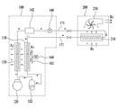
도 1은 본 발명의 일실시예에 따른 공기조화기의 구조도이다.
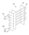
도 2는 본 발명에 따른 공기조화기용 실외기에 설치된 실외측 증발기의 예시도이다.
도 3은 도 2에 도시한 실외측 증발기를 구성하는 냉매관 및 이에 연결되는 냉매배관의 길이방향 단면을 예시한다.
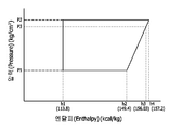
도 4는 본 발명에 따른 공기조화기용 실외기를 이용하는 경우의 에너지 절감 효과를 설명하는 예시적인 엔탈피 선도이다.
도 5는 본 발명의 다른 실시예에 따른 공기조화기의 구조도이다.1 is a structural view of an air conditioner according to an embodiment of the present invention.
2 is an exemplary view of an outdoor side evaporator installed in an outdoor unit for an air conditioner according to the present invention.
FIG. 3 illustrates a longitudinal section of a refrigerant pipe and a refrigerant pipe connected to the refrigerant pipe constituting the outdoor side evaporator shown in FIG.
4 is an exemplary enthalpy diagram illustrating the energy saving effect in the case of using an outdoor unit for an air conditioner according to the present invention.
5 is a structural view of an air conditioner according to another embodiment of the present invention.
본 발명은 다양한 변경을 가할 수 있고 여러 가지 실시예를 가질 수 있는 바, 특정 실시예들을 도면에 예시하고 이를 상세한 설명을 통해 상세히 설명하고자 한다. 그러나, 이는 본 발명을 특정한 실시 형태에 대해 한정하려는 것이 아니며, 본 발명의 사상 및 기술 범위에 포함되는 모든 변경, 균등물 내지 대체물을 포함하는 것으로 이해되어야 한다.While the present invention has been described in connection with certain exemplary embodiments, it is to be understood that the invention is not limited to the disclosed embodiments, but, on the contrary, is intended to cover various modifications and similarities. It should be understood, however, that the invention is not intended to be limited to the particular embodiments, but includes all modifications, equivalents, and alternatives falling within the spirit and scope of the invention.
본 발명을 설명함에 있어서, 관련된 공지 기술에 대한 구체적인 설명이 본 발명의 요지를 불필요하게 흐릴 수 있다고 판단되는 경우 그 상세한 설명을 생략한다. 아울러, 본 명세서에서, 일 구성요소가 다른 구성요소와 "연결된다" 거나 "접속된다" 등으로 언급된 때에는, 상기 일 구성요소가 상기 다른 구성요소와 직접 연결되거나 또는 직접 접속될 수도 있지만, 특별히 반대되는 기재가 존재하지 않는 이상, 중간에 또 다른 구성요소를 매개하여 연결되거나 또는 접속될 수도 있다고 이해되어야 할 것이다.DETAILED DESCRIPTION OF THE PREFERRED EMBODIMENTS Hereinafter, the present invention will be described in detail with reference to the accompanying drawings. Also, in this specification, when an element is referred to as being "connected" or "connected" with another element, the element may be directly connected or directly connected to the other element, It should be understood that, unless an opposite description is present, it may be connected or connected via another element in the middle.
이하, 첨부된 도면들을 참조하여 본 발명의 실시를 위한 구체적인 내용을 설명하도록 한다.Hereinafter, embodiments of the present invention will be described in detail with reference to the accompanying drawings.
먼저, 도 1에는 본 발명의 일 실시예에 따른 에너지절약형 실외기(100)를 포함하는 공기조화기의 전체 시스템의 구조도를 도시하였다. 여기서, 실내기(200)의 본체 내에는 실내측 증발기(210)가 설치되어 있으며, 실내공기(B1)는 송풍팬(230)에 의해 실내기(200)의 본체 내부로 유입된다. 유입된 실내공기(B1)는 실내측 증발기(210) 내부에서 유동되는 냉매와의 열교환 작용에 의해 냉각된다. 이렇게 형성된 냉각공기(B2)가 다시 실내로 토출된다. 그리고, 실외기(100)는 냉매배관(171)에 의해 순차적으로 연결된 실외측 증발기(110), 압축기(120), 응축기(130) 및 팽창수단(140)이 소정의 케이싱 내부에 설치되어 구성된다. 여기서, 냉매배관(171)은 실내기(200), 즉 실내측 증발기(210)로부터 유입된 냉매가, 실외측 증발기(110), 압축기(120), 응축기(130) 및 팽창수단(140)의 순서로 통과한 후, 다시 실내측 증발기(210)로 유출되는 방식으로 순환되도록 냉매의 유동경로를 형성한다. 참고로 도 1에서 냉매배관(171) 주변에 도시된 화살표는 냉매가 유동되는 방향을 가리킨다.1 is a structural view of an overall system of an air conditioner including an energy-saving
본 실시예에서, 실외기(100)에는, 실외측 증발기(110)를 통과한 냉매가 기체상 및 액체상으로 혼재되어 있는 경우, 액상을 분리하여 기체 냉매만을 압축기(120)로 유출하는 액분리기(122)가 추가로 설치될 수 있다. 또한, 응축기(130) 및 팽창수단(140) 사이에는, 예컨대 냉매액 저장탱크, 냉매 필터/드라이어, 냉매 액면계 등과 같은 보조장치(142)가 추가로 설치될 수 있다. 그리고, 실내측 증발기(210), 실외측 증발기(110) 및 응축기(130)는 각각, 냉매가 통과하는 유로가 형성된 냉매관 및 이 냉매관과 결합되어 전열 능력을 높이는 전열핀을 포함하는 이른바 핀엔튜브형(Fin AND Tube Type) 열교환기 구조로 형성될 수 있으며, 이외에도 플랫튜브형(Flat-Tube Type) 열교환기 구조를 가질 수도 있다. 아울러, 압축기(120)는 유입된 기체 냉매를 압축시키는 장치이다.In the present embodiment, when the refrigerant that has passed through the
본 발명에 따른 실외기(200)의 기능 및 작용에 대해서 설명하면, 먼저 실내측 증발기(210)로 유입된 냉매는 실내공기(B1)과 열교환됨에 따라 증발된다. 이때, 실내측 증발기(210)에서 1차 증발한 냉매의 증발량은 유입된 냉매량 대비 약 75wt% 내지 85wt% 정도이고, 따라서 실외기(200)로 유입되는 냉매는 냉매기체 및 냉매액이 혼재된 상태이다. 이렇게 기체상 및 액체상이 혼재된 냉매는 냉매배관(171)을 통해 실외기(200)에 설치된 실외측 증발기(110)에서 재증발된다.The function and operation of the
한편, 실외측 증발기(110)는, 도 2에서 보듯이, 냉매가 통과하는 유로가 형성된 냉매관(112)을 포함하여 구성될 수 있고, 추가적으로 전열 능력을 향상시키기 위하여 절열핀(114)이 부설된 핀엔튜브형으로 형성될 수 있다. 여기서, 도 2 및 도 3에서 보듯이, 실외측 증발기(110)를 구성하는 냉매관(112)에 형성된 유로의 내경(D)은, 실외측 증발기(110)로 냉매가 유입되는 유입구(112a)의 내경(D1)보다 작게 형성되는 것이 바람직하다. 아울러, 실외측 증발기(110)로부터 냉매가 유출되는 유출구(112b)의 내경(D2)은, 냉매관(112)에 형성된 유로의 내경(D)과 실질적으로 동일하거나 크게 형성된 것이 바람직하다. 예컨대, 실내측 증발기(210)와 실외측 증발기(110) 사이에 연결된 냉매배관(171)의 내경(D1)은 5/8 인치(inch)의 치수를 갖고, 실외측 증발기(110)를 구성하는 냉매관(112)의 내경(D)은 3/8 인치(inch)로 형성될 수 있다. 그리고, 실외측 증발기(110)와 압축기(120) 사이의 냉매배관(171)의 내경(D2)은 냉매관(112)의 내경(D)과 동일한 치수로 형성될 수 있다.
2, the
*다시 도 1로 돌아가서, 실내기(200)로부터 기체상 및 액체상이 혼재된 상태의 냉매가 실외측 증발기(110)로 유입되면, 냉매가 통과하는 단위면적이 감소함에 따라 재압축된다. 즉, 도 3에서 보듯이, 냉매관(112)의 내경(D)이 유입구(112a)의 냉매배관의 내경(D1)보다 작기 때문에, 유입되는 냉매(Rin)가 통과하는 단위면적이 감소(D1>D)함에 따라 압력이 증가하게 되어 냉매(R)가 압축된다. 예컨대, 유입되는 냉매(Rin)가 기상 75wt% 및 액상 25wt%을 포함한다면, 실외측 증발기(110) 내부로 유입된 냉매(R)는 기상 65wt% 및 액상 35wt%를 포함하게 된다.Returning to FIG. 1, when the refrigerant in a state in which the gas phase and the liquid phase are mixed from the
한편, 실외기(200) 내부에는 실외공기를 흡입하여 다시 외부로 토출시키는 모터(160) 및 팬(162)을 포함하는 송풍장치가 추가적으로 설치될 수 있다. 또한, 실외측 증발기(110) 및 응축기(130)는 실외기(100)의 본체 내부에서 서로 인접하게 배치되는 것이 바람직하다. 아울러, 실외기(100)에 설치된 송풍장치는 실외공기(A1)를 흡입하여 실외측 증발기(110) 및 응축기(130)를 순차적으로 통과하여 외부로 토출시키도록 설치된다.Meanwhile, a blowing device including a
이러한 송풍장치에 의해 흡입된 실외공기(A1)가 실외측 증발기(110) 내부를 유동하는 냉매(R)와 열교환된다. 즉, 더운 실외공기(A1)가 실외측 증발기(110) 내부를 유동하는 냉매(R)와 열교환되고, 그에 의해 냉매(R)는 열을 흡수하여 증발되고, 실외측 증발기(110)를 통과한 실외공기는 냉각된다. 예컨대, 실외공기(A1)와의 열교환됨에 따라, 실외측 증발기(110)로부터 유출되는 냉매(Rout)는 기상 95% 및 액상 5%를 포함하게 된다. 이와 같이, 실외기(200)로 최초 유입되는 냉매(Rin)는 액체상 비율이 약 25wt%이나, 실외측 증발기(110)에서 재증발된 냉매(Rout)는 액체상 비율이 약 5wt%로 감소하게 된다. 따라서, 상술한 구조의 실외측 증발기(110)를 부설함으로써, 냉매에 포함된 액체상의 비율을 상대적으로 더 낮출 수 있고, 동시에 외부로부터 흡입된 실외공기(A1)를 냉각시켜 응축기(130) 측으로 배출시킬 수 있다.The outdoor air (A1) sucked by the air blowing device is heat-exchanged with the refrigerant (R) flowing in the outdoor side evaporator (110). That is, the hot outdoor air A1 is heat-exchanged with the refrigerant R flowing in the
이렇게 실외측 증발기(110)를 통과한 냉매(Rout)는 압축기(120)로 유입되어 상온에서 액화하기 쉬운 기체 냉매로 압축된다. 여기서, 압축기(120)로 보내기 전에 액분리기(122)에 의해 냉매액을 분리할 수 있다. 이 경우, 앞에서 설명한 바와 같이, 본 발명에 따른 실외기(100)에서는 실외측 증발기(110)를 통과한 냉매에 포함된 액체상이 비율이 종래의 공기조화기용 실외기의 경우보다 더 감소하게 되므로, 냉매의 효율적 사용에 더욱 유리하다.The refrigerant Rout which has passed through the
다음으로, 압축기(120)에서 압축된 기체냉매는 응축기(130)로 유입된다. 응축기(130)를 통과하는 냉매는 실외측 증발기(110)를 통과한 실외공기와 열교환되어 액체냉매로 응축된다. 이때, 실외기(100) 내부로 최초 흡입된 실외공기(A1)는 실외측 증발기(110)를 통과하면서 냉각된 후에 응축기(130)를 통과하게 되므로, 최초 흡입된 실외공기(A1)가 직접 응축기(130)를 통과하는 경우(종래의 공기조화기용 실외기)보다 응축압력을 더 낮추게 된다. 즉, 실외측 증발기(110)에 의해 응축기(130)에 더 낮은 온도의 공기를 공급할 수 있고, 그에 따라 응축기(130) 내에서 액화될 수 있는 응축압력을 더 낮출 수 있다. 이는 궁극적으로 공기조화기의 소비동력을 줄이면서 동시에 성능계수(COP; Coefficient of Performance)를 향상시키는 효과를 유도한다.Next, the gas refrigerant compressed by the
즉, 도 4를 참조하여, 응축압력의 감소에 따라 성능계수가 향상되는 효과를 설명하면 다음과 같다. 도 4에는 종래의 공기조화기에서의 냉매사이클과 본 발명에 따른 실외기를 적용한 공기조화기에서의 냉매사이클을 비교하기 위하여 나타낸 예시적인 엔탈피 선도이다. 도 4의 엔탈피 선도를 통해 COP를 산출하면 다음과 같다.That is, referring to FIG. 4, the effect of improving the coefficient of performance according to the decrease of the condensation pressure will be described as follows. 4 is an exemplary enthalpy diagram for comparing refrigerant cycles in an air conditioner using a refrigerant cycle in a conventional air conditioner and an outdoor unit according to the present invention. The COP can be calculated by the enthalpy diagram of FIG. 4 as follows.
먼저, 엔탈피 선도를 통해 냉매사이클의 성능계수는 다음의 수학식 1에 의해 산출된다.
First, the performance coefficient of the refrigerant cycle through the enthalpy diagram is calculated by the following equation (1).
[수학식 1] : 성능계수(COP) = 냉동효과(qc) ÷ 압축일량(AW)
(COP) = refrigeration effect (qc) / compression amount (AW)
여기서, 종래의 공기조화기의 냉매사이클에서 응축압력을 "P2"인 경우, 성능계수는 아래 수학식 2에 의해 산출된다.
Here, when the condensation pressure in the refrigerant cycle of the conventional air conditioner is "P2 ", the coefficient of performance is calculated by the following equation (2).
[수학식 2]&Quot; (2) "
(1) 냉동효과(qc) = h2 - h1(1) Refrigeration effect (qc) = h2 - h1
(2) 압축일량(AW) = h4 - h2(2) Compression amount (AW) = h4 - h2
(3) 성능계수(COP) = (h2 - h1) / (h4 - h2)
(3) The coefficient of performance (COP) = (h2 - h1) / (h4 - h2)
한편, 본 발명에 따른 공기조화기의 냉매사이클에서 응축압력은 "P3"로 낮아지게 되며, 따라서 성능계수는 아래 수학식 3에 의해 산출된다.
On the other hand, in the refrigerant cycle of the air conditioner according to the present invention, the condensation pressure is lowered to "P3 ", and therefore the coefficient of performance is calculated by the following equation (3).
[수학식 3]&Quot; (3) "
(1) 냉동효과(qc) = h3 - h1(1) Freezing effect (qc) = h3 - h1
(2) 압축일량(AW) = h3 - h2(2) Compression amount (AW) = h3 - h2
(3) 성능계수(COP) = (h3 - h1) / (h3 - h2)
(3) The coefficient of performance (COP) = (h3 - h1) / (h3 - h2)
예시적으로, 도 4에 도시한 엔탈피 선도에서, h1=113.8, h2=149.4, h3=155.2 및 h4=157.2 라 하면, 수학식 1에 의해 산출된 종래의 공기조화기의 성능계수(COP)는 4.56이고, 수학식 2에 의해 산출된 본 발명에 따른 공기조화기의 성능계수(COP)는 5.37이다. 따라서, 본 발명에 따른 공기조화기는 종래의 경우보다 1.17배 더 효율이 향상됨을 알 수 있다.
Illustratively, assuming that h1 = 113.8, h2 = 149.4, h3 = 155.2 and h4 = 157.2 in the enthalpy diagram shown in Fig. 4, the coefficient of performance (COP) of the conventional air conditioner calculated by Equation 4.56, and the coefficient of performance (COP) of the air conditioner according to the present invention calculated by Equation (2) is 5.37. Therefore, it can be seen that the efficiency of the air conditioner according to the present invention is improved by 1.17 times as compared with the conventional case.
다음으로, 응축기(130)를 통과한 실외공기는 응축기(130) 내부를 유동하는 냉매와 열교환된 후 외부로 토출된다(A2). 그리고, 응축기(130)를 통과한 냉매는 팽창수단(140)에 의해 저온저압의 냉매로 감압된다. 팽창수단(140)으로는 전자팽창밸브를 이용할 수 있으며, 팽창과정에서 냉매액이 증발되기 쉬운 상태로 된 후, 냉매배관(171)을 통해 다시 실내기(200)에 설치된 실내측 증발기(210)로 유출된다.Next, the outdoor air having passed through the
상술한 구조의 실외기(200)를 이용하여 공기조화기 시스템을 가동하는 경우, 냉매는 실내기(100)에서의 1차 증발, 실외기(200)의 실외측 증발기(110)에서의 2차 증발, 압축기(120)에서의 압축, 응축기에서 상대적으로 낮은 압력에서의 응축 및 팽창의 과정을 반복하면서 순환하게 된다. 이에 따라, 실외측 증발기(110)를 통과한 실외공기가 냉각된 후에 응축기(130)를 통과하게 되므로, 상대적으로 낮은 온도의 실외공기가 응축기(130) 내부의 냉매와 열교환되게 함으로써 응축기 내부의 압력을 낮추게 되고, 그에 따라 공기조화기의 성능계수를 향상시키고 소비전력을 절감하는 효과를 유도하게 된다.When the air conditioner system is operated using the
다음으로, 도 5에는 본 발명의 다른 실시예에 따른 에너지절약형 실외기(100)를 포함하는 공기조화기의 전체 시스템의 구조도를 도시하였다. 도 5에 도시한 실시예는 도 1에 도시한 실시예에 포함된 구성을 모두 포함하면서, 추가적으로 브라인 열교환 시스템을 포함한다. 여기서, 브라인(Brine)은 냉동사이클에 의해 외부를 순환하면서 열을 운반해 주는 매개체로서, 염화칼슘, 염화나트륨, 염화마그네슘, 물 등을 이용할 수 있다.Next, FIG. 5 shows a structural diagram of an entire system of an air conditioner including an energy-saving
브라인 열교환 시스템은, 실내기(200)에 설치된 실내측 브라인코일(220)과, 실외기(100)에 설치된 브라인 저장탱크(152), 실내측 브라인코일(150) 및 브라인펌프(151)를 포함하여 구성될 수 있다. 이에 의해, 브라인펌프(151)에 의해 브라인이 브라인배관(172)을 따라 유동하면서 실내측 브라인코일(220) 및 실외측 브라인코일(150) 사이를 순환하게 된다. 참고로, 도 5에서 브라인배관(172) 주변에 표시된 화살표는 브라인이 순환되는 방향을 가리킨다.The brine heat exchange system includes the indoor
도 5에 도시한 실시예에 따른 공기조화기를 겨울철에 가동하는 경우, 실외기(100)에 설치된 송풍장치(160, 162)에 의해 흡입된 차가운 실외공기(A1)가 실외측 브라인코일(150) 내부를 유동하는 브라인과 열교환되고, 이렇게 냉각된 브라인이 브라인펌프(151)에 의해 실내기(200)에 설치된 실내측 브라인코일(220)로 유출된다. 실내측 브라인코일(220)을 따라 흐르는 냉각된 브라인은 열교환에 의해 실내공기(B1)의 온도를 낮추게 된다. 이와 같이, 브라인 열교환 시스템을 이용하면, 겨울철에도 차가운 실외공기를 이용하여 실내를 쾌적한 상태로 유지할 수 있으므로 에너지 절감에 더욱 유리하고, 특히 전자부품의 생산설비, 전산실 등과 같이 항온항습이 요구되는 공간에 효과적으로 사용할 수 있다.When the air conditioner according to the embodiment shown in FIG. 5 is operated in winter, the cold outdoor air A1 sucked by the blowing
한편, 실외측 브라인코일(150)은 실외측 증발기(110)에 인접하게 배치되는 것이 바람직하다. 즉, 실외측 브라인코일(150)은, 응축기(130)가 배치된 실외측 증발기(110)의 일측에 대향하는 타측에 인접하게 배치되는 것이 바람직하다. 이러한 배치에 따라, 실외기(100) 내부로 흡입된 실외공기(A1)가 실외측 브라인코일(150), 실외측 증발기(110) 및 응축기(130)의 순서로 통과하여 외부로 토출될 수 있다.On the other hand, the outdoor
도 5에 따른 공기조화기용 실외기를 이용하면, 사계절 내내 가동되는 공기조화기의 소비전력을 절감할 수 있다. 즉, 실외공기의 온도가 높은 여름철에는 실외측 증발기(110)를 통해 응축기(130)의 응축압력을 낮춤으로써 성능계수를 향상시킬 수 있고, 실외공기의 온도가 낮은 겨울철에는 실외측 브라인코일(150)만을 가동하여 실내 공간을 냉방시킴으로써 소비전력을 절감할 수 있다. 또한, 봄과 가을과 같은 중간기에는 실외기(100) 및 실내기(200)에 온도센서를 구비하여, 실외온도와 실내온도 차이에 따라 실외측 증발기(110) 및 실외측 브라인코일(150)을 동시에 또는 개별적으로 가동할 수도 있다.
By using the outdoor unit for the air conditioner according to FIG. 5, it is possible to reduce the power consumption of the air conditioner operated throughout the entire season. That is, the performance coefficient can be improved by reducing the condensation pressure of the
본 발명에 따른 공기조화기용 실외기에 따른 에너지 절감 효과를 종래의 공기조화기와 비교하면 다음과 같다. 즉, 표 1에는 동일한 구성부품을 사용하여 공기조화기(30HP 기준)를 구성하는 경우에, 비교예, 실시예 1 및 실시예 2에 따른 공기조화기의 기기별 전력량을 나타내었다. 여기서, 비교예는 종래의 공기조화기를 나타내고, 실시예 1은 도 1에 도시한 공기조화기를 나타내며, 실시예 2는 도 5에 도시한 공기조화기에서 브라인 냉각시스템을 가동하는 경우를 나타낸다.
The energy saving effect of the outdoor unit for the air conditioner according to the present invention is compared with the conventional air conditioner as follows. That is, Table 1 shows the power amount of the air conditioner according to the comparative example, the first embodiment and the second embodiment when the air conditioner (30HP standard) is constituted by using the same component parts. Here, the comparative example shows a conventional air conditioner, the first embodiment shows the air conditioner shown in Fig. 1, and the second embodiment shows a case where the brine cooling system is operated in the air conditioner shown in Fig.
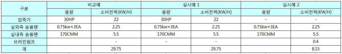
표 1에 따른 전력량을 구성부품을 사용한 경우에, 비교예, 실시예 1 및 실시예 2의 장비사용 분석결과를 표 2 내지 표 4에 나타내었다.
Table 2 to Table 4 show the results of the equipment use analysis of the comparative example, the first embodiment and the second embodiment when the component parts are used in accordance with the electric power amounts shown in Table 1. [
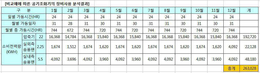


아울러, 표 5에는 표 2 내지 표 4에서 분석된 비교예, 실시예 1 및 실시예 2의 장비사용결과를 기초로 연간 전기에너지 사용량 및 사용금액을 나타내었다. 여기서, "차이" 및 "절감율"은, 도 5에 도시한 본 발명에 따른 공기조화기에서 압축기에 의한 냉각사이클 및 브라인펌프에 의한 브라인 냉각 사이클을 모두 가동한 경우에, 비교예와의 사용전력량 및 전력사용금액의 차이[즉, "(비교예)-(실시예 1)-(실시예 2)"의 값)와 그에 따른 절감율[즉, "{(실시예 1)+(실시예 2)}/(비교예)×100"의 값)을 나타낸다.
Table 5 shows the annual electric energy usage amount and the usage amount based on the results of the use of the apparatuses of Comparative Examples, Examples 1 and 2 analyzed in Tables 2 to 4. Here, the "difference" and the " reduction rate "indicate that when both the cooling cycle by the compressor and the brine cooling cycle by the brine pump are operated in the air conditioner according to the present invention shown in Fig. 5, (Example 1) + (Example 2)) and the power saving amount (that is, the value of "(Comparative Example) - (Example 1) - (Example 2) } / (Comparative example) x 100 ").

지금까지 본 발명의 바람직한 실시예에 대해 설명하였으나, 본 발명이 속하는 기술분야에서 통상의 지식을 가진 자는 본 발명의 본질적인 특성을 벗어나지 않는 범위 내에서 변형된 형태로 구현할 수 있을 것이다. 그러므로 여기서 설명한 본 발명의 실시예는 한정적인 관점이 아니라 설명적인 관점에서 고려되어야 하고, 본 발명의 범위는 상술한 설명이 아니라 특허청구범위에 나타나 있으며, 그와 동등한 범위 내에 있는 모든 차이점은 본 발명에 포함되는 것으로 해석되어야 한다.While the present invention has been particularly shown and described with reference to exemplary embodiments thereof, it is to be understood that the invention is not limited to the disclosed embodiments, but, on the contrary, is intended to cover various modifications and equivalent arrangements included within the spirit and scope of the invention. It is therefore to be understood that the embodiments of the invention described herein are to be considered in all respects as illustrative and not restrictive, and the scope of the invention is indicated by the appended claims rather than by the foregoing description, Should be interpreted as being included in.
Claims (6)
상기 실내기로부터 유입된 냉매를 재증발시키는 실외측 증발기;
상기 실외측 증발기를 통과한 냉매를 압축시키는 압축기;
상기 압축기를 통과한 냉매를 응축시키는 응축기;
상기 응축기를 통과한 냉매를 팽창시키는 팽창수단; 및
상기 실내기로부터 유입된 냉매가 상기 실외측 증발기, 상기 압축기, 상기 응축기 및 상기 팽창수단의 순서로 통과된 후에 상기 실내기로 유출되도록 냉매의 유동 경로를 형성하는 냉매배관;을 포함하고,
상기 실외기 내부로 흡입된 실외공기가 상기 실외측 증발기 및 상기 응축기를 순차적으로 통과하여 외부로 토출되며,
상기 실외측 증발기는 냉매가 통과하는 유로가 형성된 냉매관을 포함하고,
상기 실외측 증발기의 상기 냉매관에 형성된 상기 유로의 내경(D)은, 상기 실외측 증발기로 냉매가 유입되는 유입구의 내경(D1)보다 작은 것을 특징으로 하는, 공기조화기용 실외기.
1. An outdoor unit for an air conditioner, which is connected to an indoor unit provided with an indoor-side evaporator for exchanging heat with indoor air while passing a refrigerant,
An outdoor side evaporator for re-evaporating the refrigerant introduced from the indoor unit;
A compressor for compressing the refrigerant passing through the outdoor side evaporator;
A condenser for condensing the refrigerant passing through the compressor;
Expansion means for expanding the refrigerant passing through the condenser; And
And a refrigerant pipe which forms a flow path of the refrigerant so that the refrigerant introduced from the indoor unit flows out to the indoor unit after passing through the outdoor side evaporator, the compressor, the condenser, and the expansion means in this order,
The outdoor air sucked into the outdoor unit sequentially passes through the outdoor side evaporator and the condenser and is discharged to the outside,
Wherein the outdoor side evaporator includes a refrigerant pipe in which a flow path through which the refrigerant passes is formed,
Wherein an inner diameter (D) of the flow path formed in the refrigerant pipe of the outdoor side evaporator is smaller than an inner diameter (D1) of an inlet through which the refrigerant flows into the outdoor side evaporator.
상기 실외기 내부로 흡입된 실외공기는 상기 실외측 증발기와 열교환되어 냉각된 후 상기 응축기를 거쳐 외부로 토출되는 것을 특징으로 하는, 공기조화기용 실외기.
The method according to claim 1,
Wherein the outdoor air sucked into the outdoor unit is heat-exchanged with the outdoor-side evaporator, cooled, and then discharged to the outside through the condenser.
상기 실외측 증발기 및 상기 응축기는 서로 인접하게 배치된 것을 특징으로 하는, 공기조화기용 실외기.
The method according to claim 1,
Wherein the outdoor side evaporator and the condenser are disposed adjacent to each other.
상기 실내기에 설치된 실내측 브라인코일과 연결된 실외측 브라인코일을 더 포함하는 것을 특징으로 하는, 공기조화기용 실외기.
The method according to claim 1,
And an outdoor side brine coil connected to the indoor side brine coil installed in the indoor unit.
상기 실외기 내부로 흡입된 실외공기가 상기 실외측 브라인코일, 상기 실외측 증발기 및 상기 응축기를 순차적으로 통과하여 외부로 토출되는 것을 특징으로 하는, 공기조화기용 실외기.
5. The method of claim 4,
Wherein the outdoor air sucked into the outdoor unit passes through the outdoor side brine coil, the outdoor side evaporator, and the condenser sequentially and is discharged to the outside.
제 1 항 내지 제 6 항 중 어느 한 항에 따른 공기조화기용 실외기;를 포함하는 공기조화기.An indoor unit having an indoor-side evaporator for exchanging heat with indoor air while passing through the refrigerant; And
An air conditioner comprising an outdoor unit for an air conditioner according to any one of claims 1 to 6.
Priority Applications (1)
| Application Number | Priority Date | Filing Date | Title |
|---|---|---|---|
| KR1020160006366A KR101646147B1 (en) | 2016-01-19 | 2016-01-19 | Air conditioner including outdoor device |
Applications Claiming Priority (1)
| Application Number | Priority Date | Filing Date | Title |
|---|---|---|---|
| KR1020160006366A KR101646147B1 (en) | 2016-01-19 | 2016-01-19 | Air conditioner including outdoor device |
Related Parent Applications (1)
| Application Number | Title | Priority Date | Filing Date |
|---|---|---|---|
| KR1020140049876A Division KR20150123497A (en) | 2014-04-25 | 2014-04-25 | Energy-saving outdoor device, and air conditioner including the same |
Publications (2)
| Publication Number | Publication Date |
|---|---|
| KR20160010643A true KR20160010643A (en) | 2016-01-27 |
| KR101646147B1 KR101646147B1 (en) | 2016-08-05 |
Family
ID=55309608
Family Applications (1)
| Application Number | Title | Priority Date | Filing Date |
|---|---|---|---|
| KR1020160006366A KR101646147B1 (en) | 2016-01-19 | 2016-01-19 | Air conditioner including outdoor device |
Country Status (1)
| Country | Link |
|---|---|
| KR (1) | KR101646147B1 (en) |
Citations (4)
| Publication number | Priority date | Publication date | Assignee | Title |
|---|---|---|---|---|
| JPS63101640A (en) * | 1986-10-17 | 1988-05-06 | Matsushita Seiko Co Ltd | Air conditioner |
| KR20060128129A (en) * | 2005-06-09 | 2006-12-14 | 엘지전자 주식회사 | Air-condition |
| JP2010501826A (en) * | 2006-09-01 | 2010-01-21 | チャンジョ 21 シーオー.,エルティディ. | Air conditioner for communication equipment |
| JP2010531426A (en) * | 2007-06-28 | 2010-09-24 | エクソンモービル リサーチ アンド エンジニアリング カンパニー | Vibration Mitigation Method for Plate Heat Exchanger Port Insert and Heat Exchanger |
-
2016
- 2016-01-19 KR KR1020160006366A patent/KR101646147B1/en active IP Right Grant
Patent Citations (4)
| Publication number | Priority date | Publication date | Assignee | Title |
|---|---|---|---|---|
| JPS63101640A (en) * | 1986-10-17 | 1988-05-06 | Matsushita Seiko Co Ltd | Air conditioner |
| KR20060128129A (en) * | 2005-06-09 | 2006-12-14 | 엘지전자 주식회사 | Air-condition |
| JP2010501826A (en) * | 2006-09-01 | 2010-01-21 | チャンジョ 21 シーオー.,エルティディ. | Air conditioner for communication equipment |
| JP2010531426A (en) * | 2007-06-28 | 2010-09-24 | エクソンモービル リサーチ アンド エンジニアリング カンパニー | Vibration Mitigation Method for Plate Heat Exchanger Port Insert and Heat Exchanger |
Also Published As
| Publication number | Publication date |
|---|---|
| KR101646147B1 (en) | 2016-08-05 |
Similar Documents
| Publication | Publication Date | Title |
|---|---|---|
| CN100557337C (en) | Heating vent air regulating system with power-actuated aftercooler | |
| US7464563B2 (en) | Air-conditioner having a dual-refrigerant cycle | |
| US11555635B2 (en) | Systems and methods for cooling electrical equipment | |
| WO2016079834A1 (en) | Air conditioning device | |
| WO2016208042A1 (en) | Air-conditioning device | |
| JP4389917B2 (en) | Air conditioner | |
| US10914476B2 (en) | Method for sequencing compressor operation based on space humidity | |
| JP2005114253A (en) | Air conditioner | |
| KR20100059176A (en) | Storage system | |
| JP2008008593A (en) | Refrigeration system | |
| JPH09196489A (en) | Refrigeration cycle for air conditioner | |
| KR20100046365A (en) | Heat pump system | |
| KR20100120323A (en) | Chiller system | |
| KR101646147B1 (en) | Air conditioner including outdoor device | |
| KR20100005736U (en) | Heat pump system | |
| US20150047385A1 (en) | Partitioned evaporator for a reversible heat pump system operating in the heating mode | |
| KR20070031783A (en) | Air conditioning system for communication equipment and controlling method thereof | |
| KR20150123497A (en) | Energy-saving outdoor device, and air conditioner including the same | |
| EP2889560B1 (en) | Refrigerating device | |
| KR101157498B1 (en) | Heat pump for energy saving type clean-room in hvac system | |
| KR102260447B1 (en) | Air conditioning system for refrigerating and freezing | |
| KR20050043089A (en) | Heat pump | |
| CN105556219A (en) | Freezer | |
| KR102261131B1 (en) | Heat pump air-conditioner having defrosting | |
| KR101609220B1 (en) | Energy-saving constant temperature and humidity controlling device |
Legal Events
| Date | Code | Title | Description |
|---|---|---|---|
| A107 | Divisional application of patent | ||
| E902 | Notification of reason for refusal | ||
| E701 | Decision to grant or registration of patent right | ||
| GRNT | Written decision to grant |