KR20160006749A - Caliper disc brake of a vehicle, in particular a commercial vehicle, and brake caliper of such a brake - Google Patents
Caliper disc brake of a vehicle, in particular a commercial vehicle, and brake caliper of such a brake Download PDFInfo
- Publication number
- KR20160006749A KR20160006749A KR1020157034942A KR20157034942A KR20160006749A KR 20160006749 A KR20160006749 A KR 20160006749A KR 1020157034942 A KR1020157034942 A KR 1020157034942A KR 20157034942 A KR20157034942 A KR 20157034942A KR 20160006749 A KR20160006749 A KR 20160006749A
- Authority
- KR
- South Korea
- Prior art keywords
- brake
- caliper
- restraining
- brake caliper
- retaining
- Prior art date
Links
Images


Classifications
-
- F—MECHANICAL ENGINEERING; LIGHTING; HEATING; WEAPONS; BLASTING
- F16—ENGINEERING ELEMENTS AND UNITS; GENERAL MEASURES FOR PRODUCING AND MAINTAINING EFFECTIVE FUNCTIONING OF MACHINES OR INSTALLATIONS; THERMAL INSULATION IN GENERAL
- F16D—COUPLINGS FOR TRANSMITTING ROTATION; CLUTCHES; BRAKES
- F16D65/00—Parts or details
- F16D65/02—Braking members; Mounting thereof
- F16D65/04—Bands, shoes or pads; Pivots or supporting members therefor
- F16D65/092—Bands, shoes or pads; Pivots or supporting members therefor for axially-engaging brakes, e.g. disc brakes
- F16D65/095—Pivots or supporting members therefor
- F16D65/097—Resilient means interposed between pads and supporting members or other brake parts
- F16D65/0973—Resilient means interposed between pads and supporting members or other brake parts not subjected to brake forces
- F16D65/0974—Resilient means interposed between pads and supporting members or other brake parts not subjected to brake forces acting on or in the vicinity of the pad rim in a direction substantially transverse to the brake disc axis
- F16D65/0977—Springs made from sheet metal
- F16D65/0978—Springs made from sheet metal acting on one pad only
-
- F—MECHANICAL ENGINEERING; LIGHTING; HEATING; WEAPONS; BLASTING
- F16—ENGINEERING ELEMENTS AND UNITS; GENERAL MEASURES FOR PRODUCING AND MAINTAINING EFFECTIVE FUNCTIONING OF MACHINES OR INSTALLATIONS; THERMAL INSULATION IN GENERAL
- F16D—COUPLINGS FOR TRANSMITTING ROTATION; CLUTCHES; BRAKES
- F16D55/00—Brakes with substantially-radial braking surfaces pressed together in axial direction, e.g. disc brakes
- F16D55/02—Brakes with substantially-radial braking surfaces pressed together in axial direction, e.g. disc brakes with axially-movable discs or pads pressed against axially-located rotating members
- F16D55/22—Brakes with substantially-radial braking surfaces pressed together in axial direction, e.g. disc brakes with axially-movable discs or pads pressed against axially-located rotating members by clamping an axially-located rotating disc between movable braking members, e.g. movable brake discs or brake pads
- F16D55/224—Brakes with substantially-radial braking surfaces pressed together in axial direction, e.g. disc brakes with axially-movable discs or pads pressed against axially-located rotating members by clamping an axially-located rotating disc between movable braking members, e.g. movable brake discs or brake pads with a common actuating member for the braking members
- F16D55/225—Brakes with substantially-radial braking surfaces pressed together in axial direction, e.g. disc brakes with axially-movable discs or pads pressed against axially-located rotating members by clamping an axially-located rotating disc between movable braking members, e.g. movable brake discs or brake pads with a common actuating member for the braking members the braking members being brake pads
-
- F—MECHANICAL ENGINEERING; LIGHTING; HEATING; WEAPONS; BLASTING
- F16—ENGINEERING ELEMENTS AND UNITS; GENERAL MEASURES FOR PRODUCING AND MAINTAINING EFFECTIVE FUNCTIONING OF MACHINES OR INSTALLATIONS; THERMAL INSULATION IN GENERAL
- F16D—COUPLINGS FOR TRANSMITTING ROTATION; CLUTCHES; BRAKES
- F16D65/00—Parts or details
- F16D65/005—Components of axially engaging brakes not otherwise provided for
- F16D65/0068—Brake calipers
-
- F—MECHANICAL ENGINEERING; LIGHTING; HEATING; WEAPONS; BLASTING
- F16—ENGINEERING ELEMENTS AND UNITS; GENERAL MEASURES FOR PRODUCING AND MAINTAINING EFFECTIVE FUNCTIONING OF MACHINES OR INSTALLATIONS; THERMAL INSULATION IN GENERAL
- F16D—COUPLINGS FOR TRANSMITTING ROTATION; CLUTCHES; BRAKES
- F16D65/00—Parts or details
- F16D65/02—Braking members; Mounting thereof
- F16D65/04—Bands, shoes or pads; Pivots or supporting members therefor
- F16D65/092—Bands, shoes or pads; Pivots or supporting members therefor for axially-engaging brakes, e.g. disc brakes
-
- F—MECHANICAL ENGINEERING; LIGHTING; HEATING; WEAPONS; BLASTING
- F16—ENGINEERING ELEMENTS AND UNITS; GENERAL MEASURES FOR PRODUCING AND MAINTAINING EFFECTIVE FUNCTIONING OF MACHINES OR INSTALLATIONS; THERMAL INSULATION IN GENERAL
- F16D—COUPLINGS FOR TRANSMITTING ROTATION; CLUTCHES; BRAKES
- F16D55/00—Brakes with substantially-radial braking surfaces pressed together in axial direction, e.g. disc brakes
- F16D2055/0004—Parts or details of disc brakes
- F16D2055/0041—Resilient elements interposed directly between the actuating member and the brake support, e.g. anti-rattle springs
-
- F—MECHANICAL ENGINEERING; LIGHTING; HEATING; WEAPONS; BLASTING
- F16—ENGINEERING ELEMENTS AND UNITS; GENERAL MEASURES FOR PRODUCING AND MAINTAINING EFFECTIVE FUNCTIONING OF MACHINES OR INSTALLATIONS; THERMAL INSULATION IN GENERAL
- F16D—COUPLINGS FOR TRANSMITTING ROTATION; CLUTCHES; BRAKES
- F16D55/00—Brakes with substantially-radial braking surfaces pressed together in axial direction, e.g. disc brakes
- F16D2055/0004—Parts or details of disc brakes
- F16D2055/007—Pins holding the braking members
Landscapes
- Engineering & Computer Science (AREA)
- General Engineering & Computer Science (AREA)
- Mechanical Engineering (AREA)
- Braking Arrangements (AREA)
Abstract
본 발명은 회전축을 갖는 브레이크 디스크, 브레이크 캘리퍼(20), 브레이크 앵커 플레이트(22), 브레이크 캘리퍼의 또는 브레이크 앵커 플레이트의 샤프트 내에서 안내되고 그리고 지지되는, 예를 들어 라이닝 지지체 (26) 및/또는 압력 플레이트와 같은 힘 전달 요소, 힘 전달 요소를 억제하기 위한 억제 스프링(32), 그리고 유지 장치에 의하여 캘리퍼 상에서 유지되고 지지되는 억제 장치(36)를 갖되, 억제 장치는 힘 전달 장치에 맞서 억제 스프링을 반경 방향적으로 프리-스트레스시키고 그리고 전방 주행 동안에 힘 전달 장치에 맞서 억제 스프링은 회전 방향으로 접선적으로 프리-스트레스시키며, 유지 장치는 회전 축에 평행하게 놓여진 중심선을 갖는 차량, 특히 사용 차량의 캘리퍼 디스크 브레이크를 개시한다. 접선 방향적 프리-스트레싱은 중심선에서 접선 방향으로 측정된 바와 같은 억제 장치의 적어도 단면의 크기는 디스크 유입측 상에서보다 디스크 출구측 상에서 더 크다는 점에 적어도 부분적으로 기인한다. The present invention relates to a braking device comprising a brake disc having a rotating shaft, a brake caliper (20), a brake anchor plate (22), a brake caliper or a brake anchor plate A restraining spring 32 for restraining a force transmitting element, and a restraining device 36, which is held and supported on the caliper by a retaining device, And the restraining spring tangentially pre-stresses in the direction of rotation against the force transmission device during forward travel, the retention device having a centerline that lies parallel to the axis of rotation, Initiates the caliper disc brake. Tangential pre-stretching is due, at least in part, to at least the size of at least the cross-section of the suppression device as measured in the tangential direction at the centerline is greater on the disc exit side than on the disc entry side.
Description
본 발명은 회전축을 갖는 브레이크 디스크; 브레이크 캘리퍼; 백 플레이트 조립체; 브레이크 캘리퍼 또는 백 플레이트 조립체의 채널 내에서 안내되고 그리고 지지된, 브레이크 패드 플레이트 및/또는 압력 플레이트와 같은 힘 전달 요소; 힘 전달 요소를 억제하기 위한 억제 스프링; 및 회전축과 평행하게 놓여진 중심선을 갖는 유지 장치에 의하여 캘리퍼 상에서 유지되고 그리고 지지되고, 힘 전달 장치에 맞서 억제 스프링을 반경적으로 프리-스트레스 하며 그리고 힘 전달 장치에 맞서 억제 스프링을 전진 주행의 회전 방향으로 접선적으로 프리-스트레스하는 억제 장치를 갖는, 차량, 특히 상용 차량의 캘리퍼 디스크 브레이크에 관한 것이다. The present invention relates to a brake disc having a rotating shaft; Brake calipers; A backplate assembly; A force transmission element, such as a brake pad plate and / or a pressure plate, guided and supported in the channel of the brake caliper or backplate assembly; A restraining spring for restraining a force transmitting element; And a retaining device having a centerline lying parallel to the axis of rotation, radially pre-stressing the restraining spring against the force transmitting device and restraining the restraining spring against the force transmitting device in the rotational direction of the forward travel To a caliper disc brake of a vehicle, particularly a commercial vehicle, having an inhibition device that tangentially pre-stresses the caliper disc brake.
위에서 언급된 형태의 브레이크가 예를 들어 EP 694 707B3에 의하여 개시되어 있다. 위에서 언급된 형태의 브레이크가 예를 들어 EP 694 707B3 내에 개시되어 있다. 이 목적을 위해 특히 형성된 억제 스프링 내에서의 적극적인 인터록킹 결합을 통하여 반경 방향적 프리-스트레싱뿐만 아니라 접선적 프리-스트레싱을 브레이크 라이닝에 가하기 위하여, 선행 기술에 따른 브레이크의 특징적 세부 특징은 브레이크 캘리퍼 내의 편심 인터록킹 지지를 통한 억제 요크의 축 방향 오프셋이다. A brake of the type mentioned above is disclosed, for example, in EP 694 707B3. A brake of the type mentioned above is disclosed, for example, in EP 694 707B3. In order to apply tangential pre-straining, as well as radial pre-straining, to the brake lining through aggressive interlocking engagement in the suppression spring formed specifically for this purpose, the characteristic detail of the brake according to the prior art, Is the axial offset of the suppression yoke through the eccentric interlocking support in the caliper.
반경 방향 그리고 접선적 프리-스트레싱의 기본 원리는 그 가치를 입증하고 있으며 그리고 유지되어야 한다. 그러나, 본 발명에 따르면, 더욱 큰 효율 그리고 더욱 큰 융통성을 제공하기 위하여 구조 그리고 기능적 변형이 브레이크 캘리퍼에 그리고 억제 시스템의 관련있는 부품에 대하여 이루어진다. The basic principles of radial and tangential pre-stretching are demonstrating its value and must be maintained. However, in accordance with the present invention, structural and functional modifications are made to brake calipers and associated parts of the containment system to provide greater efficiency and greater flexibility.
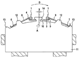
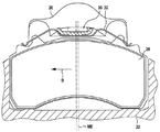
도 1 및 도 2는 EP 694 707 B3에 따른 브레이크를 도시한다. 여기서, 도 1은 브레이크 라이닝(11)을 도시하며, 이 브레이크 라이닝은 반경 방향으로 내측으로 그리고 양 측부 상에서 브레이크 캘리퍼 또는 백 플레이트 조립체의 채널 가이드 내에서 원주 방향으로 안내되고 그리고 지지되며, 그리고 브레이크 라이닝의 반경 방향 외부 에지 상에서 억제 스프링이 지지된다. 여기서 이 억제 스프링은 그 중심축의 양 측부에 대하여 대칭적으로 형성된다. 중심적으로, 억제 스프링은 반경 방향적으로 보다 깊은 중심 영역(3)을 포함하며, 동일하게 대칭적으로 형성된 억제 요크(1)가 반경적으로 내측에 형성된 중심 영역 내에서 확실한 인터록과 결합할 때 종단이 브레이크 라이닝 상에 스프링 작용을 가하도록 하기 위하여 더 높은 스프링 레그(6, 7)는 양 측부 상에서 중심 영역으로부터 라이닝의 외측 에지를 따라 외측으로 연장된다.Figures 1 and 2 show the brakes according to EP 694 707 B3. 1 shows a
억제 요크(1)는 둥근 재료로 형성된다. 도 2에서와 같이 억제 요크(1)가 브레이크 캘리퍼의 인터록 개구 내에서 작동 측에 고정되고 그리고 그후 다른 측 상에서 볼트에 의하여 휠 림 측 상의 브레이크 캘리퍼의 베어링 블록에 견고하게 그러나 분리 가능하게 고정될 때 스프링 프리-스트레싱이 발생한다. 억제 요크는 브레이크 디스크의 양 측 상에서 지지된 브레이크 라이닝의 끼워맞춤/제거를 위한 역할을 하는 캘리퍼 개구에 걸쳐 그리고 브레이크 또는 중심축(A)을 향하는 방향으로 연장된다. The suppressing
브레이크 라이닝의 외측 에지의 반경 방향 숄더(12, 14)가 스프링 내의 긴 개구(8, 9, 10)를 통과하기 때문에, 브레이크 라이닝의 축 방향으로 억제 스프링이 브레이크 라이닝에 결합된다. 결국, 스프링 레그는 브레이크 라이닝의 외측 에지의 다른 반경 방향 숄더(13, 13)에 받쳐있다. 억제 스프링은 리프 스프링(leaf spring)으로서 구현된다.Since the
선행 기술에 따르면, 억제 요크(1)가 억제 스프링의 반경 방향적으로 형성된 중심 영역(3) 내에서 확실한 인터록과 결합하고 그리고 결과적으로 중심 또는 브레이크 축(A)에 관한 축방향 오프셋(X)에 의하여 브레이크 디스크 런-아웃 측을 향하여 전방 주행에서의 회전 방향으로 항상 오프셋된 브레이크 캘리퍼의 작동 및 휠 림 측 고정 내에서 확실한 인터록에 의하여 지지된다는 점에서 억제 스프링에 의하여 브레이크 라이닝에 작용하는 반경 방향 그리고 접선 방향 프리-스트레싱이 발생된다. 그 결과, 대응하는 스프링 레그는 또한 접선 방향으로 힘을 받는다. 억제 요크(1)의 편심적인 견고한 인터록킹 지지를 위하여, 필요한 설계 형상이 브레이크 캘리퍼 주조 과정에서 대응하는 위치에 제공되어야 하며 그리고 이러한 설계 형상은 그후 가공 작업을 거쳐야만 한다. 따라서 억제 요크(1)는 브레이크 캘리퍼 상/내에서 비대칭적으로 형성된다. According to the prior art, the
관련있는 브레이크는 차축의 양 측에 끼워 맞추어지며 따라서 브레이크들은 거울 대칭 구조가 될 필요가 있다. 이는 비대칭적인 지지 및 유지 영역을 생성하기 위하여 선행 기술에 따른 브레이크 캘리퍼를 위해서는 좌측 브레이크와 우측 브레이크를 위한 다른 주조 패턴 구조가 요구된다는 것을 의미한다. 따라서 좌측 브레이크의 경우에 지지 및 유지 영역을 위한 후속 가공 작업의 위치는 우측 브레이크의 경우와는 다르다. Associated brakes are fitted to both sides of the axle and therefore the brakes need to be mirror symmetrical. This implies that for the brake caliper according to the prior art, another casting pattern structure is required for the left and right brakes to produce asymmetric support and retention areas. Therefore, in the case of the left brake, the position of the subsequent machining operation for the support and retention areas is different from that of the right brake.
위에서 언급된 비대칭 때문에, 다른 캘리퍼 구조를 갖는 이 원리는 주조 및 가공에 의하여 대량 생산된 브레이크 캘리퍼의 경제적이고 비용 효과적인 생산에 있어서 장애이다. Due to the asymmetry mentioned above, this principle of having different caliper structures is an obstacle to the economical and cost-effective production of mass-produced brake calipers by casting and machining.
따라서 본 발명의 목적은 위의 문제점이 제거되는 방식으로 EP 694 707 B3 에 따른 브레이크를 개발하는 것이다. 특히, 본 발명의 목적은 더욱 효율적인 그리고 더욱 다목적인 방식으로 명세서 도입부에서 특정된 형태의 캘리퍼 디스크 브레이크를 제조하는 것이다. It is therefore an object of the present invention to develop a brake according to EP 694 707 B3 in such a way that the above problems are eliminated. In particular, it is an object of the present invention to make caliper disc brakes of the type specified in the introduction of the specification in a more efficient and more versatile manner.
본 발명에 따르면, 중심선에서 접선 방향으로 측정된 억제 장치의 크기가 디스크 런-인 측 상에서 보다도 디스크 런-아웃 측 상에서 적어도 부분적으로 더 크다는 사실에 접선적 프리-스트레싱이 적어도 부분적으로 기인한다는 점에서 설명된 목적은 위에서 언급된 형태의 캘리퍼 디스크 브레이크 내에서 달성된다. According to the present invention, the fact that tangential pre-stretching is at least partially due to the fact that the size of the inhibitor measured in the tangential direction at the center line is at least partially larger on the disk run-out side than on the disk run-in side Is achieved in a caliper disc brake of the type mentioned above.
여기서 본 발명은 억제 스프링의 접선적 프리-스트레싱이 캘리퍼의 비대칭이 아니라 억제 장치의 비대칭에서 비롯된 것이라면 억제 장치를 위한 유지 장치 또는 즉 캘리퍼 상의 억제 요크를 위한 지지 영역이 대칭적으로 설계될 수 있다는 결론을 기초로 한다. Here, the present invention is not limited to the case where the tangential pre-stracing of the restraining spring is caused by the asymmetry of the restraining device rather than the asymmetry of the caliper, the supporting area for the restraining device for the restraining device, Based on the conclusion.
주조 설계 형상을 형성하기 위하여 이 점에 있어서 각 차축 상의 억제 장치를 위한 유지 및 지지 영역 내의 거울 대칭 구조의 브레이크 캘리퍼가 더 이상 다른 몰드를 필요로 하지 않기 때문에 그럼으로써 이점은 자명하다. 더욱이 후속 가공이 표준화될 수 있다. This is self-evident in that the brake caliper of the mirror symmetrical structure in the retention and support area for the restraining device on each axle at this point no longer requires another mold to form the casting design feature. Furthermore, subsequent machining can be standardized.
따라서 결과적으로, 관련된 브레이크 자체 이외에, 본 발명은 또한 주조된 브레이크 캘리퍼를 창출하며, 브레이크 캘리퍼의 윤곽부가 주조 공정에 의하여 미리 정해지지 않는 한, 억제 장치를 유지 및 지지하기 위한 브레이크 캘리퍼의 유지 장치는 중심선을 포함하는 반경 방향 평면에 관하여 대칭적이다. 본 발명에 따르면, 주조에 의하여 미리 한정된 용어 대칭은 대응적으로 대칭적인 윤곽부의 하나의 몰드가 유지 장치의 윤곽부의 전체 생산을 위하여 사용되는 것을 나타내는 반면에, 이상의 보어 가공 구멍의 비대칭적 도입 및/또는 표면 처리를 위한 비대칭적인 가공 작업과 같은, 주조 후에 수행되는 가공 작업에서 비롯된 비대칭은 본 발명의 범위 내에 있다. Consequently, in addition to the pertinent brakes themselves, the present invention also creates cast brake calipers, and the retaining device of the brake caliper for retaining and supporting the restraining device, as long as the contour of the brake caliper is not predetermined by the casting process, Which is symmetrical about the radial plane. According to the present invention, pre-defined term symmetry by casting indicates that one mold of correspondingly symmetrical contour portions is used for the full production of the contour portion of the retaining device, while the asymmetrical introduction and / Or asymmetrical machining operations for surface treatment, asymmetry resulting from machining operations performed after casting is within the scope of the present invention.
다른 개발 안에서, 유지 장치는 회전 축의 방향으로 연장된 돌출부를 포함할 수 있으며, 이 돌출부의 측면 플랭크는 접선력을 흡수하는 역할을 그리고 그 반경 방향적 내부 플랭크는 반경 방향 힘을 흡수하는 역할을 수행한다. 더욱이, 돌출부는 바람직하게는 루프 에지형 구조이다. In other developments, the retaining device may include projections extending in the direction of the axis of rotation, the side flank of which serves to absorb the tangential force and the radial inner flanks serve to absorb the radial forces do. Furthermore, the protrusion is preferably a loop-edge type structure.
즉, 본 개발안에 따르면 억제 장치를 위한 확실한 인터록킹 유지 영역이 있다. 이는 주조 공정에서 확실한 인터록킹 블록으로서 형성되며 그리고 브레이크 디스크의 측부를 향한다. 또는, 억제 장치는 루프 에지형 돌출부를 포함하며, 양쪽 러그가 또한 인터록킹 블록의 외부 면 주위에서 대응적으로 맞물릴 때 억제 요크의 대응하는 종단은 이 돌출부에 맞서 반경적으로 지지된다. 그로 인하여 끼워맞추어진 위치에서, 확실한 인터록이 대칭적으로 이루어진다. That is, according to this development, there is a certain interlocking maintenance area for the suppression device. This is formed as a reliable interlocking block in the casting process and faces the side of the brake disc. Alternatively, the restraint device includes a loop-edge protrusion, and corresponding ends of the suppression yokes are radially supported against the protrusions when both lugs are also correspondingly engaged about the outer surface of the interlocking block. Therefore, at the fitted position, a reliable interlock is achieved symmetrically.
본 발명에 따르면, 더욱이 유지 장치의 돌출부는 바람직하게는 작동 측 상에 있다. According to the invention, furthermore, the projection of the holding device is preferably on the operating side.
본 발명의 다른 바람직한 실시예에 따르면, 유지 장치는 코딩 장치(coding device)를 포함할 수 있다. 이는 브레이크 캘리퍼에 맞추어진 단지 하나의 억제 장치가 캘리퍼에 끼워지는 것을 보장하는 역할을 한다. According to another preferred embodiment of the present invention, the holding device may comprise a coding device. This serves to ensure that only one restraining device fitted to the brake caliper is fitted into the caliper.
코딩 장치는 숄더를 포함할 수 있다. 이러한 숄더는 면과 맞추어질 때 돌기부로서 쉽게 남을 수 있다. 숄더의 형상 그리고 위치는 원칙적으로 매우 임의적이다. 이러한 경우에 코딩(coding)을 위하여, 대응하는 개구가 관련된 억제 장치 상의 대응 위치에 형성되며 따라서 이 억제 장치만이 브레이크 상에 끼워지거나 또는 캘리퍼에 맞추어진다. 그로 인하여 코딩을 생성하는 것이 가능하며, 코딩은 정확한 억제 장치가 좌측 또는 우측 브레이크에 배치되는 것을 보장하며 그리고/또는 브레이크의 치수를 고려하여 정확한 억제 장치가 구비되는 것을 보장한다. The coding device may include a shoulder. Such a shoulder can easily remain as a protrusion when fitted to the face. The shape and position of the shoulder are, in principle, very arbitrary. In this case, for coding, a corresponding opening is formed at the corresponding position on the associated restraining device so that only this restraining device is fitted on the brake or fitted to the caliper. It is thereby possible to generate the coding and the coding ensures that the correct restraining device is arranged in the left or right brakes and / or that the correct restraining device is provided in consideration of the dimensions of the brakes.
부가적인 또는 대안적인 구성이 지지 블록 윤곽부 사이에 그립퍼 후크를 광범위하게 형성하기 위하여 이루어질 수 있으며 그리고 억제 요크 상에 형성될 수 있다. 이 부분 그리고 연결 영역이 동일하게 대응한다면, 그로 인하여 정확한 배치를 보장하는 것이 동일하게 가능하다. Additional or alternative configurations may be made to broadly form the gripper hook between the support block contours and may be formed on the suppression yoke. If this part and the connection area correspond equally, it is therefore equally possible to ensure correct placement.
본 발명에 따르면, 유지 장치는 바람직하게는 나선식 연결 장치를 포함할 수 있다. 이는 특히 간단한 구조 형태를 생성한다. According to the invention, the holding device can preferably comprise a helical connection. This creates a particularly simple structural form.
본 발명에 따르면, 코딩 장치 및/또는 나선식 연결 장치는 휠 림 측 상에 위치될 수 있다. 이 장치가 주조에 의하여 형성되지 않는다면, 코딩 장치와 나선식 연결 장치는 중심선을 포함하는 반경 방향 평면에 관하여 대칭적인 구조일 필요가 있다.According to the invention, the coding device and / or the helical connection device can be located on the wheel rim side. If this device is not formed by casting, then the coding device and the spiral connection device need to be of a symmetrical construction with respect to the radial plane including the centerline.
본 발명은 고정 캘리퍼와 슬라이딩 캘리퍼 모두에 적용될 수 있다.The present invention can be applied to both fixed calipers and sliding calipers.
첨부된 도면을 언급하는 바람직한 예시적인 실시예를 기초로 하여 본 발명이 아래에서 보다 상세하게 설명된다.BRIEF DESCRIPTION OF THE DRAWINGS The invention will be described in more detail below on the basis of a preferred exemplary embodiment which refers to the accompanying drawings.
도 1 및 도 2는 선행 기술에 따른 캘리퍼 디스크 브레이크를 도시한 도면.
도 3 및 도 4는 본 발명의 한 예시적인 실시예에 따른 캘리퍼 디스크 브레이크의 개략적인 평면도.
도 5는 도 3 및 도 4에 따른 브레이크의 개략적인 사시도.
도 6은 도 3 및 도 4에 따른 브레이크의 개략적인 단면도.
도 7은 도 3 및 도 4에 따른 브레이크의 억제 요크를 도식적으로 도시한 도면.
도 8 및 도 9는 브레이크 캘리퍼와의 억제 요크의 상호 작용을 도시한 도면.
도 10은 억제 요크를 위한 브레이크 캘리퍼의 유지 영역의 부분 사시도.
도 11은 억제 요크를 위한 캘리퍼의 다른 유지 영역의 도식적인 부분 도면.
도 12 및 도 13은 캘리퍼의 휠 림 측 상에서의 억제 요크의 체결의 2개의 다른 실시예를 도시한 도면.
도 14 내지 도 18은 도 3 및 도 4에 따른 브레이크를 위한 억제 스프링의 다른 도면.
도 19 및 도 20은 본 발명의 한 예시적인 실시예에 따른 억제 스프링과의 억제 요크의 상호 작용 및 선행 기술에 따른 억제 스프링과의 억제 요크의 상호 작용을 각각 도시한 단면도.1 and 2 show a caliper disc brake according to the prior art;
Figures 3 and 4 are schematic plan views of a caliper disc brake in accordance with an exemplary embodiment of the present invention.
5 is a schematic perspective view of the brake according to Figs. 3 and 4. Fig.
6 is a schematic cross-sectional view of the brake according to Figs. 3 and 4. Fig.
Fig. 7 schematically shows the suppression yoke of the brake according to Figs. 3 and 4. Fig.
8 and 9 illustrate the interaction of the suppression yoke with the brake caliper;
10 is a partial perspective view of the holding region of the brake caliper for the restraining yoke;
11 is a diagrammatic partial view of another retaining area of the caliper for an inhibiting yoke;
Figures 12 and 13 show two alternative embodiments of the clamping of the suppression yoke on the wheel rim side of the caliper.
Figs. 14-18 are other views of the restraining spring for braking according to Figs. 3 and 4. Fig.
19 and 20 are cross-sectional views respectively showing the interaction of the suppression yoke with the suppression spring according to one exemplary embodiment of the present invention and the interaction of the suppression yoke with the suppression spring according to the prior art, respectively.
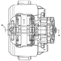
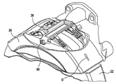
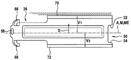
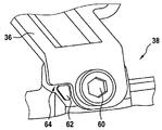
첨부된 도면에 나타난 본 발명에 따른 캘리퍼 디스크 브레이크의 예시적인 실시예는 브레이크 디스크(도시되지 않음)를 포함하며, 브레이크 디스크의 회전 축은 A로 표시된다. 전방 주행에서의 회전 방향이 화살표 D로 표시된다. 브레이크는 브레이크 캘리퍼(20)와 백 플레이트 조립체(22)를 포함하며, 브레이크 캘리퍼는 프레임과 같이 브레이크 디스크(도시되지 않음)를 꽉 잡는다. 마찰 라이닝을 갖는 금속 백킹 플레이트를 포함하는 휠 림-측 브레이크 라이닝은 도면 부호 24로 표시되며, 마찰 라이닝을 갖는 금속 백킹 플레이트를 포함하는 작동-측 브레이크 라이닝은 도면 부호 26으로 표시되고, 그리고 압력 플레이트는 도면 부호 28로 표시된다. 명시된 요소는 힘 전달 요소이다. 이 요소들은 억제 스프링(30, 32 및 34)에 의하여 억제된다. 즉, 이 요소들은 반경 방향으로 프리-스트레스트(pre-stressed)된다. 이하에서 더 설명된 바와 같이, 브레이크 라이닝(26)과 압력 플레이트(28) 또한 접선 방향으로 프리-스트레스트된다. An exemplary embodiment of a caliper disc brake according to the present invention shown in the accompanying drawings includes a brake disc (not shown), and the rotational axis of the brake disc is denoted by A. The direction of rotation in the forward running is indicated by arrow D. The brake includes a
브레이크 디스크의 양 측 상에서 지지된 브레이크 라이닝의 끼워 맞춤/제거 기능을 수행하는 캘리퍼 개구에 걸쳐 연장된 억제 요크(36; hold-down yoke) 형태의 억제 장치는 억제 스프링(30, 32 및 34)을 억제하는 역할을 한다. 여기서, 억제 요크(36)는 억제 스프링(30, 32 및 34)의 반경 방향 프리-스트레스뿐만 아니라 억제 스프링(30, 32 및 34)의 접선 방향 프리-스트레스에 책임이 있다. 대조적으로, 접선적인 프리-스트레스가 아닌, 단지 반경 방향 프리-스트레스가 억제 스프링(30)과 브레이크 라이닝(24)에 작용한다. 그로 인하여, 브레이크의 작동에 유해한 그리고 슬라이딩 캘리퍼의 자유로운 슬라이딩에 영향을 미치는, 억제 스프링(30)과 브레이크 라이닝(24)의 접선적인 프리-스트레스에서 시작된 모먼트가 방지된다. A suppression device in the form of a hold-down yoke (36) extending over a caliper opening that performs a fitting / removing function of the brake lining supported on both sides of the brake disk, . Here, the
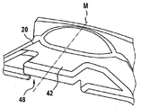
도면에 나타난 예시적인 실시예에서 슬라이딩 캘리퍼인 브레이크 캘리퍼(20)는 억제 요크(36)를 유지 및 지지하기 위한 유지 장치를 포함한다. 이 유지 장치는 2개의 영역, 즉 휠 림 측 영역(38)과 작동 측 영역(40)을 포함한다. 평면도에서, 양 영역은 회전축(A)에 평행하게 놓여진 중심선(M)을 중심으로 대칭적으로 형성된다. 이 영역들은 또한 반경 방향 중심 평면(ME)에 대하여 대칭적이며, 이 평면은 회전축(A)과 중심선(M)에 의하여 지속된다. 이 대칭은 유지 장치의 윤곽부가 캘리퍼가 좌측 브레이크 또는 우측 브레이크를 위하여 설계되었는지 여부에 관계없이 캘리퍼를 주조하기 위하여 하나의 그리고 동일한 몰드가 사용될 수 있는 정도인 것을 의미한다. In the exemplary embodiment shown in the drawings, the
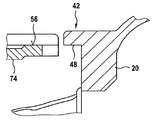
유지 장치의 작동 측 영역(40)의 형성 부분은 루프 에지형 구조의 돌출부(42)이다. 그 측면 플랭크(44, 46)는 접선 방향 힘을 흡수하는 역할을 한다. 그의 반경 방향의 내측 플랭크(48)는 반경 방향 힘을 흡수하는 역할을 한다. The forming portion of the
작동 측 상에서, 억제 요크(36)는 돌출부(42)에 맞추도록 구성된다. 예를 들어, 억제 요크는 요부(50)를 포함하며, 이 요부는 조립 상태에서 돌출부(42)를 수용한다. 여기서, 요부(50)의 측면 플랭크(52 및 54)는 접선 방향 힘을 전달하는 역할을 한다. 반경 방향적인 외부 표면(56)은 반경 방향 힘을 전달하는 역할을 한다. 맞추어진 상태에서, 외부 표면은 브레이크 디스크를 향하는 돌출부(42)의 플랭크(48)에 받쳐있다. On the operating side, the
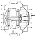
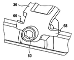
휠 림 측 영역(38)에서, 캘리퍼(20)는 나선형 구멍(58)을 포함하며, 억제 요크(36)를 고정하기 위하여 볼트(60)가 이 구멍 내로 나사 고정된다. 작동 측 영역(40)과 동일하게, 유지 장치의 휠 림 측 영역(38)은 중심선(M)과 중심 평면(ME)에 대하여 대칭적으로 구성된다. 억제 요크가 오른쪽 (왼쪽) 브레이크가 왼쪽 (오른쪽) 브레이크에 맞추어지는 것을 방지하기 위하여, 나선형 구멍(58)만이 대칭적으로 위치되지 않는다. 이는 주조에 의하여 형성되는 것이 아니라, 캘리퍼의 실제 주조 후에 드릴 및/또는 나선형 커터에 의하여 이루어진다. In the wheel
유지 장치의 영역(38) 내에 코딩 장치가 제공된다. 이 목적을 위하여, 도 11 및 도 12에 따르면, 가공 동안에 돌출부(62)는 남겨질 수 있으며, 따라서 도 12에 따라서 돌출부(62)와 맞추어진 개구(64)를 갖는 하나의 이러한 억제 요크(36)만이 끼워 맞추어질 수 있다. 나선형 개구(58)와 마찬가지로, 돌출부(62)는 주조에 의하여 형성되지 않으며 그리고 따라서 비대칭적으로 배치될 수 있다. A coding device is provided in the
부가적으로 또는 대안적으로, 도 13에 따른 억제 요크(36)는 러그를 포함할 수 있으며, 이 러그는 캘리퍼(20) 상에서 대응하는 구조체를 꽉 잡는다. 이는 단지 하나의 맞는 억제 요크(36)가 끼워맞추어질 수 있다는 것을 다시 한번 보장한다. Additionally or alternatively, the restraining
따라서, 돌출부(62), 개구(64) 그리고 러그(66 및 68)는 코딩 장치(coding device)이며, 이는 단지 하나의 맞는 억제 요크가 캘리퍼에 언제나 맞추어 진다는 것을 보장한다. Thus, the
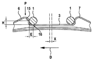
억제 요크는 2개의 다른 점에 있어서 비대칭이다. 먼저, 억제 요크는 휠 림 측 상이 아닌 작동 측 상의 접선적인 숄더(70 및 72)를 포함한다. 두 번째로, 중심선(M)에서 접선 방향으로 측정된 그의 치수(V1, V2)는 돌출부(72)의 영역 내, 즉 디스크 런-인 측 상에서보다는 제 1 돌출부(70)의 영역 내, 즉 디스크 런-아웃 상에서 더 크다. The suppression yoke is asymmetric at two different points. First, the containment yoke includes
브레이크 캘리퍼(20)가 억제 요크(36)를 위하여 유지 장치의 영역(38 및 40) 내에 대응적으로 비대칭적인 구조를 가질 필요 없이 그리고 휠 림 측 브레이크 라이닝(24) 상에 작용하는 불리한 프리-스트레스 없이 이 구성은 작동 측 상에 위치된 작동 측 브레이크 라이닝(26)과 압력 플레이트(28) 상에 접선적 프리-스트레스를 부여하는 것을 가능하게 한다. The
다른 스프링 프리-스트레스를 가함에 의하여 억제 스프링과의 다양한 상호 작용을 고의적으로 제어하는 것 또한 용이하게 가능하다. 도 7에 따라서 디스크 런-아웃에 대하여 점선의 방향으로 억제 요크의 폭(V1)을 조정하는 것만이 필요하다는 점에서 이는 수행될 수 있다. 이 목적을 위하여 따라서 시트 금속 프레싱을 형성하는 것만이 필요하다. 위에서 언급된 코딩과의 상호 작용을 통하여, 이를 이루기 위해 브레이크 캘리퍼의 주조 영역에 대하여 조정을 하지 않고서도 브레이크에 대한 정밀한 배치 그리고 그의 사용 조건을 이루는 것이 그후 가능하다. It is also readily possible to deliberately control the various interactions with the restraining spring by applying other spring-free stresses. This can be done in that only the adjustment of the width V1 of the suppression yoke in the direction of the dotted line is required for disk run-out according to Fig. For this purpose, therefore, it is only necessary to form the sheet metal pressing. Through interaction with the above-mentioned coding, it is then possible to achieve precise placement of the brakes and their conditions of use without making any adjustments to the casting area of the brake caliper.
억제 요크(36)는 바람직하게는 형상화된 시트-금속 프레싱으로서 생산되며 그리고 비드를 포함한다. 규격(V1과 V2) 간의 차이에 따라 이 비드는 중심선(M)과 반경 방향 평면(R)에 관하여 오프셋된다. 비드는 도면 부호 74로 표시된다. 조립된 상태에서, 비드는 확실하게 각 억제 스프링(32 및 34)에 받쳐 있으며 그리고 반경 방향 프리-스트레싱을 주는 역할을 수행한다 (도 19 참조). 대조적으로, 선행 기술에 대응하는 도 20에 따른 구성에서, 단지 선형 지지 접촉만이 존재한다. 이러한 선형 지지 접촉은 도 19에 따른 평평한 지지 접촉보다도 분명하게 억제 스프링에 현저하게 더 큰 부하를 부과한다.The
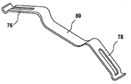
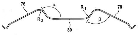
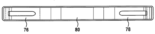
리프 스프링 형태의 억제 스프링의 설계 구성이 특히 도 14 내지 도 18로부터 추정될 수 있다. 억제 스프링은 2개의 동일한 스프링 레그(76, 78) 그리고 스프링 레그들 사이에 위치하고 반경 방향적으로 내측으로 돌출된 사다리꼴 중심 영역(80)을 포함한다. 이완된 상태에서 사다리꼴 영역(80)의 2개의 레그 각각은 그 베이스와 95° 이상의 각도(α)를 이룬다. 도면에 나타나 있는 예시적인 실시예에서, 이 각도는 117°이다. 레그는 2개의 인접한 스프링 레그(76, 78)와 85°보다 작은 각도(β)를 이룬다. 도시된 예시적인 실시예에서, 각도(β)는 74°이다. The design configuration of the leaf spring-type restraining spring can be in particular deduced from Fig. 14 to Fig. The restraining spring includes two identical spring legs (76, 78) and a trapezoidal central region (80) located between the spring legs and projecting radially inwardly. In the relaxed state, each of the two legs of the
측면도에서, 스프링은 각이진 형상이 아니다. 더 정확하게 말하면, 이완된 상태에서, 스프링 각각은 각 경우에 사다리꼴 영역(80)의 2개의 레그와 그 베이스 사이의 전이 영역 내에서 10㎜ 내지 16㎜, 도시된 예시적인 실시예에서 13㎜의 반경을 갖고 만곡져 있으며, 그리고 사다리꼴 영역(80)과 스프링 레그(76, 78) 사이의 전이 영역에서 스프링은 4㎜ 내지 9.5㎜, 도시된 예시적인 실시예에서 7㎜의 반경을 갖고 만곡져 있다. In the side view, the spring is not an angular shape. More precisely, in the relaxed state, each of the springs is in each
도 14 내지 도 16에 따라 스프링 레그(76, 78)는 직선형 구조일 수 있다. 그러나, 도 17 및 도 18에서 보여질 수 있는 바와 같이 스프링 레그는 오목 또는 볼록 구조일 수도 있다. 14 to 16, the
억제 스프링(32)에 받쳐진 돌출부(70)의 영역은 도 19에서 도면 부호 82로 표시된다. 그 중심(M82)은 중심(M74)에서 거리(H)만큼 반경 방향으로 분리되며 그리고 접선 방향으로 거리(E)만큼 분리된다. 여기서, H<E이다. 대조적으로, 도 20에서 비교하면 선행 기술에서의 대응하는 지지 접촉선(15 및 16)은 H=E관계로 배치된다. The area of the
도면에 나타나있는 예시적인 실시예에서, 가장 큰 (압축) 응력의 부위(P)는 억제 스프링(32) 내에 놓여지며 이 부위는 중심 영역(74)과 스프링 레그(76) 사이의 전이 영역에 위치하고 그리고 마찰로 인하여 또는 접촉 영역 내에서의 브레이크 라이닝 또는 압력 플레이트의 반경 방향 충격으로 인하여 가장 큰 마모의 (넓은) 영역과 관련이 없다. In the exemplary embodiment shown in the figures, the region P of the largest (compressive) stress is placed within the restraining
대조적으로, 유사한 사용 조건 하에서, 위에서 특정된 바와 같이, 도 20 내의 선행 기술에 따르면, 선형 지지 접촉만이 반경 방향 접촉 영역 내에서 발생한다. 따라서 여기에서는 선형 지지 접촉(화살표 참조)을 갖는 반경 방향 영역 내에서의 가장 큰 마모의 구역이 그후 억제 스프링 내의 가장 큰 (압축) 응력의 구역(P)에 직접적으로 그리고 밀접하게 인접하며 따라서 여기에서 H=E이다. In contrast, under similar use conditions, as specified above, according to the prior art in Figure 20, only linear support contacts occur within the radial contact area. The area of the greatest wear in the radial area with the linear supporting contact (see arrow) is then directly and closely adjacent to the zone P of the largest (compressive) stress in the restraining spring, H = E.
특히 도 19로부터 보여질 수 있는 바와 같이 횡단면도에서의 억제 요크(36)는 바깥 쪽에서, 즉 돌출부(70, 72)의 종단에서 경사진 홈통형(trough-like)의 구조를 갖는다. 이는 억제 스프링의 역 이동 동안에 약간의 상대 이동(슬라이딩)을 허용한다. 직교적인 스프링 부분에 받쳐있는 둥근 재료를 갖는 도 20에 따른 선행 기술에서는 이렇지 않다. 본 발명의 구조는 임계 영역에서의 응력 부하를 줄인다. 19, the restraining
또한 여기에서, 도 1에 따른 선행 기술에서와 같이, 억제 스프링은 브레이크 라이닝의 축 방향으로 브레이크 라이닝에 결합되며, 이는 브레이크 라이닝의 외측 에지의 반경 방향 숄더(12)가 스프링의 2개의 측면 스프링 레그 내의 길게 늘어진 개구(8, 9)를 통과하기 때문이다. 종단에서 스프링 레그가 브레이크 라이닝의 외측 에지의 다른 반경 방향 숄더(13)에 받쳐 있다. 억제 스프링은 리프 스프링으로서 구현된다. 1, the restraining spring is coupled to the brake lining in the axial direction of the brake lining, so that the
위의 설명, 청구범위 그리고 도면에 개시된 본 발명의 특징은 다양한 실시예에서 개별적으로 그리고 어떠한 조합 형태로 본 발명을 구현하는데 필수적일 수 있다. The above description, the claims, and the features of the invention disclosed in the drawings may be necessary to implement the invention individually and in any combination in various embodiments.
Claims (10)
브레이크 캘리퍼(20),
백 플레이트 조립체(22),
브레이크 캘리퍼 또는 백 플레이트 조립체의 채널 내에서 안내되고 그리고 지지되는, 브레이크 패드 플레이트(24, 26) 및/또는 압력 플레이트(28)와 같은 힘 전달 요소,
힘 전달 요소를 억제하기 위한 억제 스프링(30, 32, 34), 그리고
유지 장치(38, 40)에 의하여 캘리퍼 상에서 유지되고 그리고 지지되는 억제 장치(36)를 갖되,
억제 장치는 힘 전달 장치에 맞서 억제 스프링을 반경 방향으로 프리-스트레스시키고 그리고 힘 전달 장치에 맞서 억제 스프링을 전방 주행 회전 방향으로 접선적으로 프리-스트레스시키며, 여기서 유지 장치는 회전 축에 평행하게 놓여진 중심선(M)을 가지며, 접선 방향적 프리-스트레싱이 중심선(M)에서 접선 방향으로 측정된 억제 장치(36)의 크기(V1, V2)가 디스크 런-인 측 상에서보다 디스크-런 아웃 측 상에서 적어도 부분적으로 크다는 점에 적어도 부분적으로 원인이 되는 것을 특징으로 하는 차량, 특히 상용 차량의 캘리퍼 디스크 브레이크. A brake disk having a rotation axis A,
The brake caliper 20,
The backplate assembly 22,
Force transmission elements, such as brake pad plates 24 and 26 and / or pressure plate 28, which are guided and supported in the channels of the brake caliper or backplate assembly,
Restraining springs (30, 32, 34) for restraining a force transmitting element, and
And a restraining device (36) held and supported on the caliper by retaining devices (38, 40)
The restraining device pre-stresses the restraining spring against the force transmitting device and pre-stresses the restraining spring against the force transmitting device tangentially in the forward running rotational direction, wherein the retaining device is placed in parallel with the rotational axis central line (M) to have tangential directional pre-stressing the central line (M) measured in the tangential direction suppression device 36 of the size (V 1, V 2), the disk run-disk than on the side-run Out side of the caliper disc brake, particularly at least partially on the out side.
Applications Claiming Priority (3)
| Application Number | Priority Date | Filing Date | Title |
|---|---|---|---|
| DE102013008161.0A DE102013008161A1 (en) | 2013-05-13 | 2013-05-13 | Caliper disc brake of a vehicle, especially a commercial vehicle, and caliper of such a brake |
| DE102013008161.0 | 2013-05-13 | ||
| PCT/EP2014/001175 WO2014183839A1 (en) | 2013-05-13 | 2014-05-02 | Caliper disc brake of a vehicle, in particular of a commercial vehicle, and brake caliper of such a brake |
Publications (1)
| Publication Number | Publication Date |
|---|---|
| KR20160006749A true KR20160006749A (en) | 2016-01-19 |
Family
ID=50693609
Family Applications (1)
| Application Number | Title | Priority Date | Filing Date |
|---|---|---|---|
| KR1020157034942A KR20160006749A (en) | 2013-05-13 | 2014-05-02 | Caliper disc brake of a vehicle, in particular a commercial vehicle, and brake caliper of such a brake |
Country Status (10)
| Country | Link |
|---|---|
| US (1) | US9816575B2 (en) |
| EP (1) | EP2997279B1 (en) |
| JP (1) | JP6410268B2 (en) |
| KR (1) | KR20160006749A (en) |
| CN (1) | CN105229329B (en) |
| BR (1) | BR112015028615A2 (en) |
| DE (1) | DE102013008161A1 (en) |
| ES (1) | ES2689131T3 (en) |
| RU (1) | RU2657607C2 (en) |
| WO (1) | WO2014183839A1 (en) |
Families Citing this family (11)
| Publication number | Priority date | Publication date | Assignee | Title |
|---|---|---|---|---|
| DE102015114351B4 (en) * | 2015-08-28 | 2022-02-03 | Knorr-Bremse Systeme für Nutzfahrzeuge GmbH | Disc brake of a commercial vehicle |
| DE102015013240A1 (en) * | 2015-10-12 | 2017-04-13 | Wabco Europe Bvba | Disc brake, in particular for commercial vehicles |
| DE102015121942A1 (en) | 2015-12-16 | 2017-06-22 | Knorr-Bremse Systeme für Nutzfahrzeuge GmbH | Disc brake for a commercial vehicle and brake pad for a disc brake |
| DE102015122558A1 (en) * | 2015-12-22 | 2017-06-22 | Bpw Bergische Achsen Kg | Disc brake and hold-down for attaching brake pads in a disc brake |
| DE102015122569A1 (en) | 2015-12-22 | 2017-06-22 | Bpw Bergische Achsen Kg | Disc brake, brake pad for a disc brake, hold-down for attaching brake pads |
| DE102016100623A1 (en) * | 2016-01-15 | 2017-07-20 | Bpw Bergische Achsen Kg | Brake pad holder of a vehicle disc brake and hold-down for the attachment of brake pads |
| IT201600130800A1 (en) * | 2016-12-23 | 2018-06-23 | Freni Brembo Spa | Spring device for disc brake, pad and spring assembly and brake caliper |
| KR102589051B1 (en) * | 2017-12-12 | 2023-10-13 | 현대모비스 주식회사 | Caliper apparatus |
| JP7084174B2 (en) | 2018-03-27 | 2022-06-14 | 曙ブレーキ工業株式会社 | Floating disc brake |
| US11708875B2 (en) * | 2018-05-23 | 2023-07-25 | Zf Cv Systems Europe Bv | Directional arrow on a brake carrier |
| DE102019209529B4 (en) * | 2019-06-28 | 2021-05-06 | Continental Teves Ag & Co. Ohg | Multi-disc brake for a rotatable element |
Family Cites Families (26)
| Publication number | Priority date | Publication date | Assignee | Title |
|---|---|---|---|---|
| DE3762149D1 (en) * | 1986-01-17 | 1990-05-10 | Lucas Ind Plc | FLOATING SADDLE PART COVER DISC BRAKE. |
| DE3910154C2 (en) | 1989-03-29 | 1998-07-02 | Perrot Bremse Gmbh Deutsche | Leaf spring arrangement for holding down the brake pad carrier in a disc brake |
| DE4426603A1 (en) | 1994-07-27 | 1996-02-01 | Perrot Bremsen Gmbh | Device for holding a brake pad in a disc brake |
| DE19626299A1 (en) | 1996-07-01 | 1998-01-08 | Teves Gmbh Alfred | Spring arrangement for a floating caliper disc brake |
| DE102005044091A1 (en) * | 2005-09-15 | 2007-04-05 | Knorr-Bremse Systeme für Nutzfahrzeuge GmbH | Disc brake, in particular for a commercial vehicle |
| DE102005045877B3 (en) | 2005-09-26 | 2007-02-15 | Knorr-Bremse Systeme für Nutzfahrzeuge GmbH | Disk brake for commercial vehicle, has mounting bracket that extends in axial direction of disk, is spring loaded in longitudinal axial direction and lies in form fit retainer, and spring that is supported at mounting bracket |
| DE102006051965A1 (en) | 2005-11-03 | 2007-05-16 | Knorr Bremse Systeme | Disc brake lining assembly for road vehicle, has brake linings that are located on either side of brake caliper, where brake linings and lining retaining bracket form mounting assembly |
| DE102006023964B3 (en) * | 2006-05-22 | 2007-08-02 | Wabco Radbremsen Gmbh | Disc brake especially for utility vehicle has an axial tag on the thrust system to limit the release spring travel |
| DE102007019429B4 (en) | 2007-04-25 | 2009-01-02 | Knorr-Bremse Systeme für Nutzfahrzeuge GmbH | Disc brake, in particular for a commercial vehicle |
| DE102007036353B3 (en) | 2007-08-02 | 2009-02-26 | Wabco Radbremsen Gmbh | Disc brake, in particular for commercial vehicles, as well as hold-down spring such a disc brake |
| DE102007046945B4 (en) * | 2007-10-01 | 2009-07-16 | Knorr-Bremse Systeme für Nutzfahrzeuge GmbH | Brake pad holder and brake pad of a disc brake |
| JP5156325B2 (en) * | 2007-10-11 | 2013-03-06 | カヤバ工業株式会社 | Caliper brake device for vehicle |
| DE102007049979A1 (en) * | 2007-10-18 | 2009-04-23 | Knorr-Bremse Systeme für Nutzfahrzeuge GmbH | Brake pad holder of a disc brake and brake pad |
| DE102007049981B4 (en) * | 2007-10-18 | 2009-07-30 | Knorr-Bremse Systeme für Nutzfahrzeuge GmbH | Brake pad of a disc brake |
| WO2009092525A1 (en) * | 2008-01-22 | 2009-07-30 | Knorr-Bremse Systeme für Nutzfahrzeuge GmbH | Disk brake |
| DE102008027052A1 (en) | 2008-06-06 | 2009-12-24 | Knorr-Bremse Systeme für Nutzfahrzeuge GmbH | Disk brake for commercial motor vehicle, has brake caliper and brake disk connected with brake lining, where brake caliper is overlapped on brake disk and fastened to stationary brake carrier |
| US8215458B2 (en) * | 2008-11-07 | 2012-07-10 | Knorr-Bremse Systeme Fuer Nutzfahrzeuge Gmbh | Fixedly connected pad retaining spring for a brake pad |
| DE102008058265A1 (en) * | 2008-11-20 | 2010-05-27 | Lucas Automotive Gmbh | Disc brake and brake pad assembly for this |
| DE102009030414B4 (en) | 2009-06-25 | 2013-01-17 | Knorr-Bremse Systeme für Nutzfahrzeuge GmbH | Brake pad for a disc brake |
| DE102011115304B3 (en) * | 2011-09-29 | 2013-02-07 | Wabco Radbremsen Gmbh | Disc brake, in particular for commercial vehicles, as well as hold-down spring such a disc brake |
| DE102012109783A1 (en) | 2012-10-15 | 2014-04-17 | Knorr-Bremse Systeme für Nutzfahrzeuge GmbH | Arrangement of a pad retaining bracket on the caliper of a disc brake |
| DE102012023813A1 (en) | 2012-12-05 | 2014-06-05 | Wabco Radbremsen Gmbh | Disc brake, in particular for commercial vehicles, as well as hold-down spring such a disc brake |
| DE102013008160A1 (en) | 2013-05-13 | 2014-11-13 | Wabco Europe Bvba | Caliper disc brake of a vehicle, in particular a commercial vehicle, and hold-down spring such a brake |
| DE102013008155A1 (en) | 2013-05-13 | 2014-11-13 | Wabco Europe Bvba | Caliper disc brake of a vehicle, in particular a commercial vehicle, and hold-down device such a brake |
| DE102013012547B4 (en) | 2013-07-29 | 2021-08-19 | Wabco Europe Bvba | Disc brakes, in particular for commercial vehicles, and brake linings for such a disc brake |
| DE102013015002A1 (en) | 2013-09-10 | 2015-03-12 | Wabco Europe Bvba | Disc brake, in particular for commercial vehicles |
-
2013
- 2013-05-13 DE DE102013008161.0A patent/DE102013008161A1/en not_active Withdrawn
-
2014
- 2014-05-02 US US14/787,655 patent/US9816575B2/en active Active
- 2014-05-02 BR BR112015028615A patent/BR112015028615A2/en not_active Application Discontinuation
- 2014-05-02 JP JP2016513246A patent/JP6410268B2/en not_active Expired - Fee Related
- 2014-05-02 KR KR1020157034942A patent/KR20160006749A/en active IP Right Grant
- 2014-05-02 CN CN201480026608.XA patent/CN105229329B/en not_active Expired - Fee Related
- 2014-05-02 EP EP14723328.2A patent/EP2997279B1/en active Active
- 2014-05-02 WO PCT/EP2014/001175 patent/WO2014183839A1/en active Application Filing
- 2014-05-02 ES ES14723328.2T patent/ES2689131T3/en active Active
- 2014-05-02 RU RU2015144859A patent/RU2657607C2/en active
Also Published As
| Publication number | Publication date |
|---|---|
| DE102013008161A1 (en) | 2014-11-13 |
| US9816575B2 (en) | 2017-11-14 |
| BR112015028615A2 (en) | 2017-07-25 |
| CN105229329B (en) | 2018-12-04 |
| RU2657607C2 (en) | 2018-06-14 |
| EP2997279B1 (en) | 2018-08-01 |
| CN105229329A (en) | 2016-01-06 |
| US20160169307A1 (en) | 2016-06-16 |
| EP2997279A1 (en) | 2016-03-23 |
| JP2016519266A (en) | 2016-06-30 |
| WO2014183839A1 (en) | 2014-11-20 |
| RU2015144859A (en) | 2017-06-19 |
| ES2689131T3 (en) | 2018-11-08 |
| RU2015144859A3 (en) | 2018-03-22 |
| JP6410268B2 (en) | 2018-10-24 |
Similar Documents
| Publication | Publication Date | Title |
|---|---|---|
| KR20160006749A (en) | Caliper disc brake of a vehicle, in particular a commercial vehicle, and brake caliper of such a brake | |
| KR102218145B1 (en) | Caliper disc brake of a vehicle, in particular a commercial vehicle, and holding-down device of such a brake | |
| KR102181362B1 (en) | Caliper disc brake of a vehicle, in particular a commercial vehicle, and holding-down spring of such a brake | |
| US10119581B2 (en) | Disc brake | |
| EP2646705B1 (en) | Brake rotor | |
| JP4698147B2 (en) | Disc brake assembly | |
| CN110709621B (en) | Disk brake, brake caliper of a disk brake, and pressure piece and leaf spring for fixing a brake lining of a disk brake | |
| CN108603547B (en) | Disk brake, brake lining for a disk brake, and holding-down element for fastening a brake lining | |
| EP3810953B1 (en) | Spring for friction pads in a disc brake caliper | |
| KR20150121075A (en) | Disc brake assembly with non-rotatable vehicle component and method for producing same | |
| US10801569B2 (en) | Disc brake | |
| US10890224B2 (en) | Brake lining for a disc brake, disc-brake hold-down for brake linings of a disc brake | |
| EP3810954B1 (en) | Spring for friction pads in a disc brake caliper | |
| WO2003029684A1 (en) | Sliding disc braking system | |
| EP1780437B1 (en) | Flat spring for brake pads used in disc brakes, in particular for industrial vehicles | |
| JP4319046B2 (en) | Motorcycle brake equipment |
Legal Events
| Date | Code | Title | Description |
|---|---|---|---|
| E902 | Notification of reason for refusal | ||
| E701 | Decision to grant or registration of patent right |