KR20160003586U - A drain connection for washstand - Google Patents
A drain connection for washstand Download PDFInfo
- Publication number
- KR20160003586U KR20160003586U KR2020150002235U KR20150002235U KR20160003586U KR 20160003586 U KR20160003586 U KR 20160003586U KR 2020150002235 U KR2020150002235 U KR 2020150002235U KR 20150002235 U KR20150002235 U KR 20150002235U KR 20160003586 U KR20160003586 U KR 20160003586U
- Authority
- KR
- South Korea
- Prior art keywords
- pipe
- hole
- drain
- connection
- drain pipe
- Prior art date
Links
Images

Classifications
-
- E—FIXED CONSTRUCTIONS
- E03—WATER SUPPLY; SEWERAGE
- E03C—DOMESTIC PLUMBING INSTALLATIONS FOR FRESH WATER OR WASTE WATER; SINKS
- E03C1/00—Domestic plumbing installations for fresh water or waste water; Sinks
- E03C1/12—Plumbing installations for waste water; Basins or fountains connected thereto; Sinks
- E03C1/14—Wash-basins connected to the waste-pipe
-
- E—FIXED CONSTRUCTIONS
- E03—WATER SUPPLY; SEWERAGE
- E03C—DOMESTIC PLUMBING INSTALLATIONS FOR FRESH WATER OR WASTE WATER; SINKS
- E03C1/00—Domestic plumbing installations for fresh water or waste water; Sinks
- E03C1/12—Plumbing installations for waste water; Basins or fountains connected thereto; Sinks
- E03C1/22—Outlet devices mounted in basins, baths, or sinks
Abstract
More particularly, the present invention relates to a connection pipe for a drainage pipe for a washstand, and more particularly to a drain pipe connecting a drain pipe and a drain trap for transferring water to a sewage pipe, The drainage pipe connection pipe for the washstand which can prevent water leakage during backflow is a drainage pipe connection pipe for connecting the drainage pipe for transferring the water dewatered to the drainage pipe to the drainage pipe and the drainage trap for connection to the drainage pipe, The upper connection hole is formed with an insertion groove, and the upper end of the insertion hole is formed with a C-shaped protrusion, and a center hole is formed with a through hole to allow the drain pipe to be inserted therein. .
Description
More particularly, the present invention relates to a connection pipe for a drainage pipe for a washstand, and more particularly to a drain pipe connecting a drain pipe and a drain trap for transferring water to a sewage pipe, The present invention relates to a drainage pipe connector for a washstand that can be easily replaced and can prevent leakage during backflow.
Generally, a sink is installed in a bathroom of a guest room such as a home or a hotel, and a toilet in a public place, and is used to put water in the sink to hand or wash water.
In order to prevent the inflow of odor and insects, there is a drain trap installed and fixed between the drain pipe of the washstand side and the drain pipe of the sewage pipe by using a nut do.
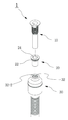
As shown in Fig. 1, the drain trap connected to the drain pipe of the conventional washstand is adjusted in height by the power provided by the drive unit 2, and the height of the
As described above, since the connecting end portion for screw connection to the conventional washstand drain is formed at the upper side and fastened, quick fastening is not easy, and there is a problem that water leakage may occur in the reverse flow.
The object of the present invention is to solve the above problems, and it is an object of the present invention to provide a drainage pipe and a drainage trap which are connected to a sewer pipe, And it is an object of the present invention to provide a drain pipe connector for a washstand which can be easily replaced at the time of breakage and can prevent leakage during backflow.
According to an aspect of the present invention, there is provided a drainage pipe connection pipe for connecting a drain pipe and a drainage trap, the water drainage pipe being connected to a drain pipe, Wherein a U-shaped protrusion is formed on an upper outer circumferential surface of the drain trap so that the insertion groove of the drain trap is inserted and coupled, and a connecting hole having a through hole is formed in the center of the drain hole so that the drain pipe can be inserted therein. do.
In addition, an elastic member is provided on the U-shaped protrusion of the connector.
Further, the through-hole portion of the connector is formed with a predetermined inclined surface.
In addition, the inside of the through hole of the connector is formed as a through hole having a predetermined inclined surface.
In addition, a plurality of stepped portions are formed on the inclined surface formed inside the through-hole of the connector.
As described above, the drain pipe connection port of the present invention connects the drain pipe and the drain trap so that the drain pipe is tightly coupled to the through hole of the connection pipe in a non-tight fitting manner by a rotary method. And the through hole of the connection port is tightly coupled to the outer surface of the drain pipe to further prevent leakage of water.
BRIEF DESCRIPTION OF THE DRAWINGS FIG. 1 is a cross-sectional view of a conventional drainage trap structure for a height-adjustable washstand. FIG.
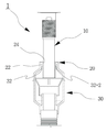
2 is an exploded perspective view showing a drain pipe connection port for a washstand in the present invention;
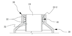
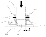
Fig. 3 is an assembled cross-sectional view showing a drain pipe connector of the present invention. Fig.
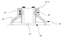
4A is a view showing another embodiment of the drain pipe connector of the present invention.
Figure 4b is an embodiment of Figure 4a.
5 is a view showing another embodiment of the connector of the present invention.
6 is another embodiment showing a connector of the present invention.
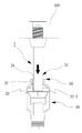
Fig. 7 is a use example showing a drain pipe connector of the present invention. Fig.
Hereinafter, preferred embodiments of the present invention will be described in more detail with reference to the accompanying drawings. Prior to this, terms and words used in the present specification and claims should not be construed as limited to ordinary or dictionary meanings, and the inventor may appropriately design the concept of the term appropriately to describe its own invention in the best way. It should be interpreted as a meaning and a concept consistent with the technical idea of the present invention based on the principle that it can be defined.
Therefore, the embodiments described in the present specification and the constitutions shown in the drawings are merely the most preferred embodiments of the present invention and do not represent all the technical ideas of the present invention. Therefore, various equivalents It should be understood that water and variations may be present.
As shown in FIGS. 2 to 3, the drain
The
4A, the
4B, an
The
The
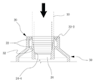
As shown in FIG. 5, the inner surface of the
That is, the
As shown in FIG. 6, the through
That is, the
As described above, the drain
The
1: Sink drain pipe connector
10: Water pipe
20: Connector 22: C-shaped projection
24: Through hole 24-2:
24-4:
30: drain trap 32: connection through hole
32-2:
40: elastic member
Claims (4)
The drain trap is formed with an insertion groove formed in the upper connection hole and an insertion groove of the drain trap. The upper end of the drain trap is formed with a C-shaped protrusion. The center hole is formed with a through- And a drain pipe connected to the drain pipe.
Wherein a U-shaped projection of the connector is provided with an elastic member.
And the inner side of the through hole of the connection port is formed as a through hole having a predetermined inclined surface.
Wherein a plurality of stepped portions are formed on an inclined surface formed inside the through-hole of the connection port.
Priority Applications (1)
| Application Number | Priority Date | Filing Date | Title |
|---|---|---|---|
| KR2020150002235U KR20160003586U (en) | 2015-04-08 | 2015-04-08 | A drain connection for washstand |
Applications Claiming Priority (1)
| Application Number | Priority Date | Filing Date | Title |
|---|---|---|---|
| KR2020150002235U KR20160003586U (en) | 2015-04-08 | 2015-04-08 | A drain connection for washstand |
Publications (1)
| Publication Number | Publication Date |
|---|---|
| KR20160003586U true KR20160003586U (en) | 2016-10-18 |
Family
ID=57234202
Family Applications (1)
| Application Number | Title | Priority Date | Filing Date |
|---|---|---|---|
| KR2020150002235U KR20160003586U (en) | 2015-04-08 | 2015-04-08 | A drain connection for washstand |
Country Status (1)
| Country | Link |
|---|---|
| KR (1) | KR20160003586U (en) |
Cited By (2)
| Publication number | Priority date | Publication date | Assignee | Title |
|---|---|---|---|---|
| KR200488311Y1 (en) * | 2018-06-22 | 2019-01-11 | 주식회사 에스엠지 | The sink trap |
| KR20200127519A (en) * | 2019-05-02 | 2020-11-11 | 주식회사 아이비코리아 | Drain trap assembly |
Citations (1)
| Publication number | Priority date | Publication date | Assignee | Title |
|---|---|---|---|---|
| KR100296030B1 (en) | 1999-05-15 | 2001-07-12 | 윤종용 | Receiving apparatus in cdma type wireless telephone set and method thereof |
-
2015
- 2015-04-08 KR KR2020150002235U patent/KR20160003586U/en not_active Application Discontinuation
Patent Citations (1)
| Publication number | Priority date | Publication date | Assignee | Title |
|---|---|---|---|---|
| KR100296030B1 (en) | 1999-05-15 | 2001-07-12 | 윤종용 | Receiving apparatus in cdma type wireless telephone set and method thereof |
Cited By (2)
| Publication number | Priority date | Publication date | Assignee | Title |
|---|---|---|---|---|
| KR200488311Y1 (en) * | 2018-06-22 | 2019-01-11 | 주식회사 에스엠지 | The sink trap |
| KR20200127519A (en) * | 2019-05-02 | 2020-11-11 | 주식회사 아이비코리아 | Drain trap assembly |
Similar Documents
| Publication | Publication Date | Title |
|---|---|---|
| KR200395156Y1 (en) | Drain apparatus for bathtub | |
| KR20160003586U (en) | A drain connection for washstand | |
| KR101971165B1 (en) | Installation structure for trap of toilet | |
| JP5651830B2 (en) | Connection structure between tank and drainage | |
| KR20100121385A (en) | Drain-outlet cork | |
| KR101371894B1 (en) | Drainpipe for washbasin | |
| KR200458962Y1 (en) | Trap for Washstand | |
| KR101674159B1 (en) | Bathtub a drainage system | |
| KR200480200Y1 (en) | The drain for pop-up valve of a washbowl | |
| KR101594899B1 (en) | A draining trap apparatus for a washstand | |
| KR101186776B1 (en) | The washstand drainage device which possessed a globe fixed a conduit pipe | |
| JP2007138654A (en) | Drain trap | |
| KR20100011172U (en) | Drainage unit | |
| KR101208089B1 (en) | Connecting structure for Multiple trap | |
| KR200464474Y1 (en) | An apparatus for blocking offensive odor from waste pipe drain | |
| KR101361120B1 (en) | An apparatus for blocking offensive odor from waste pipe drain | |
| KR101177490B1 (en) | Piping connection structure of multiple trap | |
| KR101900205B1 (en) | Sewage with counterflow preventing cap | |
| KR200243741Y1 (en) | The drain tank for building | |
| JP3202968U (en) | Water tank with effective capacity water level adjustment pipe | |
| RU2017108641A (en) | BATHROOM KIT | |
| KR20170048718A (en) | Minor Elevation Flow Drain on Foor | |
| TWM456389U (en) | Down pipe structure | |
| KR101763828B1 (en) | Lavatory faucet connector | |
| WO2020025602A1 (en) | Drain system |
Legal Events
| Date | Code | Title | Description |
|---|---|---|---|
| A201 | Request for examination | ||
| E902 | Notification of reason for refusal | ||
| E601 | Decision to refuse application |