KR20150143329A - Method for magnetic resonance imaging - Google Patents
Method for magnetic resonance imaging Download PDFInfo
- Publication number
- KR20150143329A KR20150143329A KR1020150081703A KR20150081703A KR20150143329A KR 20150143329 A KR20150143329 A KR 20150143329A KR 1020150081703 A KR1020150081703 A KR 1020150081703A KR 20150081703 A KR20150081703 A KR 20150081703A KR 20150143329 A KR20150143329 A KR 20150143329A
- Authority
- KR
- South Korea
- Prior art keywords
- magnetic resonance
- image data
- map
- subject
- resonance image
- Prior art date
Links
Images


Classifications
-
- G—PHYSICS
- G01—MEASURING; TESTING
- G01R—MEASURING ELECTRIC VARIABLES; MEASURING MAGNETIC VARIABLES
- G01R33/00—Arrangements or instruments for measuring magnetic variables
- G01R33/20—Arrangements or instruments for measuring magnetic variables involving magnetic resonance
- G01R33/28—Details of apparatus provided for in groups G01R33/44 - G01R33/64
- G01R33/38—Systems for generation, homogenisation or stabilisation of the main or gradient magnetic field
- G01R33/387—Compensation of inhomogeneities
- G01R33/3875—Compensation of inhomogeneities using correction coil assemblies, e.g. active shimming
-
- A—HUMAN NECESSITIES
- A61—MEDICAL OR VETERINARY SCIENCE; HYGIENE
- A61B—DIAGNOSIS; SURGERY; IDENTIFICATION
- A61B5/00—Measuring for diagnostic purposes; Identification of persons
- A61B5/05—Detecting, measuring or recording for diagnosis by means of electric currents or magnetic fields; Measuring using microwaves or radio waves
- A61B5/055—Detecting, measuring or recording for diagnosis by means of electric currents or magnetic fields; Measuring using microwaves or radio waves involving electronic [EMR] or nuclear [NMR] magnetic resonance, e.g. magnetic resonance imaging
-
- G—PHYSICS
- G01—MEASURING; TESTING
- G01R—MEASURING ELECTRIC VARIABLES; MEASURING MAGNETIC VARIABLES
- G01R33/00—Arrangements or instruments for measuring magnetic variables
- G01R33/20—Arrangements or instruments for measuring magnetic variables involving magnetic resonance
-
- G—PHYSICS
- G01—MEASURING; TESTING
- G01R—MEASURING ELECTRIC VARIABLES; MEASURING MAGNETIC VARIABLES
- G01R33/00—Arrangements or instruments for measuring magnetic variables
- G01R33/20—Arrangements or instruments for measuring magnetic variables involving magnetic resonance
- G01R33/24—Arrangements or instruments for measuring magnetic variables involving magnetic resonance for measuring direction or magnitude of magnetic fields or magnetic flux
- G01R33/243—Spatial mapping of the polarizing magnetic field
-
- G—PHYSICS
- G01—MEASURING; TESTING
- G01R—MEASURING ELECTRIC VARIABLES; MEASURING MAGNETIC VARIABLES
- G01R33/00—Arrangements or instruments for measuring magnetic variables
- G01R33/20—Arrangements or instruments for measuring magnetic variables involving magnetic resonance
- G01R33/44—Arrangements or instruments for measuring magnetic variables involving magnetic resonance using nuclear magnetic resonance [NMR]
- G01R33/48—NMR imaging systems
- G01R33/4828—Resolving the MR signals of different chemical species, e.g. water-fat imaging
-
- G—PHYSICS
- G01—MEASURING; TESTING
- G01R—MEASURING ELECTRIC VARIABLES; MEASURING MAGNETIC VARIABLES
- G01R33/00—Arrangements or instruments for measuring magnetic variables
- G01R33/20—Arrangements or instruments for measuring magnetic variables involving magnetic resonance
- G01R33/44—Arrangements or instruments for measuring magnetic variables involving magnetic resonance using nuclear magnetic resonance [NMR]
- G01R33/48—NMR imaging systems
- G01R33/54—Signal processing systems, e.g. using pulse sequences ; Generation or control of pulse sequences; Operator console
- G01R33/56—Image enhancement or correction, e.g. subtraction or averaging techniques, e.g. improvement of signal-to-noise ratio and resolution
- G01R33/565—Correction of image distortions, e.g. due to magnetic field inhomogeneities
- G01R33/56536—Correction of image distortions, e.g. due to magnetic field inhomogeneities due to magnetic susceptibility variations
Landscapes
- Physics & Mathematics (AREA)
- Condensed Matter Physics & Semiconductors (AREA)
- General Physics & Mathematics (AREA)
- Health & Medical Sciences (AREA)
- Magnetic Resonance Imaging Apparatus (AREA)
- High Energy & Nuclear Physics (AREA)
- Nuclear Medicine, Radiotherapy & Molecular Imaging (AREA)
- Life Sciences & Earth Sciences (AREA)
- Engineering & Computer Science (AREA)
- Radiology & Medical Imaging (AREA)
- General Health & Medical Sciences (AREA)
- Pathology (AREA)
- Biomedical Technology (AREA)
- Heart & Thoracic Surgery (AREA)
- Medical Informatics (AREA)
- Molecular Biology (AREA)
- Surgery (AREA)
- Animal Behavior & Ethology (AREA)
- Biophysics (AREA)
- Public Health (AREA)
- Veterinary Medicine (AREA)
- Signal Processing (AREA)
Abstract
Description
본 발명은 자기 공명 영상화 방법 및 자기 공명 장치에 관한 것이다.The present invention relates to a magnetic resonance imaging method and a magnetic resonance apparatus.
자기 공명 단층 촬영 시스템으로도 불리는 자기 공명 장치에서는 통상적으로 피검자, 특히 환자의 검사 받을 몸이 주자석(main magnetic)에 의해서 예를 들어 1.5 또는 3 또는 7 테슬라(tesla)의 상대적으로 높은 주자장(main magnetic field)에 노출된다. 추가로, 경사 코일 유닛에 의해서 경사 펄스가 인가된다. 이 경우에는, 고주파 안테나 유닛을 통해 적합한 안테나 장치에 의해서 고주파수의 고주파 펄스, 특히 여기 펄스(excitation pulse)가 발송되며, 이와 같은 상황은, 이 고주파 펄스에 의해 공명으로 여기된 특정 원자의 핵 스핀이 주자장의 자력선(magnetic field line)에 대해 규정된 플립 각도(flip angle)만큼 기울어지는 효과를 낳는다. 핵 스핀의 이완시에는 고주파 신호, 소위 자기 공명 신호가 방출되고, 이 자기 공명 신호는 적합한 고주파 안테나에 의해서 수신된 다음에 추가 가공된다. 결국, 이와 같이 획득된 미가공 데이터(raw data)로부터는 원하는 화상 데이터(image data)가 재구성될 수 있다.Magnetic resonance imaging systems, also referred to as magnetic resonance tomography systems, are typically used to measure the body of a subject, especially a patient, by a main magnetic body, for example, a relatively high magnetic field of 1.5 or 3 or 7 tesla magnetic field. In addition, a warp pulse is applied by the warp coil unit. In this case, a high-frequency high-frequency pulse, in particular an excitation pulse, is sent by a suitable antenna device through the high-frequency antenna unit, Resulting in a tilting effect by a defined flip angle relative to the magnetic field line of the magnetic field. When the nuclear spin relaxes, a high frequency signal, a so-called magnetic resonance signal, is emitted which is further processed after being received by a suitable high frequency antenna. As a result, the desired image data can be reconstructed from the raw data thus obtained.
특정한 측정을 위해서는, 펄스 시퀀스(pulse sequence)로도 불리는 특정한 자기 공명 시퀀스가 발송되어야만 하는데, 이러한 특정한 자기 공명 시퀀스는 일련의 고주파 펄스, 특히 여기 펄스 및 리포커싱 펄스(refocusing pulse) 그리고 이에 적합하게 조정된 상태로, 다양한 경사 축 상에서 다양한 공간 방향을 따라 발송될 경사 펄스로 이루어진다. 시간적으로 이에 적응되어, 판독 윈도우(readout window)가 설정되고, 자기 공명 신호가 검출된다.For a particular measurement, a particular magnetic resonance sequence, also referred to as a pulse sequence, has to be sent, which is a series of high frequency pulses, especially excitation pulses and refocusing pulses, , And a slope pulse to be transmitted along various spatial directions on various inclination axes. And is adapted thereto in time, a readout window is set, and a magnetic resonance signal is detected.
자기 공명 장치를 이용하는 자기 공명 영상화에서는, 검사 용적 내에서의 주자장의 균질성(homogeneity)이 매우 중요하다. 균질성의 편차가 작은 경우라고 해도 핵 스핀의 도수 분포(frequency distribution)에서 큰 편차를 야기할 수 있으며, 그 결과 질적으로 낮은 자기 공명 화상 데이터가 기록된다.In magnetic resonance imaging using a magnetic resonance apparatus, the homogeneity of the magnetic field in the examination volume is very important. Even when the deviation of the homogeneity is small, a large deviation can be caused in the frequency distribution of nuclear spins, and as a result, magnetically resonant image data of low quality is recorded.
검사 용적 내에서의 균질성을 개선하기 위하여, 심 장치(shim device)가 공지되어 있다. 자기 공명 장치가 자신의 지정 장소에 설치되면, 주변에 존재하는 장(field)이 특히 자기 공명 장치의 등각점(isocenter) 둘레에서 주자장의 기존 균질성을 제한할 수 있다. 그렇기 때문에, 자기 공명 장치를 설치하고 운전 개시하는 경우에는, 종종 측정과 관련해서, 가급적 최적의 균질성이 만들어지도록 심 장치가 설정된다. 이러한 방식으로, 자기 공명 장치를 설치하고 운전 개시할 때에는 기본 심 설정이 계산된다.In order to improve the homogeneity in the test volume, a shim device is known. Once the magnetic resonance apparatus is installed at its designated location, the surrounding field can limit the existing homogeneity of the magnetic field, especially around the isocenter of the magnetic resonance apparatus. Therefore, when a magnetic resonance apparatus is set up and started to be operated, a piercing device is often set so that the best possible homogeneity can be obtained with respect to the measurement. In this way, when the magnetic resonance apparatus is installed and the operation is started, the basic shim setting is calculated.
하지만, 또 다른 비균질성의 근원은 기록될 피검체 자체이다. 예를 들어 검사 받을 사람이 자기 공명 장치 내부로 들어가면, 몸의 재료가 자신의 자화율(magnetic susceptibility)로 인해 다시 균질성을 무너뜨린다. 이와 같은 문제에 대처하기 위하여, 조정 가능한 심 유닛을 사용하는 것이 공지되어 있다. 특히, 이 목적을 위해서는, 균질성을 개선하기 위하여 다양한 심 전류로 제어되어 다양한 보상 자기장을 발생하는 전기 심 코일이 공지되어 있다.However, another source of heterogeneity is the subject itself to be recorded. For example, when a person to be examined enters a magnetic resonance apparatus, the material of the body breaks homogeneity again due to its magnetic susceptibility. In order to cope with such a problem, it is known to use an adjustable core unit. Particularly, for this purpose, an electric shim coil is known which generates various compensating magnetic fields by controlling various kinds of currents in order to improve homogeneity.
이와 같은 피검체의 외란(disturbance)을 조정하기 위해서는, 피검자가 자기 공명 장치의 환자 수용 영역 내부로 들어간 경우에, 먼저 자기 공명 장치를 사용해서 자기 공명 설비를 설치 및 운전 개시하는 동안에 획득된 기본 심 설정들을 이용하여 심 유닛을 제어할 때에, 장 분포, 소위 B0 맵(B0 map)의 측정을 실행하는 것이 통상적이다. 그 다음에는, 기본 심 설정으로부터 출발하여, 측정된 장 분포를 고려한 상태에서 심 제어 유닛에 의해 최적화된 심 설정이 결정된다. 그 다음에, 최적화된 심 설정을 사용해서, 가급적 최적의 균질성을 얻기 위해 심 유닛이 제어된다.In order to adjust the disturbance of the subject, when the subject enters the inside of the patient accommodation area of the magnetic resonance apparatus, the disturbance of the subject's body is first adjusted by using the magnetic resonance apparatus, When controlling the simul unit using the settings, it is common to carry out the measurement of the so-called B0 map (B0 map). Then, starting from the basic shim setting, the shim setting optimized by the shim control unit is determined in consideration of the measured length distribution. Then, using the optimized shim settings, the shim units are controlled to obtain the optimum homogeneity as much as possible.
종래의 방법에서는, 심 설정을 계산하기 위해서 필요한 B0 맵이 통상적으로 별도의 측정에서 결정된다. 이와 같은 별도의 측정에서는 통상적으로 B0 맵을 작성하기 위하여, 위상차 및/또는 주파수차가 측정된다. 이러한 종래 방식에서의 B0 맵의 별도 측정은, 이와 같은 방식의 측정이 측정 시간의 증가와 결부되어 있다는 단점을 지닌다. 이러한 단점에 기여하는 또 다른 사실은, 자기 공명 장치의 환자 지지 장치의 테이블 위치를 변경한 후에는 BO 맵이 또 다른 별도의 측정에서 새로이 결정될 수밖에 없다는 것이다. 또한, 종래의 방법에 따라 별도의 측정에서 결정된 BO 맵은 위상 코드화 방향으로 신호 에일리어싱(signal aliasing)을 포함할 수 있고, 이로써 B0 맵을 참조해서 심 설정을 정확하게 계산할 때에 문제를 유발시킨다.In the conventional method, the B0 map necessary for calculating the shim setting is usually determined in a separate measurement. In such a separate measurement, a phase difference and / or a frequency difference is usually measured in order to create a B0 map. The separate measurement of the B0 map in this conventional system has the disadvantage that the measurement in this manner is associated with an increase in the measurement time. Another fact contributing to this disadvantage is that after changing the table position of the patient support device of the magnetic resonance apparatus, the BO map must be newly determined in another separate measurement. Also, the BO map determined in a separate measurement according to the conventional method may include signal aliasing in the phase encoding direction, thereby causing a problem in accurately calculating the seam setting with reference to the B0 map.
Salomir 외의 논문 『"A Fast Calculation Method for Magnetic Field Inhomogeneity due to an Arbitrary Distribution of Bulk Susceptibility", Concepts in Magnetic Resonance Part B (Magnetic Resonance Engineering), 19B(1)권, 26 내지 34 페이지, (2003년)』에는, 감수성 값(susceptibility value)의 분포로부터 B0 맵을 계산하는 것이 공지되어 있다.Salomir et al., "A Fast Calculation Method for Magnetic Field Inhomogeneity due to an Arbitrary Distribution of Bulk Susceptibility", Concepts in Magnetic Resonance Engineering, 19B (1), pp. 26-34, , It is known to calculate the B0 map from the distribution of susceptibility values.
본 발명의 과제는, 자기 공명 영상화를 위한 심 설정의 효율적인 계산을 가능하게 하는 것이다.An object of the present invention is to enable efficient computation of shimming for magnetic resonance imaging.
상기 과제는 독립 청구항들의 특징들에 의해서 해결된다. 바람직한 실시예들은 종속 청구항들에 기재되어 있다.This problem is solved by the features of the independent claims. Preferred embodiments are described in the dependent claims.
본 발명은, 자기 공명 장치를 이용한 피검체의 자기 공명 영상화 방법으로부터 출발하며, 다음과 같은 단계들을 포함한다:The present invention starts from a magnetic resonance imaging method of a subject using a magnetic resonance apparatus, and comprises the following steps:
- 자기 공명 장치를 이용해서 피검체의 제1 자기 공명 화상 데이터를 수집하는 단계,- collecting first magnetic resonance image data of the subject using a magnetic resonance apparatus,
- 제1 자기 공명 화상 데이터를 두 가지 이상의 재료 부류로 분할하는 단계,Dividing the first magnetic resonance image data into two or more material classes,
- 분할된 제1 자기 공명 화상 데이터를 참조해서 그리고 두 가지 이상의 재료 부류의 감수성 값을 참조해서 B0 맵을 계산하는 단계,Calculating a B0 map with reference to the divided first magnetic resonance image data and with reference to susceptibility values of two or more material classes,
- 계산된 B0 맵을 참조해서 심 설정을 계산하는 단계,Calculating a shim setting by referring to the calculated B0 map,
- 자기 공명 장치를 이용해서 피검체의 제2 자기 공명 화상 데이터를 수집하는 단계이며, 이때 제2 자기 공명 화상 데이터의 수집은 계산된 심 설정을 사용해서 이루어지는 단계.- collecting second magnetic resonance image data of the subject using a magnetic resonance apparatus, wherein the acquisition of the second magnetic resonance image data is performed using the calculated shimming setting.
피검체는 환자, 수련인(training person) 또는 실습용 인체 모형일 수 있다. 제2 자기 공명 화상 데이터를 참조해서는, 특히 자기 공명 화상이 자기 공명 장치의 산술 유닛에 의해서 생성된다. 자기 공명 화상은 자기 공명 장치의 디스플레이 유닛 상에서 출력될 수 있고 그리고/또는 데이터 베이스(data base)에 저장될 수 있다.The subject may be a patient, a training person, or a human model. With reference to the second magnetic resonance image data, in particular, a magnetic resonance image is generated by the arithmetic unit of the magnetic resonance apparatus. The magnetic resonance image can be output on a display unit of the magnetic resonance apparatus and / or can be stored in a data base.
심 설정은 자기 공명 장치의 심 유닛을 제어하기 위한 설정을 포함할 수 있다. 예를 들어, 심 설정은 심 유닛의 심 코일 내에서 가능한 한 시간에 의존하는 전류 분포를 확정할 수 있다. 따라서, 심 설정의 계산은 심 전류의 계산을 포함할 수 있다. 심 설정을 참조해서는, 제2 자기 공명 화상 데이터를 수집하기 전에 주파수 조정도 수행될 수 있다. 상이한 심 설정들이 제2 자기 공명 화상 데이터를 수집하기 전에 계산될 수 있다.The shim setting may include a setting for controlling the shim unit of the magnetic resonance apparatus. For example, the shim setting can determine the time-dependent current distribution in the core coil of the core unit as much as possible. Thus, the calculation of the shim setting may include calculation of the shim current. With reference to the shim setting, frequency adjustment may also be performed before acquiring the second magnetic resonance image data. Different shim settings may be calculated before acquiring the second magnetic resonance image data.
B0 맵은 특히 자기 공명 장치의 주자장의 장 분포이다. 이때 B0 맵은 특히 자기 공명 장치의 주자장(B0 장)에 비례한다. 따라서, B0 맵은, 특히 피검체가 자기 공명 장치 내부에 위치 설정되어 있는 경우에, 주자장 내에서의 비균질성을 확인하기 위해서 이용될 수 있다. 이때 심 설정의 계산은, 주자장의 비균질성이 제2 자기 공명 화상 데이터를 수집하는 동안에 적용된 심 설정에 의해서 보상되는 방식으로, 계산된 B0 맵을 참조해서 이루어질 수 있다.The B0 map is in particular the field distribution of the magnetic resonance apparatus. At this time, the B0 map is in particular proportional to the magnetic field (B0 field) of the magnetic resonance apparatus. Therefore, the B0 map can be used to confirm heterogeneity in the magnetic field field, particularly when the subject is positioned inside the magnetic resonance apparatus. The calculation of the shim setting may be made by referring to the calculated B0 map in such a manner that the inhomogeneity of the trajectory is compensated by the shim setting applied during the acquisition of the second magnetic resonance image data.
제안된 절차에 따라, 심 설정을 계산하기 위해 사용되는 B0 맵은 제1 자기 공명 화상 데이터를 참조해서 계산된다. 제1 자기 공명 화상 데이터는 특히 자기 공명 장치를 이용해서 B0 맵을 계산하기 전에 피검체로부터 수집된다. 제1 자기 공명 화상 데이터는 예를 들어, 통상 후속하는 진단 기록을 계획하기 위한 스캔을 시작할 때에 수행되는 자기 공명 스카우트 뷰 기록(scout view recording)[로컬라이저(localizer)] 동안에 획득될 수 있다. 제1 자기 공명 화상 데이터가 피검체의 사전에 이미 기록된 진단 화상 데이터로부터 형성되는 것도 생각할 수 있다. 또한, 예를 들어 화상 데이터를 정규화하기 위한 프리-스캔 측정(pre-scan measurement) 중에 제1 자기 공명 화상 데이터가 수집될 수도 있다. 물론, 당업자에게 타당한 것으로 여겨지는, 제1 자기 공명 화상 데이터를 수집하기 위한 또 다른 가능성들도 생각할 수 있다. 이때, 제1 자기 공명 화상 데이터는 특히 B0 맵을 별도로 측정하는 동안에는 기록되지 않는다. 오히려, 제안된 절차에 따르면, 바람직하게 B0 맵의 별도의 직접적인 기록이 생략될 수 있다. 이런 이유로, 아마도 피검체의 화상 데이터 기록 과정 중에 기록되었을 수도 있는, B0 맵을 작성하기 위한 제1 자기 공명 화상 데이터가 사용될 수 있다.According to the proposed procedure, the B0 map used for calculating the shim setting is calculated with reference to the first magnetic resonance image data. The first magnetic resonance image data is collected from the subject before calculation of the B0 map, in particular using a magnetic resonance apparatus. The first magnetic resonance image data may be acquired during magnetic resonance scout view recording (localizer), which is typically performed at the start of a scan to plan subsequent diagnostic recording, for example. It is also conceivable that the first magnetic resonance image data is formed from the diagnostic image data already recorded in advance of the subject. Also, for example, the first magnetic resonance image data may be collected during a pre-scan measurement for normalizing the image data. Of course, other possibilities for collecting the first magnetic resonance image data, which are deemed appropriate by a person skilled in the art, are conceivable. At this time, the first magnetic resonance image data is not recorded during measurement of the B0 map in particular. Rather, according to the proposed procedure, a separate direct recording of the Bo map is preferably omitted. For this reason, first magnetic resonance image data for creating a B0 map, which may have been recorded during the image data recording process of the subject, may be used.
B0 맵을 계산하기 위하여, 제1 자기 공명 화상 데이터는 두 가지 이상의 재료 부류로 분할된다. 이때, 두 가지 이상의 재료 부류는 특히 상이한 물리적 특성을 갖는, 바람직하게는 상이한 감수성 값을 갖는 재료들을 포함한다. 제1 자기 공명 화상 데이터가 두 가지 이상의 재료 부류로 분할되면, 두 가지 이상의 재료 부류에 각각의 감수성 값이 할당될 수 있다. 이들 재료 부류의 각각의 감수성 값은 예를 들어 데이터 베이스에 저장될 수 있다. 이로써, 제1 자기 공명 화상 데이터는 감수성 맵으로 변환될 수 있으며, 이 감수성 맵은 바람직하게 피검체의 공간적으로 분해된 감수성 값들의 3차원 분포를 나타낸다. 이때, 이 감수성 맵은 B0 맵을 계산하기 위한 토대로서 이용될 수 있다. 감수성 맵으로부터 B0 맵을 작성하기 위한 방법은 도입부에 인용된 Salomir 외의 논문 『"A Fast Calculation Method for Magnetic Field Inhomogeneity due to an Arbitrary Distribution of Bulk Susceptibility"』에 공지되어 있다.To calculate the B0 map, the first magnetic resonance image data is divided into two or more material classes. At this time, two or more classes of materials particularly include materials having different physical properties, preferably those having different sensitivity values. If the first magnetic resonance image data is divided into two or more material classes, two or more material classes may be assigned respective sensitivity values. Each susceptibility value of these material classes can be stored, for example, in a database. Thereby, the first magnetic resonance image data can be converted into a sensitivity map, which preferably represents a three-dimensional distribution of spatially resolved sensitivity values of the subject. At this time, this susceptibility map can be used as a basis for calculating the B0 map. A method for creating a B0 map from a susceptibility map is known from Salomir et al., "A Fast Calculation Method for Magnetic Field Inhomogeneity Due to an Arbitrary Distribution of Bulk Susceptibility "
이후, 작성된 BO 맵을 참조하여, 당업자에게 공지된 방법을 사용해서 심 설정이 계산될 수 있다. 심 설정의 계산은 예를 들어 심 유닛의 개별 심 코일을 위한 심 전류의 계산을 포함할 수 있다. 이때, 심 설정은 바람직하게 제1 자기 공명 화상 데이터가 기록되는 피검체에 매칭된다. 따라서, 상기 피검체의 제2 자기 공명 화상 데이터를 수집하기 위해서는, 주자장의 특히 높은 균질성을 유도해서 제2 자기 공명 화상 데이터의 높은 수준의 화질을 유도하는 심 설정이 사용될 수 있다. '제2 자기 공명 화상 데이터를 수집하는 동안에, 계산된 심 설정이 설정된다'는 내용은 특히, 제2 자기 공명 화상 데이터의 수집 중에는 계산된 심 설정에 의해서 규정되는 심 전류가 자기 공명 장치의 심 유닛의 심 코일을 통해서 흐른다는 것을 의미한다.Thereafter, referring to the created BO map, shim settings can be calculated using methods known to those skilled in the art. The calculation of the shim settings may include, for example, calculation of the shim current for the individual shim coil of the shim unit. At this time, the shim setting is preferably matched to the subject on which the first magnetic resonance image data is recorded. Thus, in order to acquire the second magnetic resonance image data of the subject, a shimming setting which induces a high level of image quality of the second magnetic resonance image data by inducing particularly high homogeneity of the magnetic field can be used. The fact that the calculated seam setting is set during the collection of the second magnetic resonance image data is particularly effective when the seam current defined by the calculated seam setting during the collection of the second magnetic resonance image data is detected by the heart of the magnetic resonance apparatus It means that it flows through the center coil of the unit.
제안된 절차는, 제2 자기 공명 화상 데이터를 수집하기 위한 심 설정을 계산하기 위해서 사용되는, B0 맵을 계산하기 위한 매우 확실하고도 효율적인 방법을 제공해준다. 종래의 방법에 따른 B0 맵의 별도의 측정은 생략될 수 있다. 오히려, B0 맵은 이미 기록된 제1 자기 공명 화상 데이터로부터 직접 획득될 수 있다. 이와 같은 방식에 의해서는 우선 측정 시간이 절약되는데, 이러한 사실은 의료 센터 내에서 진행되는 작업 절차의 효율을 향상시킬 수 있고, 환자의 안락감도 높여줄 수 있다. 이와 같이 획득된 B0 맵은 별도의 측정 중에 측정된 B0 맵보다 적은 허상(image artifacts)도 가질 수 있다. 또한, 심 설정을 계산하기 위한 전체적인 절차의 복잡성도 줄어든다.The proposed procedure provides a very reliable and efficient way to calculate the B0 map, which is used to calculate the seam setting for acquiring the second magnetic resonance image data. A separate measurement of the B0 map according to the conventional method can be omitted. Rather, the B0 map can be obtained directly from the already recorded first magnetic resonance image data. In this way, the measurement time is saved first, which can improve the efficiency of the operation procedure in the medical center and also increase the comfort of the patient. The B0 map thus obtained may have image artifacts less than the B0 map measured during the separate measurement. In addition, the complexity of the overall procedure for calculating shim settings is reduced.
한 실시예는, 두 가지 이상의 재료 부류 중에 제1 재료 부류가 공기이고, 두 가지 이상의 재료 부류 중에 제2 재료 부류가 피검체의 조직인 것을 소개한다. 자기 공명 화상 데이터는 정확하게 두 가지 재료 부류로 분할될 수도 있다. 이 경우에는 바람직하게 두 가지 재료 부류 중에 제1 재료 부류는 공기이고, 두 가지 재료 부류 중에 제2 재료 부류는 조직이다. 이 경우에 조직 타입들의 추가의 구별은 생략될 수 있다. 이와 같은 절차의 토대가 되는 생각은, 통상적으로 조직과 공기 사이에는 매우 높은 감수성 차이가 존재한다는 것이다. 예를 들어 지방 조직과 뼈와 같은 두 가지 상이한 조직 부류 간의 감수성 차이는 통상적으로 공기와 조직 간의 감수성 차이보다 작다. 따라서, 제1 자기 공명 화상 데이터를 공기와 조직으로 분할하는 방식을 참조하더라도, 여러 적용 예에서 심 설정의 계산을 위해 충분히 이용될 수 있는 B0 맵이 작성될 수 있다. 이와 같은 공기와 조직으로의 분할 방식은 또한 바람직하게 매우 확실하면서도 계산 시간을 단축시킨다.In one embodiment, it is introduced that in a group of two or more materials, the first material class is air and the second material class is a tissue of the subject in more than one material class. Magnetic resonance imaging data may be accurately divided into two material classes. In this case, preferably, the first material class is air and the second material class is tissue. In this case additional distinctions of the organizational types may be omitted. The idea behind such a procedure is that there is usually a very high sensitivity difference between tissue and air. For example, differences in susceptibility between two different tissue classes, such as adipose tissue and bone, are typically less than the sensitivity differences between air and tissue. Therefore, even when referring to a method of dividing the first magnetic resonance image data into air and tissue, a B0 map that can be sufficiently utilized for calculation of shim settings in various applications can be created. Such a division into air and tissue is also preferably very reliable, but also shortens the calculation time.
그와 동시에, 공기와 조직으로의 분할을 위해서는 복수의 제1 자기 공명 화상 데이터가 사용될 수 있다. 이 경우에는 예를 들어 피검체의 윤곽이 제1 자기 공명 화상 데이터로부터 결정될 수 있다. 대안적으로 또는 추가로는, 피검체의 몸속에 있는 공기로 채워진 영역들이 제1 자기 공명 화상 데이터 내에서 결정되는 것도 생각할 수 있다. 이들 공기로 채워진 영역은 예를 들어 피검체의 폐 영역에, 목-인후 영역에 또는 부비강(paranasal sinus) 영역에 존재할 수 있다. 또한, 조직과 공기로 분할하는 방식은 통상 상대적으로 적은 노력을 투입하더라도 확실하게 수행될 수 있다.At the same time, a plurality of first magnetic resonance image data can be used for division into air and tissue. In this case, for example, the outline of the subject can be determined from the first magnetic resonance image data. Alternatively or additionally, it is also conceivable that regions filled with air in the body of the subject are determined in the first magnetic resonance image data. These air-filled regions may be present, for example, in the lung, throat, or paranasal sinus regions of the subject. Also, the method of dividing into tissue and air can be reliably carried out, usually with relatively little effort.
한 실시예는, 두 가지 이상의 재료 부류가 두 가지 이상의 상이한 조직 부류를 포함하는 것을 소개한다. 이들 상이한 재료 부류는 예를 들어 물, 지방, 뼈 등을 포함할 수 있다. 두 가지 이상의 상이한 조직 부류 중에 한 가지 조직 부류는 또한 피검체 내에 있는 인공 임플란트 및/또는 이물질에 의해서도 형성될 수 있다. 피검체를 다양한 조직 부류로 세분함으로써, 더욱 정확한 감수성 맵이 계산될 수 있고, 이로써 피검체에 더욱 정밀하게 매칭되는 심 설정이 계산될 수 있다. 이때, 두 가지 이상의 재료 부류는 특히 두 가지 이상의 상이한 조직 부류에 추가하여, 공기를 재료 부류로서 포함한다.One embodiment introduces two or more material classes to include two or more different tissue classes. These different classes of materials may include, for example, water, fat, bone, and the like. Of two or more different tissue classes, one tissue class may also be formed by artificial implants and / or foreign materials in the subject. By subdividing the subject into various tissue classes, a more accurate susceptibility map can be calculated, whereby a shim setting that more closely matches the subject can be calculated. At this time, two or more material classes, in particular, include air as a material class, in addition to two or more different tissue classes.
한 실시예는, 제1 자기 공명 화상 데이터의 수집이 제1 기록 영역으로부터 이루어지고, 제2 자기 공명 화상 데이터의 수집이 제2 기록 영역으로부터 이루어지는 것을 소개하며, 이 경우 제2 기록 영역은 제1 기록 영역의 부분 영역이다. 따라서, 제1 기록 영역은 바람직하게 제2 기록 영역보다 크다. 더 상세하게 말하자면, 제2 자기 공명 화상 데이터를 위한 심 설정을 생성하기 위한 토대로서 이용되는 제1 자기 공명 화상 데이터는 바람직하게 제2 자기 공명 화상 데이터보다 큰 피검체 영역을 나타낸다. 이와 같은 사실은 바람직한데, 그 이유는 주자장의 장 왜곡(field distortion)이 멀리 떨어진 장소에서도 영향을 미칠 수 있기 때문이다. 따라서, 피검체 어깨 영역에서의 감수성의 비균질성은 완전히 주자장에 그리고 이로써 심장 검사 중에는 화질에 영향을 미칠 수 있다. 제1 자기 공명 화상 데이터의 기록 영역을 제2 자기 공명 화상 데이터에 비해 확대시키는 것은 이와 같은 사실을 고려하고 있는데, 그 이유는 제2 자기 공명 화상 데이터 밖에 존재하는 감수성도 제2 자기 공명 화상 데이터를 위한 심 설정을 계산할 때에 고려될 수 있기 때문이다. 따라서, 계산된 B0 맵의 품질이 개선될 수 있고, 제2 자기 공명 화상 데이터의 화질도 높아질 수 있다. 대안적으로 또는 추가로는, 피검체의 모델도 제1 자기 공명 화상 데이터를 참조해서 생성될 수 있고, B0 맵의 계산을 위해 피검체의 해부학적 구조는(anatomy)는 이 모델을 참조하여 제1 자기 공명 화상 데이터의 한계를 넘어서 추론(extrapolation) 될 수 있다. 이 경우에는, 피검체의 윤곽이 특히 중요할 수 있다. 따라서, B0 맵의 작성을 토대로 훨씬 더 큰 시야(field of view)가 가능하다.One embodiment introduces that the collection of the first magnetic resonance image data is made from the first recording area and the collection of the second magnetic resonance image data is made from the second recording area, And is a partial area of the recording area. Therefore, the first recording area is preferably larger than the second recording area. More specifically, the first magnetic resonance image data used as a basis for generating the shim settings for the second magnetic resonance image data preferably represents a larger subject area than the second magnetic resonance image data. This fact is desirable because the field distortion of the presenter can affect distant places. Thus, the inhomogeneity of the sensitivity of the subject's shoulder region can completely affect the image quality of the subject, and thus, during cardiac examinations. The fact that the recording area of the first magnetic resonance image data is enlarged compared to the second magnetic resonance image data takes into account this fact because the sensitivity second magnetic resonance image data existing only in the second magnetic resonance image data This is because it can be considered when calculating the shim settings for. Therefore, the quality of the calculated B0 map can be improved, and the image quality of the second magnetic resonance image data can also be enhanced. Alternatively, or additionally, the model of the subject may also be generated with reference to the first magnetic resonance image data, and the anatomy of the subject for calculation of the B0 map may be determined by referring to this model 1 < / RTI > magnetic resonance image data. In this case, the outline of the inspected object may be particularly important. Thus, a much larger field of view is possible based on the creation of the B0 map.
한 실시예는, 제1 자기 공명 화상 데이터의 수집이 자기 공명 장치의 환자용 테이블(patient table)을 이동시키는 동안에 이루어지는 것을 소개한다. 이와 같은 기록 기술은 무브 듀어링 스캔 기록(move during scan recording)으로서 공지되어 있거나, 연속 테이블 모션 기록(continuous table motion recording)으로서 공지되어 있다. 이러한 방식으로, 제1 자기 공명 화상 데이터는 특히 시간 절약적으로 기록될 수 있다. 또한, 환자용 테이블을 이동시켜서도 피검체의 매우 큰 부분이 가급적 짧은 시간 안에 기록될 수 있다. 이와 같은 상황은, 제1 자기 공명 화상 데이터가 제2 자기 공명 화상 데이터보다 훨씬 더 큰 기록 영역을 갖는 데 기여할 수 있다.One embodiment introduces that the acquisition of the first magnetic resonance image data takes place while moving the patient table of the magnetic resonance apparatus. Such a recording technique is known as move during scan recording or is known as continuous table motion recording. In this way, the first magnetic resonance image data can be recorded particularly in a time-saving manner. In addition, even when the patient table is moved, a very large portion of the subject can be recorded in as short a time as possible. Such a situation can contribute to the first magnetic resonance image data having a recording area much larger than the second magnetic resonance image data.
한 실시예는, 제2 자기 공명 화상 데이터를 수집하기 전에 제1 스캔 데이터가 자기 공명 장치와 상이한 하나 이상의 또 다른 센서에 의해서 검출될 수 있는 것을 소개하며, 이 경우 B0 맵의 계산은 제1 스캔 데이터의 사용을 포함한다. 이와 같은 또 다른 센서는 예를 들어 3D 카메라와 같은 광학 카메라, 레이저 센서, 초음파 센서, EKG-장치 등일 수 있다. 물론, 당업자에게 유용한 것으로 여겨지는 다른 추가의 센서들도 생각할 수 있다. 또 다른 센서에 의해서 수집된 제1 스캔 데이터는 바람직하게 피검체의 외부 및/또는 내부 윤곽을 추정하기 위해서 그리고/또는 피검체의 용적을 추정하기 위해서 이용될 수 있다. 이로써, 예를 들어 제1 자기 공명 화상 데이터가 피검체의 전체 용적을 포함하지 않는 경우에는, 제1 스캔 데이터를 참조해서 바람직하게 제1 자기 공명 화상 데이터를 공기와 조직으로 분할하는 과정이 지원을 받을 수 있다. 따라서, 계산된 B0 맵의 품질이 더욱 개선될 수 있다.One embodiment introduces that the first scan data can be detected by one or more other sensors that are different from the magnetic resonance apparatus before acquiring the second magnetic resonance image data, Includes the use of data. Such another sensor may be, for example, an optical camera such as a 3D camera, a laser sensor, an ultrasonic sensor, an EKG-device, or the like. Of course, other additional sensors that are considered useful to those skilled in the art are conceivable. The first scan data collected by another sensor may preferably be used to estimate the outer and / or inner contour of the subject and / or to estimate the volume of the subject. Thus, for example, when the first magnetic resonance image data does not include the entire volume of the subject, the process of dividing the first magnetic resonance image data into air and tissue preferably by referring to the first scan data is supported Can receive. Therefore, the quality of the calculated B0 map can be further improved.
한 실시예는, 제2 자기 공명 화상 데이터를 수집한 후에 제2 스캔 데이터가 또 다른 센서를 이용해서 수집되고, 매칭되는 B0 맵이 제2 스캔 데이터 및 계산된 B0 맵을 참조해서 결정되며, 매칭되는 심 설정이 상기 매칭되는 B0 맵을 참조해서 계산되고, 제3 자기 공명 화상 데이터가 자기 공명 장치에 의해서 피검체로부터 수집되는 것을 소개하며, 이 경우 제3 자기 공명 화상 데이터의 수집은 매칭되는 심 설정을 사용해서 이루어진다. 이와 같은 절차는 바람직하게 제2 자기 공명 화상 데이터의 수집 과정과 제3 자기 공명 화상 데이터의 수집 과정 사이에 발생하는 피검체의 움직임을 고려할 수 있게 해준다. 이때, 피검체의 움직임은 또 다른 센서에 의해 수집된 제2 스캔 데이터를 이용해서 검출될 수 있다. 따라서, 예를 들어 B0 맵을 계산할 때에는 제2 자기 공명 화상 데이터와 제3 자기 공명 화상 데이터 사이에서 발생하는 피검체의 호흡 동작이 고려될 수 있다. 또한, 피검체의 사지(limb)의 수의적인 움직임도 고려될 수 있다. EKG-장치에 의해서는 피검체의 심장 상태도 결정될 수 있으며, 이와 같은 사실은 피검체의 심장의 움직임을 고려할 수 있게 해준다. 이때, 제2 자기 공명 화상 데이터 및 제3 자기 공명 화상 데이터는 자기 공명 측정 중에, 예를 들면 자기 공명 시퀀스의 상이한 섹션에서 기록될 수 있다. 또한, 제2 자기 공명 화상 데이터 및 제3 자기 공명 화상 데이터는 상이한 자기 공명 주파수로 기록될 수도 있다. B0 맵을 피검체의 움직임에 매칭시키는 것은 심 설정을 피검체의 움직임에 매칭시키는 것을 가능하게 한다. 따라서, 피검체의 검사 중에는 심 설정이 다이내믹하게 변경될 수 있다.In one embodiment, after collecting the second magnetic resonance image data, the second scan data is collected using another sensor, and the matched B0 map is determined with reference to the second scan data and the calculated B0 map, The third shaking image data is calculated with reference to the matched B0 map, and the third magnetic resonance image data is collected from the subject by the magnetic resonance apparatus. In this case, Setting. Such a procedure preferably allows consideration of the movement of the subject occurring between the acquisition of the second magnetic resonance image data and the acquisition of the third magnetic resonance image data. At this time, the motion of the subject can be detected using the second scan data collected by another sensor. Therefore, for example, when the B0 map is calculated, the respiration of the subject generated between the second magnetic resonance image data and the third magnetic resonance image data can be considered. Also, the numerical motion of the limb of the subject can be considered. The cardiac status of the subject can also be determined by the EKG device, which allows for consideration of the movement of the subject's heart. At this time, the second magnetic resonance image data and the third magnetic resonance image data can be recorded during magnetic resonance measurement, for example, in different sections of the magnetic resonance sequence. Further, the second magnetic resonance image data and the third magnetic resonance image data may be recorded at different magnetic resonance frequencies. Matching the B0 map to the motion of the inspected object makes it possible to match the seam setting to the motion of the inspected object. Therefore, the shim setting can be changed dynamically during inspection of the inspected object.
한 실시예는, 제1 스캔 데이터를 참조해서, 피검체의 윤곽을 기술하는 모델이 결정되고, B0 맵의 계산이 이 모델의 사용을 포함하는 것을 소개한다. 'B0 맵을 계산할 때에 모델이 사용된다'는 내용은 특히, 모델이 입력 파라미터로서 B0 맵의 계산에 입력된다는 것을 의미한다. 이 모델은 B0 맵을 계산하기 위한 최초의 파라미터를 확정할 수 있다. 이 모델은 예를 들어 어떤 공간 점이 피검체 내부에 그리고 외부에 놓여 있는지를 기술할 수 있다. 또한, 예를 들어 피검체 내에 있는 공기로 채워진 영역과 조직의 경계를 정할 수 있는 피검체의 내부 윤곽도 이 모델에 의해서 기술될 수 있다. 따라서, 이 모델을 참조해서는 피검체를 공기와 조직으로 분할하는 과정이 지원을 받을 수 있다.In one embodiment, referring to the first scan data, a model describing the outline of the subject is determined, and the calculation of the B0 map includes the use of this model. 'The model is used when calculating the B0 map' means that the model is input to the calculation of the B0 map as an input parameter. This model can determine the first parameter for computing the B0 map. This model can describe, for example, which spatial points are located inside and outside the subject. In addition, for example, an internal contour map of a test object that can define the boundary between the region filled with the air in the subject and the tissue can be described by the model. Therefore, referring to this model, the process of dividing the subject into air and tissue can be supported.
한 실시예는, 제2 스캔 데이터를 참조해서 모델이 매칭되고, 매칭되는 B0 맵의 결정이 매칭되는 모델의 사용을 포함하는 것을 소개한다. 이때, 모델은 바람직하게 이동 모델로서 사용된다. 이로써, 제2 스캔 데이터를 참조해서는 피검체 윤곽의 원래의 모델이 변형될 수 있다. 이러한 방식에 의해서는, B0 맵이 매칭되는 경우에, 공기와 조직으로 분할되는 변경된 분할 과정이 피검체의 매칭되는 모델을 참조해서 이루어질 수 있다. 따라서, B0 맵을 작성할 때에는, 피검체의 움직임이 매우 간단하게 고려될 수 있다.One embodiment introduces the use of a model in which the model is matched with reference to the second scan data, and the matching of the matching B0 map includes matching. At this time, the model is preferably used as a movement model. Thereby, the original model of the subject contour can be modified by referring to the second scan data. In this way, when the B0 map is matched, the modified segmentation process, which is divided into air and tissue, can be done with reference to the matched model of the subject. Therefore, when creating the B0 map, the movement of the subject can be considered very easily.
한 실시예는, 피검체와 무관한 자기 공명 장치의 주자장의 비균질성이 B0 맵을 계산할 때에 고려되는 것을 소개한다. 이와 같은 주자장의 비균질성은 특히 주자장의 에지 영역에서 존재한다. 다시 말해, 이 에지 영역에는 주자장의 균질성이 통상적으로 상대적으로 빠르게 감소한다. 주자장의 비균질성은 자기 공명 장치의 주자석에 내재하는 특성일 수 있다. 대안적으로 또는 추가로, 이와 같은 비균질성은 예를 들어 환자용 테이블과 같은 자기 공명 장치의 부품에 의해서도 야기될 수 있다. 심 설정의 품질 개선을 위해서는 특히 바람직하게, 다름 아닌 자기 공명 장치에 의해서 검사되는 피검체와 무관한 주자장의 비균질성이 고려될 수 있다. 이 경우에는, 이와 같은 주자장의 비균질성을 제1 자기 공명 화상 데이터를 이용해서 결정하기가 어렵다. 그렇기 때문에, B0 맵을 계산할 때에는, 피검체와 무관한 주자장의 비균질성에 대한 추가 정보들을 사용하는 것이 합리적이다. 이 목적을 위해, 제2 자기 공명 화상 데이터를 수집하기 전에는 자기 공명 장치에 의해서 보정 스캔(calibration scan)이 수행될 수 있으며, 이 보정 스캔 동안에는 보정 자기 공명 화상 데이터가 수집된다. 이때, 피검체와 무관한 자기 공명 장치의 주자장의 비균질성은 상기 보정 자기 공명 화상 데이터를 참조해서 결정될 수 있다. 이와 같은 소위 장치와 관련된 비균질성은 추후에 피검체의 조직 분포로부터 야기되는 비균질성에 부가적으로 중첩될 수 있다. B0 맵의 계산은 계속 가속될 수 있는데, 그 이유는 B0 맵을 계산할 때에 이미 주자장의 비균질성에 대한 기본적인 가정(assumption)이 고려될 수 있기 때문이다. 특별한 적용 예들에서는, 계산된 B0 맵이 심 설정을 계산하기 전에, 피검체와 무관한 자기 공명 장치의 주자장의 비균질성을 고려해서 변형되고, 이 변형된 B0 맵을 참조해서 심 설정의 계산이 이루어지는 것도 생각할 수 있다.One embodiment introduces that the inhomogeneity of the magnetic field of the magnetic resonance apparatus independent of the subject is considered when calculating the B0 map. Such inhomogeneity of the run length field exists especially in the edge area of the run length field. In other words, in this edge region, the homogeneity of the field is usually relatively fast. The inhomogeneity of the runner field may be a property inherent in the main magnet of the magnetic resonance apparatus. Alternatively or additionally, such heterogeneity may also be caused by components of a magnetic resonance apparatus, such as a patient table. In order to improve the quality of the shimming, the inhomogeneity of the subject field, which is independent of the subject to be inspected by the magnetic resonance apparatus, can be particularly preferably considered. In this case, it is difficult to determine such inhomogeneity of the magnetic field by using the first magnetic resonance image data. Therefore, when calculating the B0 map, it is reasonable to use additional information on the inhomogeneity of the subject field that is independent of the subject. For this purpose, a calibration scan may be performed by a magnetic resonance apparatus before acquiring the second magnetic resonance image data, during which the corrected magnetic resonance image data is collected. At this time, the inhomogeneity of the magnetic field of the magnetic resonance apparatus irrespective of the inspected object can be determined with reference to the corrected magnetic resonance image data. Such inhomogeneity associated with the so-called device can be additionally superimposed on the inhomogeneity resulting from the tissue distribution of the subject in the future. The calculation of the B0 map can continue to be accelerated because the basic assumptions about the inhomogeneity of the trajectory can be considered when calculating the B0 map. In particular applications, the computed B0 map is modified to take into account the inhomogeneity of the magnetic field in the magnetic resonance apparatus independent of the subject before computing the shim setting, and the calculation of the shim setting is made with reference to the modified B0 map I can think.
또한, 본 발명은 화상 데이터 수집 유닛, 심 유닛, 산술 유닛 및 심 제어 유닛을 구비하는 자기 공명 장치로부터도 출발하며, 이 경우 자기 공명 장치는 본 발명에 따른 방법을 실시하도록 형성되어 있다.The present invention also originates from a magnetic resonance apparatus having an image data acquisition unit, a heart unit, an arithmetic unit and a heart control unit, wherein the magnetic resonance apparatus is configured to perform the method according to the present invention.
따라서, 자기 공명 장치는, 피검체의 자기 공명 영상화 방법을 실시하도록 설계되어 있다. 이때, 화상 데이터 수집 유닛은 피검체의 제1 자기 공명 영상 데이터를 수집하도록 설계되어 있다. 산술 유닛, 특히 산술 유닛의 분할 유닛은 제1 자기 공명 화상 데이터를 두 가지 이상의 재료 부류로 분할하도록 설계되어 있다. 산술 유닛, 특히 산술 유닛의 계산 유닛은 분할된 제1 자기 공명 화상 데이터를 참조해서 그리고 두 가지 이상의 재료 부류의 감수성 값을 참조해서 B0 맵을 계산하도록 설계되어 있다. 심 제어 유닛은 계산된 B0 맵을 참조해서 심 설정을 계산하도록 설계되어 있다. 화상 데이터 수집 유닛은 자기 공명 장치를 이용해서 피검체의 제2 자기 공명 화상 데이터를 수집하도록 설계되어 있으며, 이 경우 제2 자기 공명 화상 데이터의 수집은 계산된 심 설정을 사용해서 이루어진다. 이때, 심 유닛은 심 제어 유닛에 의해서 제어된다.Thus, a magnetic resonance apparatus is designed to perform a magnetic resonance imaging method of a subject. At this time, the image data collection unit is designed to collect the first MRI image data of the subject. An arithmetic unit, in particular a division unit of an arithmetic unit, is designed to divide the first magnetic resonance image data into two or more material classes. An arithmetic unit, in particular a calculation unit of an arithmetic unit, is designed to calculate the B0 map with reference to the divided first magnetic resonance image data and with reference to the susceptibility values of two or more material classes. The shim control unit is designed to calculate shim settings by referring to the calculated B0 map. The image data acquisition unit is designed to acquire the second magnetic resonance image data of the subject using a magnetic resonance apparatus, in which case the collection of the second magnetic resonance image data is performed using the calculated shimming setting. At this time, the core unit is controlled by the core control unit.
자기 공명 장치는, 본 발명에 따른 방법을 실시하기 위해서 필요한 그리고/또는 바람직한 또 다른 제어 부품들을 구비할 수 있다. 산술 유닛의 그리고/또는 제어 유닛의 저장 유닛에는 컴퓨터 프로그램 및 또 다른 소프트웨어가 저장될 수 있으며, 산술 유닛 및/또는 제어 유닛의 프로세서는 이들 컴퓨터 프로그램 및 또 다른 소프트웨어를 이용해서 본 발명에 따른 방법의 처리 시퀀스를 자동으로 제어 및/또는 실행한다.The magnetic resonance apparatus may comprise further control components which are necessary and / or desirable for carrying out the method according to the invention. A computer program and another software may be stored in the storage unit of the arithmetic unit and / or the control unit, and the processor of the arithmetic unit and / or the control unit may use these computer programs and another software And automatically controls and / or executes the processing sequence.
본 발명에 따른 자기 공명 장치의 장점들은 실질적으로 앞에 상세하게 기술되어 있는 본 발명에 따른 방법의 장점들에 상응한다. 본원에서 언급된 특징들, 장점들 또는 대안적인 실시예들은 또한 다른 청구 대상들에도 동일하게 적용될 수 있으며, 그 역도 마찬가지다. 다른 말로 표현하자면, 방법과 관련해서 기술되었거나 청구된 특징들에 의해서도 물건 청구항들이 개선될 수 있다. 이때, 방법의 상응하는 기능적인 특징들은 상응하는 대상 모듈에 의해서, 특히 하드웨어 모듈에 의해서 형성된다.Advantages of the magnetic resonance apparatus according to the present invention correspond to the advantages of the method according to the invention substantially as described in detail before. Features, advantages or alternative embodiments mentioned herein may also be equally applied to other claims, and vice versa. In other words, the claims can be improved by the features described or claimed in connection with the method. At this time, the corresponding functional features of the method are formed by corresponding target modules, in particular by hardware modules.
본 발명은 도면에 도시된 실시예들을 참조하여 이하에서 상세하게 기술되고 설명될 것이다.The present invention will be described and explained in detail below with reference to the embodiments shown in the drawings.
도 1은 본 발명에 따른 자기 공명 장치의 개략도.
도 2는 본 발명에 따른 방법의 제1 실시예의 흐름도.
도 3은 본 발명에 따른 방법의 제2 실시예의 흐름도.
도 4는 본 발명에 따른 방법의 제3 실시예의 흐름도.1 is a schematic view of a magnetic resonance apparatus according to the present invention;
2 is a flow chart of a first embodiment of a method according to the invention;
3 is a flow chart of a second embodiment of the method according to the invention;
4 is a flow chart of a third embodiment of a method according to the invention;
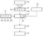
도 1은 본 발명에 따른 자기 공명 장치(11)를 개략적으로 도시한다. 자기 공명 장치(11)는 자석 유닛(13)에 의해 형성된, 강하고 특히 일정한 주자장(18)을 발생하기 위한 주자석(17)을 구비하는 검출기 유닛을 포함한다. 또한, 자기 공명 장치(11)는 피검체(15), 도시된 경우에는 환자(15)를 수용하기 위한 원통형의 환자 수용 영역(14)을 구비하며, 이 경우 환자 수용 영역(14)은 자석 유닛(13)에 의해서 원주 방향으로 원통형으로 둘러싸여 있다. 환자(15)는 자기 공명 장치(11)의 환자 지지 장치(16)에 의해서 환자 수용 영역(14) 안으로 밀려 들어갈 수 있다. 이 목적을 위해, 환자 지지 장치(16)는 환자용 테이블(patient table)을 구비하며, 이 환자용 테이블은 자기 공명 장치(11) 내부에 이동 가능하게 배치되어 있다. 자석 유닛(13)은 자기 공명 장치의 하우징 커버(31)에 의해서 외부에 대해 차폐되어 있다.Fig. 1 schematically shows a
자석 유닛(13)은 또한 자기장 경사를 발생하기 위한 경사 코일 유닛(19)을 구비하며, 이 경사 코일 유닛은 영상화(imaging) 중에 위치 부호화(position encoding)를 위해서 사용된다. 경사 코일 유닛(19)은 경사 제어 유닛(28)에 의해서 제어된다. 또한, 자석 유닛(13)은 고주파 안테나 유닛(20), 및 주자석(17)에 의해 형성되는 주자장(18) 내에서 발생하는 분극을 여기하기 위한 고주파 안테나 제어 유닛(29)을 구비하며, 이때 고주파 안테나 유닛은 도시된 경우에 자기 공명 장치(10) 내부에 견고히 집적된 바디 코일(body coil)로서 형성되어 있다. 고주파 안테나 유닛(20)은 고주파 안테나 제어 유닛(29)에 의해서 제어되고, 실질적으로 환자 수용 영역(14)에 의해 형성되는 검사 공간 내부로 고주파 자기 공명 시퀀스를 방출한다. 고주파 안테나 유닛(20)은 또한 특히 환자(15)로부터 자기 공명 신호를 수신하도록 형성되어 있다.The
주자석(17), 경사 제어 유닛(28) 및 고주파 안테나 제어 유닛(29)을 제어하기 위하여, 자기 공명 장치(11)는 산술 유닛(24)을 구비한다. 산술 유닛(24)은 중앙에서 자기 공명 장치(11)를 제어하는데, 예를 들어 사전에 결정된 영상화 경사 에코 시퀀스(imaging gradient echo sequence)의 실행을 제어한다. 예컨대 영상화 파라미터와 같은 제어 정보 및 재구성된 자기 공명 화상은 자기 공명 장치(11)의 디스플레이 유닛(25) 상에, 예를 들어 하나 이상의 모니터상에 사용자를 위해 디스플레이될 수 있다. 또한, 자기 공명 장치(11)는 입력 유닛(26)을 포함하고, 이 입력 유닛을 이용해서는 스캐닝 과정 동안 사용자에 의해 정보 및/또는 파라미터가 입력될 수 있다. 산술 유닛(24)은 경사 제어 유닛(28) 및/또는 고주파 안테나 제어 유닛(29) 및/또는 디스플레이 유닛(25) 및/또는 입력 유닛(26)을 포함할 수 있다.In order to control the main magnet 17, the
자기 공명 장치(11)는 또한 화상 데이터 수집 유닛(34)을 포함한다. 화상 데이터 수집 유닛(34)은 본 경우에 고주파 안테나 제어 유닛(29) 및 경사 제어 유닛(28)과 함께 자석 유닛(13)에 의해서 형성되어 있다. 자기 공명 장치(11)는 또한 심 유닛(32)(shim unit), 및 심 유닛(32)을 제어하기 위한 심 제어 유닛(33)을 포함한다. 이때, 심 제어 유닛(33)은 데이터 교환의 목적으로 산술 유닛(24)에 연결되어 있다. 심 제어 유닛(33)은 또한 산술 유닛(24)의 일 부분일 수도 있다. 심 유닛(32)은 예컨대 심 코일(shim coil)을 포함한다. 심 코일은, 자석 유닛(13) 내에 배치되어 있는 글로벌 심 코일(global shim coil)에 의해서 형성될 수 있고 그리고/또는 환자 수용 영역(14) 내에 배치되어 있는 로컬 심 코일(local shim coil)에 의해서 형성될 수 있다. 심 유닛(32)의 심 코일을 통해서 흐르는 전류는 심 제어 유닛(33)에 의해 심 설정을 참조해서 조정될 수 있다. 이로써, 자기 공명 장치(11)는 산술 유닛(24), 심 유닛(32), 화상 데이터 수집 유닛(34) 및 심 제어 유닛(33)과 함께 본 발명에 따른 방법을 실시하도록 설계되어 있다.The
도면에 도시된 자기 공명 장치(11)는 당연히 자기 공명 장치(11)가 통상적으로 구비하는 또 다른 부품들을 포함할 수 있다. 또한, 자기 공명 장치(11)의 일반적인 기능 방식도 당업자에게 공지되어 있기 때문에, 또 다른 부품들에 대한 상세한 설명은 생략될 것이다.The
도 2는, 자기 공명 장치(11)를 이용해서 피검체(15)의 자기 공명 영상화를 위한 본 발명에 따른 방법의 제1 실시예의 흐름도를 보여준다.2 shows a flow chart of a first embodiment of a method according to the present invention for magnetic resonance imaging of a subject 15 using a
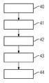
제1 방법 단계(40)에서는, 피검체(15)의 제1 자기 공명 화상 데이터가 자기 공명 장치(11)의 화상 데이터 수집 유닛(34)에 의해서 수집된다. 이와 같은 과정은 예를 들어 피검체(15)의 검사를 시작할 때, 3차원의 스카우트 뷰 데이터 기록(scout view data recording) 동안에 이루어질 수 있다. 또 하나의 방법 단계(41)에서는, 제1 자기 공명 화상 데이터가, 도면에 도시되어 있지 않은 산술 유닛(24)의 분할 유닛에 의해서 두 가지 이상의 재료 부류로 분할된다. 또 하나의 방법 단계(42)에서는, 도면에 도시되어 있지 않은 산술 유닛(24)의 계산 유닛이 분할된 제1 자기 공명 화상 데이터를 참조해서 그리고 두 가지 이상의 재료 부류의 감수성 값을 참조해서 B0 맵을 계산한다. 또 하나의 방법 단계(43)에서는, 계산된 B0 맵을 참조해서 심 제어 유닛(33)에 의해 심 설정이 계산된다. 또 하나의 방법 단계(44)에서는, 이미지 데이터 수집 유닛(34)을 이용해서 피검체의 제2 자기 공명 화상 데이터의 수집이 이루어지며, 이 경우 제2 자기 공명 화상 데이터를 수집하는 동안에는 심 유닛(32)이 계산된 심 설정을 사용해서 심 제어 유닛(33)에 의해 제어된다. 그 다음에 이어서, 제2 자기 공명 화상 데이터는 자기 공명 장치(11)의 디스플레이 유닛(25) 상에 디스플레이될 수 있고 그리고/또는 데이터 베이스에 저장될 수 있다.In the
도 3은 본 발명에 따른 방법의 제2 실시예의 흐름도를 보여준다.Figure 3 shows a flow chart of a second embodiment of the method according to the invention.
이하의 설명은 실질적으로 도 2에 도시된 실시예와의 차이점에 한정되어 있으며, 이 경우 동일한 방법 단계들과 관련해서는 도 2에 도시된 실시예에 대한 설명이 참조될 수 있다. 실질적으로 동일한 방법 단계들에서는 원칙적으로 동일한 도면 부호로 표기되어 있다.The following description is substantially limited to differences with the embodiment shown in Fig. 2, in which case the description of the embodiment shown in Fig. 2 can be referred to in connection with the same method steps. Substantially the same method steps are labeled in principle with the same reference numerals.
도 3에 도시된 본 발명에 따른 방법의 제2 실시예는 실질적으로 도 2에 도시된 본 발명에 따른 방법의 제1 실시예의 방법 단계(40, 41, 42, 43, 44)를 포함한다. 추가로, 도 3에 도시된 본 발명에 따른 방법의 제2 실시예는 추가의 방법 단계들 및 하위 단계들을 포함한다. 도 2에 도시된 추가 방법 단계들 및/또는 하위 단계들 중에 단 일 부분만을 포함하는, 도 3에 대한 대안적인 방법 시퀀스도 생각할 수 있다. 당연히, 도 3에 대한 대안적인 방법 시퀀스도 추가의 방법 단계들 및/또는 하위 단계들을 포함할 수 있다.A second embodiment of the method according to the invention shown in Fig. 3 comprises the method steps 40, 41, 42, 43, 44 of the first embodiment of the method according to the invention substantially as shown in Fig. In addition, the second embodiment of the method according to the invention shown in Fig. 3 comprises additional method steps and sub-steps. Alternative method sequences for FIG. 3, including only a single portion of the additional method steps and / or sub-steps shown in FIG. 2, are contemplated. Of course, alternative method sequences for FIG. 3 may also include additional method steps and / or sub-steps.
제1 방법 단계(40)에서의 제1 자기 공명 화상 데이터의 수집은, 제1 방법 단계(40)의 하위 단계(40a)에서 자기 공명 장치(11)의 환자 지지 장치(16)의 환자용 테이블을 특히 연속으로 이동시키는 동안에 이루어진다. 이로써, 피검체의 큰 용적이 특히 신속하게 수집될 수 있다. 그 결과로서, 제1 방법 단계(40)에서의 제1 자기 공명 화상 데이터의 수집은 제1 기록 영역으로부터 이루어지고, 또 다른 방법 단계(44)에서의 제2 자기 공명 화상 데이터의 수집은 제2 기록 영역으로부터 이루어지며, 이 경우 제2 기록 영역은 제1 기록 영역의 일 부분 영역이다.The collection of the first magnetic resonance image data in the
또 다른 방법 단계(41)에서는, 산술 유닛(24)의 분할 유닛이 제1 자기 공명 화상 데이터를 두 가지 재료 부류(41a, 41b)로 분할하며, 그 중에서 제1 재료 부류(41a)는 공기이고, 제2 재료 부류(41b)는 조직이다. 또 다른 방법 단계(42)에서의 B0 맵의 계산을 위해, 또 다른 방법 단계(47)에서는 재료 부류(41a, 41b)의 개별 감수성 값(47a, 47b)이 데이터 베이스로부터 소환된다. 그 다음에, 또 다른 방법 단계(42)에서의 B0 맵의 계산은, 개별 감수성 값(47a, 47b)이 할당된, 분할된 제1 자기 공명 화상 데이터를 참조해서 이루어진다.In yet another
또 다른 방법 단계(45)에서는, 제2 자기 공명 화상 데이터를 수집하기 전에, 제1 스캔 데이터가, 도면에 도시되어 있지 않고 자기 공명 장치와 상이한, 하나 이상의 또 다른 센서에 의해서 수집된다. 제1 스캔 데이터를 참조하여, 또 다른 방법 단계(46)에서는, 피검체(15)의 윤곽을 기술하는 모델이 산술 유닛(24)에 의해서 결정된다. 이 모델은 또 다른 방법 단계(41)에서 제1 자기 공명 화상 데이터를 분할할 때에 부가된다. 예컨대, 이 모델을 참조해서는, 제1 자기 공명 화상 데이터 외부에 놓여 있는 환자 윤곽들이 결정될 수 있다. 따라서, B0 맵의 계산은 또 다른 방법 단계(42)에서 제1 스캔 데이터를 사용해서 이루어지는데, 말하자면 제1 스캔 데이터로부터 발생 된 모델을 사용해서 이루어진다.In another
또한, 도면에 도시된 경우에는 계산된 B0 맵의 이동 보정이 수행된다. 이 목적을 위하여, 또 다른 방법 단계(48)에서는, 제2 자기 공명 화상 데이터를 수집한 후에 또 다른 센서를 이용해서 제2 스캔 데이터가 수집된다. 제2 스캔 데이터를 참조해서는, 또 다른 방법 단계(46)에서 계산된 모델이 산술 유닛에 의해 또 다른 방법 단계(49)에서 매칭된다. 예를 들면, 피검체의 윤곽이 제2 스캔 데이터에 상응하게 매칭된다. 또 다른 방법 단계(42)에서 계산된 B0 맵으로부터, 매칭되는 모델을 부가하여, 매칭되는 B0 맵이 또 다른 방법 단계(50)에서 결정된다. 그 다음에, 심 제어 유닛(33)은 또 다른 방법 단계(51)에서, 매칭되는 B0 맵을 참조하여 매칭되는 심 설정을 계산할 수 있다. 그 다음에, 화상 데이터 수집 유닛(34)을 이용해서 제3 자기 공명 화상 데이터(52)를 수집하기 위해, 심 유닛(32)은 매칭되는 심 설정을 사용해서 심 제어 유닛(33)에 의해 제어된다.Also, in the case shown in the drawing, the calculated movement correction of the B0 map is performed. For this purpose, in another
도 4는 본 발명에 따른 방법의 제3 실시예의 흐름도를 보여준다.Figure 4 shows a flow diagram of a third embodiment of the method according to the invention.
이하의 설명은 실질적으로 도 2에 도시된 실시예와의 차이점에 한정되어 있으며, 이 경우 동일한 방법 단계들과 관련해서는 도 2에 도시된 실시예에 대한 설명이 참조될 수 있다. 실질적으로 동일한 방법 단계들에서는 원칙적으로 동일한 도면 부호로 표기되어 있다.The following description is substantially limited to differences with the embodiment shown in Fig. 2, in which case the description of the embodiment shown in Fig. 2 can be referred to in connection with the same method steps. Substantially the same method steps are labeled in principle with the same reference numerals.
도 4에 도시된 본 발명에 따른 방법의 제3 실시예는 실질적으로 도 2에 도시된 본 발명에 따른 방법의 제1 실시예의 방법 단계(40, 41, 42, 43, 44)를 포함한다. 또한, 도 4에 도시된 방법 시퀀스는 도 3에 도시된 방법의 제2 실시예의 또 다른 방법 단계(47)를 포함한다. 추가로, 도 4에 도시된 본 발명에 따른 방법의 제3 실시예는 추가의 방법 단계들 및 하위 단계들을 포함한다. 도 2에 도시된 추가 방법 단계들 및/또는 하위 단계들 중에 단 일 부분만을 포함하는, 도 4에 대한 대안적인 방법 시퀀스도 생각할 수 있다. 당연히, 도 4에 대한 대안적인 방법 시퀀스도 추가의 방법 단계들 및/또는 하위 단계들을 포함할 수 있다.A third embodiment of the method according to the invention shown in Fig. 4 comprises the method steps 40, 41, 42, 43, 44 of the first embodiment of the method according to the invention substantially as shown in Fig. In addition, the method sequence shown in Fig. 4 includes another
또 다른 방법 단계(41)에서는, 산술 유닛(24)의 분할 유닛이 제1 자기 공명 화상 데이터를 네 가지의 재료 부류(41a, 41b, 41c, 41d)로 분할하며, 그 중에서 제1 재료 부류(41a)는 공기이고, 제2 재료 부류(41b)는 지방 조직이며, 제3 재료 부류(41c)는 물 조직이고, 제4 재료 부류(41d)는 뼈 조직이다. 이로써, 네 가지의 재료 부류(41a, 41b, 41c, 41d)는 세 가지의 상이한 조직 부류(41b, 41c, 41d)를 포함하게 된다. 또 다른 방법 단계(42)에서 B0 맵을 계산하기 위해, 또 다른 방법 단계(47)에서는 재료 부류(41a, 41b, 41c, 41d)의 개별 감수성 값(47a, 47b, 47c, 47d)이 데이터 베이스로부터 소환된다. 그 다음에, 또 다른 방법 단계(42)에서의 B0 맵의 계산은, 개별 감수성 값(47a, 47b, 47c, 47d)이 할당된, 분할된 제1 자기 공명 화상 데이터를 참조해서 이루어진다. 당연히, 도 3 및 도 4에 도시된 분할 방식과 상이한 방식으로 제1 자기 공명 화상 데이터를 재료 부류로 분할하는 것도 생각할 수 있다.In another
도 4에 도시된 실시예에서는, 피검체(15)와 무관한 자기 공명 장치(11)의 주자장(18)의 비균질성이 심 설정을 계산할 때에 고려된다. 이와 같은 과정은 도 3에 도시된 B0 맵의 이동 교정에 추가로 이루어질 수도 있다.In the embodiment shown in Fig. 4, the heterogeneity of the
먼저, 또 다른 방법 단계(53)에서는, 자기 공명 장치(11)의 화상 데이터 수집 유닛(34)을 이용해서 제2 자기 공명 화상 데이터를 수집하기 전에 보정 스캔이 수행된다. 보정 스캔 동안에 보정 자기 공명 화상 데이터가 수집된다. 이 보정 자기 공명 화상 데이터를 참조해서, 피검체(15)와 무관한 자기 공명 장치(11)의 주자장(18)의 비균질성이 결정된다. 이 비균질성은, 대안적으로 또는 추가로는, 주자석(17)의 형성에 대한 공지된 정보를 참조해서도 설정될 수 있다. 또한, 시뮬레이션에 의해서 비균질성을 결정하는 것도 생각할 수 있다.First, in another
피검체(15)와 무관한 주자장의 비균질성은, 또 다른 방법 단계(42)에서 B0 맵을 계산할 시에, 또 다른 방법 단계(54)에서 산술 유닛(24)의 계산 유닛에 의해 고려된다.The inhomogeneity of the
도 2, 도 3 및 도 4에 도시된 본 발명에 따른 방법의 방법 단계들은 자기 공명 장치에 의해서 실시된다. 이 목적을 위해 자기 공명 장치는, 산술 유닛의 및/또는 자기 공명 장치의 제어 유닛의 저장 유닛에 저장되어 있는 필요한 소프트웨어 및/또는 컴퓨터 프로그램을 포함한다. 소프트웨어 및/또는 컴퓨터 프로그램은, 산술 유닛 및/또는 제어 유닛 내에 있는 컴퓨터 프로그램 및/또는 소프트웨어가 산술 유닛의 및/또는 제어 유닛의 프로세서 유닛에 의해 실행될 때에, 본 발명에 따른 방법을 실시하도록 설계되어 있는 프로그램 수단을 포함한다.The method steps of the method according to the invention shown in Figures 2, 3 and 4 are carried out by means of a magnetic resonance apparatus. For this purpose, the magnetic resonance apparatus includes necessary software and / or computer programs stored in a storage unit of the control unit of the arithmetic unit and / or the magnetic resonance apparatus. The software and / or computer program is designed to carry out the method according to the invention when the computer program and / or software in the arithmetic unit and / or control unit is executed by the processor unit of the arithmetic unit and / or the control unit Lt; / RTI >
본 발명의 세부 내용이 바람직한 실시예에 의해 더 상세하게 도시되고 기술되었지만, 본 발명은 개시된 예들에 의해서 한정되지 않으며, 본 발명의 보호 범위를 벗어나지 않는 다른 변형 예들도 당업자에 의해서 도출될 수 있다.While the present invention has been particularly shown and described with reference to preferred embodiments thereof, it is to be understood that the invention is not limited to the disclosed examples, and other modifications may be made by those skilled in the art without departing from the scope of protection of the invention.
Claims (11)
- 자기 공명 장치를 이용해서 피검체의 제1 자기 공명 화상 데이터를 수집하는 단계,
- 제1 자기 공명 화상 데이터를 두 가지 이상의 재료 부류로 분할하는 단계,
- 분할된 제1 자기 공명 화상 데이터를 참조해서 그리고 두 가지 이상의 재료 부류의 감수성 값(susceptibility value)을 참조해서 B0 맵을 계산하는 단계,
- 계산된 B0 맵을 참조해서 심 설정을 계산하는 단계,
- 자기 공명 장치를 이용해서 피검체의 제2 자기 공명 화상 데이터를 수집하는 단계이며, 이때 제2 자기 공명 화상 데이터의 수집은 계산된 심 설정을 사용해서 이루어지는 단계를 포함하는, 자기 공명 영상화 방법.A magnetic resonance imaging method of a subject using a magnetic resonance apparatus,
- collecting first magnetic resonance image data of the subject using a magnetic resonance apparatus,
Dividing the first magnetic resonance image data into two or more material classes,
Calculating a B0 map with reference to the divided first magnetic resonance image data and with reference to susceptibility values of two or more material classes,
Calculating a shim setting by referring to the calculated B0 map,
- collecting second magnetic resonance image data of the subject using a magnetic resonance apparatus, wherein the acquisition of the second magnetic resonance image data comprises using a calculated shimming setting.
- 제2 스캔 데이터가 또 다른 센서에 의해서 수집되고,
- 매칭되는 B0 맵이 상기 제2 스캔 데이터 및 계산된 B0 맵을 참조해서 결정되며,
- 매칭되는 심 설정이 상기 매칭되는 B0 맵을 참조해서 계산되고,
- 제3 자기 공명 화상 데이터가 자기 공명 장치를 이용해서 피검체로부터 수집되며, 제3 자기 공명 화상 데이터의 수집은 매칭되는 심 설정을 사용해서 이루어지는, 자기 공명 영상화 방법.7. The method according to claim 6, wherein after collecting the second magnetic resonance image data,
- the second scan data is collected by another sensor,
A matching B0 map is determined with reference to the second scan data and the calculated B0 map,
- the matching shim settings are calculated with reference to the matched B0 map,
The third magnetic resonance imaging data is collected from the subject using a magnetic resonance apparatus and the collection of third magnetic resonance imaging data is made using a matching shimming setting.
제1항 또는 제2항에 따른 방법을 실시하도록 형성되는, 자기 공명 장치.1. A magnetic resonance apparatus comprising an image data acquisition unit, a heart unit, an arithmetic unit and a heart control unit,
A magnetic resonance apparatus formed to carry out the method according to claim 1 or 2.
Applications Claiming Priority (2)
| Application Number | Priority Date | Filing Date | Title |
|---|---|---|---|
| DE102014211354.7A DE102014211354A1 (en) | 2014-06-13 | 2014-06-13 | Method for magnetic resonance imaging |
| DE102014211354.7 | 2014-06-13 |
Publications (1)
| Publication Number | Publication Date |
|---|---|
| KR20150143329A true KR20150143329A (en) | 2015-12-23 |
Family
ID=54706635
Family Applications (1)
| Application Number | Title | Priority Date | Filing Date |
|---|---|---|---|
| KR1020150081703A KR20150143329A (en) | 2014-06-13 | 2015-06-10 | Method for magnetic resonance imaging |
Country Status (5)
| Country | Link |
|---|---|
| US (1) | US20150362578A1 (en) |
| JP (1) | JP2016002464A (en) |
| KR (1) | KR20150143329A (en) |
| CN (1) | CN105167773A (en) |
| DE (1) | DE102014211354A1 (en) |
Families Citing this family (9)
| Publication number | Priority date | Publication date | Assignee | Title |
|---|---|---|---|---|
| DE102013216529B4 (en) * | 2013-08-21 | 2019-05-23 | Siemens Healthcare Gmbh | Method in particular for the patient-adaptive B0 homogenization of MR systems using different types of shim coils |
| EP3351956B1 (en) | 2017-01-19 | 2022-03-16 | Siemens Healthcare GmbH | Method for classification of magnetic resonance measuring data recorded by means of a magnetic resonance fingerprinting method of an object to be examined |
| DE102017215002A1 (en) * | 2017-08-28 | 2019-02-28 | Siemens Healthcare Gmbh | Method for recording a B0 card with a magnetic resonance device, magnetic resonance device, computer program and electronically readable data carrier |
| DE102017221830A1 (en) * | 2017-12-04 | 2019-06-06 | Siemens Healthcare Gmbh | Characterization of a disruptive body within an examination object based on a medical image data set |
| EP3591418A1 (en) | 2018-07-03 | 2020-01-08 | Koninklijke Philips N.V. | Mri method for b0-mapping |
| JP7140606B2 (en) * | 2018-08-29 | 2022-09-21 | 富士フイルムヘルスケア株式会社 | Image processing device, image processing method, image processing program, and magnetic resonance imaging device |
| CN110074786B (en) * | 2019-04-30 | 2022-12-06 | 上海东软医疗科技有限公司 | Nuclear magnetic resonance shimming method and device, computing equipment and nuclear magnetic resonance imaging system |
| DE102021210969A1 (en) * | 2021-09-30 | 2023-03-30 | Siemens Healthcare Gmbh | Control of a magnetic resonance device with saturation |
| EP4273569A1 (en) * | 2022-05-04 | 2023-11-08 | Siemens Healthcare GmbH | Method for generating a subject-specific map of a tissue property |
Family Cites Families (12)
| Publication number | Priority date | Publication date | Assignee | Title |
|---|---|---|---|---|
| US6064208A (en) * | 1998-04-02 | 2000-05-16 | Picker International, Inc. | Two-peak alignment method of field shimming |
| US7944209B2 (en) * | 2006-03-31 | 2011-05-17 | Hitachi Medical Corporation | Magnetic resonance imaging apparatus and method |
| JP5214209B2 (en) * | 2007-10-17 | 2013-06-19 | 株式会社日立メディコ | Magnetic resonance imaging system |
| WO2011127942A1 (en) * | 2010-04-14 | 2011-10-20 | Universitätsklinikum Freiburg | Method for correcting susceptibility-induced image artifacts in mri after prospective motion correction |
| EP2461175A1 (en) * | 2010-12-02 | 2012-06-06 | Koninklijke Philips Electronics N.V. | MR imaging using a multi-point Dixon technique |
| CN103238082B (en) * | 2010-12-02 | 2015-07-15 | 皇家飞利浦电子股份有限公司 | MR imaging using a multi-point Dixon technique and low resolution calibration |
| JP5917077B2 (en) * | 2011-10-13 | 2016-05-11 | 株式会社東芝 | Magnetic resonance imaging system |
| EP2610632A1 (en) * | 2011-12-29 | 2013-07-03 | Koninklijke Philips Electronics N.V. | MRI with Dixon-type water/fat separation and prior knowledge about inhomogeneity of the main magnetic field |
| EP2626718A1 (en) * | 2012-02-09 | 2013-08-14 | Koninklijke Philips Electronics N.V. | MRI with motion correction using navigators acquired using a Dixon technique |
| DE102015200695B4 (en) * | 2015-01-19 | 2016-08-18 | Siemens Healthcare Gmbh | Generate control information for magnetic resonance imaging using multiple frequency spectra from different coil elements |
| DE102015204955B4 (en) * | 2015-03-19 | 2019-05-16 | Siemens Healthcare Gmbh | Method for magnetic resonance imaging |
| DE102015204953B3 (en) * | 2015-03-19 | 2016-08-11 | Siemens Healthcare Gmbh | Method for magnetic resonance imaging |
-
2014
- 2014-06-13 DE DE102014211354.7A patent/DE102014211354A1/en not_active Ceased
-
2015
- 2015-06-09 JP JP2015116786A patent/JP2016002464A/en active Pending
- 2015-06-10 KR KR1020150081703A patent/KR20150143329A/en not_active Application Discontinuation
- 2015-06-12 CN CN201510477943.8A patent/CN105167773A/en active Pending
- 2015-06-13 US US14/738,884 patent/US20150362578A1/en not_active Abandoned
Also Published As
| Publication number | Publication date |
|---|---|
| DE102014211354A1 (en) | 2015-12-17 |
| CN105167773A (en) | 2015-12-23 |
| US20150362578A1 (en) | 2015-12-17 |
| JP2016002464A (en) | 2016-01-12 |
Similar Documents
| Publication | Publication Date | Title |
|---|---|---|
| KR20150143329A (en) | Method for magnetic resonance imaging | |
| JP5736459B2 (en) | Medical imaging device | |
| US9712789B2 (en) | Method and apparatus to generate image data | |
| US9626777B2 (en) | Method and apparatus to generate image data | |
| US20100189328A1 (en) | Method of automatically acquiring magnetic resonance image data | |
| JP5575491B2 (en) | Medical diagnostic imaging equipment | |
| JP2015506775A (en) | MRI with motion compensation using navigator acquired using Dixon method | |
| JP2011194241A (en) | System and method for automatic computation of mr imaging scan parameter | |
| JP5943159B2 (en) | Magnetic resonance imaging system | |
| JP2006314491A (en) | Magnetic resonance imaging system | |
| US11544842B2 (en) | Medical image diagnostic apparatus, medical imaging apparatus and medical imaging method | |
| JP5603642B2 (en) | Magnetic resonance imaging apparatus and shimming method | |
| KR101625713B1 (en) | Method and apparatus to generate magnetic resonance images | |
| US11525877B2 (en) | Magnetic resonance imaging apparatus, subject positioning device, and subject positioning method | |
| US10345406B2 (en) | Method and apparatus for magnetic resonance imaging | |
| US11249154B2 (en) | Magnetic resonance imaging apparatus | |
| JP2021083730A (en) | Magnetic resonance imaging device | |
| JP6280591B2 (en) | Magnetic resonance imaging system | |
| JP4763429B2 (en) | Magnetic resonance imaging system | |
| JP6408954B2 (en) | Magnetic resonance imaging apparatus, information processing apparatus, and high-frequency magnetic field shimming method | |
| JP7357516B2 (en) | Magnetic resonance imaging device and its control method | |
| JP7076224B2 (en) | Magnetic resonance imaging device | |
| JP6715165B2 (en) | Magnetic resonance imaging apparatus and image processing method | |
| JP2016214277A5 (en) |
Legal Events
| Date | Code | Title | Description |
|---|---|---|---|
| A201 | Request for examination | ||
| E902 | Notification of reason for refusal | ||
| E601 | Decision to refuse application | ||
| AMND | Amendment | ||
| E902 | Notification of reason for refusal |