KR20150135546A - Image predictive encoding device, image predictive encoding method, image predictive decoding device, and image predictive decoding method - Google Patents
Image predictive encoding device, image predictive encoding method, image predictive decoding device, and image predictive decoding method Download PDFInfo
- Publication number
- KR20150135546A KR20150135546A KR1020157032965A KR20157032965A KR20150135546A KR 20150135546 A KR20150135546 A KR 20150135546A KR 1020157032965 A KR1020157032965 A KR 1020157032965A KR 20157032965 A KR20157032965 A KR 20157032965A KR 20150135546 A KR20150135546 A KR 20150135546A
- Authority
- KR
- South Korea
- Prior art keywords
- signal
- prediction
- area
- adjacent
- target
- Prior art date
Links
Images


Classifications
-
- H—ELECTRICITY
- H04—ELECTRIC COMMUNICATION TECHNIQUE
- H04N—PICTORIAL COMMUNICATION, e.g. TELEVISION
- H04N19/00—Methods or arrangements for coding, decoding, compressing or decompressing digital video signals
- H04N19/50—Methods or arrangements for coding, decoding, compressing or decompressing digital video signals using predictive coding
-
- H—ELECTRICITY
- H04—ELECTRIC COMMUNICATION TECHNIQUE
- H04N—PICTORIAL COMMUNICATION, e.g. TELEVISION
- H04N19/00—Methods or arrangements for coding, decoding, compressing or decompressing digital video signals
- H04N19/10—Methods or arrangements for coding, decoding, compressing or decompressing digital video signals using adaptive coding
- H04N19/102—Methods or arrangements for coding, decoding, compressing or decompressing digital video signals using adaptive coding characterised by the element, parameter or selection affected or controlled by the adaptive coding
- H04N19/103—Selection of coding mode or of prediction mode
- H04N19/105—Selection of the reference unit for prediction within a chosen coding or prediction mode, e.g. adaptive choice of position and number of pixels used for prediction
-
- H—ELECTRICITY
- H04—ELECTRIC COMMUNICATION TECHNIQUE
- H04N—PICTORIAL COMMUNICATION, e.g. TELEVISION
- H04N19/00—Methods or arrangements for coding, decoding, compressing or decompressing digital video signals
- H04N19/10—Methods or arrangements for coding, decoding, compressing or decompressing digital video signals using adaptive coding
- H04N19/102—Methods or arrangements for coding, decoding, compressing or decompressing digital video signals using adaptive coding characterised by the element, parameter or selection affected or controlled by the adaptive coding
- H04N19/119—Adaptive subdivision aspects, e.g. subdivision of a picture into rectangular or non-rectangular coding blocks
-
- H—ELECTRICITY
- H04—ELECTRIC COMMUNICATION TECHNIQUE
- H04N—PICTORIAL COMMUNICATION, e.g. TELEVISION
- H04N19/00—Methods or arrangements for coding, decoding, compressing or decompressing digital video signals
- H04N19/10—Methods or arrangements for coding, decoding, compressing or decompressing digital video signals using adaptive coding
- H04N19/134—Methods or arrangements for coding, decoding, compressing or decompressing digital video signals using adaptive coding characterised by the element, parameter or criterion affecting or controlling the adaptive coding
- H04N19/136—Incoming video signal characteristics or properties
-
- H—ELECTRICITY
- H04—ELECTRIC COMMUNICATION TECHNIQUE
- H04N—PICTORIAL COMMUNICATION, e.g. TELEVISION
- H04N19/00—Methods or arrangements for coding, decoding, compressing or decompressing digital video signals
- H04N19/10—Methods or arrangements for coding, decoding, compressing or decompressing digital video signals using adaptive coding
- H04N19/169—Methods or arrangements for coding, decoding, compressing or decompressing digital video signals using adaptive coding characterised by the coding unit, i.e. the structural portion or semantic portion of the video signal being the object or the subject of the adaptive coding
- H04N19/17—Methods or arrangements for coding, decoding, compressing or decompressing digital video signals using adaptive coding characterised by the coding unit, i.e. the structural portion or semantic portion of the video signal being the object or the subject of the adaptive coding the unit being an image region, e.g. an object
- H04N19/176—Methods or arrangements for coding, decoding, compressing or decompressing digital video signals using adaptive coding characterised by the coding unit, i.e. the structural portion or semantic portion of the video signal being the object or the subject of the adaptive coding the unit being an image region, e.g. an object the region being a block, e.g. a macroblock
-
- H—ELECTRICITY
- H04—ELECTRIC COMMUNICATION TECHNIQUE
- H04N—PICTORIAL COMMUNICATION, e.g. TELEVISION
- H04N19/00—Methods or arrangements for coding, decoding, compressing or decompressing digital video signals
- H04N19/44—Decoders specially adapted therefor, e.g. video decoders which are asymmetric with respect to the encoder
-
- H—ELECTRICITY
- H04—ELECTRIC COMMUNICATION TECHNIQUE
- H04N—PICTORIAL COMMUNICATION, e.g. TELEVISION
- H04N19/00—Methods or arrangements for coding, decoding, compressing or decompressing digital video signals
- H04N19/50—Methods or arrangements for coding, decoding, compressing or decompressing digital video signals using predictive coding
- H04N19/503—Methods or arrangements for coding, decoding, compressing or decompressing digital video signals using predictive coding involving temporal prediction
- H04N19/51—Motion estimation or motion compensation
- H04N19/537—Motion estimation other than block-based
- H04N19/543—Motion estimation other than block-based using regions
-
- H—ELECTRICITY
- H04—ELECTRIC COMMUNICATION TECHNIQUE
- H04N—PICTORIAL COMMUNICATION, e.g. TELEVISION
- H04N19/00—Methods or arrangements for coding, decoding, compressing or decompressing digital video signals
- H04N19/50—Methods or arrangements for coding, decoding, compressing or decompressing digital video signals using predictive coding
- H04N19/593—Methods or arrangements for coding, decoding, compressing or decompressing digital video signals using predictive coding involving spatial prediction techniques
-
- H—ELECTRICITY
- H04—ELECTRIC COMMUNICATION TECHNIQUE
- H04N—PICTORIAL COMMUNICATION, e.g. TELEVISION
- H04N19/00—Methods or arrangements for coding, decoding, compressing or decompressing digital video signals
- H04N19/60—Methods or arrangements for coding, decoding, compressing or decompressing digital video signals using transform coding
- H04N19/61—Methods or arrangements for coding, decoding, compressing or decompressing digital video signals using transform coding in combination with predictive coding
-
- H—ELECTRICITY
- H04—ELECTRIC COMMUNICATION TECHNIQUE
- H04N—PICTORIAL COMMUNICATION, e.g. TELEVISION
- H04N19/00—Methods or arrangements for coding, decoding, compressing or decompressing digital video signals
- H04N19/10—Methods or arrangements for coding, decoding, compressing or decompressing digital video signals using adaptive coding
- H04N19/102—Methods or arrangements for coding, decoding, compressing or decompressing digital video signals using adaptive coding characterised by the element, parameter or selection affected or controlled by the adaptive coding
- H04N19/103—Selection of coding mode or of prediction mode
- H04N19/109—Selection of coding mode or of prediction mode among a plurality of temporal predictive coding modes
-
- H—ELECTRICITY
- H04—ELECTRIC COMMUNICATION TECHNIQUE
- H04N—PICTORIAL COMMUNICATION, e.g. TELEVISION
- H04N19/00—Methods or arrangements for coding, decoding, compressing or decompressing digital video signals
- H04N19/10—Methods or arrangements for coding, decoding, compressing or decompressing digital video signals using adaptive coding
- H04N19/102—Methods or arrangements for coding, decoding, compressing or decompressing digital video signals using adaptive coding characterised by the element, parameter or selection affected or controlled by the adaptive coding
- H04N19/103—Selection of coding mode or of prediction mode
- H04N19/11—Selection of coding mode or of prediction mode among a plurality of spatial predictive coding modes
-
- H—ELECTRICITY
- H04—ELECTRIC COMMUNICATION TECHNIQUE
- H04N—PICTORIAL COMMUNICATION, e.g. TELEVISION
- H04N19/00—Methods or arrangements for coding, decoding, compressing or decompressing digital video signals
- H04N19/10—Methods or arrangements for coding, decoding, compressing or decompressing digital video signals using adaptive coding
- H04N19/189—Methods or arrangements for coding, decoding, compressing or decompressing digital video signals using adaptive coding characterised by the adaptation method, adaptation tool or adaptation type used for the adaptive coding
- H04N19/196—Methods or arrangements for coding, decoding, compressing or decompressing digital video signals using adaptive coding characterised by the adaptation method, adaptation tool or adaptation type used for the adaptive coding being specially adapted for the computation of encoding parameters, e.g. by averaging previously computed encoding parameters
-
- H—ELECTRICITY
- H04—ELECTRIC COMMUNICATION TECHNIQUE
- H04N—PICTORIAL COMMUNICATION, e.g. TELEVISION
- H04N19/00—Methods or arrangements for coding, decoding, compressing or decompressing digital video signals
- H04N19/46—Embedding additional information in the video signal during the compression process
Abstract
예측 정보의 증가를 억제하면서, 대상 블록의 예측 오차를 저감하고, 화상을 효율적으로 부호화할 수 있는 화상 예측 부호화 장치를 제공한다. 일실시예의 화상 예측 부호화 장치에서는, 대상 영역 내의 부분 영역의 예측 신호의 생성에, 인접 영역의 예측 정보가 이용 가능한지의 여부가 판정된다. 이용 가능한 경우에는, 인접 영역의 예측 정보를 사용하여 예측 신호를 생성하는 부분 영역의 영역 폭이 결정된다. 대상 영역의 예측 신호는, 대상 영역의 예측 정보, 인접 영역의 예측 정보, 및 영역 폭에 기초하여, 기(旣) 재생 신호로부터 생성된다. 예측 정보, 영역 폭을 특정하기 위한 정보, 예측 신호와 대상 영역의 화상 신호와의 사이의 잔차(殘差) 신호가, 부호화된다.Provided is an image predictive encoding apparatus capable of reducing a prediction error of a target block while suppressing an increase in predictive information and efficiently encoding an image. In the image predictive encoding apparatus of one embodiment, it is determined whether or not prediction information of the adjacent area is available for generation of the prediction signal of the partial area in the target area. If available, the area width of the partial area for generating the prediction signal is determined using the prediction information of the adjacent area. The prediction signal of the target area is generated from the playback signal based on the prediction information of the target area, the prediction information of the adjacent area, and the area width. The prediction information, the information for specifying the area width, and the residual signal between the prediction signal and the image signal of the object area are coded.
Description
본 발명은, 화상 예측 부호화 장치, 화상 예측 부호화 방법, 화상 예측 복호 장치, 및 화상 예측 복호 방법에 관한 것이다. 보다 상세하게는, 본 발명은, 영역 분할을 사용하여 예측 부호화 및 예측 복호를 행하는 화상 예측 부호화 장치, 화상 예측 부호화 방법, 화상 예측 부호화 프로그램, 화상 예측 복호 장치, 화상 예측 복호 방법, 및 화상 예측 복호 프로그램에 관한 것이다.The present invention relates to an image predictive encoding apparatus, an image predictive encoding method, an image predictive decoding apparatus, and an image predictive decoding method. More particularly, the present invention relates to an image predictive encoding apparatus, an image predictive encoding method, an image predictive encoding program, an image predictive decoding apparatus, an image predictive decoding method, and an image predictive decoding method for performing predictive encoding and predictive decoding using area division Program.
정지 화상이나 동영상 데이터의 전송이나 축적을 효율적으로 행하기 위하여, 압축 부호화 기술이 사용되고 있다. 동영상의 압축 부호화 방식으로서는, MPEG-1∼4나 ITU(International Telecommunication Union) H.261∼H.264의 방식이 널리 사용되고 있다.In order to efficiently perform transmission and storage of still image and moving image data, a compression encoding technique is used. MPEG-1 to 4 and ITU (International Telecommunication Union) H.261 to H.264 schemes are widely used as compression encoding methods of moving pictures.
이들 부호화 방식에서는, 부호화의 대상이 되는 화상을 복수의 블록으로 분할한 후에 부호화·복호 처리가 행해진다. 화면 내의 예측 부호화에서는, 대상 블록과 동일 화면 내의 인접하는, 기(旣) 재생의 화상 신호를 사용하여, 대상 블록의 예측 신호가 생성된다. 여기서, 기 재생의 화상 신호는, 압축된 화상 데이터가 복원된 것이다. 이어서, 화면 내의 예측 부호화에서는, 예측 신호를 대상 블록의 신호로부터 감산함으로써 차분 신호가 생성되지만, 상기 차분 신호가 부호화된다. 화면간의 예측 부호화에서는, 대상 블록과는 상이한 화면 내의 기 재생의 화상 신호를 참조하여, 움직임을 보정함으로써, 예측 신호가 생성된다. 이어서, 화면간의 예측 부호화에서는, 예측 신호를 대상 블록의 신호로부터 뺄셈함으로서 차분 신호가 생성되고, 상기 차분 신호가 부호화된다.In these coding schemes, an image to be encoded is divided into a plurality of blocks, and then the coding and decoding processes are performed. In predictive coding in the picture, a prediction signal of a target block is generated by using adjacent (renewed) reproduction image signals in the same screen as the target block. Here, the image signal to be reproduced is the restored compressed image data. Subsequently, in the intra prediction encoding, a difference signal is generated by subtracting the prediction signal from the signal of the object block, but the difference signal is encoded. In predictive encoding between pictures, a prediction signal is generated by correcting the motion with reference to an image signal of a periodical reproduction within a screen different from the target block. Subsequently, in predictive encoding between pictures, a difference signal is generated by subtracting the prediction signal from the signal of the target block, and the difference signal is encoded.
예를 들면, H.264의 화면 내 예측 부호화에서는, 부호화의 대상이 되는 블록에 인접하는 화소의 기 재생의 화소값(재생 신호)을 소정의 방향으로 외삽(外揷)함으로써 예측 신호를 생성하는 방법이 채용되었다. 도 20은, ITUH.264에서 사용되고 있는 화면 내 예측 방법을 설명하기 위한 모식도이다. 도 20의 (a)는, 수직 방향으로 외삽을 행하는 화면 내 예측 방법을 나타내고 있다. 도 20의 (a)에 있어서, 4×4화소의 대상 블록(802)은 부호화의 대상이 되는 대상 블록이다. 이 대상 블록(802)의 경계에 인접하는 화소 A∼M으로 이루어지는 화소군(801)은 인접 영역이며, 과거의 처리에 있어서 이미 재생된 화상 신호이다. 도 20의 (a)에 나타내는 예측에서는, 대상 블록(802)의 바로 위에 있는 인접 화소 A∼D의 화소값이 하측으로 외삽됨으로써, 예측 신호가 생성된다.For example, in intra-frame prediction coding of H.264, a prediction signal is generated by extrapolating (replaying) the pixel value (reproduction signal) of the initial reproduction of the pixel adjacent to the block to be encoded in a predetermined direction Method was adopted. 20 is a schematic diagram for explaining an intra prediction method used in ITUH.264. 20 (a) shows an intra prediction method in which extrapolation is performed in the vertical direction. 20A, the 4x4
또한, 도 20의 (b)는, 수평 방향으로 외삽을 행하는 화면 내 예측 방법을 나타내고 있다. 도 20의 (b)에 나타내는 예측에서는, 대상 블록(802)의 좌측에 있는 기 재생 화소 I∼L의 화소값이 우측 방향으로 외삽됨으로써, 예측 신호가 생성된다.20 (b) shows an intra prediction method in which extrapolation is performed in the horizontal direction. In the prediction shown in FIG. 20 (b), the pixel values of the basic pixels I to L on the left side of the
화면 내 예측 방법에서는, 도 20의 (a)∼(i)에 나타내는 방법으로 생성된 9개의 예측 신호 중, 대상 블록의 화소 신호로부터의 차분이 최소로 되는 예측 신호가, 대상 블록용의 최적의 예측 신호로서 채용된다. 이와 같이 예측 신호를 생성하는 구체적인 방법은, 예를 들면, 특허 문헌 1에 기재되어 있다.In the intra prediction method, among the nine prediction signals generated by the methods shown in Figs. 20A to 20I, a prediction signal in which the difference from the pixel signal of the target block is minimized is the optimum And is employed as a prediction signal. A specific method of generating the prediction signal in this manner is described in, for example,
통상적인 화면간 예측 부호화에서는, 부호화의 대상이 되는 대상 블록의 화소 신호와 유사한 신호를 재생이 종료된 화면으로부터 탐색함으로써, 예측 신호가 생성된다. 이 화면간 예측 부호화에서는, 동작 벡터와, 대상 블록의 화소 신호와 예측 신호와의 사이의 잔차(殘差) 신호가 부호화된다. 그리고, 동작 벡터는, 대상 블록과 탐색된 신호가 존재하는 영역과의 사이의 공간적인 변위량을 규정하는 벡터이다. 이와 같이 블록마다 동작 벡터를 탐색하는 방법은 블록 매칭으로 불린다.In a typical inter picture prediction coding, a prediction signal is generated by searching for a signal similar to a pixel signal of a target block to be coded from a picture on which reproduction has been completed. In this inter picture prediction coding, a motion vector and a residual signal between the pixel signal of the target block and the prediction signal are coded. The motion vector is a vector that defines the amount of spatial displacement between the target block and the region in which the searched signal exists. The method of searching motion vectors for each block is called block matching.
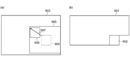
도 21은, 블록 매칭을 설명하기 위한 모식도이다. 도 21에 있어서는, (a)에 기 재생의 화면(903)이 표시되어 있고, (b)에 대상 블록(902)을 포함하는 화면(901)이 나타내어져 있다. 여기서, 화면(903) 내의 영역(904)은, 대상 블록(902)과 공간적으로 동일한 위치에 존재하는 영역이다. 블록 매칭에서는, 영역(904)을 둘러싸는 탐색 범위(905)가 설정되고, 이 탐색 범위의 화소 신호로부터 대상 블록(402)의 화소 신호와의 절대값 오차의 합이 최소로 되는 영역(906)이 검출된다. 이 영역(906)의 신호가 예측 신호가 되어, 영역(904)으로부터 영역(906)으로의 변위량을 규정하는 벡터가 동작 벡터(907)로서 검출된다.21 is a schematic diagram for explaining block matching. 21, a
그리고, 블록 매칭으로서는, 참조 화면(903)을 복수 준비하고, 대상 블록마다 블록 매칭을 실시하는 참조 화면을 선택하고, 참조 화면 선택 정보를 검출하는 방법도 사용될 수 있다. 또한, H.264에서는, 화상의 국소적인 특징의 변화에 대응하기 위해, 동작 벡터를 부호화하는 블록 사이즈가 상이한 복수의 예측 타입을 준비하고 있다. H.264의 예측 타입에 대해서는, 예를 들면, 특허 문헌 2에 기재되어 있다.As the block matching, a method of preparing a plurality of
동영상 데이터의 압축 부호화에서는, 각 화면(프레임, 필드)의 부호화 순서는 임의로 정해질 수 있다. 그러므로, 재생이 종료된 화면을 참조하여 예측 신호를 생성하는 화면간 예측에도, 부호화 순서는 3종류의 방법이 있다. 제1 방법은, 재생 순서에서 과거에 재생이 종료된 화면을 참조하여 예측 신호를 생성하는 전방향(前方向) 예측이며, 제2 방법은, 재생 순서에서 미래의 재생이 종료될 화면을 참조하여 예측 신호를 생성하는 후방향(後方向) 예측이며, 제3 방법은, 전방향 예측과 후방향 예측을 함께 행하여, 2개의 예측 신호를 평균화하는 양방향(兩方向) 예측이다. 화면간 예측의 종류에 대해서는, 예를 들면, 특허 문헌 3에 기재되어 있다.In the compression encoding of moving picture data, the coding order of each screen (frame, field) can be arbitrarily determined. Therefore, there are also three types of encoding procedures in the inter picture prediction for generating a prediction signal with reference to the picture on which reproduction has been completed. The first method is a forward direction prediction in which a prediction signal is generated with reference to a screen in which reproduction has been completed in the past in the reproduction order. (Backward) prediction for generating a prediction signal, and the third method is bidirectional (both-way) prediction in which forward prediction and backward prediction are performed together to average two prediction signals. The types of inter-picture prediction are described in, for example,
전술한 바와 같이 예측 신호의 생성은, 블록 단위로 실시된다. 그러나, 영상 내의 이동 물체의 위치와 움직임은 임의이므로, 화면을 등간격으로 블록 분할한 경우에는, 블록 내에 움직임이나 모양이 상이한 2개 이상의 영역이 포함되는 경우가 있다. 이와 같은 경우에는, 영상의 예측 부호화에서는, 물체의 에지 부근에 큰 예측 오차가 발생한다.As described above, the generation of the prediction signal is performed on a block-by-block basis. However, since the position and the motion of the moving object in the image are arbitrary, when the screen is divided into blocks at regular intervals, there are cases where two or more areas having different motions or shapes are included in the block. In such a case, a large prediction error is generated in the vicinity of the edge of the object in the prediction encoding of the image.
전술한 바와 같이, H.264에서는, 이와 같은 화상의 국소적인 특징의 변화에 대응하여, 예측 오차의 증가를 억제하기 위하여, 블록 사이즈가 상이한 복수의 예측 타입을 준비하고 있다. 그러나, 블록 사이즈가 작아지면, 소블록마다 예측 신호의 생성에 필요한 부가 정보(동작 벡터 등)가 필요하므로, 부가 정보의 부호량이 증가한다. 또한, 많은 블록 사이즈를 준비하면, 블록 사이즈를 선택하기 위한 모드 정보도 필요하므로, 모드 정보의 부호량도 증가하게 된다.As described above, in H.264, a plurality of prediction types having different block sizes are prepared in order to suppress an increase in prediction error in response to a change in the local feature of such an image. However, as the block size becomes smaller, the additional information (motion vector and the like) necessary for generation of the prediction signal for each small block is required, and thus the code amount of the additional information increases. Further, when a large number of block sizes are prepared, mode information for selecting a block size is also required, so that the code amount of mode information also increases.
이러한 문제점을 감안하여, 본 발명의 일측면은, 부가 정보(동작 벡터 등)나 모드 정보와 같은 예측 정보의 증가를 억제하면서, 대상 블록의 예측 오차를 저감하고, 화상을 효율적으로 부호화할 수 있는 화상 예측 부호화 장치, 화상 예측 부호화 방법, 및 화상 예측 부호화 프로그램을 제공하는 것을 목적으로 하고 있다. 또한, 본 발명의 다른 측면은, 이들 부호화의 측면에 대응하는 화상 예측 복호 장치, 화상 예측 복호 방법 및 화상 예측 복호 프로그램을 제공하는 것을 목적으로 하고 있다.In view of such a problem, an aspect of the present invention is to provide a decoding method and a decoding method capable of reducing a prediction error of a target block while suppressing increase of prediction information such as additional information (motion vector and the like) and mode information, And an object of the present invention is to provide a picture predictive encoding apparatus, an image predictive encoding method, and an image predictive encoding program. Another aspect of the present invention is to provide an image prediction decoding apparatus, an image prediction decoding method, and an image prediction decoding program corresponding to the aspects of encoding.
본 발명의 일측면은, 화상의 부호화에 관한 것이다. 일실시예에 따른 화상 예측 부호화 장치는, (a) 입력 화상을 복수의 영역으로 분할하는 영역 분할 수단과, (b) 상기 복수의 영역 중 대상 영역의 화소 신호의 예측 신호를 기 재생 신호로부터 생성하고, 상기 예측 신호의 생성에 사용된 예측 정보를 상기 대상 영역에 부수(附隨)하는 예측 정보로서 얻는 예측 정보 추정 수단과, (c) 상기 대상 영역에 부수하는 예측 정보를 부호화하는 예측 정보 부호화 수단과, (d) 상기 대상 영역에 부수하는 예측 정보와 상기 대상 영역에 인접하는 인접 영역에 부수하는 예측 정보를 비교하고, 상기 비교의 결과에 기초하여, 상기 대상 영역의 예측 신호의 생성에 상기 인접 영역에 부수하는 예측 정보가 이용 가능한지의 여부를 판정하는 판정 수단과, (e) 상기 판정 수단에 의해 상기 대상 영역의 예측 신호의 생성에 상기 인접 영역에 부수하는 예측 정보가 이용 가능한 것으로 판정된 경우에, 상기 대상 영역 내의 부분 영역으로서 상기 인접 영역에 부수하는 예측 정보를 사용하여 예측 신호를 생성하는 상기 부분 영역의 영역 폭을 결정하는 영역 폭 결정 수단과, (f) 상기 대상 영역에 부수하는 상기 영역 폭을 특정하기 위한 정보를 부호화하는 영역 폭 부호화 수단과, (g) 상기 대상 영역에 부수하는 예측 정보, 상기 인접 영역에 부수하는 예측 정보, 및 상기 영역 폭을 사용하여, 상기 기 재생 신호로부터, 상기 대상 영역의 예측 신호를 생성하는 예측 신호 생성 수단과, (h) 상기 대상 영역의 예측 신호와 상기 대상 영역의 화소 신호와의 사이의 잔차 신호를 생성하는 잔차 신호 생성 수단과, (i) 상기 잔차 신호를 부호화하는 잔차 신호 부호화 수단과, (j) 상기 잔차 신호의 부호화 데이터를 복호함으로써 재생 잔차 신호를 생성하는 잔차 신호 복원 수단과, (k) 상기 예측 신호와 상기 재생 잔차 신호를 가산함으로써 상기 대상 영역의 재생 신호를 생성하는 가산 수단과, (l) 상기 대상 영역의 재생 신호를 상기 기 재생 신호로서 기억하는 기억 수단을 구비하고 있다.An aspect of the present invention relates to encoding of an image. The image predictive coding apparatus according to an embodiment of the present invention includes: (a) area dividing means for dividing an input image into a plurality of regions; (b) generating a prediction signal of a pixel signal of a target region among the plurality of regions from a And prediction information estimation means for obtaining prediction information used for generating the prediction signal as prediction information incidental to the target region; and (c) predictive information encoding means for encoding prediction information accompanying the target region, And (d) comparing the prediction information associated with the target area with prediction information associated with the adjacent area adjacent to the target area, and generating, based on the comparison result, Determining means for determining whether or not prediction information accompanying the adjacent region is available; and (e) A region width that determines a region width of the partial region that generates a prediction signal using prediction information associated with the adjacent region as a partial region in the object region when it is determined that prediction information accompanying the tangent region is available, (F) a region width encoding means for encoding information for specifying the region width attached to the target region; and (g) prediction information added to the target region, prediction information added to the adjacent region A predictive signal generation unit that generates a predictive signal of the target area from the pre-recorded signal using the area width, and (h) a predictive signal generation unit that generates a prediction signal of the target area, Residual signal generating means for generating a residual signal; (i) residual signal encoding means for encoding the residual signal; (j) (K) addition means for generating a reproduction signal of the target area by adding the prediction signal and the reproduction residual signal; (l) And a storage means for storing a reproduction signal of the reproduction signal as the reproduction signal.
또한, 일실시예에 따른 화상 예측 부호화 방법은, (a) 입력 화상을 복수의 영역으로 분할하는 영역 분할 단계와, (b) 상기 복수의 영역 중 대상 영역의 화소 신호의 예측 신호를 기 재생 신호로부터 생성하고, 상기 예측 신호의 생성에 사용된 예측 정보를 상기 대상 영역에 부수하는 예측 정보로서 얻는 예측 정보 추정 단계와, (c) 상기 대상 영역에 부수하는 예측 정보를 부호화하는 예측 정보 부호화 단계와, (d) 상기 대상 영역에 부수하는 예측 정보와 상기 대상 영역에 인접하는 인접 영역에 부수하는 예측 정보를 비교하고, 상기 비교의 결과에 기초하여, 상기 대상 영역의 예측 신호의 생성에 상기 인접 영역에 부수하는 예측 정보가 이용 가능한지의 여부를 판정하는 판정 단계와, (e) 상기 판정 단계에 있어서 상기 대상 영역의 예측 신호의 생성에 상기 인접 영역에 부수하는 예측 정보가 이용 가능한 것으로 판정된 경우에, 상기 대상 영역 내의 부분 영역으로서 상기 인접 영역에 부수하는 예측 정보를 사용하여 예측 신호를 생성하는 상기 부분 영역의 영역 폭을 결정하는 영역 폭 결정 단계와, (f) 상기 영역 폭을 특정하기 위한 정보를 부호화하는 영역 폭 부호화 단계와, (g) 상기 대상 영역에 부수하는 예측 정보, 상기 인접 영역에 부수하는 예측 정보, 및 상기 영역 폭을 사용하여, 상기 기 재생 신호로부터, 상기 대상 영역의 예측 신호를 생성하는 예측 신호 생성 단계와, (h) 상기 대상 영역의 예측 신호와 상기 대상 영역의 화소 신호와의 사이의 잔차 신호를 생성하는 잔차 신호 생성 단계와, (i) 상기 잔차 신호를 부호화하는 잔차 신호 부호화 단계와, (j) 상기 잔차 신호의 부호화 데이터를 복호함으로써 재생 잔차 신호를 생성하는 잔차 신호 복원 단계와, (k) 상기 예측 신호와 상기 재생 잔차 신호를 가산함으로써 상기 대상 영역의 재생 신호를 생성하는 재생 신호 생성 단계와, (l) 상기 대상 영역의 재생 신호를 상기 기 재생 신호로서 기억하는 기억 단계를 포함하고 있다.According to an embodiment of the present invention, there is provided an image predictive encoding method including: (a) an area dividing step of dividing an input image into a plurality of areas; (b) (C) a prediction information encoding step of encoding the prediction information associated with the target area; and (c) a predictive information encoding step of encoding the predictive information used for generating the prediction signal, (d) comparing the prediction information associated with the target area with prediction information associated with the adjacent area adjacent to the target area, and generating, based on a result of the comparison, (E) determining whether or not prediction information of the target area is generated in the determination step, A region width for determining a region width of the partial region that generates a prediction signal using prediction information associated with the adjacent region as a partial region in the object region when it is determined that prediction information accompanying the adjacent region is available, (F) coding information for specifying the width of the area; (g) comparing the prediction information added to the target area, the prediction information added to the adjacent area, and the area width A predictive signal generation step of generating a predictive signal of the target area from the pre-recorded signal by using the predictive signal of the target area, (h) generating a residual signal between the predictive signal of the target area and the pixel signal of the target area (I) a residual signal encoding step of encoding the residual signal, (j) decoding the encoded data of the residual signal, A reproduction signal generating step of generating a reproduction signal of the target area by adding the prediction signal and the reproduction residual signal; And a storage step of storing the signal as the pre-playback signal.
또한, 일실시예에 따른 화상 예측 부호화 프로그램은, 컴퓨터를, (a) 입력 화상을 복수의 영역으로 분할하는 영역 분할 수단과, (b) 상기 복수의 영역 중 대상 영역의 화소 신호의 예측 신호를 기 재생 신호로부터 생성하고, 상기 예측 신호의 생성에 사용된 예측 정보를 상기 대상 영역에 부수하는 예측 정보로서 얻는 예측 정보 추정 수단과, (c) 상기 대상 영역에 부수하는 예측 정보를 부호화하는 예측 정보 부호화 수단과, (d) 상기 대상 영역에 부수하는 예측 정보와 상기 대상 영역에 인접하는 인접 영역에 부수하는 예측 정보를 비교하고, 상기 비교의 결과에 기초하여, 상기 대상 영역의 예측 신호의 생성에 상기 인접 영역에 부수하는 예측 정보가 이용 가능한지의 여부를 판정하는 판정 수단과, (e) 상기 판정 수단에 의해 상기 대상 영역의 예측 신호의 생성에 상기 인접 영역에 부수하는 예측 정보가 이용 가능한 것으로 판정된 경우에, 상기 대상 영역 내의 부분 영역으로서 상기 인접 영역에 부수하는 예측 정보를 사용하여 예측 신호를 생성하는 상기 부분 영역의 영역 폭을 결정하는 영역 폭 결정 수단과, (f) 상기 영역 폭을 특정하기 위한 정보를 부호화하는 영역 폭 부호화 수단과, (g) 상기 대상 영역에 부수하는 예측 정보, 상기 인접 영역에 부수하는 예측 정보, 및 상기 영역 폭을 사용하여, 상기 기 재생 신호로부터, 상기 대상 영역의 예측 신호를 생성하는 예측 신호 생성 수단과, (h) 상기 대상 영역의 예측 신호와 상기 대상 영역의 화소 신호와의 사이의 잔차 신호를 생성하는 잔차 신호 생성 수단과, (i) 상기 잔차 신호를 부호화하는 잔차 신호 부호화 수단과, (j) 상기 잔차 신호의 부호화 데이터를 복호함으로써 재생 잔차 신호를 생성하는 잔차 신호 복원 수단과, (k) 상기 예측 신호와 상기 재생 잔차 신호를 가산함으로써 상기 대상 영역의 재생 신호를 생성하는 가산 수단과, (l) 상기 대상 영역의 재생 신호를 상기 기 재생 신호로서 기억하는 기억 수단으로서 기능하게 한다.According to another aspect of the present invention, there is provided an image predictive encoding program for causing a computer to function as: (a) area dividing means for dividing an input image into a plurality of regions; (b) Predictive information estimation means for generating predictive information used for generating the predictive signal from predictive information obtained as a predictive information to be generated in the target region, (D) comparing predictive information attached to the target area with prediction information adjoining a neighboring area adjacent to the target area, and based on a result of the comparison, generating a prediction signal for the target area Judging means for judging whether or not prediction information accompanying the adjacent region is available; and (e) Determining a region width of the partial region for generating a prediction signal using prediction information accompanying the adjacent region as a partial region in the target region when it is determined that prediction information accompanying the adjacent region is available for generation (F) a region width encoding means for encoding information for specifying the region width; (g) prediction information added to the target region, prediction information added to the adjacent region, and Prediction signal generating means for generating a prediction signal of the target region from the base-playback signal using the region width, (h) prediction signal generating means for generating a residual signal between the prediction signal of the target region and the pixel signal of the target region (I) residual signal coding means for coding the residual signal; (j) means for generating residual signal coding data (K) addition means for generating a reproduction signal of the target area by adding the prediction signal and the reproduction residual signal; (l) As the playback signal.
이들 본 발명의 부호화에 관한 측면에 의하면, 인접 영역의 예측 정보가 이용 가능한 경우에, 대상 영역 중의 부분 영역의 예측 신호가 인접 영역의 예측 정보를 사용하여 생성된다. 따라서, 본 발명의 부호화에 관한 측면에 의하면, 에지가 존재하는 대상 영역의 예측 오차가 저감될 수 있다. 또한, 인접 영역의 예측 정보가 대상 영역 중의 부분 영역의 예측 신호의 생성에 사용되므로, 예측 정보량의 증가를 억제할 수 있다.According to these coding aspects of the present invention, when the prediction information of the adjacent area is available, the prediction signal of the partial area in the target area is generated using the prediction information of the adjacent area. Therefore, according to the coding aspect of the present invention, the prediction error of the target area in which the edge exists can be reduced. Further, since the prediction information of the adjacent area is used for generating the prediction signal of the partial area in the target area, it is possible to suppress the increase of the predicted information amount.
일실시예에 있어서는, 대상 영역에 부수하는 예측 정보와 인접 영역에 부수하는 예측 정보가 동일한 것으로 판정되었을 때, 대상 영역의 예측 신호의 생성에 인접 영역에 부수하는 예측 정보를 이용할 수 없는 것으로 판정되어도 된다. 이는, 대상 영역에 부수하는 예측 정보와 인접 영역에 부수하는 예측 정보가 같은 경우에는, 대상 영역의 예측 오차의 저감을 도모할 수 없기 때문이다.In one embodiment, when it is determined that the prediction information added to the target area and the prediction information added to the adjacent area are identical, it is determined that the prediction information added to the adjacent area can not be used to generate the prediction signal of the target area do. This is because, if the prediction information accompanying the target area and the prediction information accompanying the adjacent area are the same, the prediction error of the target area can not be reduced.
또한, 일실시예에 있어서는, 대상 영역에 부수하는 예측 정보와 인접 영역에 부수하는 예측 정보의 편성이 미리 설정한 조건을 만족하지 않는 것으로 판정되었을 때, 대상 영역의 예측 신호의 생성에 인접 영역에 부수하는 예측 정보를 이용할 수 없는 것으로 판정되어도 된다.In addition, in one embodiment, when it is determined that the combination of the prediction information accompanying the target area and the prediction information accompanying the adjacent area does not satisfy the preset condition, It may be determined that the colliding prediction information can not be used.
또한, 본 발명의 부호화에 관한 측면에서는, 대상 영역의 예측 신호의 생성에 인접 영역에 부수하는 예측 정보를 이용할 수 없는 것으로 판정되었을 때, 대상 영역에 부수하는 영역 폭의 부호화 데이터가 출력되지 않아도 된다. 이로써, 부호량이 저감된다.In the aspect of encoding according to the present invention, when it is judged that the prediction information accompanying the adjacent area is not usable for the generation of the prediction signal of the target area, the encoded data of the area width accompanying the target area may not be output . As a result, the code amount is reduced.
또한, 일실시예에 있어서는, 인접 영역이 대상 영역의 좌측 및 상측에 각각 인접한 2개의 인접 영역이라도 된다. 이 경우에는, 2개의 인접 영역에 부수하는 예측 정보가 함께 대상 영역의 예측 신호의 생성에 이용 가능한 것으로 판정되었을 때, 2개의 인접 영역 중 대상 영역의 예측 신호의 생성에 이용하는 예측 정보를 가지는 인접 영역을 특정하는 식별 정보를 부호화할 수 있다. 이러한 특징에 의하면, 2개의 인접 영역 중 최적의 인접 영역으로부터 부분 영역의 예측 신호를 생성할 수 있으므로, 예측 오차를 더욱 저감할 수 있다.In one embodiment, the adjacent region may be two adjacent regions that are adjacent to the left side and the upper side of the target region, respectively. In this case, when it is judged that the prediction information accompanying the two adjacent areas is usable for generation of the prediction signal of the target area, the adjacent area having the prediction information used for generating the prediction signal of the target area, Can be encoded. According to this aspect, since the prediction signal of the partial region can be generated from the optimum adjacent region out of the two adjacent regions, the prediction error can be further reduced.
본 발명의 다른 일측면은 화상의 복호에 관한 것이다. 일실시예에 따른 화상 예측 복호 장치는, (a) 화상을 복수의 영역으로 분할하여 부호화된 압축 데이터 중에서, 대상 영역의 예측 신호의 생성에 사용되는 예측 정보의 부호화 데이터와, 상기 대상 영역에 인접하는 인접 영역에 부수하는 예측 정보를 사용하여 예측 신호를 생성하는 상기 대상 영역 내의 부분 영역의 영역 폭을 특정하기 위한 정보의 부호화 데이터와, 잔차 신호의 부호화 데이터를 추출하는 데이터 해석 수단과, (b) 상기 예측 정보의 부호화 데이터를 복호하여 상기 대상 영역에 부수하는 예측 정보를 복원하는 예측 정보 복호 수단과, (c) 상기 대상 영역에 부수하는 예측 정보와 상기 인접 영역에 부수하는 예측 정보를 비교하고, 상기 비교의 결과에 기초하여, 상기 대상 영역의 예측 신호의 생성에 상기 인접 영역에 부수하는 예측 정보가 이용 가능한지의 여부를 판정하는 판정 수단과, (d) 상기 판정 수단에 의해 상기 대상 영역의 예측 신호의 생성에 상기 인접 영역에 부수하는 예측 정보가 이용 가능한 것으로 판정된 경우에, 상기 영역 폭을 특정하기 위한 정보의 부호화 데이터를 복호하여 상기 영역 폭을 복원하는 영역 폭 복호 수단과, (e) 상기 대상 영역에 부수하는 예측 정보, 상기 인접 영역에 부수하는 예측 정보, 및 상기 영역 폭을 사용하여, 기 재생 신호로부터, 상기 대상 영역의 예측 신호를 생성하는 예측 신호 생성 수단과, (f) 상기 잔차 신호의 부호화 데이터로부터 상기 대상 영역의 재생 잔차 신호를 복원하는 잔차 신호 복원 수단과, (g) 상기 대상 영역의 예측 신호와 상기 재생 잔차 신호를 가산함으로써 상기 대상 영역의 재생 신호를 생성하는 가산 수단과, (h) 상기 대상 영역의 재생 신호를 상기 기 재생 신호로서 기억하는 기억 수단을 구비하고 있다.Another aspect of the present invention relates to decoding of an image. An image prediction decoding apparatus according to an embodiment is characterized by comprising: (a) coding data of prediction information used for generating a prediction signal of a target area among compressed data obtained by dividing an image into a plurality of areas and coded, A data analyzing means for extracting encoded data of information for specifying a region width of a partial region in the object region and a coded data of a residual signal using the prediction information attached to the adjacent region to generate a prediction signal; Predictive information decoding means for decoding the encoded data of the predictive information and restoring predictive information associated with the target region; (c) comparing predictive information associated with the target region and predictive information accompanying the adjacent region Based on the result of the comparison, predictive information accompanying the adjacent region in the generation of the predictive signal of the target region is (D) when the determination means determines that prediction information accompanying the adjacent region is available for generation of the prediction signal of the target region, And (e) decoding, using the prediction information added to the target area, the prediction information added to the adjacent area, and the area width, (F) residual signal reconstruction means for reconstructing a reconstructed residual signal of the target region from the coded data of the residual signal; (g) An addition means for generating a reproduction signal of the target area by adding a prediction signal of the target area and the reproduction residual signal; (h) A reproduction signal at the station is provided with a storage means for storing as said reproduced signal group.
또한, 일실시예에 따른 화상 예측 복호 방법은, (a) 화상을 복수의 영역으로 분할하여 부호화된 압축 데이터 중에서, 대상 영역의 예측 신호의 생성에 사용되는 예측 정보의 부호화 데이터와, 상기 대상 영역에 인접하는 인접 영역에 부수하는 예측 정보를 사용하여 예측 신호를 생성하는 상기 대상 영역 내의 부분 영역의 영역 폭을 특정하기 위한 정보의 부호화 데이터와, 잔차 신호의 부호화 데이터를 추출하는 데이터 해석 단계와, (b) 상기 예측 정보의 부호화 데이터를 복호하여 상기 대상 영역에 부수하는 예측 정보를 복원하는 예측 정보 복호 단계와, (c) 상기 대상 영역에 부수하는 예측 정보와 상기 인접 영역에 부수하는 예측 정보를 비교하고, 상기 비교의 결과에 기초하여, 상기 대상 영역의 예측 신호의 생성에 상기 인접 영역에 부수하는 예측 정보가 이용 가능한지의 여부를 판정하는 판정 단계와, (d) 상기 판정 단계에 있어서 상기 대상 영역의 예측 신호의 생성에 상기 인접 영역에 부수하는 예측 정보가 이용 가능한 것으로 판정된 경우에, 상기 영역 폭을 특정하기 위한 정보의 부호화 데이터를 복호하여 상기 영역 폭을 복원하는 영역 폭 복호 단계와, (e) 상기 대상 영역에 부수하는 예측 정보, 상기 인접 영역에 부수하는 예측 정보, 및 상기 영역 폭을 사용하여, 기 재생 신호로부터, 상기 대상 영역의 예측 신호를 생성하는 예측 신호 생성 단계와, (f) 상기 잔차 신호의 부호화 데이터로부터 상기 대상 영역의 재생 잔차 신호를 복원하는 잔차 신호 복원 단계와, (g) 상기 대상 영역의 예측 신호와 상기 재생 잔차 신호를 가산함으로써 상기 대상 영역의 재생 신호를 생성하는 재생 신호 생성 단계와, (h) 상기 대상 영역의 재생 신호를 상기 기 재생 신호로서 기억하는 기억 단계를 포함하고 있다.In addition, the picture prediction decoding method according to the embodiment is characterized by comprising: (a) coding data of prediction information used for generating a prediction signal of a target area among compressed data obtained by dividing an image into a plurality of areas and coded, A data analyzing step of extracting encoded data of information for specifying a region width of a partial area in the object area for generating a predictive signal using prediction information attached to an adjacent area adjacent to the adjacent area and encoded data of the residual signal; (b) a prediction information decoding step of decoding the coded data of the prediction information and restoring prediction information accompanying the target area, (c) a prediction information decoding step of decoding the prediction information associated with the target area and the prediction information Based on the result of the comparison, estimates the number of predictions included in the adjacent region (D) judging whether or not prediction information accompanying the adjacent area is available for generation of the prediction signal of the target area, in the determination step, A decoding step of decoding the coded data of the information for specifying and decoding the coded data of the information for specifying the target area, A residual signal reconstruction step of reconstructing a reconstructed residual signal of the target area from the encoded data of the residual signal; (g) A reproduction signal generating step of generating a reproduction signal of the target area by adding the prediction signal of the target area and the reproduction residual signal And (h) a storage step of storing the reproduction signal of the object area as the original reproduction signal.
또한, 일실시예에 따른 화상 예측 복호 프로그램은, 컴퓨터를, (a) 화상을 복수의 영역으로 분할하여 부호화된 압축 데이터 중에서, 대상 영역의 예측 신호의 생성에 사용되는 예측 정보의 부호화 데이터와, 상기 대상 영역에 인접하는 인접 영역에 부수하는 예측 정보를 사용하여 예측 신호를 생성하는 상기 대상 영역 내의 부분 영역의 영역 폭을 특정하기 위한 정보의 부호화 데이터와, 잔차 신호의 부호화 데이터를 추출하는 데이터 해석 수단과, (b) 상기 예측 정보의 부호화 데이터를 복호하여 상기 대상 영역에 부수하는 예측 정보를 복원하는 예측 정보 복호 수단과, (c) 상기 대상 영역에 부수하는 예측 정보와 상기 인접 영역에 부수하는 예측 정보를 비교하고, 상기 비교의 결과에 기초하여, 상기 대상 영역의 예측 신호의 생성에 상기 인접 영역에 부수하는 예측 정보가 이용 가능한지의 여부를 판정하는 판정 수단과, (d) 상기 판정 수단에 의해 상기 대상 영역의 예측 신호의 생성에 상기 인접 영역에 부수하는 예측 정보가 이용 가능한 것으로 판정된 경우에, 상기 영역 폭을 특정하기 위한 정보의 부호화 데이터를 복호하여 상기 영역 폭을 복원하는 영역 폭 복호 수단과, (e) 상기 대상 영역에 부수하는 예측 정보, 상기 인접 영역에 부수하는 예측 정보, 및 상기 영역 폭을 사용하여, 기 재생 신호로부터, 상기 대상 영역의 예측 신호를 생성하는 예측 신호 생성 수단과, (f) 상기 잔차 신호의 부호화 데이터로부터 상기 대상 영역의 재생 잔차 신호를 복원하는 잔차 신호 복원 수단과, (g) 상기 대상 영역의 예측 신호와 상기 재생 잔차 신호를 가산함으로써 상기 대상 영역의 재생 신호를 생성하는 가산 수단과, (h) 상기 대상 영역의 재생 신호를 상기 기 재생 신호로서 기억하는 기억 수단으로서 기능하게 한다.According to an embodiment of the present invention, there is provided an image prediction decoding program for causing a computer to execute: (a) a decoding step of decoding encoded data of prediction information used for generating a prediction signal of a target area from compressed data obtained by dividing an image into a plurality of areas, And a decoding unit for decoding the encoded data of information for specifying the area width of the partial area in the target area for generating the prediction signal using the prediction information attached to the adjacent area adjacent to the target area, (B) predictive information decoding means for decoding the encoded data of the predictive information and restoring predictive information accompanying the target region, (c) predictive information decoding means for decoding predictive information accompanying the target region and Comparing the predictive information with the predictive information, and generating, based on a result of the comparison, And (d) judging means for judging whether prediction information accompanying the adjacent region is available for generation of the prediction signal of the target region by the determination means, An area width decoding unit for decoding the encoded data of the information for specifying the area width and restoring the area width; and (e) a decoding unit for decoding the prediction information accompanying the target area, (F) residual signal restoring means for restoring a reproduction residual signal of the target area from the encoded data of the residual signal; and (g) adding a prediction signal of the target area and the reproduction residual signal to generate a reproduction signal of the target area, And (h) a reproduction signal of the target area as the initial reproduction signal.
이들 복호에 관한 본 발명에 따르면, 전술한 본 발명의 부호화에 의해 생성된 압축 데이터로부터 화상을 바람직하게 재생할 수 있다.According to the present invention relating to such decoding, an image can be preferably reproduced from the compressed data generated by the encoding of the present invention described above.
일실시예에 있어서는, 대상 영역에 부수하는 예측 정보와 인접 영역에 부수하는 예측 정보가 동일한 것으로 판정되었을 때, 대상 영역의 예측 신호의 생성에 인접 영역에 부수하는 예측 정보를 이용할 수 없는 것으로 판정해도 된다. 또한, 대상 영역에 부수하는 예측 정보와 인접 영역에 부수하는 예측 정보의 편성이 미리 설정한 조건을 만족하지 않는 것으로 판정되었을 때, 대상 영역의 예측 신호의 생성에 인접 영역에 부수하는 예측 정보를 이용할 수 없는 것으로 판정해도 된다.In one embodiment, when it is determined that the prediction information added to the target area and the prediction information added to the adjacent area are the same, even if it is determined that the prediction information added to the adjacent area can not be used to generate the prediction signal of the target area do. Further, when it is determined that the combination of the prediction information accompanying the target area and the prediction information accompanying the adjacent area does not satisfy the predetermined condition, the prediction information attached to the adjacent area is used to generate the prediction signal of the target area It may be judged that it is not possible.
또한, 일실시예에 있어서는, 대상 영역의 예측 신호의 생성에 인접 영역에 부수하는 예측 정보를 이용할 수 없는 것으로 판정되었을 때, 대상 영역에 부수하는 영역 폭을 "0"으로 설정할 수 있다.Further, in one embodiment, when it is judged that the prediction information accompanying the adjacent region can not be used for the generation of the prediction signal of the target region, the region width associated with the target region can be set to "0 ".
또한, 일실시예에 있어서, 인접 영역이 대상 영역의 좌측 및 상측의 인접한 2개의 인접 영역이라도 된다. 이 경우에는, 2개의 인접 영역에 부수하는 예측 정보가 함께 대상 영역의 예측 신호의 생성에 이용 가능한 것으로 판정되었을 때, 영역 폭 복호 수단은, 2개의 인접 영역 중 대상 영역의 예측 신호의 생성에 이용하는 예측 정보를 가지는 인접 영역을 특정하는 식별 정보를 복호할 수 있다.Further, in one embodiment, the adjacent region may be two adjacent regions adjacent to the left side and the upper side of the target region. In this case, when it is judged that the prediction information accompanying two adjacent regions is usable for generation of the prediction signal of the target region, the region width decoding means uses, for the generation of the prediction signal of the target region in the two adjacent regions It is possible to decode the identification information specifying the adjacent region having the prediction information.
이상 설명한 바와 같이, 본 발명에 의하면, 예측 정보의 증가를 억제하면서, 대상 블록의 예측 오차를 저감하고, 화상을 효율적으로 부호화할 수 있는 화상 예측 부호화 장치, 화상 예측 부호화 방법, 및 화상 예측 부호화 프로그램이 제공된다. 또한, 본 발명에 의하면, 대응하는 화상 예측 복호 장치, 화상 예측 복호 방법 및 화상 예측 복호 프로그램이 제공된다.As described above, according to the present invention, there is provided an image predictive encoding apparatus, an image predictive encoding method, and an image predictive encoding program capable of reducing a prediction error of a target block while effectively suppressing an increase in predictive information, / RTI > Further, according to the present invention, corresponding picture prediction decoding apparatuses, picture prediction decoding methods, and picture prediction decoding programs are provided.
도 1은 일실시예에 따른 화상 예측 부호화 장치를 나타낸 도면이다.
도 2는 인접 블록의 예측 정보를 사용하여 예측 신호를 생성하는 대상 블록 내의 부분 영역을 설명하기 위한 도면이다.
도 3은 일실시예에 따른 화상 예측 부호화 방법의 단계를 나타내는 흐름도이다.
도 4는 도 3의 단계 S108을 상세하게 나타낸 흐름도이다.
도 5는 도 4의 단계 S202를 상세하게 나타낸 흐름도이다.
도 6은 도 3의 단계 S110을 상세하게 나타낸 흐름도이다.
도 7은 일실시예에 따른 화상 예측 복호 장치를 나타낸 도면이다.
도 8은 일실시예에 따른 화상 예측 복호 방법의 흐름도이다.
도 9는 도 8의 단계 S508을 상세하게 나타낸 흐름도이다.
도 10은 인접 블록의 다른 예를 설명하기 위한 도면이다.
도 11은 도 3의 단계 S108의 다른 예의 상세한 수순을 나타내는 흐름도이다.
도 12는 도 8의 단계 S508의 다른 예의 상세한 수순을 나타내는 흐름도이다.
도 13은 인접 블록의 예측 정보를 사용하여 예측 신호를 생성하는 대상 블록 내의 부분 영역의 다른 예를 설명하기 위한 도면이다.
도 14는 부분 영역의 다른 예를 나타낸 도면이다.
도 15는 대상 블록 및 인접 블록의 다른 예를 나타낸 도면이다.
도 16은 일실시예에 따른 화상 예측 부호화 프로그램을 나타낸 도면이다.
도 17은 일실시예에 따른 화상 예측 복호 프로그램을 나타낸 도면이다.
도 18은 기록 매체에 기록된 프로그램을 실행하기 위한 컴퓨터의 하드웨어 구성을 나타낸 도면이다.
도 19는 기록 매체에 기억된 프로그램을 실행하기 위한 컴퓨터의 사시도이다.
도 20은 ITUH.264에 사용되는 화면 내 예측 방법을 설명하기 위한 모식도이다.
도 21은 블록 매칭을 설명하기 위한 모식도이다.1 is a block diagram illustrating an apparatus for predicting an image according to an embodiment of the present invention.
2 is a diagram for explaining a partial area in a target block for generating a prediction signal using prediction information of an adjacent block;
3 is a flowchart showing the steps of the image predictive encoding method according to one embodiment.
FIG. 4 is a flowchart illustrating in detail step S108 of FIG.
5 is a flowchart illustrating in detail step S202 of FIG.
6 is a flowchart showing in detail step S110 of FIG.
7 is a diagram showing an image prediction decoding apparatus according to an embodiment.
8 is a flowchart of a picture prediction decoding method according to an embodiment.
FIG. 9 is a flowchart illustrating in detail step S508 of FIG.
10 is a diagram for explaining another example of the adjacent block.
11 is a flowchart showing a detailed procedure of another example of step S108 in Fig.
12 is a flowchart showing a detailed procedure of another example of step S508 in Fig.
13 is a diagram for explaining another example of a partial area in a target block for generating a prediction signal using prediction information of an adjacent block.
14 is a diagram showing another example of the partial area.
15 is a diagram showing another example of a target block and an adjacent block.
16 is a diagram showing a picture predictive coding program according to an embodiment.
17 is a diagram showing an image prediction decoding program according to an embodiment.
18 is a diagram showing a hardware configuration of a computer for executing a program recorded on a recording medium.
19 is a perspective view of a computer for executing a program stored in a recording medium.
20 is a schematic diagram for explaining an intra prediction method used in ITU H.264.
21 is a schematic diagram for explaining block matching.
이하, 도면을 참조하여 본 발명의 바람직한 실시예에 대하여 상세하게 설명한다. 그리고, 각 도면에 있어서 동일하거나 또는 동일에 해당되는 부분에 대해서는 동일한 부호를 부가하기로 한다.Hereinafter, preferred embodiments of the present invention will be described in detail with reference to the drawings. In the drawings, the same reference numerals are given to the same or corresponding parts.
도 1은, 일실시예에 따른 화상 예측 부호화 장치를 나타낸 도면이다. 도 1에 나타낸 화상 예측 부호화 장치(100)는, 입력 단자(102), 블록 분할기(104), 예측 신호 생성기(106), 프레임 메모리(108), 감산기(110), 변환기(112), 양자화기(114), 역양자화기(116), 역변환기(118), 가산기(120), 양자화 변환 계수 부호화기(122), 출력 단자(124), 예측 정보 추정기(126), 예측 정보 메모리(128), 판정기(130), 예측 정보 부호화기(132), 영역 폭 결정기(134), 및 영역 폭 부호화기(136)를 구비하고 있다. 그리고, 변환기(112), 양자화기(114) 및 양자화 변환 계수 부호화기(122)는, 잔차 신호 부호화 수단으로서 기능하고, 역양자화기(116) 및 역변환기(118)는 잔차 신호 복원 수단으로서 기능한다.1 is a diagram showing an apparatus for predicting an image according to an embodiment. 1 includes an
이하, 화상 예측 부호화 장치(100)의 각 구성 요소에 대하여 설명한다. 입력 단자(102)는, 동영상의 신호를 입력하기 위한 단자이다. 이 동영상의 신호는, 복수의 화상을 포함하는 신호이다. 입력 단자(102)는, 라인 L102를 통하여 블록 분할기(104)에 접속되어 있다.Hereinafter, the respective components of the image
블록 분할기(104)는, 동영상의 신호에 포함되는 화상을 복수의 영역으로 분할한다. 구체적으로는, 블록 분할기(104)는, 동영상의 신호에 포함되는 복수의 화상을, 차례로, 부호화 대상의 화상으로서 선택한다. 블록 분할기(104)는, 선택한 화상을 복수의 영역으로 분할한다. 본 실시예에서는, 이들 영역은 8×8 화소의 블록이다. 그러나, 영역으로서, 그 이외의 크기 및/또는 형상의 블록이 이용되어도 된다. 이 블록 분할기(104)는, 라인 L104를 통하여, 예측 정보 추정기(126)에 접속되어 있다.The
예측 정보 추정기(126)는, 부호화 처리의 대상이 되는 대상 영역(대상 블록)의 예측 신호를 생성하기 위해 필요로 하는 예측 정보를 검출한다. 예측 정보의 생성 방법, 즉 예측 방법으로서는, 상기 [배경 기술]에서 설명한 바와 같은 화면 내 예측이나 화면간 예측을 적용할 수 있다. 그러나, 본 발명은, 이들 예측 방법으로 한정되는 것은 아니다. 이하, 도 21에 나타낸 블록 매칭에 의해 예측 처리를 실시하는 것으로서 설명한다. 블록 매칭을 사용하는 경우, 예측 정보에는, 동작 벡터나 참조 화면 선택 정보 등이 포함된다. 이하에서는, 대상 블록의 예측 신호를 생성하기 위해 검출한 예측 정보를 「대상 블록에 부수하는 예측 정보」라고 한다. 이 예측 정보 추정기(126)는, 라인 L126a, 라인 L126b를 통하여, 예측 정보 메모리(128), 예측 정보 부호화기(132)에 접속되어 있다.The
예측 정보 메모리(128)는, 라인 L126a를 경유하여 예측 정보 추정기(126)로부터 예측 정보를 수취하여, 상기 예측 정보를 기억한다. 예측 정보 메모리(128)는, 라인 L128을 통하여, 판정기(130)에 접속되어 있다.The
예측 정보 부호화기(132)는, 라인 L126b를 경유하여 예측 정보 추정기(126)로부터 예측 정보를 수취한다. 예측 정보 부호화기(132)는, 수취한 예측 정보를 엔트로피(entropy) 부호화하여 부호화 데이터를 생성하고, 상기 부호화 데이터를 라인 L132를 통하여 출력 단자(124)에 출력한다. 그리고, 엔트로피 부호화로서는 산술 부호화(arithmetic coding)나 가변길이 부호화(variable length coding) 등을 사용할 수 있지만, 본 발명은 이들 엔트로피 부호화 방식으로 한정되는 것은 아니다.The
판정기(130)는, 라인 L128을 경유하여 예측 정보 메모리(128)로부터, 대상 블록에 부수하는 예측 정보와 인접 블록에 부수하는 예측 정보를 수취한다. 여기서, 인접 블록은, 대상 블록에 인접하는 인접 영역이며, 이미 부호화된 영역이다. 판정기(130)는, 대상 블록에 부수하는 예측 정보와 인접 블록에 부수하는 예측 정보를 비교하여, 대상 블록의 예측 신호 생성에 인접 블록에 부수하는 예측 정보가 이용 가능한지의 여부를 판정한다.The
구체적으로는, 판정기(130)는, 대상 블록에 부수하는 예측 정보와 인접 블록에 부수하는 예측 정보를 비교하여, 이들 2개의 예측 정보가 일치하는 경우에는, 대상 블록의 예측 신호의 생성에 인접 블록에 부수하는 예측 정보를 이용할 수 없는 것으로 판정한다. 이는, 2개의 예측 정보가 일치하는 경우에 인접 블록에 부수하는 예측 정보를 사용하여 대상 블록의 부분 영역의 예측 신호를 생성해도, 대상 블록에 부수하는 예측 정보를 사용하여 예측 신호를 생성한 경우와 동일한 결과를 얻을 수 있기 때문이다. 즉, 예측 오차의 저감을 기대할 수 없기 때문이다.More specifically, the determining
한편, 판정기(130)는, 2개의 예측 정보가 상이한 경우에는, 대상 블록의 예측 신호의 생성에 인접 블록에 부수하는 예측 정보가 이용 가능한 것으로 판정한다. 이 판정기(130)는, 라인 L130을 통하여 영역 폭 결정기(134) 및 영역 폭 부호화기(136)에 접속되어 있고, 판정기(130)에 의한 비교(판정)의 결과는, 라인 L130을 경유하여, 영역 폭 결정기(134) 및 영역 폭 부호화기(136)에 출력된다. 이하에서는, 대상 블록의 예측 신호의 생성에 인접 블록에 부수하는 예측 정보를 이용할 수 없는 경우의 판정 결과를, 「이용 불가」를 나타내는 판정 결과라고 칭하고, 대상 블록의 예측 신호의 생성에 인접 블록에 부수하는 예측 정보가 이용 가능한 경우의 판정 결과를, 「이용 가능」을 나타내는 판정 결과라고 칭한다. 그리고, 판정기(130)의 동작의 상세한 것에 대해서는 후술한다.On the other hand, when the two pieces of prediction information are different, the
영역 폭 결정기(134)는, 라인 L130을 경유하여 판정기(130)로부터의 판정 결과를 수취한다. 영역 폭 결정기(134)는, 판정 결과가 「이용 가능」을 나타내고 있는 경우에, 인접 블록에 부수하는 예측 정보를 사용하여 예측 신호를 생성하는 대상 블록 내의 부분 영역의 영역 폭을 결정한다. 그러므로, 영역 폭 결정기(134)는, 예측 정보 메모리(128)로부터 라인 L128a를 경유하여, 대상 블록에 부수하는 예측 정보 및 인접 블록에 부수하는 예측 정보를 수취한다. 또한, 영역 폭 결정기(134)는, 프레임 메모리(108)로부터 기 재생 신호를 수취하고, 블록 분할기(104)로부터 대상 블록의 화상 신호를 수취한다.The
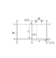
도 2는, 인접 블록의 예측 정보를 사용하여 예측 신호를 생성하는 대상 블록 내의 부분 영역을 설명하기 위한 도면이다. 도 2는, 대상 블록 Bt의 좌측에 인접한 인접 블록 B1을 인접 블록으로 하는 경우를 나타내고 있지만, 본 발명에서의 인접 블록은 대상 블록 상측에 인접한 블록이라도 되고, 또는 좌측 및 상측에 인접한 양쪽의 블록이라도 된다. 또한, 우측과 하측에 인접한 블록이 인접 블록으로서 이용 가능한 경우도 있다.2 is a diagram for explaining a partial area in a target block for generating a prediction signal using prediction information of an adjacent block; 2 shows a case where the adjacent block B1 adjacent to the left side of the target block Bt is used as an adjacent block. However, the adjacent block in the present invention may be a block adjacent to the upper side of the target block, or both blocks adjacent to the left side and the upper side do. There are also cases where blocks adjacent to the right side and the lower side are available as adjacent blocks.
도 2에 나타내는 대상 블록 Bt 및 인접 블록 B1은 8×8 화소의 블록이다. 여기에서는, 좌측 위의 화소 위치(수평 위치, 수직 위치)를 (0, 0), 우측 아래의 화소 위치(수평 위치, 수직 위치)를 (7, 7)로 나타내기로 한다. 도 2에 나타내는 부분 영역 R2는, 인접 블록 B1의 예측 정보를 사용하여 예측 신호를 생성하는 영역이며, 그 수평 방향의 영역 폭은 w이다. 즉, 부분 영역 R2는, (0, 0), (w-1, 0), (0, 7), 및 (w-1, 7)의 4개의 화소 위치에 둘러싸여 있다. 부분 영역 R1은 대상 블록에 부수하는 예측 정보를 사용하여 예측 신호가 생성되는 영역이다.The target block Bt and the adjacent block B1 shown in Fig. 2 are blocks of 8x8 pixels. Here, the pixel position (horizontal position and vertical position) on the upper left side is (0, 0) and the pixel position (horizontal position and vertical position) on the lower right side is represented by (7, 7). The partial region R2 shown in Fig. 2 is a region for generating a prediction signal using the prediction information of the adjacent block B1, and the region width in the horizontal direction is w. That is, the partial area R2 is surrounded by four pixel positions of (0, 0), (w-1, 0), (0, 7), and (w-1, 7). The partial region R1 is an area in which a prediction signal is generated using prediction information attached to a target block.
본 실시예에서는, 설정 가능한 영역 폭은, 1화소 단위로 0∼8 화소까지로 하고 있다. 본 실시예의 영역 폭 결정기(134)는, 설정 가능한 9개의 영역 폭 각각에 대하여, 대상 블록의 예측 신호를 생성하고, 예측 오차의 절대값의 합 또는 제곱의 합이 최소로 되는 영역 폭을 선택한다. 이 처리는, 블록 분할기(104)와 예측 정보 메모리(128)로부터 대상 블록의 화소 신호와 대상 블록 및 인접 블록에 부수하는 예측 정보를 각각 취득하고, 이들 예측 정보와 영역 폭에 기초하여 프레임 메모리(108)에 기억되어 있는 기 재생 신호로부터 대상 블록의 예측 신호를 생성함으로써 실시된다. 영역 폭의 결정 방법 및 설정 가능한 영역 폭의 후보에 대해서는, 특별히 한정되는 것은 아니다. 예를 들면, 설정 가능한 영역 폭은, 2의 배수로 특정되는 화소폭이라도 되며, 1개 이상의 임의의 폭을 채용할 수 있다. 또한, 설정 가능한 영역 폭을 복수 준비하고, 시퀀스 단위나 프레임 단위 또는 블록 단위로 그 선택 정보를 부호화해도 된다.In the present embodiment, the settable area width is 0 to 8 pixels on a pixel-by-pixel basis. The
영역 폭 결정기(134)는, 라인 L134a, 라인 L134b를 통하여 영역 폭 부호화기(136), 예측 신호 생성기(106)에 각각 접속되어 있다. 영역 폭 결정기(134)는, 라인 L134a, 라인 L134b를 경유하여, 영역 폭 부호화기(136), 예측 신호 생성기(106)에, 결정된 영역 폭(영역 폭을 특정하는 정보)을 출력한다.The
영역 폭 부호화기(136)는, 판정기(130)로부터 수취한 판정 결과가 「이용 가능」을 나타내고 있는 경우에, 라인 L134a를 경유하여 수취한 영역 폭을 엔트로피 부호화하여 부호화 데이터를 생성한다. 그리고, 영역 폭 부호화기(136)는, 산술 부호화나 가변길이 부호화 등의 엔트로피 부호화 방식을 이용할 수 있지만, 본 발명은 이들 부호화 방식으로 한정되는 것은 아니다.The
영역 폭 부호화기(136)는, 라인 L136을 통하여 출력 단자(124)에 접속되어 있고, 영역 폭 부호화기(136)에 의해 생성된 부호화 데이터는, 라인 L136을 경유하여 출력 단자(124)에 출력된다.The
예측 신호 생성기(106)는, 라인 L128b를 경유하여 예측 정보 메모리(128)로부터 대상 블록 및 인접 블록에 부수하는 2개의 예측 정보를 수취한다. 또한, 예측 신호 생성기(106)는, 영역 폭 결정기(134)로부터 라인 L134b를 경유하여 영역 폭을 수취하고, 프레임 메모리(108)로부터 라인 L108을 경유하여 기 재생 신호를 수취한다. 예측 신호 생성기(106)는, 수취한 2개의 예측 정보 및 영역 폭을 사용하여, 기 재생 신호로부터 대상 블록의 예측 신호를 생성한다. 예측 신호의 생성 방법의 예에 대해서는 후술한다. 예측 신호 생성기(106)는, 라인 L106을 통하여, 감산기(110)에 접속되어 있다. 예측 신호 생성기(106)에 의해 생성된 예측 신호는, 라인 L106을 경유하여 감산기(110)에 출력된다.The
감산기(110)는, 라인 L104b를 통하여 블록 분할기(104)에 접속되어 있다. 감산기(110)는, 라인 L104b를 경유하여 블록 분할기(104)로부터 수취한 대상 블록의 화상 신호로부터 예측 신호 생성기(106)에 의해 생성된 대상 블록의 예측 신호를 감산한다. 이 감산에 의해 잔차 신호가 생성된다. 이 감산기(110)는 라인 L110을 통하여 변환기(112)에 접속되어 있고, 잔차 신호는 라인 L110을 경유하여 변환기(112)에 출력된다.The
변환기(112)는, 입력된 잔차 신호에 이산 코사인 변환을 적용하여 변환 계수를 생성하는 부분이다. 양자화기(114)는, 변환 계수를 라인 L112를 경유하여 변환기(112)로부터 수취한다. 양자화기(114)는, 변환 계수를 양자화하여 양자화 변환 계수를 생성한다. 양자화 변환 계수 부호화기(122)는, 라인 L114를 경유하여 양자화 변환 계수를 양자화기(114)로부터 수취하고, 상기 양자화 변환 계수를 엔트로피 부호화하여 부호화 데이터를 생성한다. 양자화 변환 계수 부호화기(122)는, 생성한 부호화 데이터를 라인 L122를 경유하여 출력 단자(124)에 출력한다. 그리고, 양자화 변환 계수 부호화기(122)의 엔트로피 부호화로서는, 산술 부호화나 가변길이 부호화를 사용할 수 있지만, 본 발명의 이들 부호화 방식으로 한정되는 것은 아니다.The
출력 단자(124)는, 예측 정보 부호화기(132), 영역 폭 부호화기(136), 및 양자화 변환 계수 부호화기(122)로부터 수취한 부호화 데이터를 함께 외부에 출력한다.The
역양자화기(116)는, 라인 L114b를 경유하여 양자화기(114)로부터 양자화 변환 계수를 수취한다. 역양자화기(116)는, 수취한 양자화 변환 계수를 역양자화하여 변환 계수를 복원한다. 역변환기(118)는, 라인 L116을 경유하여 역양자화기(116)로부터 변환 계수를 수취하고, 상기 변환 계수에 역이산 코사인 변환을 적용하여 잔차 신호(재생 잔차 신호)를 복원한다. 가산기(120)는, 라인 L118을 경유하여 역변환기(118)로부터 재생 잔차 신호를 수취하고, 라인 L106b를 경유하여 예측 신호 생성기(106)로부터 예측 신호를 수취한다. 가산기(120)는, 수취한 재생 잔차 신호와 예측 신호를 가산하여, 대상 블록의 신호(재생 신호)를 재생한다. 가산기(120)에 의해 생성된 재생 신호는, 라인 L120을 경유하여 프레임 메모리(108)에 출력되고, 기 재생 신호로서 프레임 메모리(108)에 기억된다.The inverse quantizer 116 receives the quantization transform coefficients from the
그리고, 본 실시예에서는, 변환기(112)와 역변환기(118)를 사용하고 있지만, 이들 변환기 대신 다른 변환 처리를 사용해도 된다. 또한, 변환기(112) 및 역변환기(118)는 필수적인 것은 아니다. 이와 같이, 후속의 대상 블록의 예측 신호 생성에 사용하기 위해, 부호화된 대상 블록의 재생 신호는, 역처리에 의해 복원되고 프레임 메모리(108)에 기억된다.Although the
또한, 부호화기의 구성은 도 1에 나타낸 것으로 한정되지 않는다. 예를 들면, 판정기(130)와 예측 정보 메모리(128)는, 예측 신호 생성기(106)에 포함되어도 된다. 또한, 영역 폭 결정기(134)도 예측 정보 추정기(126)에 포함되어도 된다.The configuration of the encoder is not limited to that shown in Fig. For example, the
이하, 화상 예측 부호화 장치(100)의 동작과 함께, 일실시예의 화상 예측 부호화 방법을 설명한다. 또한, 판정기(130), 영역 폭 결정기(134), 및 예측 신호 생성기(106)의 동작의 상세한 것에 대해서도 설명한다.Hereinafter, the operation of the image
도 3은, 일실시예에 따른 화상 예측 부호화 방법의 단계를 나타내는 흐름도이다. 도 3에 나타낸 바와 같이, 본 발명의 화상 예측 부호화 방법에 있어서는, 먼저, 단계 S100에서, 블록 분할기(104)가, 부호화 대상의 화상을 복수의 블록으로 분할한다. 이어서, 단계 S102에 있어서, 복수의 블록 중에서 1개의 블록이 부호화의 대상 블록으로서 선택된다.3 is a flowchart showing the steps of the image predictive encoding method according to an embodiment. As shown in Fig. 3, in the image predictive coding method of the present invention, first, in step S100, the
이어서, 단계 S104에 있어서, 예측 정보 추정기(126)가, 대상 블록의 예측 정보를 결정한다. 이 예측 정보는, 계속되는 단계 S106에 있어서, 예측 정보 부호화기(132)에 의해, 부호화된다.Subsequently, in step S104, the
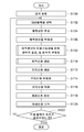
다음으로, 본 발명의 화상 예측 부호화 방법은, 단계 S108로 이행한다. 도 4는, 도 3의 단계 S108를 상세하게 나타낸 흐름도이다. 단계 S108의 처리에서는, 먼저, 단계 S200에 있어서, 판정기(130)에, 대상 블록과 인접 블록에 부수하는 2개의 예측 정보가 입력된다. 이어서, 단계 S202에 있어서, 판정기(130)가, 대상 블록의 예측 신호의 생성에 인접 블록의 예측 정보가 이용 가능한지의 여부를 판정한다.Next, the picture prediction coding method of the present invention moves to step S108. Fig. 4 is a flowchart showing in detail step S108 in Fig. In the process of step S108, first, in step S200, the
도 5는, 도 4의 단계 S202를 상세하게 나타낸 흐름도이다. 도 5에 나타낸 바와 같이, 단계 S202의 처리에서는, 먼저, 단계 S300에서, 판정기(130)가, 대상 블록 및 인접 블록에 부수하는 2개의 예측 정보가 일치하는지의 여부를 판정한다. 단계 S300의 판정이 참(Yes)인 경우, 즉 대상 블록 및 인접 블록에 부수하는 2개의 예측 정보가 일치하는 경우에는, 단계 S302에 있어서, 판정기(130)는, 「이용 불가」를 나타내는 판정 결과를 출력한다.5 is a flowchart showing in detail step S202 of FIG. As shown in Fig. 5, in step S202, first, in step S300, the determining
한편, 단계 S300의 판정이 거짓(No)인 경우에는, 처리는 단계 S304로 이행한다. 단계 S304에 있어서, 판정기(130)는, 인접 블록에 부수하는 예측 정보가 대상 블록의 예측 신호 생성에 이용 가능한 상태인지의 여부를 판정한다. 단계 S304에 있어서의 판정이 참(Yes)인 경우에는, 계속되는 단계 S306에 있어서, 판정기(130)는, 「이용 가능」을 나타내는 판정 결과를 출력한다. 한편, 단계 S304에 있어서의 판정이 거짓(No)인 경우에는, 판정기(130)는, 전술한 단계 S302의 처리를 행한다.On the other hand, if the determination in step S300 is false (No), the process proceeds to step S304. In step S304, the determining
그리고, 단계 S304에 있어서 인접 블록의 예측 정보가 이용 가능한 상태가 아닌 것으로 판정되는 경우로서는, (1) 인접 블록이 화면 밖에 있거나, (2) 대상 블록의 예측 정보와 인접 블록의 예측 정보의 조합을 인정하지 않은 케이스 등이 있다.When it is determined in step S304 that the prediction information of the adjacent block is not in the usable state, (1) the adjacent block is out of the screen, or (2) the combination of the prediction information of the target block and the prediction information of the adjacent block is And cases that are not accepted.
이와 같이 판정기(130)는, 인접 블록에 부수하는 예측 정보를 사용하여 대상 영역의 부분 영역의 예측 신호를 생성해도 될지의 여부의 판정을 미리 정한 룰(rule)에 따라 행한다. 이 룰은, 부호화 장치와 복호 장치가 미리 정보를 공유해 두면, 전송할 필요가 없지만, 부호화하여 전송해도 된다. 예를 들면, 이와 같은 룰을 복수 준비하여, 어느 룰을 적용할지를 프레임 단위나 시퀀스 단위나 블록 단위로 송신하는 방법 등이 있다.Thus, the
다시, 도 4를 참조한다. 도 4에 나타낸 바와 같이, 이어서, 본 발명의 화상 예측 부호화 방법은, 단계 S204로 이행한다. 단계 S204에서는, 영역 폭 결정기(134)가, 판정기(130)의 판정 결과를 참조하여, 상기 판정 결과가 「이용 가능」을 나타내는 판정 결과인지의 여부를 판정한다. 판정기(130)의 판정 결과가 「이용 불가」를 나타내고 있는 경우에는, 단계 S108의 처리는 종료한다.Referring again to FIG. Next, as shown in Fig. 4, the picture prediction coding method of the present invention moves to step S204. In step S204, the
한편, 판정기(130)의 판정 결과가 「이용 가능」을 나타내고 있는 경우에는, 영역 폭 결정기(134)는, 계속되는 단계 S206에 있어서, 인접 블록에 부수하는 예측 정보를 사용하여 예측하는 대상 영역 내의 부분 영역의 영역 폭을 미리 준비한 후보로부터 선택한다. 이어서, 단계 S208에 있어서, 영역 폭 부호화기(136)가, 결정된 영역 폭을 부호화한다.On the other hand, if the judgment result of the judging
이하, 다시 도 3을 참조한다. 도 3에 나타낸 바와 같이, 단계 S108의 후에, 처리는 단계 S110으로 이행한다. 단계 S110에 있어서는, 예측 신호 생성기(106)가, 대상 블록과 인접 블록에 부수하는 2개의 예측 정보, 및 영역 폭 결정기(134)에 의해 결정한 영역 폭을 사용하여, 프레임 메모리(108)에 기억되어 있는 기 재생 신호로부터, 대상 블록의 예측 신호를 생성한다.Hereinafter, referring again to FIG. As shown in Fig. 3, after step S108, the process proceeds to step S110. In step S110, the
이하, 단계 S110에 있어서의 예측 신호 생성기(106)의 상세한 동작의 일례를 설명한다. 도 6은, 도 3의 단계 S110을 상세하게 나타낸 흐름도이다. 도 6은, 도 2에 나타낸 바와 같이, 8×8 화소의 대상 블록 내의 부분 영역 R2의 예측 신호를, 좌측에 인접한 인접 블록에 부수하는 예측 정보를 사용하여 생성하는 경우의 예측 신호 생성기(106)의 동작을 나타내고 있다.Hereinafter, an example of the detailed operation of the
도 6에 나타낸 바와 같이, 단계 S400에 있어서, 먼저, 예측 신호 생성기(106)는, 대상 블록에 부수하는 예측 정보 Pt와 인접 블록에 부수하는 예측 정보 Pn을 취득한다. 이어서, 단계 S402에 있어서, 예측 신호 생성기(106)는, 영역 폭 결정기(134)로부터 영역 폭 w를 취득한다.As shown in Fig. 6, in step S400, the
다음으로, 예측 신호 생성기(106)는, 단계 S404에 있어서, 도 2에 나타낸 대상 블록 내의 부분 영역 R1의 예측 신호를, 예측 정보 Pt 및 영역 폭 w를 사용하여, 기 재생 신호로부터 생성한다. 다음으로, 예측 신호 생성기(106)는, 단계 S406에 있어서, 대상 블록의 부분 영역 R2의 예측 신호를, 예측 정보 Pn 및 영역 폭 w를 사용하여, 기 재생 신호로부터 생성한다. 그리고, 도 2의 예에서는, 영역 폭 w가 0인 경우, 단계 S406은 생략할 수 있다. 또한, 영역 폭 w가 8인 경우, 단계 S404는 생략할 수 있다.Next, in step S404, the
이하에서, 다시 도 3을 참조한다. 도 3에 나타낸 바와 같이, 본 발명의 화상 예측 부호화 방법은, 이어서, 단계 S112로 이행한다. 단계 S112에 있어서, 감산기(110)는, 대상 블록의 화소 신호와 예측 신호를 사용하여, 잔차 신호를 생성한다. 계속되는 단계 S114에 있어서, 변환기(112), 양자화기(114), 및 양자화 변환 계수 부호화기(122)가, 잔차 신호를 변환 부호화하여, 부호화 데이터를 생성한다.In the following, reference is again made to Fig. As shown in Fig. 3, the picture prediction coding method of the present invention then moves to step S112. In step S112, the
이어서, 단계 S116에 있어서, 역양자화기(116) 및 역변환기(118)가, 양자화 변환 계수로부터 재생 잔차 신호를 복원한다. 계속되는 단계 S118에 있어서, 가산기(120)가, 재생 잔차 신호와 예측 신호를 가산함으로써, 재생 신호를 생성한다. 그리고, 단계 S120에 있어서, 재생 신호가, 기 재생 신호로서, 프레임 메모리(108)에 기억된다.Subsequently, in step S116, the inverse quantizer 116 and the inverse transformer 118 restore the reproduction residual signal from the quantized transform coefficients. In the succeeding step S118, the
다음으로, 단계 S122에 있어서, 모든 블록이 대상 블록으로서 처리되었는지의 여부를 체크하고, 모든 블록의 처리가 완료되지 않은 경우에는, 처리되지 않은 블록 중 1개가 대상 블록으로 선택되어, 단계 S102 이후의 처리가 행해진다. 한편, 모든 블록의 처리가 완료된 경우에는, 본 발명의 화상 예측 부호화 방법의 처리는 종료한다.Next, in step S122, it is checked whether or not all the blocks have been processed as the target block. If the processing of all the blocks is not completed, one of the unprocessed blocks is selected as the target block, Processing is performed. On the other hand, when the processing of all the blocks is completed, the processing of the image predictive encoding method of the present invention ends.
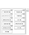
이하, 일실시예에 따른 화상 예측 복호 장치에 대하여 설명한다. 도 7은, 일실시예에 따른 화상 예측 복호 장치를 나타낸 도면이다. 도 7에 나타내는 화상 예측 복호 장치(200)는, 입력 단자(202), 데이터 해석기(204), 역양자화기(206), 역변환기(208), 가산기(210), 출력 단자(212), 양자화 변환 계수 복호기(214), 예측 정보 복호기(216), 영역 폭 복호기(218), 프레임 메모리(108), 예측 신호 생성기(106), 예측 정보 메모리(128), 및 판정기(130)를 구비하고 있다. 여기서, 역양자화기(206), 역변환기(208), 및 양자화 변환 계수 복호기(214)는, 잔차 신호 복호 수단으로서 기능한다. 그리고, 역양자화기(206) 및 역변환기(208)에 의한 복호 수단은, 이들 외의 것들을 사용해도 된다. 또한, 역변환기(208)는 없어도 된다.An image prediction decoding apparatus according to an embodiment will be described below. 7 is a diagram showing an image prediction decoding apparatus according to an embodiment. 7 includes an
이하, 화상 예측 복호 장치(200)의 각 부를 상세하게 설명한다. 입력 단자(202)는, 전술한 화상 예측 부호화 장치(100)(또는 화상 예측 부호화 방법)에 의해 압축 부호화된 압축 데이터를 입력한다. 이 압축 데이터에는, 화상 내의 복수의 블록 각각에 대하여, 잔차 신호를 변환 양자화하여 엔트로피 부호화함으로써 생성된 양자화 변환 계수의 부호화 데이터, 예측 신호를 생성하기 위한 예측 정보의 부호화 데이터, 및 대상 블록에 인접하는 인접 블록에 부수하는 예측 정보를 사용하여 예측 신호를 생성하는 블록 내의 부분 영역의 영역 폭의 부호화 데이터가 포함되어 있다. 본 실시예에서는, 예측 정보에는, 동작 벡터나 참조 화면 번호 등이 포함된다. 입력 단자(202)는 라인 L202를 통하여 데이터 해석기(204)에 접속되어 있다.Each section of the picture
데이터 해석기(204)는, 라인 L202를 경유하여 입력 단자(202)로부터 압축 데이터를 수취한다. 데이터 해석기(204)는, 수취한 압축 데이터를 해석하고, 복호 대상의 대상 블록에 대하여, 압축 데이터를, 양자화 변환 계수의 부호화 데이터, 예측 정보의 부호화 데이터, 영역 폭의 부호화 데이터로 분리한다. 데이터 해석기(204)는, 라인 L204a를 경유하여 영역 폭 복호기(218)에 영역 폭의 부호화 데이터를 출력하고, 라인 L204b를 경유하여 예측 정보의 부호화 데이터를 예측 정보 복호기(216)에 출력하고, 라인 L204c를 경유하여 양자화 변환 계수의 부호화 데이터를 양자화 변환 계수 복호기(214)에 출력한다.The
예측 정보 복호기(216)는, 대상 블록에 부수하는 예측 정보의 부호화 데이터를 엔트로피 복호하여, 예측 정보를 얻는다. 예측 정보 복호기(216)는, 라인 L216을 통하여, 예측 정보 메모리(128)에 접속되어 있다. 예측 정보 복호기(216)에 의해 생성된 예측 정보는, 라인 L216을 경유하여, 예측 정보 메모리(128)에 기억된다. 예측 정보 메모리(128)는, 라인 L128a, 라인 L128b를 통하여, 판정기(130), 예측 신호 생성기(106)에 각각 접속되어 있다.The
판정기(130)는, 도 1의 부호화 장치의 판정기(130)와 동일한 기능을 가지고 있다. 즉, 판정기(130)는, 대상 블록에 부수하는 예측 정보와 대상 블록에 인접하는 인접 블록에 부수하는 예측 정보를 비교하여, 대상 블록의 예측 신호 생성 시에 인접 블록에 부수하는 예측 정보가 이용 가능한지의 여부를 판정한다.The
구체적으로는, 판정기(130)는, 대상 블록 및 인접하는 인접 블록에 부수하는 2개의 예측 정보를 비교하여, 2개의 예측 정보가 일치하는 경우에는, 대상 블록의 예측 신호의 생성에 인접 블록에 부수하는 예측 정보는 이용할 수 없는 것으로 판정한다. 즉, 이 경우에는, 판정기(130)는, 「이용 불가」를 나타내는 판정 결과를 출력한다. 한편, 2개의 예측 정보가 상이한 경우에는, 판정기(130)는, 「이용 가능」을 나타내는 판정 결과를 출력한다. 판정기(130)는, 라인 L130을 통하여 영역 폭 복호기(218)에 접속되어 있다. 판정기(130)에 의한 판정 결과는, 라인 L130을 경유하여 영역 폭 복호기(218)에 출력된다. 그리고, 판정기(130)의 상세한 처리 흐름에 대해서는, 도 5에서 설명되므로 생략한다.Specifically, the
영역 폭 복호기(218)는, L130을 경유하여 수취한 판정기(130)의 판정 결과에 기초하여, 입력된 영역 폭의 부호화 데이터를 엔트로피 복호하여 영역 폭을 복원한다. 즉, 영역 폭 복호기(218)는, 판정 결과가 「이용 가능」을 나타내고 있는 경우에, 영역 폭의 부호화 데이터를 복호하여, 상기 영역 폭을 복원한다. 한편, 판정 결과가 「이용 불가」인 경우에는, 영역 폭의 복원은 행해지지 않아도 된다. 이 영역 폭 복호기(218)는, 라인 L218을 경유하여 예측 신호 생성기(106)에 접속되어 있고, 영역 폭 복호기(218)에 의해 생성된 영역 폭은, 예측 신호 생성기(106)에 라인 L218을 경유하여 출력된다.The
예측 신호 생성기(106)는, 도 1의 부호화 장치의 예측 신호 생성기와 마찬가지의 기능을 가지는 것이다. 즉, 예측 신호 생성기(106)는, 대상 블록에 부수하는 예측 정보와 인접 블록에 부수하는 예측 정보(필요한 경우)와 L218을 경유하여 수취한 영역 폭을 사용하여, 프레임 메모리(108)에 기억되어 있는 기 재생 신호로부터, 복호 대상 블록의 예측 신호를 생성한다. 예측 신호 생성기(106)의 동작의 상세한 것에 대해서는, 도 6에서 설명하였으므로 생략한다. 이 예측 신호 생성기(106)는, 라인 L106을 경유하여 가산기(210)에 접속되어 있다. 예측 신호 생성기(106)는, 생성된 예측 신호를, L106을 경유하여 가산기(210)에 출력한다.The
양자화 변환 계수 복호기(214)는, 라인 L204c를 경유하여 데이터 해석기(204)로부터 양자화 변환 계수의 부호화 데이터를 수취한다. 양자화 변환 계수 복호기(214)는, 수취한 부호화 데이터를 엔트로피 복호하여, 대상 블록의 잔차 신호의 양자화 변환 계수를 복원한다. 양자화 변환 계수 복호기(214)는, 복원한 양자화 변환 계수를 라인 L214를 경유하여 역양자화기(206)에 출력한다.The quantization
역양자화기(206)는, 라인 L214를 경유하여 수취한 양자화 변환 계수를 역양자화하여 변환 계수를 복원한다. 역변환기(208)는, 복원된 변환 계수를 역양자화기(206)로부터 라인 L206을 경유하여 수취하고, 상기 변환 계수에 역이산 코사인 변환을 적용하여, 대상 블록의 잔차 신호(복원 잔차 신호)를 복원한다.The
가산기(210)는, 라인 L208을 경유하여 역변환기(208)로부터 복원 잔차 신호를 수취하고, 예측 신호 생성기(106)로 생성된 예측 신호를 라인 L106을 경유하여 수취한다. 가산기(210)는, 수취한 복원 잔차 신호와 예측 신호를 가산함으로써, 대상 블록의 재생 신호를 생성한다. 이 재생 신호는, 라인 L210을 경유하여 프레임 메모리(108)에 출력되고, 상기 프레임 메모리(108)에 기억된다. 또한, 이 재생 신호는, 출력 단자(212)에도 출력된다. 출력 단자(212)는, 외부(예를 들면, 디스플레이)에, 재생 신호를 출력한다.The
이하, 화상 예측 복호 장치(200)의 동작과 함께, 일실시예에 따른 화상 예측 복호 방법에 대하여 설명한다. 도 8은, 일실시예에 따른 화상 예측 복호 방법의 흐름도이다. 도 8에 나타낸 바와 같이, 본 발명의 화상 예측 복호 방법에서는, 먼저, 단계 S500에 있어서, 입력 단자(202)를 통하여, 압축 데이터가 입력된다. 이어서, 단계 S502에서 처리의 대상이 되는 대상 블록이 선택된다.Hereinafter, an operation of the picture
이어서, 단계 S504에 있어서, 데이터 해석기(204)가, 압축 데이터의 데이터 해석을 행하고, 복호 대상의 대상 블록에 부수하는 예측 정보와, 영역 폭과 양자화 변환 계수의 부호화 데이터를 추출한다. 예측 정보는, 단계 S506에 있어서, 예측 정보 복호기(216)에 의해 복호된다.Next, in step S504, the
다음으로, 처리는, 단계 S508로 이행한다. 도 9는, 도 8의 단계 S508를 상세하게 나타낸 흐름도이다. 도 9에 나타낸 바와 같이, 단계 S508의 처리에서는, 먼저, 단계 S600에 있어서, 판정기(130)에 대상 블록 및 인접 블록에 부수하는 2개의 예측 정보가 입력된다.Next, the process proceeds to step S508. FIG. 9 is a flowchart showing in detail step S508 of FIG. As shown in Fig. 9, in the process of step S508, first, in step S600, two pieces of prediction information attached to the target block and the adjacent block are input to the
다음으로, 단계 S202에 있어서, 판정기(130)가, 인접 블록에 부수하는 예측 정보의 이용 가능성을 판정하여 판정 결과를 출력한다. 이 단계 S202에 있어서의 판정기(130)의 동작은, 도 5에 의해 설명한 동작과 동일하므로, 상세한 설명은 생략한다.Next, in step S202, the
이어서, 단계 S602에 있어서, 판정기(130)의 판정 결과가 「이용 가능」을 나타내는지의 여부가 판정된다. 단계 S602에 있어서의 판정 결과가 참(Yes)인 경우, 즉 인접 블록의 예측 정보가 이용 가능한 경우에는, 단계 S604에 있어서, 영역 폭 복호기(218)가, 영역 폭의 부호화 데이터를 복호하여 대상 블록의 부분 영역(R2)의 영역 폭을 복원한다. 한편, 단계 S602의 판정이 거짓(No)인 경우에는, 단계 S606에 있어서, 영역 폭 복호기(218)가, 대상 블록의 부분 영역(R2)의 영역 폭을 "0"으로 설정한다.Subsequently, in step S602, it is determined whether the determination result of the
이하에서, 다시 도 8을 참조한다. 도 8에 나타낸 바와 같이, 단계 S508의 종료 후에, 처리는 단계 S510으로 이행한다. 단계 S510에 있어서는, 예측 신호 생성기(106)가, 대상 블록 및 인접 블록에 부수하는 2개의 예측 정보(인접 블록의 예측 정보는 필요한 경우에만 이용)와 영역 폭을 사용하여, 기 재생 신호로부터, 복호 대상 블록의 예측 신호를 생성한다. 여기서 단계 S510은 도 6에 설명한 단계 S110과 동일하다.In the following, reference is again made to Fig. As shown in Fig. 8, after the end of step S508, the process proceeds to step S510. In step S510, the
계속되는 단계 S512에 있어서는, 양자화 변환 계수 복호기(214)가, 부호화 데이터로부터 양자화 변환 계수를 복원하여, 역양자화기(206)가 양자화 변환 계수로부터 변환 계수를 복원하고, 역변환기(208)가 변환 계수로부터 재생 잔차 신호를 생성한다.In step S512, the quantization
이어서, 단계 S514에 있어서, 가산기(210)가, 대상 블록의 예측 신호와 재생 잔차 신호를 가산하여, 대상 블록의 재생 신호를 생성한다. 이 재생 신호는, 단계 S516에 있어서, 다음 대상 블록을 재생하기 위한 기 재생 신호로서 프레임 메모리(108)에 기억된다.Subsequently, in step S514, the
그리고, 단계 S518에 있어서 전체 블록의 처리가 완료되지 않은 것으로 판정되는 경우, 즉, 다음 압축 데이터가 있는 경우에는, 단계 S502에 있어서 처리되지 않은 블록이 대상 블록으로 선택되어, 이후의 단계가 반복된다. 한편, 단계 S518에 있어서, 모든 블록의 처리가 완료된 경우에는 처리가 종료된다.If it is determined in step S518 that the processing of the entire block is not completed, that is, if there is next compressed data, the unprocessed block is selected as the target block in step S502, and the subsequent steps are repeated . On the other hand, if all blocks have been processed in step S518, the process ends.
이상, 일실시예에 따른 화상 예측 부호화 장치 및 방법, 및 화상 예측 복호 장치 및 방법을 설명하였으나, 본 발명은, 상기 실시예로 한정되는 것은 아니다. 예를 들면, 상기 실시예에서는, 인접 블록을 대상 블록의 좌측에 인접한 블록이었지만, 인접 블록은 대상 블록 상측에 인접한 블록이라도 된다.Although the image predictive encoding apparatus and method and the image predictive decoding apparatus and method according to the embodiment have been described above, the present invention is not limited to the above embodiments. For example, in the above embodiment, the adjacent block is the block adjacent to the left of the target block, but the adjacent block may be the block adjacent to the upper side of the target block.
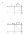
도 10은, 인접 블록의 다른 예를 설명하기 위한 도면이다. 도 10에 나타낸 예에서는, 대상 블록 Bt 및 인접 블록 B2는, 8×8 화소의 블록이며, 전술한 바와 마찬가지로 좌측 위의 화소 위치(수평 위치, 수직 위치)를 (0, 0), 우측 아래의 화소 위치를 (7, 7)로 하고 있다. 부분 영역 R2는, (0, 0), (7, 0), (0, w-1), (7, w-1)의 화소 위치로 둘러싸이는 영역이며, 인접 블록 B2의 예측 정보를 사용하여 예측 신호를 생성할 가능성이 있는 영역이다. 부분 영역 R2의 영역 폭은 w이다.10 is a diagram for explaining another example of the adjacent block. In the example shown in Fig. 10, the target block Bt and the adjacent block B2 are blocks of 8 x 8 pixels, and the pixel positions (horizontal position and vertical position) on the upper left side are (0, 0) The pixel position is (7, 7). The partial area R2 is an area surrounded by the pixel positions of (0, 0), (7, 0), (0, w-1), (7, w-1) And is a region that is likely to generate a prediction signal. The area width of the partial area R2 is w.
도 10에 나타내는 인접 블록 B2에 부수하는 예측 정보를 사용하여, 부분 영역 R2의 예측 신호를 생성하는 경우에는, 도 6의 단계 S404의 x의 범위가 0∼7, y의 범위가 w∼7로 된다. 또한, 도 6의 단계 S406의 x의 범위가 0∼7, y의 범위가 0∼w-1로 된다.When generating the prediction signal of the partial region R2 using the prediction information attached to the adjacent block B2 shown in Fig. 10, the range of x in the step S404 in Fig. 6 is 0 to 7, the range of y is 7 to 7 do. The range of x in step S406 in FIG. 6 is 0 to 7, and the range of y is 0 to w-1.
또한, 인접 블록은, 대상 블록의 좌측 및 상측의 인접한 2개의 블록이라도 되고, 대상 블록마다 2개의 인접 블록 중 어느 하나를 선택할 수 있다. 이 경우, 예측 신호 생성기(106)는, 도 4와 도 10에 관련하여 설명한 예측 처리를 행하는 기능을 가지고, 영역 폭 결정기(134)는, 대상 블록의 부분 영역의 예측에 이용하는 예측 정보를 가지는 인접 블록, 즉 좌측 또는 상측의 인접한 인접 블록을 선택하는 기능을 포함한다. 또한, 영역 폭 부호화기(136)는, 2개의 인접 블록에 부수하는 2개의 예측 정보로부터 대상 영역의 예측 신호의 생성에 이용하는 예측 정보를 가지는 인접 블록을 특정하는 식별 정보를 부호화하는 기능을 포함하고, 영역 폭 복호기(218)는 상기 식별 정보를 복호하는 기능을 포함한다.The adjacent block may be two adjacent blocks on the left side and the upper side of the target block, and any one of two adjacent blocks may be selected for each target block. In this case, the
이하, 좌측 및 상측의 인접한 2개의 블록을 이용하는 경우의 단계 S108에 대하여, 상세하게 설명한다. 도 11은, 도 3의 단계 S108의 다른 예의 상세한 수순을 나타내는 흐름도이다. 도 11에 나타낸 바와 같이, 본 예에서의 단계 S108의 처리에서는, 단계 S700에 있어서, 대상 블록 상측의 인접 블록 및 좌측의 인접 블록에 부수하는 2개의 예측 정보가 판정기(130)에 입력된다.Hereinafter, step S108 in the case of using two adjacent blocks on the left and upper sides will be described in detail. 11 is a flowchart showing a detailed procedure of another example of step S108 in Fig. As shown in Fig. 11, in the process of step S108 in this example, two pieces of prediction information attached to the adjacent block on the upper side of the target block and the adjacent block on the left side are input to the
다음으로, 판정기(130)는, 도 5의 단계 S202에 나타내는 단계에 따라, 대상 블록의 좌측의 인접 블록에 부수하는 예측 정보가, 대상 블록의 부분 영역의 예측 신호의 생성에 이용 가능한지를 판정하고, 판정 결과를 출력한다. 이어서, 단계 S704에 있어서, 판정기(130)에 의한 판정 결과가 「이용 불가」를 나타내고 있는 것으로 판정되는 경우(No의 경우), 즉, 판정 결과가, 좌측의 인접 블록에 부수하는 예측 정보가, 대상 블록의 부분 영역의 예측 신호의 생성에 이용 가능하지 않다는 것을 나타내고 있는 경우에, 계속되는 단계 S202로 진행한다. 판정기(130)는, 도 5의 단계 S202에 나타내는 수순에 따라, 대상 블록 상측의 인접 블록에 부수하는 예측 정보가, 대상 블록의 부분 영역의 예측 신호의 생성에 이용 가능한지를 판정하고, 판정 결과를 출력한다.Next, in accordance with the step shown in step S202 of Fig. 5, the determining
이어서, 단계 S706에 있어서, 판정기(130)에 의한 판정 결과가 「이용 불가」를 나타내고 있는 것으로 판정되는 경우(No의 경우), 즉 판정 결과가, 상측의 인접 블록에 부수하는 예측 정보가, 대상 블록의 부분 영역의 예측 신호의 생성에 이용 가능하지 않다는 것을 나타내고 있는 경우에는, 단계 S108의 처리가 종료된다.Next, in step S706, if it is determined that the determination result by the
한편, 단계 S706에 있어서, 판정기(130)에 의한 판정 결과가 「이용 가능」을 나타내고 있는 것으로 판정되는 경우(Yes의 경우)에, 단계 S708에 있어서, 영역 폭 결정기(134)가, 상측의 인접 블록의 예측 정보를 이용하여 예측 신호를 생성하는 대상 블록의 부분 영역 R2(도 10을 참조)의 영역 폭 w를 결정한다. 이어서, 이 영역 폭 w가, 계속되는 단계 S208에 있어서, 영역 폭 부호화기(136)에 의해 부호화된다.On the other hand, if it is determined in step S706 that the determination result by the
단계 S704로 복귀하고, 한편, 판정기(130)에 의한 판정 결과가 「이용 가능」을 나타내고 있는 것으로 판정되는 경우(Yes의 경우), 계속되는 단계 S202에 있어서, 판정기(130)는, 도 5의 단계 S202에 나타내는 수순에 따라, 대상 블록 상측의 인접 블록에 부수하는 예측 정보가, 대상 블록의 부분 영역의 예측 신호의 생성에 이용 가능한지의 여부를 판정하고, 판정 결과를 출력한다.If the judgment result of the
이어서, 단계 S710에 있어서, 판정기(130)에 의한 판정 결과가 「이용 불가」를 나타내고 있는 것으로 판정되는 경우(No의 경우)에, 계속되는 단계 S712에 있어서, 영역 폭 결정기(134)가, 좌측의 인접 블록의 예측 정보를 이용하여 예측 신호를 생성하는 대상 블록의 부분 영역 R2(도 2를 참조)의 영역 폭 w를 결정한다. 이어서, 이 영역 폭 w가, 계속되는 단계 S208에 있어서, 영역 폭 부호화기(136)에 의해 부호화된다.Subsequently, in step S710, when it is determined that the determination result by the
한편, 단계 S710에 있어서, 판정기(130)에 의한 판정 결과가 「이용 가능」을 나타내고 있는 것으로 판정되는 경우(Yes의 경우)에, 계속되는 단계 S714에 있어서, 좌측의 인접 블록 및 상측의 인접 블록으로부터 예측 신호의 생성에 사용할 예측 정보를 가지는 인접 블록이 선택된다.On the other hand, when it is determined in step S710 that the determination result by the
구체적으로는, 단계 S714에 있어서, 영역 폭 결정기(134)가 대상 블록의 부분 영역의 예측 신호 생성에, 상측의 인접 블록의 예측 정보와 좌측의 인접 블록의 예측 정보 중, 어느 것을 사용할 것인지를 선택한다. 이 선택 방법은 한정되는 것은 아니며, 예를 들면, 영역 폭 결정기(134)는, 도 2 및 도 10에 나타낸 바와 같이 인접 블록 및 부분 영역 R2의 폭을 설정하고, 인접 블록의 예측 정보 및 대상 블록의 예측 정보를 사용하여 대상 블록의 예측 신호를 생성하고, 대상 블록의 예측 오차가 최소로 되는 인접 블록과 영역 폭의 조(組)를 선택한다. 그리고, 계속되는 단계 S716에 있어서, 영역 폭 부호화기(136)가, 선택된 예측 정보를 가지는 인접 블록을 특정하는 식별 정보를, 부호화한다. 이어서, 단계 S718에 있어서, 좌측의 인접 블록이 선택된 것으로 판정되는 경우에는, 처리는 단계 S712로 이행한다. 한편, 단계 S718에 있어서, 좌측의 인접 블록이 선택되지 않은 것으로 판정되는 경우, 즉 상측의 인접 블록이 선택되어 있는 것으로 판정되는 경우에는, 처리는, 단계 S708로 이행한다.Specifically, in step S714, the
도 12는, 도 8의 단계 S508의 다른 예의 상세한 수순을 나타내는 흐름도이며, 도 11의 처리를 사용하는 부호화에 대응하는 복호에 있어서 사용되는 단계를 나타내고 있다. 도 12에 나타낸 바와 같이, 본 예에서는, 먼저, 단계 S800에 있어서, 판정기(130)에 대상 블록의 좌측의 인접 블록에 부수하는 예측 정보, 및 상측의 인접 블록에 부수하는 예측 정보가 입력된다.FIG. 12 is a flowchart showing a detailed procedure of another example of step S508 in FIG. 8, and shows steps used in decoding corresponding to coding using the processing in FIG. As shown in Fig. 12, first, at step S800, predictive information attached to the adjacent block on the left side of the target block and predictive information accompanying the neighboring block on the upper side are input to the
계속되는 2개의 단계에 있어서, 판정기(130)가, 도 5의 단계 S202에 나타내는 수순에 따라, 좌측의 인접 블록에 부수하는 예측 정보의 이용 가능성, 및 상측의 인접 블록에 부수하는 예측 정보의 이용 가능성을 판정하고, 판정 결과를 출력한다.In the following two steps, the
이어서, 단계 S802에 있어서, 영역 폭 복호기(218)가, 판정기(130)의 판정 결과로부터, 2개의 인접 블록 중 어느 한쪽의 인접 블록에 부수하는 예측 정보가 이용 가능한지의 여부를 판정한다. 그리고, 모든 인접 블록에 부수하는 예측 정보가 이용 가능하지 않은 경우에는, 단계 S804에 있어서, 영역 폭 복호기(218)는, 복호 대상 블록의 부분 영역 R2의 영역 폭을 "0"으로 설정하고, 처리를 종료한다.Next, in step S802, the area-
한편, 단계 S802에 있어서, 2개의 인접 블록 중 어느 한쪽의 인접 블록에 부수하는 예측 정보가 이용 가능한 것으로 판정되는 경우에는, 계속되는 단계 S806에 있어서, 영역 폭 복호기(218)가, 판정기(130)의 판정 결과로부터, 2개의 인접 블록에 부수하는 예측 정보가 모두 이용 가능한지의 여부를 판정한다. 2개의 인접 블록의 예측 정보가 모두 이용 가능한 경우에는, 계속되는 단계 S808에 있어서, 영역 폭 복호기(218)는, 부호화 데이터로부터 인접 블록의 식별 정보를 복호하고, 단계 S812로 진행한다.On the other hand, if it is determined in step S802 that prediction information accompanying one of the two neighboring blocks is available, the area-
한편, 단계 S806에 있어서, 2개의 인접 블록 중 어느 한쪽의 인접 블록에 부수하는 예측 정보가 이용 가능한 것으로 판정된 경우에는, 계속되는 단계 S810에 있어서, 영역 폭 복호기(218)는, 판정기(130)의 판정 결과에 기초하여, 2개의 인접 블록에 부수하는 예측 정보 중 한쪽을 선택하고, 단계 S812로 진행한다. 그리고, 단계 S812에 있어서, 영역 폭 복호기(218)는, 영역 폭의 값을 복호한다.On the other hand, if it is determined in step S806 that prediction information accompanying one of the two adjacent blocks is available, the area-
그리고, 대상 블록의 좌측의 인접 블록에 부수하는 예측 정보와 상측의 인접 블록에 부수하는 예측 정보를 모두 이용하여, 대상 블록의 예측 신호가 생성되어도 된다. 이 경우에는, 영역 폭 부호화기(136)는, 2개의 인접 블록에 부수하는 2개의 예측 정보와 2개의 영역 폭의 조를 모두 부호화하는 기능을 가지고, 영역 폭 복호기(218)는 2개의 예측 정보와 2개의 영역 폭의 조를 복호하는 기능을 가진다. 또한, 이 경우에는, 도 13에 나타낸 바와 같이, 대상 블록 Bt 내의 4개의 부분 영역 R1∼R4의 예측 신호가 개별적으로 생성된다.The prediction signal of the target block may be generated using both the prediction information associated with the adjacent block on the left side of the target block and the prediction information associated with the adjacent adjacent block on the upper side. In this case, the area-
그러므로, 예측 신호 생성기(106)는, 좌측의 인접 블록 B1에 부수하는 예측 정보를 사용하여 부분 영역 R2의 예측 신호를 생성하고, 상측의 인접 블록 B2에 부수하는 예측 정보를 사용하여 부분 영역 R3의 예측 신호를 생성한다. 또한, 예측 신호 생성기(106)는, 부분 영역 R4의 예측 신호를 생성하는 기능을 가질 필요가 있다. 부분 영역 R4의 예측 방법은, 룰을 미리 결정해 두면 되므로 본 발명에서는 한정되지 않는다. 예를 들면, 좌측의 인접 블록에 부수하는 예측 정보에 기초하여 생성되는 부분 영역 R4의 예측 신호와, 상측의 인접 블록에 부수하는 예측 정보에 기초하여 생성되는 부분 영역 R4의 예측 신호를 화소 단위로 평균화하는 방법이나, 좌상측의 인접 블록에 부수하는 예측 정보에 기초하여 부분 영역 R4의 예측 신호를 생성하는 방법 등이 있다. 또한, 좌측 및 상측의 인접 블록에 부수하는 예측 정보 등의 주위의 복호가 종료된 데이터를 이용하여 상측과 좌측의 인접 블록에 속하는 예측 정보로부터 자동적으로 선택하는 방법이나, 선택 정보를 보내는 방법 등도 채용할 수 있다.Therefore, the
본 발명에서는, 또한 하기와 같은 변형이 가능하다.In the present invention, the following modifications are possible.
(블록의 형상)(Shape of block)
상기 설명에서는, 대상 블록 내의 부분 영역은 항상 직사각형이었지만, 도 14의 (a)에 나타내는 대상 블록 Bt 내의 부분 영역 R1 및 R2나, 도 14의 (b)에 나타내는 대상 블록 Bt 내의 부분 영역 R1 및 R2와 같이, 임의의 형상을 가지는 부분 영역이 사용되어도 된다. 이와 같은 경우에는, 영역 폭에 더하여 형상 정보가 송부되는 경우가 있다.In the above description, the partial area in the target block is always rectangular, but partial areas R1 and R2 in the target block Bt shown in FIG. 14A and partial areas R1 and R2 in the target block Bt shown in FIG. A partial region having an arbitrary shape may be used. In such a case, shape information may be sent in addition to the area width.
(블록 사이즈)(Block size)
상기 설명에서는, 블록 사이즈는 고정 사이즈였지만, 도 15의 (a)∼(c)에 나타낸 바와 같이, 대상 블록 Bt와 인접 블록 B1의 사이즈가 상이해도 된다. 이와 같은 경우에는, 도 15의 (a)∼(c)에 나타낸 바와 같이, 대상 블록 Bt에 있어서의 부분 영역 R1∼R3의 형상으로서는, 각종 형상을 사용할 수 있다. 상황에 따라 구성되는 부분 영역이 결정되어도 되고, 인접 블록을 지시하는 정보를 복수의 후보로부터 선택하여 명시적으로 부호화해도 된다. 또한, 미리 규칙(예를 들면, 영역 폭을 선택하는 단위를 블록 사이즈가 작은 쪽으로 맞추거나 하는 등)을 결정해 두어도 된다.In the above description, the block size is a fixed size, but as shown in Figs. 15A to 15C, the sizes of the target block Bt and the adjacent block B1 may be different. In such a case, as shown in Figs. 15A to 15C, various shapes can be used as the shapes of the partial regions R1 to R3 in the target block Bt. A partial area configured according to the situation may be determined, or the information indicating the adjacent block may be explicitly encoded by selecting from a plurality of candidates. It is also possible to determine in advance rules (for example, to set the unit for selecting the area width to a smaller block size).
*(영역 폭 부호화기 및 복호기)* (Domain width encoder and decoder)
영역 폭 부호화기에 있어서는, 영역 폭의 값 자체가 아니라, 영역 폭을 특정하기 위한 정보가 부호화되어도 된다. 또한, 영역 폭 복호기에서는, 영역 폭의 값자체가 아니라, 부호화 데이터로부터 영역 폭을 특정하기 위한 정보를 복호하여, 상기 영역 폭을 특정하기 위한 정보에 기초하여 영역 폭의 값을 복원해도 된다. 예를 들면, 영역 폭 부호화기는, 대상 블록 내의 부분 영역의 영역 폭의 값의 후보를 복수 준비하고, 그 식별 정보를 부호화해도 된다. 영역 폭 복호기는, 복호한 식별 정보에 기초하여 영역 폭의 값을 복원해도 된다. 후보로 되는 영역 폭은 부호화기와 복호기에서 미리 결정해 두어도 되고, 시퀀스 단위나 프레임 단위로 송신해도 된다. 또한, 영역 폭 부호화기는, 대상 블록 내의 부분 영역의 영역 폭의 값과 인접 블록의 영역 폭과의 차분값을 부호화해도 된다. 이 경우에는, 영역 폭 복호기는, 이미 복호되어 있는 인접 블록의 영역 폭의 값과 부호화 데이터로부터 복호된 상기 차분치를 가산함으로써, 대상 블록 내의 부분 영역의 영역 폭의 값을 복원할 수 있다. 혹은, 영역 폭 부호화기는, 대상 블록의 부분 영역의 영역 폭이 인접 블록의 영역 폭과 동일할 것을 지시하는 정보를 부호화해도 된다. 대상 블록의 부분 영역의 영역 폭이 인접 블록의 영역 폭과 동일할 것을 지시하는 정보가 복호된 경우에는, 영역 폭 복호기는, 상기 인접 블록의 영역 폭을 대상 블록의 부분 영역의 영역 폭으로서 사용할 수 있다. 이 때, 대상 블록의 부분 영역의 영역 폭이 인접 블록의 영역 폭과 상이할 것을 지시하고, 또한 영역 폭의 값 또는 영역 폭을 특정하기 위한 정보를 송신해도 된다. 대상 블록의 부분 영역의 영역 폭이 인접 블록의 영역 폭과 상이할 것을 지시하는 정보가 복호된 경우에는, 영역 폭 복호기는, 또한 부호화 데이터로부터 영역 폭의 값 또는 영역 폭을 특정하기 위한 정보를 복호하고, 상기 영역 폭을 특정하기 위한 정보에 기초하여 영역 폭의 값을 복원해도 된다. 또한, 영역 폭 부호화기는, 영역 폭을 특정하기 위한 1이상의 정보 아이템을 부호화해도 된다. 즉, 영역 폭을 일의적으로 특정할 수 있는 1이상의 정보 아이템(예를 들면, 1이상의 비트)이 부호화되어도 된다. 이 경우에는, 영역 폭 복호기는, 부호화 데이터로부터 1이상의 정보 아이템을 복호하여, 상기 1이상의 정보 아이템에 따라, 영역 폭을 복원할 수 있다.In the area width encoder, not only the value of the area width itself, but also information for specifying the area width may be coded. Further, in the area-width decoder, information for specifying the area width from the encoded data may be decoded instead of the area width value itself, and the value of the area width may be restored based on the information for specifying the area width. For example, the area width encoder may prepare a plurality of candidates of the value of the area width of the partial area in the target block, and encode the identification information. The area width decoder may restore the value of the area width based on the decoded identification information. The candidate region width may be determined in advance in the encoder and the decoder, or may be transmitted in units of a sequence or a frame. The area width encoder may encode the difference value between the value of the area width of the partial area in the target block and the area width of the adjacent block. In this case, the area-width decoder can restore the value of the area width of the partial area in the target block by adding the value of the area width of the adjacent block already decoded and the difference value decoded from the encoded data. Alternatively, the area width encoder may encode information indicating that the area width of the partial area of the target block is equal to the area width of the adjacent block. When the information indicating that the area width of the partial area of the object block is equal to the area width of the adjacent block is decoded, the area width decoder can use the area width of the adjacent block as the area width of the partial area of the object block have. At this time, information for indicating that the area width of the partial area of the object block is different from the area width of the adjacent block, and for specifying the value of the area width or the area width may be transmitted. When the information indicating that the area width of the partial area of the target block is different from the area width of the adjacent block is decoded, the area width decoder also decodes information for specifying the value of the area width or the area width from the encoded data And the value of the area width may be restored based on the information for specifying the area width. The area width encoder may encode one or more information items for specifying the area width. That is, one or more information items (for example, one or more bits) capable of uniquely specifying the area width may be coded. In this case, the domain-wide decoder may decode one or more information items from the encoded data, and restore the domain-wide based on the one or more information items.
(변환기, 역변환기)(Converter, inverse converter)
잔차 신호의 변환 처리는, 고정 블록 사이즈로 행해도 된다. 또한, 부분 영역에 맞춘 사이즈에 대상 영역을 재분할하고, 재분할에 의해 생성된 각각의 영역에 대하여 변환 처리를 행해도 된다.The conversion process of the residual signal may be performed with a fixed block size. It is also possible to re-divide the target area into a size matched to the partial area, and perform conversion processing for each area generated by re-division.
(판정기에 대하여)(With respect to the judging device)
인접 블록에 부수하는 예측 정보의 이용이 가능한 인접 블록은, 대상 블록 상측의 인접 블록과 좌측의 인접 블록으로 한정되지 않는다. 예를 들면, 예측 정보를 1블록열만큼 먼저 부호화해 두면, 대상 블록에 인접하는 4블록 모두를 인접 블록으로 하고, 이들에 부수하는 예측 정보를 대상 블록의 예측 신호의 생성에 사용할 수 있다.The adjacent block that can use the prediction information attached to the adjacent block is not limited to the adjacent block on the upper side of the target block and the adjacent block on the left side. For example, if the prediction information is coded by one block column first, all four blocks adjacent to the target block are made to be adjacent blocks, and the prediction information accompanying them can be used for generation of the prediction signal of the target block.
또한, 화면 내의 전체 블록의 예측 정보를 먼저 부호화해 두면, 각 대상 블록의 예측 신호는 주위의 4블록과 대상 블록에 부수하는 합계 5개(좌측 위, 좌측 아래, 우측 위, 우측 아래를 포함하면 9개)의 예측 정보를 사용하여 자유롭게 구성할 수도 있다.If the predictive information of all the blocks in the picture is coded first, the prediction signal of each target block includes five neighboring blocks and a total of five blocks (including the upper left, lower left, upper right, and lower right) 9 pieces of prediction information) can be freely configured.
또한, 대상 블록과 인접 블록이 동일한 예측 정보를 가지는 경우에 부분 영역을 형성해도 부호화·복호 처리는 파탄(破綻)되지 않으므로, 판정기가 포함되지 않은 구성이라도 본 발명의 예측 신호 생성 처리는 실현될 수 있다.Further, even if the partial block is formed when the target block and the adjacent block have the same prediction information, the encoding / decoding process is not broken, so that the prediction signal generating process of the present invention can be realized even when the determination device is not included have.
(판정기의 판정에 대하여)(Regarding judgment of judging machine)
상기 설명에서는, 판정기(130)가 인접 블록에 부수하는 예측 정보의 이용 가능성을 판정하기 위해 미리 정한 룰로서, 인접 블록에 부수하는 예측 정보가 대상 블록에 부수하는 예측 정보와 일치하는 경우나 인접 블록의 예측 정보가 이용 가능한 상태가 아닌 것으로 판정되는 경우에는, 인접 블록에 부수하는 예측 정보를 이용할 수 없는 것으로 판정하고 있다. 후자에 대해서는, 인접 블록이 화면 내 예측에 의해 예측되고, 대상 블록이 화면간에 의해 예측되는 경우, 및 이와 반대의 경우에는, 인접 블록에 부수하는 예측 정보를 이용할 수 없는 것으로 판정해도 된다. 또한, 인접 블록의 동작 벡터와 대상 블록의 동작 벡터와의 사이의 차이가 임계값보다 큰 경우에, 인접 블록에 부수하는 예측 정보를 이용할 수 없는 것으로 판정해도 된다. 또한, 인접 블록과 대상 블록의 블록 사이즈가 서로 상이한 경우에는, 인접 블록에 부수하는 예측 정보를 이용할 수 없는 것으로 판정해도 된다. 또한, 상기 설명에서는, 인접 블록과 대상 블록에 부수하는 예측 정보를 비교하고 있지만, 2개의 예측 정보에 기초하여 생성되는 예측 신호가 동일한지 혹은 상이한지의 조건으로 인접 블록에 부수하는 예측 정보의 이용 가능성을 판정해도 된다.In the above description, when the
(예측 정보)(Prediction information)
상기 설명에서는, 예측 신호의 생성 방법으로서 화면간 예측(동작 벡터와 참조 화면 정보)을 설명하였으나, 본 발명은 이 예측 방법으로 한정되는 것은 아니다. 화면 내 예측이나, 휘도 보상, 양방향 예측, 후방 예측 등의 예측 방법을, 본 발명의 예측 신호 생성 처리에 적용할 수 있다. 이 경우, 모드 정보나 휘도 보상 파라미터 등이 예측 정보에 포함된다.In the above description, inter-picture prediction (motion vector and reference picture information) has been described as a method of generating a prediction signal, but the present invention is not limited to this prediction method. Prediction methods such as intra prediction, luminance compensation, bidirectional prediction, and backward prediction can be applied to the prediction signal generation processing of the present invention. In this case, the prediction information includes mode information, a luminance compensation parameter, and the like.
(색 신호)(Color signal)
상기 설명에서는, 색 포맷에 대하여 특별히 언급하지 않았지만, 색 신호 또는 색차 신호에 대해서도, 휘도 신호와 개별적으로 예측 신호의 생성 처리를 행해도 된다. 또한, 색 신호 또는 색차 신호의 예측 신호의 생성 처리를, 휘도 신호의 처리와 연동하여 행해도 된다. 후자의 경우에, 색 신호의 해상도가 휘도 신호보다 낮은 경우(예를 들면, 해상도가 세로 방향과 가로 방향으로 절반)에는, 휘도 신호에 있어서의 영역 폭을 제한(예를 들면, 짝수값)하거나, 또는 휘도 신호의 영역 폭으로부터 색 신호의 영역 폭으로의 변환식을 결정해 두면 된다.In the above description, the color signal or color difference signal may be generated separately from the luminance signal, although the color format is not particularly mentioned. The generation processing of the prediction signal of the color signal or the color difference signal may be performed in conjunction with the processing of the luminance signal. In the latter case, when the resolution of the color signal is lower than that of the luminance signal (for example, the resolution is halved in the vertical direction and the horizontal direction), the area width in the luminance signal is limited (for example, , Or a conversion equation from the area width of the luminance signal to the area width of the color signal may be determined.
(블록 노이즈 제거 처리)(Block noise removal processing)
상기에서는 언급하지 않았지만, 재생 화상에 대하여 블록 노이즈 제거 처리를 행하는 경우에는, 부분 영역의 경계 부분에 대하여 노이즈 제거 처리를 행하면 된다.Although not mentioned above, in the case of performing the block noise removing process on the reproduced image, the noise removing process may be performed on the boundary portion of the partial area.
이하에서, 컴퓨터를 화상 예측 부호화 장치(100)로서 동작시키기 위한 화상 예측 부호화 프로그램, 및 컴퓨터를 화상 예측 복호 장치(200)로서 동작시키기 위한 화상 예측 복호 프로그램에 대하여 설명한다.An image predictive encoding program for causing a computer to operate as the image
도 16은, 일실시예에 따른 화상 예측 부호화 프로그램을, 기록 매체와 함께 나타낸 도면이다. 도 17은, 일실시예에 따른 화상 예측 복호 프로그램을, 기록 매체와 함께 나타낸 도면이다. 도 18은, 기록 매체에 기록된 프로그램을 실행하기 위한 컴퓨터의 하드웨어 구성을 나타낸 도면이다. 도 19는, 기록 매체에 기억된 프로그램을 실행하기 위한 컴퓨터의 사시도이다.16 is a diagram showing an image predictive encoding program according to an embodiment together with a recording medium. 17 is a diagram showing an image prediction decoding program according to an embodiment together with a recording medium. 18 is a diagram showing a hardware configuration of a computer for executing a program recorded on a recording medium. 19 is a perspective view of a computer for executing a program stored in a recording medium.
도 16에 나타낸 바와 같이, 화상 예측 부호화 프로그램 P100은, 기록 매체(10)에 저장되어 제공된다. 또한, 도 17에 나타낸 바와 같이, 화상 예측 복호 프로그램 P200도, 기록 매체(10)에 저장되어 제공된다. 그리고, 기록 매체(10)로서는, 플로피디스크, CD-ROM, DVD, 또는 ROM 등의 기록 매체, 또는 반도체 메모리 등이 예시된다.As shown in Fig. 16, the picture prediction coding program P100 is stored in the
도 18에 나타낸 바와 같이, 컴퓨터(30)는, 플로피디스크 드라이버 장치, CD-ROM 드라이브 장치, DVD 드라이브 장치 등의 판독 장치(12)와, 오퍼레이팅시스템을 상주시킨 작업용 메모리(RAM)(14)와, 기록 매체(10)에 기억된 프로그램을 기억하는 메모리(16)와, 디스플레이와 같은 표시 장치(18)와, 입력 장치인 마우스(20) 및 키보드(22)와, 데이터 등의 송수신을 행하기 위한 통신 장치(24)와, 프로그램의 실행을 제어하는 CPU(26)를 구비하고 있다. 컴퓨터(30)는, 기록 매체(10)가 판독 장치(12)에 삽입되면, 판독 장치(12)로부터 기록 매체(10)에 저장된 화상 예측 부호화 프로그램 P100에 액세스 가능해져, 상기 프로그램 P100에 의해, 화상 예측 부호화 장치(100)로서 동작할 수 있게 된다. 또한, 컴퓨터(30)는, 기록 매체(10)가 판독 장치(12)에 삽입되면, 판독 장치(12)로부터 기록 매체(10)에 저장된 화상 예측 복호 프로그램 P200에 액세스 가능해져, 상기 프로그램 P200에 의해, 화상 예측 복호 장치(200)로서 동작할 수 있게 된다.18, the
도 19에 나타낸 바와 같이, 화상 예측 부호화 프로그램 P100 및 화상 예측 복호 프로그램 P200은, 반송파(搬送波)에 중첩된 컴퓨터 데이터 신호(40)로서 네트워크를 통하여 제공되는 것이라도 된다. 이 경우, 컴퓨터(30)는, 통신 장치(24)에 의해 수신된 화상 예측 부호화 프로그램 P100 또는 화상 예측 복호 프로그램 P200을 메모리(16)에 저장하여, 프로그램 P100 또는 P200을 실행할 수 있다.As shown in Fig. 19, the picture predictive encoding program P100 and the picture predictive decoding program P200 may be provided via a network as a computer data signal 40 superimposed on a carrier wave (carrier wave). In this case, the
도 16에 나타낸 바와 같이, 화상 예측 부호화 프로그램 P100은, 블록 분할 모듈 P104, 예측 신호 생성 모듈 P106, 기억 모듈 P108, 감산 모듈 P110, 변환 모듈 P112, 양자화 모듈 P114, 역양자화 모듈 P116, 역변환 모듈 P118, 가산 모듈 P120, 양자화 변환 계수 부호화 모듈 P122, 예측 정보 추정 모듈 P126, 예측 정보 기억 모듈 P128, 판정 모듈 P130, 영역 폭 결정 모듈 P134, 예측 정보 부호화 모듈 P132, 영역 폭 결정 모듈 P134, 및 영역 폭 부호화 모듈 P136을 구비하고 있다.16, the picture prediction coding program P100 includes a block division module P104, a prediction signal generation module P106, a storage module P108, a subtraction module P110, a transformation module P112, a quantization module P114, an inverse quantization module P116, an inverse transformation module P118, The prediction module C123, the addition module P120, the quantization transform coefficient coding module P122, the prediction information estimation module P126, the prediction information storage module P128, the judgment module P130, the area width determination module P134, the prediction information coding module P132, the area width determination module P134, P136.
전술한 각 모듈이 실행되는 것에 의해 실현되는 기능은, 전술한 화상 예측 부호화 장치(100)의 기능과 동일하다. 즉, 화상 예측 부호화 프로그램 P100의 각 모듈의 기능은, 블록 분할기(104), 예측 신호 생성기(106), 프레임 메모리(108), 감산기(110), 변환기(112), 양자화기(114), 역양자화기(116), 역변환기(118), 가산기(120), 양자화 변환 계수 부호화기(122), 예측 정보 추정기(126), 예측 정보 메모리(128), 판정기(130), 예측 정보 부호화기(132), 영역 폭 결정기(134), 및 영역 폭 부호화기(136)의 기능과 동일하다.The function realized by executing each of the above-described modules is the same as the function of the image
화상 예측 복호 프로그램 P200은, 데이터 해석 모듈 P204, 양자화 변환 계수 복호 모듈 P214, 예측 정보 복호 모듈 P216, 영역 폭 복호 모듈 P218, 예측 정보 기억 모듈 P128, 판정 모듈 P130, 역양자화 모듈 P206, 역변환 모듈 P208, 가산 모듈 P210, 예측 신호 생성 모듈 P106, 및 기억 모듈 P108을 구비하고 있다.The picture prediction decoding program P200 includes a data analysis module P204, a quantization transformation coefficient decoding module P214, a prediction information decoding module P216, a domain width decoding module P218, a prediction information storage module P128, a judgment module P130, an inverse quantization module P206, An addition module P210, a prediction signal generation module P106, and a storage module P108.
전술한 각 모듈이 실행되는 것에 의해 실현되는 기능은, 전술한 화상 예측 복호 장치(200)의 각 구성 요소와 동일하다. 즉, 화상 예측 복호 프로그램 P200의 각 모듈의 기능은, 데이터 해석기(204), 양자화 변환 계수 복호기(214), 예측 정보 복호기(216), 영역 폭 복호기(218), 예측 정보 메모리(128), 판정기(130), 역양자화기(206), 역변환기(208), 가산기(210), 예측 신호 생성기(106), 및 프레임 메모리(108)의 기능과 동일하다.The functions realized by the execution of each module described above are the same as the respective components of the image
이상으로, 본 발명을 그 실시예에 의해 상세하게 설명하였다. 그러나, 본 발명은 상기 실시예로 한정되는 것은 아니다. 본 발명은, 그 요지를 벗어나지 않는 범위에서 다양한 변형이 가능하다.The present invention has been described in detail by way of examples. However, the present invention is not limited to the above embodiments. The present invention can be modified in various ways without departing from the spirit thereof.
100: 화상 예측 부호화 장치
102: 입력 단자
104: 블록 분할기
106: 예측 신호 생성기
108: 프레임 메모리
110: 감산기
112: 변환기
114: 양자화기
116: 역양자화기
118: 역변환기
120: 가산기
122: 양자화 변환 계수 부호화기
124: 출력 단자
126: 예측 정보 추정기
128: 예측 정보 메모리
130: 판정기
132: 예측 정보 부호화기
134: 영역 폭 결정기
136: 영역 폭 부호화기
200: 화상 예측 복호 장치
202: 입력 단자
204: 데이터 해석기
206: 역양자화기
208: 역변환기
210: 가산기
212: 출력 단자
214: 양자화 변환 계수 복호기
216: 예측 정보 복호기
218: 영역 폭 복호기100: Picture predictive coding apparatus 102: Input terminal
104: block divider 106: prediction signal generator
108: frame memory 110:
112: converter 114: quantizer
116: Inverse quantizer 118: Inverse transformer
120: adder
122: quantization transform coefficient encoder 124: output terminal
126: prediction information estimator 128: prediction information memory
130: Estimator 132: prediction information encoder
134: area width determiner 136: area width encoder
200: picture prediction decoding apparatus 202: input terminal
204: Data interpreter 206: Inverse quantizer
208: Inverse transformer 210:
212: output terminal 214: quantization transform coefficient decoder
216: Prediction information decoder 218: Region width decoder
Claims (8)
화상을 복수의 영역으로 분할하여 부호화된 압축 데이터 중에서, 대상 영역의 예측 신호의 생성에 사용하기 위한 영역을 특정하는 식별 정보의 부호화 데이터와, 잔차 신호의 부호화 데이터를 추출하는 제1 단계;
상기 식별 정보의 부호화 데이터로부터 복호되는 식별 정보에 기초하여, 상기 대상 영역에 인접하는 복수의 인접 영역 중 하나의 인접 영역을 특정하고, 특정한 상기 인접 영역에서의, 화면간 예측 방법을 특정하는 모드 정보, 참조 화면 번호, 및 동작 벡터를 이용하여, 기 재생 신호로부터 상기 대상 영역의 예측 신호를 생성하는 제2 단계;
상기 잔차 신호의 부호화 데이터로부터 상기 대상 영역의 재생 잔차 신호를 복원하는 제3 단계;
상기 대상 영역의 예측 신호와 상기 재생 잔차 신호에 기초하여, 상기 대상 영역의 재생 신호를 생성하는 제4 단계; 및
상기 대상 영역의 재생 신호를 기 재생 신호로서 기억하는 제5 단계
를 포함하는 화상 예측 복호 방법.An image prediction decoding method of an image prediction decoding apparatus,
A first step of extracting encoded data of identification information and encoded data of a residual signal that specifies an area to be used for generation of a prediction signal of a target area from compressed data obtained by dividing an image into a plurality of areas;
A mode information determining unit that identifies one of the plurality of adjacent areas adjacent to the target area based on the identification information decoded from the encoded data of the identification information and specifies mode information A second step of generating a prediction signal of the target area from a basic playback signal using a reference picture number and a motion vector;
A third step of restoring a reproduction residual signal of the target area from encoded data of the residual signal;
A fourth step of generating a reproduction signal of the target area based on the prediction signal of the target area and the reproduction residual signal; And
And a fifth step of storing the reproduction signal of the target area as a pre-
And decoding the predicted image.
부분 영역 정보의 부호화 데이터를 추출하는 단계와;
상기 부분 영역 정보의 부호화 데이터를 복호하여, 상기 부분 영역 정보를 복원하는 단계와;
상기 식별 정보의 부호화 데이터를 복호하여 식별 정보를 복원하는 단계
를 더 포함하고,
상기 부분 영역 정보로부터, 상기 대상 영역을 제1 부분 영역 및 제2 부분 여역으로 분할하는 것이 특정되는 경우에, 상기 제1 부분 영역의 상기 예측 신호의 생성에서, 상기 대상 영역에 인접하는 복수의 인접 영역 중 상기 식별 정보에 기초하여 상기 하나의 인접 영역이 선택되는, 화상 예측 복호 방법.The method according to claim 1,
Extracting encoded data of partial area information;
Decoding the encoded data of the partial area information and restoring the partial area information;
Decoding the encoded data of the identification information and restoring the identification information
Further comprising:
When it is specified from the partial area information that the object area is divided into the first partial area and the second partial area, in generating the prediction signal of the first partial area, a plurality of adjacent And the one adjacent region is selected based on the identification information in the region.
상기 제1 부분 영역의 상기 예측 신호의 생성에서 사용하는 상기 인접 영역으로서, 상기 대상 영역에 인접하는 복수의 인접 영역 중, 화면내 예측에 의해 예측된 인접 영역을 제외한 인접영역이 선택되는, 화상 예측 복호 방법.3. The method of claim 2,
In which the adjacent region excluding the adjacent region predicted by the intra prediction is selected from the plurality of adjacent regions adjacent to the target region as the adjacent region used in the generation of the prediction signal in the first partial region, Decoding method.
상기 식별 정보의 부호화 데이터로부터 복호되는 식별 정보에 기초하여, 상기 대상 영역에 인접하는 복수의 인접 영역 중 하나의 인접 영역을 특정하고, 특정한 상기 인접 영역에서의, 화면간 예측을 특정하는 모드 정보, 참조 화면 번호, 및 동작 벡터를 이용하여, 기 재생 신호로부터 상기 대상 영역의 예측 신호를 생성하는 예측 신호 생성 수단;
상기 잔차 신호의 부호화 데이터로부터 상기 대상 영역의 재생 잔차 신호를 복원하는 잔차 신호 복원 수단;
대상 영역의 예측 신호와 상기 재생 잔차 신호에 기초하여, 상기 대상 영역의 재생 신호를 생성하는 재생 신호 생성 수단; 및
상기 대상 영역의 재생 신호를 기 재생 신호로서 기억하는 기억 수단
을 포함하는 화상 예측 복호 장치.Extracting means for extracting, from among the compressed data obtained by dividing an image into a plurality of regions, encoded data of identification information for specifying an area to be used for generating a prediction signal of the target region and encoded data of the residual signal;
Mode information for identifying one of the plurality of neighboring areas adjacent to the target area based on the identification information decoded from the encoded data of the identification information and specifying the inter-picture prediction in the specific neighboring area, Prediction signal generating means for generating a prediction signal of the target area from the basic reproduction signal by using the reference picture number and the motion vector;
Residual signal restoring means for restoring the reproduction residual signal of the target area from the encoded data of the residual signal;
Reproduction signal generating means for generating a reproduction signal of the target area based on the prediction signal of the target area and the reproduction residual signal; And
A storage means for storing a reproduction signal of the target area as a pre-
And decodes the decoded picture.
입력 화상을 복수의 영역으로 분할하는 영역 분할 단계;
식별 정보에 기초하여, 상기 복수의 영역에서, 대상 영역에 인접하는 복수의 인접 영역 중 하나의 인접 영역을 특정하고, 특정한 상기 인접 영역에서의, 화면간 예측 방법을 특정하는 모드 정보, 참조 화면 번호, 및 동작 벡터를 이용하여, 기 재생 신호로부터 상기 대상 영역의 예측 신호를 생성하는 예측 신호 생성 단계;
상기 대상 영역의 예측 신호와 상기 대상 영역의 화소 신호 간의 잔차 신호를 생성하는 잔차 신호 생성 단계;
상기 잔차 신호를 부호화하는 잔차 신호 부호화 단계;
상기 잔차 신호의 부호화 데이터를 복호하는 것에 의해 재생 잔차 신호를 생성하는 잔차 신호 복원 단계;
상기 예측 신호와 상기 재생 잔차 신호를 가산하는 것에 의해 상기 대상 영역의 재생 신호를 생성하는 가산 단계; 및
상기 대상 영역의 재생 신호를 상기 기 재생 신호로서 기억하는 기억 단계
를 포함하는 화상 예측 부호화 방법. A picture predictive encoding method of a picture predictive encoding apparatus,
An area dividing step of dividing the input image into a plurality of areas;
Mode information for specifying an inter-picture prediction method in a specific one of the plurality of adjacent areas adjacent to the object area in the plurality of areas based on the identification information, A prediction signal generating step of generating a prediction signal of the target area from the original reproduction signal using the motion vector;
A residual signal generation step of generating a residual signal between the prediction signal of the target area and the pixel signal of the target area;
A residual signal encoding step of encoding the residual signal;
A residual signal reconstruction step of generating a reconstructed residual signal by decoding the encoded data of the residual signal;
An addition step of generating a reproduction signal of the target area by adding the prediction signal and the reproduction residual signal; And
A storage step of storing the reproduction signal of the target area as the pre-
And a predictive coding method.
상기 대상 영역 내의 부분 영역으로서, 인접 영역의 모드 정보, 참조 화면 번호, 및 동작 벡터를 이용하여 예측 신호를 생성하기 위한 상기 부분 영역을, 제1 부분 영역과 제2 부분 영역으로 결정하는 부분 영역 결정 단계를 더 포함하고,
상기 예측 신호 생성 단계에서의 상기 제1 부분 영역의 상기 예측 신호의 생성에서, 상기 대상 영역에 인접하는 복수의 인접 영역 중 식별 정보에 기초하여 상기 하나의 인접 영역이 선택되는, 화상 예측 부호화 방법.6. The method of claim 5,
As the partial area in the target area, the partial area for generating the prediction signal by using the mode information of the adjacent area, the reference screen number, and the motion vector as the first partial area and the second partial area Further comprising:
Wherein in the generation of the prediction signal of the first partial area in the prediction signal generation step, the one adjacent area is selected based on the identification information among the plurality of adjacent areas adjacent to the target area.
상기 제1 부분 영역의 상기 예측 신호의 생성에서 사용하는 상기 인접 영역으로서, 상기 대상 영역에 인접하는 복수의 인접 영역 중, 화면내 예측에 의해 예척된 인접 영역을 제외한 인접 영역이 선택되는, 화상 예측 부호화 방법.The method according to claim 6,
In which the adjacent region excluding the adjacent region estimated by the intra prediction is selected from the plurality of adjacent regions adjacent to the target region as the adjacent region used in the generation of the prediction signal in the first partial region, Encoding method.
식별 정보에 기초하여, 상기 복수의 영역에서, 대상 영역에 인접하는 복수의 인접 영역 중 하나의 인접 영역을 특정하고, 특정한 상기 인접 영역에서의, 화면간 예측 방법을 특정하는 모드 정보, 참조 화면 번호, 및 동작 벡터를 이용하여, 기 재생 신호로부터 상기 대상 영역의 예측 신호를 생성하는 예측 신호 생성 수단;
상기 대상 영역의 예측 신호와 상기 대상 영역의 화소 신호 간의 잔차 신호를 생성하는 잔차 신호 생성 수단;
상기 잔차 신호를 부호화하는 잔차 신호 부호화 수단;
상기 잔차 신호의 부호화 데이터를 복호하는 것에 의해 재생 잔차 신호를 생성하는 잔차 신호 복원 수단;
상기 예측 신호와 상기 재생 잔차 신호를 가산하는 것에 의해 상기 대상 영역의 재생 신호를 생성하는 가산 수단; 및
상기 대상 영역의 재생 신호를 상기 기 재생 신호로서 기억하는 기억 수단
을 포함하는 화상 예측 부호화 장치. Region dividing means for dividing the input image into a plurality of regions;
Mode information for specifying an inter-picture prediction method in a specific one of the plurality of adjacent areas adjacent to the object area in the plurality of areas based on the identification information, And predictive signal generating means for generating a predictive signal of the target region from the original playback signal using the motion vector;
A residual signal generating means for generating a residual signal between the prediction signal of the object region and the pixel signal of the object region;
Residual signal coding means for coding the residual signal;
Residual signal restoring means for generating a reproduction residual signal by decoding the encoded data of the residual signal;
Addition means for generating a reproduction signal of the target area by adding the prediction signal and the reproduction residual signal; And
A storage means for storing a reproduction signal of the target area as the pre-
And outputs the predicted image.
Applications Claiming Priority (3)
| Application Number | Priority Date | Filing Date | Title |
|---|---|---|---|
| JPJP-P-2009-069975 | 2009-03-23 | ||
| JP2009069975 | 2009-03-23 | ||
| PCT/JP2010/054441 WO2010110126A1 (en) | 2009-03-23 | 2010-03-16 | Image predictive encoding device, image predictive encoding method, image predictive encoding program, image predictive decoding device, image predictive decoding method, and image predictive decoding program |
Related Parent Applications (1)
| Application Number | Title | Priority Date | Filing Date |
|---|---|---|---|
| KR1020117021010A Division KR101572462B1 (en) | 2009-03-23 | 2010-03-16 | Image predictive encoding device, image predictive encoding method, image predictive encoding program, image predictive decoding device, image predictive decoding method, and image predictive decoding program |
Related Child Applications (1)
| Application Number | Title | Priority Date | Filing Date |
|---|---|---|---|
| KR1020167027835A Division KR101773990B1 (en) | 2009-03-23 | 2010-03-16 | Image predictive encoding device, image predictive encoding method, image predictive decoding device, and image predictive decoding method |
Publications (2)
| Publication Number | Publication Date |
|---|---|
| KR20150135546A true KR20150135546A (en) | 2015-12-02 |
| KR101700236B1 KR101700236B1 (en) | 2017-01-26 |
Family
ID=42780818
Family Applications (7)
| Application Number | Title | Priority Date | Filing Date |
|---|---|---|---|
| KR1020167027835A KR101773990B1 (en) | 2009-03-23 | 2010-03-16 | Image predictive encoding device, image predictive encoding method, image predictive decoding device, and image predictive decoding method |
| KR1020177036233A KR101952726B1 (en) | 2009-03-23 | 2010-03-16 | Image predictive encoding device, image predictive encoding method, image predictive decoding device, and image predictive decoding method |
| KR1020117021010A KR101572462B1 (en) | 2009-03-23 | 2010-03-16 | Image predictive encoding device, image predictive encoding method, image predictive encoding program, image predictive decoding device, image predictive decoding method, and image predictive decoding program |
| KR1020197005032A KR102032772B1 (en) | 2009-03-23 | 2010-03-16 | Image predictive encoding device, image predictive encoding method, image predictive decoding device, and image predictive decoding method |
| KR1020197005031A KR102032771B1 (en) | 2009-03-23 | 2010-03-16 | Image predictive encoding device, image predictive encoding method, image predictive decoding device, and image predictive decoding method |
| KR1020177023888A KR101812122B1 (en) | 2009-03-23 | 2010-03-16 | Image predictive encoding device, image predictive encoding method, image predictive decoding device, and image predictive decoding method |
| KR1020157032965A KR101700236B1 (en) | 2009-03-23 | 2010-03-16 | Image predictive encoding device, image predictive encoding method, image predictive decoding device, and image predictive decoding method |
Family Applications Before (6)
| Application Number | Title | Priority Date | Filing Date |
|---|---|---|---|
| KR1020167027835A KR101773990B1 (en) | 2009-03-23 | 2010-03-16 | Image predictive encoding device, image predictive encoding method, image predictive decoding device, and image predictive decoding method |
| KR1020177036233A KR101952726B1 (en) | 2009-03-23 | 2010-03-16 | Image predictive encoding device, image predictive encoding method, image predictive decoding device, and image predictive decoding method |
| KR1020117021010A KR101572462B1 (en) | 2009-03-23 | 2010-03-16 | Image predictive encoding device, image predictive encoding method, image predictive encoding program, image predictive decoding device, image predictive decoding method, and image predictive decoding program |
| KR1020197005032A KR102032772B1 (en) | 2009-03-23 | 2010-03-16 | Image predictive encoding device, image predictive encoding method, image predictive decoding device, and image predictive decoding method |
| KR1020197005031A KR102032771B1 (en) | 2009-03-23 | 2010-03-16 | Image predictive encoding device, image predictive encoding method, image predictive decoding device, and image predictive decoding method |
| KR1020177023888A KR101812122B1 (en) | 2009-03-23 | 2010-03-16 | Image predictive encoding device, image predictive encoding method, image predictive decoding device, and image predictive decoding method |
Country Status (19)
| Country | Link |
|---|---|
| US (6) | US9031125B2 (en) |
| EP (8) | EP3567855B1 (en) |
| JP (5) | JP5586101B2 (en) |
| KR (7) | KR101773990B1 (en) |
| CN (2) | CN102362500B (en) |
| AU (7) | AU2010228415B2 (en) |
| BR (1) | BRPI1011698B1 (en) |
| CA (7) | CA2756419C (en) |
| DK (4) | DK3567853T3 (en) |
| ES (7) | ES2750224T3 (en) |
| FI (5) | FI3567853T3 (en) |
| HU (4) | HUE061103T2 (en) |
| MX (4) | MX354869B (en) |
| PL (7) | PL2988500T3 (en) |
| PT (7) | PT3567854T (en) |
| RU (7) | RU2549170C2 (en) |
| SG (2) | SG174323A1 (en) |
| TW (7) | TW201603561A (en) |
| WO (1) | WO2010110126A1 (en) |
Cited By (1)
| Publication number | Priority date | Publication date | Assignee | Title |
|---|---|---|---|---|
| WO2018062699A1 (en) * | 2016-09-30 | 2018-04-05 | 엘지전자 주식회사 | Image decoding method and apparatus in image coding system |
Families Citing this family (18)
| Publication number | Priority date | Publication date | Assignee | Title |
|---|---|---|---|---|
| CA2756419C (en) | 2009-03-23 | 2016-05-17 | Ntt Docomo, Inc. | Image predictive encoding device, image predictive encoding method, image predictive encoding program, image predictive decoding device, image predictive decoding method, and image predictive decoding program |
| PT3661211T (en) | 2010-07-20 | 2021-09-24 | Ntt Docomo Inc | Image prediction encoding device, image prediction encoding method, image prediction encoding program, image prediction decoding device, image prediction decoding method, and image prediction decoding program |
| JP2012095099A (en) * | 2010-10-27 | 2012-05-17 | Jvc Kenwood Corp | Moving image encoding device, moving image encoding method, moving image encoding program, moving image decoding device, moving image decoding method, and moving image decoding program |
| US8428375B2 (en) * | 2010-11-17 | 2013-04-23 | Via Technologies, Inc. | System and method for data compression and decompression in a graphics processing system |
| JP5206772B2 (en) * | 2010-11-22 | 2013-06-12 | 株式会社Jvcケンウッド | Moving picture coding apparatus, moving picture coding method, and moving picture coding program |
| JP5206773B2 (en) * | 2010-11-22 | 2013-06-12 | 株式会社Jvcケンウッド | Moving picture decoding apparatus, moving picture decoding method, and moving picture decoding program |
| US10244239B2 (en) * | 2010-12-28 | 2019-03-26 | Dolby Laboratories Licensing Corporation | Parameter set for picture segmentation |
| JP5594841B2 (en) * | 2011-01-06 | 2014-09-24 | Kddi株式会社 | Image encoding apparatus and image decoding apparatus |
| JP5781313B2 (en) * | 2011-01-12 | 2015-09-16 | 株式会社Nttドコモ | Image prediction coding method, image prediction coding device, image prediction coding program, image prediction decoding method, image prediction decoding device, and image prediction decoding program |
| JP2012205287A (en) * | 2011-03-28 | 2012-10-22 | Jvc Kenwood Corp | Image-encoding device, image-encoding method, and image-encoding program |
| JP2012205288A (en) * | 2011-03-28 | 2012-10-22 | Jvc Kenwood Corp | Image decoding device, image decoding method, and image decoding program |
| JP5485969B2 (en) * | 2011-11-07 | 2014-05-07 | 株式会社Nttドコモ | Moving picture predictive coding apparatus, moving picture predictive coding method, moving picture predictive coding program, moving picture predictive decoding apparatus, moving picture predictive decoding method, and moving picture predictive decoding program |
| CN103765890A (en) | 2011-11-08 | 2014-04-30 | 株式会社东芝 | Image encoding method, image decoding method, image encoding device and image decoding device |
| CN104025587B (en) * | 2011-12-28 | 2017-08-29 | Jvc建伍株式会社 | Moving image decoding device and moving picture decoding method |
| JP6045222B2 (en) * | 2012-06-28 | 2016-12-14 | 株式会社Nttドコモ | Moving picture predictive decoding apparatus, method and program |
| US9648330B2 (en) * | 2013-07-15 | 2017-05-09 | Qualcomm Incorporated | Inter-color component residual prediction |
| EP3557867A4 (en) | 2017-01-16 | 2020-05-13 | Industry Academy Cooperation Foundation Of Sejong University | Image signal encoding/decoding method and device |
| KR20190114912A (en) * | 2018-03-29 | 2019-10-10 | 세종대학교산학협력단 | Method and apparatus for encoding/decoding an image |
Citations (6)
| Publication number | Priority date | Publication date | Assignee | Title |
|---|---|---|---|---|
| US6259739B1 (en) | 1996-11-26 | 2001-07-10 | Matsushita Electric Industrial Co., Ltd. | Moving picture variable bit rate coding apparatus, moving picture variable bit rate coding method, and recording medium for moving picture variable bit rate coding program |
| KR20030062341A (en) * | 2001-09-14 | 2003-07-23 | 가부시키가이샤 엔티티 도코모 | Coding method, decoding method, coding apparatus, decoding apparatus, image processing system, coding program, and decoding program |
| US6765964B1 (en) | 2000-12-06 | 2004-07-20 | Realnetworks, Inc. | System and method for intracoding video data |
| US7003035B2 (en) | 2002-01-25 | 2006-02-21 | Microsoft Corporation | Video coding methods and apparatuses |
| KR20060127155A (en) * | 2004-02-25 | 2006-12-11 | 소니 가부시끼 가이샤 | Image information encoding device and image information encoding method |
| JP2007318726A (en) * | 2006-04-27 | 2007-12-06 | Canon Inc | Image coding apparatus and method, and program and storage medium |
Family Cites Families (70)
| Publication number | Priority date | Publication date | Assignee | Title |
|---|---|---|---|---|
| US5260783A (en) * | 1991-02-21 | 1993-11-09 | Gte Laboratories Incorporated | Layered DCT video coder for packet switched ATM networks |
| KR0166716B1 (en) * | 1992-06-18 | 1999-03-20 | 강진구 | Encoding and decoding method and apparatus by using block dpcm |
| US6285710B1 (en) * | 1993-10-13 | 2001-09-04 | Thomson Licensing S.A. | Noise estimation and reduction apparatus for video signal processing |
| JPH07264598A (en) * | 1994-03-23 | 1995-10-13 | Nippon Telegr & Teleph Corp <Ntt> | Compensating method for motion, motion vector detecting circuit and motion compensating circuit |
| US5608458A (en) * | 1994-10-13 | 1997-03-04 | Lucent Technologies Inc. | Method and apparatus for a region-based approach to coding a sequence of video images |
| JPH09182081A (en) * | 1995-12-25 | 1997-07-11 | Nippon Telegr & Teleph Corp <Ntt> | Movement compensation estimation encoder |
| US5682204A (en) * | 1995-12-26 | 1997-10-28 | C Cube Microsystems, Inc. | Video encoder which uses intra-coding when an activity level of a current macro-block is smaller than a threshold level |
| WO1997027707A1 (en) * | 1996-01-22 | 1997-07-31 | Matsushita Electric Industrial Co., Ltd. | Digital image encoding and decoding method and digital image encoding and decoding device using the same |
| EP1835762A3 (en) * | 1996-05-28 | 2007-10-03 | Matsushita Electric Industrial Co., Ltd. | decoding apparatus with intra prediction |
| EP0817499A3 (en) * | 1996-06-28 | 2002-05-22 | Matsushita Electric Industrial Co., Ltd. | Image coding method using extrapolated pixels in insignificant areas of blocks |
| US6687405B1 (en) | 1996-11-13 | 2004-02-03 | Koninklijke Philips Electronics N.V. | Image segmentation |
| US6359929B1 (en) * | 1997-07-04 | 2002-03-19 | Matsushita Electric Industrial Co., Ltd. | Image predictive decoding method, image predictive decoding apparatus, image predictive coding apparatus, and data storage medium |
| US6483521B1 (en) * | 1998-02-02 | 2002-11-19 | Matsushita Electric Industrial Co., Ltd. | Image composition method, image composition apparatus, and data recording media |
| US7263127B1 (en) * | 1998-04-02 | 2007-08-28 | Intel Corporation | Method and apparatus for simplifying frame-based motion estimation |
| JP2000041255A (en) * | 1998-07-24 | 2000-02-08 | Canon Inc | Motion compensation processing method, motion compensation processing circuit, coder and storage medium |
| US6400763B1 (en) * | 1999-02-18 | 2002-06-04 | Hewlett-Packard Company | Compression system which re-uses prior motion vectors |
| US6614442B1 (en) * | 2000-06-26 | 2003-09-02 | S3 Graphics Co., Ltd. | Macroblock tiling format for motion compensation |
| EP1445956A4 (en) * | 2001-11-16 | 2009-09-02 | Ntt Docomo Inc | Image encoding method, image decoding method, image encoder, image decoder, program, computer data signal and image transmission system |
| JP3861698B2 (en) | 2002-01-23 | 2006-12-20 | ソニー株式会社 | Image information encoding apparatus and method, image information decoding apparatus and method, and program |
| KR100931750B1 (en) * | 2002-04-19 | 2009-12-14 | 파나소닉 주식회사 | Motion vector calculating method |
| RU2314656C2 (en) * | 2002-06-11 | 2008-01-10 | Нокиа Корпорейшн | Internal encoding, based on spatial prediction |
| CN101043626B (en) * | 2002-07-15 | 2010-06-09 | 株式会社日立制作所 | Moving picture encoding method |
| US6728315B2 (en) * | 2002-07-24 | 2004-04-27 | Apple Computer, Inc. | Method and apparatus for variable accuracy inter-picture timing specification for digital video encoding with reduced requirements for division operations |
| JP3504256B1 (en) * | 2002-12-10 | 2004-03-08 | 株式会社エヌ・ティ・ティ・ドコモ | Video encoding method, video decoding method, video encoding device, and video decoding device |
| KR100560843B1 (en) | 2003-04-10 | 2006-03-13 | 에스케이 텔레콤주식회사 | Method and Apparatus for Determining Search Range for Adaptive Motion Vector for Use in Video Encoder |
| JP4373702B2 (en) * | 2003-05-07 | 2009-11-25 | 株式会社エヌ・ティ・ティ・ドコモ | Moving picture encoding apparatus, moving picture decoding apparatus, moving picture encoding method, moving picture decoding method, moving picture encoding program, and moving picture decoding program |
| JP2005005844A (en) * | 2003-06-10 | 2005-01-06 | Hitachi Ltd | Computation apparatus and coding processing program |
| JP4968726B2 (en) * | 2003-06-25 | 2012-07-04 | トムソン ライセンシング | Fast mode decision coding for interframes. |
| US20050013498A1 (en) * | 2003-07-18 | 2005-01-20 | Microsoft Corporation | Coding of motion vector information |
| US8064520B2 (en) | 2003-09-07 | 2011-11-22 | Microsoft Corporation | Advanced bi-directional predictive coding of interlaced video |
| US7400681B2 (en) * | 2003-11-28 | 2008-07-15 | Scientific-Atlanta, Inc. | Low-complexity motion vector prediction for video codec with two lists of reference pictures |
| JP4213646B2 (en) * | 2003-12-26 | 2009-01-21 | 株式会社エヌ・ティ・ティ・ドコモ | Image encoding device, image encoding method, image encoding program, image decoding device, image decoding method, and image decoding program. |
| JP4313710B2 (en) | 2004-03-25 | 2009-08-12 | パナソニック株式会社 | Image encoding method and image decoding method |
| JP4414904B2 (en) * | 2004-04-16 | 2010-02-17 | 株式会社エヌ・ティ・ティ・ドコモ | Moving picture encoding apparatus, moving picture encoding method, moving picture encoding program, moving picture decoding apparatus, moving picture decoding method, and moving picture decoding program |
| US8085846B2 (en) * | 2004-08-24 | 2011-12-27 | Thomson Licensing | Method and apparatus for decoding hybrid intra-inter coded blocks |
| KR101108681B1 (en) | 2005-01-19 | 2012-01-25 | 삼성전자주식회사 | Frequency transform coefficient prediction method and apparatus in video codec, and video encoder and decoder therewith |
| RU2336661C2 (en) * | 2005-04-19 | 2008-10-20 | Самсунг Электроникс Ко., Лтд. | Method and device of adaptive choice of context model for entropy encoding |
| TWI249907B (en) * | 2005-04-20 | 2006-02-21 | Ind Tech Res Inst | Method for fast mode decision of variable block size coding |
| JP2007043651A (en) * | 2005-07-05 | 2007-02-15 | Ntt Docomo Inc | Dynamic image encoding device, dynamic image encoding method, dynamic image encoding program, dynamic image decoding device, dynamic image decoding method, and dynamic image decoding program |
| US20070025444A1 (en) * | 2005-07-28 | 2007-02-01 | Shigeyuki Okada | Coding Method |
| US8446954B2 (en) * | 2005-09-27 | 2013-05-21 | Qualcomm Incorporated | Mode selection techniques for multimedia coding |
| JP2007116351A (en) * | 2005-10-19 | 2007-05-10 | Ntt Docomo Inc | Image prediction coding apparatus, image prediction decoding apparatus, image prediction coding method, image prediction decoding method, image prediction coding program, and image prediction decoding program |
| RU2369038C1 (en) * | 2005-11-30 | 2009-09-27 | Кабусики Кайся Тосиба | Image encoding/decoding method, image encoding/decoding device |
| CN101317458B (en) * | 2006-03-16 | 2012-04-18 | 华为技术有限公司 | Method and device for implementing adaptive quantization in encoding course |
| US20080023247A1 (en) * | 2006-07-27 | 2008-01-31 | Hall Mark L | Reverse drive safety system for vehicle |
| US20080026729A1 (en) | 2006-07-31 | 2008-01-31 | Research In Motion Limited | Method and apparatus for configuring unique profile settings for multiple services |
| CN101502120B (en) * | 2006-08-02 | 2012-08-29 | 汤姆逊许可公司 | Adaptive geometric partitioning method and device for video decoding |
| JP4999859B2 (en) | 2006-10-30 | 2012-08-15 | 日本電信電話株式会社 | Prediction reference information generation method, moving image encoding and decoding method, apparatus thereof, program thereof, and storage medium storing the program |
| KR101383540B1 (en) * | 2007-01-03 | 2014-04-09 | 삼성전자주식회사 | Method of estimating motion vector using multiple motion vector predictors, apparatus, encoder, decoder and decoding method |
| US20080240242A1 (en) * | 2007-03-27 | 2008-10-02 | Nokia Corporation | Method and system for motion vector predictions |
| WO2008127597A2 (en) * | 2007-04-12 | 2008-10-23 | Thomson Licensing | Method and apparatus for context dependent merging for skip-direct modes for video encoding and decoding |
| JP4788649B2 (en) * | 2007-04-27 | 2011-10-05 | 株式会社日立製作所 | Moving image recording method and apparatus |
| JP2008311781A (en) * | 2007-06-12 | 2008-12-25 | Ntt Docomo Inc | Motion picture encoder, motion picture decoder, motion picture encoding method, motion picture decoding method, motion picture encoding program and motion picture decoding program |
| JP4947364B2 (en) * | 2007-06-22 | 2012-06-06 | ソニー株式会社 | Information processing system and method, information processing apparatus and method, and program |
| KR100901874B1 (en) * | 2007-07-11 | 2009-06-09 | 한국전자통신연구원 | Inter mode decision Method for video encoding |
| EP2169962A4 (en) * | 2007-07-17 | 2012-04-11 | Nippon Telegraph & Telephone | Video encoding device and method, video encoding program, and recording medium containing the program |
| KR101408698B1 (en) * | 2007-07-31 | 2014-06-18 | 삼성전자주식회사 | Method and apparatus for encoding/decoding image using weighted prediction |
| JP2009111691A (en) * | 2007-10-30 | 2009-05-21 | Hitachi Ltd | Image-encoding device and encoding method, and image-decoding device and decoding method |
| JP4990927B2 (en) | 2008-03-28 | 2012-08-01 | 三星電子株式会社 | Method and apparatus for encoding / decoding motion vector information |
| JP5406465B2 (en) | 2008-04-24 | 2014-02-05 | 株式会社Nttドコモ | Image predictive encoding device, image predictive encoding method, image predictive encoding program, image predictive decoding device, image predictive decoding method, and image predictive decoding program |
| JP5277257B2 (en) | 2008-12-03 | 2013-08-28 | 株式会社日立製作所 | Video decoding method and video encoding method |
| CA2756419C (en) | 2009-03-23 | 2016-05-17 | Ntt Docomo, Inc. | Image predictive encoding device, image predictive encoding method, image predictive encoding program, image predictive decoding device, image predictive decoding method, and image predictive decoding program |
| US9626769B2 (en) | 2009-09-04 | 2017-04-18 | Stmicroelectronics International N.V. | Digital video encoder system, method, and non-transitory computer-readable medium for tracking object regions |
| KR101484281B1 (en) | 2010-07-09 | 2015-01-21 | 삼성전자주식회사 | Method and apparatus for video encoding using block merging, method and apparatus for video decoding using block merging |
| EP2897365B1 (en) | 2010-07-09 | 2017-02-01 | Samsung Electronics Co., Ltd | Apparatus for decoding video by using block merging |
| PT3661211T (en) | 2010-07-20 | 2021-09-24 | Ntt Docomo Inc | Image prediction encoding device, image prediction encoding method, image prediction encoding program, image prediction decoding device, image prediction decoding method, and image prediction decoding program |
| PT3001686T (en) | 2010-10-06 | 2020-03-26 | Ntt Docomo Inc | Image predictive encoding device, image predictive encoding method, image predictive encoding program, image predictive decoding device, image predictive decoding method, and image predictive decoding program |
| KR20120140181A (en) | 2011-06-20 | 2012-12-28 | 한국전자통신연구원 | Method and apparatus for encoding and decoding using filtering for prediction block boundary |
| CN107105267B (en) | 2011-09-23 | 2020-09-04 | 株式会社Kt | Method for decoding video signal |
| BR112013018949B8 (en) * | 2011-11-02 | 2022-10-11 | Panasonic Corp | ENCODING METHOD AND APPARATUS FOR ENCODING AN IMAGE INTO A BITS STREAM |
-
2010
- 2010-03-16 CA CA2756419A patent/CA2756419C/en active Active
- 2010-03-16 MX MX2016009255A patent/MX354869B/en unknown
- 2010-03-16 JP JP2011505988A patent/JP5586101B2/en active Active
- 2010-03-16 CA CA3050583A patent/CA3050583C/en active Active
- 2010-03-16 FI FIEP19184092.5T patent/FI3567853T3/en active
- 2010-03-16 DK DK19184092.5T patent/DK3567853T3/en active
- 2010-03-16 DK DK19184146.9T patent/DK3567855T3/en active
- 2010-03-16 ES ES17179305T patent/ES2750224T3/en active Active
- 2010-03-16 ES ES19184100T patent/ES2935961T3/en active Active
- 2010-03-16 KR KR1020167027835A patent/KR101773990B1/en active IP Right Grant
- 2010-03-16 HU HUE19184147A patent/HUE061103T2/en unknown
- 2010-03-16 KR KR1020177036233A patent/KR101952726B1/en active IP Right Grant
- 2010-03-16 PT PT191841006T patent/PT3567854T/en unknown
- 2010-03-16 ES ES19184146T patent/ES2937695T3/en active Active
- 2010-03-16 PT PT191841477T patent/PT3567856T/en unknown
- 2010-03-16 EP EP19184146.9A patent/EP3567855B1/en active Active
- 2010-03-16 CA CA3000728A patent/CA3000728C/en active Active
- 2010-03-16 MX MX2015006350A patent/MX341365B/en unknown
- 2010-03-16 EP EP19184092.5A patent/EP3567853B8/en active Active
- 2010-03-16 KR KR1020117021010A patent/KR101572462B1/en active IP Right Grant
- 2010-03-16 KR KR1020197005032A patent/KR102032772B1/en active IP Right Grant
- 2010-03-16 EP EP17179305.2A patent/EP3249924B1/en active Active
- 2010-03-16 PL PL15185593T patent/PL2988500T3/en unknown
- 2010-03-16 FI FIEP19184087.5T patent/FI3567852T3/en active
- 2010-03-16 DK DK19184147.7T patent/DK3567856T3/en active
- 2010-03-16 HU HUE19184146A patent/HUE061249T2/en unknown
- 2010-03-16 PT PT191841469T patent/PT3567855T/en unknown
- 2010-03-16 RU RU2011142796/08A patent/RU2549170C2/en active
- 2010-03-16 PT PT191840875T patent/PT3567852T/en unknown
- 2010-03-16 KR KR1020197005031A patent/KR102032771B1/en active IP Right Grant
- 2010-03-16 CA CA2921802A patent/CA2921802C/en active Active
- 2010-03-16 PT PT151855939T patent/PT2988500T/en unknown
- 2010-03-16 WO PCT/JP2010/054441 patent/WO2010110126A1/en active Application Filing
- 2010-03-16 PT PT171793052T patent/PT3249924T/en unknown
- 2010-03-16 PL PL19184087.5T patent/PL3567852T3/en unknown
- 2010-03-16 EP EP19184087.5A patent/EP3567852B1/en active Active
- 2010-03-16 CN CN201080013170.3A patent/CN102362500B/en active Active
- 2010-03-16 CA CA3050582A patent/CA3050582C/en active Active
- 2010-03-16 ES ES19184092T patent/ES2964540T3/en active Active
- 2010-03-16 HU HUE19184100A patent/HUE061153T2/en unknown
- 2010-03-16 KR KR1020177023888A patent/KR101812122B1/en active IP Right Grant
- 2010-03-16 FI FIEP19184147.7T patent/FI3567856T3/en active
- 2010-03-16 ES ES19184147T patent/ES2936295T3/en active Active
- 2010-03-16 ES ES19184087T patent/ES2936129T3/en active Active
- 2010-03-16 KR KR1020157032965A patent/KR101700236B1/en active IP Right Grant
- 2010-03-16 FI FIEP19184146.9T patent/FI3567855T3/en active
- 2010-03-16 FI FIEP19184100.6T patent/FI3567854T3/en active
- 2010-03-16 RU RU2015108786/08A patent/RU2595754C2/en active
- 2010-03-16 ES ES15185593.9T patent/ES2641203T3/en active Active
- 2010-03-16 HU HUE19184087A patent/HUE061250T2/en unknown
- 2010-03-16 PL PL19184100.6T patent/PL3567854T3/en unknown
- 2010-03-16 PL PL19184092.5T patent/PL3567853T3/en unknown
- 2010-03-16 EP EP19184147.7A patent/EP3567856B8/en active Active
- 2010-03-16 PL PL19184147.7T patent/PL3567856T3/en unknown
- 2010-03-16 DK DK19184087.5T patent/DK3567852T3/en active
- 2010-03-16 CA CA3000726A patent/CA3000726C/en active Active
- 2010-03-16 EP EP19184100.6A patent/EP3567854B1/en active Active
- 2010-03-16 BR BRPI1011698-2A patent/BRPI1011698B1/en active IP Right Grant
- 2010-03-16 PL PL19184146.9T patent/PL3567855T3/en unknown
- 2010-03-16 EP EP10755924.7A patent/EP2413605B1/en active Active
- 2010-03-16 SG SG2011065208A patent/SG174323A1/en unknown
- 2010-03-16 SG SG10201400802XA patent/SG10201400802XA/en unknown
- 2010-03-16 CA CA3050573A patent/CA3050573C/en active Active
- 2010-03-16 CN CN201410341962.3A patent/CN104065961B/en active Active
- 2010-03-16 PT PT191840925T patent/PT3567853T/en unknown
- 2010-03-16 PL PL17179305T patent/PL3249924T3/en unknown
- 2010-03-16 MX MX2011009960A patent/MX2011009960A/en active IP Right Grant
- 2010-03-16 EP EP15185593.9A patent/EP2988500B1/en active Active
- 2010-03-16 AU AU2010228415A patent/AU2010228415B2/en active Active
- 2010-03-22 TW TW104133686A patent/TW201603561A/en unknown
- 2010-03-22 TW TW107147675A patent/TWI715906B/en active
- 2010-03-22 TW TW107147849A patent/TWI699113B/en active
- 2010-03-22 TW TW109120081A patent/TWI735257B/en active
- 2010-03-22 TW TW106130004A patent/TWI654876B/en active
- 2010-03-22 TW TW099108378A patent/TWI517676B/en active
- 2010-03-22 TW TW105134809A patent/TWI606717B/en active
-
2011
- 2011-09-22 MX MX2020011758A patent/MX2020011758A/en unknown
- 2011-09-22 US US13/240,559 patent/US9031125B2/en active Active
-
2014
- 2014-07-18 JP JP2014147639A patent/JP5779270B2/en active Active
- 2014-12-23 US US14/581,705 patent/US9549186B2/en active Active
-
2015
- 2015-04-17 JP JP2015085249A patent/JP6000398B2/en active Active
-
2016
- 2016-03-02 AU AU2016201339A patent/AU2016201339B2/en active Active
- 2016-07-06 RU RU2016127198A patent/RU2639662C1/en active
- 2016-08-30 JP JP2016168204A patent/JP6220023B2/en active Active
- 2016-11-10 US US15/348,504 patent/US10063855B2/en active Active
-
2017
- 2017-09-28 JP JP2017187567A patent/JP6405432B2/en active Active
- 2017-11-27 AU AU2017265185A patent/AU2017265185B2/en active Active
- 2017-11-30 RU RU2017141748A patent/RU2672185C1/en active
-
2018
- 2018-07-11 US US16/032,988 patent/US10284847B2/en active Active
- 2018-07-11 US US16/032,985 patent/US10284846B2/en active Active
- 2018-07-11 US US16/032,998 patent/US10284848B2/en active Active
- 2018-11-02 RU RU2018138743A patent/RU2709165C1/en active
- 2018-11-02 RU RU2018138744A patent/RU2707713C1/en active
- 2018-11-02 RU RU2018138742A patent/RU2694239C1/en active
-
2019
- 2019-07-05 AU AU2019204853A patent/AU2019204853B2/en active Active
- 2019-07-05 AU AU2019204852A patent/AU2019204852B2/en active Active
- 2019-07-05 AU AU2019204854A patent/AU2019204854B2/en active Active
- 2019-07-05 AU AU2019204856A patent/AU2019204856B2/en active Active
Patent Citations (6)
| Publication number | Priority date | Publication date | Assignee | Title |
|---|---|---|---|---|
| US6259739B1 (en) | 1996-11-26 | 2001-07-10 | Matsushita Electric Industrial Co., Ltd. | Moving picture variable bit rate coding apparatus, moving picture variable bit rate coding method, and recording medium for moving picture variable bit rate coding program |
| US6765964B1 (en) | 2000-12-06 | 2004-07-20 | Realnetworks, Inc. | System and method for intracoding video data |
| KR20030062341A (en) * | 2001-09-14 | 2003-07-23 | 가부시키가이샤 엔티티 도코모 | Coding method, decoding method, coding apparatus, decoding apparatus, image processing system, coding program, and decoding program |
| US7003035B2 (en) | 2002-01-25 | 2006-02-21 | Microsoft Corporation | Video coding methods and apparatuses |
| KR20060127155A (en) * | 2004-02-25 | 2006-12-11 | 소니 가부시끼 가이샤 | Image information encoding device and image information encoding method |
| JP2007318726A (en) * | 2006-04-27 | 2007-12-06 | Canon Inc | Image coding apparatus and method, and program and storage medium |
Non-Patent Citations (1)
| Title |
|---|
| I. Amonou, et al. Video coding technology proposal by France Telecom, NTT, NTT DoCoMo, Panasonic and Technicolor. JCT-VC of ITU-T and ISO/IEC. JCTVC-A114, Apr. 2010, pp.1-42 * |
Cited By (2)
| Publication number | Priority date | Publication date | Assignee | Title |
|---|---|---|---|---|
| WO2018062699A1 (en) * | 2016-09-30 | 2018-04-05 | 엘지전자 주식회사 | Image decoding method and apparatus in image coding system |
| US10812796B2 (en) | 2016-09-30 | 2020-10-20 | Lg Electronics Inc. | Image decoding method and apparatus in image coding system |
Also Published As
Similar Documents
| Publication | Publication Date | Title |
|---|---|---|
| KR101572462B1 (en) | Image predictive encoding device, image predictive encoding method, image predictive encoding program, image predictive decoding device, image predictive decoding method, and image predictive decoding program |
Legal Events
| Date | Code | Title | Description |
|---|---|---|---|
| A107 | Divisional application of patent | ||
| A201 | Request for examination | ||
| A302 | Request for accelerated examination | ||
| E902 | Notification of reason for refusal | ||
| A107 | Divisional application of patent | ||
| E701 | Decision to grant or registration of patent right | ||
| GRNT | Written decision to grant | ||
| FPAY | Annual fee payment |
Payment date: 20200107 Year of fee payment: 4 |