KR20150128826A - Electrochemical stack compression system - Google Patents
Electrochemical stack compression system Download PDFInfo
- Publication number
- KR20150128826A KR20150128826A KR1020157027579A KR20157027579A KR20150128826A KR 20150128826 A KR20150128826 A KR 20150128826A KR 1020157027579 A KR1020157027579 A KR 1020157027579A KR 20157027579 A KR20157027579 A KR 20157027579A KR 20150128826 A KR20150128826 A KR 20150128826A
- Authority
- KR
- South Korea
- Prior art keywords
- compression mechanism
- stack
- electrochemical
- compression
- frame
- Prior art date
Links
Images


Classifications
-
- H—ELECTRICITY
- H01—ELECTRIC ELEMENTS
- H01M—PROCESSES OR MEANS, e.g. BATTERIES, FOR THE DIRECT CONVERSION OF CHEMICAL ENERGY INTO ELECTRICAL ENERGY
- H01M8/00—Fuel cells; Manufacture thereof
- H01M8/24—Grouping of fuel cells, e.g. stacking of fuel cells
- H01M8/2465—Details of groupings of fuel cells
- H01M8/247—Arrangements for tightening a stack, for accommodation of a stack in a tank or for assembling different tanks
- H01M8/2475—Enclosures, casings or containers of fuel cell stacks
-
- C—CHEMISTRY; METALLURGY
- C25—ELECTROLYTIC OR ELECTROPHORETIC PROCESSES; APPARATUS THEREFOR
- C25B—ELECTROLYTIC OR ELECTROPHORETIC PROCESSES FOR THE PRODUCTION OF COMPOUNDS OR NON-METALS; APPARATUS THEREFOR
- C25B1/00—Electrolytic production of inorganic compounds or non-metals
- C25B1/01—Products
- C25B1/02—Hydrogen or oxygen
- C25B1/04—Hydrogen or oxygen by electrolysis of water
-
- C—CHEMISTRY; METALLURGY
- C25—ELECTROLYTIC OR ELECTROPHORETIC PROCESSES; APPARATUS THEREFOR
- C25B—ELECTROLYTIC OR ELECTROPHORETIC PROCESSES FOR THE PRODUCTION OF COMPOUNDS OR NON-METALS; APPARATUS THEREFOR
- C25B9/00—Cells or assemblies of cells; Constructional parts of cells; Assemblies of constructional parts, e.g. electrode-diaphragm assemblies; Process-related cell features
- C25B9/05—Pressure cells
-
- C—CHEMISTRY; METALLURGY
- C25—ELECTROLYTIC OR ELECTROPHORETIC PROCESSES; APPARATUS THEREFOR
- C25B—ELECTROLYTIC OR ELECTROPHORETIC PROCESSES FOR THE PRODUCTION OF COMPOUNDS OR NON-METALS; APPARATUS THEREFOR
- C25B9/00—Cells or assemblies of cells; Constructional parts of cells; Assemblies of constructional parts, e.g. electrode-diaphragm assemblies; Process-related cell features
- C25B9/70—Assemblies comprising two or more cells
- C25B9/73—Assemblies comprising two or more cells of the filter-press type
- C25B9/77—Assemblies comprising two or more cells of the filter-press type having diaphragms
-
- H—ELECTRICITY
- H01—ELECTRIC ELEMENTS
- H01M—PROCESSES OR MEANS, e.g. BATTERIES, FOR THE DIRECT CONVERSION OF CHEMICAL ENERGY INTO ELECTRICAL ENERGY
- H01M8/00—Fuel cells; Manufacture thereof
- H01M8/24—Grouping of fuel cells, e.g. stacking of fuel cells
- H01M8/2465—Details of groupings of fuel cells
- H01M8/247—Arrangements for tightening a stack, for accommodation of a stack in a tank or for assembling different tanks
- H01M8/248—Means for compression of the fuel cell stacks
-
- Y—GENERAL TAGGING OF NEW TECHNOLOGICAL DEVELOPMENTS; GENERAL TAGGING OF CROSS-SECTIONAL TECHNOLOGIES SPANNING OVER SEVERAL SECTIONS OF THE IPC; TECHNICAL SUBJECTS COVERED BY FORMER USPC CROSS-REFERENCE ART COLLECTIONS [XRACs] AND DIGESTS
- Y02—TECHNOLOGIES OR APPLICATIONS FOR MITIGATION OR ADAPTATION AGAINST CLIMATE CHANGE
- Y02E—REDUCTION OF GREENHOUSE GAS [GHG] EMISSIONS, RELATED TO ENERGY GENERATION, TRANSMISSION OR DISTRIBUTION
- Y02E60/00—Enabling technologies; Technologies with a potential or indirect contribution to GHG emissions mitigation
- Y02E60/30—Hydrogen technology
- Y02E60/36—Hydrogen production from non-carbon containing sources, e.g. by water electrolysis
-
- Y—GENERAL TAGGING OF NEW TECHNOLOGICAL DEVELOPMENTS; GENERAL TAGGING OF CROSS-SECTIONAL TECHNOLOGIES SPANNING OVER SEVERAL SECTIONS OF THE IPC; TECHNICAL SUBJECTS COVERED BY FORMER USPC CROSS-REFERENCE ART COLLECTIONS [XRACs] AND DIGESTS
- Y02—TECHNOLOGIES OR APPLICATIONS FOR MITIGATION OR ADAPTATION AGAINST CLIMATE CHANGE
- Y02E—REDUCTION OF GREENHOUSE GAS [GHG] EMISSIONS, RELATED TO ENERGY GENERATION, TRANSMISSION OR DISTRIBUTION
- Y02E60/00—Enabling technologies; Technologies with a potential or indirect contribution to GHG emissions mitigation
- Y02E60/30—Hydrogen technology
- Y02E60/50—Fuel cells
Abstract
일 실시예에 따라, 전기화학 전지 스택 압축 시스템은 스택 구선 내에서 축을 따라 배열되는 복수의 전기화학 전지들을 포함하도록 구성된 일체형, 중공 프레임(integral, hollow frame)을 포함할 수 있다. 프레임은 규정된 형상을 가질 수 있고 삽입시 전기화학 전지 스택의 주변부 주위에 연속 경계부(continuous border)를 형성할 수 있다. 프레임은 복수의 섬유들로 이루어질 수 있다.According to one embodiment, an electrochemical cell stack compression system may include an integral, hollow frame configured to include a plurality of electrochemical cells arranged along an axis in a stack strand. The frame may have a defined shape and form a continuous border around the periphery of the electrochemical cell stack upon insertion. The frame may be composed of a plurality of fibers.
Description
본 개시내용의 실시예들은 전기화학 전지들에 관한 것이고, 특히, 높은 차동 압력 전기화학 전지 스택들에 압축력을 인가하기 위한 시스템들에 관한 것이다. Embodiments of the present disclosure relate to electrochemical cells, and more particularly to systems for applying a compressive force to high differential pressure electrochemical cell stacks.
전기화학 전지들은 화학 반응들로부터 전류를 생성하기 위해 이용된다. 연료 전지들 및 수소 압축기들과 같은 전기화학 전지 기술은, 예를 들면, 수송 차량들, 휴대용 전력 공급기들, 및 고정 전력 생산을 포함하는 다양한 기술들에 대해, 화석 연료들과 같은 통상적인 전원들에 대한 유망한 대안을 제공한다. 전기화학 전지는 양자 소스(예를 들면, 수소, 천연 가스, 메탄올, 가솔린 등)의 화학 에너지를 산소 또는 다른 산화제와의 화학 반응을 통해 전기로 변환한다. 화학 반응은 통상적으로 전기, 열, 및 물을 산출한다. Electrochemical cells are used to generate currents from chemical reactions. BACKGROUND OF THE INVENTION Electrochemical cell technologies, such as fuel cells and hydrogen compressors, are used for a variety of technologies including, for example, transport vehicles, portable power supplies, and stationary power generation, To provide a promising alternative to An electrochemical cell converts the chemical energy of a quantum source (e.g., hydrogen, natural gas, methanol, gasoline, etc.) into electricity through a chemical reaction with oxygen or other oxidants. Chemical reactions typically produce electricity, heat, and water.
기본적인 높은 차동 압력 전기화학 전지는 음으로 하전된 애노드, 양으로 하전된 캐소드, 및 전해질로 칭해지는 이온-도전 재료를 포함한다. 상이한 전기화학 전지 기술들은 상이한 전해질 재료들을 활용한다. 양자 교환막(PEM: Proton Exchange Membrane) 전지는 예를 들면 고분자, 이온-도전막을 전해질로 활용한다. A basic high differential pressure electrochemical cell comprises a negatively charged anode, a positively charged cathode, and an ion-conducting material referred to as an electrolyte. Different electrochemical cell technologies utilize different electrolyte materials. Proton Exchange Membrane (PEM) cells utilize, for example, polymers and ion-conducting membranes as electrolytes.
전기를 생성하기 위해, 수소 기체와 같은 연료는 예를 들면 전기화학 전지의 애노드측에 전달될 수 있다. 여기서, 수소는 양으로 하전된 양자들 및 음으로 하전된 전자들로 분리될 수 있다. 양자들은 그 후에 PEM과 같은 전해질 막을 통해 전지의 캐소드 측에 넘겨질 수 있다. PEM은 양으로 하전된 양자들만이 전지의 캐소드측으로 통과하게 허용하도록 구성될 수 있다. 음으로 하전된 전자들은 전지의 캐소드측에 도달하기 위해 외부 전기 부하 회로를 강제로 통과하게 될 수 있고, 이렇게 해서, 가용 전류를 생성할 수 있다. 산소는 전지의 캐소드측에 전달될 수 있고, 여기서 산소는 양자들 및 전자들과 반응하여 물 분자들 및 열을 폐기물로서 형성할 수 있다. To generate electricity, a fuel such as hydrogen gas may be delivered to the anode side of an electrochemical cell, for example. Here, hydrogen can be separated into positively charged protons and negatively charged electrons. The protons can then be passed to the cathode side of the cell through an electrolyte membrane such as a PEM. The PEM can be configured to allow only positively charged protons to pass to the cathode side of the cell. The negatively charged electrons can be forced to pass through the external electrical load circuit to reach the cathode side of the cell, thus creating an available current. Oxygen can be delivered to the cathode side of the cell, where oxygen reacts with protons and electrons to form water molecules and heat as waste.
개별 전기화학 전지의 캐소드, 전해질 막, 및 애노드는 바이폴라 플레이트들에 의해 양측면 상에서 지지될 수 있는 "막 전극 조립체" (MEA: membrane electrode assembly)를 일괄 형성할 수 있다. 수소 및 산소와 같은 기체들은 바이폴라 플레이트들에서 형성된 채널들 또는 홈들을 통해 MEA의 전극들에 공급될 수 있다. The cathode, the electrolyte membrane, and the anode of the individual electrochemical cell can collectively form a "membrane electrode assembly " (MEA) that can be supported on both sides by bipolar plates. Gases such as hydrogen and oxygen can be supplied to the electrodes of the MEA through channels or grooves formed in the bipolar plates.
단일 전지는 일반적으로 전류에 의존하여 상대적으로 작은 전위, 약 0.2 내지 1볼트를 생성할 수 있다. 총 전압 출력을 증가시키기 위해, 개별 전기화학 전지들은 통상적으로 직렬로 함께 적층되어 전기화학 전지 스택을 형성할 수 있다. 스택에서 개별 전지들의 수는 응용 및 그 응용을 위해 스택으로부터 요구되는 출력량에 의존할 수 있다. A single cell can generally produce a relatively small potential, about 0.2 to 1 volt, depending on the current. To increase the total voltage output, individual electrochemical cells can typically be stacked together in series to form an electrochemical cell stack. The number of individual cells in the stack may depend on the amount of power required from the stack for the application and its application.
전기화학 전지는 개별 전지들에 분포될 수 있는 수소 및 산소의 흐름들을 수용할 수 있다. 전지 스택의 적당한 동작은 개별 전지들, 전지들의 부품들, 및 유동관들 사이의 효과적인 밀봉들의 유지를 요구할 수 있다. 따라서, 스택에서의 전기화학 전지들은 각각의 전지의 내부 부품들 간의 충분한 전기 접촉을 유지하기 위해 서로에 대해 압축되어야 할 수 있다. 전지들 사이의 압축량은 접촉 저항, 전기 도전성, 및 막 다공성에 영향을 미칠 수 있고, 따라서 전기화학 전지들의 전체 성능에 영향을 미칠 수 있다. 따라서, 전지들 사이에 접촉을 유지하고 성능을 증가시키기 위해, 통상적으로 전기화학 전지 스택에 걸쳐 균일한 압축이 분포된다. An electrochemical cell can accommodate flows of hydrogen and oxygen that can be distributed in individual cells. The proper operation of the cell stack may require maintenance of effective seals between the individual cells, parts of the cells, and flow tubes. Thus, the electrochemical cells in the stack may have to be compressed against each other to maintain sufficient electrical contact between the internal components of each cell. The amount of compression between the cells can affect contact resistance, electrical conductivity, and membrane porosity, and thus affect the overall performance of electrochemical cells. Thus, in order to maintain contact between cells and increase performance, uniform compression is typically distributed throughout the electrochemical cell stack.
흔히, 타이로드들(tie rods), 밴드들, 및/또는 스프링들이 전지 스택에 압축력을 인가하기 위해 이용될 수 있다. 이들 압축 메커니즘들은 통상적으로 전기화학 전지 스택의 두 단부들에 위치되는 단부 플레이트들의 이용을 필요로 한다. 예를 들면, 단부 플레이트들은 전지 스택의 각각의 단부를 캡핑(cap)할 수 있고, 타이로드들은 하나의 단부 플레이트로부터, 주변부를 따라 스택의 외부에서, 또는 스택의 전지들에서의 개구부들을 통과함으로써 스택 내에서 다른 하나로 연장할 수 있다. 타이로드들은 스택에 가해진 압축량을 조정하기 위해 단부 플레이트들을 서로 향하게 또는 떨어지게 이동시키기 위해 조이거나 느슨해질 수 있다. 일부 경우들에서, 밴드들은 또한, 압축을 유지하기 위해, 스택 주위에 랩핑되어, 단부 플레이트에서 단부 플레이트로 확장할 수 있다. 타이로드들 및/또는 밴드들의 압축력들을 견디기 위해서는, 휘어짐 또는 균열을 방지하도록 더 두꺼운 단부 플레이트들 및 로드들이 요구될 수 있다. 이것은 전지 스택의 크기 및 중량뿐만 아니라, 전기화학 전지 시스템의 비용들을 증가시킬 수 있다. 고압 동작이 전지들의 증가된 분리를 야기할 수 있기 때문에, 스택 압축의 문제들은 고압 전기화학 전지 스택들에서 더욱 복잡해질 수 있다. 따라서, 비용-효율적이고, 소형이고, 경량인 압축 시스템이 필요하다. 또한, 연장된 기간에 걸쳐 및 동작 조건들의 범위 하에서 전기화학 전지 스택에서 압축을 유지할 수 있는 시스템이 필요하다. Frequently, tie rods, bands, and / or springs can be used to apply a compressive force to the cell stack. These compression mechanisms typically require the use of end plates that are located at the two ends of the electrochemical cell stack. For example, the end plates may cap each end of the cell stack, and the tie rods may pass from one end plate, outside the stack along the periphery, or through openings in the cells of the stack You can extend to the other in the stack. The tie rods can be tightened or loosened to move the end plates toward or away from each other to adjust the amount of compression applied to the stack. In some cases, the bands may also be wrapped around the stack to extend from the end plate to the end plate to maintain compression. In order to withstand the compressive forces of the tie rods and / or bands, thicker end plates and rods may be required to prevent warping or cracking. This can increase the size and weight of the cell stack, as well as the costs of the electrochemical cell system. The problems of stack compression can be further complicated in high voltage electrochemical cell stacks because high voltage operation can cause increased separation of the cells. Therefore, there is a need for a compression system that is cost-efficient, compact, and lightweight. There is also a need for a system that is capable of maintaining compression in an electrochemical cell stack over extended periods of time and under operating conditions.
본 개시내용은 전기화학 전지들의 이용을 위한 개선된 압축 시스템들의 설계에 관한 것이다. 특히, 본 개시내용은 전기화학 전지들의 이용을 위한 조정 가능한 압축 구조들의 설계에 관한 것이다. 이러한 디바이스들은 높은 차동 압력들 하에서 동작하는 전기화학 전지들에서 이용될 수 있고, 이러한 전지들은 수소 압축기들, 연료 전지들, 전기분해 전지들, 수소 정화기들, 및 수소 팽창기들을 포함하지만 이에 제한되지 않는다. This disclosure relates to the design of improved compression systems for use in electrochemical cells. In particular, this disclosure relates to the design of adjustable compression structures for use in electrochemical cells. Such devices can be used in electrochemical cells operating under high differential pressures, including but not limited to hydrogen compressors, fuel cells, electrolysis cells, hydrogen purifiers, and hydrogen expanders .
본 개시내용의 실시예들은 전기화학 전지 스택들에 압축력을 인가하기 위한 시스템에 관한 것이다. Embodiments of the present disclosure relate to a system for applying a compressive force to an electrochemical cell stack.
일 실시예에 따라, 전기화학 전지 스택 압축 시스템은 스택 구성에서 축을 따라 배열되는 복수의 전기화학 전지들을 포함하도록 구성된 일체형, 중공 프레임(integral, hollow frame)을 포함할 수 있고, 여기서 프레임은 규정된 형상을 가지고 삽입시 전기화학 전지 스택의 주변부 주위에 연속 경계부를 형성하고, 프레임은 복수의 섬유들로 이루어진다.According to one embodiment, an electrochemical cell stack compression system may include an integral, hollow frame configured to include a plurality of electrochemical cells arranged along an axis in a stack configuration, Forming a continuous boundary around the perimeter of the electrochemical cell stack upon insertion, the frame comprising a plurality of fibers.
본 개시내용의 다양한 실시예들은 다음의 양태들 중 하나 이상을 포함할 수 있다: 프레임은 상이한 재료들로 구성된 복수의 섬유들로 이루어질 수 있고; 프레임은 섬유들로 이루어진 다중층들을 포함할 수 있고; 프레임은 섬유들로 이루어진 다중층들 중 적어도 하나 사이에 위치된 마찰-감소층(friction-reducing layer)을 포함할 수 있고; 프레임은 적어도 2개의 대향하는 벽면들을 포함할 수 있고; 프레임은 또한 프레임의 단부 영역에 위치되는 적어도 하나의 단부 블록을 포함하도록 구성될 수 있고; 프레임은 또한 전기화학 전지 스택에 압축력을 인가하도록 구성되는 적어도 하나의 압축 메커니즘을 포함하도록 구성될 수 있고; 압축 메커니즘은 적어도 하나의 지브(gib)를 포함할 수 있고; 압축 메커니즘은 가열시 팽창하도록 구성될 수 있고; 압축 메커니즘은 2개의 분리된 부분들 사이에서 연장하는 하나 이상의 내부 구동 나사들(internal drive screws)을 포함할 수 있고, 여기서 내부 구동 나사들을 한 방향으로 회전시키는 것은 2개의 부분들을 서로 더 떨어지게 이동시키고, 내부 구동 나사들을 반대 방향으로 회전시키는 것은 2개의 부분들을 서로 더 가깝게 이동시키고; 프레임은 전기화학 전지 스택들의 다수의 상이한 크기들을 수용하도록 구성될 수 있다. Various embodiments of the present disclosure may include one or more of the following aspects: a frame may be comprised of a plurality of fibers comprised of different materials; The frame may comprise multiple layers of fibers; The frame may comprise a friction-reducing layer located between at least one of the multiple layers of fibers; The frame may include at least two opposing wall surfaces; The frame may also be configured to include at least one end block located in an end region of the frame; The frame may also be configured to include at least one compression mechanism configured to apply a compressive force to the electrochemical cell stack; The compression mechanism may comprise at least one gib; The compression mechanism may be configured to expand upon heating; The compression mechanism may include one or more internal drive screws extending between two separate sections, wherein rotating the internal drive screws in one direction further moves the two parts apart , Turning the internal drive screws in the opposite direction moves the two parts closer together; The frame may be configured to accommodate a plurality of different sizes of electrochemical cell stacks.
또 다른 실시예에 따라, 전기화학 스택 압축 시스템은, 전기화학 스택을 형성하기 위해 축을 따라 직렬로 배열되는 복수의 전기화학 전지들; 및 전기화학 스택의 축에 인접하게 및 축을 따라 위치된 전기화학 스택에 압축력을 인가하도록 구성된 적어도 하나의 압축 메커니즘을 수용 및 포함하도록 구성되는 규정된 형상을 가진 구조를 포함할 수 있고; 여기서 구조는 포함시 전기화학 스택 및 적어도 하나의 압축 메커니즘을 둘러싸는 연속 경계부를 형성한다. According to yet another embodiment, an electrochemical stack compression system comprises: a plurality of electrochemical cells arranged in series along an axis to form an electrochemical stack; And a structure having a prescribed shape configured to receive and contain at least one compression mechanism configured to apply a compressive force to an electrochemical stack positioned adjacent to and along an axis of the electrochemical stack; Wherein the structure forms a continuous boundary surrounding the electrochemical stack and at least one compression mechanism upon inclusion.
본 개시내용의 다양한 실시예들은 다음의 양태들 중 하나 이상을 포함할 수 있다: 압축 메커니즘은 적어도 하나의 지브를 포함할 수 있고; 압축 메커니즘은 온도의 증가에 응답하여 팽창하도록 구성되는 블록을 포함할 수 있고; 압축 메커니즘은, 내부 구동 나사들이 제 1 방향으로 회전될 때 압축 메커니즘의 크기를 증가시키고 내부 구동 나사들이 제 1 방향과 반대인 제 2 방향으로 회전될 때 압축 메커니즘의 크기를 감소시키도록 구성되는 내부 구동 나사들을 포함할 수 있고; 구조는 감겨진 섬유들(wound fibers)로 이루어질 수 있고; 섬유들은 비-도전성일 수 있고; 섬유들은 탄소일 수 있고; 전기화학 스택의 축을 따른 구조의 높이는 압축 메커니즘을 수용할 때 압축 메커니즘에 의해 전기화학 스택에 인가되는 부하에 응답하여 변할 수 있다. Various embodiments of the present disclosure may include one or more of the following aspects: a compression mechanism may include at least one jib; The compression mechanism may comprise a block configured to expand in response to an increase in temperature; The compression mechanism is configured to increase the size of the compression mechanism when the internal drive screws are rotated in the first direction and to reduce the size of the compression mechanism as the internal drive screws are rotated in a second direction opposite the first direction Drive screws; The structure may consist of wound fibers; The fibers can be non-conductive; The fibers can be carbon; The height of the structure along the axis of the electrochemical stack may change in response to the load applied to the electrochemical stack by the compression mechanism when receiving the compression mechanism.
본 개시내용의 다양한 실시예들을 프리로딩하는 방법은 전기화학 스택을 구조에 삽입하는 단계; 적어도 하나의 압축 메커니즘을 구조에 삽입하는 단계; 압축 시스템 내에 미리 결정된 부하를 인가하도록 압축 메커니즘을 구성하는 단계; 및 압축 메커니즘에 의해 인가되는 부하를 결정하기 위해 전기화학 스택의 축을 따르는 구조의 높이의 변화를 측정하는 단계를 포함할 수 있다. A method for preloading various embodiments of the present disclosure includes the steps of inserting an electrochemical stack into a structure; Inserting at least one compression mechanism into the structure; Configuring a compression mechanism to apply a predetermined load within the compression system; And measuring a change in height of the structure along the axis of the electrochemical stack to determine the load applied by the compression mechanism.
이 방법의 다양한 실시예들은: 적어도 하나의 단부 블록을 구조에 삽입하는 단계를 더 포함할 수 있고; 압축 메커니즘은 2개의 지브들을 포함할 수 있고 압축 메커니즘 구성 단계는 2개의 지브들을 서로에 대해 웨징하는 단계를 포함할 수 있고; 압축 메커니즘 구성 단계는 압축 메커니즘을 팽창시키기 위해 압축 시스템의 온도를 증가시키는 단계를 포함할 수 있고; 압축 메커니즘 구성 단계는 압축 메커니즘을 팽창시키기 위해 복수의 내부 구동 나사들을 회전시키는 단계를 포함할 수 있다. Various embodiments of the method may further comprise: inserting at least one end block into the structure; The compression mechanism may include two jibs and the compression mechanism configuration step may include wedging the two jibs against each other; The step of configuring the compression mechanism may include increasing the temperature of the compression system to expand the compression mechanism; The step of configuring the compression mechanism may comprise rotating a plurality of internal drive screws to inflate the compression mechanism.
본 개시내용의 또 다른 실시예에 따라, 전기화학 스택 압축 시스템은 규정된 형상을 가지고 복수의 감겨진 섬유들로 이루어진 일체형, 중공 구조; 전기화학 스택을 형성하기 위해 축을 따라 직렬로 배열되는 복수의 전기화학 전지들로서, 전기화학 스택은 구조 내에 포함되는, 상기 복수의 전기화학 전지들; 구조 내에 포함되고 구조의 단부 영역에 위치되는 적어도 하나의 단부 블록; 및 구조 내에 포함되는 적어도 하나의 압축 메커니즘으로서, 전기화학 스택에 압축력을 인가하도록 구성되는 상기 적어도 하나의 압축 메커니즘을 포함할 수 있고, 전기화학 스택, 적어도 하나의 단부 블록, 및 적어도 하나의 압축 메커니즘은 구조 내에 직렬로 포함되어, 구조가 전기화학 스택, 적어도 하나의 단부 블록, 및 적어도 하나의 압축 메커니즘의 주변부의 주위에 및 인접하게 연속 경계부를 형성한다.According to another embodiment of the present disclosure, an electrochemical stack compression system comprises an integral, hollow structure having a defined shape and comprising a plurality of wound fibers; A plurality of electrochemical cells arranged in series along an axis to form an electrochemical stack, wherein the electrochemical stack is comprised within the structure; At least one end block contained within the structure and located in the end region of the structure; And at least one compression mechanism included within the structure, the compression mechanism comprising the at least one compression mechanism configured to apply a compressive force to the electrochemical stack, wherein the at least one compression mechanism comprises an electrochemical stack, at least one end block, Are included in series within the structure such that the structure forms a continuous boundary around and adjacent to the electrochemical stack, the at least one end block, and the periphery of the at least one compression mechanism.
본 개시내용의 다양한 실시예들은 다음의 양태들 중 하나 이상을 포함할 수 있다: 섬유들은 압축력의 변화들에 응답하여 확장 및 수축하도록 구성될 수 있고; 적어도 하나의 압축 메커니즘은 지브를 포함할 수 있고; 적어도 하나의 압축 메커니즘은 팽창하도록 구성될 수 있다. Various embodiments of the present disclosure may include one or more of the following aspects: the fibers may be configured to expand and contract in response to changes in compressive force; The at least one compression mechanism may comprise a jib; The at least one compression mechanism may be configured to expand.
실시예들의 부가의 목적들 및 이점들은 다음의 기술에서 부분적으로 기재될 것이고 부분적으로는 기술로부터 명백해지거나, 또는 실시예들의 실시에 의해 학습될 수 있다. 실시예들의 목적들 및 이점들은 첨부된 청구항들에서 특별히 지적된 요소들 및 조합들에 의해 실현 및 달성될 것이다. Additional objects and advantages of the embodiments will be set forth in part in the description which follows, and in part will be obvious from the description, or may be learned by practice of the embodiments. The objects and advantages of the embodiments will be realized and attained by means of the elements and combinations particularly pointed out in the appended claims.
이전의 일반적인 기술 및 다음의 상세한 기술 둘다는 예시적이며, 본 발명을 청구된 대로 설명하기 위한 것일 뿐 제한하기 위한 것이 아님을 이해해야 한다. It is to be understood that both the foregoing general description and the following detailed description are exemplary and are intended to illustrate and not limit the invention as claimed.
이 명세서에 포함되고 이 명세서의 일부를 구성하는 첨부 도면들은 본 개시내용의 실시예들을 도시하며, 기술과 함께, 본 개시내용의 원리들을 설명하는 역할을 한다. The accompanying drawings, which are incorporated in and constitute a part of this specification, illustrate embodiments of the present disclosure and, together with the description, serve to explain the principles of the disclosure.
도 1은 본 개시내용의 실시예에 따른, 예시적인 전기화학 전지의 분해도.
도 2a는 본 개시내용의 실시예에 따른, 예시적인 전기화학 전지 압축 시스템을 도시한 도면.
도 2b는 본 개시내용의 실시예에 따른, 예시적인 전기화학 전지 압축 시스템을 도시한 도면.
도 2c는 도 2a의 예시적인 전기화학 전지 압축 시스템의 단면을 도시한 도면.
도 3a는 본 개시내용의 예시적인 실시예에 따른, 전기화학 전지 압축 시스템에 대한 예시적인 압축 메커니즘을 도시한 도면.
도 3b는 도 3a의 예시적인 압축 메커니즘의 대안적인 관점을 도시한 도면.
도 4는 본 개시내용의 예시적인 실시예에 따른 전기화학 전지 압축 시스템에 대한 예시적인 압축 메커니즘을 도시한 도면.1 is an exploded view of an exemplary electrochemical cell, in accordance with an embodiment of the present disclosure;
Figure 2a illustrates an exemplary electrochemical cell compression system, in accordance with an embodiment of the present disclosure;
Figure 2B illustrates an exemplary electrochemical cell compression system, in accordance with an embodiment of the present disclosure;
2C is a cross-sectional view of the exemplary electrochemical cell compression system of FIG. 2A; FIG.
3A illustrates an exemplary compression mechanism for an electrochemical cell compression system, in accordance with an exemplary embodiment of the present disclosure;
Figure 3B illustrates an alternative view of the exemplary compression mechanism of Figure 3A;
4 illustrates an exemplary compression mechanism for an electrochemical cell compression system in accordance with an exemplary embodiment of the present disclosure;
하기에 기술되고 및 첨부 도면들에 도시된 본 개시내용의 예시적인 실시예들에 대한 참조가 지금부터 상세히 이루어질 것이다. 가능한 곳이라면, 도면들 전반에 걸쳐 동일하거나 유사한 부분들을 참조하기 위해 동일한 참조 번호들이 이용될 것이다. Reference will now be made in detail to the exemplary embodiments of the present disclosure described below and illustrated in the accompanying drawings. Wherever possible, the same reference numbers will be used throughout the drawings to refer to the same or like parts.
본 개시내용이 수소, 산소, 및 물을 활용하는 PEM 전기화학 전지의 예시적인 실시예들을 참조하여 본 명세서에 기술되지만, 본 개시내용의 디바이스들 및 방법들은 수소 압축기들, 연료 전지들, 전기분해 전지들, 수소 정화기들, 및 수소 팽창기들을 포함하지만 이에 제한되지 않는 다양한 타입들의 전기화학 전지들과 함께 활용될 수 있음을 이해한다. 본 기술분야의 통상의 지식과 본 명세서에 제공되는 개시내용들에 대한 접근권을 가진 기술자들은 모두 본 개시내용의 범위 내에 있는 부가의 수정들, 응용들, 실시예들, 및 등가물들의 대체를 인정할 것이다. 따라서, 본 개시내용은 이전의 또는 다음의 기술들에 의해 제한되는 것으로 간주되어서는 안된다.Although the present disclosure is described herein with reference to exemplary embodiments of PEM electrochemical cells utilizing hydrogen, oxygen, and water, the devices and methods of the present disclosure are applicable to hydrogen compressors, fuel cells, Batteries, hydrogen purifiers, and hydrogen expanders, as well as other types of electrochemical cells. Those of ordinary skill in the art and access to the disclosure provided herein will recognize additional modifications, applications, embodiments, and equivalents that fall within the scope of the present disclosure . Accordingly, the present disclosure should not be construed as limited by the foregoing or any of the following descriptions.
본 기술분야의 통상의 기술자들에게는 첨부 도면들을 참조하는 본 개시내용의 다음의 기술로부터 본 개시내용의 다른 특징들 및 이점들과 잠재적 이용들이 명백해질 것이다. Other features, advantages and potential uses of the present disclosure will become apparent to those skilled in the art from the following description of the present disclosure with reference to the accompanying drawings.
도 1은 본 개시내용의 실시예에 따른 개별 전기화학 전지(10)를 도시한다. 도 1에 도시된 분해도에서, 전지(10)는 중앙의, 전해질 막(8)을 포함한다. 전해질 막(8)은 애노드(7A)와 캐소드(7B) 사이에 위치될 수 있다. 전해질 막(8), 애노드(7A), 및 캐소드(7B)는 함께 MEA(3)를 형성할 수 있다. 애노드(7A)로 공급된 수소 원자들은 전기화학적으로 전자들 및 양자들로 분리될 수 있다. 전자들은 전기 회로(도시되지 않음)를 통해 캐소드(7B)로 흘러서 프로세스에서 전기를 생성할 수 있고, 양자들은 전해질 막(8)을 통해 캐소드(7B)에 넘겨질 수 있다. 캐소드(7B)에서, 양자들은 물 및 열을 생성하기 위해 캐소드(7B)에 공급되는 전자들 및 산소와 반응할 수 있다. Figure 1 shows an individual
전해질 막(8)은 캐소드(7B)로부터 애노드(7A)를 전기 절연할 수 있다. 전해질 막(8)은, 예를 들면 PEM 막을 포함하는 임의의 적당한 막일 수 있다. 전해질 막(8)은 복합 막 또는 순수 고분자 막으로 이루어질 수 있고, 이것은 예를 들면, 고분자 매트릭스에 임베딩되는 실리카, 헤테로폴리산들, 적층된 금속 인산염들, 인산염들, 및 지르코늄 인산염들을 포함할 수 있다. 전해질 막(8)은 양자들에 침투할 수 있지만 전자들을 도전할 수는 없다. 애노드(7A) 및 캐소드(7B)는 촉매를 포함하는 다공성 탄소 전극들을 포함할 수 있다. 촉매 재료, 예를 들면, 백금 또는 임의의 다른 적합한 재료는 산소 및 연료의 반응 속도를 올릴 수 있다. The electrolyte membrane 8 can electrically insulate the anode 7A from the cathode 7B. The electrolyte film 8 may be any suitable film including, for example, a PEM film. The electrolyte membrane 8 can be composed of a composite membrane or a pure polymer membrane, which can include, for example, silica, heteropoly acids, stacked metal phosphates, phosphates, and zirconium phosphates embedded in a polymer matrix. The electrolyte membrane 8 can penetrate both of them but not the electrons. The anode 7A and the cathode 7B may comprise porous carbon electrodes comprising a catalyst. Catalytic materials, such as platinum or any other suitable material, can increase the rate of reaction of oxygen and fuel.
MEA(3)의 크기 및 형상은 전지(10)의 응용 및 주어진 부하 요건들에 의존하여 증가되거나 감소될 수 있다. 예를 들면, MEA(3)의 두께, 길이, 또는 폭은 주어진 응용 및 요건들에 따라 조정될 수 있다. 대안적으로, 애노드(7A) 및 캐소드(7B)에서의 촉매 재료의 농도는 주어진 응용에 따라 조정될 수 있다. 애노드(7A) 및 캐소드(7B)에서의 촉매 재료의 농도 및 전해질 막(8)의 두께는 MEA(3)의 총 두께에 각각 영향을 미칠 수 있다. The size and shape of the
일부 실시예들에서, 전기화학 전지(10)는 MEA(3)의 각각의 측면 상에 하나 이상의 전기 도전성 흐름 구조들(5)을 선택적으로 포함할 수 있다. 흐름 구조들(5)은 전지(10) 내의 기체들 및 액체들의 수송을 가능하게 하는 확산 매체들의 역할을 할 수 있다. 흐름 구조들(5)은 또한 전기 도전성을 촉진하고, 전기화학 전지(10)로부터 열 및 물의 제거에 도움을 주고, 전해질 막(8)에 기계적 지지물을 제공할 수 있다. 흐름 구조들(5)은 예를 들면, 흐름 필드들, 기체 확산층들(GDL: gas diffusion layers), 또는 그것의 임의의 적합한 조합을 포함할 수 있다. 흐름 구조들(5)은 "frif"-타입 소결 금속들, 적층 구조들, 예를 들면 스크린 팩들 및 망상 전신 금속들(expanded metals), 3-차원 다공성 기판들로 이루어질 수 있다. 예시적인 다공성 금속 기판은 평균 다공 크기들이 상이한 2개의 개별층들로 구성될 수 있다. 이러한 흐름 구조들(5)은, 예를 들면 스테인리스 스틸, 티타늄, 알루미늄, 니켈, 철 및 니켈-크롬 합금들, 또는 그의 임의의 조합과 같은, 예를 들면 금속들 또는 금속 합금들을 포함하는 임의의 적합한 재료로 이루어질 수 있다. 또한, 흐름 구조들(5)은 탄소, 금, 또는 티타늄-질화물과 같은 내식 코팅형과 같이, 적합한 코팅을 포함할 수 있다. In some embodiments, the
전해질 막의 각각의 측면 상의 반응 기체들은 흔히 상이한 압력에 있고, 예를 들면, 동작 압력들은 대략 0 psid 내지 15,000 psid의 범위에 있어, MEA(3)의 양단에 압력 차동을 생성할 수 있다. 예를 들면, 전기화학 전지가 수소 압축기로 구성될 때, 막의 캐소드 측 상의 흐름 구조는 애노드 측 상의 흐름 구조보다 높은 압력들에 노출된다. 압력 차동은 MEA(3)로 하여금 높은 압력쪽에서 낮은 압력쪽으로 떨어지게 이동하게 하는 MEA(3)에 대한 힘을 생성할 수 있다. 이러한 이동은 고압측 상의 흐름 구조들(5)로부터 MEA(3)의 접촉 압력의 감소 및 접촉면의 분리를 유발할 수 있다. MEA(3)의 접촉면들과 고압 흐름 구조들(5) 사이의 압력의 감소 및 후속 분리는 둘 사이의 전기 도전을 감소시키고 접촉 저항을 증가시켜, 전기화학 전지(10)의 효율성을 감소시킬 수 있다. The reactive gases on each side of the electrolyte membrane are often at different pressures, e.g., the operating pressures are in the range of about 0 psid to 15,000 psid, creating a pressure differential across the
흐름 구조들(5) 및 MEA(3)의 측면에, 전지(10)는 또한 2개의 바이폴라 플레이트들(2A, 2B)을 포함할 수 있다. 바이폴라 플레이트(2A)는 전기화학 전지(10)의 고압측 상에 위치될 수 있고, 바이폴라 플레이트(2B)는 저압측 상에 위치될 수 있다. 바이폴라 플레이트들(2A, 2B)은 스택에서 이웃하는 전기화학 전지들(도시되지 않음)로부터 전지(10)를 분리할 수 있다. 일부 실시예들에서, 전기화학 전지 스택에서의 2개의 인접하는 전지들은 공용의 바이폴라 플레이트를 공유할 수 있다. On the sides of the flow structures 5 and the
바이폴라 플레이트들(2A, 2B)은 전류 수집기들로서 동작할 수 있고, 각각의 전극 표면들에 도달하기 위해 연료 및 산화물에 대한 접근 채널들을 제공할 수 있고, 전기화학 전지(10)의 동작 중에 배기 가스에 의해 형성된 물의 제거를 위한 채널들을 제공할 수 있다. 바이폴라 플레이트들(2A, 2B)은 또한 예를 들면 물, 글리콜, 또는 그 조합과 같은 냉각용 유체를 위한 접근 채널들을 제공할 수 있다. 바이폴라 플레이트들(2A, 2B)은 알루미늄, 스틸, 알루미늄 스틸, 티타늄, 구리, 니켈-크롬 합금, 흑연, E는 임의의 다른 적합한 전기 도전 재료 또는 재료들의 조합으로부터 만들어질 수 있다. The
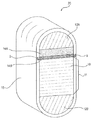
도 2a 내지 도 2c는 본 개시내용의 실시예들에 따른, 예시적인 전기화학 전지 스택 압축 시스템들(20)을 도시한다. 각각의 개별 전지(10)는 전기화학 전지 스택(11)을 형성하기 위해 압축 시스템(20) 내에 적층될 수 있다. 스택(11)은 임의의 적당한 수의 전지들(10)로 구성될 수 있다. 스택(11)은 스택(11)의 각각의 단부에 위치될 수 있는 단부 블록들(12A 및 12B) 사이에 위치될 수 있다. 단부 블록들(12A, 12B)은 충분한 내압 강도를 가진 임의의 적합한 금속, 플라스틱, 또는 세라믹 재료로 형성될 수 있고, 예를 들면, 알루미늄, 스틸, 스테인리스 스틸, 주철, 티타늄, 폴리 염화 비닐, 폴리 에틸렌, 폴리 프로필렌, 나일론, 폴리 에테르 에테르 케톤, 알루미나, 또는 임의의 그 조합이다. 2A-2C illustrate exemplary electrochemical cell
스택(11) 및 단부 블록들(12A, 12B)은 구조(15)에 수용될 수 있다. 권선 섬유 구조(15)는 전기화학 전지 시스템의 중량 및 크기를 그다지 증가시키지 않고 고압 전기화학 전지 스택을 수용할 수 있는 탄성 프레임을 제공할 수 있다. 구조(15)는 스택(11) 및 단부 블록들(12A, 12B)이 위치되는 규정된 형상을 가진 프레임을 형성할 수 있다. 도 2a는 긴 원형 구조(15)를 도시하지만, 구조(15)는, 예를 들면 직사각형, 타원형, 원형, 또는 정사각형을 포함한 임의의 적합한 형상일 수 있다. 구조(15)의 벽들은 스택(11) 및 단부 블록들(12A, 12B)과 구조(15)의 주변부를 따라 연속 경계부를 형성할 수 있고, 스택(11) 및 단부 블록들(12A, 12B)의 전방 및/또는 후방 부분들을 둘러쌀 수 있거나 둘러싸지 않을 수 있다. 단부 블록들(12A, 12B), 스택(11), 및 구조(15)에 수용되는 임의의 다른 부품들은 개구면(open face) 상에서 구조(15)의 벽들과 같은 높이로 놓이도록 구성될 수 있거나, 또는 부품들은 구조(15) 내로 오목해질 수 있거나, 이들은 구조(15)로부터 돌출될 수 있거나, 또는 임의의 적합한 조합으로 될 수 있다. The
구조(15)는 임의의 적당한 수의 전지화학 전지들(10)을 포함할 수 있는 스택(11) 및 단부 블록들(12A, 12B)을 수용하도록 치수화될 수 있다. 일부 실시예들에서, 구조(15)의 크기, 예를 들면 높이 H, 길이 L(도 2c에 도시된), 및/또는 폭은 변할 수 있고, 예를 들면, 구조(15)는 하기에 더 기술되는 바와 같이, 프리-로딩 동안 확장하도록 구성될 수 있다. 구조(15)는 원하는 내용물들, 예를 들면, 전기화학 스택(11) 및 단부 블록들(12A, 12B)을 꼭 끼워맞추도록, 전체 전기화학 전지 시스템의 크기를 실질적으로 증가시키지 않도록 치수화될 수 있다. The
일부 실시예들에서, 구조(15)는 확장 및 수축할 수 있는 권선 섬유들로 이루어질 수 있다. 예를 들면, 구조(15)는, 예를 들면 탄소, 유리, 또는 아라미드(예를 들면, KEVLAR®) 섬유들과 같은 권선 섬유들로 이루어질 수 있다. 섬유들은 단락 스택(1)의 가능성을 감소시키기 위해 비도전형이 될 수 있다. 일부 실시예들에서, 구조(15)는, 예를 들면 스틸, 스테인리스 스틸, 또는 알루미늄과 같은 금속 섬유들, 또는 인코넬과 같은 합금들로 이루어질 수 있다. 구조(15)는 단일 섬유들 또는 상이한 섬유들의 혼합으로 이루어질 수 있다. 또한, 구조(15)는 섬유들을 함께 결합하기 위해 에폭시 매트릭스 또는 다른 적당한 재료를 이용하여 또는 이용하지 않고 형성될 수 있다. 도 2c에 도시된 바와 같이, 구조(15)의 벽들은 두께 't'를 가질 수 있다. 예를 들면, 인장 강도와 같은 권선 섬유 재료 특성들 및 벽 두께 t는 스택(11)에 대한 원하는 압축력을 달성하기 위해 선택될 수 있다. 구조(15)를 구성하는 섬유들은 스택(11) 및 다양한 다른 부품들이 꼭 맞는 하나의 일체형 프레임 유닛을 형성하기 위해 함께 권선될 수 있다.In some embodiments, the
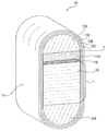
일부 실시예들에서, 도 2b에 도시된 것과 같이, 구조(15)는 다중층들(13A, 13B, 및 13C)로 이루어질 수 있다. 도 2b가 3개 층들을 도시하지만, 구조(15)의 다중-적층 실시예들은 임의의 적당한 수의 층들을 포함할 수 있다. 각 층은 단일 섬유들 또는 상이한 섬유들의 조합으로 이루어질 수 있다. 층들은 예를 들면 결합 또는 고정 메커니즘들을 통해 서로 부착될 수 있거나, 또는 예를 들면 마찰을 통해 부착되지 않고 함께 지탱될 수 있다. 또한, 일부 층들은 부착될 수 있지만 다른 층들은 부착되지 않을 수 있다. 다중-층 실시예들에서, 구조(15)는 층들 사이에 하나 이상의 슬립-면들(4)을 포함할 수 있다. 슬립-면(4)은 분리된 층으로 이루어질 수 있거나, 또는 예를 들면 폴리 테트라 플루오로 에틸렌(예를 들면, TEFLON®), 폴리 에테르 에테르 케톤, 폴리이미드, 나일론, 폴리 에틸렌, 또는 고분자층 또는 코팅, 또는 층들 사이의 마찰을 감소시키기 위한 임의의 다른 적합한 마찰-감소 재료와 같이, 층들 중 하나 상의 코팅으로 이루어질 수 있다. 통합된다면, 슬립-면(4)은 각각의 층 사이에 포함될 수 있거나, 모든 층들보다 소수의 층들 사이에 포함될 수 있다. 슬립-면(4)의 포함은 더 두꺼운 구조 벽들을 가진 실시예들에서 특히, 구조(15) 및 압축 시스템(20) 내의 응력의 양을 감소시킬 수 있다. In some embodiments, as shown in FIG. 2B, the
일부 실시예들에서, 단부 블록들(12A, 12B)은 또한, 단부 블록들(12A, 12B) 중 하나 또는 둘 다가 구조(15) 내에서 이동할 수 있도록 구조(15)에 꼭 맞게 구성될 수 있다. 예를 들면, 단부 블록들(12A, 12B)은 구조(15)의 벽들을 따라 미끄러지도록 허용될 수 있다. 이러한 구성은 구조(15)에서의 응력을 감소시킬 수 있고, 이것은 구조(15)가 더 얇은 벽들을 통합하도록 허용할 수 있다. 이러한 실시예들에서, 단부 블록들(12A, 12B)은, 예를 들면 폴리 테트라 플루오로 에틸렌(예를 들면, TEFLON®), 폴리 에테르 에테르 케톤, 폴리이미드, 나일론, 폴리 에틸렌과 같은, 적합한 마찰 감소 재료 또는 코팅을 포함할 수 있다. 다른 실시예들에서, 단부 블록들(12A, 12B)은 구조(15)의 벽들에 부착될 수 있거나, 또는 그렇지 않으면 단부 블록들(12A, 12B)이 일단 구조(15)에 삽입되면 미끄러지지 않도록 구성될 수 있다. In some embodiments, the end blocks 12A, 12B may also be configured to fit into the
본 개시내용의 또 다른 양태에 따라, 압축 시스템(20)은 구조(15) 내의 전기화학 스택(11)의 균일한 압축을 촉진하기 위해 하나 이상의 지브들을 포함할 수 있다. 지브들이 2개의 평행면들에 수직인 방향으로 함께 웨징되기 때문에, 지브들은 구조(15)에서 2개의 평행면들을 떨어지게 구동하기 위한 웨지로 작동할 수 있다. 예를 들면, 도 2a 내지 도 2c에 도시된 바와 같이, 지브들(14A, 14B)은 그들의 평행 배향을 유지하면서 스택(11)과 단부 블록(12A)을 떨어지게 구동하기 위해 전기화학 전지 스택(11)과 단부 블록(12A) 사이에 삽입될 수 있다. 지브(14B)는 평면 및 대향하는 각면(angled surface)을 가질 수 있다. 지브(14B)는 평면이 스택(11)에 인접하게 놓이고 각면이 상향으로 마주보게 하여 구조(15)에 삽입될 수 있다. 지브(14B)는 상향으로 마주보는 각면이 로딩되는 구조(15)의 전면을 향해 하향 방향으로 기울어지도록 배향될 수 있다. 지브(14A)는 그 후에 지브(14B) 옆에 삽입될 수 있고, 2개의 지브들은 함께 구동될 수 있다. 지브(14A)는 또한 평면 및 지브(14B)의 기울어진 면에 여각으로 기울어지는 대향하는 각면을 가질 수 있다. 지브(14A)의 각면은 각면이 또한 구조(15)의 전면을 향해 하향 방향으로 기울어지도록 지브(14B)의 각면에 인접하게 삽입될 수 있다. 따라서, 지브(14A)가 구조(15)에 삽입되고 14B에 대해 구동되기 때문에, 여각 기울기들은 서로에 대해 슬라이딩할 수 있어서, 지브들(14A, 14B)의 평면들을 밀면 서로 더 떨어지고 단부 블록(12A) 및 스택(11)을 향한다. 지브(14A)는 원하는 압축력이 스택(11)에 가해질 때까지 구조(15)에 삽입될 수 있다. In accordance with another aspect of the present disclosure, the
지브(14B)는 또한 구조(15)로부터 지브들(14A, 14B)의 삽입 및 제거에 도움을 주도록 구성되는 그립부(grip portion)를 포함할 수 있다. 일부 실시예들에서, 지브(14B)는 지브(14A)가 삽입될 때 지브(14B)의 이동을 감소시키기 위해 구조(15)의 벽들을 연동하도록 구성되는 하나 이상의 그립 메커니즘을 포함할 수 있다. 지브(14B)의 그립 메커니즘들은 구조(15)의 내면을 연동할 수 있고 지브(14B)로부터 연장하여 구조(15)의 에지 및/또는 외면을 연동할 수 있다. 예를 들면, 도 2a는 지브(14B)로부터 바깥쪽으로 돌출하고 구조(15)의 외면들의 에지들을 연동하는 후크부들(9)을 도시한다. 후크부들(9)은 지브(14A)가 삽입될 때, 지브(14B)가 구조(15)로 더 슬라이딩하는 것을 방지할 수 있다. 지브(14A)가 지브(14B)에 대해 웨징될 때 지브(14B)는 이동을 감소시키기 위해 예를 들면 못들(pegs) 또는 후크들 또는 텍스처면들(textured surfaces)과 같이, 임의의 적합한 그립 메커니즘 또는 그립 메커니즘들의 조합을 포함할 수 있다. 그립 메커니즘들은 임의의 적합한 크기, 형상, 및 배향일 수 있다. 일부 실시예들에서, 지브(14A)가 구동될 때 지브(14B)의 두꺼운 단부는 고정면에 대해 속박될 수 있어, 전지 스택(11)에 대한 변형을 방지한다. The jib 14B may also include a grip portion configured to assist in insertion and removal of the
2개의 지브들(14A, 14B)이 도시되었지만, 임의의 적합한 수의 지브들이 압축 시스템(20)에 포함될 수 있다. 또한, 지브들(14A, 14B)은 임의의 적합한 위치에 포함될 수 있고, 예를 들면, 지브들(14A, 14B)은 스택(11)과 단부 블록(12B) 사이에 위치될 수 있거나, 또는 지브들의 세트들이 스택(11)의 양측 상에 위치될 수 있다. Although two
지브들(14A, 14B)은 예를 들면, 스틸, 스테인리스 스틸, 세라믹, 또는 알루미늄과 같은 임의의 적합한 재료로 이루어질 수 있다. 지브들(14A, 14B)은 또한 압축 시스템(20)으로의 삽입을 용이하게 하거나 쓸림(galling)을 감소시키기 위해, 윤활류와 같은 임의의 적합한 코팅을 가질 수 있다. 이러한 적합한 마찰 감소 재료는 예를 들면, 폴리 테트라 플루오로 에틸렌(예를 들면, TEFLON®), 폴리 에테르 에테르 케톤, 폴리이미드, 나일론, 폴리 에틸렌, 또는 윤활성이 있는 고분자 코팅들, 또는 임의의 다른 적합한 재료를 포함할 수 있다.The
지브들(14A, 14B)은 구조(15)로의 삽입을 위한 임의의 적합한 형상 및 크기일 수 있다. 예를 들면, 일부 실시예들에서, 지브들(14A, 14B)의 크기 및 형상은 구조(15)의 내부 영역의 크기 및 형상을 적어도 부분적으로 반영할 수 있다. 지브들(14A, 14B)은 임의의 적합한 각으로 설계될 수 있다. 지브들(14A, 14B)이 설계되는 각은 스택(11)의 요구된 프리-로드에 적어도 부분적으로 기초할 수 있으며, 요구된 프리-로드는 스택(11)의 응용 및 수반하는 출력 요건들에 기초할 수 있다. 지브들(14A, 14B)의 크기 및 형상은 또한 구조(15)의 크기 대비 스택(11)의 크기에 부분적으로 기초할 수 있다. 예를 들면, 동일 크기의 구조(15)는 상이한 크기들의 스택들(11)을 수용하기 위해 이용될 수 있다. 따라서, 더 큰 지브들(14A, 14B)은 적절한 압축력을 인가하기 위해 더 작은 스택들(11)과 함께 이용될 수 있고, 그 반대로도 가능하다. The
지브들(14A, 14B)은 스택(11)에 압축을 인가하고, 균일한 부하를 유지하고, 시스템(20)을 안정화하고, 평탄성(planarity)을 제공하기 위해 이용될 수 있다. 조립 동안, 스택(11) 및 단부 블록들(12A, 12B)과 같은 압축 시스템(20)의 부품들이 구조(15)에 삽입될 수 있다. 이때, 구조(5)는 전기화학 전지들(10) 사이의 접촉을 유지하기 위해 스택(11)에 미리 결정된 압축력을 인가하도록 "프리-로드(pre-loaded)" 또는 사전-확장(pre-stretched)될 수 있다. 이것은 지브들(14A, 14B)과 같은 압축 메커니즘들을 이용하여 달성될 수 있다. 일단 다른 부품들이 삽입되면, 지브들(14A, 14B)은 임의의 갭들을 채우기 위해 구조(15)에 삽입될 수 있다. 지브들(14A, 14B)은 그들의 평행면들이 구조(15) 내의 주변 부품들, 예를 들면 스택(11) 상에서 원하는 압축 부하를 달성하기에 충분히 멀리 강제로 떨어지게 될 때까지 서로에 대해 웨징될 수 있다. 지브들(14A, 14B)이 프리로딩 동안 함께 구동되기 때문에, 권선 섬유 구조(15)의 벽들 내의 인장이 증가할 수 있고, 섬유들은 확장할 수 있다. 이것은 구조(15)의 높이 H를 증가시킬 수 있다. 구조(15)의 팽창량은 벽 두께 t 및 구조(15)를 구성하는 섬유들의 타입들에 적어도 부분적으로 의존할 수 있다. 프리-로딩 동안 구조(15)의 높이 H의 변화를 측정하는 것은 스택(11)에 인가되는 압축력을 나타낼 수 있고 프리-로딩 조건들의 더욱 정밀한 제어를 허용할 수 있다. 따라서 권선 섬유 구조(15)가 개시된 압축 메커니즘들과 함께 이용될 때, 시스템(20)은 스택(11)에 정확하게 및 효과적으로 압축 부하를 인가하기 위한 경량의, 저비용 시스템을 제공할 수 있다.The
동작 동안, 스택의 기체 압력이 증가함에 따라, 스택(11)에 대한 압축 부하는 전지들(10)이 분리될 때까지 감소될 수 있다. 이때, 구조(15)는 프리-로딩된 값보다 많이 확장하기 시작할 수 있다. 따라서, 스택(11)이 동작 동안 구조(15)보다 더 많이 가열되는 경우, 구조(15)는 차동 열 팽창으로 인해 프리-로딩된 값보다 많이 강제로 확장하게 될 수 있고 스택에 인가된 힘은 증가할 것이다. 따라서 구조(15)의 재료들 및 임의의 압축 메커니즘들은 동작 동안 압축력의 손실에 대한 잠재력을 감소시키기 위해 그들의 열 특성들에 기초하여 선택될 수 있다. During operation, as the gas pressure in the stack increases, the compressive load on the
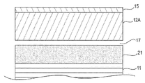
일부 실시예들에서, 시스템(20)은 지브들(14A, 14B) 대신에, 또는 이에 더 하여 다른 압축 메커니즘들을 포함할 수 있다. 예를 들면, 도 3a 및 도 3b에 도시된 바와 같이, 일부 실시예들에서, 하나 이상의 열 팽창 블록들(21)은 압축을 스택(11)에 인가하기 위해 이용될 수 있다. 블록(21)은 스택(11)의 온도보다 아래의 온도로 냉각될 수 있다. 프리-로딩 동안, 냉각된 블록(21)은 압축 시스템(20)에 삽입될 수 있다. 블록(21)의 온도가 구조(15)의 내부에서 증가함에 따라, 블록(21)은 팽창할 수 있고, 따라서 스택(11)에 압축을 인가할 수 있다. 블록(21)은 예를 들면, 적합한 금속들, 금속 합금들, 또는 세라믹들과 같은 적합한 열 팽창 특성들을 가진 임의의 재료 또는 재료들의 조합으로 이루어질 수 있다. 일부 실시예들에서, 블록(21)은 구조(15)의 열 팽창 계수보다 높은 열 팽창 계수를 가진 재료들로 이루어질 수 있다. 이러한 실시예들에서, 스택(11) 및 블록(21)이 동작 온도(일반적으로 30 내지 100℃)까지 올려짐에 따라, 블록(21)은 구조(15)보다 더 많이 팽창할 수 있다. 이러한 팽창은 스택(11)의 압축 부하를 유발할 수 있다. In some embodiments, the
열 활성화된 압축 메커니즘들의 하나의 이점은 블록(21)이 구조(15)에 삽입하기가 더 용이할 수 있다는 점이다. 열 팽창 전에 블록(21)을 삽입하는 것은 압축 시스템(20)의 주위의 부품들에 대한 마모 및 응력을 감소시킨다. 예를 들면, 도 3a에 도시된 바와 같이, 블록(21)이 프리-로딩 동안 처음 삽입될 때, 압축 시스템(20)에는 갭(17)이 존재할 수 있다. 블록(21)이 따뜻해짐에 따라, 블록(21)이 팽창하고 주위 공간을 채울 때 갭(17)이 사라질 수 있다(도 3b에 도시). 일단 갭(17)이 사라지면, 블록(21)의 연속 팽창은 스택(11)을 압축하고 압축 부하를 인가하기 시작할 수 있다. 블록(21)의 열 특성들은 구조(15)에서 스택(11)의 크기 및 갭(17)의 크기에 기초하여 원하는 압축 부하를 부여하기 위해 선택될 수 있다. 갭(17)이 삽입된 블록(21)과 단부 블록(12A) 사이에서 보일 때, 블록(21)은 갭(17)이 블록(21)의 어느 한 측면 상에 또는 블록(21)의 양 측면들 상에서 발생하도록 배향될 수 있음을 이해할 것이다. 또한, 갭(17)은 구조(15) 내의 임의의 영역에서 발생할 수 있다. One advantage of the thermally activated compression mechanisms is that the
블록(21)이 본 명세서에서 팽창 부재로서 기술되지만, 블록(21) 대신에, 또는 이에 부가하여 하나 이상의 단부 블록들(12A 또는 12B)이 열 압축을 제공하도록 설계될 수 있다. 또한, 지브들(14A, 14B) 역시 웨지로서의 이용을 통해 뿐만 아니라 열 팽창을 통해 압축을 인가하도록 허용하기 위해 적절한 재료로 이루어질 수 있다. 또한, 다수의 열 팽창 블록들(21)이 이용될 수 있거나, 또는 열 팽창 블록(21) 및 지브들(14A, 14B)의 조합이 구조(15)에 삽입될 수 있다.Although
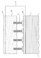
본 개시내용의 다른 실시예들은 또 다른 압축 메커니즘들을 포함할 수 있다. 도 4에 도시된 바와 같이, 내부 구동 나사들을 구비한 나사 압축 유닛(19)은 압축 부하를 인가하기 위해 이용될 수 있다. 압축 유닛(19)은 구조(15)로부터 제거 가능하도록 구성될 수 있거나 구조(15)에 부착될 수 있다. 도 4에 도시된 바와 같이, 스레드형 나사들(18; threaded screws)은 압축 유닛(19)의 베이스(16B)로부터 연장할 수 있다. 나사들(18)의 대향 단부들은 압축 유닛(19)의 블록(16A)의 보안적인 스레드형 입구들(도시되지 않음)로 연장될 수 있다. 나사들(18)을 한 방향으로 회전시키는 것은 나사들(18)로 하여금 블록(16A)의 스레드형 입구들로 더 조여 들어가게 할 수 있어, 블록(16A)을 베이스(16B)에 더 가깝게 이동시키고 16A와 16B 사이의 갭을 감소시킨다. 16A와 16B 사이의 갭을 감소시키는 것은 스택(11)에 인가되는 압축력을 감소시킬 수 있다. 나사들(18)을 반대 방향으로 회전시키는 것은 나사들(18)로 하여금 블록(16A)의 스레드형 입구들로부터 풀려나오게 할 수 있어, 블록(16A)을 베이스(16B)로부터 떨어지게 이동시키고 16A와 16B 사이의 갭을 증가시킨다. 16A와 16B 사이의 갭을 증가시키는 것은 스택(11)에 인가되는 압축력을 증가시킬 수 있다. 프리-로딩 동안, 압축 유닛(19)은 블록(16A)과 베이스(16B) 사이에 갭이 없거나 거의 없을 때 구조(15)에 삽입될 수 있다. 일단 삽입되면, 나사들(18)은 스택(11)에 원하는 압축력을 인가하기 위해 블록(16A)과 베이스(16B) 사이의 갭을 증가시키도록 회전될 수 있다. Other embodiments of the present disclosure may include other compression mechanisms. As shown in Figure 4, a
4개의 나사들(18)이 도 4에 도시되었지만, 임의의 적합한 수의 스레드형 부품들이 압축 유닛(19)에 포함될 수 있다. 또한, 스레드형 부품들은 베이스(16B) 상에서 임의의 적합한 배열로 분포될 수 있다. 나사들(18)은 임의의 적합한 형상 또는 크기일 수 있고 임의의 적합한 재료, 예를 들면 임의의 금속, 금속 합금, 또는 세라믹으로 이루어질 수 있다. 임의 수의 압축 유닛들(19)은 시스템(20)에 통합될 수 있고, 압축 유닛들(19)은 지브들(14A, 14B) 및 열 팽창 블록(21) 중 어느 하나 또는 둘 다의 대신에 또는 이에 부가하여 이용될 수 있다. 또한, 일부 실시예들에서, 압축 유닛(19)은 또한 부품들 또는 이전에 기술된 압축 메커니즘들 중 하나에 통합될 수 있다. 예를 들면, 단부 블록들(12A, 12B), 지브들(14A, 14B), 또는 블록(21) 중 하나 이상은 내부 구동 나사들을 포함할 수 있다. Although four
개시된 압축 시스템(20)의 일부 실시예들의 하나의 부가적 이점(전체 스택 크기 및 중량의 감소 외에)은 압축 시스템(20)이 상이한 크기들의 전기화학 스택들을 수용할 수 있다는 점이다. 지브들(14A, 14B), 열 팽창 블록(21), 및/또는 압축 유닛(19)을 통합함으로써, 구조(15)는 상이한 응용들 및 출력 레벨들에 적합한 상이한 수들의 전기화학 전지들을 구비한 상이한 크기들의 전기화학 전지 스택들을 수용하도록 구성될 수 있다. 더 소수의 전기화학 전지들(10)을 구비한 더 작은 스택(11)이 구조(15) 내에 포함되는 경우, 더 큰 압축 메커니즘들 또는 압축 메커니즘들의 더 큰 수 또는 조합이 임의의 부가 공간을 채우고 원하는 압축력을 인가하기 위해 프리-로딩 동안 스택(11) 주위에 삽입될 수 있다. 대안적으로, 더 많은 전지들(10)을 구비한 더 큰 전기화학 전지 스택(11)이 구조(15)에 수용되는 경우, 더 작은 압축 메커니즘들 또는 더 소수의 압축 메커니즘들이 스택(11) 주위에 삽입될 수 있다. 따라서, 동일한 기본 구조(15)가 상이한 응용들 및 상이한 출력 레벨들에 적절한 상이한 크기의 전기화학 전지 스택들을 수용할 수 있다. 이것은 다양한 응용들에 적합한 다양한 전기화학 전지 스택 크기들을 수용하기 위한 하나의 표준 구조(15)가 생성될 수 있기 때문에, 제조 비용들을 절감할 수 있다. 따라서, 동일한 기본 기술은 다양한 전지 수들 및 크기들의 스택들에 대한 구조들을 생성할 수 있다. 상이한 수들 또는 상이한 타입들의 상술된 압축 메커니즘들을 통합함으로써, 동일한 구조(15)는 연장된 시간 기간에 걸쳐 동작 조건들의 범위를 맞출 수 있다(accommodate). One additional advantage of some embodiments of the disclosed compression system 20 (besides reduction of the overall stack size and weight) is that the
또한, 구조(15)의 벽 두께 및 구조(15)를 형성하기 위해 선택되는 섬유들의 타입들은 구조(15)가 전기화학 전지 스택 크기들의 범위를 맞추도록 허용할 수 있다. 또한, 구조(15)의 다층 실시예들에서, 구조(15)는 하나 이상의 층들이 다른 층들로부터 제거 가능하거나 분리 가능하도록 구성될 수 있다. 예를 들면 하나 이상의 층들은 다른 층 내에 끼워 넣어질 수 있고(nest), 주위층으로부터 완전하게 제거될 수 있다. 도 2b에 도시된 것과 같은 실시예에서, 층(13A)은 층(13B) 내에 끼워넣어질 수 있거나 이로부터 제거될 수 있고, 예를 들면 슬립-면(4)이 제거를 용이하게 할 수 있다. 구조(15)에 삽입될 전기화학 전지 스택(11)의 크기에 의존하여, 구조(15)를 현재 응용 가능한 동작 조건들에 적응시키기 위해 하나 이상의 층들이 제거될 수 있다. In addition, the wall thickness of
상술된 실시예들의 응용은 고압 조건들 하에서 동작하는 전기화학 전지들을 포함하는 전지화학 전지들의 성능을 개선할 수 있다. The application of the above-described embodiments can improve the performance of battery chemistry cells comprising electrochemical cells operating under high pressure conditions.
본 개시내용의 많은 특징들 및 이점들은 상세한 명세로부터 명백하고, 따라서 첨부된 청구항들에 의해, 본 개시내용의 참된 사상 및 범위 내에 있는 본 개시내용의 모든 이러한 특징들 및 이점들을 커버하도록 의도된다. 또한, 많은 수정들 및 변형들이 본 기술분야의 통상의 기술자들에게 쉽게 발생할 것이므로, 본 개시내용을 예시되고 기술된 정확한 구성 및 동작으로 제한하는 것은 바람직하지 않고, 따라서 모든 적절한 수정들 및 등가물들은 본 개시내용의 범위 내에 있는 것에 의존될 수 있다.Many features and advantages of the disclosure are apparent from the detailed specification and, therefore, are intended to cover all such features and advantages of the disclosure, which fall within the true spirit and scope of the disclosure, by the appended claims. In addition, since many modifications and variations will readily occur to those skilled in the art, it is not desired to limit the present disclosure to the exact construction and operation as illustrated and described, and accordingly, all suitable modifications and equivalents may be resorted to But may be dependent on what is within the scope of the disclosure.
또한, 본 기술분야의 통상의 기술자들은 본 개시내용이 기초로 하는 개념이 본 개시내용의 여러 목적들을 수행하기 위한 다른 구조들, 방법들, 및 시스템들을 설계하기 위한 기초로서 쉽게 이용될 수 있음을 알 것이다. 따라서, 청구항들은 이전의 기술에 의해 제한되는 것으로서 간주되어서는 안 된다.In addition, those of ordinary skill in the art will readily appreciate that the concepts underlying the present disclosure can readily be used as a basis for designing other structures, methods, and systems for performing the various purposes of the present disclosure I will know. Accordingly, the claims should not be construed as being limited by the prior art.
Claims (28)
스택 구성에서 축을 따라 배열되는 복수의 전기화학 전지들을 포함하도록 구성된 일체형, 중공 프레임(integral, hollow frame)을 포함하고, 상기 프레임은 규정된 형상을 가지고 삽입시 상기 전기화학 전지 스택의 주변부 주위에 연속 경계부(continuous border)를 형성하고, 상기 프레임은 복수의 섬유들로 이루어지는, 전기화학 전지 스택 압축 시스템.An electrochemical cell stack compression system comprising:
An integrated, hollow frame configured to include a plurality of electrochemical cells arranged along an axis in a stack configuration, said frame having a defined shape and being continuous about the periphery of the electrochemical cell stack upon insertion Wherein the frame forms a continuous border, the frame comprising a plurality of fibers.
상기 프레임은 상이한 재료들로 구성된 복수의 섬유들로 이루어지는, 전기화학 전지 스택 압축 시스템.The method according to claim 1,
Wherein the frame comprises a plurality of fibers comprised of different materials.
상기 프레임은 섬유들로 이루어진 다중층들을 포함하는, 전기화학 전지 스택 압축 시스템.The method according to claim 1,
Wherein the frame comprises multiple layers of fibers.
상기 프레임은 섬유들로 이루어진 상기 다중층들 중 적어도 하나 사이에 위치된 마찰-감소층(friction-reducing layer)을 포함하는, 전기화학 전지 스택 압축 시스템.The method of claim 3,
Wherein the frame comprises a friction-reducing layer located between at least one of the multiple layers of fibers.
상기 프레임은 적어도 2개의 대향하는 벽면들을 포함하는, 전기화학 전지 스택 압축 시스템.The method according to claim 1,
Wherein the frame comprises at least two opposed wall surfaces.
상기 프레임은 또한 상기 프레임의 단부 영역에 위치되는 적어도 하나의 단부 블록을 포함하도록 구성되는, 전기화학 전지 스택 압축 시스템.The method according to claim 1,
Wherein the frame is also configured to include at least one end block located in an end region of the frame.
상기 프레임은 또한 상기 전기화학 전지 스택에 압축력(compressive force)을 인가하도록 구성되는 적어도 하나의 압축 메커니즘을 포함하도록 구성되는, 전기화학 전지 스택 압축 시스템.The method according to claim 1,
Wherein the frame is also configured to include at least one compression mechanism configured to apply a compressive force to the electrochemical cell stack.
상기 압축 메커니즘은 적어도 하나의 지브(gib)를 포함하는, 전기화학 전지 스택 압축 시스템.8. The method of claim 7,
Wherein the compression mechanism comprises at least one gib.
상기 압축 메커니즘은 가열시 팽창하도록 구성되는, 전기화학 전지 스택 압축 시스템.8. The method of claim 7,
Wherein the compression mechanism is configured to expand upon heating.
상기 압축 메커니즘은 2개의 분리된 부분들 사이에서 연장하는 하나 이상의 내부 구동 나사들(internal drive screws)을 포함하고, 상기 내부 구동 나사들을 한 방향으로 회전시키는 것은 상기 2개의 부분들을 서로 더 떨어지게 이동시키고, 상기 내부 구동 나사들을 반대 방향으로 회전시키는 것은 상기 2개의 부분들을 서로 더 가깝게 이동시키는, 전기화학 전지 스택 압축 시스템.8. The method of claim 7,
The compression mechanism includes one or more internal drive screws extending between two separate portions, wherein rotating the internal drive screws in one direction moves the two portions further apart And rotating the internal drive screws in opposite directions moves the two parts closer together.
상기 프레임은 다수의 상이한 크기들의 전기화학 전지 스택들을 수용하도록 구성되는, 전기화학 전지 스택 압축 시스템.The method according to claim 1,
Wherein the frame is configured to accommodate a plurality of different sized electrochemical cell stacks.
규정된 형상을 가진 구조로서,
전기화학 스택을 형성하기 위해 축을 따라 직렬로 배열되는 복수의 전기화학 전지들; 및
상기 전기화학 스택의 상기 축에 인접하게 및 상기 축을 따라 위치되는 상기 전기화학 스택에 압축력을 인가하도록 구성된 적어도 하나의 압축 메커니즘을 수용 및 포함하도록 구성되는 상기 규정된 형상을 가진 구조를 포함하고;
상기 구조는 포함시 상기 전기화학 스택을 둘러싸고, 상기 적어도 하나의 압축 메커니즘이 포함될 때 이를 둘러싸는 연속 경계부를 형성하는, 전기화학 스택 압축 시스템.An electrochemical stack compression system comprising:
As a structure having a prescribed shape,
A plurality of electrochemical cells arranged in series along an axis to form an electrochemical stack; And
A structure having the prescribed shape configured to receive and include at least one compression mechanism configured to apply a compressive force to the electrochemical stack located adjacent to and along the axis of the electrochemical stack;
Wherein the structure surrounds the electrochemical stack when included and forms a continuous boundary surrounding the electrochemical stack when the at least one compression mechanism is included.
상기 압축 메커니즘은 적어도 하나의 지브를 포함하는, 전기화학 스택 압축 시스템.13. The method of claim 12,
Wherein the compression mechanism comprises at least one jib.
상기 압축 메커니즘은 온도의 증가에 응답하여 팽창하도록 구성되는 블록을 포함하는, 전기화학 스택 압축 시스템.13. The method of claim 12,
Wherein the compression mechanism comprises a block configured to expand in response to an increase in temperature.
상기 압축 메커니즘은, 내부 구동 나사들이 제 1 방향으로 회전될 때 상기 압축 메커니즘의 크기를 증가시키고 상기 내부 구동 나사들이 상기 제 1 방향과 반대인 제 2 방향으로 회전될 때 상기 압축 메커니즘의 크기를 감소시키도록 구성되는 상기 내부 구동 나사들을 포함하는, 전기화학 스택 압축 시스템.13. The method of claim 12,
Wherein the compression mechanism increases the size of the compression mechanism when the internal drive screws are rotated in a first direction and decreases the size of the compression mechanism as the internal drive screws are rotated in a second direction opposite the first direction Said internal drive screws being configured to cause said internal drive screw to rotate.
상기 구조는 감겨진 섬유들(wound fibers)로 이루어지는, 전기화학 스택 압축 시스템.13. The method of claim 12,
Wherein the structure consists of wound fibers.
상기 섬유들은 비-도전성인, 전기화학 스택 압축 시스템.13. The method of claim 12,
Wherein the fibers are non-conductive.
상기 섬유들은 탄소인, 전기화학 스택 압축 시스템.13. The method of claim 12,
Wherein the fibers are carbon.
상기 전기화학 스택의 상기 축을 따른 상기 구조의 높이는 상기 압축 메커니즘을 수용할 때 상기 압축 메커니즘에 의해 상기 전기화학 스택에 인가되는 부하에 응답하여 변하는, 전기화학 스택 압축 시스템.13. The method of claim 12,
Wherein the height of the structure along the axis of the electrochemical stack changes in response to a load applied to the electrochemical stack by the compression mechanism when the compression mechanism is accommodated.
상기 전기화학 스택을 상기 구조에 삽입하는 단계;
상기 적어도 하나의 압축 메커니즘을 상기 구조에 삽입하는 단계;
상기 압축 시스템 내에 미리 결정된 부하를 인가하도록 상기 압축 메커니즘을 구성하는 단계; 및
상기 압축 메커니즘에 의해 인가되는 상기 부하를 결정하기 위해 상기 전기화학 스택의 상기 축을 따른 상기 구조의 높이의 변화를 측정하는 단계를 포함하는, 프리-로딩 방법.A method for pre-loading the compression system of claim 12, the method comprising:
Inserting the electrochemical stack into the structure;
Inserting the at least one compression mechanism into the structure;
Configuring the compression mechanism to apply a predetermined load within the compression system; And
And measuring a change in height of the structure along the axis of the electrochemical stack to determine the load applied by the compression mechanism.
적어도 하나의 단부 블록을 상기 구조에 삽입하는 단계를 더 포함하는, 프리-로딩 방법.21. The method of claim 20,
Further comprising inserting at least one end block into the structure.
상기 압축 메커니즘은 2개의 지브들을 포함하고, 상기 압축 메커니즘 구성 단계는 상기 2개의 지브들을 서로에 대해 웨징(wedging)하는 단계를 포함하는, 프리-로딩 방법.21. The method of claim 20,
Wherein the compression mechanism comprises two jibs and the compressing mechanism configuration step comprises wedging the two jibs with respect to each other.
상기 압축 메커니즘 구성 단계는 상기 압축 메커니즘을 팽창시키기 위해 상기 압축 시스템의 온도를 증가시키는 단계를 포함하는, 프리-로딩 방법.21. The method of claim 20,
Wherein the step of configuring the compression mechanism comprises increasing the temperature of the compression system to expand the compression mechanism.
상기 압축 메커니즘 구성 단계는 상기 압축 메커니즘을 팽창시키기 위해 복수의 내부 구동 나사들을 회전시키는 단계를 포함하는, 프리-로딩 방법.21. The method of claim 20,
Wherein the step of configuring the compression mechanism comprises rotating a plurality of internal drive screws to inflate the compression mechanism.
규정된 형상을 가지고 복수의 감겨진 섬유들로 이루어진 일체형, 중공 구조;
전기화학 스택을 형성하기 위해 축을 따라 직렬로 배열되는 복수의 전기화학 전지들로서, 상기 전기화학 스택은 상기 구조 내에 포함되는, 상기 복수의 전기화학 전지들;
상기 구조 내에 포함되고 상기 구조의 단부 영역에 위치되는 적어도 하나의 단부 블록; 및
상기 구조 내에 포함되는 적어도 하나의 압축 메커니즘으로서, 상기 전기화학 스택에 압축력을 인가하도록 구성되는 상기 적어도 하나의 압축 메커니즘을 포함하고,
상기 전기화학 스택, 상기 적어도 하나의 단부 블록, 및 상기 적어도 하나의 압축 메커니즘은 상기 구조 내에 직렬로 포함되어, 상기 구조가 상기 전기화학 스택, 상기 적어도 하나의 단부 블록, 및 상기 적어도 하나의 압축 메커니즘의 주변부의 주위에 및 인접하게 연속 경계부를 형성하는, 전기화학 스택 압축 시스템.An electrochemical stack compression system comprising:
An integral, hollow structure of a plurality of wound fibers with a defined shape;
A plurality of electrochemical cells arranged in series along an axis to form an electrochemical stack, said electrochemical stack being comprised within said structure;
At least one end block contained within the structure and located in an end region of the structure; And
At least one compression mechanism included within the structure, the at least one compression mechanism being configured to apply a compressive force to the electrochemical stack,
Wherein said electrochemical stack, said at least one end block, and said at least one compression mechanism are contained in series within said structure, said structure comprising an electrochemical stack, said at least one end block, and said at least one compression mechanism Forming a continuous boundary around and adjacent the periphery of the electrochemical stack.
상기 섬유들은 상기 압축력의 변화들에 응답하여 확장 및 수축하도록 구성되는, 전기화학 스택 압축 시스템.26. The method of claim 25,
Wherein the fibers are configured to expand and contract in response to changes in the compressive force.
상기 적어도 하나의 압축 메커니즘은 지브를 포함하는, 전기화학 스택 압축 시스템.26. The method of claim 25,
Wherein the at least one compression mechanism comprises a jib.
상기 적어도 하나의 압축 메커니즘은 팽창하도록 구성되는, 전기화학 스택 압축 시스템.26. The method of claim 25,
Wherein the at least one compression mechanism is configured to expand.
Applications Claiming Priority (3)
| Application Number | Priority Date | Filing Date | Title |
|---|---|---|---|
| US201361775068P | 2013-03-08 | 2013-03-08 | |
| US61/775,068 | 2013-03-08 | ||
| PCT/US2014/017195 WO2014137601A2 (en) | 2013-03-08 | 2014-02-19 | Electrochemical stack compression system |
Publications (1)
| Publication Number | Publication Date |
|---|---|
| KR20150128826A true KR20150128826A (en) | 2015-11-18 |
Family
ID=50240005
Family Applications (1)
| Application Number | Title | Priority Date | Filing Date |
|---|---|---|---|
| KR1020157027579A KR20150128826A (en) | 2013-03-08 | 2014-02-19 | Electrochemical stack compression system |
Country Status (10)
| Country | Link |
|---|---|
| US (2) | US10109880B2 (en) |
| EP (2) | EP3557673B1 (en) |
| JP (2) | JP6609189B2 (en) |
| KR (1) | KR20150128826A (en) |
| CN (2) | CN105122528B (en) |
| AU (2) | AU2014226462B2 (en) |
| BR (1) | BR112015017429A2 (en) |
| CA (1) | CA2898226A1 (en) |
| ES (2) | ES2734527T3 (en) |
| WO (1) | WO2014137601A2 (en) |
Cited By (1)
| Publication number | Priority date | Publication date | Assignee | Title |
|---|---|---|---|---|
| KR20210092038A (en) * | 2020-01-15 | 2021-07-23 | 한국에너지기술연구원 | Fastening structure for cell stack of flow type energy storage device |
Families Citing this family (5)
| Publication number | Priority date | Publication date | Assignee | Title |
|---|---|---|---|---|
| JP6646427B2 (en) * | 2015-12-15 | 2020-02-14 | 豊田鉄工株式会社 | Battery case |
| GB2563848B (en) * | 2017-06-26 | 2022-01-12 | Ceres Ip Co Ltd | Fuel cell stack assembly |
| DE102017215510A1 (en) * | 2017-09-05 | 2019-03-07 | Volkswagen Ag | A method of determining the compressive tensile force acting on a fuel cell stack |
| KR20230002540A (en) | 2020-03-31 | 2023-01-05 | 플러그 파워 인코포레이티드 | Method and system for electrochemically compressing gaseous hydrogen |
| US11746427B2 (en) * | 2021-07-05 | 2023-09-05 | EvolOH, Inc. | Scalable electrolysis cell and stack and method of high-speed manufacturing the same |
Family Cites Families (24)
| Publication number | Priority date | Publication date | Assignee | Title |
|---|---|---|---|---|
| JPH06188023A (en) * | 1992-12-22 | 1994-07-08 | Fuji Electric Co Ltd | Flat plate-shaped solid electrolyte type fuel cell |
| JP3505010B2 (en) * | 1995-07-07 | 2004-03-08 | 本田技研工業株式会社 | Fuel cell and its fastening method |
| US5789091C1 (en) * | 1996-11-19 | 2001-02-27 | Ballard Power Systems | Electrochemical fuel cell stack with compression bands |
| JP2002063929A (en) * | 2000-08-14 | 2002-02-28 | Sony Corp | Stack structure of fuel cell |
| US6663996B2 (en) | 2000-12-22 | 2003-12-16 | Ballard Power Systems Inc. | Compression mechanism for an electrochemical fuel cell assembly |
| US20030072545A1 (en) * | 2001-10-12 | 2003-04-17 | Fujikura Ltd. | Drop cable and method of fabricating same |
| US6862801B2 (en) | 2001-11-30 | 2005-03-08 | Ballard Power Systems Inc. | Systems, apparatus and methods for isolating, compressing and/or retaining the structure of a fuel cell stack |
| AT5881U1 (en) * | 2002-05-13 | 2003-01-27 | Zeug Design G M B H | SKATING |
| JP2004327125A (en) * | 2003-04-22 | 2004-11-18 | Nissan Motor Co Ltd | External manifold type fuel cell |
| WO2005069419A1 (en) * | 2004-01-20 | 2005-07-28 | Hitachi, Ltd. | Fuel container for fuel cell |
| US20060093890A1 (en) * | 2004-10-29 | 2006-05-04 | Steinbroner Matthew P | Fuel cell stack compression systems, and fuel cell stacks and fuel cell systems incorporating the same |
| US7294427B2 (en) * | 2004-12-27 | 2007-11-13 | Fuelcell Energy, Inc. | Manifold gasket accommodating differential movement of fuel cell stack |
| FI20055017A (en) * | 2005-01-13 | 2006-07-14 | Waertsilae Finland Oy | Arrangement for pressing of fuel cells in a fuel cell stack |
| DE102006030605A1 (en) * | 2006-07-03 | 2008-01-10 | Webasto Ag | Arrangement with a fuel cell stack and method for clamping a fuel cell stack |
| EP1879251B1 (en) * | 2006-07-14 | 2012-06-06 | Topsøe Fuel Cell A/S | Compression assembly, solid oxide fuel cell stack, a process for compression of the solid oxide fuel cell stack and its use |
| JP4910707B2 (en) * | 2007-01-05 | 2012-04-04 | トヨタ自動車株式会社 | Fuel cell |
| RU2442247C2 (en) * | 2007-01-26 | 2012-02-10 | Топсеэ Фюэль Селл А/С | The construction for fixing the batteries fuel cells and the solid oxide fuel cells |
| US8007951B2 (en) * | 2007-06-08 | 2011-08-30 | GM Global Technology Operations LLC | Fuel cell compression retention system using compliant strapping |
| KR100986456B1 (en) * | 2008-03-04 | 2010-10-08 | 포항공과대학교 산학협력단 | Device for clamping fuel cell stack |
| ES2480272T3 (en) | 2009-03-13 | 2014-07-25 | Topsoe Fuel Cell A/S | Compression housing for a fuel cell stack and method for manufacturing a compression housing for a fuel cell stack |
| KR101106103B1 (en) * | 2009-04-01 | 2012-01-18 | 주식회사 엘지화학 | Battery Module of Improved Safety |
| US9331321B2 (en) * | 2011-03-31 | 2016-05-03 | GM Global Technology Operations LLC | Fabric composite support or enclosure for an automotive battery pack |
| EP2546915B1 (en) | 2011-07-11 | 2014-06-11 | Belenos Clean Power Holding AG | Housing assembly for a fuel cell stack |
| JP5684665B2 (en) * | 2011-07-13 | 2015-03-18 | 本田技研工業株式会社 | Fuel cell stack |
-
2014
- 2014-02-19 BR BR112015017429A patent/BR112015017429A2/en not_active Application Discontinuation
- 2014-02-19 EP EP19177224.3A patent/EP3557673B1/en active Active
- 2014-02-19 ES ES14709057T patent/ES2734527T3/en active Active
- 2014-02-19 CN CN201480012808.XA patent/CN105122528B/en active Active
- 2014-02-19 JP JP2015561380A patent/JP6609189B2/en active Active
- 2014-02-19 CN CN201910760568.6A patent/CN110429314A/en active Pending
- 2014-02-19 KR KR1020157027579A patent/KR20150128826A/en not_active Application Discontinuation
- 2014-02-19 CA CA2898226A patent/CA2898226A1/en not_active Abandoned
- 2014-02-19 WO PCT/US2014/017195 patent/WO2014137601A2/en active Application Filing
- 2014-02-19 ES ES19177224T patent/ES2837698T3/en active Active
- 2014-02-19 AU AU2014226462A patent/AU2014226462B2/en active Active
- 2014-02-19 EP EP14709057.5A patent/EP2965378B1/en active Active
- 2014-03-05 US US14/198,317 patent/US10109880B2/en active Active
-
2018
- 2018-06-20 AU AU2018204418A patent/AU2018204418A1/en not_active Abandoned
- 2018-09-18 US US16/133,804 patent/US20190020051A1/en not_active Abandoned
-
2019
- 2019-10-25 JP JP2019194139A patent/JP2020031062A/en not_active Ceased
Cited By (1)
| Publication number | Priority date | Publication date | Assignee | Title |
|---|---|---|---|---|
| KR20210092038A (en) * | 2020-01-15 | 2021-07-23 | 한국에너지기술연구원 | Fastening structure for cell stack of flow type energy storage device |
Also Published As
| Publication number | Publication date |
|---|---|
| EP3557673B1 (en) | 2020-11-25 |
| US10109880B2 (en) | 2018-10-23 |
| JP2016514351A (en) | 2016-05-19 |
| CN110429314A (en) | 2019-11-08 |
| JP6609189B2 (en) | 2019-11-20 |
| EP2965378B1 (en) | 2019-06-19 |
| US20190020051A1 (en) | 2019-01-17 |
| BR112015017429A2 (en) | 2017-07-11 |
| WO2014137601A3 (en) | 2014-11-06 |
| CA2898226A1 (en) | 2014-09-12 |
| CN105122528B (en) | 2019-09-10 |
| US20140255817A1 (en) | 2014-09-11 |
| WO2014137601A2 (en) | 2014-09-12 |
| EP3557673A1 (en) | 2019-10-23 |
| ES2837698T3 (en) | 2021-07-01 |
| EP2965378A2 (en) | 2016-01-13 |
| AU2014226462A1 (en) | 2015-10-08 |
| AU2014226462B2 (en) | 2018-03-29 |
| AU2018204418A1 (en) | 2018-07-12 |
| JP2020031062A (en) | 2020-02-27 |
| ES2734527T3 (en) | 2019-12-10 |
| CN105122528A (en) | 2015-12-02 |
Similar Documents
| Publication | Publication Date | Title |
|---|---|---|
| US20190020051A1 (en) | Electrochemical stack compression system | |
| JP6356127B2 (en) | Bipolar plate design for use in electrochemical cells | |
| US7125625B2 (en) | Electrochemical cell and bipolar assembly for an electrochemical cell | |
| US10468691B2 (en) | Bipolar plates for use in conduction-cooled electrochemical cells | |
| EP2904656B1 (en) | Resilient flow structures for electrochemical cell | |
| JP7460323B2 (en) | Fuel cell with modular base active area | |
| WO2006047015A2 (en) | Passive dual-phase cooling for fuel cell assemblies | |
| BARBIR | FUEL CELL STACK DESIGN PRINCIPLES WITHSOME DESIGN CONCEPTS OF MICRO-MINI FUEL CELLS |
Legal Events
| Date | Code | Title | Description |
|---|---|---|---|
| A201 | Request for examination | ||
| E902 | Notification of reason for refusal | ||
| E601 | Decision to refuse application |