KR20150097475A - Methods of forming images by laser micromachining - Google Patents
Methods of forming images by laser micromachining Download PDFInfo
- Publication number
- KR20150097475A KR20150097475A KR1020157013490A KR20157013490A KR20150097475A KR 20150097475 A KR20150097475 A KR 20150097475A KR 1020157013490 A KR1020157013490 A KR 1020157013490A KR 20157013490 A KR20157013490 A KR 20157013490A KR 20150097475 A KR20150097475 A KR 20150097475A
- Authority
- KR
- South Korea
- Prior art keywords
- laser
- parameter values
- concave
- range
- processing parameters
- Prior art date
Links
Images


Classifications
-
- B23K26/0066—
-
- B—PERFORMING OPERATIONS; TRANSPORTING
- B23—MACHINE TOOLS; METAL-WORKING NOT OTHERWISE PROVIDED FOR
- B23K—SOLDERING OR UNSOLDERING; WELDING; CLADDING OR PLATING BY SOLDERING OR WELDING; CUTTING BY APPLYING HEAT LOCALLY, e.g. FLAME CUTTING; WORKING BY LASER BEAM
- B23K26/00—Working by laser beam, e.g. welding, cutting or boring
- B23K26/0006—Working by laser beam, e.g. welding, cutting or boring taking account of the properties of the material involved
-
- B23K26/0018—
-
- B23K26/0075—
-
- B—PERFORMING OPERATIONS; TRANSPORTING
- B23—MACHINE TOOLS; METAL-WORKING NOT OTHERWISE PROVIDED FOR
- B23K—SOLDERING OR UNSOLDERING; WELDING; CLADDING OR PLATING BY SOLDERING OR WELDING; CUTTING BY APPLYING HEAT LOCALLY, e.g. FLAME CUTTING; WORKING BY LASER BEAM
- B23K26/00—Working by laser beam, e.g. welding, cutting or boring
- B23K26/352—Working by laser beam, e.g. welding, cutting or boring for surface treatment
-
- B—PERFORMING OPERATIONS; TRANSPORTING
- B23—MACHINE TOOLS; METAL-WORKING NOT OTHERWISE PROVIDED FOR
- B23K—SOLDERING OR UNSOLDERING; WELDING; CLADDING OR PLATING BY SOLDERING OR WELDING; CUTTING BY APPLYING HEAT LOCALLY, e.g. FLAME CUTTING; WORKING BY LASER BEAM
- B23K26/00—Working by laser beam, e.g. welding, cutting or boring
- B23K26/36—Removing material
- B23K26/361—Removing material for deburring or mechanical trimming
-
- B—PERFORMING OPERATIONS; TRANSPORTING
- B23—MACHINE TOOLS; METAL-WORKING NOT OTHERWISE PROVIDED FOR
- B23K—SOLDERING OR UNSOLDERING; WELDING; CLADDING OR PLATING BY SOLDERING OR WELDING; CUTTING BY APPLYING HEAT LOCALLY, e.g. FLAME CUTTING; WORKING BY LASER BEAM
- B23K26/00—Working by laser beam, e.g. welding, cutting or boring
- B23K26/36—Removing material
- B23K26/362—Laser etching
- B23K26/364—Laser etching for making a groove or trench, e.g. for scribing a break initiation groove
-
- B23K26/365—
-
- B23K26/367—
-
- B—PERFORMING OPERATIONS; TRANSPORTING
- B23—MACHINE TOOLS; METAL-WORKING NOT OTHERWISE PROVIDED FOR
- B23K—SOLDERING OR UNSOLDERING; WELDING; CLADDING OR PLATING BY SOLDERING OR WELDING; CUTTING BY APPLYING HEAT LOCALLY, e.g. FLAME CUTTING; WORKING BY LASER BEAM
- B23K26/00—Working by laser beam, e.g. welding, cutting or boring
- B23K26/36—Removing material
- B23K26/40—Removing material taking account of the properties of the material involved
-
- B23K26/401—
-
- B—PERFORMING OPERATIONS; TRANSPORTING
- B23—MACHINE TOOLS; METAL-WORKING NOT OTHERWISE PROVIDED FOR
- B23K—SOLDERING OR UNSOLDERING; WELDING; CLADDING OR PLATING BY SOLDERING OR WELDING; CUTTING BY APPLYING HEAT LOCALLY, e.g. FLAME CUTTING; WORKING BY LASER BEAM
- B23K2103/00—Materials to be soldered, welded or cut
- B23K2103/02—Iron or ferrous alloys
- B23K2103/04—Steel or steel alloys
-
- B—PERFORMING OPERATIONS; TRANSPORTING
- B23—MACHINE TOOLS; METAL-WORKING NOT OTHERWISE PROVIDED FOR
- B23K—SOLDERING OR UNSOLDERING; WELDING; CLADDING OR PLATING BY SOLDERING OR WELDING; CUTTING BY APPLYING HEAT LOCALLY, e.g. FLAME CUTTING; WORKING BY LASER BEAM
- B23K2103/00—Materials to be soldered, welded or cut
- B23K2103/08—Non-ferrous metals or alloys
- B23K2103/10—Aluminium or alloys thereof
-
- B—PERFORMING OPERATIONS; TRANSPORTING
- B23—MACHINE TOOLS; METAL-WORKING NOT OTHERWISE PROVIDED FOR
- B23K—SOLDERING OR UNSOLDERING; WELDING; CLADDING OR PLATING BY SOLDERING OR WELDING; CUTTING BY APPLYING HEAT LOCALLY, e.g. FLAME CUTTING; WORKING BY LASER BEAM
- B23K2103/00—Materials to be soldered, welded or cut
- B23K2103/08—Non-ferrous metals or alloys
- B23K2103/14—Titanium or alloys thereof
-
- B—PERFORMING OPERATIONS; TRANSPORTING
- B41—PRINTING; LINING MACHINES; TYPEWRITERS; STAMPS
- B41M—PRINTING, DUPLICATING, MARKING, OR COPYING PROCESSES; COLOUR PRINTING
- B41M5/00—Duplicating or marking methods; Sheet materials for use therein
- B41M5/24—Ablative recording, e.g. by burning marks; Spark recording
Abstract
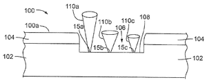
방법 및 레이저 프로세싱 시스템(2)은 기판(102)에서 상이한 표면 효과를 달성하기 위한 3개의 상이한 세트의 레이저 프로세싱 파라미터로 기판(102)을 처리한다. 제1의 세트의 레이저 파라미터는 기판에 리세스(106)를 형성하기 위해 활용된다. 리세스(106)의 표면(108)을 연마하기 위해 제2의 세트의 연마용 레이저 파라미터가 활용될 수 있다. 바람직한 시각적 외관에 대한 조건을 만족하는 광학적 특성을 갖도록 리세스(106)의 연마된 표면(108)을 변형하기 위해 제3의 세트의 표면 변형 레이저 파라미터가 활용될 수 있다.The method and the laser processing system 2 process the substrate 102 with three different sets of laser processing parameters to achieve different surface effects on the substrate 102. A first set of laser parameters is utilized to form the recess 106 in the substrate. A second set of polishing laser parameters may be utilized to polish the surface 108 of the recess 106. A third set of surface modified laser parameters may be utilized to modify the polished surface 108 of the recess 106 to have optical properties that meet the conditions for the desired visual appearance.
Description
관련 출원에 대한 교차 참조Cross-reference to related application
본 출원은 2012년 12월 20일자로 출원된 미국 가출원 제61/740,430호의 가출원이며, 상기 가출원의 내용은 모든 목적을 위해 그들 전체가 참조에 의해 본원에 통합된다.This application is a continuation-in-part of U.S. Provisional Application No. 61 / 740,430, filed December 20, 2012, the contents of which are incorporated herein by reference in their entirety for all purposes.
저작권 표시Copyright indication
ⓒ 2013 Electro Scientific Industries , Inc . 본 특허 문헌의 개시 중 일부는 저작권 보호를 받는 내용을 포함한다. 본 저작권자는, 특허상표청의 특허 파일 또는 기록에 나타나는 한, 특허문헌 또는 특허 개시의 누군가에 의한 팩스 복제에 이의를 갖지 않지만, 그렇지 않으면 어떠한 경우에도 모든 저작권을 유보한다. 37 CFR § 1.71(d).Ⓒ 2013 Electro Scientific Industries, Inc. Some of the disclosures of this patent document include contents subject to copyright protection. The copyright owner has no objection to the copying of the fax by someone in the patent literature or patent disclosure as long as it appears in the patent file or record of the Patent and Trademark Office, but otherwise reserves all copyrights in any case. 37 CFR § 1.71 (d).
기술분야Technical field
본 출원은 레이저 프로세싱에 관한 것으로, 특히, 상이한 세트의 레이저 프로세싱 파라미터로 재료를 프로세싱하여 그 재료에서 상이한 표면 효과를 달성하기 위한 시스템, 방법, 및 장치에 관한 것이다.The present application relates to laser processing, and more particularly, to a system, method, and apparatus for processing materials with different sets of laser processing parameters to achieve different surface effects in the materials.
개요summary
몇몇 실시형태에서, 방법 또는 레이저 시스템은 상이한 세트의 레이저 프로세싱 파라미터로 기판을 처리하여 그 기판에서 상이한 표면 효과를 달성한다.In some embodiments, the method or laser system processes the substrate with a different set of laser processing parameters to achieve different surface effects on the substrate.
몇몇 실시형태에서, 기판에 리세스(recess)를 형성하기 위해 제1의 세트의 리세스 형성용 레이저 파라미터가 활용될 수 있다. 리세스의 표면을 연마하기 위해 제2의 세트의 연마용 레이저 파라미터가 활용될 수 있다. 바람직한 시각적 외관에 대한 조건을 만족하는 광학적 특성을 갖도록 리세스의 연마된 표면을 변형하기 위해 제3의 세트의 표면 변형 레이저 파라미터가 활용될 수 있다.In some embodiments, a first set of laser parameters for recess formation may be utilized to form a recess in the substrate. A second set of polishing laser parameters may be utilized to polish the surface of the recess. A third set of surface modified laser parameters may be utilized to modify the polished surface of the recesses to have optical properties that satisfy the conditions for the desired visual appearance.
몇몇 실시형태에서, 파라미터의 세트 각각은 다른 세트의 값과는 상이한 적어도 하나의 값을 갖는 파라미터를 포함한다.In some embodiments, each set of parameters includes a parameter having at least one value that is different from the other set of values.
몇몇 실시형태에서, 제3의 세트의 표면 변형 레이저 파라미터는, 다른 바람직한 시각적 외관에 대한 조건을 만족하는 다른 광학적 특성을 제공하기 위해 다른 세트의 광학 파라미터를 포함할 수도 있다.In some embodiments, the third set of surface modified laser parameters may include other sets of optical parameters to provide different optical properties that satisfy conditions for other desirable visual appearances.
도 1은 물품에 이미지를 형성하는 프로세스의 일 실시형태를 개략적으로 예시한다.
도 2는 물품에 이미지를 형성하는 프로세스의 다른 실시형태를 개략적으로 예시한다.
도 3은 물품에 이미지를 형성하는 프로세스의 또 다른 실시형태를 개략적으로 예시한다.
도 3a 및 도 3b는 도 3에 의해 나타낸 프로세스에 의해 형성된 물품에서의 이미지의 정면 입면도 및 측면 입면도이다.
도 4는 물품에 이미지를 형성하는 프로세스의 또 다른 실시형태를 개략적으로 예시한다.
도 4a 및 도 4b는 도 4에 의해 나타낸 프로세스에 의해 형성된 물품에서의 이미지의 정면 입면도 및 측면 입면도이다.
도 5a 및 도 5b는 예시적인 레이저 프로세싱 시스템을 예시한다.
도 6은 도 5a 및 도 5b의 레이저 프로세싱 시스템의 소정의 컴포넌트를 강조하는 개략도이다.
도 7은 레이저 프로세싱 시스템에 의해 생성된 레이저 출력의 빔 웨이스트(beam waist)의 확대도이다.Figure 1 schematically illustrates one embodiment of a process for forming an image on an article.
Figure 2 schematically illustrates another embodiment of a process for forming an image on an article.
Figure 3 schematically illustrates another embodiment of a process for forming an image on an article.
3A and 3B are a front elevational view and a side elevational view of an image in an article formed by the process shown by Fig.
Figure 4 schematically illustrates another embodiment of a process for forming an image on an article.
4A and 4B are a front elevational view and a side elevational view of an image in an article formed by the process shown by Fig.
Figures 5A and 5B illustrate an exemplary laser processing system.
Figure 6 is a schematic diagram highlighting certain components of the laser processing system of Figures 5A and 5B.
Figure 7 is an enlarged view of the beam waist of the laser output produced by the laser processing system.
실시형태의 상세한 설명Detailed Description of Embodiments
첨부의 도면을 참조로 예시의 실시형태가 하기에 설명된다. 본 개시의 취지와 교시를 벗어나지 않으면서 많은 상이한 형태 및 실시형태가 가능하며 따라서 본 개시는 본원에 설명된 예시적인 실시형태로 제한되는 것으로 간주되어선 안된다. 오히려, 이들 예시적인 실시형태가 제공됨으로써, 본 개시는 철저하고 완벽하게 될 것이고, 당업자들에게 본 개시의 범위를 전달할 것이다. 도면에서, 컴포넌트의 사이즈와 상대적 사이즈는 명확화를 위해 과장될 수도 있다. 본원에서 사용된 전문 용어는 특정한 예시적인 실시형태를 설명하려는 목적이며, 제한하는 것으로 의도된 것은 아니다. 본원에서 사용된 바와 같이, 단수 형태의 "하나", "일" 및 "그"는, 문맥상 명확히 그렇지 않다고 나타내지 않는 한, 복수의 형태도 또한 포함하도록 의도된다. 용어 "포함한다" 및/또는 "포함하는"은, 본 명세서에서 사용될 때, 언급된 특징, 정수, 단계, 동작, 소자, 및/또는 컴포넌트의 존재를 특정하지만, 하나 이상의 다른 특징, 정수, 단계, 동작, 소자, 컴포넌트, 및/또는 이들의 그룹의 존재 또는 추가를 배제하는 것은 아님이 더 이해될 것이다. 그렇지 않다고 특정되지 않는 한, 값의 범위가 기술될 때, 그 값의 범위는 그 범위의 상한 및 하한 양자뿐만 아니라, 그들 사이의 임의의 부분 범위도 포함한다.Exemplary embodiments are described below with reference to the accompanying drawings. Many different forms and embodiments are possible without departing from the spirit and teachings of the present disclosure, and the present disclosure should therefore not be construed as limited to the exemplary embodiments described herein. Rather, these exemplary embodiments are provided so that this disclosure will be thorough and complete, and will convey the scope of the disclosure to those skilled in the art. In the drawings, the size and relative size of components may be exaggerated for clarity. The terminology used herein is for the purpose of describing particular illustrative embodiments and is not intended to be limiting. As used herein, the singular forms "a", "an" and "the" are intended to also include the plural forms, unless the context clearly dictates otherwise. The phrase "comprises" and / or "comprising" when used in this specification specifies the presence of stated features, integers, steps, operations, elements, and / or components but may include one or more other features, , Operations, elements, components, and / or groups of elements described herein. Unless otherwise specified, when a range of values is stated, the range of values includes both the upper and lower limits of the range, as well as any subranges therebetween.
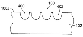
도 1은 물품에 이미지를 형성하는 프로세스의 일 실시형태를 개략적으로 예시한다. 도 1을 참조하면, 예비적인 시각적 외관을 갖는 표면(100a)을 구비하는 물품(100)은, 레이저 조각 파라미터를 갖는 레이저 펄스(11)(도 6)의 빔(110a)을 사용하여 기계가공되어 예비적인 시각적 외관과는 상이한 변형된 시각적 외관을 갖는 문자 또는 이미지를 형성하게 될 수도 있다. 예시된 실시형태에서, 물품(100)은 기판(102)(예를 들면, 알루미늄 또는 알루미늄 합금으로 형성됨) 및 기판(102)의 표면 상에 배치된 층(104)(예를 들면, 알루미늄 산화물로 형성됨)을 포함한다. 기판(102)의 또는 물품(100)의 표면(100a)은 평활할 수도 있거나 또는 (예를 들면, 비드 블라스팅 처리의 결과로서) 거칠 수도 있다. 다른 실시형태에서, 층(104)은 생략될 수도 있다(예를 들면, 그 결과 물품(100)의 표면(100a)은 기판(102)의 표면이 된다).Figure 1 schematically illustrates one embodiment of a process for forming an image on an article. Referring to Figure 1, an
본원에서 기판(102)이 알루미늄 또는 알루미늄 합금의 예로서 설명되지만, 본원에서 설명되는 프로세스는 금속 및 금속 합금에 대해서도 일반적으로 작용할 것임을 알 수 있을 것이다. 다른 예시적인 금속은 스테인리스 스틸 또는 티타늄 또는 이들의 합금을 포함한다.Although the
변형된 시각적 외관을 형성하기 위해, 층(104)을 제거하고 그 아래의 기판(102)을 기계가공하여 기판(102)의 표면에서 10미크론(㎛) 이상(예를 들면, 10대의 ㎛)의 깊이까지 연장하고 오목면(108)에서 종단하는 리세스(106)를 형성하도록, 레이저 펄스(11)의 빔(110a)이 물품(100) 상으로 지향될 수도 있다. 이 프로세스는 본원에서 "조각 프로세스(engraving process)"로 칭해질 수도 있다.The
몇몇 실시형태에서, 조각 프로세스 파라미터는 약 10㎛에서 약 100㎛까지의 범위 내의 깊이를 갖는 리세스(300)를 형성한다. 몇몇 실시형태에서, 깊이는 약 10㎛에서 약 50㎛까지의 범위 내에 있다. 몇몇 실시형태에서, 깊이는 약 10㎛에서 약 25㎛까지의 범위 내에 있다.In some embodiments, the engraving process parameter forms a
일 실시형태에서, 리세스(106)는 이미지가 형성될 물품(100) 영역에 걸쳐 레이저 펄스(11)의 빔(110a)을 다수 회 래스터 주사하는 것에 의해 형성된다. 레이저 펄스(11)의 빔(110a)의 파라미터는, 적어도 수 미크론의 층이 각각의 패스(pass)를 통해 기판(102)으로부터 제거되어, 아주 평활한 표면을 갖는 오목면(108)이 되도록 선택된다. 일 실시형태에서, 오목면(108)의 평활화를 향상시키기 위해, 주사는 다양한 각도에서 그리고 다양한 스팟 중첩도를 가지고 이루어질 수도 있다.In one embodiment, the
조각 프로세스는, 기판(102)의 표면에 레이저 스팟을 갖는 레이저 펄스(11)를 포함하는 레이저 출력을 갖는 레이저 조각 파라미터를 구비하며, 레이저 스팟(15a)은 약 20㎛와 약 125㎛ 사이의 범위 내의 스팟 직경을 포함하는 스팟 사이즈를 갖는다. 몇몇 실시형태에서, 스팟 직경은 약 60㎛와 약 110㎛ 사이의 범위 내에 있다. 몇몇 실시형태에서, 스팟 직경은 약 75㎛와 약 100㎛ 사이의 범위 내에 있다. 편의상, 용어 "스팟 직경"은, 타원의 레이저 스팟과 같은, 원형이 아닌 레이저 스팟의 주 공간축을 포함할 뿐만 아니라, 원형의 레이저 스팟의 직경도 포함한다.The engraving process comprises a laser engraving parameter with a laser power including a
몇몇 실시형태에서, 레이저 조각 파라미터는 약 300 나노미터(㎚)와 약 2㎛ 사이의 레이저 파장을 갖는 레이저 출력을 포함한다. 몇몇 실시형태에서, 레이저 출력은 적외선 레이저 파장을 갖는다. 몇몇 실시형태에서, 레이저 출력은 약 1152㎚, 1090㎚, 1080㎚, 1064㎚, 1060㎚, 1053㎚, 1047㎚, 980㎚, 799㎚, 또는 753㎚의 레이저 파장을 갖는다. 몇몇 실시형태에서, 레이저 출력은 약 1150㎚ 와 1350㎚, 780㎚ 와 905㎚, 또는 700㎚ 와 1000㎚ 사이의 레이저 파장을 갖는다. 몇몇 실시형태에서, 레이저 출력은 약 700㎚와 1350㎚ 사이의 레이저 파장을 갖는다. 몇몇 실시형태에서, 레이저 출력은 약 980㎚와 1320㎚ 사이의 레이저 파장을 갖는다. 몇몇 실시형태에서, 레이저 출력은 약 980㎚와 1080㎚ 사이의 레이저 파장을 갖는다. 몇몇 실시형태에서, 레이저 출력은 약 1064㎚의 레이저 파장을 갖는다. 몇몇 실시형태에서, 레이저 출력은 적외선 고체-상태 레이저에 의해 제공된다. 몇몇 실시형태에서, 레이저 출력은 다이오드 여기 적외선 고체-상태 레이저에 의해 제공된다. 몇몇 실시형태에서, 레이저 출력은 적외선 광섬유 레이저에 의해 제공된다.In some embodiments, the laser engraving parameter comprises a laser output having a laser wavelength between about 300 nanometers (nm) and about 2 micrometers. In some embodiments, the laser output has an infrared laser wavelength. In some embodiments, the laser output has a laser wavelength of about 1152 nm, 1090 nm, 1080 nm, 1064 nm, 1060 nm, 1053 nm, 1047 nm, 980 nm, 799 nm, or 753 nm. In some embodiments, the laser output has a laser wavelength between about 1150 nm and 1350 nm, between 780 nm and 905 nm, or between 700 nm and 1000 nm. In some embodiments, the laser output has a laser wavelength between about 700 nm and 1350 nm. In some embodiments, the laser output has a laser wavelength between about 980 nm and 1320 nm. In some embodiments, the laser output has a laser wavelength between about 980 nm and 1080 nm. In some embodiments, the laser output has a laser wavelength of about 1064 nm. In some embodiments, the laser output is provided by an infrared solid-state laser. In some embodiments, the laser output is provided by a diode-excited infrared solid-state laser. In some embodiments, the laser output is provided by an infrared fiber laser.
몇몇 실시형태에서, 레이저 조각 파라미터는 약 500펨토초(fs)에서 약 200나노초(㎱)까지의 범위 내에 있는 펄스폭(펄스 지속시간)을 갖는 레이저 펄스(11)를 포함하는 레이저 출력을 갖는다. 몇몇 실시형태에서, 펄스폭은 약 1㎱에서 약 125나노초까지의 범위를 갖는다. 몇몇 실시형태에서, 펄스폭은 약 10㎱에서 약 100㎱까지의 범위를 갖는다.In some embodiments, the laser engraving parameter has a laser power including a
몇몇 실시형태에서, 레이저 조각 파라미터는 50㎑보다 더 큰 펄스 반복률로 물품 상에 레이저 펄스(11)를 지향시키는 것을 포함한다. 몇몇 실시형태에서, 펄스 반복률은 약 50㎑에서 약 1000㎑까지의 범위 내에 있다. 몇몇 실시형태에서, 펄스 반복률은 약 75㎑에서 약 500㎑까지의 범위 내에 있다. 몇몇 실시형태에서, 펄스 반복률은 약 100㎑에서 약 200㎑까지의 범위 내에 있다.In some embodiments, the laser engraving parameter includes directing the
일반적으로, 레이저 조각 파라미터는 기판(102)에 걸친 다중 패스의 레이저 출력을 주사하는 것을 포함한다. 그러나, 몇몇 실시형태에서, 기판(102)에 걸친 단일 패스의 레이저 출력이 원하는 깊이의 오목면(108)을 달성하기에 충분할 수도 있다.Generally, laser engraving parameters include scanning multiple passes of laser power across the
레이저 조각 프로세스의 일 실시형태에서, 레이저 펄스(11)는 20㎛와 125㎛ 사이의 범위 내에 있는 스팟 직경, 약 980㎚와 1320㎚ 사이의 파장, 약 1㎱에서 100㎱까지의 범위 내에 있는 펄스폭, 및 50㎑에서 500㎑까지의 범위 내에 있는 펄스 반복률을 가질 수도 있다.In one embodiment of the laser engraving process, the
레이저 조각 프로세스의 다른 실시형태에서, 레이저 펄스(11)는 50㎛와 100㎛ 사이의 범위 내에 있는 스팟 직경, 약 1047㎚와 1090㎚ 사이의 파장, 약 10㎱에서 100㎱까지의 범위 내에 있는 펄스폭, 및 100㎑에서 200㎑까지의 범위 내에 있는 펄스 반복률을 가질 수도 있다.In another embodiment of the laser engraving process, the
오목면(108)을 형성하는 레이저 조각 프로세스는 기판(102)이 조각된 시각적 외관을 가지도록 기판(102)의 시각적 외관을 변형한다.The laser engraving process that forms the
오목면(108)을 형성한 이후, 레이저 펄스(11)의 빔(110b)이 오목면(108) 상에 지향되어 그것을 고도로 연마된 오목면으로 변환할 수도 있다. 이 프로세스는 본원에서 "연마 프로세스"로 칭해질 수도 있다. 몇몇 실시형태에서, 레이저 연마 파라미터는 약 100μJ에서 약 2000μJ까지의 범위 내에 있는 펄스 에너지를 갖는 레이저 펄스(11)를 구비하는 레이저 출력을 포함한다. 몇몇 실시형태에서, 펄스 에너지는 약 250μJ에서 약 1500μJ까지의 범위 내에 있다. 몇몇 실시형태에서, 펄스 에너지는 약 500μJ에서 약 1000μJ까지의 범위 내에 있다.After forming the
몇몇 실시형태에서, 레이저 연마 파라미터는 50㎑보다 더 큰 펄스 반복률로 오목면(108) 상에 레이저 펄스(11)를 지향시키는 것을 포함한다. 몇몇 실시형태에서, 펄스 반복률은 100㎑보다 더 크다. 몇몇 실시형태에서, 펄스 반복률은 약 50㎑에서 약 10,000㎑까지의 범위 내에 있다. 몇몇 실시형태에서, 펄스 반복률은 약 75㎑에서 약 5,000㎑까지의 범위 내에 있다. 몇몇 실시형태에서, 펄스 반복률은 약 100㎑에서 약 2,000㎑까지의 범위 내에 있다.In some embodiments, the laser abrasive parameters include directing the
몇몇 실시형태에서, 레이저 연마 파라미터는 적외선 영역 밖의 레이저 파장을 갖는 레이저 출력을 포함한다. 몇몇 실시형태에서, 레이저 출력은 가시 레이저 파장을 갖는다. 몇몇 실시형태에서, 레이저 출력은 약 400㎚와 약 700㎚ 사이의 레이저 파장을 갖는다. 몇몇 실시형태에서, 레이저 출력은 약 694㎚, 676㎚, 647㎚, 660-635㎚, 633㎚, 628㎚, 612㎚, 594㎚, 578㎚, 568㎚, 543㎚, 532㎚, 530㎚, 514㎚, 511㎚, 502㎚, 497㎚, 488㎚, 476㎚, 458㎚, 442㎚, 428㎚, 또는 416㎚의 레이저 파장을 갖는다. 몇몇 실시형태에서, 레이저 출력은 약 476㎚와 약 569㎚ 사이의 레이저 파장을 갖는다. 몇몇 실시형태에서, 레이저 출력은 녹색 레이저 파장을 갖는다. 몇몇 실시형태에서, 레이저 출력은 약 532㎚ 또는 약 511㎚인 레이저 파장을 갖는다. 몇몇 실시형태에서, 레이저 출력은 녹색 고체 상태 레이저에 의해 제공된다. 몇몇 실시형태에서, 레이저 출력은 다이오드 여기 녹색 고체 상태 레이저에 의해 제공된다. 몇몇 실시형태에서, 레이저 출력은 광섬유 레이저에 의해 제공된다.In some embodiments, the laser ablation parameter comprises a laser output having a laser wavelength outside the infrared region. In some embodiments, the laser output has a visible laser wavelength. In some embodiments, the laser output has a laser wavelength between about 400 nm and about 700 nm. In some embodiments, the laser power is about 694nm, 676nm, 647nm, 660-635nm, 633nm, 628nm, 612nm, 594nm, 578nm, 568nm, 543nm, 532nm, 514 nm, 511 nm, 502 nm, 497 nm, 488 nm, 476 nm, 458 nm, 442 nm, 428 nm, or 416 nm. In some embodiments, the laser power has a laser wavelength between about 476 nm and about 569 nm. In some embodiments, the laser output has a green laser wavelength. In some embodiments, the laser power has a laser wavelength of about 532 nm or about 511 nm. In some embodiments, the laser output is provided by a green solid state laser. In some embodiments, the laser output is provided by a diode-excited green solid-state laser. In some embodiments, the laser output is provided by a fiber laser.
몇몇 실시형태에서, 레이저 연마 파라미터는, 조각 프로세스 동안 활용된 스팟 직경보다 더 작은 스팟 직경을 갖는 레이저 스팟(15b)을 오목면(108)에 갖는 레이저 펄스(11)를 포함한다. 레이저 연마 프로세스의 몇몇 실시형태에서, 스팟 직경은 약 5미크론과 약 50㎛ 사이의 범위 내에 있다. 몇몇 실시형태에서, 스팟 직경은 약 15㎛와 약 40㎛ 사이의 범위 내에 있다. 몇몇 실시형태에서, 스팟 직경은 약 25㎛와 약 35㎛ 사이의 범위 내에 있다. 몇몇 실시형태에서, 스팟 직경은 약 30㎛이다.In some embodiments, the laser ablation parameter comprises a
몇몇 실시형태에서, 레이저 연마 파라미터는 오목면(108)에 걸친 단일 패스의 레이저 출력을 주사하는 것을 포함한다. 몇몇 실시형태에서, 레이저 연마 파라미터는 오목면(108)에 걸친 다중 패스의 레이저 출력을 주사(예컨대 래스터 주사)하는 것을 포함한다.In some embodiments, the laser abrasive parameters include scanning a single pass laser output across the
몇몇 실시형태에서, 레이저 연마 파라미터는, 약 75%와 98% 사이만큼 서로 중첩하는 레이저 스팟(15b)에서 오목면(108) 상에 충돌하는 연속적으로 지향된 레이저 펄스(11)를 포함할 수도 있다. 몇몇 실시형태에서, 연속적인 레이저 스팟(15b)은 약 85%와 95% 사이만큼 중첩한다. 몇몇 실시형태에서, 연속적인 레이저 스팟(15b)은 약 88%와 92% 사이만큼 중첩한다. 몇몇 실시형태에서, 연속적인 레이저 스팟(15b)은 약 90%만큼 중첩한다.In some embodiments, the laser abrasive parameters may include successively directed
레이저 연마 프로세스의 일 실시형태에서, 레이저 펄스(11)는 약 25㎛와 약 35㎛ 사이의 범위 내에 있는 스팟 직경, 녹색 파장, 약 100μJ에서 약 1000μJ까지의 범위 내에 있는 펄스 당 에너지, 약 500㎑에서 약 2,000㎑까지의 범위 내에 있는 펄스 반복률, 및 약 88%와 92% 사이의 레이저 스팟 중첩을 가질 수도 있다.In one embodiment of the laser ablation process, the
레이저 연마 프로세스의 다른 실시형태에서, 레이저 펄스(11)는 약 30㎛의 스팟 직경, 약 532㎚의 파장, 약 500μJ에서 약 1000μJ까지의 범위 내에 있는 펄스 당 에너지, 100㎑보다 더 큰 펄스 반복률, 및 약 90%의 레이저 스팟 중첩을 가질 수도 있다.In another embodiment of the laser ablation process, the
연마 프로세스는, 표면(100a)에 나타내어질 때, 오목면(108)의 조각된 시각적 외관과는 상이하고 그리고 물품(100)의 예비적인 시각적 외관과는 상이한 연마된 시각적 외관을 오목면(108)에 부여하도록, 오목면(108)의 시각적 외관을 변형한다. 특히, 연마된 또는 평활화된 표면은 실질적으로 반사성일 수도 있으며 사람의 눈에 아주 밝게 보이도록 의도된다.The abrasive process is shown as a
도 2는 물품(100)에 이미지를 형성하는 프로세스의 다른 실시형태를 개략적으로 예시한다. 도 2를 참조하면, 위에서 논의된 조각 및 연마 프로세스가 수행된, 물품(100)과 같은 물품은, 연마된 오목면(108)의 연마된 시각적 외관을 더 변형하기 위해 레이저 펄스(11)의 빔(110c)을 사용하여 더 기계가공될 수도 있다. 이렇게 더 변형된 시각적 외관은 도 1에서 논의된 변형된 시각적 외관과는 상이할 수도 있다. 이 프로세스는 본원에서 "표면 변형 프로세스"로 칭해질 수도 있다.Figure 2 schematically illustrates another embodiment of a process for forming an image on an
예를 들면, 몇몇 실시형태에서, 연마된 오목면(108)에 지향되고 그것에 걸쳐 주사되는 레이저 펄스(11)는, 빛을 흡수하도록 구조화된 주기적 구조체, 나노입자(예를 들면, 기판(102)을 형성하는 재료를 포함함) 등 또는 이들의 조합을 생성하도록 구성될 수도 있다. 이 프로세스는 본원에서 "암화 프로세스(darkening process)"로 칭해질 수도 있다.For example, in some embodiments, the
암화 프로세스 동안 연마된 오목면(108) 상에 지향된 레이저 펄스(11)는, 상대적으로 짧은 펄스 지속시간을 포함하고, 상대적으로 작은 레이저 스팟 직경을 가지며, 상대적으로 느린 주사 속도에서 적용될 수도 있고, 연속 주사 사이의 상대적으로 가깝게 이격된 피치에서 적용될 수도 있는 레이저 프로세싱 파라미터를 가질 수도 있다.The
몇몇 실시형태에서, 레이저 암화 파라미터는 약 500fs에서 약 100㎱까지의 범위 내에 있는 펄스 지속시간을 포함한다. 몇몇 실시형태에서, 펄스 지속시간은 약 1피코초(㎰)에서 약 50㎱까지의 범위 내에 있다. 몇몇 실시형태에서, 펄스 지속시간은 약 1피코초(㎰)에서 약 25㎱까지의 범위 내에 있다. 몇몇 실시형태에서, 펄스 지속시간은 약 1㎰에서 약 10㎱까지의 범위 내에 있다.In some embodiments, the laser annealing parameters include pulse durations in the range of about 500 fs to about 100 fs. In some embodiments, the pulse duration is in the range of about 1 picosecond (㎰) to about 50 picoseconds. In some embodiments, the pulse duration is in the range of about 1 picosecond (?) To about 25 picoseconds. In some embodiments, the pulse duration is in the range of about 1 kV to about 10 kV.
몇몇 실시형태에서, 레이저 암화 파라미터는 조각 프로세스 동안 활용된 스팟 직경보다 더 작거나 또는 연마 프로세스 동안 활용된 스팟 직경보다 더 작은 레이저 스팟(15c)의 스팟 직경을 포함한다. 레이저 연마 프로세스의 몇몇 실시형태에서, 스팟 직경은 약 1미크론과 약 50㎛사이의 범위 내에 있다. 몇몇 실시형태에서, 스팟 직경은 약 30㎛보다 더 작다. 몇몇 실시형태에서, 스팟 직경은 약 1㎛와 약 30㎛ 사이의 범위 내에 있다. 몇몇 실시형태에서, 스팟 직경은 약 1㎛와 약 20㎛ 사이의 범위 내에 있다. 몇몇 실시형태에서, 스팟 직경은 약 1㎛와 약 10㎛ 사이의 범위 내에 있다.In some embodiments, the laser annealing parameters include spot diameters of the
몇몇 실시형태에서, 암화 프로세스 파라미터는 10㎑보다 더 큰 펄스 반복률로 물품 상에 레이저 펄스(11)를 지향시키는 것을 포함한다. 몇몇 실시형태에서, 펄스 반복률은 약 10㎑에서 약 1000㎑까지의 범위 내에 있다. 몇몇 실시형태에서, 펄스 반복률은 약 100㎑에서 약 500㎑까지의 범위 내에 있다. 몇몇 실시형태에서, 펄스 반복률은 약 100㎑에서 약 300㎑까지의 범위 내에 있다. 몇몇 실시형태에서, 펄스 반복률은 약 100㎑이다.In some embodiments, the darkening process parameters include directing the
몇몇 실시형태에서, 암화 프로세스는 약 0.5W에서 약 50W까지의 범위 내에 있는 파워를 나타내는 레이저 펄스(11)를 포함한다. 몇몇 실시형태에서, 파워는 약 1W에서 약 10W까지의 범위 내에 있다. 몇몇 실시형태에서, 파워는 약 2W에서 약 8W까지의 범위 내에 있다. 몇몇 실시형태에서, 파워는 약 5W이다.In some embodiments, the darkening process comprises a
몇몇 실시형태에서, 레이저 암화 파라미터는 약 1㎜/sec와 약 5000㎜/sec 사이의 범위 내에 있는 주사 속도에서의 레이저 펄스(11)의 적용을 포함한다. 몇몇 실시형태에서, 주사 속도는 약 5㎜/sec와 약 500㎜/sec 사이의 범위 내에 있다. 몇몇 실시형태에서, 주사 속도는 약 10㎜/sec와 약 50㎜/sec 사이의 범위 내에 있다. 몇몇 실시형태에서, 주사 속도는 약 12㎜/sec와 약 40㎜/sec 사이의 범위 내에 있다. 몇몇 실시형태에서, 주사 속도는 약 15㎜/sec와 약 35㎜/sec 사이의 범위 내에 있다. 몇몇 실시형태에서, 주사 속도는 약 25㎜/sec이다.In some embodiments, the laser annealing parameters include the application of the
몇몇 실시형태에서, 레이저 암화 파라미터는 약 0.5㎛와 약 50㎛ 사이의 범위 내에 있는 (연속 주사 사이의) 피치에서의 레이저 펄스(11)의 적용을 포함한다. 몇몇 실시형태에서, 연속 주사 사이의 피치는 약 1㎛와 약 30㎛ 사이의 범위 내에 있다. 몇몇 실시형태에서, 연속 주사 사이의 피치는 약 5㎛와 약 15㎛ 사이의 범위 내에 있다. 몇몇 실시형태에서, 연속 주사 사이의 피치는 약 10㎛이다.In some embodiments, the laser annealing parameters include the application of the
일 실시형태에서, 레이저 암화 파라미터는 약 1㎰에서 약 10㎱까지의 범위 내에 있는 펄스 지속시간, 약 30㎛ 미만의 스팟 직경, 약 1㎜/sec와 약 50㎜/sec 사이의 범위 내에 있는 주사 속도, 및 약 1㎛와 약 30㎛ 사이의 범위 내에 있는 연속 주사 사이의 피치를 포함한다.In one embodiment, the laser annealing parameter is selected from the group consisting of a pulse duration in the range of about 1 kPa to about 10 kPa, a spot diameter of less than about 30 mu m, a scan within a range of between about 1 mm / sec and about 50 mm / Speed, and a pitch between successive scans that are in the range between about 1 [mu] m and about 30 [mu] m.
일 실시형태에서, 레이저 암화 파라미터는 약 1㎰에서 약 10㎱까지의 범위 내에 있는 펄스 지속시간, 약 1㎛와 약 30㎛ 사이의 범위 내에 있는 스팟 직경, 약 15㎜/sec와 약 35㎜/sec 사이의 범위 내에 있는 주사 속도, 및 약 5㎛와 약 15㎛ 사이의 범위 내에 있는 연속 주사 사이의 피치를 포함한다.In one embodiment, the laser annealing parameters include a pulse duration in the range of about 1 kPa to about 10 kPa, a spot diameter in the range of between about 1 [mu] m and about 30 [mu] m, sec, and a pitch between successive scans that are in the range between about 5 [mu] m and about 15 [mu] m.
일 실시형태에서, 레이저 암화 파라미터는 약 1㎰에서 약 10㎱까지의 범위 내에 있는 펄스 지속시간, 약 1㎛와 약 30㎛ 사이의 범위 내에 있는 스팟 직경, 약 25㎜/sec인 주사 속도, 및 약 10㎛인 연속 주사 사이의 피치를 포함한다.In one embodiment, the laser annealing parameter comprises a pulse duration in the range of about 1 kPa to about 10 kPa, a spot diameter in the range of about 1 [mu] m to about 30 [mu] m, a scan rate of about 25 mm / And a pitch between consecutive scans of about 10 mu m.
따라서, 연마된 오목면(108)에 대한 암화 프로세스의 수행시, 더 변형된 시각적 외관이 오목면(108)에 부여되는데, 이것은 물품(100)의 예비적인 시각적 외관과는 상이하고, 표면(100a)에 나타내어질 때, 조각된 시각적 외관과는 상이하고, 연마된 오목면(108)의 연마된 시각적 외관과는 상이하다. 특히, 암화 프로세스는 빛을 흡수하고 오목면(108)이 사람 눈에 검게 보이게 하도록 의도된다.A more deformed visual appearance is imparted to the
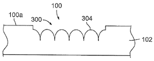
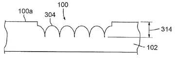
도 3은 물품(100)에 이미지를 형성하는 프로세스의 또 다른 실시형태를 개략적으로 예시한다. 도 3a 및 도 3b는 도 3에 의해 나타낸 프로세스에 의해 형성된 물품에서의 이미지의 정면 입면도 및 측면 입면도이다. 도 3, 도 3a, 및 도 3b를 참조하면, 예비적인 시각적 외관을 갖는 표면(100a)을 구비하는 물품(100)이 레이저 펄스(11)의 빔을 사용하여 기계가공되어, 예비적인 시각적 외관과는 상이한 변형된 시각적 외관을 갖는 문자 또는 이미지를 형성할 수도 있다. 예시된 실시형태에서, 물품(100)은, 도 1 및 도 2에 관해 위에서 논의된 조각 및 연마 프로세스를 기판(102)에 수행하는 것에 의해 제공될 수도 있거나, 또는 다르게 제공될 수도 있다.3 schematically illustrates another embodiment of a process for forming an image on an
예를 들면, 몇몇 실시형태에서, 기판(102), 층(104), 또는 기판(102)과 층(104)을 용융, 제거 또는 다르게는 성형 또는 기계가공하여, 서로 교차하며 물품(100)의 표면에서부터 수 미크론의 깊이(314)까지 연장하는 리세스(300)의 네트워크를 형성하도록, 레이저 펄스(11)의 빔이 물품(100) 상에 지향될 수도 있다. 이 표면 변형 프로세스는 본원에서 "크로스 해칭 프로세스(cross-hatching process)"로 칭해질 수도 있다.For example, in some embodiments, the
몇몇 실시형태에서, 리세스(300)는, 이미지가 형성될 물품(100)의 영역에 걸쳐 레이저 펄스(11)의 빔을 (예를 들면, 화살표(302)에 의해 나타내어진 다양한 방향으로) 다수 회 주사하는 것에 의해 형성된다. 이 이미지는 오목면(108) 내에 또는 기판(102) 또는 물품(100)의 표면(100a) 내에 형성될 수도 있다. 몇몇 실시형태에서, 화살표(302)에 의해 나타내어진 주사 방향은 평행선을 따라 연장할 수도 있다. 몇몇 실시형태에서, 화살표(302)에 의해 나타내어진 주사 방향은 물품(100)의 에지에 평행한 평행선을 따라 연장할 수도 있다. 몇몇 실시형태에서, 주사 방향은 곡선의 평행선(도시되지 않음)을 따라 연장할 수도 있다. 몇몇 실시형태에서, 주사 방향은 수직이 아닌 횡방향(도시되지 않음)을 따라 연장할 수도 있다. 몇몇 실시형태에서, 화살표(302)에 의해 나타내어진 주사 방향은 상호 수직인 방향을 따라 연장할 수도 있다.In some embodiments, the
몇몇 실시형태에서, 크로스 해칭 프로세스 파라미터는 약 1㎛에서 약 50㎛까지의 범위 내에 있는 인접한 리세스(300) 사이의 중심 대 중심 간격(310 또는 312)을 포함한다. 몇몇 실시형태에서, 인접한 리세스(300) 사이의 중심 대 중심 간격은 약 5㎛에서 약 30㎛까지의 범위 내에 있다. 몇몇 실시형태에서, 인접한 리세스(300) 사이의 중심 대 중심 간격은 약 10㎛에서 약 20㎛까지의 범위 내에 있다. 주사 사이의 간격 또는 피치(310 또는 312)는 인접한 리세스(300) 사이의 중심 대 중심 간격과 동일하거나 또는 상이할 수도 있다. 또한, 인접한 리세스(300) 사이의 중심 대 중심 간격은 횡방향에서 상이할 수도 있으며, 주사 사이의 간격 또는 피치(310 또는 312)는 횡방향 사이에서 상이할 수도 있다.In some embodiments, the cross hatching process parameters include a center-to-
몇몇 실시형태에서, 크로스 해칭 프로세스 파라미터는 적외선 영역 밖의 레이저 파장을 갖는 레이저 출력을 포함한다. 몇몇 실시형태에서, 레이저 출력은 가시 레이저 파장을 갖는다. 몇몇 실시형태에서, 레이저 출력은 약 400㎚와 약 700㎚ 사이의 레이저 파장을 갖는다. 몇몇 실시형태에서, 레이저 출력은 약 694㎚, 676㎚, 647㎚, 660-635㎚, 633㎚, 628㎚, 612㎚, 594㎚, 578㎚, 568㎚, 543㎚, 532㎚, 530㎚, 514㎚, 511㎚, 502㎚, 497㎚, 488㎚, 476㎚, 458㎚, 442㎚, 428㎚, 또는 416㎚의 레이저 파장을 갖는다. 몇몇 실시형태에서, 레이저 출력은 약 476㎚와 약 569㎚ 사이의 레이저 파장을 갖는다. 몇몇 실시형태에서, 레이저 출력은 녹색 레이저 파장을 갖는다. 몇몇 실시형태에서, 레이저 출력은 약 532㎚ 또는 약 511㎚인 레이저 파장을 갖는다. 몇몇 실시형태에서, 레이저 출력은 녹색 고체 상태 레이저에 의해 제공된다. 몇몇 실시형태에서, 레이저 출력은 다이오드 여기 녹색 고체 상태 레이저에 의해 제공된다. 몇몇 실시형태에서, 레이저 출력은 광섬유 레이저에 의해 제공된다.In some embodiments, the cross hatching process parameters include a laser output having a laser wavelength outside the infrared region. In some embodiments, the laser output has a visible laser wavelength. In some embodiments, the laser output has a laser wavelength between about 400 nm and about 700 nm. In some embodiments, the laser power is about 694nm, 676nm, 647nm, 660-635nm, 633nm, 628nm, 612nm, 594nm, 578nm, 568nm, 543nm, 532nm, 514 nm, 511 nm, 502 nm, 497 nm, 488 nm, 476 nm, 458 nm, 442 nm, 428 nm, or 416 nm. In some embodiments, the laser power has a laser wavelength between about 476 nm and about 569 nm. In some embodiments, the laser output has a green laser wavelength. In some embodiments, the laser power has a laser wavelength of about 532 nm or about 511 nm. In some embodiments, the laser output is provided by a green solid state laser. In some embodiments, the laser output is provided by a diode-excited green solid-state laser. In some embodiments, the laser output is provided by a fiber laser.
몇몇 실시형태에서, 크로스 해칭 프로세스 파라미터는, 약 25㎛와 약 200㎛ 사이의 범위 내에 있는 스팟 직경을 포함하는 스팟 사이즈를 갖는 레이저 스팟을 구비하는 레이저 출력을 포함한다. 몇몇 실시형태에서, 스팟 직경은 약 40㎛와 약 125㎛ 사이의 범위 내에 있다. 몇몇 실시형태에서, 스팟 직경은 약 50㎛와 약 100㎛ 사이의 범위 내에 있다.In some embodiments, the cross hatching process parameter includes a laser output having a laser spot having a spot size that includes a spot diameter in a range between about 25 [mu] m and about 200 [mu] m. In some embodiments, the spot diameter is in the range between about 40 占 퐉 and about 125 占 퐉. In some embodiments, the spot diameter is in a range between about 50 microns and about 100 microns.
몇몇 실시형태에서, 크로스 해칭 프로세스 파라미터는 약 1㎛에서 약 10㎛까지의 범위 내의 깊이를 갖는 리세스(300)를 형성한다. 몇몇 실시형태에서, 깊이는 약 1㎛에서 약 5㎛까지의 범위 내에 있다. 몇몇 실시형태에서, 깊이는 약 1㎛에서 약 3㎛까지의 범위 내에 있다.In some embodiments, the cross hatching process parameters form a
몇몇 실시형태에서, 레이저 크로스 해칭 프로세스 파라미터는 약 25㎜/sec와 약 150㎜/sec 사이의 범위 내에 있는 주사 속도에서의 레이저 펄스(11)의 적용을 포함한다. 몇몇 실시형태에서, 주사 속도는 약 50㎜/sec와 약 100㎜/sec 사이의 범위 내에 있다. 몇몇 실시형태에서, 주사 속도는 약 60㎜/sec와 약 80㎜/sec 사이의 범위 내에 있다. 몇몇 실시형태에서, 주사 속도는 약 75㎜/sec이다.In some embodiments, the laser cross hatching process parameters include the application of the
몇몇 실시형태에서, 레이저 크로스 해칭 프로세스 파라미터 약 1W에서 약 10W까지의 범위 내에 있는 파워를 나타내는 레이저 펄스(11)를 포함한다. 몇몇 실시형태에서, 파워는 약 2W에서 약 8W까지의 범위 내에 있다. 몇몇 실시형태에서, 파워는 약 3W에서 약 6W까지의 범위 내에 있다. 몇몇 실시형태에서, 파워는 약 4W이다.In some embodiments, the laser cross hatching process parameter includes a
일 실시형태에서, 레이저 크로스 해칭 프로세스 파라미터는 가시 레이저 파장, 약 40㎛와 약 125㎛ 사이의 범위 내에 있는 스팟 직경, 약 50㎜/sec와 약 100㎜/sec 사이의 범위 내에 있는 주사 속도, 약 2W에서 약 8W까지의 범위 내에 있는 파워, 약 5㎛에서 약 30㎛까지의 범위 내에 있는 인접한 리세스(300) 사이의 중심 대 중심 간격, 및 약 5㎛에서 약 30㎛까지의 범위 내에 있는 주사 사이의 피치(310 또는 312)를 갖는 레이저 출력을 포함한다.In one embodiment, the laser cross hatching process parameters include a visible laser wavelength, a spot diameter in the range between about 40 and about 125 micrometers, a scan speed in the range between about 50 mm / sec and about 100 mm / sec, A center-to-center spacing between
일 실시형태에서, 레이저 크로스 해칭 프로세스 파라미터는 녹색 레이저 파장, 약 50㎛와 약 100㎛ 사이의 범위 내에 있는 스팟 직경, 약 60㎜/sec와 약 80㎜/sec 사이의 범위 내에 있는 주사 속도, 약 3W에서 약 6W까지의 범위 내에 있는 파워, 약 10㎛에서 약 20㎛까지의 범위 내에 있는 인접한 리세스(300) 사이의 중심 대 중심 간격, 및 약 10㎛에서 약 20㎛까지의 범위 내에 있는 주사 사이의 피치(310 또는 312)를 갖는 레이저 출력을 포함한다.In one embodiment, the laser cross hatching process parameter is selected from the group consisting of a green laser wavelength, a spot diameter in the range between about 50 and about 100 mu m, a scan speed in the range between about 60 mm / sec and about 80 mm / A center-to-center spacing between
일 실시형태에서, 레이저 크로스 해칭 프로세스 파라미터는 녹색 레이저 파장, 약 50㎛와 약 100㎛ 사이의 범위 내에 있는 스팟 직경, 약 75㎜/sec의 주사 속도, 약 4W의 파워, 약 10㎛에서 약 20㎛까지의 범위 내에 있는 인접한 리세스(300) 사이의 중심 대 중심 간격, 및 약 10㎛에서 약 20㎛까지의 범위 내에 있는 주사 사이의 피치(310 또는 312)를 갖는 레이저 출력을 포함한다.In one embodiment, the laser cross hatching process parameter is selected from the group consisting of a green laser wavelength, a spot diameter in the range between about 50 and about 100 mu m, a scan speed of about 75 mm / sec, a power of about 4 W, Center to center spacing between
크로스 해칭 프로세스의 몇몇 실시형태에서, 레이저 펄스(11)는 그들이 물품(100)에 충돌시 초점이 맞지 않도록 물품(100) 상에 지향된다. 레이저 펄스(11)의 빔이 초점이 맞지 않기 때문에, 스팟 사이즈는 아주 크고 물품(100)의 재료에서 식각되는 선은 중첩할 것이다. 이것으로 인해, 험프(hump) 또는 범프(bump)(304)의 패턴의 상면은 물품(100)의 표면(100a) 아래에 있게 된다.In some embodiments of the cross-hatching process, the
위에서 예시적으로 설명된 크로스 해칭 프로세스의 수행시, 반사성 범프(304)의 패턴이 물품(100) 내에 형성된다. 범프(304)는 (예를 들면, 레이저 펄스(11)의 빔에 의해 용융된 다음 다시 고화된 기판(102)의 재료로 적어도 부분적으로 형성되는) 평활한 표면을 가지며, 안정하고, 내마모성이 있으며 범프(304)의 패턴은 고휘도를 갖는 이미지를 생성한다. 임의의 특정 이론에 얽매이길 원치 않지만, 범프(304)의 패턴에 입사하는 광은 범프(304)에 의해 반사되고 산란되어 범프(304)의 패턴으로부터 반사된 광이 사람 눈에 흰색으로 보이게 된다고 믿어진다. 반사성 범프(304)의 패턴은 원래의 표면(100a)의 것보다, 기판 표면(102)의 것보다, 연마되지 않은 오목면(108)의 것보다, 그리고 연마된 오목면(108)의 것보다 더 밝은 흰색 외관을 제공한다. 또한, 범프(304)의 패턴은 종래의 식각 프로세스에 의해 달성될 수 있는 것보다 더 밝은 흰색을 제공한다. 선행 연마 프로세스 없이 크로스 해칭 프로세스가 수행되는 경우, 범프(304)의 패턴은, 연마 프로세스 이후에 수행되는 경우보다 광택이 덜한 흰색의 무광택 외관을 제공하지만, 무광택의 흰색은 종래의 식각 프로세스에 의해 달성될 수 있는 것보다 여전히 더 밝은 흰색임을 또한 주목한다.In performing the cross-hatching process illustratively described above, a pattern of
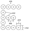
도 4는 물품(100)에 이미지를 형성하는 프로세스의 또 다른 실시형태를 개략적으로 예시한다. 도 4a 및 도 4b는 도 4에 의해 나타낸 프로세스에 의해 형성된 물품에서의 이미지의 정면 입면도 및 측면 입면도이다. 도 4, 도 4a, 및 도 4b를 참조하면, 예비적인 시각적 외관을 갖는 표면(100a)을 구비하는 물품(100)이 레이저 펄스(11)의 빔을 사용하여 기계가공되어, 예비적인 시각적 외관과는 상이한 변형된 시각적 외관을 갖는 문자 또는 이미지를 형성할 수도 있다. 예시된 실시형태에서, 물품(100)은, 도 1 및 도 2에 관해 위에서 논의된 조각 및 연마 프로세스를 기판(102)에 수행하는 것에 의해 제공될 수도 있거나, 또는 다르게 제공될 수도 있다.Figure 4 schematically illustrates another embodiment of a process for forming an image on an
변형된 시각적 외관을 형성하기 위해, 기판(102), 층(104), 또는 기판(102)과 층(104)을 용융, 제거 또는 다르게는 성형 또는 기계가공하여, 물품(100)의 표면(100a)에서부터 기판(102)의 표면 아래의 또는 오목면(108) 아래의 깊이까지 연장하는 비중첩 리세스(402)의 패턴(400)을 형성하도록, 레이저 펄스(11)의 빔이 물품(100) 상에 지향될 수도 있다. 이 표면 변형 프로세스는 본원에서 "펀치 패턴화 프로세스"로 칭해질 수도 있다.The
펀치 패턴화 프로세스의 몇몇 실시형태에서, 리세스(402)는 약 1㎛에서 약 50㎛까지의 범위 내에 있는 깊이(414)를 갖는다. 몇몇 실시형태에서, 깊이(414)는 약 1㎛에서 약 25㎛까지의 범위 내에 있다. 몇몇 실시형태에서, 깊이(414)는 약 5㎛에서 약 15㎛까지의 범위 내에 있다.In some embodiments of the punch patterning process, the
몇몇 실시형태에서, 펀치 패턴화 프로세스 파라미터는 약 10㎛에서 약 100㎛까지의 범위 내에 있는 인접한 리세스(402) 사이의 중심 대 중심 간격(406)을 포함한다. 몇몇 실시형태에서, 인접한 리세스(402) 사이의 중심 대 중심 간격(406)은 약 20㎛에서 약 75㎛까지의 범위 내에 있다. 몇몇 실시형태에서, 인접한 리세스(402) 사이의 중심 대 중심 간격(406)은 약 30㎛에서 약 60㎛까지의 범위 내에 있다. 몇몇 실시형태에서, 인접한 리세스(402) 사이의 중심 대 중심 간격(406)은 약 40㎛이다.In some embodiments, the punch patterning process parameters include a center-to-
몇몇 실시형태에서, 펀치 패턴화 프로세스 파라미터는, (예를 들면, 도 3의 화살표(302)에 의해 나타내어진 다양한 주사 경로를 따라) 이미지가 형성될 물품(100) 상으로의 약 10 내지 100개의 레이저 펄스(11)에 의한 각 리세스(402)의 형성을 포함한다. 몇몇 실시형태에서, 각각의 리세스(400)는 약 20 내지 80개의 레이저 펄스(11)에 의해 형성된다. 몇몇 실시형태에서, 각각의 리세스(400)는 약 30 내지 70개의 레이저 펄스(11)에 의해 형성된다. 몇몇 실시형태에서, 각각의 리세스(400)는 약 40 내지 60개의 레이저 펄스(11)에 의해 형성된다.In some embodiments, the punch patterning process parameters may include about 10 to 100 (e.g., about 10 to about 100, preferably about 10 to about < RTI ID = 0.0 > And the formation of each
몇몇 실시형태에서, 펀치 패턴화 프로세스 파라미터는 적외선 레이저 파장을 갖는 레이저 출력을 포함한다. 몇몇 실시형태에서, 레이저 출력은 약 700㎚와 20㎛ 사이의 레이저 파장을 갖는다. 몇몇 실시형태에서, 레이저 출력은 약 1152㎚, 1090㎚, 1080㎚, 1064㎚, 1060㎚, 1053㎚, 1047㎚, 980㎚, 799㎚, 또는 753㎚의 레이저 파장을 갖는다. 몇몇 실시형태에서, 레이저 출력은 약 1150㎚ 와 1350㎚, 780㎚와 905㎚, 또는 700㎚ 와 1000㎚ 사이의 레이저 파장을 갖는다. 몇몇 실시형태에서, 레이저 출력은 약 700㎚와 1350㎚ 사이의 레이저 파장을 갖는다. 몇몇 실시형태에서, 레이저 출력은 약 980㎚와 1320㎚ 사이의 레이저 파장을 갖는다. 몇몇 실시형태에서, 레이저 출력은 약 980㎚와 1080㎚ 사이의 레이저 파장을 갖는다. 몇몇 실시형태에서, 레이저 출력은 약 1064㎚의 레이저 파장을 갖는다. 몇몇 실시형태에서, 레이저 출력은 적외선 고체 상태 레이저에 의해 제공된다. 몇몇 실시형태에서, 레이저 출력은 다이오드 여기 적외선 고체 상태 레이저에 의해 제공된다. 몇몇 실시형태에서, 레이저 출력은 적외선 광섬유 레이저에 의해 제공된다.In some embodiments, the punch patterning process parameters include a laser output having an infrared laser wavelength. In some embodiments, the laser power has a laser wavelength between about 700 nm and 20 mu m. In some embodiments, the laser output has a laser wavelength of about 1152 nm, 1090 nm, 1080 nm, 1064 nm, 1060 nm, 1053 nm, 1047 nm, 980 nm, 799 nm, or 753 nm. In some embodiments, the laser output has a laser wavelength between about 1150 nm and 1350 nm, between 780 nm and 905 nm, or between 700 nm and 1000 nm. In some embodiments, the laser output has a laser wavelength between about 700 nm and 1350 nm. In some embodiments, the laser output has a laser wavelength between about 980 nm and 1320 nm. In some embodiments, the laser output has a laser wavelength between about 980 nm and 1080 nm. In some embodiments, the laser output has a laser wavelength of about 1064 nm. In some embodiments, the laser output is provided by an infrared solid state laser. In some embodiments, the laser output is provided by a diode excited infrared solid state laser. In some embodiments, the laser output is provided by an infrared fiber laser.
몇몇 실시형태에서, 레이저 출력은 약 9.4㎛와 10.6㎛ 사이의 레이저 파장을 갖는다. 몇몇 실시형태에서, 레이저 출력은 CO2 레이저에 의해 제공된다.In some embodiments, the laser power has a laser wavelength between about 9.4 [mu] m and about 10.6 [mu] m. In some embodiments, the laser output is provided by a CO 2 laser.
몇몇 실시형태에서, 펀치 패턴화 프로세스 파라미터는, 조각 프로세스 동안 활용된 스팟 직경보다 더 작은 스팟 직경을 갖는 레이저 스팟을 오목면(108)에 갖는 레이저 펄스(11)를 포함한다. 레이저 연마 프로세스의 몇몇 실시형태에서, 스팟 직경은 약 5미크론과 약 50㎛ 사이의 범위 내에 있다. 몇몇 실시형태에서, 스팟 직경은 약 15㎛와 약 40㎛ 사이의 범위 내에 있다. 몇몇 실시형태에서, 스팟 직경은 약 25㎛와 약 35㎛ 사이의 범위 내에 있다. 몇몇 실시형태에서, 스팟 직경은 약 30㎛이다. 주 공간축(410 또는 412)은 스팟 직경과 거의 동일한 또는 약간 더 큰 또는 약간 더 작은 간격을 가질 수도 있다.In some embodiments, the punch patterning process parameters include a
몇몇 실시형태에서, 펀치 패턴화 프로세스 파라미터는 10㎑보다 더 큰 펄스 반복률로 물품 상에 레이저 펄스(11)를 지향시키는 것을 포함한다. 몇몇 실시형태에서, 펄스 반복률은 약 10㎑에서 약 1000㎑까지의 범위 내에 있다. 몇몇 실시형태에서, 펄스 반복률은 약 50㎑에서 약 500㎑까지의 범위 내에 있다. 몇몇 실시형태에서, 펄스 반복률은 약 75㎑에서 약 200㎑까지의 범위 내에 있다. 몇몇 실시형태에서, 펄스 반복률은 약 100㎑이다.In some embodiments, the punch patterning process parameters include directing the
몇몇 실시형태에서, 펀치 패턴화 프로세스 파라미터는 약 1W에서 약 10W까지의 범위 내에 있는 파워를 나타내는 레이저 펄스(11)를 포함한다. 몇몇 실시형태에서, 파워는 약 2W에서 약 8W까지의 범위 내에 있다. 몇몇 실시형태에서, 파워는 약 4W에서 약 6W까지의 범위 내에 있다. 몇몇 실시형태에서, 파워는 약 5W이다.In some embodiments, the punch patterning process parameters include
일 실시형태에서, 펀치 패턴화 프로세스는 약 5㎛에서 약 15㎛까지의 범위 내의 깊이(414)를 갖는 리세스(402), 약 30㎛에서 약 60㎛까지의 범위 내의 인접한 리세스(402) 사이의 중심 대 중심 간격(406), 약 30 내지 70개의 레이저 펄스(11)에 의한 각각의 리세스(402)의 형성, 적외선 파장을 갖는 레이저 펄스(11), 약 15㎛와 약 40㎛ 사이의 범위 내의 스팟 직경, 약 50㎑에서 약 500㎑까지의 범위 내의 펄스 반복률, 및 약 1W에서 약 10W까지의 범위 내의 레이저 펄스 파워를 포함한다.In one embodiment, the punch patterning process includes a
일 실시형태에서, 펀치 패턴화 프로세스는 약 5㎛에서 약 15㎛까지의 범위 내의 깊이를 갖는 리세스(402), 약 40㎛의 인접한 리세스(402) 사이의 중심 대 중심 간격, 광섬유 레이저로부터의 적외선 파장을 갖는 약 40 내지 60개의 레이저 펄스(11)에 의한 각각의 리세스(402)의 형성, 약 30㎛의 스팟 직경, 약 100㎑의 펄스 반복률, 및 약 5W의 레이저 펄스 파워를 생성한다.In one embodiment, the punch patterning process includes a
위에서 예시적으로 설명된 펀치 패턴화 프로세스의 수행시, 보울 형상의 테이퍼(bowl-shaped taper)를 갖는 리세스(402)의 패턴(400)이 물품(100) 내에 형성될 수 있다. 리세스(402)는 (예를 들면, 레이저 펄스(11)의 빔에 의해 용융된 다음 다시 고화된 기판(102)의 재료로 적어도 부분적으로 형성되는) 평활한 표면을 가지며, 안정하고, 내마모성이 있으며 리세스(402)의 패턴(400)은 고휘도를 갖는 이미지를 생성한다. 임의의 특정 이론에 얽매이길 원치 않지만, 리세스(402)의 패턴(400)에 입사하는 광은 리세스에 의해 반사되고 산란되어 리세스(402)의 패턴(400)으로부터 반사된 광이 사람 눈에 흰색으로 보이게 된다고 믿어진다. 리세스(402)의 패턴(400)은 원래의 표면(100a)의 것보다, 기판 표면(102)의 것보다, 연마되지 않은 오목면(108)의 것보다, 그리고 연마된 오목면(108)의 것보다 더 밝은 흰색 외관을 제공한다. 또한, 리세스(402)의 패턴(400)은 종래의 식각 프로세스에 의해 달성될 수 있는 것보다 더 밝은 흰색을 제공한다. 선행 연마 프로세스 없이 펀치 패턴화 프로세스가 수행되는 경우, 리세스(402)의 패턴(400)은, 연마 프로세스 이후에 수행되는 경우보다 광택이 덜한 흰색의 무광택 외관을 제공하지만, 무광택의 흰색은 종래의 식각 프로세스에 의해 달성될 수 있는 것보다 여전히 더 밝은 흰색임을 또한 주목한다.In performing the punch patterning process illustrated above, a
이전에 언급된 바와 같이, 기판의 레이저 프로세싱(마킹)의 신뢰성과 반복가능성을 향상시키기 위해 선택될 수도 있는 예시적인 레이저 프로세싱 파라미터는 레이저 타입, 파장, 펄스 지속시간, 펄스 에너지, 펄스의 시간적 형상, 펄스의 공간적 형상, 초점 스팟 사이즈(빔 웨이스트), 펄스 반복률, 펄스의 수, 바이트 사이즈, 레이저 스팟 중첩, 주사 속도, 및 충돌 위치 당 주사 패스의 수를 포함한다. 추가적인 레이저 펄스 파라미터는 물품(100)의 표면에 대한 초점 스팟의 위치를 특정하는 것 및 물품(100)에 대한 레이저 펄스(11)의 상대적 움직임을 관리하는 것을 포함한다.Exemplary laser processing parameters that may be selected to improve the reliability and repeatability of the laser processing (marking) of the substrate, as previously mentioned, include laser type, wavelength, pulse duration, pulse energy, temporal shape of the pulse, (Beam waist), pulse repetition rate, number of pulses, byte size, laser spot overlap, scan speed, and number of scan passes per collision position. Additional laser pulse parameters include specifying the position of the focus spot on the surface of the
물품(100)의 표면을 조각, 연마, 및 변형하도록 적응될 수 있는 예시적인 레이저 프로세싱 시스템은, 조각, 연마, 및 추가적인 변형 프로세스 중 하나 이상을 수행하기 위해, 독립적으로 관리되는 레이저 헤드와 같은 다수의 툴을 포함할 수도 있다. Cutler의 미국 특허 제5,847,960호는 멀티툴 미세 기계가공 시스템을 설명하며 참조에 의해 본원에 통합된다. 대안적으로, 레이저 프로세싱 시스템의 예시적인 레이저는, 상이한 조각, 연마, 및 추가적인 변형 프로세스를 달성하기 위해 상이한 세트의 레이저 프로세싱 파라미터로 물품(100)의 표면을 조각, 연마, 및 변형하도록 구성될 수 있다. 대안적으로, 조각, 연마 및 추가적인 변형 프로세스 중 2개를 수행하기 위해 하나의 레이저 프로세싱 시스템이 활용될 수도 있으며, 조각, 연마, 및 추가적인 변형 프로세스의 나머지를 수행하기 위해 다른 레이저 프로세싱 시스템이 활용될 수도 있다. 대안적으로, 조각, 연마, 및 추가적인 변형 프로세스의 각각은 별개의 레이저 프로세싱 시스템 상에서 수행될 수도 있다.An exemplary laser processing system that may be adapted to engrave, polish, and deform the surface of the
몇몇 실시형태에 의해 유익하게 활용될 수도 있는 레이저 프로세싱 파라미터는, IR에서 UV까지의, 특히 약 10.6미크론 미만으로부터 약 266㎚까지의 범위에 걸치는 파장을 갖는 레이저를 사용하는 것을 포함한다. 레이저(38) 중 하나 이상은 1W 내지 100W의 범위 내에서 동작할 수도 있거나, 또는 몇몇은 1W 내지 12W의 범위 내에서 동작할 수도 있다. 펄스 지속시간은 1㎰에서 1000㎱까지의 범위 내에 있을 수도 있거나, 또는 펄스 지속시간은 몇몇 실시형태에서 1㎰에서 200㎱까지의 범위 내에 있을 수도 있다. 레이저 반복률은 1㎑에서 100㎒까지의 범위 내에 있을 수도 있거나, 또는 레이저 반복률은 몇몇 실시형태에서 10㎑에서 1㎒까지의 범위 내에 있을 수도 있다. 레이저 플루엔스(fluence)는 약 0.1×10⁻⁶ J/㎠에서 100.0 J/㎠까지의 범위에 걸칠 수도 있거나, 또는 레이저 플루엔스는 몇몇 실시형태에서 1.0×10⁻² J/㎠에서 10.0 J/㎠까지의 범위에 걸칠 수도 있다. 마킹되고 있는 물품(100)에 대해 레이저 빔이 움직이는 속도는 1㎜/s에서 10m/s까지의 범위에 걸칠 수 있거나, 또는 주사 속도는 몇몇 실시형태에 대해 100㎜/s에서 1m/s까지의 범위에 걸칠 수 있다. 물품(100)의 표면 상에서의 레이저 펄스(11)의 인접한 열 사이의 피치 또는 간격은 1미크론에서 1000미크론까지의 범위에 걸칠 수도 있거나, 또는 피치 또는 간격은 몇몇 실시형태에 대해 10미크론에서 100미크론까지의 범위에 걸칠 수도 있다. 물품(100)의 표면에서 측정된 레이저 펄스(11)의 레이저 스팟(15)의 사이즈는 1미크론에서 1000미크론까지의 범위에 걸칠 수도 있거나, 또는 레이저 스팟은 몇몇 실시형태에 대해 25미크론에서 500미크론까지의 범위에 걸칠 수도 있다. 물품(100)의 표면에 대한 레이저 펄스(11)의 초점 스팟의 위치(고도)는 -10㎜에서 +10㎜까지의 범위에 걸칠 수도 있거나, 또는 초점 스팟의 고도는 표면에 대해 0에서 +5㎜까지의 범위에 걸칠 수도 있다.Laser processing parameters that may be beneficially utilized by some embodiments include using lasers with wavelengths ranging from IR to UV, particularly ranging from less than about 10.6 microns to about 266 nm. One or more of the
물품(100)을 프로세싱하도록 적응될 수 있는 예시적인 레이저 프로세싱 시스템은, 미국 오리건주 97229 포틀랜드의 Electro Scientific Industries, Inc.에 의해 제조된 ESI MM5330 미세기계가공 시스템(2)이다. 이러한 미세기계가공 시스템(2)은, 30㎑의 펄스 반복률에서 5.7W의 평균 파워를 갖는 다이오드 여기 Q-스위칭 고체 상태 레이저(38)를 활용할 수도 있으며, 몇몇 실시형태에 대해 532㎚ 또는 다른 파장에서 제2의 고조파 파장을 방출하도록 구성될 수도 있다. 물품(100)을 프로세싱하도록 적응될 수 있는 다른 예시적인 레이저 프로세싱 시스템은, 미국 오리건주 97229 포틀랜드의 Electro Scientific Industries, Inc.에 의해 제조된 ESI ML5900 미세기계가공 시스템이다. 이러한 레이저 미세기계가공 시스템(2)은 5㎒까지의 펄스 반복률에서 약 266㎚(UV)에서 약 1064㎚(IR)까지의 파장을 방출하도록 구성될 수 있는 고체 상태 다이오드 여기 레이저(38)를 활용할 수도 있다. 예를 들면, 레이저(38)는 옵션적으로, 파장을 532㎚로 감소시키기 위해 고체 상태 고조파 주파수 생성기를 사용하여 주파수가 2배로 될 수도 있거나 또는 약 355㎚로 줄이기 위해 3배로 될 수도 있고, 그 결과 가시(녹색) 또는 자외선(UV) 레이저 펄스를 각각 생성하게 된다.An exemplary laser processing system that may be adapted to process the
다른 예시적인 레이저 미세기계가공 시스템은 모델 5335, 5950, 및 5970을 포함하며, 이들도 또한 미국 오리건주 97229 포틀랜드의 Electro Scientific Industries, Inc.에 의해 제조된다.Other exemplary laser micromachining systems include Models 5335, 5950, and 5970, which are also manufactured by Electro Scientific Industries, Inc. of Portland, OR 97229, Oregon, USA.
몇몇 실시형태에서, 레이저(38)는, 독일 카이제르슬라우테른의 Lumera Laser GmbH에 의해 제조된 모델 Rapid인, 1064㎚의 파장에서 동작하는 다이오드 여기 Nd:YVO4 고체 상태 레이저일 수도 있다. 레이저(38)는 1-2㎒의 펄스 반복률에서 6W까지의 연속 파워를 산출하도록 구성될 수 있다. 몇몇 실시형태에서, 레이저(38)는, 미국 캘리포니아주 95054 산타클라라의 Spectra-Physics에 의해 제조된 모델 Vanguard인, 주파수가 3배로 된 355㎚의 파장에서 동작하는 다이오드 여기 Nd:YVO4 고체 상태 레이저일 수도 있다. 레이저(38)는 2.5W까지 산출하도록 구성될 수 있지만, 약 1W의 파워를 산출하는 80㎒의 모드 잠금된 펄스 반복률에서 일반적으로 동작한다.In some embodiments, the
레이저 미세기계가공 시스템(2)은, 적절한 레이저(들)(38), 레이저 광학장치(6 및 8), 부품 핸들링 설비, 및 제어 소프트웨어의 추가에 의해 본원에서 개시된 방법에 따라 표면을 신뢰성 있게 그리고 반복적으로 프로세싱하도록 적응될 수도 있다. 이들 변형은 레이저 프로세싱 시스템이 적절한 레이저 프로세싱 파라미터를 갖는 레이저 펄스(11)를, 적절하게 위치되고 유지된 물품(100) 상의 원하는 장소에 원하는 레이트와 피치로 지향시켜 원하는 컬러 및 광학적 밀도를 갖는 원하는 표면 효과를 생성하는 것을 허용한다.The
도 5a 및 도 5b는 물품(100)을 프로세싱하기 위해 적응된 ESI Model MM5330 레이저 미세기계가공 시스템(2)의 도면이고, 도 6은 도 5a 및 도 5b의 레이저 미세기계가공 시스템(2)의 소정의 컴포넌트를 강조하는 개략도이다. 도 5a, 도 5b, 및 도 6을 참조하면, ESI Model MM5330 레이저 미세기계가공 시스템(2)에 대한 적응예는 레이저 미러와 전력 감쇠기(4), 몇몇 실시형태의 레이저 파장, 파워 및 빔 사이즈를 핸들링하도록 적응된 레이저 빔 조종 광학장치(6)(예컨대 한 쌍의 검류계 제어 미러)와 레이저 필드 광학장치(8), 물품(100)을 고정하도록 적응된 척(10), 물품(100) 및 레이저 펄스(11)의 서로에 대한 위치를 움직이도록 적응된 스테이지(들)(14, 18, 및 20), 및 레이저 프로세싱 및/또는 빔 위치 목표 데이터를 저장하고 레이저(38)가 레이저 펄스(11)를 방출하여 레이저 펄스(11)를 물품(100) 상의 특정 위치로 지향하게 하도록 적응된 제어기(12)를 포함한다.Figures 5a and 5b are views of an ESI Model MM5330
도 5b는 적응된 ESI Model MM5330 레이저 미세기계가공 시스템(2)의 다른 뷰를 도시하는데, MM5330 레이저 미세기계가공 시스템(2)의 다양한 패널이 개방되어 있을 때 레이저(38)의 동작을 방지하는 인터록 센서(도시되지 않음)의 동작을 제어하는 레이저 인터록 제어기(26), 제어기(28), 레이저 전원(30), 레이저 빔 시준기(32), 레이저 빔 광학장치(34) 및 레이저 미러(36)을 포함하며, 이들 모두는 적응된 레이저(38)와 함께 작동하도록 적응되어 있다.Figure 5b shows another view of the adapted ESI Model MM5330
레이저(38) 또는 대안적인 레이저는 제어기(28) 및 레이저 전원(30)과 협력하여 1㎰ 내지 1000㎱의 지속시간을 갖는 레이저 펄스(11)를 생성하도록 구성될 수 있다. 이들 레이저 펄스(11)는 가우시안일 수도 있거나 또는 원하는 표면 효과를 달성하기 위해 레이저 빔 광학장치(34)에 의해 특별히 성형될 수도 있다. 제어기(28)와 협력하는 레이저 빔 광학장치(34), 레이저 빔 조종 광학장치(6), 및 레이저 필드 광학장치(8)는 협력하여 레이저 펄스(11)를 지향시켜, 척(10)에 의해 고정된 물품(100) 상에 레이저 스팟(15)을 형성한다. 몇몇 실시형태에서, 빔 조종 광학장치(6)는 하나 이상의 검류계, 고속 조종 미러, 음향-광학 편향기, 전기-광학 편향기, 또는 이들의 임의의 조합을 포함할 수도 있다. 모션 제어 소자인 Y 스테이지(14), X 스테이지(18), Z 스테이지(광학 스테이지)(20), 및 레이저 빔 조종 광학장치(6)는 결합하여 복합 빔 위치결정 성능을 제공하는데, 그 중 한 양태는 물품(100)이 레이저 빔의 레이저 스팟(15)에 대해 계속 움직이는 동안 물품(100)에 대해 레이저 빔을 위치시키는 능력이다. 이 성능은 Cutler 등에 의한 미국 특허 제5,751,585호에서 설명되며, 이 특허는 본 출원의 양수인에게 양도되었으며 참조에 의해 본원에 통합된다. 복합 빔 위치결정은, 제어기(28)가 모션 제어 소자, 즉 Y 스테이지(14), X 스테이지(18), Z 스테이지(20)의 일부, 및 레이저 빔 조종 광학장치(6)를 관리하게 하여, 모션 제어 소자의 나머지 부분에 의해 야기된 연속적인 상대 모션을 보상하게 함으로써, 물품(100)이 레이저 빔에 대해 상대적으로 움직이고 있는 동안에도 물품(100) 상에 특정 형상의 표면 효과를 생성하는 능력을 포함한다.The
레이저 펄스(11)는 제어기(28)와 협력하는 레이저 빔 광학장치(34)에 의해 또한 성형된다. 레이저 빔 광학장치(34)는 레이저 펄스(11)의 공간적 기하학적 형상뿐만 아니라 공간적 에너지 프로파일을 결정할 수 있는데, 이것은 가우시안일 수도 있거나 또는 특별히 프로파일링될 수도 있다. 예를 들면, 마킹되고 있는 물품(100)에 충돌하는 레이저 스팟(15)의 전체 영역에 걸쳐 균일한 플루엔스 분포를 갖는 레이저 펄스(11)를 전달하기 위해 "탑 햇(top hat)"의 공간적 프로파일이 사용될 수도 있다. 이와 같은 특별히 성형된 공간적 프로파일은 회절 광학 소자 또는 다른 광학 빔 성형 소자를 사용하여 생성될 수도 있다. 가우시안 프로파일에서, 프로파일 상의 어떤 지점에서 애블레이션 임계치가 초과된다고 가정하면, 애블레이션 임계 영역 내의 초점 스팟 영역은 애블레이션 임계치를 초과하여 어쩌면 손상을 야기할 수도 있지만 애블레이션 임계치를 벗어나는 초점 스팟의 영역은 재료를 제거하지 않을 것이다. 미세기계가공에서의 회절 광학 소자의 사용은 Du㎱ky 등의 미국 특허 제6,433,301에서 개시되며, 이 특허는 본 출원의 양수인에게 양도되었으며 참조에 의해 본원에 통합된다.The
레이저 스팟 사이즈는 레이저 빔의 초점 스팟의 사이즈를 참조한다. 마킹되고 있는 물품(100)의 표면 상에서의 레이저 스팟(15)의 실제 스팟 사이즈는, 초점 스팟이 표면 위 또는 아래에 위치되는 것에 기인하여 상이할 수도 있다. 또한, 레이저 빔 광학장치(34), 레이저 빔 조종 광학장치(6), 레이저 필드 광학장치(8), 및 Z 스테이지(20)는 협력하여 레이저 스팟(15)의 초점의 심도를 제어하거나, 물품(100) 상의 교차 지점이 초점면에서 멀어지게 움직일 때 레이저 스팟(15)이 얼마나 빨리 초점에서 벗어나는지를 제어한다. 초점의 심도를 제어하는 것에 의해, 제어기(28)는, 레이저 스팟을 시료의 표면에 또는 표면 근처에 고정밀도로 반복가능하게 위치시키도록, 레이저 빔 광학장치(34), 레이저 빔 조종 광학장치(6), 레이저 필드 광학장치(8), 및 Z 스테이지(20)를 관리할 수 있다. 초점 스팟을 물품(100)의 표면 위에 또는 아래에 위치시키는 것에 의해 마킹을 하는 것은, 레이저 빔이 특정 양만큼 초점에서 벗어나는 것을 허용하고, 그 결과 레이저 펄스(11)에 의해 조사되는 면적을 증가시키고 표면에서의 레이저 플루엔스를 감소시키게 된다. 빔 웨이스트의 기하학적 형태가 알려져 있기 때문에, 초점 스팟을 물품(100)의 실제 표면 위에 또는 아래에 정확하게 위치시키는 것은 스팟 사이즈와 플루엔스에 대한 추가적인 정밀 제어를 제공할 것이다. 1에서 1000㎰까지의 범위 내의 레이저 펄스폭을 생성하는 피코초 레이저의 사용과 연계하여 초점 스팟을 위치시킴으로써 레이저 스팟 기하학적 형태를 변경하는 것에 의해 레이저 플루엔스를 변경하는 것은, 위에서 언급된 바와 같이 물품(100) 상에 표면 효과의 일부를 신뢰성 있게 그리고 반복적으로 생성하는 방식이다. 플루엔스는 빔 경로(44)를 따라 위치된 AOM 플루엔스 감쇠기 또는 다른 광학적 감쇠 디바이스에 의해 또한 변경될 수도 있다.The laser spot size refers to the size of the focus spot of the laser beam. The actual spot size of the
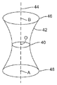
도 7은 레이저 펄스 초점 스팟(40)과 그 근방의 빔 웨이스트의 도면을 도시한다. 빔 웨이스트는, 레이저 펄스(11)가 이동하게 되는 광학 축(44) 상에서 FWHM 방법에 의해 측정된 때의 레이저 펄스(11)의 공간적 에너지 분포의 직경(또는 주 공간축)인 표면(42)에 의해 표현된다. 직경(48)은, 레이저 프로세싱 시스템이 표면(102) 위의 거리 (A-O)에서 레이저 펄스(11)로 초점을 맞출 때 기판(102)의 표면 상에서의 레이저 스팟(15)의 레이저 스팟 사이즈를 나타낸다. 직경(46)은, 레이저 프로세싱 시스템이 표면 아래의 거리(O-B)에서 레이저 펄스(11)로 초점을 맞출 때 기판(102)의 표면 상에서의 레이저 스팟(15)의 레이저 스팟 사이즈를 나타낸다.Fig. 7 shows a view of the laser
다른 또는 추가적인 레이저 또는 상이한 미세기계가공 시스템이 활용될 수 있고 또한 원하는 광학적 표면 특성을 제공하기 위해 상이한 조각, 연마, 및 표면 변형 기술이 활용될 수 있음을 알 수 있을 것이다. 몇몇 대안적인 미세기계가공 시스템, 레이저, 및 프로세스 파라미터는 미국 특허 제8,379,679호, 제8,389,895호, 및 제8,604,380호에서 발견될 수 있으며, 이들은 참조에 의해 본원에 통합된다.It will be appreciated that different or additional lasers or different micromachining systems may be utilized and different sculpting, polishing, and surface modification techniques may be utilized to provide the desired optical surface properties. Several alternative micromachining systems, lasers, and process parameters can be found in U.S. Patent Nos. 8,379,679, 8,389,895, and 8,604,380, which are incorporated herein by reference.
상기 내용은 본 발명의 실시형태의 예시이며 본 발명의 제한으로서 간주되어선 안된다. 본 발명의 몇몇 예시적인 실시형태가 설명되었지만, 본 발명의 신규의 교시와 이점에서 본질적으로 벗어나지 않으면서 예시적인 실시형태에서 많은 변형이 가능함을 당업자는 즉시 알 것이다. 따라서, 이러한 변형 모두는 특허청구범위에서 정의된 바와 같은 본 발명의 범위 내에 포함되도록 의도된다. 그러므로, 상기의 내용은 본 발명의 예시이며 개시된 본 발명의 특정한 예시적인 실시형태에 제한되는 것으로 간주도어선 안되고, 또한 개시된 예시적인 실시형태뿐만 아니라, 다른 실시형태에 대한 변형도 첨부된 특허청구범위의 범위 내에 포함되도록 의도된 것이 이해되어야 한다. 본 발명은 하기의 특허청구범위에 의해 정의되며, 특허청구범위의 균등범위도 본 발명에 포함되어야 한다.The above is an example of embodiments of the present invention and should not be regarded as a limitation of the present invention. Although several exemplary embodiments of the invention have been described, those skilled in the art will readily appreciate that many modifications are possible in the exemplary embodiments without materially departing from the novel teachings and advantages of this invention. Accordingly, all such modifications are intended to be included within the scope of the present invention as defined in the claims. It is therefore to be understood that the foregoing is in no way intended to be considered as limiting the invention to the specific exemplary embodiments of the invention disclosed and that modifications to other embodiments, as well as the disclosed exemplary embodiments, The scope of which is to be understood as being within the scope of the present invention. The invention is defined by the following claims, and equivalents of the claims should be included in the invention.
Claims (23)
상기 외면 아래의 깊이로 상기 기판에 리세스(recess)를 형성하도록 동작가능한 제1의 파라미터 값들을 갖는 제1의 세트의 레이저 프로세싱 파라미터들을 활용하는 단계로서, 상기 기판의 상기 리세스는 제2의 표면 특성을 갖는 오목면을 구비하는, 상기 제1의 세트의 레이저 프로세싱 파라미터들을 활용하는 단계;
상기 제2의 표면 특성과는 상이한 제3의 표면 특성을 갖도록 상기 오목면을 변경하도록 동작가능한 제2의 파라미터 값들을 갖는 제2의 세트의 레이저 프로세싱 파라미터들을 활용하는 단계로서, 상기 제2의 파라미터 값들 중 적어도 하나는 상기 제1의 파라미터 값들 중 대응하는 제1의 파라미터 값과는 상이한, 상기 제2의 세트의 레이저 프로세싱 파라미터들을 활용하는 단계;
상기 제2의 표면 특성 및 상기 제3의 표면 특성과는 상이한 제4의 표면 특성을 갖도록 상기 오목면을 변경하도록 동작가능한 제3의 파라미터 값들을 갖는 제3의 세트의 레이저 프로세싱 파라미터들을 활용하는 단계로서, 상기 제3의 파라미터 값들 중 적어도 하나는 상기 제1의 파라미터 값들 중 대응하는 제1의 파라미터 값과는 상이하고, 상기 제3의 파라미터 값들 중 적어도 하나의 제3의 파라미터 또는 상기 제3의 파라미터 값들 중 다른 제3의 파라미터 값은 상기 제2의 파라미터 값들 중 대응하는 제2의 파라미터 값과는 상이한, 상기 제3의 세트의 레이저 프로세싱 파라미터들을 활용하는 단계를 포함하는, 기판을 프로세싱하기 위한 방법.CLAIMS What is claimed is: 1. A method for processing a substrate with different sets of laser processing parameters to achieve different surface effects on the substrate, the material having an outer surface with a first surface characteristic, the method comprising:
Utilizing a first set of laser processing parameters having first parameter values operable to form a recess in the substrate at a depth below the outer surface, Utilizing the first set of laser processing parameters with a concave surface having surface characteristics;
Utilizing a second set of laser processing parameters having second parameter values operable to change the concave surface to have a third surface characteristic different from the second surface characteristic, Utilizing at least one of the laser processing parameters of the second set, wherein at least one of the values is different from the corresponding first parameter value of the first parameter values;
Utilizing a third set of laser processing parameters having third parameter values operable to change the concave surface to have a fourth surface characteristic different from the second surface characteristic and the third surface characteristic, Wherein at least one of the third parameter values is different from a corresponding first parameter value of the first parameter values and at least one third parameter of the third parameter values or the third parameter value of the third parameter values And utilizing a third set of laser processing parameters, wherein another third parameter value of the parameter values is different from a corresponding second parameter value of the second parameter values. Way.
상기 제1의 세트의 레이저 프로세싱 파라미터들은 조각 프로세스(engraving process)를 수행하기에 적합하고, 상기 제2의 세트의 레이저 프로세싱 파라미터들은 상기 오목면의 부분들을 연마하기 위한 연마 프로세스를 수행하기에 적합한, 기판을 프로세싱하기 위한 방법.The method according to claim 1,
Wherein the first set of laser processing parameters are adapted to perform an engraving process and the second set of laser processing parameters are adapted to perform a polishing process for polishing portions of the concave surface, A method for processing a substrate.
상기 제3의 세트의 레이저 프로세싱 파라미터들은 상기 오목면의 부분들을 어둡게 하기 위한 암화 프로세스를 수행하기에 적합한, 기판을 프로세싱하기 위한 방법.The method according to claim 1,
Wherein the third set of laser processing parameters are suitable for performing a darkening process to darken portions of the concave surface.
상기 제3의 세트의 레이저 프로세싱 파라미터들은 상기 오목면의 부분들을 크로스 해칭(cross-hatching)하기 위한 크로스 해칭 프로세스를 수행하기에 적합한, 기판을 프로세싱하기 위한 방법.The method according to claim 1,
Said third set of laser processing parameters being suitable for performing a cross hatching process for cross-hatching portions of said concave surface.
상기 제3의 세트의 레이저 프로세싱 파라미터들은 상기 오목면에 오목부들을 펀칭하기 위한 펀칭 프로세스를 수행하기에 적합한, 기판을 프로세싱하기 위한 방법.The method according to claim 1,
Wherein the third set of laser processing parameters are suitable for performing a punching process to punch the recesses in the concave surface.
상기 제1 및 제2의 세트의 레이저 프로세싱 파라미터들은 파장 값들 또는 스팟 사이즈 값들 중 상이한 값들을 갖는, 기판을 프로세싱하기 위한 방법.The method according to claim 1,
Wherein the first and second sets of laser processing parameters have different ones of the wavelength values or spot size values.
상기 제1 및 제3의 세트의 레이저 프로세싱 파라미터들은 펄스폭 값들 또는 스팟 사이즈 값들 중 상이한 값들을 갖는, 기판을 프로세싱하기 위한 방법.The method according to claim 1,
Wherein the first and third sets of laser processing parameters have different ones of pulse width values or spot size values.
상기 제1 및 제3의 세트의 레이저 프로세싱 파라미터들은 반복률 값들 또는 스팟 사이즈 값들 중 상이한 값들을 갖는, 기판을 프로세싱하기 위한 방법.The method according to claim 1,
Wherein the first and third sets of laser processing parameters have different ones of the repetition rate values or spot size values.
상기 제2 및 제3의 세트의 레이저 프로세싱 파라미터들은 주사 속도 값들 또는 스팟 사이즈 값들 중 상이한 값들을 갖는, 기판을 프로세싱하기 위한 방법.The method according to claim 1,
And wherein the second and third sets of laser processing parameters have different values of scan speed values or spot size values.
상기 제1의 파라미터 값들은 약 25㎛와 약 100㎛ 사이의 주 공간축을 갖는 스팟 사이즈, 적외선 파장, 약 10㎱와 약 100㎱ 사이의 펄스폭, 및 약 100㎑와 약 200㎑ 사이의 펄스 반복률 중 적어도 2개를 포함하는, 기판을 프로세싱하기 위한 방법.The method according to claim 1,
Wherein the first parameter values are selected from the group consisting of a spot size having a main spatial axis between about 25 microns and about 100 microns, an infrared wavelength, a pulse width between about 10 kV and about 100 kV, and a pulse repetition rate between about 100 kHz and about 200 kHz ≪ / RTI > wherein at least two of the at least two of the plurality of substrates are processed.
상기 제2의 파라미터 값들은 약 10㎛와 약 50㎛ 사이의 주 공간축을 갖는 스팟 사이즈, 가시 파장, 약 10㎱와 약 100㎱ 사이의 펄스폭, 약 100㎑보다 더 큰 펄스 반복률, 및 약 500μJ에서 약 1000μJ 사이의 펄스 에너지 중 적어도 2개를 포함하는, 기판을 프로세싱하기 위한 방법.The method according to claim 1,
Wherein the second parameter values are selected from the group consisting of a spot size having a major spatial axis between about 10 and about 50 microns, a visible wavelength, a pulse width between about 10 and about 100 nanometers, a pulse repetition rate greater than about 100 kHz, To about < RTI ID = 0.0 > 1000J. ≪ / RTI >
상기 제3의 파라미터 값들은 약 50㎛보다 더 짧은 주 공간축을 갖는 스팟 사이즈, 약 500fs와 약 50㎰ 사이의 펄스폭, 및 약 50㎜/초보다 더 느린 주사 속도 중 적어도 2개를 포함하는, 기판을 프로세싱하기 위한 방법.The method according to claim 1,
Wherein the third parameter values comprise at least two of a spot size having a minor spatial axis of less than about 50 [mu] m, a pulse width of between about 500 fs and about 50 fs, and a scan rate of less than about 50 mm / A method for processing a substrate.
상기 제3의 파라미터 값들은 약 50㎛와 약 100㎛ 사이의 주 공간축을 갖는 스팟 사이즈, 1000㎚보다 더 짧은 파장, 약 1 내지 5와트 사이의 평균 파워, 및 약 70㎜/초보다 더 빠른 주사 속도 중 적어도 2개를 포함하는, 기판을 프로세싱하기 위한 방법.The method according to claim 1,
The third parameter values may include a spot size having a major spatial axis between about 50 탆 and about 100 탆, a wavelength shorter than 1000 nm, an average power between about 1 and 5 watts, and a scan greater than about 70 mm / Speed of the substrate. ≪ Desc / Clms Page number 17 >
상기 제3의 파라미터 값들은 적외선 파장, 약 3 내지 10와트 사이의 평균 파워, 및 약 75㎑와 약 125㎑ 사이의 펄스 반복률 중 적어도 2개를 포함하는, 기판을 프로세싱하기 위한 방법.The method according to claim 1,
Wherein the third parameter values comprise at least two of an infrared wavelength, an average power between about 3 and 10 watts, and a pulse repetition rate between about 75 kHz and about 125 kHz.
상기 제2의 세트의 레이저 펄스들은 상기 오목면 상에 레이저 스팟들을 형성하고 후속 레이저 스팟이 선행 레이저 스팟을 75% 내지 95%만큼 중첩하도록 지향되는, 기판을 프로세싱하기 위한 방법.The method according to claim 1,
Wherein the second set of laser pulses forms laser spots on the concave surface and the subsequent laser spot is oriented to overlap the preceding laser spot by 75% to 95%.
상기 제2의 세트의 레이저 펄스들은 반사성 또는 연마된 표면을 생성하는, 기판을 프로세싱하기 위한 방법.The method according to claim 1,
Wherein the second set of laser pulses produce a reflective or polished surface.
상기 제3의 세트의 레이저 펄스들은 상기 오목면에 광을 흡수하도록 구조화된 주기적 구조체들을 생성하는, 기판을 프로세싱하기 위한 방법.The method according to claim 1,
Wherein the third set of laser pulses generate structured periodic structures to absorb light at the concave surface.
상기 제3의 세트의 레이저 펄스들은 상기 오목면에 비중첩 크레이터들(craters)의 패턴을 형성하는, 기판을 프로세싱하기 위한 방법.The method according to claim 1,
Wherein the third set of laser pulses forms a pattern of non-overlapping craters on the concave surface.
상기 외면 아래의 깊이로 상기 기판에 리세스를 형성함으로써 상기 기판을 조각하도록 동작가능한 제1의 파라미터 값들을 갖는 제1의 세트의 레이저 프로세싱 파라미터들을 활용하는 단계로서, 상기 기판의 상기 리세스는 제2의 표면 특성을 갖는 오목면을 구비하는, 상기 제1의 세트의 레이저 프로세싱 파라미터들을 활용하는 단계;
상기 제2의 표면 특성과는 상이한 제3의 표면 특성을 갖도록 상기 오목면을 연마하도록 동작가능한 제2의 파라미터 값들을 갖는 제2의 세트의 레이저 프로세싱 파라미터들을 활용하는 단계로서, 상기 제2의 파라미터 값들 중 적어도 하나는 상기 제1의 파라미터 값들 중 대응하는 제1의 파라미터 값과는 상이한, 상기 제2의 세트의 레이저 프로세싱 파라미터들을 활용하는 단계;
상기 제2의 표면 특성 및 상기 제3의 표면 특성과는 상이한 제4의 표면 특성을 갖도록 상기 오목면을 변형하도록 동작가능한 제3의 파라미터 값들을 갖는 제3의 세트의 레이저 프로세싱 파라미터들을 활용하는 단계로서, 상기 제3의 파라미터 값들 중 적어도 하나는 상기 제1의 파라미터 값들 중 대응하는 제1의 파라미터와는 상이하고, 상기 제3의 파라미터 값들 중 적어도 하나의 제3의 파라미터 값 또는 상기 제3의 파라미터 값들 중 다른 제3의 파라미터 값은 상기 제2의 파라미터 값들 중 대응하는 제2의 파라미터 값과는 상이한, 상기 제3의 세트의 레이저 프로세싱 파라미터들을 활용하는 단계를 포함하는, 기판을 프로세싱하기 위한 방법.A method for processing a substrate with different sets of laser processing parameters to achieve different surface effects on the substrate, the material having an outer surface with a first surface characteristic, the method comprising:
Utilizing a first set of laser processing parameters having first parameter values operable to engage said substrate by forming a recess in said substrate at a depth below said outer surface, Utilizing a first set of laser processing parameters comprising a concave surface having surface characteristics of 2;
Utilizing a second set of laser processing parameters having second parameter values operable to polish the concave surface to have a third surface characteristic different from the second surface characteristic, Utilizing at least one of the laser processing parameters of the second set, wherein at least one of the values is different from the corresponding first parameter value of the first parameter values;
Utilizing a third set of laser processing parameters having third parameter values operable to deform the concave surface to have a fourth surface characteristic different from the second surface characteristic and the third surface characteristic, Wherein at least one of the third parameter values is different from a corresponding first parameter of the first parameter values and at least one third parameter value of the third parameter values or the third parameter value of the third parameter values And utilizing a third set of laser processing parameters, wherein another third parameter value of the parameter values is different from a corresponding second parameter value of the second parameter values. Way.
상기 외면 아래의 깊이로 상기 기판에 리세스를 형성하도록 동작가능한 제1의 파라미터 값들을 갖는 제1의 세트의 레이저 프로세싱 파라미터들을 제공하도록 구성된 제1의 레이저로서, 상기 기판의 상기 리세스는 제2의 표면 특성을 갖는 오목면을 구비하는, 상기 제1의 레이저;
상기 제2의 표면 특성과는 상이한 제3의 표면 특성을 갖도록 상기 오목면을 변경하도록 동작가능한 제2의 파라미터 값들을 갖는 제2의 세트의 레이저 프로세싱 파라미터들을 제공하도록 구성된 제2의 레이저로서, 상기 제2의 파라미터 값들 중 적어도 하나는 상기 제1의 파라미터 값들 중 대응하는 제1의 파라미터 값과는 상이하고, 상기 제2의 레이저는 상기 제1의 레이저이거나 또는 상이한 레이저인, 상기 제 2의 레이저; 및
상기 제2의 표면 특성 및 상기 제3의 표면 특성과는 상이한 제4의 표면 특성을 갖도록 상기 오목면을 변경하도록 동작가능한 제3의 파라미터 값들을 갖는 제3의 세트의 레이저 프로세싱 파라미터들을 제공하도록 구성된 제3의 레이저로서, 상기 제3의 파라미터 값들 중 적어도 하나는 상기 제1의 파라미터 값들 중 대응하는 제1의 파라미터 값과는 상이하고, 상기 제3의 파라미터 값들 중 적어도 하나의 제3의 파라미터 값 또는 상기 제3의 파라미터 값들 중 다른 제3의 파라미터 값은 상기 제2의 파라미터 값들 중 대응하는 제2의 파라미터 값과는 상이하고, 상기 제3의 레이저는 상기 제1 또는 제2의 레이저이거나 또는 상이한 레이저인, 상기 제3의 레이저를 포함하는, 기판을 프로세싱하기 위한 레이저 시스템.CLAIMS What is claimed is: 1. A laser system for processing a substrate with different sets of laser processing parameters to achieve different surface effects on the substrate, the material having an outer surface with a first surface characteristic, the system comprising:
A first laser configured to provide a first set of laser processing parameters having first parameter values operable to form a recess in the substrate at a depth below the outer surface, Said first laser having a concave surface having surface characteristics of said first laser;
A second laser configured to provide a second set of laser processing parameters having second parameter values operable to change the concave surface to have a third surface characteristic different from the second surface characteristic, Wherein at least one of the second parameter values is different from the corresponding one of the first parameter values and the second laser is the first laser or a different laser, ; And
And to provide a third set of laser processing parameters having third parameter values operable to change the concave surface to have a fourth surface characteristic different from the second surface characteristic and the third surface characteristic At least one of the third parameter values being different from a corresponding first parameter value of the first parameter values, and at least one third parameter value of the third parameter values Or the third parameter value of the third parameter values is different from the corresponding second parameter value of the second parameter values and the third laser is the first or second laser, Wherein the third laser is a different laser. ≪ Desc / Clms Page number 19 >
제1의 광 흡수 레벨을 나타내는 오목한 알루미늄 표면을 제공하기 위해 알루미늄 표면에 리세스를 형성하는 단계; 및
약 15㎜/sec와 약 35㎜/sec 사이의 범위 내의 주사 속도에서 그리고 약 5㎛와 약 15㎛ 사이의 범위 내의 연속 주사들 사이의 피치에서 상기 오목한 알루미늄 표면의 영역들을 프로세싱하기 위해 레이저 출력의 적용에 의해 상기 오목한 알루미늄 표면을 변형하는 단계로서, 상기 레이저 출력은 약 1㎰에서 약 10㎱까지의 범위 내의 펄스 지속시간과 약 1㎛와 약 30㎛ 사이의 범위 내의 레이저 스팟 직경을 갖는 레이저 펄스들을 포함하고, 상기 레이저 출력의 적용은 상기 오목한 알루미늄 표면의 프로세싱된 영역들을 상기 제1의 광흡수 레벨보다 더 높은 제2의 광흡수 레벨을 나타내게 하고, 이에 의해 상기 오목한 알루미늄 표면의 상기 프로세싱된 영역들이 상기 오목한 알루미늄 표면의 상기 프로세싱된 영역들을 보는 사람 눈에 검게 보이게 되는, 상기 오목한 알루미늄 표면을 변형하는 단계를 포함하는, 알루미늄 표면의 외관을 변형하는 방법.A method of modifying the appearance of an aluminum surface comprising:
Forming a recess in the aluminum surface to provide a concave aluminum surface indicative of a first level of light absorption; And
At a scanning speed in a range between about 15 mm / sec and about 35 mm / sec and at pitches between successive scans in a range between about 5 and about 15 micrometers, to process the areas of the concave aluminum surface The laser output having a pulse duration in a range from about 1 kPa to about 10 kPa and a laser pulse having a laser spot diameter in a range between about 1 [mu] m and about 30 [mu] m, Wherein the application of the laser output causes the processed regions of the concave aluminum surface to exhibit a second light absorption level that is higher than the first light absorption level thereby causing the processed region of the concave aluminum surface Are blackened in the eye of the person viewing said processed areas of said concave aluminum surface Method of modifying the appearance of the aluminum surface which comprises the step of modifying the aluminum surface.
제1의 표면 외관을 나타내는 오목한 알루미늄 표면을 제공하기 위해 알루미늄 표면에 리세스를 형성하는 단계; 및
약 60㎜/sec와 약 80㎜/sec 사이의 범위 내의 주사 속도에서 그리고 약 10㎛와 약 20㎛ 사이의 범위 내의 연속 주사들 사이의 피치에서 상기 오목한 알루미늄 표면의 영역들을 프로세싱하기 위해 레이저 출력의 적용에 의해 상기 오목한 알루미늄 표면을 변형하는 단계로서, 상기 레이저 출력은 녹색 레이저 파장, 약 50㎛와 약 100㎛ 사이의 범위 내의 레이저 스팟 직경, 및 약 3W에서 약 6W까지의 범위 내의 파워를 갖는 레이저 펄스들을 포함하고, 상기 레이저 출력의 적용은 상기 오목한 알루미늄 표면의 프로세싱된 영역들을 상기 제1의 표면 외관보다 더 하얗게 보이는 제2의 표면 외관을 나타내게 하고, 이에 의해 상기 오목한 알루미늄 표면의 상기 프로세싱된 영역들이 상기 오목한 알루미늄 표면의 상기 프로세싱된 영역들을 보는 사람 눈에는 하얗게 보이게 되는, 상기 오목한 알루미늄 표면을 변형하는 단계를 포함하는, 알루미늄 표면의 외관을 변형하는 방법.A method of modifying the appearance of an aluminum surface comprising:
Forming a recess in the aluminum surface to provide a concave aluminum surface exhibiting a first surface appearance; And
At a scanning speed in a range between about 60 mm / sec and about 80 mm / sec and at pitches between successive scans in a range between about 10 and about 20 micrometers, to process the areas of the concave aluminum surface Wherein the laser output is a laser having a green laser wavelength, a laser spot diameter in a range between about 50 [mu] m and about 100 [mu] m, and a power within a range of about 3 W to about 6 W Wherein the application of the laser output causes the processed regions of the concave aluminum surface to exhibit a second surface appearance that appears to be whiter than the first surface appearance so that the processed region of the concave aluminum surface Lt; RTI ID = 0.0 > of the concave aluminum surface That is, how to modify the appearance of the aluminum surface which comprises the step of deforming the concave surface of aluminum.
제1의 표면 외관을 나타내는 오목한 알루미늄 표면을 제공하기 위해 알루미늄 표면에 리세스를 형성하는 단계; 및
약 50㎑에서 약 500㎑까지의 범위 내의 펄스 반복률에서 약 30 내지 70개의 레이저 펄스들로 상기 오목한 알루미늄 표면의 별개의 영역들을 프로세싱하여 약 30㎛에서 약 60㎛까지의 범위 내의 인접한 리세스들 사이의 중심 대 중심 간격만큼 분리되고 약 5㎛에서 약 15㎛까지의 범위 내의 깊이를 갖는 별개의 리세스들을 형성하기 위해 레이저 출력의 적용에 의해 상기 오목한 알루미늄 표면을 변형하는 단계로서, 상기 레이저 출력은 적외선 레이저 파장, 약 15㎛와 약 40㎛ 사이의 범위 내의 레이저 스팟 직경, 및 약 1W에서 약 10W까지의 범위 내의 파워를 갖는 레이저 펄스들을 포함하고, 상기 레이저 출력의 적용은 상기 오목한 알루미늄 표면의 프로세싱된 영역들을 상기 제1의 표면 외관보다 더 하얗게 보이는 제2의 표면 외관을 나타내게 하고, 이에 의해 상기 오목한 알루미늄 표면의 상기 프로세싱된 영역들이 상기 오목한 알루미늄 표면의 상기 프로세싱된 영역들을 보는 사람 눈에는 하얗게 보이게 되는, 상기 오목한 알루미늄 표면을 변형하는 단계를 포함하는, 알루미늄 표면의 외관을 변형하는 방법.As a method of deforming the appearance of the aluminum surface,
Forming a recess in the aluminum surface to provide a concave aluminum surface exhibiting a first surface appearance; And
Processing the distinct areas of the concave aluminum surface with about 30 to 70 laser pulses at a pulse repetition rate in the range of about 50 kHz to about 500 kHz to produce an image of an area between adjacent recesses in the range of about 30 microns to about 60 microns Deformation of said concave aluminum surface by application of a laser output to form discrete recesses separated by a center-to-center spacing of said recesses and having a depth in a range from about 5 탆 to about 15 탆, The laser pulse having an infrared laser wavelength, a laser spot diameter in a range between about 15 microns and about 40 microns, and a power in a range from about 1 W to about 10 W. The application of the laser power is performed by processing the concave aluminum surface Of the first surface appearance to show a second surface appearance that is whiter than the first surface appearance, Method of modifying the appearance of the processed areas are seen as the processed area of the concave surface of aluminum human eye, comprising white and looked like, deforming the concave surface of aluminum, the aluminum surface of the concave surface of aluminum.
Applications Claiming Priority (3)
| Application Number | Priority Date | Filing Date | Title |
|---|---|---|---|
| US201261740430P | 2012-12-20 | 2012-12-20 | |
| US61/740,430 | 2012-12-20 | ||
| PCT/US2013/076677 WO2014100469A1 (en) | 2012-12-20 | 2013-12-19 | Methods of forming images by laser micromachining |
Publications (1)
| Publication Number | Publication Date |
|---|---|
| KR20150097475A true KR20150097475A (en) | 2015-08-26 |
Family
ID=50973462
Family Applications (1)
| Application Number | Title | Priority Date | Filing Date |
|---|---|---|---|
| KR1020157013490A KR20150097475A (en) | 2012-12-20 | 2013-12-19 | Methods of forming images by laser micromachining |
Country Status (6)
| Country | Link |
|---|---|
| US (1) | US20140175067A1 (en) |
| JP (1) | JP6318171B2 (en) |
| KR (1) | KR20150097475A (en) |
| CN (1) | CN104884205A (en) |
| TW (1) | TWI604909B (en) |
| WO (1) | WO2014100469A1 (en) |
Cited By (1)
| Publication number | Priority date | Publication date | Assignee | Title |
|---|---|---|---|---|
| KR102254339B1 (en) * | 2021-02-03 | 2021-05-21 | 주식회사 21세기 | Precision surface planing-polishing apparatus femtosecond pulse laser and a method thereof |
Families Citing this family (13)
| Publication number | Priority date | Publication date | Assignee | Title |
|---|---|---|---|---|
| WO2016117224A1 (en) * | 2015-01-20 | 2016-07-28 | 東レエンジニアリング株式会社 | Marking device and method, pattern generation device, and workpiece |
| EP3047932B1 (en) * | 2015-01-21 | 2018-12-26 | Agie Charmilles New Technologies SA | Method of laser ablation for engraving of a surface with patch optimization, with corresponding software and machine tool |
| DE102015007216B4 (en) * | 2015-06-03 | 2023-07-20 | Asml Netherlands B.V. | Method for producing a holding plate, in particular for a clamp for holding wafers, method for producing a holding device for holding a component, holding plate and holding device |
| WO2016207660A1 (en) | 2015-06-24 | 2016-12-29 | University Of Dundee | Method of, and apparatus for, reducing photoelectron yield and/or secondary electron yield |
| GB201603991D0 (en) | 2016-03-08 | 2016-04-20 | Univ Dundee | Processing method and apparatus |
| WO2017034533A1 (en) * | 2015-08-22 | 2017-03-02 | Tokyo Electron Limited | Substrate backside texturing |
| AT519177B1 (en) * | 2016-10-06 | 2019-04-15 | Trotec Laser Gmbh | Method for engraving, marking and / or inscribing a workpiece with |
| DE102017202269A1 (en) * | 2017-02-13 | 2018-08-16 | Sauer Gmbh | PROCESS FOR MACHINING A WORKPIECE SURFACE BY MEANS OF A LASER |
| JP6722617B2 (en) * | 2017-05-12 | 2020-07-15 | 三菱電線工業株式会社 | Metal surface roughening method |
| KR102630873B1 (en) * | 2019-05-03 | 2024-01-31 | 삼성디스플레이 주식회사 | Manufacturing method for the window |
| EP4046817B1 (en) * | 2021-02-23 | 2024-01-03 | DM Surfaces SA | Method for laser treatment of a timepiece component intended to darken at least one portion |
| US11784130B2 (en) * | 2021-08-27 | 2023-10-10 | Taiwan Semiconductor Manufacturing Company, Ltd. | Structure and formation method of package with underfill |
| CN115819121B (en) * | 2022-12-15 | 2023-11-07 | 潮州三环(集团)股份有限公司 | Surface matte treatment method for zirconia ceramic and zirconia ceramic cover plate |
Family Cites Families (26)
| Publication number | Priority date | Publication date | Assignee | Title |
|---|---|---|---|---|
| US5126532A (en) * | 1989-01-10 | 1992-06-30 | Canon Kabushiki Kaisha | Apparatus and method of boring using laser |
| FI92112C (en) * | 1992-11-09 | 1994-09-26 | Partek Cargotec Oy | Method of designing on a glossy metal surface differs from darker from its background and a thus colored areas exhibiting metal surface |
| US5461212A (en) * | 1993-06-04 | 1995-10-24 | Summit Technology, Inc. | Astigmatic laser ablation of surfaces |
| US5841099A (en) * | 1994-07-18 | 1998-11-24 | Electro Scientific Industries, Inc. | Method employing UV laser pulses of varied energy density to form depthwise self-limiting blind vias in multilayered targets |
| JP2001510109A (en) * | 1997-07-16 | 2001-07-31 | オーチス エレベータ カンパニー | Methods and compositions for laser imprinting and articles imprinted using the methods and the compositions |
| JPH11207477A (en) * | 1998-01-26 | 1999-08-03 | Mitsubishi Electric Corp | Scraping device and scraping method |
| JP4465065B2 (en) * | 1998-10-30 | 2010-05-19 | シャープ株式会社 | Wiring disconnection repair method |
| IES20010949A2 (en) * | 2000-10-26 | 2002-07-10 | Xsil Technology Ltd | Control of laser machining |
| US6864459B2 (en) * | 2001-02-08 | 2005-03-08 | The Regents Of The University Of California | High precision, rapid laser hole drilling |
| US7357486B2 (en) * | 2001-12-20 | 2008-04-15 | Hewlett-Packard Development Company, L.P. | Method of laser machining a fluid slot |
| US20050087522A1 (en) * | 2003-10-24 | 2005-04-28 | Yunlong Sun | Laser processing of a locally heated target material |
| US7486705B2 (en) * | 2004-03-31 | 2009-02-03 | Imra America, Inc. | Femtosecond laser processing system with process parameters, controls and feedback |
| US20060000814A1 (en) * | 2004-06-30 | 2006-01-05 | Bo Gu | Laser-based method and system for processing targeted surface material and article produced thereby |
| US20070235902A1 (en) * | 2006-03-31 | 2007-10-11 | 3M Innovative Properties Company | Microstructured tool and method of making same using laser ablation |
| JP4910100B2 (en) * | 2006-07-06 | 2012-04-04 | 日本ケミコン株式会社 | Metal case for electronic components |
| US10876193B2 (en) * | 2006-09-29 | 2020-12-29 | University Of Rochester | Nanostructured materials, methods, and applications |
| GB2444037A (en) * | 2006-11-27 | 2008-05-28 | Xsil Technology Ltd | Laser Machining |
| US8710402B2 (en) * | 2007-06-01 | 2014-04-29 | Electro Scientific Industries, Inc. | Method of and apparatus for laser drilling holes with improved taper |
| WO2009050938A1 (en) * | 2007-10-16 | 2009-04-23 | Mitsuboshi Diamond Industrial Co., Ltd. | Method of machining u-shaped groove of substrate of fragile material, removal method, boring method and chamfering method using the same method |
| GB0804955D0 (en) * | 2008-03-18 | 2008-04-16 | Rumsby Philip T | Method and apparatus for laser processing the surface of a drum |
| JP5454080B2 (en) * | 2008-10-23 | 2014-03-26 | 住友電気工業株式会社 | Laser processing method and laser processing apparatus |
| JP4612733B2 (en) * | 2008-12-24 | 2011-01-12 | 東芝機械株式会社 | Pulse laser processing equipment |
| JP5473414B2 (en) * | 2009-06-10 | 2014-04-16 | 株式会社ディスコ | Laser processing equipment |
| US8389895B2 (en) * | 2010-06-25 | 2013-03-05 | Electro Scientifix Industries, Inc. | Method and apparatus for reliably laser marking articles |
| JP2012183549A (en) * | 2011-03-04 | 2012-09-27 | Mitsubishi Electric Corp | METHOD OF MARKING SiC SEMICONDUCTOR WAFER AND SiC SEMICONDUCTOR WAFER |
| CN103442839B (en) * | 2011-03-30 | 2015-12-23 | 日本碍子株式会社 | To the labeling method of hardware |
-
2013
- 2013-12-19 US US14/135,097 patent/US20140175067A1/en not_active Abandoned
- 2013-12-19 CN CN201380058957.5A patent/CN104884205A/en active Pending
- 2013-12-19 KR KR1020157013490A patent/KR20150097475A/en not_active Application Discontinuation
- 2013-12-19 JP JP2015549732A patent/JP6318171B2/en active Active
- 2013-12-19 WO PCT/US2013/076677 patent/WO2014100469A1/en active Application Filing
- 2013-12-20 TW TW102147344A patent/TWI604909B/en not_active IP Right Cessation
Cited By (2)
| Publication number | Priority date | Publication date | Assignee | Title |
|---|---|---|---|---|
| KR102254339B1 (en) * | 2021-02-03 | 2021-05-21 | 주식회사 21세기 | Precision surface planing-polishing apparatus femtosecond pulse laser and a method thereof |
| WO2022169032A1 (en) * | 2021-02-03 | 2022-08-11 | 주식회사 21세기 | Planing-polishing apparatus and method using femtosecond pulse laser |
Also Published As
| Publication number | Publication date |
|---|---|
| CN104884205A (en) | 2015-09-02 |
| TWI604909B (en) | 2017-11-11 |
| JP2016505390A (en) | 2016-02-25 |
| TW201433396A (en) | 2014-09-01 |
| JP6318171B2 (en) | 2018-04-25 |
| WO2014100469A8 (en) | 2014-12-31 |
| WO2014100469A1 (en) | 2014-06-26 |
| US20140175067A1 (en) | 2014-06-26 |
Similar Documents
| Publication | Publication Date | Title |
|---|---|---|
| KR20150097475A (en) | Methods of forming images by laser micromachining | |
| Knowles et al. | Micro-machining of metals, ceramics and polymers using nanosecond lasers | |
| US10112263B2 (en) | Method and apparatus for reliably laser marking articles | |
| US7469831B2 (en) | Laser-based method and system for processing targeted surface material and article produced thereby | |
| KR101869435B1 (en) | Method and apparatus for reliably laser marking articles | |
| EP3313605B1 (en) | Method of laser blackening of a surface, wherein the laser has a specific power density and a specific pulse duration | |
| US20150158116A1 (en) | Method and apparatus for internally marking a substrate having a rough surface | |
| EP3511106B1 (en) | Laser based machining of glass material | |
| EP2704872B1 (en) | Laser-based marking method and apparatus | |
| Wlodarczyk et al. | Investigation of an interlaced laser beam scanning method for ultrashort pulse laser micromachining applications | |
| JP2007229778A (en) | Marking method and apparatus | |
| EP4003636B1 (en) | Method for the removal of a coating from a metal substrate by laser ablation | |
| JP2005034865A (en) | Apparatus and method for working roll | |
| Semaltianos et al. | Picosecond laser ablation of nickel-based superalloy C263 | |
| Neuenschwander et al. | High throughput surface structuring with ultrashort pulses in synchronized mode with fast polygon line scanner | |
| JP5305928B2 (en) | How to create a periodic structure | |
| US20180257170A1 (en) | Controlled separation of laser processed brittle material | |
| JP2005101305A (en) | Inorganic nitride component and marking method therefor | |
| TW201446378A (en) | Laser processing using an astigmatic elongated beam spot and using ultrashort pulses and/or longer wavelengths | |
| KR101425190B1 (en) | Method of patterning micro structure on metal mold using laser ablation | |
| EP3481583B1 (en) | Method and system of ultrafast laser writing of highly-regular periodic structures | |
| JP2004188437A (en) | Method for machining fine inclined face | |
| Bovatsek et al. | High-power, nanosecond-pulse Q-switch laser technology with flattop beam-shaping technique for efficient industrial laser processing | |
| Alesenkov | Micromachining of nontransparent materials inair and water with femtosecond laser pulses | |
| Gerke et al. | Patterning and marking of textured and untextured silicon solar cells using a 532 nm picosecond fiber laser |
Legal Events
| Date | Code | Title | Description |
|---|---|---|---|
| WITN | Application deemed withdrawn, e.g. because no request for examination was filed or no examination fee was paid |