KR20150087020A - Apparatus and method of measuring bio impedence - Google Patents
Apparatus and method of measuring bio impedence Download PDFInfo
- Publication number
- KR20150087020A KR20150087020A KR1020140007377A KR20140007377A KR20150087020A KR 20150087020 A KR20150087020 A KR 20150087020A KR 1020140007377 A KR1020140007377 A KR 1020140007377A KR 20140007377 A KR20140007377 A KR 20140007377A KR 20150087020 A KR20150087020 A KR 20150087020A
- Authority
- KR
- South Korea
- Prior art keywords
- frequency
- signal
- voltage
- bioimpedance
- unit
- Prior art date
Links
Images


Classifications
-
- A—HUMAN NECESSITIES
- A61—MEDICAL OR VETERINARY SCIENCE; HYGIENE
- A61B—DIAGNOSIS; SURGERY; IDENTIFICATION
- A61B5/00—Measuring for diagnostic purposes; Identification of persons
- A61B5/02—Detecting, measuring or recording pulse, heart rate, blood pressure or blood flow; Combined pulse/heart-rate/blood pressure determination; Evaluating a cardiovascular condition not otherwise provided for, e.g. using combinations of techniques provided for in this group with electrocardiography or electroauscultation; Heart catheters for measuring blood pressure
- A61B5/026—Measuring blood flow
-
- A—HUMAN NECESSITIES
- A61—MEDICAL OR VETERINARY SCIENCE; HYGIENE
- A61B—DIAGNOSIS; SURGERY; IDENTIFICATION
- A61B5/00—Measuring for diagnostic purposes; Identification of persons
- A61B5/05—Detecting, measuring or recording for diagnosis by means of electric currents or magnetic fields; Measuring using microwaves or radio waves
- A61B5/053—Measuring electrical impedance or conductance of a portion of the body
- A61B5/0531—Measuring skin impedance
-
- A—HUMAN NECESSITIES
- A61—MEDICAL OR VETERINARY SCIENCE; HYGIENE
- A61B—DIAGNOSIS; SURGERY; IDENTIFICATION
- A61B5/00—Measuring for diagnostic purposes; Identification of persons
- A61B5/05—Detecting, measuring or recording for diagnosis by means of electric currents or magnetic fields; Measuring using microwaves or radio waves
- A61B5/053—Measuring electrical impedance or conductance of a portion of the body
- A61B5/0537—Measuring body composition by impedance, e.g. tissue hydration or fat content
-
- A—HUMAN NECESSITIES
- A61—MEDICAL OR VETERINARY SCIENCE; HYGIENE
- A61B—DIAGNOSIS; SURGERY; IDENTIFICATION
- A61B5/00—Measuring for diagnostic purposes; Identification of persons
- A61B5/08—Detecting, measuring or recording devices for evaluating the respiratory organs
- A61B5/0809—Detecting, measuring or recording devices for evaluating the respiratory organs by impedance pneumography
-
- A—HUMAN NECESSITIES
- A61—MEDICAL OR VETERINARY SCIENCE; HYGIENE
- A61B—DIAGNOSIS; SURGERY; IDENTIFICATION
- A61B5/00—Measuring for diagnostic purposes; Identification of persons
- A61B5/72—Signal processing specially adapted for physiological signals or for diagnostic purposes
- A61B5/7228—Signal modulation applied to the input signal sent to patient or subject; demodulation to recover the physiological signal
Abstract
Description
아래 실시예들은 생체 임피던스 측정 장치 및 방법에 관한 것이다.
The following embodiments relate to an apparatus and a method for measuring bioimpedance.
환자의 건강 상태를 진단하기 위한 다양한 의료 장비들이 개발 중에 있다. 건강 진단 과정에서 환자의 편의, 건강 진단 결과의 신속성 등으로 인하여 환자의 전기적인 생체 신호를 측정하기 위한 의료 장비들의 중요성이 부각되고 있다.A variety of medical devices are being developed to diagnose patients' health conditions. The importance of medical devices for measuring electrical bio-signals of patients due to the convenience of patients and the promptness of the results of medical checkups in the medical examination process has been emphasized.
생체 임피던스는 생체의 건강이나 감정 상태를 모니터링하기 위하여 이용될 수 있다.
The bioimpedance can be used to monitor the health or emotional state of the living body.
일 측에 따른 생체 임피던스 측정 장치는 제1 주파수의 전류를 출력하는 전류 인가부; 제2 주파수를 이용하여, 상기 전류가 생체를 통해 흐름으로써 발생되는 전압을 변조하는 중간 변조부; 변조된 전압을 증폭하는 증폭부; 및 제3 주파수를 이용하여, 증폭된 전압을 복조하는 복조부를 포함한다.An apparatus for measuring bio-impedance according to one side includes: a current applying unit for outputting a current of a first frequency; An intermediate modulator for modulating a voltage generated by flowing the current through the living body using a second frequency; An amplifier for amplifying the modulated voltage; And a demodulator for demodulating the amplified voltage using the third frequency.
이 때, 상기 제3 주파수는 상기 제1 주파수와 상기 제2 주파수 사이의 차이에 해당할 수 있다. At this time, the third frequency may correspond to the difference between the first frequency and the second frequency.
또한, 상기 제3 주파수는 상기 증폭부의 대역폭에 의해 결정될 수 있다. 또한, 상기 제2 주파수는 상기 제1 주파수에서 상기 제2 주파수를 차감한 값에 해당하는 주파수가 상기 증폭부의 대역폭에 포함되도록 결정될 수 있다.The third frequency may be determined by the bandwidth of the amplification unit. Also, the second frequency may be determined such that a frequency corresponding to a value obtained by subtracting the second frequency from the first frequency is included in the bandwidth of the amplification unit.
또한, 상기 제1 주파수는 측정하려는 생체 임피던스의 유형에 대응될 수 있다.Also, the first frequency may correspond to the type of the bioimpedance to be measured.
또한, 상기 증폭부는 상기 변조된 전압의 주파수 대역 중 상기 제1 주파수에서 상기 제2 주파수를 차감한 값에 해당하는 주파수 이하 대역의 신호를 증폭할 수 있다.The amplifying unit may amplify a signal of a sub-frequency band corresponding to a value obtained by subtracting the second frequency from the first frequency among the frequency bands of the modulated voltage.
또한, 상기 중간 변조부는 상기 제1 주파수에 상기 제2 주파수를 합산한 주파수의 제1 중간 신호와 상기 제1 주파수에서 상기 제2 주파수를 차감한 주파수의 제2 중간 신호를 생성하고, 상기 증폭부는 상기 제1 중간 신호 및 상기 제2 중간 신호 중 상기 제2 중간 신호를 선택적으로 증폭할 수 있다.The intermediate modulator generates a first intermediate signal of a frequency obtained by adding the second frequency to the first frequency and a second intermediate signal of a frequency obtained by subtracting the second frequency from the first frequency, And selectively amplify the second intermediate signal among the first intermediate signal and the second intermediate signal.
또한, 상기 생체 임피던스 측정 장치는 제1 신호와 제2 신호 중 어느 하나를 선택하는 선택부를 더 포함하고, 상기 복조부는 선택된 신호를 이용하여 상기 증폭된 전압을 복조하며, 상기 제1 신호 및 상기 제2 신호는 상기 제1 주파수와 상기 제2 주파수 사이의 차이에 해당하는 주파수를 가지고, 상기 제1 신호와 상기 제2 신호는 서로 다른 위상을 가질 수 있다.The bioimpedance measuring apparatus may further include a selection unit for selecting either the first signal or the second signal, wherein the demodulation unit demodulates the amplified voltage using the selected signal, 2 signal has a frequency corresponding to a difference between the first frequency and the second frequency, and the first signal and the second signal may have different phases.
또한, 상기 선택부는 생체 임피던스의 실수 성분을 측정하기 위하여 상기 제1 신호를 선택하고, 상기 생체 임피던스의 허수 성분을 측정하기 위하여 상기 제2 신호를 선택할 수 있다.The selection unit may select the first signal to measure the real component of the bioimpedance and the second signal to measure the imaginary component of the bioimpedance.
또한, 상기 선택부는 미리 정해진 주기로 상기 제1 신호와 상기 제2 신호를 교대로 선택할 수 있다.The selector may alternately select the first signal and the second signal at predetermined intervals.
또한, 상기 생체 임피던스 측정 장치는 복조된 전압의 주파수 대역 중 상기 제3 주파수보다 높은 대역의 신호를 필터링하는 필터링부를 더 포함할 수 있다.The bioimpedance measuring apparatus may further include a filtering unit for filtering a signal of a band higher than the third frequency among the frequency bands of the demodulated voltage.
또한, 상기 생체 임피던스 측정 장치는 상기 변조된 전류가 상기 생체에 흐르도록 상기 생체와 접촉하는 접촉부를 더 포함할 수 있다.In addition, the bioimpedance measuring apparatus may further include a contact portion in contact with the living body such that the modulated current flows in the living body.
다른 일 측에 따른 생체 임피던스 측정 방법은 제1 주파수의 전류를 생체와 접촉된 전극들에 제공하는 단계; 제2 주파수를 이용하여, 상기 전류가 상기 생체를 통해 흐름으로써 발생된 전압을 변조하는 단계; 증폭기를 이용하여, 변조된 전압을 증폭하는 단계; 및 제3 주파수를 이용하여, 증폭된 전압을 복조하는 단계를 포함한다.The method of measuring bio-impedance according to another aspect includes the steps of: providing a current of a first frequency to electrodes contacted with a living body; Using a second frequency, modulating a voltage generated by flowing the current through the living body; Amplifying the modulated voltage using an amplifier; And using the third frequency to demodulate the amplified voltage.
이 때, 상기 생체 임피던스 측정 방법은 측정하려는 생체 임피던스의 유형에 기초하여 상기 제1 주파수를 결정하는 단계; 상기 증폭기의 대역폭에 기초하여 상기 제3 주파수를 결정하는 단계; 및 상기 제1 주파수 및 상기 제3 주파수에 기초하여 상기 제2 주파수를 결정하는 단계를 더 포함할 수 있다.At this time, the bioimpedance measuring method may include: determining the first frequency based on a type of bioimpedance to be measured; Determining the third frequency based on a bandwidth of the amplifier; And determining the second frequency based on the first frequency and the third frequency.
또한, 상기 제2 주파수를 결정하는 단계에서, 상기 제2 주파수는 상기 제1 주파수와 상기 제3 주파수 사이의 차이에 해당하는 주파수로 결정될 수 있다.Also, in the step of determining the second frequency, the second frequency may be determined as a frequency corresponding to the difference between the first frequency and the third frequency.
또한, 상기 제3 주파수를 결정하는 단계에서, 상기 제3 주파수는 상기 제3 주파수가 상기 증폭기의 대역폭에 포함되도록 결정될 수 있다.Also, in the step of determining the third frequency, the third frequency may be determined such that the third frequency is included in the bandwidth of the amplifier.
또한, 상기 변조된 전압을 증폭하는 단계에서, 상기 변조된 전압의 주파수 대역 중 상기 제1 주파수에서 상기 제2 주파수를 차감한 값에 해당하는 주파수 이하 대역의 신호가 증폭될 수 있다.In addition, in the step of amplifying the modulated voltage, a signal of a sub-frequency band corresponding to a value obtained by subtracting the second frequency from the first frequency among the frequency bands of the modulated voltage may be amplified.
또한, 상기 발생된 전압을 변조하는 단계에서, 상기 제1 주파수에 상기 제2 주파수를 합산한 주파수의 제1 중간 신호와 상기 제1 주파수에서 상기 제2 주파수를 차감한 주파수의 제2 중간 신호가 생성되고, 상기 변조된 전압을 증폭하는 단계에서, 상기 제1 중간 신호 및 상기 제2 중간 신호 중 상기 제2 중간 신호가 선택적으로 증폭될 수 있다.Further, in the modulating the generated voltage, a first intermediate signal of a frequency obtained by adding the second frequency to the first frequency and a second intermediate signal of a frequency obtained by subtracting the second frequency from the first frequency In the step of amplifying the modulated voltage, the second intermediate signal of the first intermediate signal and the second intermediate signal may be selectively amplified.
또한, 상기 복조하는 단계는 제1 신호와 제2 신호 중 어느 하나를 상기 제3 주파수로 선택하는 단계를 포함하고, 상기 제1 신호 및 상기 제2 신호는 상기 제1 주파수와 상기 제2 주파수 사이의 차이에 해당하는 주파수를 가지며, 상기 제1 신호와 상기 제2 신호는 서로 다른 위상을 가질 수 있다.The demodulating step may include selecting one of the first signal and the second signal as the third frequency, wherein the first signal and the second signal are generated between the first frequency and the second frequency, , And the first signal and the second signal may have different phases.
또한, 상기 선택하는 단계에서, 생체 임피던스의 실수 성분을 측정하기 위하여 상기 제1 신호가 선택되고, 상기 생체 임피던스의 허수 성분을 측정하기 위하여 상기 제2 신호가 선택될 수 있다.Further, in the selecting step, the first signal is selected to measure the real component of the bioimpedance, and the second signal may be selected to measure the imaginary component of the bioimpedance.
또한, 상기 선택하는 단계에서, 미리 정해진 주기로 상기 제1 신호와 상기 제2 신호가 교대로 선택될 수 있다.Further, in the selecting step, the first signal and the second signal may be alternately selected at a predetermined period.
또한, 상기 생체 임피던스 측정 방법은 복조된 전압의 주파수 대역 중 상기 제3 주파수보다 높은 대역의 신호를 필터링하는 단계를 더 포함할 수 있다.
In addition, the bioimpedance measuring method may further include filtering a signal of a band higher than the third frequency among the frequency bands of the demodulated voltage.
도 1a 내지 도 1d는 일 실시예에 따른 생체 임피던스 측정 장치를 설명하는 도면들.
도 2a 내지 도 2c는 일 실시예에 따라 증폭부에 요구되는 대역폭의 감소를 설명하는 그래프들.
도 3a 및 도 3b는 일 실시예에 따른 생체 임피던스 측정 회로를 설명하는 회로도들.
도 4는 일 실시예에 따른 제어부를 더 포함하는 생체 임피던스 측정 장치를 나타낸 블록도.
도 5a 및 도 5b는 일 실시예에 따른 제어부를 더 포함하는 생체 임피던스 측정 회로를 설명하는 회로도들.
도 6은 일 실시예에 따른 복수의 복조부들을 포함하는 생체 임피던스 측정 장치를 나타낸 블록도.
도 7a 및 도 7b는 일 실시예에 따른 복수의 복조부들을 포함하는 생체 임피던스 측정 회로를 설명하는 회로도들.
도 8은 일 실시예에 따른 생체 임피던스 측정 방법을 나타낸 동작 흐름도.
도 9는 일 실시예에 따른 주파수들을 결정하는 방법을 나타낸 동작 흐름도.FIGS. 1A to 1D are views illustrating a bioimpedance measuring apparatus according to an embodiment.
FIGS. 2A to 2C are graphs illustrating a reduction in bandwidth required for an amplifier according to an embodiment. FIG.
FIGS. 3A and 3B are circuit diagrams illustrating a bioimpedance measuring circuit according to an embodiment. FIG.
FIG. 4 is a block diagram showing a bioimpedance measuring apparatus further including a controller according to an embodiment. FIG.
5A and 5B are circuit diagrams illustrating a bioimpedance measurement circuit that further includes a control unit according to an embodiment.
6 is a block diagram illustrating a bio-impedance measuring apparatus including a plurality of demodulators according to an embodiment.
7A and 7B are circuit diagrams illustrating a bioimpedance measuring circuit including a plurality of demodulators according to an embodiment.
8 is a flowchart illustrating a method of measuring a bioimpedance according to an embodiment.
9 is an operational flow diagram illustrating a method for determining frequencies in accordance with one embodiment.
이하, 실시예들을 첨부된 도면을 참조하여 상세하게 설명한다.Hereinafter, embodiments will be described in detail with reference to the accompanying drawings.
도 1a 내지 도 1d는 일 실시예에 따른 생체 임피던스 측정 장치를 설명하는 도면들이다. 도 1a를 참조하면, 일 실시예에 따른 생체 임피던스 측정 장치(100)는 생체 임피던스(bio impedance)를 측정할 수 있다. 생체 임피던스는 생체의 건강이나 감정 상태를 모니터링하기 위하여 이용될 수 있다. 생체 임피던스의 유형은 다양하며, 예를 들어, 피부의 저항 정도를 나타내는 생체 임피던스, 피부 수화도를 나타내는 생체 임피던스, 폐의 호흡에 따라 변하는 생체 임피던스, 혈류의 흐름에 따라 변하는 생체 임피던스, 및 피부와 측정 전극을 포함하는 전기적 경로에 존재하는 생체 임피던스 등이 측정될 수 있다.FIGS. 1A to 1D are views illustrating a bioimpedance measuring apparatus according to an embodiment. Referring to FIG. 1A, the
생체 임피던스 측정 장치(100)는 체지방 등 인체의 임피던스 성분 분석, 심전도, 근전도, 안전도, 뇌파 등 생체 신호 검출 시 전극 임피던스 모니터링 등에 적용될 수 있다. 또한, 최근 유비쿼터스 헬스 케어 등 모바일 환경에서 생체 신호 측정의 중요성이 증대되고 있다. 생체 임피던스 측정 장치(100)는 모바일 환경에서 생체 임피던스의 측정을 통하여 체지방 등 생체 신호를 검출하고, 생체 신호 검출용 전극의 임피던스 측정을 통하여 호흡을 모니터링 하는 등 다양한 응용 분야에 적용될 수 있다.The
생체 임피던스를 측정하기 위해서는 신체 외부에서 발생되는 전류가 이용될 수 있다. 예를 들어, 생체 임피던스 분석(bioelectrical impedance analysis)은 일정한 길이의 동일한 단면적을 가지는 균일한 전도체의 저항은 길이에 비례하고 단면적에 반비례한다는 법칙에 근거할 수 있다. 하지만 생체는 균일한 원통형이 아니고, 생체 내의 전도도 또한 일정하지 않다. 또한, 생체는 전기가 비교적 잘 통하는 근육, 세포 외액과 전기가 잘 통하지 않는 지방 조직으로 구성되어 있다. 따라서, 신체의 전기적 특성을 설명하기 위해 다양한 회로 모델들이 이용될 수 있다. In order to measure the bioimpedance, an electric current generated outside the body may be used. For example, bioelectrical impedance analysis can be based on the principle that the resistance of a uniform conductor with the same cross-sectional area of a given length is proportional to length and inversely proportional to cross-sectional area. However, the living body is not a uniform cylindrical shape, and the in-vivo conductivity is also not constant. In addition, the living body is composed of muscles that have relatively good electricity, extracellular fluid, and fat tissue that does not communicate well with electricity. Thus, various circuit models may be used to describe the electrical characteristics of the body.
신체에 교류 전류를 흘려 보내는 경우 세포막에 전류가 통과하면서 전하가 세포막에 충전될 수 있다. 이 경우 세포막이 축전기(capacitor) 역할을 하며, 세포막에 의한 축전기를 이용하여 신체의 전기적 특성이 모델링될 수 있다. 또한, 교류 전류의 주파수 별로 세포의 전기 투과 정도가 달라질 수 있다. 예를 들어, 5kHz의 교류 전류는 세포막을 통과하지 않으므로 세포 외액의 측정에 이용될 수 있고, 100kHz 이상의 교류 전류는 세포막을 통과하므로 TBW(total body water)의 측정에 이용될 수 있다.When an alternating current is flowed through the body, electric charges can be charged into the cell membrane as electric current passes through the cell membrane. In this case, the cell membrane acts as a capacitor, and the electrical characteristics of the body can be modeled by using a cell membrane capacitor. In addition, the degree of electrotransmission of the cells may vary depending on the frequency of the alternating current. For example, an alternating current of 5 kHz does not pass through the cell membrane and can be used to measure extracellular fluid. An alternating current of 100 kHz or more passes through the cell membrane and can be used for measuring the total body water (TBW).
생체 임피던스 측정 장치(100)는 전류 인가부(110)를 포함한다. 전류 인가부(110)는 제1 주파수의 교류 전류를 출력할 수 있다. 제1 주파수의 교류 전류를 출력하기 위한 전류 인가부(110)의 구성은 다양하게 변형될 수 있다. 일 예로, 전류 인가부(110)는 사인파 전류 생성기를 포함할 수 있다. 이 경우, 사인파 전류 생성기는 제1 주파수의 사인파 전류를 출력할 수 있다. 다른 예로, 도 1b를 참조하면, 전류 인가부(110)는 직류 전류 발생부(111)와 변조부(112)를 포함할 수 있다. 직류 전류 발생부(111)는 직류 전류를 발생시킬 수 있다. 변조부(112)는 직류 전류 발생부(111)에 의해 발생된 직류 전류의 출력 방향을 스위칭 함으로써 교류 전류를 출력할 수 있다. 이 때, 변조부(112)는 제1 주파수를 이용하여 직류 전류의 출력 방향을 스위칭 함으로써, 직류 전류를 교류 전류로 변조할 수 있다.The
전류 인가부(110)는 측정하고자 하는 생체 임피던스의 유형에 대응되는 제1 주파수를 이용할 수 있다. 생체 임피던스의 유형은 해당 유형의 생체 임피던스를 측정하기 위하여 생체에 주입되는 전류의 주파수와 연관될 수 있다. 생체에 주입되는 교류 전류의 주파수에 따라 상이한 유형의 생체 임피던스가 측정될 수 있기 때문이다. 전류 인가부(110)는 다양한 유형의 생체 임피던스들을 측정하기 위하여, 제1 주파수로 1 kHz, 5 kHz, 50 kHz, 250 kHz, 500 kHz, 1 MHz 등 다양한 주파수 대역들을 이용할 수 있다.The
일 예로, 생체 임피던스 측정 장치(100)는 생체의 다양한 부위들에서 다양한 유형의 생체 임피던스들을 측정할 수 있다. 보다 구체적으로, 생체 임피던스 측정 장치(100)는 다양한 주파수 대역들을 이용하여 오른팔, 왼팔, 몸통, 오른다리, 왼다리 등 생체의 다양한 부위들에 해당하는 생체 임피던스들을 측정할 수 있다. 측정된 생체 임피던스들은 체중, 체수분, 세포 내 수분, 세포 외 수분, 단백질, 무기질, 근육량, 제지방량, 골격근량, 체지방량, 복부지방률, 내장지방 단면적 부위별 근육량, 부위별 근육률 부종지수 등을 산출하는 데 이용될 수 있다.For example, the
변조된 전류가 생체 임피던스 측정 부위로 제공되면, 생체 임피던스 측정 부위의 생체 임피던스로 인하여 전압 강하가 일어날 수 있다. 생체 임피던스 측정 장치(100)는 이러한 전압 강하로 인한 전위 차를 측정함으로써, 생체 임피던스를 측정할 수 있다.If the modulated current is provided to the bioimpedance measurement site, a voltage drop may occur due to the bioimpedance of the bioimpedance measurement site. The
생체 임피던스 측정 장치(100)는 접촉부(115)를 더 포함할 수 있다. 접촉부(115)는 전류 인가부(110)에 의해 출력된 교류 전류가 생체에 흐르도록 생체와 접촉되는 복수의 단자들을 제공할 수 있다. 복수의 단자들은 측정법에 따라 생체에 다양한 방식으로 연결될 수 있다.The
일 예로, 도 1c를 참조하면, 2 단자 측정법에 따라 접촉부(115)에 포함된 2개의 단자들이 측정 대상에 인터페이스 될 수 있다. 이 경우, 제1 단자 및 제2 단자를 통하여 생체 등 측정 대상에 교류 전류가 제공될 수 있다. 교류 전류가 생체에 흐름으로 인하여 제1 단자 및 제2 단자 사이에 전위 차가 발생될 수 있다. 접촉부(115)는 제1 단자 및 제2 단자 사이의 전위 차를 출력할 수 있다. For example, referring to FIG. 1C, two terminals included in the
다른 예로, 도 1d를 참조하면, 4 단자 측정법에 따라 접촉부(115)에 포함된 4개의 단자들이 측정 대상에 인터페이스 될 수 있다. 이 경우, 제1 단자 및 제2 단자를 통하여 생체 등 측정 대상에 교류 전류가 제공되고, 제3 단자 및 제4 단자 사이의 전위 차가 출력될 수 있다. 4 단자 측정법에 의한 측정 결과는 2 단자 측정법에 의한 측정 결과보다 정밀할 수 있다.As another example, referring to FIG. 1D, four terminals included in the
이하, 접촉부(115)의 두 단자들 사이에 발생되는 전위 차는 접촉부(115)의 두 단자들 사이에 발생되는 전압이라고 지칭될 수 있다. 생체에 흐르는 전류는 전류 인가부(110)에 의하여 출력되고 제1 주파수를 중심 주파수로 가지는 교류 전류이므로, 접촉부(115)의 두 단자들 사이에 발생되는 전압은 제1 주파수를 중심 주파수로 가지는 교류 전압일 수 있다.Hereinafter, the potential difference generated between the two terminals of the
생체 임피던스 측정 장치(100)는 증폭부(130)를 포함한다. 증폭부(130)는 생체 임피던스를 측정하기 위하여 접촉부(115)의 두 단자들 사이에 발생되는 전압을 증폭할 수 있다. 증폭부(130)는 계측 증폭기(Instrumentation Amplifier, IA)를 포함할 수 있다. 계측 증폭기는 미세한 생체 신호의 증폭 및 필터링을 할 수 있다.The
이 경우, 증폭부(130)의 대역폭(bandwidth)은 제1 주파수를 포함하도록 요구될 수 있다. 다시 말해, 측정하고자 하는 생체 임피던스를 정확히 측정하기 위하여, 증폭부(130)는 전류 인가부(110)에서 이용되는 제1 주파수의 신호를 충분히 증폭할 수 있어야 한다. In this case, the bandwidth of the
예를 들어, 도 2a를 참조하면, 증폭부(130)의 주파수 반응 곡선(220)이 하강하기 시작되는 컷오프 주파수(fc)는 전류 인가부(110)에서 이용되는 제1 주파수(f1)(210)보다 높아야 한다. 도 2a에서 x축은 증폭부(130)에 입력되는 신호의 주파수를 나타내고, y축은 증폭부(130)에서 출력되는 신호의 크기(amplitude)를 나타낸다. 도 2a에서 증폭부(130)의 대역폭은 컷오프 주파수(fc) 이하의 주파수 대역일 수 있다.2A, the cut-off frequency f c at which the
일반적으로, 증폭부(130)의 대역폭이 높은 주파수 대역을 포함할수록, 증폭부(130)의 전력 소모량은 커진다. 따라서, 증폭부(130)의 요구 스펙을 감소시키는 경우, 생체 임피던스 측정 장치(100)의 전력 소모량을 감소될 수 있다. 일 실시예에 따른 생체 임피던스 측정 장치(100)는 일반적인 생체 임피던스 측정 기술들 대비 동일한 생체 임피던스를 측정하는데 요구되는 전력 소모량을 감소시키는 기술을 제공할 수 있다.Generally, as the bandwidth of the
생체 임피던스 측정 장치(100)는 중간 변조부(120)를 포함한다. 중간 변조부(120)는 제2 주파수를 이용하여, 접촉부(115)의 두 단자들 사이에 발생된 전압을 변조할 수 있다. 접촉부(115)의 두 단자들 사이에 발생된 전압은 제1 주파수를 중심 주파수로 가지는 교류 전압일 수 있다. 중간 변조부(120)는 제1 주파수를 중심 주파수로 가지는 교류 전압을 입력 받아, 입력된 교류 전압을 제1 주파수보다 낮은 주파수를 중심 주파수로 가지는 교류 전압으로 변조할 수 있다. 중간 변조부(120)는 증폭부(130)로 입력되는 신호의 주파수를 낮춤으로써, 증폭부(130)의 요구 대역폭을 낮출 수 있고, 이로 인하여 증폭부(130)의 동작에 요구되는 전력 소모량을 낮출 수 있다.The
일 예로, 도 2b를 참조하면, 중간 변조부(120)는 제2 주파수(f2)를 이용하여 입력 신호를 변조함으로써, 입력 신호의 중심 주파수를 제1 주파수(f1)(210)에서 주파수(f1-f2)(211)로 변경시킬 수 있다. 이 경우, 증폭부(130)에 입력되는 신호는 주파수(f1-f2)(211)를 중심 주파수로 가지므로, 증폭부(130)의 대역폭은 제1 주파수(f1)(210)에 해당하는 대역까지 포함하지 않고 주파수(f1-f2)(211)에 해당하는 대역까지만 포함해도 된다. 다시 말해, 증폭부(130)의 주파수 반응 곡선(221)이 하강하기 시작되는 컷오프 주파수(fc)는 주파수(f1-f2)(211)보다 높아야 하나, 제1 주파수(f1)(210)보다는 낮아도 된다.For example, referring to FIG. 2B, the
일 예로, 도 2c를 참조하면, 중간 변조부(120)가 제2 주파수(f2)를 이용하여 입력 신호를 변조하는 경우, 주파수(f1-f2)(211)의 신호뿐만 아니라 주파수(f1+f2)(212)의 신호도 함께 생성될 수 있다. 아래에서 상세히 설명하겠지만, 이 경우에도 증폭부(130)의 대역폭은 제1 주파수(f1)(210)에 해당하는 대역이나 주파수(f1+f2)(212)에 해당하는 대역을 포함하도록 요구되는 대신, 주파수(f1-f2)(211)에 해당하는 대역만을 포함할 수 있다. 다시 말해, 증폭부(130)는 제1 주파수(f1)(210)에 해당하는 대역이나 주파수(f1+f2)(212)에 해당하는 대역은 증폭하지 않고, 주파수(f1-f2)(211)에 해당하는 대역만을 증폭할 수 있다.2C, when the
생체 임피던스 측정 장치(100)는 복조부(140)를 포함한다. 복조부(140)는 제3 주파수(f3)를 이용하여 증폭부(130)의 출력 신호를 복조할 수 있다. 여기서, 제3 주파수(f3)는 전류 인가부(110)에서 이용되는 제1 주파수와 중간 변조부(120)에서 이용되는 제2 주파수(f2)와 관계된다. 예를 들어, 제3 주파수(f3)는 제1 주파수(f1)와 제2 주파수(f2) 사이의 차이에 해당하는 주파수일 수 있다. 이하, 제3 주파수(f3)는 복조 주파수라고 지칭될 수 있다.The
생체 임피던스 측정 장치(100)는 선택부(145)를 더 포함할 수 있다. 생체 임피던스는 실수 성분과 허수 성분을 포함할 수 있다. 선택부(145)는 생체 임피던스의 실수 성분(real component) 및 허수 성분(imaginary component)을 선택적으로 측정할 수 있도록, 상이한 위상(phase)의 신호들 중 어느 하나를 선택하여 복조부(140)에 제공할 수 있다. The
예를 들어, 생체 임피던스 검출 시, 초퍼 안정화 기법의 복조(demodulation) 단계에서 쿼드러쳐(quadrature) 복조 기법이 적용될 수 있다. 이로 인하여, 생체 임피던스의 실수 성분과 허수 성분이 분리될 수 있다. 생체 임피던스의 실수 성분 및 허수 성분을 분리함으로써, 인체의 지방과 수분 등 구성 성분 별 분석이 가능하다. 이처럼, 생체 임피던스 측정 장치(100)는 체지방 분석 등 다양한 응용 분야에 적용될 수 있다. 선택부(145)와 관련된 보다 상세한 설명은 후술한다.For example, quadrature demodulation techniques can be applied at the demodulation stage of the chopper stabilization technique when biometric impedance is detected. As a result, the real component and the imaginary component of the bioimpedance can be separated. By separating the real and imaginary components of the bioimpedance, it is possible to analyze the constituent components of the body such as fat and moisture. As described above, the
생체 임피던스 측정 장치(100)는 필터링부(150)를 더 포함할 수 있다. 필터링부(150)는 미리 정해진 주파수 이하의 신호만을 통과시키고, 미리 정해진 주파수보다 높은 주파수의 신호는 차단하는 로우 패스 필터(low-pass filter, LPF)를 포함할 수 있다. 일 예로, 미리 정해진 주파수는 복조부(140)에서 이용되는 제3 주파수일 수 있다.The
이하, 도 2d를 참조하여 도 1a에 도시된 각 모듈들의 출력 신호들을 상세하게 설명한다. 도 2d의 (i)번째 그래프는 전류 인가부(110)에 의해 출력된 교류 전류가 생체를 통해 흐름으로써 발생되는 전압을 나타낸다. 신호(231)의 중심 주파수는 제1 주파수(f1)이다. Hereinafter, output signals of the respective modules shown in FIG. 1A will be described in detail with reference to FIG. 2D. The (i) th graph in FIG. 2D shows the voltage generated by the alternating current output by the current applying
도 2d의 (ii)번째 그래프는 중간 변조부(120)에 의해 변조된 전압을 나타낸다. 중간 변조부(120)는 제2 주파수(f2)를 이용하여 신호(231)를 변조하여, 신호(232)와 신호(233)을 생성할 수 있다. 신호(232)의 중심 주파수는 주파수(f1-f2)이고, 신호(233)의 중심 주파수는 주파수(f1+f2)이다.The (ii) th graph in FIG. 2 (d) shows the voltage modulated by the
도 2d의 (iii)번째 그래프는 증폭부(130)에 의해 증폭된 전압을 나타낸다. 증폭부(130)는 신호(232)와 신호(233) 중 더 느린 신호인 신호(232)만 증폭하고, 더 빠른 신호인 신호(233)은 증폭하지 않을 수 있다. 혹은, 증폭부(130)의 대역폭은 신호(232)의 중심 주파수에 해당하는 대역만 포함하고, 신호(233)의 중심 주파수에 해당하는 대역은 포함하지 않을 수 있다. 신호(235)는 신호(232)가 증폭부(130)에 의해 증폭된 신호이고, 신호(236)은 신호(233)과 실질적으로 동일한 신호이다.The (iii) th graph in FIG. 2 (d) shows the voltage amplified by the
여기서, 신호(234)는 증폭부(130)의 동작에 의해 발생되는 노이즈이다. 예를 들어, 증폭부(130) 내부에서 1/f 노이즈가 발생될 수 있다. 1/f 노이즈는 플리커 노이즈(flicker noise)라고도 지칭되며, 능동형(active) 소자에서 발생되는 고유의 노이즈이다. 능동형 소자의 내부에서 발생되는 노이즈를 주파수축으로 표시하는 경우, 저주파 대역(예를 들어, 100Hz 이하)에서 노이즈의 크기가 크게 증가하는 형상이 나타난다. 다시 말해, 1/f 노이즈는 주파수에 반비례하여 크기가 증가한다.Here, the
또한, 중간 변조부(120)에 의해 변조된 전압의 주파수(f1-f2)가 증폭부(130) 내부에서 발생되는 노이즈 대역에 포함되지 않도록, 제2 주파수(f2)가 결정될 수 있다. 예를 들어, 신호(235)의 주파수(f1-f2)가 신호(234)의 대역 밖에 위치되도록, 제2 주파수(f2)가 결정될 수 있다. 이 경우, 생체 임피던스 측정 장치(100)의 측정 결과는 증폭부(130) 내부에서 발생되는 노이즈의 간섭을 받지 않을 수 있다.In addition, the frequency of the modulated voltage by an intermediate modulator (120) (f 1 -f 2 ) is not included in the noise band is generated in the
도 2d의 (iv)번째 그래프는 복조부(140)에 의해 복조된 전압을 나타낸다. 복조부(130)는 제3 주파수(f3)를 이용하여 신호(235)를 복조할 수 있다. 일 예로, 제3 주파수(f3)은 제1 주파수(f1)과 제2 주파수(f2) 사이의 차인 주파수(f1-f2)일 수 있다. The (iv) th graph in FIG. 2 (d) shows the voltage demodulated by the
신호(237)은 신호(235)가 복조된 신호이다. 여기서, 제3 주파수(f3)를 이용한 복조부(140)의 동작에 의하여, 신호(239)가 함께 생성될 수 있다. 또한, 제3 주파수(f3)를 이용한 복조부(140)의 동작에 의하여, 신호(235) 이외의 신호들(234, 236)도 변조될 수 있다. 예를 들어, 신호(238)은 신호(234)가 변조된 신호이고, 신호(240)은 신호(236)이 변조된 신호이다.
도 2d의 (v)번째 그래프는 필터링부(150)에 의해 필터링된 전압을 나타낸다. 필터링부(150)는 미리 정해진 주파수 이하 대역의 신호만을 통과시킬 수 있다. 여기서, 미리 정해진 주파수는 신호(237)만 통과시키고, 나머지 신호들(238, 239, 240)은 차단하기에 적합하게 결정될 수 있다. 일 예로, 미리 정해진 주파수는 제3 주파수(f3)인 주파수(f1-f2)일 수 있다. 신호(241)은 신호(237)와 실질적으로 동일한 신호로, 생체 임피던스 측정 장치(100)의 출력 신호일 수 있다.The (v) th graph of FIG. 2D shows the voltage filtered by the
이처럼, 생체 임피던스 측정 장치(100)는 측정하고자 하는 생체 임피던스의 유형에 대응하는 제1 주파수(f1)보다 낮은 주파수(f1-f2)의 대역을 증폭하면서, 해당 생체 임피던스를 측정하는 기술을 제공할 수 있다. 이로 인하여, 생체 임피던스 측정 장치(100)는 생체 임피던스 측정을 위해 요구되는 전력 소모량을 감소시키는 기술을 제공할 수 있다.
As described above, the
도 3a 및 도 3b는 일 실시예에 따른 생체 임피던스 측정 회로를 설명하는 회로도들이다. 도 3a를 참조하면, 일 실시예에 따른 생체 임피던스 측정 회로(300)는 전류 인가부(310), 접촉부(320), 중간 변조부(330), 증폭부(340), 복조부(350), 선택부(360), 및 필터링부(370)를 포함한다.3A and 3B are circuit diagrams illustrating a bioimpedance measuring circuit according to an embodiment. 3A, a
전류 인가부(310)에 포함되는 변조부는 초퍼(chopper)로 구성될 수 있다. 초퍼는 소싱 전류원(sourcing current source)과 싱킹 전류원(sinking current source)을 변조할 수 있다. 전류원을 변조하는 초퍼의 주파수는 제1 주파수(f1)에 의하여 결정될 수 있다.The modulating unit included in the current applying
제1 주파수(f1)에 해당하는 제1 주파수 신호(F1)는 사각파 또는 사인파로 구현될 수 있다. 제1 주파수 신호(F1)를 구성하는 주파수 성분 중 하모닉스(harmonics)를 제외한 기본 텀(fundamental term)만을 고려하면, 제1 주파수 신호(F1)는 수학식 1과 같이 표현될 수 있다. 간략한 표현을 위하여 제1 주파수 신호(F1)의 진폭은 1로 가정한다.The first frequency signal F 1 corresponding to the first frequency f 1 may be implemented as a square wave or a sine wave. The first frequency signal F 1 may be expressed by Equation ( 1 ) if only the fundamental term excluding the harmonics among the frequency components constituting the first frequency signal F 1 is considered. The amplitude of the first frequency signal (F 1) to the simplified expression is assumed to be 1.
![]()
![]()
여기서, F1은 제1 주파수 신호이고, f1은 제1 주파수이며, t는 시간이다. 전류 인가부(310)에서 출력된 전류가 접촉부(320)를 통하여 생체(325)에 주입되면, 생체 임피던스에 따른 제1 전압(V1)이 발생된다. 도 1c 및 도 1d를 통하여 전술한 바와 같이, 접촉부(320)에 포함된 복수의 단자들은 다양한 방식으로 생체(325)에 연결될 수 있다. 예를 들어, 도 3a의 접촉부(320)에 포함된 복수의 단자들은 2 단자 측정법에 따라 생체(325)에 연결되고, 도 3b의 접촉부(320)에 포함된 복수의 단자들은 4 단자 측정법에 따라 생체(325)에 연결될 수 있다.Here, F 1 is a first frequency signal, f 1 is a first frequency, and t is time. When the current output from the
중간 변조부(330)는 초퍼로 구성될 수 있다. 초퍼는 제1 전압(V1)을 변조하여, 제2 전압(V2)을 출력할 수 있다. 제1 전압(V1)을 변조하는 초퍼의 주파수는 제2 주파수(f2)에 의하여 결정될 수 있다.The
제2 주파수(f2)에 해당하는 제2 주파수 신호(F2)는 사각파 또는 사인파로 구현될 수 있다. 제2 주파수 신호(F2)를 구성하는 주파수 성분 중 하모닉스를 제외한 기본 텀만을 고려하면, 제2 주파수 신호(F2)는 수학식 2와 같이 표현될 수 있다. 간략한 표현을 위하여 제2 주파수 신호(F2)의 진폭은 1로 가정한다.The second frequency signal F 2 corresponding to the second frequency f 2 may be implemented as a square wave or a sine wave. Considering only the basic terms, except for the harmonics of the frequency components constituting the second frequency signal (F 2), the second frequency signal (F 2) can be expressed by equation (2). For the sake of simplicity, the amplitude of the second frequency signal (F 2 ) is assumed to be 1.
![]()
![]()
여기서, F2는 제2 주파수 신호이고, f2은 제2 주파수이며, t는 시간이다. 증폭부(340)는 계측 증폭기(IA)로 구성될 수 있다. 계측 증폭기는 제2 전압(V2)을 증폭하여, 제3 전압(V3)을 출력할 수 있다.Here, F 2 is a second frequency signal, f 2 is a second frequency, and t is time. The
복조부(350)는 초퍼로 구성될 수 있다. 초퍼는 제3 전압(V3)을 복조하여, 제4 전압(V4)을 출력할 수 있다. 제3 전압(V3)을 복조하는 초퍼의 주파수는 제3 주파수(f3)에 의하여 결정될 수 있다.The
선택부(360)는 먹스(MUX)로 구성될 수 있다. 먹스는 선택 신호(SEL)에 따라 복수의 신호들 중 어느 하나를 선택할 수 있다. 예를 들어, 먹스는 선택 신호(SEL)에 따라 90도의 위상 차이를 가지는 두 개의 신호들 중 어느 하나를 선택할 수 있다. 물론 실시예들은 90도의 위상 차이를 이용하는 경우에 국한되지 않는다. 예를 들어, 실시예들은 목적에 따라서 0도 이상 180도 이하의 위상 차이를 이용하는 경우에도 적용될 수 있다. 이하, 설명의 편의를 위하여 90도의 위상 차이를 가지는 두 개의 신호들이 이용되는 실시예들을 설명한다.The
먹스는 선택 신호(SEL)에 따라 제3 사인 신호(F3,S) 및 제3 코사인 신호(F3,C) 중 어느 하나를 선택할 수 있다. 예를 들어, 선택 신호가 논리값 0인 경우 먹스는 제3 사인 신호(F3,S)를 선택하고, 선택 신호가 논리값 1인 경우 먹스는 제3 코사인 신호(F3,C)를 선택할 수 있다.The mux can select any one of the third sign signals (F 3, S ) and the third cosine signals (F 3, C ) according to the select signal SEL. For example, if the selection signal is a
제3 사인 신호(F3,S) 및 제3 코사인 신호(F3,C)는 모두 제3 주파수(f3)에 해당하나, 제3 사인 신호(F3,S)의 위상과 제3 코사인 신호(F3,C)의 위상은 서로 90도 차이가 날 수 있다. 다시 말해, 제3 사인 신호(F3,S)의 주파수 및 제3 코사인 신호(F3,C)의 주파수는 모두 제3 주파수(f3)이나, 제3 사인 신호(F3,S)의 위상 및 제3 코사인 신호(F3,C)의 위상은 서로 90도 차이가 날 수 있다.The third and fourth cosine signals F 3 and S 3 and the third cosine signal F 3 and C correspond to the third frequency f 3 but the phase of the third sine signal F 3, The phases of the signals F 3, C may differ by 90 degrees from each other. In other words, the frequency of the third sign signal F 3, S and the frequency of the third cosine signal F 3, C are both the third frequency f 3 or the frequency of the third sign signal F 3, The phase and the phase of the third cosine signal F 3, C may differ from each other by 90 degrees.
제3 사인 신호(F3,S) 및 제3 코사인 신호(F3,C)는 모두 사각파 또는 사인파로 구현될 수 있다. 제3 사인 신호(F3,S)를 구성하는 주파수 성분 중 하모닉스를 제외한 기본 텀만을 고려하면, 제3 사인 신호(F3,S)는 수학식 3과 같이 표현될 수 있다. 간략한 표현을 위하여 제3 사인 신호(F3,S)의 진폭은 1로 가정한다.The third sign signals (F 3, S ) and the third cosine signals (F 3, C ) can all be implemented as square waves or sine waves. The third sinusoidal signal F 3, S can be expressed by Equation (3) by considering only the fundamental term excluding the harmonics among the frequency components constituting the third sinusoidal signals F 3, S. For the sake of brevity, the amplitude of the third sign signal (F 3, S ) is assumed to be one.
![]()
![]()
여기서, F3,S는 제3 사인 신호이고, f3은 제3 주파수이며, t는 시간이다. 제3 주파수(f3)은 제1 주파수(f1)와 제2 주파수(f2) 사이의 차인 주파수(f1-f2)일 수 있다.Here, F 3, S is a third sine signal, f 3 is a third frequency, and t is time. The third frequency f 3 may be a frequency f 1 -f 2 that is a difference between the first frequency f 1 and the second frequency f 2 .
또한, 제3 코사인 신호(F3,C)를 구성하는 주파수 성분 중 하모닉스를 제외한 기본 텀만을 고려하면, 제3 코사인 신호(F3,C)는 수학식 4와 같이 표현될 수 있다. 간략한 표현을 위하여 제3 코사인 신호(F3,C)의 진폭은 1로 가정한다.The third cosine signal F 3, C can be expressed by Equation (4) by considering only the fundamental term excluding the harmonics among the frequency components constituting the third cosine signal (F 3, C ). For simplicity, the amplitude of the third cosine signal (F 3, C ) is assumed to be one.
![]()
![]()
여기서, F3,C는 제3 코사인 신호이고, f3은 제3 주파수이며, t는 시간이다. 제3 주파수(f3)은 제1 주파수(f1)와 제2 주파수(f2) 사이의 차인 주파수(f1-f2)일 수 있다.Here, F 3 and C are the third cosine signals, f 3 is the third frequency, and t is time. The third frequency f 3 may be a frequency f 1 -f 2 that is a difference between the first frequency f 1 and the second frequency f 2 .
필터링부(370)는 로우 패스 필터(LPF)로 구성될 수 있다. 로우 패스 필터는 제4 전압(V4)에 포함된 고주파 성분을 제거하고, 최종적으로 출력 전압(Vo)을 출력할 수 있다.
The
이하, 생체 임피던스 측정 회로(300)의 동작 원리를 보다 상세하게 설명한다. 일 예로, 생체 임피던스 측정 회로(300)는 생체 임피던스의 실수 성분(ZRE)을 측정할 수 있다.Hereinafter, the operation principle of the
전류 인가부(310)의 초퍼는 제1 주파수 신호(F1)에 의해 구동될 수 있다. 이 경우, 전류 인가부(310)에 의해 출력된 전류 및 생체 임피던스의 실수 성분(ZRE)으로 인하여 제1 전압(V1)이 발생될 수 있다. 제1 전압(V1)은 수학식 5와 같이 표현될 수 있다.The chopper of the
![]()
![]()
여기서, V1은 제1 전압이고, ZRE는 생체 임피던스의 실수 성분이며, I는 전류원에 의해 공급되는 전류의 크기이고, f1은 제1 주파수이며, t는 시간이다. 제1 주파수(f1)는 제1 주파수 신호(F1)의 기본 주파수(fundamental frequency)이다.Here, V 1 is the first voltage, Z RE is the real number component of the bioimpedance, I is the magnitude of the current supplied by the current source, f 1 is the first frequency, and t is the time. The first frequency f 1 is the fundamental frequency of the first frequency signal F 1 .
중간 변조부(330)의 초퍼는 제2 주파수 신호(F2)에 의해 구동될 수 있다. 이 경우, 제1 전압(V1)은 중간 변조부(330)의 초퍼를 통하여 제2 전압(V2)으로 변조될 수 있다. 제2 전압(V2)은 수학식 6과 같이 표현될 수 있다.The chopper of the

여기서, V1은 제1 전압이고, V2는 제2 전압이며, F2는 제2 주파수 신호이고, ZRE는 생체 임피던스의 실수 성분이며, I는 전류원에 의해 공급되는 전류의 크기이고, f1은 제1 주파수이며, t는 시간이고, f2는 제2 주파수이다. 제1 주파수(f1)는 제1 주파수 신호(F1)의 기본 주파수이고, 제2 주파수(f2)는 제2 주파수 신호(F2)의 기본 주파수이다.Here, V 1 is a first voltage, V 2 is the second voltage, F 2 is the second frequency signal, Z RE is the real component of the living body impedance, I is the size of the current supplied by the current source, f 1 is the first frequency, t is time, f 2 is the second frequency. The first frequency f 1 is the fundamental frequency of the first frequency signal F 1 and the second frequency f 2 is the fundamental frequency of the second frequency signal F 2 .
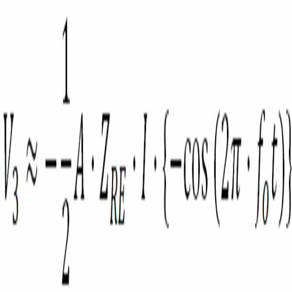
증폭부(340)의 계측 증폭기는 제2 전압(V2)을 증폭하여 제3 전압(V3)을 출력할 수 있다. 제3 전압(V3)은 수학식 7과 같이 표현될 수 있다.The measurement amplifier of the

여기서, V2는 제2 전압이고, V3는 제3 전압이며, A는 계측 증폭기의 전압 이득이고, ZRE는 생체 임피던스의 실수 성분이며, I는 전류원에 의해 공급되는 전류의 크기이고, f1은 제1 주파수이며, f2는 제2 주파수이고, t는 시간이다. 제1 주파수(f1)는 제1 주파수 신호(F1)의 기본 주파수이고, 제2 주파수(f2)는 제2 주파수 신호(F2)의 기본 주파수이다.Here, V 2 is the second voltage, V 3 are first and third voltage, A is the voltage gain of the instrumentation amplifier, Z RE is the real component of the living body impedance, I is the size of the current supplied by the current source, f 1 is a first frequency, f 2 is a second frequency, and t is time. The first frequency f 1 is the fundamental frequency of the first frequency signal F 1 and the second frequency f 2 is the fundamental frequency of the second frequency signal F 2 .
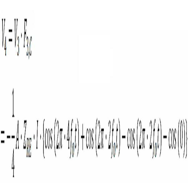
복조부(350)의 초퍼는 제3 주파수 신호(F3)에 의해 구동될 수 있다. 복조부(350)의 초퍼는 제3 전압(V3)을 복조하여, 제4 전압(V4)을 출력할 수 있다. 선택부(360)의 먹스는 복조부(350)의 초퍼에 제공될 제3 주파수 신호(F3)를 선택할 수 있다. 생체 임피던스의 실수 성분을 검출하기 위하여, 선택부(360)의 먹스는 제3 사인 신호(F3,S)와 제3 코사인 신호(F3,C) 중 제3 코사인 신호(F3,C)를 선택할 수 있다. 이 경우, 제4 전압(V4)은 수학식 8과 같이 표현될 수 있다.The chopper of the

여기서, V3은 제3 전압이고, V4는 제4 전압이며, F3,C는 제3 코사인 신호이고, A는 계측 증폭기의 전압 이득이며, ZRE는 생체 임피던스의 실수 성분이고, I는 전류원에 의해 공급되는 전류의 크기이며, f1은 제1 주파수이고, f2는 제2 주파수이며, t는 시간이다. 제3 주파수(f3)는 제3 코사인 신호(F3,C)의 기본 주파수로, 제1 주파수(f1)와 제2 주파수(f2) 사이의 차인 주파수(f1-f2)이다. 제1 주파수(f1)는 제1 주파수 신호(F1)의 기본 주파수이고, 제2 주파수(f2)는 제2 주파수 신호(F2)의 기본 주파수이다.Here, V 3 is the third voltage, V 4 is the fourth voltage, F 3 and C are the third cosine signals, A is the voltage gain of the measurement amplifier, Z RE is the real component of the bioimpedance, F 1 is a first frequency, f 2 is a second frequency, and t is a time. The third frequency f 3 is a fundamental frequency of the third cosine signal F 3 and C and is a frequency f 1 -f 2 that is a difference between the first frequency f 1 and the second frequency f 2 . The first frequency f 1 is the fundamental frequency of the first frequency signal F 1 and the second frequency f 2 is the fundamental frequency of the second frequency signal F 2 .
필터링부(370)의 로우 패스 필터는 차단 주파수 이하 대역의 신호만 통과시킬 수 있다. 차단 주파수가 제3 주파수(f3)인 경우, 필터링부(370)의 출력 전압(Vo)는 수학식 9와 같이 표현될 수 있다.The low-pass filter of the

여기서, Vo는 출력 전압이고, A는 계측 증폭기의 전압이득이며, ZRE는 생체 임피던스의 실수 성분이고, I는 전류원에 의해 공급되는 전류의 크기이다. 수학식 9를 참조하면, 출력 전압(Vo)는 입력 전류(I), 계측 증폭기의 전압 이득(A), 및 생체 임피던스의 실수 성분(ZRE)으로 결정된다.Where V o is the output voltage, A is the voltage gain of the measurement amplifier, Z RE is the real component of the bioimpedance, and I is the magnitude of the current supplied by the current source. Referring to Equation 9, the output voltage Vo is determined by the input current I, the voltage gain A of the measurement amplifier, and the real component Z RE of the bioimpedance .
전술한 바와 같이, 증폭부(340)의 계측 증폭기는 제2 전압(V2)의 모든 주파수 성분을 증폭하는 대신, 계측 증폭기의 대역폭에 포함되는 주파수 성분만을 증폭할 수 있다. 예를 들어, 증폭기의 대역폭은 주파수(f1+f2)에 해당하는 대역을 포함하지 않고, 주파수(f1-f2)에 해당하는 대역을 포함할 수 있다. 이 경우, 수학식 7은 수학식10과 같이 근사화될 수 있다.As described above, the measurement amplifier of the

여기서, V2는 제2 전압이고, V3는 제3 전압이며, A는 계측 증폭기의 전압 이득이고, ZRE는 생체 임피던스의 실수 성분이며, I는 전류원에 의해 공급되는 전류의 크기이고, f1은 제1 주파수이며, f2는 제2 주파수이고, t는 시간이다. 제1 주파수(f1)는 제1 주파수 신호(F1)의 기본 주파수이고, 제2 주파수(f2)는 제2 주파수 신호(F2)의 기본 주파수이다.Here, V 2 is the second voltage, V 3 are first and third voltage, A is the voltage gain of the instrumentation amplifier, Z RE is the real component of the living body impedance, I is the size of the current supplied by the current source, f 1 is a first frequency, f 2 is a second frequency, and t is time. The first frequency f 1 is the fundamental frequency of the first frequency signal F 1 and the second frequency f 2 is the fundamental frequency of the second frequency signal F 2 .
이 경우, 수학식 8은 수학식 11과 같이 근사화될 수 있다.In this case, Equation (8) can be approximated as Equation (11).

여기서, V3은 제3 전압이고, V4는 제4 전압이며, F3,C는 제3 코사인 신호이고, A는 계측 증폭기의 전압 이득이며, ZRE는 생체 임피던스의 실수 성분이고, I는 전류원에 의해 공급되는 전류의 크기이며, f1은 제1 주파수이고, f2는 제2 주파수이며, t는 시간이다. 제3 주파수(f3)는 제3 코사인 신호(F3,C)의 기본 주파수로, 제1 주파수(f1)와 제2 주파수(f2) 사이의 차인 주파수(f1-f2)이다. 제1 주파수(f1)는 제1 주파수 신호(F1)의 기본 주파수이고, 제2 주파수(f2)는 제2 주파수 신호(F2)의 기본 주파수이다.Here, V 3 is the third voltage, V 4 is the fourth voltage, F 3 and C are the third cosine signals, A is the voltage gain of the measurement amplifier, Z RE is the real component of the bioimpedance, F 1 is a first frequency, f 2 is a second frequency, and t is a time. The third frequency f 3 is a fundamental frequency of the third cosine signal F 3 and C and is a frequency f 1 -f 2 that is a difference between the first frequency f 1 and the second frequency f 2 . The first frequency f 1 is the fundamental frequency of the first frequency signal F 1 and the second frequency f 2 is the fundamental frequency of the second frequency signal F 2 .
수학식 7 및 수학식 8이 각각 수학식 10 및 수학식 11로 근사화되는 경우에도, 출력 전압(Vo)는 수학식 9와 동일하게 표현될 수 있다. 이처럼, 증폭부(340)의 계측 증폭기의 대역폭이 감소되더라도, 생체 임피던스가 정확하게 측정될 수 있다.
Even when Equations (7) and (8) are approximated by Equations (10) and (11), the output voltage (V o ) can be expressed in the same manner as Equation (9). As described above, even if the bandwidth of the measurement amplifier of the
다른 예로, 생체 임피던스 측정 회로(300)는 생체 임피던스의 허수 성분(ZIM)을 측정할 수 있다.As another example, the
전류 인가부(310)의 초퍼는 제1 주파수 신호(F1)에 의해 구동될 수 있다. 이 경우, 전류 인가부(310)에 의해 출력된 전류 및 생체 임피던스의 허수 성분(ZIM)으로 인하여 제1 전압(V1)이 발생될 수 있다. 제1 전압(V1)은 수학식 12와 같이 표현될 수 있다.The chopper of the
![]()
![]()
여기서, V1은 제1 전압이고, ZIM는 생체 임피던스의 허수 성분이며, I는 전류원에 의해 공급되는 전류의 크기이고, f1은 제1 주파수이며, t는 시간이다. 제1 주파수(f1)는 제1 주파수 신호(F1)의 기본 주파수이다.Here, V 1 is the first voltage, Z IM is the imaginary component of the bioimpedance, I is the magnitude of the current supplied by the current source, f 1 is the first frequency, and t is the time. The first frequency f 1 is the fundamental frequency of the first frequency signal F 1 .
중간 변조부(330)의 초퍼는 제2 주파수 신호(F2)에 의해 구동될 수 있다. 이 경우, 제1 전압(V1)은 중간 변조부(330)의 초퍼를 통하여 제2 전압(V2)으로 변조될 수 있다. 제2 전압(V2)은 수학식 13과 같이 표현될 수 있다.The chopper of the

여기서, V1은 제1 전압이고, V2는 제2 전압이며, F2는 제2 주파수 신호이고, ZIM는 생체 임피던스의 허수 성분이며, I는 전류원에 의해 공급되는 전류의 크기이고, f1은 제1 주파수이며, t는 시간이고, f2는 제2 주파수이다. 제1 주파수(f1)는 제1 주파수 신호(F1)의 기본 주파수이고, 제2 주파수(f2)는 제2 주파수 신호(F2)의 기본 주파수이다.Here, V 1 is a first voltage, V 2 is the second voltage, F 2 is the second frequency signal, Z IM is the imaginary component of the living body impedance, I is the size of the current supplied by the current source, f 1 is the first frequency, t is time, f 2 is the second frequency. The first frequency f 1 is the fundamental frequency of the first frequency signal F 1 and the second frequency f 2 is the fundamental frequency of the second frequency signal F 2 .
증폭부(340)의 계측 증폭기는 제2 전압(V2)을 증폭하여 제3 전압(V3)을 출력할 수 있다. 제3 전압(V3)은 수학식 14와 같이 표현될 수 있다.The measurement amplifier of the

여기서, V2는 제2 전압이고, V3는 제3 전압이며, A는 계측 증폭기의 전압 이득이고, ZIM는 생체 임피던스의 허수 성분이며, I는 전류원에 의해 공급되는 전류의 크기이고, f1은 제1 주파수이며, f2는 제2 주파수이고, t는 시간이다. 제1 주파수(f1)는 제1 주파수 신호(F1)의 기본 주파수이고, 제2 주파수(f2)는 제2 주파수 신호(F2)의 기본 주파수이다.Here, V 2 is the second voltage, V 3 are first and third voltage, A is the voltage gain of the instrumentation amplifier, Z IM is the imaginary component of the living body impedance, I is the size of the current supplied by the current source, f 1 is a first frequency, f 2 is a second frequency, and t is time. The first frequency f 1 is the fundamental frequency of the first frequency signal F 1 and the second frequency f 2 is the fundamental frequency of the second frequency signal F 2 .
복조부(350)의 초퍼는 제3 주파수 신호(F3)에 의해 구동될 수 있다. 복조부(350)의 초퍼는 제3 전압(V3)을 복조하여, 제4 전압(V4)을 출력할 수 있다. 선택부(360)의 먹스는 복조부(350)의 초퍼에 제공될 제3 주파수 신호(F3)를 선택할 수 있다. 생체 임피던스의 허수 성분을 검출하기 위하여, 선택부(360)의 먹스는 제3 사인 신호(F3,S)와 제3 코사인 신호(F3,C) 중 제3 사인 신호(F3,S)를 선택할 수 있다. 이 경우, 제4 전압(V4)은 수학식 15와 같이 표현될 수 있다.The chopper of the

여기서, V3은 제3 전압이고, V4는 제4 전압이며, F3,S은 제3 사인 신호이고, A는 계측 증폭기의 전압 이득이며, ZIM는 생체 임피던스의 허수 성분이고, I는 전류원에 의해 공급되는 전류의 크기이며, f1은 제1 주파수이고, f2는 제2 주파수이며, t는 시간이다. 제3 주파수(f3)는 제3 사인 신호(F3,S)의 기본 주파수로, 제1 주파수(f1)와 제2 주파수(f2) 사이의 차인 주파수(f1-f2)이다. 제1 주파수(f1)는 제1 주파수 신호(F1)의 기본 주파수이고, 제2 주파수(f2)는 제2 주파수 신호(F2)의 기본 주파수이다.Here, V 3 is the third voltage, V 4 is the is the fourth voltage, F 3, S is the third cause of death signals, and, A is the voltage gain of the instrumentation amplifier, Z IM is the imaginary component of the living body impedance, I is F 1 is a first frequency, f 2 is a second frequency, and t is a time. The third frequency f 3 is a fundamental frequency of the third sine signal F 3 and S and is a frequency f 1 -f 2 that is a difference between the first frequency f 1 and the second frequency f 2 . The first frequency f 1 is the fundamental frequency of the first frequency signal F 1 and the second frequency f 2 is the fundamental frequency of the second frequency signal F 2 .
필터링부(370)의 로우 패스 필터는 차단 주파수 이하 대역의 신호만 통과시킬 수 있다. 차단 주파수가 제3 주파수(f3)인 경우, 필터링부(370)의 출력 전압(Vo)는 수학식 16과 같이 표현될 수 있다.The low-pass filter of the

여기서, Vo는 출력 전압이고, A는 계측 증폭기의 전압이득이며, ZIM는 생체 임피던스의 허수 성분이고, I는 전류원에 의해 공급되는 전류의 크기이다. 수학식 16를 참조하면, 출력 전압(Vo)는 입력 전류(I), 계측 증폭기의 전압 이득(A), 및 생체 임피던스의 허수 성분(ZIM)으로 결정된다.Where V o is the output voltage, A is the voltage gain of the measurement amplifier, Z IM is the imaginary component of the bioimpedance, and I is the magnitude of the current supplied by the current source. Referring to Equation 16, the output voltage Vo is determined by the input current I, the voltage gain A of the measurement amplifier, and the imaginary component Z IM of the bioimpedance.
전술한 바와 같이, 증폭부(340)의 계측 증폭기는 제2 전압(V2)의 모든 주파수 성분을 증폭하는 대신, 계측 증폭기의 대역폭에 포함되는 주파수 성분만을 증폭할 수 있다. 예를 들어, 증폭기의 대역폭은 주파수(f1+f2)에 해당하는 대역을 포함하지 않고, 주파수(f1-f2)에 해당하는 대역을 포함할 수 있다. 이 경우, 수학식 14는 수학식17과 같이 근사화될 수 있다.As described above, the measurement amplifier of the

여기서, V2는 제2 전압이고, V3는 제3 전압이며, A는 계측 증폭기의 전압 이득이고, ZIM는 생체 임피던스의 허수 성분이며, I는 전류원에 의해 공급되는 전류의 크기이고, f1은 제1 주파수이며, f2는 제2 주파수이고, t는 시간이다. 제1 주파수(f1)는 제1 주파수 신호(F1)의 기본 주파수이고, 제2 주파수(f2)는 제2 주파수 신호(F2)의 기본 주파수이다.Here, V 2 is the second voltage, V 3 are first and the third voltage, A is the voltage gain of the instrumentation amplifier, Z IM is the imaginary component of the living body impedance, I is the size of the current supplied by the current source, f 1 is a first frequency, f 2 is a second frequency, and t is time. The first frequency f 1 is the fundamental frequency of the first frequency signal F 1 and the second frequency f 2 is the fundamental frequency of the second frequency signal F 2 .
이 경우, 수학식 15는 수학식 18과 같이 근사화될 수 있다.In this case, Equation (15) can be approximated as Equation (18).

여기서, V3은 제3 전압이고, V4는 제4 전압이며, F3,S는 제3 사인 신호이고, A는 계측 증폭기의 전압 이득이며, ZIM은 생체 임피던스의 허수 성분이고, I는 전류원에 의해 공급되는 전류의 크기이며, f1은 제1 주파수이고, f2는 제2 주파수이며, t는 시간이다. 제3 주파수(f3)는 제3 사인 신호(F3,S)의 기본 주파수로, 제1 주파수(f1)와 제2 주파수(f2) 사이의 차인 주파수(f1-f2)이다. 제1 주파수(f1)는 제1 주파수 신호(F1)의 기본 주파수이고, 제2 주파수(f2)는 제2 주파수 신호(F2)의 기본 주파수이다.Here, V 3 is the third voltage, V 4 is the is the fourth voltage, F 3, S is the third cause of death signals, and, A is the voltage gain of the instrumentation amplifier, Z IM is imaginary component of the living body impedance, I is F 1 is a first frequency, f 2 is a second frequency, and t is a time. The third frequency f 3 is a fundamental frequency of the third sine signal F 3 and S and is a frequency f 1 -f 2 that is a difference between the first frequency f 1 and the second frequency f 2 . The first frequency f 1 is the fundamental frequency of the first frequency signal F 1 and the second frequency f 2 is the fundamental frequency of the second frequency signal F 2 .
수학식 14 및 수학식 15가 각각 수학식 17 및 수학식 18로 근사화되는 경우에도, 출력 전압(Vo)는 수학식 16과 동일하게 표현될 수 있다. 이처럼, 증폭부(340)의 계측 증폭기의 대역폭이 감소되더라도, 생체 임피던스가 정확하게 측정될 수 있다.
Even when Equations (14) and (15) are approximated by Equations (17) and (18), the output voltage (V o ) can be expressed in the same way as in Equation (16). As described above, even if the bandwidth of the measurement amplifier of the
바람직한 실시예에서, 측정하고자 하는 생체 임피던스의 유형에 대응하는 제1 주파수가 2fo인 경우, 제2 주파수는 fo로 결정될 수 있다. 이 경우, 제3 주파수도 fo로 결정될 수 있다. 전술한 바와 같이, 생체 임피던스 측정 장치는 계측 증폭기의 대역폭에 해당하는 fc는 fo보다는 높으나, 2fo보다는 낮은 경우에도, 측정하고자 하는 생체 임피던스를 정확하게 측정할 수 있다. 예를 들어, 제1 주파수가 2fo이고, 제2 주파수 및 제3 주파수가 2fo인 경우, 기존 임피던스 측정 방식에 비해 증폭기의 대역폭 요구사항이 절반으로 감소될 수 있다. If in a preferred embodiment, the first frequency corresponding to the type of living body impedance to be measured is a 2f o, the second frequency may be determined as f o. In this case, the third frequency may also be determined as f o . As described above, the living body impedance measurement apparatus f c corresponding to the bandwidth of the instrumentation amplifier is high but, rather than f o, even if lower than 2f o, it is possible to accurately measure the living body impedance to be measured. For example, if the first frequency is 2f o , and the second and third frequencies are 2f o , the bandwidth requirements of the amplifier may be reduced by half compared to the conventional impedance measurement scheme.
보다 구체적으로, 제1 주파수가 2fo이고, 제2 주파수 및 제3 주파수가 2fo인 경우, 제1 주파수 신호(F1), 제2 주파수 신호(F2), 제3 사인 신호(F3,S), 및 제3 코사인 신호(F3,C)는 각각 수학식 19 내지 수학식 22로 표현될 수 있다.More specifically, when the first frequency is 2f o , and the second frequency and the third frequency are 2f o , the first frequency signal F 1 , the second frequency signal F 2 , the third sine signal F 3 , S ), and the third cosine signal (F3 , C ) can be expressed by Equations (19) to (22), respectively.
![]()
![]()
![]()
![]()
![]()
![]()
![]()
![]()
여기서, F1은 제1 주파수 신호이고, F2는 제2 주파수 신호이며, F3,S는 제3 사인 신호이고, F3,C는 제3 코사인 신호이며, t는 시간이다.Here, F 1 is a first frequency signal, F 2 is a second frequency signal, F 3 and S are third sine signals, F 3 and C are third cosine signals, and t is time.
또한, 생체 임피던스의 실수 성분을 측정하는 경우, 제1 전압(V1), 제2 전압(V2), 제3 전압(V3), 및 제4 전압(V4)은 각각 수학식 23 내지 수학식 26으로 표현될 수 있다.When measuring the real component of the bioimpedance, the first voltage V 1 , the second voltage V 2 , the third voltage V 3 , and the fourth voltage V 4 are expressed by Equations 23, Can be expressed by Equation (26).
![]()
![]()


여기서, V1은 제1 전압이고, V2는 제2 전압이며, V3은 제3 전압이고, V4는 제4 전압이다. ZRE는 생체 임피던스의 실수 성분이고, I는 전류원에 의해 공급되는 전류의 크기이며, t는 시간이다. F2는 제2 주파수 신호이고, F3,C는 제3 코사인 신호이며, A는 계측 증폭기의 전압 이득이다.Here, V 1 is the first voltage, V 2 is the second voltage, V 3 is the third voltage, and V 4 is the fourth voltage. Z RE is the real component of the bioimpedance, I is the magnitude of the current supplied by the current source, and t is the time. F 2 is the second frequency signal, F 3, C is the third cosine signal, and A is the voltage gain of the measurement amplifier.
계측 증폭기의 대역폭에 해당하는 주파수(fc)가 주파수(fo)보다는 크나 주파수(2fo)보다는 작아서, 주파수(2fo) 이상의 주파수 대역에서는 충분한 증폭도를 얻지 못할 수 있다. 이 경우, 수학식 25 및 수학식 26은 각각 수학식 27 및 수학식 28로 근사화될 수 있다.In less than keuna frequency (2f o) than the frequency (f c) corresponding to the bandwidth of the instrumentation amplifier frequency (f o), a frequency (2f o) or more frequency bands can not be obtained a sufficient amplification degree. In this case, equations (25) and (26) can be approximated by equations (27) and (28), respectively.

여기서, V3은 제3 전압이고, V4는 제4 전압이다. A는 계측 증폭기의 전압 이득이고, ZRE는 생체 임피던스의 실수 성분이며, I는 전류원에 의해 공급되는 전류의 크기이고, t는 시간이다.Here, V 3 is the third voltage and V 4 is the fourth voltage. A is the voltage gain of the measurement amplifier, Z RE is the real component of the bioimpedance, I is the magnitude of the current supplied by the current source, and t is the time.
계측 증폭기의 대역폭이 주파수(2fo)보다 낮음으로써 제3 전압(V3) 및 제4 전압(V4)이 수학식 27 및 수학식 28로 근사화되는 경우에도, 출력 전압(Vo)는 계측 증폭기의 대역폭이 주파수(2fo) 이상인 경우와 동일하게 수학식 29로 표현될 수 있다.Even if the instrumentation amplifier bandwidth frequency (2f o) than low by the third voltage (V 3) and a fourth voltage (V 4) is to be approximated by equation 27 and equation 28, the output voltage (V o) is a metrology as in the case more than the bandwidth of the amplifier frequency (2f o) can be expressed by equation 29.

여기서, Vo는 출력 전압이고, A는 계측 증폭기의 전압이득이며, ZRE는 생체 임피던스의 실수 성분이고, I는 전류원에 의해 공급되는 전류의 크기이다.Where V o is the output voltage, A is the voltage gain of the measurement amplifier, Z RE is the real component of the bioimpedance, and I is the magnitude of the current supplied by the current source.
이로 인하여, 실시예들에 따르면 특정 주파수의 임피던스 측정 시 낮은 대역폭의 계측 증폭기를 이용함으로써, 생체 임피던스 측정 회로의 저전력화가 가능하다. 또한, 낮은 대역폭의 계측 증폭기로도 높은 주파수의 생체 임피던스 측정이 가능해진다.Thus, according to the embodiments, the measurement impedance of a specific frequency can be used to reduce the power consumption of the bioimpedance measuring circuit by using a low-bandwidth measurement amplifier. In addition, a measurement impedance of a low frequency can be used to measure a living body impedance.
또한, 생체 임피던스의 허수 성분을 측정하는 경우, 제1 전압(V1), 제2 전압(V2), 제3 전압(V3), 및 제4 전압(V4)은 각각 수학식 30 내지 수학식 33으로 표현될 수 있다.When measuring the imaginary component of the bioimpedance, the first voltage V 1 , the second voltage V 2 , the third voltage V 3 , and the fourth voltage V 4 are expressed by the following equations (30) to Can be expressed by Equation (33).
![]()
![]()


여기서, V1은 제1 전압이고, V2는 제2 전압이며, V3은 제3 전압이고, V4는 제4 전압이다. ZIM는 생체 임피던스의 허수 성분이고, I는 전류원에 의해 공급되는 전류의 크기이며, t는 시간이다. F2는 제2 주파수 신호이고, F3,S는 제3 사인 신호이며, A는 계측 증폭기의 전압 이득이다.Here, V 1 is the first voltage, V 2 is the second voltage, V 3 is the third voltage, and V 4 is the fourth voltage. Z IM is the imaginary component of the bioimpedance, I is the magnitude of the current supplied by the current source, and t is the time. F 2 is the second frequency signal, F 3, S is the third sine signal, and A is the voltage gain of the measurement amplifier.
계측 증폭기의 대역폭에 해당하는 주파수(fc)가 주파수(fo)보다는 크나 주파수(2fo)보다는 작아서, 주파수(2fo) 이상의 주파수 대역에서는 충분한 증폭도를 얻지 못할 수 있다. 이 경우, 수학식 32 및 수학식 33은 각각 수학식 34 및 수학식 35로 근사화될 수 있다.In less than keuna frequency (2f o) than the frequency (f c) corresponding to the bandwidth of the instrumentation amplifier frequency (f o), a frequency (2f o) or more frequency bands can not be obtained a sufficient amplification degree. In this case, equations (32) and (33) can be approximated by equations (34) and (35), respectively.


여기서, V3은 제3 전압이고, V4는 제4 전압이다. A는 계측 증폭기의 전압 이득이고, ZIM는 생체 임피던스의 허수 성분이며, I는 전류원에 의해 공급되는 전류의 크기이고, t는 시간이다.Here, V 3 is the third voltage and V 4 is the fourth voltage. A is the voltage gain of the measurement amplifier, Z IM is the imaginary component of the bioimpedance, I is the magnitude of the current supplied by the current source, and t is the time.
계측 증폭기의 대역폭이 주파수(2fo)보다 낮음으로써 제3 전압(V3) 및 제4 전압(V4)이 수학식 34 및 수학식 35로 근사화되는 경우에도, 출력 전압(Vo)는 계측 증폭기의 대역폭이 주파수(2fo) 이상인 경우와 동일하게 수학식 36로 표현될 수 있다.Even if the instrumentation amplifier bandwidth frequency (2f o) than low by the third voltage (V 3) and that the fourth voltage (V 4) is approximated by equation 34 and equation 35, the output voltage (V o) is a metrology as in the case more than the bandwidth of the amplifier frequency (2f o) can be expressed by equation 36.

여기서, Vo는 출력 전압이고, A는 계측 증폭기의 전압이득이며, ZIM는 생체 임피던스의 허수 성분이고, I는 전류원에 의해 공급되는 전류의 크기이다.Where V o is the output voltage, A is the voltage gain of the measurement amplifier, Z IM is the imaginary component of the bioimpedance, and I is the magnitude of the current supplied by the current source.
이로 인하여, 실시예들에 따르면 특정 주파수의 임피던스 측정 시 낮은 대역폭의 계측 증폭기를 이용함으로써, 생체 임피던스 측정 회로의 저전력화가 가능하다. 또한, 낮은 대역폭의 계측 증폭기로도 높은 주파수의 생체 임피던스 측정이 가능해진다.Thus, according to the embodiments, the measurement impedance of a specific frequency can be used to reduce the power consumption of the bioimpedance measuring circuit by using a low-bandwidth measurement amplifier. In addition, a measurement impedance of a low frequency can be used to measure a living body impedance.
이상에서, 도 3a 및 도 3b에 도시된 초퍼들 각각은 곱셈기(multiplier)로 구현될 수 있다.
In the above, each of the choppers shown in FIGS. 3A and 3B may be implemented as a multiplier.
도 4는 일 실시예에 따른 제어부를 더 포함하는 생체 임피던스 측정 장치를 나타낸 블록도이다. 도 4를 참조하면, 일 실시예에 따른 생체 임피던스 측정 장치(400)는 제어부(160)를 더 포함할 수 있다.4 is a block diagram showing a bioimpedance measuring apparatus further including a controller according to an embodiment. Referring to FIG. 4, the
제어부(160)는 전류 인가부(110)에서 이용되는 제1 주파수, 중간 변조부(120)에서 이용되는 제2 주파수, 및 복조부(140)에서 이용되는 제3 주파수를 결정할 수 있다.The
일 예로, 제어부(160)는 측정하고자 하는 생체 임피던스의 유형에 기초하여 제1 주파수를 결정할 수 있다. 제어부(160)는 매핑 테이블을 이용하여 제1 주파수를 결정할 수 있다. 측정하고자 하는 생체 임피던스의 유형이 결정되면, 제어부(160)는 매핑 테이블을 이용하여 생체 임피던스의 유형에 대응하는 주파수를 결정할 수 있다. 제어부(160)는 생체 임피던스의 유형에 대응하는 주파수를 제1 주파수로 결정할 수 있다.For example, the
제어부(160)는 증폭부(130)의 스펙에 기초하여 제3 주파수를 결정할 수 있다. 예를 들어, 제어부(160)는 복조부(140)에 의해 복조될 제3 주파수의 신호가 증폭부(130)에 의하여 충분히 증폭될 수 있도록, 제3 주파수를 결정할 수 있다. 이 경우, 제어부(160)는 제1 주파수 및 제3 주파수에 기초하여 제2 주파수를 결정할 수 있다. 예를 들어, 제어부(160)는 제1 주파수와 제3 주파수의 차에 해당하는 주파수를 제2 주파수로 결정할 수 있다.The
또는, 제어부(160)는 중간 변조부(120)의 출력 신호가 증폭부(130)의 계측 증폭기의 대역폭 내에 포함될 수 있도록, 제2 주파수를 결정할 수 있다. 보다 구체적으로, 제어부(160)는 제1 주파수에서 제2 주파수를 차감한 값에 해당하는 주파수가 증폭부의 대역폭에 해당하는 주파수(fc) 이하가 되도록, 제2 주파수를 결정할 수 있다. 이 경우, 제어부(160)는 제1 주파수 및 제2 주파수에 기초하여 제3 주파수를 결정할 수 있다. 예를 들어, 제어부(160)는 제1 주파수와 제2 주파수의 차에 해당하는 주파수를 제3 주파수로 결정할 수 있다.Alternatively, the
도면에 도시하지 않았으나, 제어부(160)는 주파수 생성부를 포함할 수 있다. 주파수 생성부는 제1 주파수에 해당하는 제1 주파수 신호, 제2 주파수에 해당하는 제2 주파수 신호, 제3 주파수에 해당하는 제3 사인 신호 및 제3 주파수에 해당하는 제3 코사인 신호를 생성할 수 있다. 제어부(160)는 전류 인가부(110)에 제1 주파수 신호를 제공하고, 중간 변조부(120)에 제2 주파수 신호를 제공하며, 선택부(145)에 제3 사인 신호 및 제3 코사인 신호를 제공할 수 있다. Although not shown in the figure, the
제어부(160)는 선택부(145)의 먹스를 제어하는 선택 신호(SEL)를 제공할 수 있다. 제어부(160)는 생체 임피던스의 실수 성분을 측정하기 위하여, 제1 논리값을 가지는 선택 신호를 선택부(145)에 제공할 수 있다. 또한, 제어부(160)는 생체 임피던스의 허수 성분을 측정하기 위하여 제2 논리값을 가지는 선택 신호를 선택부(145)에 제공할 수 있다.The
제어부(160)는 미리 정해진 주기로 제1 논리값을 가지는 선택 신호와 제2 논리값을 가지는 선택 신호를 선택부(145)에 제공할 수 있다. 이 경우, 선택부(145)는 미리 정해진 주기로 제3 사인 신호 및 제3 코사인 신호를 교대로 선택할 수 있다. 복조부(140)는 생체 임피던스의 실수 성분 및 생체 임피던스의 허수 성분을 미리 정해진 주기마다 교대로 복조할 수 있다.
The
도 5a 및 도 5b는 일 실시예에 따른 제어부를 더 포함하는 생체 임피던스 측정 회로를 설명하는 회로도들이다. 도 5a 및 도 5b를 참조하면, 일 실시예에 따른 생체 임피던스 측정 회로(500)는 제어부(510)를 더 포함할 수 있다.5A and 5B are circuit diagrams illustrating a bioimpedance measuring circuit that further includes a control unit according to an embodiment. 5A and 5B, the
제어부(510)는 전류 인가부(310)에 포함된 초퍼에 제1 주파수 신호(F1)를 제공할 수 있다. 제어부(510)는 중간 변조부(330)에 포함된 초퍼에 제2 주파수 신호(F2)를 제공할 수 있다. 제어부(510)는 선택부(360)에 포함된 먹스에 제3 사인 신호(F3,S) 및 제3 코사인 신호(F3,C)를 제공할 수 있다. 제어부(510)는 선택부(360)에 포함된 먹스에 선택 신호(SEL)를 제공할 수 있다. 제어부(510)에는 도 4를 통하여 기술된 사항들이 그대로 적용될 수 있으므로, 보다 상세한 설명은 생략한다.The
도 5a의 접촉부(320)에 포함된 2개의 단자들은 2 단자 측정법에 따라 생체(325)에 연결될 수 있고, 도 5b의 접촉부(320)에 포함된 4개의 단자들은 4 단자 측정법에 따라 생체(325)에 연결될 수 있다.
The two terminals included in the
도 6은 일 실시예에 따른 복수의 복조부들을 포함하는 생체 임피던스 측정 장치를 나타낸 블록도이다. 도 6을 참조하면, 일 실시예에 따른 생체 임피던스 측정 장치(600)는 실수 성분 복조부(610) 및 허수 성분 복조부(630)를 별도로 포함할 수 있다.6 is a block diagram illustrating a bioimpedance measurement apparatus including a plurality of demodulators according to an embodiment. Referring to FIG. 6, the
실수 성분 복조부(610)는 생체 임피던스의 실수 성분을 측정하기 위하여, 증폭부(130)의 출력 신호를 복조할 수 있다. 허수 성분 복조부(630)는 생체 임피던스의 허수 성분을 측정하기 위하여, 증폭부(130)의 출력 신호를 복조할 수 있다.The
필터링부(620)는 실수 성분 복조부(610)의 출력 신호의 고주파 성분을 제거하고, 필터링부(640)는 허수 성분 복조부(630)의 출력 신호의 고주파 성분을 제거할 수 있다.The
실수 성분 복조부(610) 및 허수 성분 복조부(630)에는 도 1a 내지 도 3b를 통하여 기술된 사항들이 그대로 적용될 수 있으므로, 보다 상세한 설명은 생략한다.
The real
도 7a 및 도 7b는 일 실시예에 따른 복수의 복조부들을 포함하는 생체 임피던스 측정 회로를 설명하는 회로도들이다. 도 7a 및 도 7b를 참조하면, 일 실시예에 따른 생체 임피던스 측정 회로(700)는 전류 인가부(310), 접촉부(320), 중간 변조부(330), 1차 증폭부(750), 제1 복조부(710), 제1 필터링부(720), 제2 복조부(730), 및 제2 필터링부(740)를 포함한다. 제1 복조부(710) 및 제2 복조부(730) 각각은 2차 증폭부 및 초퍼로 구성될 수 있다. 제1 필터링부(720) 및 제2 필터링부(740) 각각은 로우 패스 필터로 구성될 수 있다. 제1 복조부(710)의 초퍼 및 제2 복조부(730)의 초퍼는 제1 증폭부(750)를 구성하는 계측 증폭기의 출력을 입력 받는다. 7A and 7B are circuit diagrams illustrating a bioimpedance measuring circuit including a plurality of demodulators according to an embodiment. 7A and 7B, the
제1 복조부(710)의 2차 증폭부는 제3 전압(V3)을 증폭함으로써 제4 전압(V4)을 출력하고, 제1 복조부(710)의 초퍼는 제3 코사인 신호(F3,C)를 이용하여 제4 전압(V4)을 복조함으로써, 생체 임피던스의 실수 성분을 측정할 수 있다. 제2 복조부(730)의 2차 증폭부는 제3 전압(V3)을 증폭함으로써 제6 전압(V6)을 출력하고, 제2 복조부(730)의 초퍼는 제3 사인 신호(F3,S)를 이용하여 제6 전압(V6)을 복조함으로써, 생체 임피던스의 허수 성분을 측정할 수 있다.The second amplifying unit of the
제1 복조부(710)의 초퍼 및 제2 복조부(730)의 초퍼에는 도 1a 내지 도 3b, 및 도 6을 통하여 기술된 사항들이 그대로 적용될 수 있으므로, 보다 상세한 설명은 생략한다. 또한, 도 7a의 접촉부(320)에 포함된 2개의 단자들은 2 단자 측정법에 따라 생체(325)에 연결될 수 있고, 도 7b의 접촉부(320)에 포함된 4개의 단자들은 4 단자 측정법에 따라 생체(325)에 연결될 수 있다.
The chopper of the
도 8은 일 실시예에 따른 생체 임피던스 측정 방법을 나타낸 동작 흐름도이다. 도 8을 참조하면, 일 실시예에 따른 생체 임피던스 측정 방법은 제1 주파수의 전류를 생체와 접촉된 전극들에 제공하는 단계(810), 제2 주파수를 이용하여, 전류가 생체를 통해 흐름으로써 발생된 전압을 변조하는 단계(820), 증폭기를 이용하여 변조된 전압을 증폭하는 단계(830), 및 제3 주파수를 이용하여 증폭된 전압을 복조하는 단계(840)를 포함한다. 생체 임피던스 측정 방법은 복조된 전압의 주파수 대역 중 제3 주파수보다 높은 대역의 신호를 필터링하여 제거하는 단계(850)를 더 포함할 수 있다.8 is a flowchart illustrating a method of measuring a bioimpedance according to an embodiment of the present invention. Referring to FIG. 8, a bio-impedance measuring method according to an exemplary embodiment includes providing (810) a current of a first frequency to electrodes contacted with a living body, using a second frequency, A
도 8에 도시된 각 단계들에는 도 1a 내지 도 7b를 통하여 기술된 사항들이 그대로 적용될 수 있으므로, 보다 상세한 설명은 생략한다.
The steps described in FIG. 1A through FIG. 7B may be applied to each step shown in FIG. 8, so that a detailed description will be omitted.
도 9는 일 실시예에 따른 주파수들을 결정하는 방법을 나타낸 동작 흐름도이다. 도 9를 참조하면, 일 실시예에 따른 주파수들을 결정하는 방법은 측정하려는 생체 임피던스의 유형에 기초하여 제1 주파수를 결정하는 단계(910), 증폭기의 대역폭에 기초하여 제3 주파수를 결정하는 단계(920), 및 제1 주파수 및 제3 주파수에 기초하여 제2 주파수를 결정하는 단계(930)를 포함한다.9 is an operational flow diagram illustrating a method for determining frequencies in accordance with one embodiment. Referring to FIG. 9, a method for determining frequencies according to an embodiment includes determining 910 a first frequency based on the type of bio-impedance to be measured, determining a third frequency based on the bandwidth of the amplifier (920), and determining (930) a second frequency based on the first frequency and the third frequency.
일 예로, 주파수들을 결정하는 방법은 도 4의 제어부(160), 도 5a의 제어부(510), 또는 도 5b의 제어부(510)에 의해 수행될 수 있다. 예를 들어, 증폭부의 대역폭은 10 kHz이고, 전류 인가부로부터 출력되는 교류 전류의 주파수가 100 kHz일 수 있다. 제어부는 제3 주파수가 증폭부의 대역폭 내에 충분히 들어 오도록 제3 주파수를 2 kHz로 결정할 수 있다. 나아가, 제어부는 제1 주파수로부터 제3 주파수를 차감함으로써, 제 2 주파수를 결정할 수 있다. 제2 주파수는 100 kHz - 2 kHz = 98 kHz로 결정될 수 있다.
For example, the method of determining frequencies may be performed by the
이상에서 설명된 실시예들은 하드웨어 구성요소, 소프트웨어 구성요소, 및/또는 하드웨어 구성요소 및 소프트웨어 구성요소의 조합으로 구현될 수 있다. 예를 들어, 실시예들에서 설명된 장치, 방법 및 구성요소는, 예를 들어, 프로세서, 콘트롤러, ALU(arithmetic logic unit), 디지털 신호 프로세서(digital signal processor), 마이크로컴퓨터, FPGA(field programmable gate array), PLU(programmable logic unit), 마이크로프로세서, 또는 명령(instruction)을 실행하고 응답할 수 있는 다른 어떠한 장치와 같이, 하나 이상의 범용 컴퓨터 또는 특수 목적 컴퓨터를 이용하여 구현될 수 있다. 처리 장치는 운영 체제(OS) 및 상기 운영 체제 상에서 수행되는 하나 이상의 소프트웨어 애플리케이션을 수행할 수 있다. 또한, 처리 장치는 소프트웨어의 실행에 응답하여, 데이터를 접근, 저장, 조작, 처리 및 생성할 수도 있다. 이해의 편의를 위하여, 처리 장치는 하나가 사용되는 것으로 설명된 경우도 있지만, 해당 기술분야에서 통상의 지식을 가진 자는, 처리 장치가 복수 개의 처리 요소(processing element) 및/또는 복수 유형의 처리 요소를 포함할 수 있음을 알 수 있다. 예를 들어, 처리 장치는 복수 개의 프로세서 또는 하나의 프로세서 및 하나의 콘트롤러를 포함할 수 있다. 또한, 병렬 프로세서(parallel processor)와 같은, 다른 처리 구성(processing configuration)도 가능하다.The embodiments described above may be implemented in hardware components, software components, and / or a combination of hardware components and software components. For example, the devices, methods, and components described in the embodiments may be implemented within a computer system, such as, for example, a processor, a controller, an arithmetic logic unit (ALU), a digital signal processor, such as an array, a programmable logic unit (PLU), a microprocessor, or any other device capable of executing and responding to instructions. The processing device may execute an operating system (OS) and one or more software applications running on the operating system. The processing device may also access, store, manipulate, process, and generate data in response to execution of the software. For ease of understanding, the processing apparatus may be described as being used singly, but those skilled in the art will recognize that the processing apparatus may have a plurality of processing elements and / As shown in FIG. For example, the processing unit may comprise a plurality of processors or one processor and one controller. Other processing configurations are also possible, such as a parallel processor.
소프트웨어는 컴퓨터 프로그램(computer program), 코드(code), 명령(instruction), 또는 이들 중 하나 이상의 조합을 포함할 수 있으며, 원하는 대로 동작하도록 처리 장치를 구성하거나 독립적으로 또는 결합적으로(collectively) 처리 장치를 명령할 수 있다. 소프트웨어 및/또는 데이터는, 처리 장치에 의하여 해석되거나 처리 장치에 명령 또는 데이터를 제공하기 위하여, 어떤 유형의 기계, 구성요소(component), 물리적 장치, 가상 장치(virtual equipment), 컴퓨터 저장 매체 또는 장치, 또는 전송되는 신호 파(signal wave)에 영구적으로, 또는 일시적으로 구체화(embody)될 수 있다. 소프트웨어는 네트워크로 연결된 컴퓨터 시스템 상에 분산되어서, 분산된 방법으로 저장되거나 실행될 수도 있다. 소프트웨어 및 데이터는 하나 이상의 컴퓨터 판독 가능 기록 매체에 저장될 수 있다.The software may include a computer program, code, instructions, or a combination of one or more of the foregoing, and may be configured to configure the processing device to operate as desired or to process it collectively or collectively Device can be commanded. The software and / or data may be in the form of any type of machine, component, physical device, virtual equipment, computer storage media, or device , Or may be permanently or temporarily embodied in a transmitted signal wave. The software may be distributed over a networked computer system and stored or executed in a distributed manner. The software and data may be stored on one or more computer readable recording media.
실시예에 따른 방법은 다양한 컴퓨터 수단을 통하여 수행될 수 있는 프로그램 명령 형태로 구현되어 컴퓨터 판독 가능 매체에 기록될 수 있다. 상기 컴퓨터 판독 가능 매체는 프로그램 명령, 데이터 파일, 데이터 구조 등을 단독으로 또는 조합하여 포함할 수 있다. 상기 매체에 기록되는 프로그램 명령은 실시예를 위하여 특별히 설계되고 구성된 것들이거나 컴퓨터 소프트웨어 당업자에게 공지되어 사용 가능한 것일 수도 있다. 컴퓨터 판독 가능 기록 매체의 예에는 하드 디스크, 플로피 디스크 및 자기 테이프와 같은 자기 매체(magnetic media), CD-ROM, DVD와 같은 광기록 매체(optical media), 플롭티컬 디스크(floptical disk)와 같은 자기-광 매체(magneto-optical media), 및 롬(ROM), 램(RAM), 플래시 메모리 등과 같은 프로그램 명령을 저장하고 수행하도록 특별히 구성된 하드웨어 장치가 포함된다. 프로그램 명령의 예에는 컴파일러에 의해 만들어지는 것과 같은 기계어 코드뿐만 아니라 인터프리터 등을 사용해서 컴퓨터에 의해서 실행될 수 있는 고급 언어 코드를 포함한다. 상기된 하드웨어 장치는 실시예의 동작을 수행하기 위해 하나 이상의 소프트웨어 모듈로서 작동하도록 구성될 수 있으며, 그 역도 마찬가지이다.The method according to an embodiment may be implemented in the form of a program command that can be executed through various computer means and recorded in a computer-readable medium. The computer-readable medium may include program instructions, data files, data structures, and the like, alone or in combination. The program instructions to be recorded on the medium may be those specially designed and configured for the embodiments or may be available to those skilled in the art of computer software. Examples of computer-readable media include magnetic media such as hard disks, floppy disks and magnetic tape; optical media such as CD-ROMs and DVDs; magnetic media such as floppy disks; Magneto-optical media, and hardware devices specifically configured to store and execute program instructions such as ROM, RAM, flash memory, and the like. Examples of program instructions include machine language code such as those produced by a compiler, as well as high-level language code that can be executed by a computer using an interpreter or the like. The hardware devices described above may be configured to operate as one or more software modules to perform the operations of the embodiments, and vice versa.
이상과 같이 실시예들이 비록 한정된 실시예와 도면에 의해 설명되었으나, 해당 기술분야에서 통상의 지식을 가진 자라면 상기의 기재로부터 다양한 수정 및 변형이 가능하다. 예를 들어, 설명된 기술들이 설명된 방법과 다른 순서로 수행되거나, 및/또는 설명된 시스템, 구조, 장치, 회로 등의 구성요소들이 설명된 방법과 다른 형태로 결합 또는 조합되거나, 다른 구성요소 또는 균등물에 의하여 대치되거나 치환되더라도 적절한 결과가 달성될 수 있다. 그러므로, 다른 구현들, 다른 실시예들 및 특허청구범위와 균등한 것들도 후술하는 특허청구범위의 범위에 속한다.
While the present invention has been particularly shown and described with reference to exemplary embodiments thereof, it is to be understood that the invention is not limited to the disclosed exemplary embodiments. For example, it is to be understood that the techniques described may be performed in a different order than the described methods, and / or that components of the described systems, structures, devices, circuits, Lt; / RTI > or equivalents, even if it is replaced or replaced. Therefore, other implementations, other embodiments, and equivalents to the claims are also within the scope of the following claims.
Claims (23)
제2 주파수를 이용하여, 상기 전류가 생체를 통해 흐름으로써 발생되는 전압을 변조하는 중간 변조부;
변조된 전압을 증폭하는 증폭부; 및
제3 주파수를 이용하여, 증폭된 전압을 복조하는 복조부
를 포함하는 생체 임피던스 측정 장치.
A current applying unit for outputting a current of a first frequency;
An intermediate modulator for modulating a voltage generated by flowing the current through the living body using a second frequency;
An amplifier for amplifying the modulated voltage; And
A demodulator for demodulating the amplified voltage using the third frequency,
And measuring the impedance of the living body.
상기 제3 주파수는 상기 제1 주파수와 상기 제2 주파수 사이의 차이에 해당하는, 생체 임피던스 측정 장치.
The method according to claim 1,
And the third frequency corresponds to a difference between the first frequency and the second frequency.
상기 제3 주파수는 상기 증폭부의 대역폭에 의해 결정되는, 생체 임피던스 측정 장치.
The method according to claim 1,
And the third frequency is determined by the bandwidth of the amplification unit.
상기 제2 주파수는 상기 제1 주파수에서 상기 제2 주파수를 차감한 값에 해당하는 주파수가 상기 증폭부의 대역폭에 포함되도록 결정되는, 생체 임피던스 측정 장치.
The method of claim 3,
Wherein the second frequency is determined such that a frequency corresponding to a value obtained by subtracting the second frequency from the first frequency is included in the bandwidth of the amplification unit.
상기 제1 주파수는 측정하려는 생체 임피던스의 유형에 대응되는, 생체 임피던스 측정 장치.
The method according to claim 1,
Wherein the first frequency corresponds to a type of a living body impedance to be measured.
상기 증폭부는 상기 변조된 전압의 주파수 대역 중 상기 제1 주파수에서 상기 제2 주파수를 차감한 값에 해당하는 주파수 이하 대역의 신호를 증폭하는, 생체 임피던스 측정 장치.
The method according to claim 1,
Wherein the amplifying unit amplifies a signal of a sub-frequency band corresponding to a value obtained by subtracting the second frequency from the first frequency among the frequency bands of the modulated voltage.
상기 중간 변조부는 상기 제1 주파수에 상기 제2 주파수를 합산한 주파수의 제1 중간 신호와 상기 제1 주파수에서 상기 제2 주파수를 차감한 주파수의 제2 중간 신호를 생성하고,
상기 증폭부는 상기 제1 중간 신호 및 상기 제2 중간 신호 중 상기 제2 중간 신호를 선택적으로 증폭하는, 생체 임피던스 측정 장치.
The method according to claim 1,
The intermediate modulator generates a first intermediate signal of a frequency obtained by adding the second frequency to the first frequency and a second intermediate signal of a frequency obtained by subtracting the second frequency from the first frequency,
Wherein the amplifying unit selectively amplifies the second intermediate signal among the first intermediate signal and the second intermediate signal.
제1 신호와 제2 신호 중 어느 하나를 선택하는 선택부
를 더 포함하고,
상기 복조부는 선택된 신호를 이용하여 상기 증폭된 전압을 복조하며, 상기 제1 신호 및 상기 제2 신호는 상기 제1 주파수와 상기 제2 주파수 사이의 차이에 해당하는 주파수를 가지고, 상기 제1 신호와 상기 제2 신호는 서로 다른 위상을 가지는, 생체 임피던스 측정 장치.
The method according to claim 1,
A selection unit for selecting either the first signal or the second signal,
Further comprising:
Wherein the demodulator demodulates the amplified voltage using a selected signal and the first signal and the second signal have a frequency corresponding to the difference between the first frequency and the second frequency, And the second signal has a different phase.
상기 선택부는 생체 임피던스의 실수 성분을 측정하기 위하여 상기 제1 신호를 선택하고, 상기 생체 임피던스의 허수 성분을 측정하기 위하여 상기 제2 신호를 선택하는, 생체 임피던스 측정 장치.
9. The method of claim 8,
Wherein the selection unit selects the first signal to measure the real component of the bioimpedance and selects the second signal to measure the imaginary component of the bioimpedance.
상기 선택부는 미리 정해진 주기로 상기 제1 신호와 상기 제2 신호를 교대로 선택하는, 생체 임피던스 측정 장치.
9. The method of claim 8,
Wherein the selecting unit alternately selects the first signal and the second signal at a predetermined period.
복조된 전압의 주파수 대역 중 상기 제3 주파수보다 높은 대역의 신호를 필터링하는 필터링부
를 더 포함하는 생체 임피던스 측정 장치.
The method according to claim 1,
And a filtering unit for filtering a signal of a band higher than the third frequency among the frequency bands of the demodulated voltage,
Further comprising: a bioimpedance measuring device for measuring bioimpedance.
상기 변조된 전류가 상기 생체에 흐르도록 상기 생체와 접촉하는 접촉부;
를 더 포함하는 생체 임피던스 측정 장치.
The method according to claim 1,
A contact portion contacting the living body such that the modulated current flows in the living body;
Further comprising: a bioimpedance measuring device for measuring bioimpedance.
제2 주파수를 이용하여, 상기 전류가 상기 생체를 통해 흐름으로써 발생되는 전압을 변조하는 단계;
증폭기를 이용하여, 변조된 전압을 증폭하는 단계; 및
제3 주파수를 이용하여, 증폭된 전압을 복조하는 단계
를 포함하는 생체 임피던스 측정 방법.
Providing a current of a first frequency to the electrodes in contact with the living body;
Using a second frequency, modulating a voltage generated by flowing the current through the living body;
Amplifying the modulated voltage using an amplifier; And
Using the third frequency, demodulating the amplified voltage
And measuring the impedance of the living body.
측정하려는 생체 임피던스의 유형에 기초하여 상기 제1 주파수를 결정하는 단계;
상기 증폭기의 대역폭에 기초하여 상기 제3 주파수를 결정하는 단계; 및
상기 제1 주파수 및 상기 제3 주파수에 기초하여 상기 제2 주파수를 결정하는 단계
를 더 포함하는 생체 임피던스 측정 방법.
14. The method of claim 13,
Determining the first frequency based on the type of bioimpedance to be measured;
Determining the third frequency based on a bandwidth of the amplifier; And
Determining the second frequency based on the first frequency and the third frequency
And measuring the impedance of the living body.
상기 제2 주파수를 결정하는 단계에서,
상기 제2 주파수는 상기 제1 주파수와 상기 제3 주파수 사이의 차이에 해당하는 주파수로 결정되는, 생체 임피던스 측정 방법.
15. The method of claim 14,
In determining the second frequency,
Wherein the second frequency is determined as a frequency corresponding to a difference between the first frequency and the third frequency.
상기 제3 주파수를 결정하는 단계에서,
상기 제3 주파수는 상기 제3 주파수가 상기 증폭기의 대역폭에 포함되도록 결정되는, 생체 임피던스 측정 방법.
15. The method of claim 14,
In determining the third frequency,
Wherein the third frequency is determined such that the third frequency is included in the bandwidth of the amplifier.
상기 변조된 전압을 증폭하는 단계에서,
상기 변조된 전압의 주파수 대역 중 상기 제1 주파수에서 상기 제2 주파수를 차감한 값에 해당하는 주파수 이하 대역의 신호가 증폭되는, 생체 임피던스 측정 방법.
14. The method of claim 13,
In the step of amplifying the modulated voltage,
Wherein a signal of a sub-frequency band corresponding to a value obtained by subtracting the second frequency from the first frequency among the frequency bands of the modulated voltage is amplified.
상기 발생된 전압을 변조하는 단계에서,
상기 제1 주파수에 상기 제2 주파수를 합산한 주파수의 제1 중간 신호와 상기 제1 주파수에서 상기 제2 주파수를 차감한 주파수의 제2 중간 신호가 생성되고,
상기 변조된 전압을 증폭하는 단계에서,
상기 제1 중간 신호 및 상기 제2 중간 신호 중 상기 제2 중간 신호가 선택적으로 증폭되는, 생체 임피던스 측정 방법.
14. The method of claim 13,
In modulating the generated voltage,
A first intermediate signal of a frequency obtained by adding the second frequency to the first frequency and a second intermediate signal of a frequency obtained by subtracting the second frequency from the first frequency are generated,
In the step of amplifying the modulated voltage,
Wherein the second intermediate signal of the first intermediate signal and the second intermediate signal is selectively amplified.
상기 복조하는 단계는
제1 신호와 제2 신호 중 어느 하나를 상기 제3 주파수로 선택하는 단계
를 포함하고,
상기 제1 신호 및 상기 제2 신호는 상기 제1 주파수와 상기 제2 주파수 사이의 차이에 해당하는 주파수를 가지며, 상기 제1 신호와 상기 제2 신호는 서로 다른 위상을 가지는, 생체 임피던스 측정 방법.
14. The method of claim 13,
The demodulating step
Selecting either the first signal or the second signal as the third frequency
Lt; / RTI >
Wherein the first signal and the second signal have a frequency corresponding to a difference between the first frequency and the second frequency, and the first signal and the second signal have different phases.
상기 선택하는 단계에서,
생체 임피던스의 실수 성분을 측정하기 위하여 상기 제1 신호가 선택되고, 상기 생체 임피던스의 허수 성분을 측정하기 위하여 상기 제2 신호가 선택되는, 생체 임피던스 측정 방법.
20. The method of claim 19,
In the selecting step,
The first signal is selected to measure the real component of the bioimpedance and the second signal is selected to measure the imaginary component of the bioimpedance.
상기 선택하는 단계에서,
미리 정해진 주기로 상기 제1 신호와 상기 제2 신호가 교대로 선택되는, 생체 임피던스 측정 방법.
20. The method of claim 19,
In the selecting step,
Wherein the first signal and the second signal are alternately selected at predetermined intervals.
복조된 전압의 주파수 대역 중 상기 제3 주파수보다 높은 대역의 신호를 필터링하는 단계
를 더 포함하는 생체 임피던스 측정 방법.
14. The method of claim 13,
Filtering the signal of the band higher than the third frequency among the frequency bands of the demodulated voltage
And measuring the impedance of the living body.
A computer-readable recording medium having recorded thereon a program for executing the method according to any one of claims 13 to 22.
Priority Applications (4)
| Application Number | Priority Date | Filing Date | Title |
|---|---|---|---|
| KR1020140007377A KR101987408B1 (en) | 2014-01-21 | 2014-01-21 | Apparatus and method of measuring bio impedence |
| EP15151780.2A EP2896360B1 (en) | 2014-01-21 | 2015-01-20 | Apparatus and method of measuring bio impedance |
| US14/600,670 US9763595B2 (en) | 2014-01-21 | 2015-01-20 | Apparatus and method of measuring bio impedance |
| CN201510031205.0A CN104783792B (en) | 2014-01-21 | 2015-01-21 | Measure the device and method of bio-impedance |
Applications Claiming Priority (1)
| Application Number | Priority Date | Filing Date | Title |
|---|---|---|---|
| KR1020140007377A KR101987408B1 (en) | 2014-01-21 | 2014-01-21 | Apparatus and method of measuring bio impedence |
Publications (2)
| Publication Number | Publication Date |
|---|---|
| KR20150087020A true KR20150087020A (en) | 2015-07-29 |
| KR101987408B1 KR101987408B1 (en) | 2019-06-11 |
Family
ID=52354842
Family Applications (1)
| Application Number | Title | Priority Date | Filing Date |
|---|---|---|---|
| KR1020140007377A KR101987408B1 (en) | 2014-01-21 | 2014-01-21 | Apparatus and method of measuring bio impedence |
Country Status (4)
| Country | Link |
|---|---|
| US (1) | US9763595B2 (en) |
| EP (1) | EP2896360B1 (en) |
| KR (1) | KR101987408B1 (en) |
| CN (1) | CN104783792B (en) |
Cited By (6)
| Publication number | Priority date | Publication date | Assignee | Title |
|---|---|---|---|---|
| KR20180023580A (en) * | 2016-08-26 | 2018-03-07 | 황인오 | Apparatus and method for measuring skin moisture |
| KR20180047088A (en) * | 2016-10-31 | 2018-05-10 | 인천대학교 산학협력단 | Apparatus for measuring skin condition, method and computer program for providing skin condition information using thereof |
| KR20190048298A (en) * | 2017-10-31 | 2019-05-09 | 한국 한의학 연구원 | Apparatus and method of obtaining the health information using multi-frequency bio-impedance measurement |
| KR20200049429A (en) * | 2018-10-31 | 2020-05-08 | 한국 한의학 연구원 | Method and device for diagnosing weakness using biological signals |
| KR20210131104A (en) * | 2020-04-23 | 2021-11-02 | 울산과학기술원 | Bio-impedance instrumentation system |
| KR20220094178A (en) * | 2020-12-28 | 2022-07-05 | 한국과학기술원 | Impedance measuring apparatus and impedance measuring method |
Families Citing this family (10)
| Publication number | Priority date | Publication date | Assignee | Title |
|---|---|---|---|---|
| US20190192064A1 (en) * | 2012-09-12 | 2019-06-27 | Mb Device Llc | Micro-device and system for determining physiological condition of cervical tissue |
| US10653333B2 (en) | 2014-11-13 | 2020-05-19 | Ori Diagnostic Instruments, LLC | Systems and methods for high frequency impedance spectroscopy detection of daily changes of dielectric properties of the human body to measure body composition and hydration status |
| US10401465B2 (en) * | 2016-12-15 | 2019-09-03 | Stmicroelectronics S.R.L. | Compensation and calibration for a low power bio-impedance measurement device |
| TWI598073B (en) * | 2016-12-15 | 2017-09-11 | 財團法人工業技術研究院 | Physiological signal measuring method and physiological signal measuring device |
| KR20180087043A (en) * | 2017-01-24 | 2018-08-01 | 삼성전자주식회사 | Apparatus and method for measuring bioelectric impedance, Apparatus and method for measuring biometric information |
| CN111134674B (en) * | 2018-11-09 | 2021-10-08 | 上海交通大学 | Bioelectrical impedance tomography system based on frequency division multiplexing data compression technology |
| DE102019203052B4 (en) * | 2019-03-06 | 2022-01-13 | Technische Hochschule Lübeck | Method and device for detecting diaphragmatic contractions |
| EP3957240A4 (en) * | 2019-04-15 | 2022-04-20 | Msheaf Health Management Technologies Limited | Non-invasive method and system for detecting feature information of in vivo tissue |
| WO2020232706A1 (en) * | 2019-05-23 | 2020-11-26 | 麦层移动健康管理有限公司 | Method and device for measuring body fluid and its changes and for measuring blood flow changes |
| CN111141786A (en) * | 2020-03-02 | 2020-05-12 | 北京他山科技有限公司 | Method for detecting maturity of roasted meat in real time |
Citations (6)
| Publication number | Priority date | Publication date | Assignee | Title |
|---|---|---|---|---|
| US5631555A (en) * | 1994-09-29 | 1997-05-20 | Hamamatsu Photonics K.K. | Voltage measurement system |
| US20010051774A1 (en) * | 2000-02-28 | 2001-12-13 | Peter Littrup | Multidimensional bioelectrical tissue analyzer |
| US20070043303A1 (en) * | 2005-08-17 | 2007-02-22 | Osypka Markus J | Method and apparatus for digital demodulation and further processing of signals obtained in the measurement of electrical bioimpedance or bioadmittance in an object |
| US20080183098A1 (en) * | 2007-01-31 | 2008-07-31 | Medtronic, Inc. | Chopper-stabilized instrumentation amplifier for impedance measurement |
| US20100327887A1 (en) * | 2007-01-31 | 2010-12-30 | Medtronic, Inc. | Chopper-stabilized instrumentation amplifier for impedance measurement |
| DE102011002413A1 (en) * | 2011-01-04 | 2012-07-05 | Robert Bosch Gmbh | Backscatter imaging device for imaging has lock-in amplifier that generates output signal by correlating intermediate frequency signal with correlation signal |
Family Cites Families (23)
| Publication number | Priority date | Publication date | Assignee | Title |
|---|---|---|---|---|
| DE2651031C2 (en) | 1976-11-09 | 1982-04-01 | Bruker Medizintechnik Gmbh, 7512 Rheinstetten | Defibrillator |
| JP2672327B2 (en) | 1988-05-10 | 1997-11-05 | シチズン時計株式会社 | Biological information measurement device |
| US5382956A (en) | 1992-04-30 | 1995-01-17 | Hewlett Packard Co | Integrated circuit for physiological signal measurement |
| US5206602A (en) | 1992-04-30 | 1993-04-27 | Hewlett-Packard Company | Biomedical amplifier circuit |
| US6525862B2 (en) * | 1996-10-30 | 2003-02-25 | Photogen, Inc. | Methods and apparatus for optical imaging |
| CA2452367C (en) | 2001-07-06 | 2008-10-28 | Aspect Medical Systems, Inc. | System and method for measuring bioelectric impedance in the presence of interference |
| KR100707984B1 (en) | 2003-02-22 | 2007-04-16 | 송철규 | Device and Method for motion analysis with bio-impedance |
| WO2005122889A1 (en) * | 2004-06-18 | 2005-12-29 | Tallinn University Of Technology | Simultaneous discrete-time analysis of features of substances |
| EP2002213B1 (en) * | 2006-03-29 | 2012-07-11 | Rosemount, Inc. | Capacitance sensing circuit |
| US7385443B1 (en) | 2007-01-31 | 2008-06-10 | Medtronic, Inc. | Chopper-stabilized instrumentation amplifier |
| KR20070044825A (en) | 2007-04-10 | 2007-04-30 | 이영국 | 2-point body fat analysing method not using steady-alternate current source |
| US7714757B2 (en) | 2007-09-26 | 2010-05-11 | Medtronic, Inc. | Chopper-stabilized analog-to-digital converter |
| US8938292B2 (en) | 2008-07-31 | 2015-01-20 | Medtronic, Inc. | Estimating cardiovascular pressure and volume using impedance measurements |
| US8922274B2 (en) | 2008-10-20 | 2014-12-30 | The Regents Of The University Of Michigan | Bioamplifier for neural interfaces |
| EP2294979B1 (en) | 2009-09-14 | 2013-12-18 | Imec | Method and electronic medical device for simultaneously measuring an impedance and a biopotential signal |
| KR101056016B1 (en) | 2009-10-06 | 2011-08-10 | 한국과학기술원 | Apparatus, method and diagnostic system comprising the same |
| KR101101118B1 (en) | 2010-04-28 | 2012-01-05 | 주식회사 엠아이텍 | Impedance measuring apparatus of stimulation electrodes for the neural stimulators |
| KR20120068430A (en) | 2010-12-17 | 2012-06-27 | 주식회사 샤인 | Device for measuring blood ion and viscosity state |
| KR101114720B1 (en) | 2011-02-15 | 2012-03-02 | 주식회사 바이오스페이스 | Apparatus and method for measuring bio-Impedance |
| ITMI20111177A1 (en) | 2011-06-28 | 2012-12-29 | St Microelectronics Srl | METHOD AND DEVICE FOR MEASURING THE ELECTRICAL IMPEDANCE OF BIOLOGICAL FABRICS |
| JP2013128716A (en) | 2011-12-22 | 2013-07-04 | Renesas Electronics Corp | Bioelectric impedance measuring apparatus |
| JP2013132326A (en) | 2011-12-26 | 2013-07-08 | Tanita Corp | Bioimpedance measuring device and bioimpedance measurement method |
| KR102026740B1 (en) | 2012-02-07 | 2019-09-30 | 삼성전자주식회사 | Electrode for measuring bio-signal and a method thereof, and system for measuring bio-signal |
-
2014
- 2014-01-21 KR KR1020140007377A patent/KR101987408B1/en active IP Right Grant
-
2015
- 2015-01-20 EP EP15151780.2A patent/EP2896360B1/en active Active
- 2015-01-20 US US14/600,670 patent/US9763595B2/en active Active
- 2015-01-21 CN CN201510031205.0A patent/CN104783792B/en active Active
Patent Citations (6)
| Publication number | Priority date | Publication date | Assignee | Title |
|---|---|---|---|---|
| US5631555A (en) * | 1994-09-29 | 1997-05-20 | Hamamatsu Photonics K.K. | Voltage measurement system |
| US20010051774A1 (en) * | 2000-02-28 | 2001-12-13 | Peter Littrup | Multidimensional bioelectrical tissue analyzer |
| US20070043303A1 (en) * | 2005-08-17 | 2007-02-22 | Osypka Markus J | Method and apparatus for digital demodulation and further processing of signals obtained in the measurement of electrical bioimpedance or bioadmittance in an object |
| US20080183098A1 (en) * | 2007-01-31 | 2008-07-31 | Medtronic, Inc. | Chopper-stabilized instrumentation amplifier for impedance measurement |
| US20100327887A1 (en) * | 2007-01-31 | 2010-12-30 | Medtronic, Inc. | Chopper-stabilized instrumentation amplifier for impedance measurement |
| DE102011002413A1 (en) * | 2011-01-04 | 2012-07-05 | Robert Bosch Gmbh | Backscatter imaging device for imaging has lock-in amplifier that generates output signal by correlating intermediate frequency signal with correlation signal |
Cited By (6)
| Publication number | Priority date | Publication date | Assignee | Title |
|---|---|---|---|---|
| KR20180023580A (en) * | 2016-08-26 | 2018-03-07 | 황인오 | Apparatus and method for measuring skin moisture |
| KR20180047088A (en) * | 2016-10-31 | 2018-05-10 | 인천대학교 산학협력단 | Apparatus for measuring skin condition, method and computer program for providing skin condition information using thereof |
| KR20190048298A (en) * | 2017-10-31 | 2019-05-09 | 한국 한의학 연구원 | Apparatus and method of obtaining the health information using multi-frequency bio-impedance measurement |
| KR20200049429A (en) * | 2018-10-31 | 2020-05-08 | 한국 한의학 연구원 | Method and device for diagnosing weakness using biological signals |
| KR20210131104A (en) * | 2020-04-23 | 2021-11-02 | 울산과학기술원 | Bio-impedance instrumentation system |
| KR20220094178A (en) * | 2020-12-28 | 2022-07-05 | 한국과학기술원 | Impedance measuring apparatus and impedance measuring method |
Also Published As
| Publication number | Publication date |
|---|---|
| EP2896360B1 (en) | 2022-09-07 |
| CN104783792B (en) | 2019-09-13 |
| KR101987408B1 (en) | 2019-06-11 |
| US9763595B2 (en) | 2017-09-19 |
| US20150201861A1 (en) | 2015-07-23 |
| EP2896360A1 (en) | 2015-07-22 |
| CN104783792A (en) | 2015-07-22 |
Similar Documents
| Publication | Publication Date | Title |
|---|---|---|
| KR101987408B1 (en) | Apparatus and method of measuring bio impedence | |
| KR102255204B1 (en) | Reconfigurable measuring device and method for controlling the device | |
| KR102265066B1 (en) | Method and apparatus for measuring bio impedance | |
| KR101674580B1 (en) | Apparatus and method for measuring biological signal | |
| US20130053675A1 (en) | Apparatus and method for measuring bioelectric signals | |
| US20110208028A1 (en) | Device for measuring impedance of biologic tissues | |
| CN105310684B (en) | Apparatus and method for processing signal | |
| EP3330724B1 (en) | Simultaneous impedance testing method and apparatus | |
| Grimnes et al. | Electrodermal activity by DC potential and AC conductance measured simultaneously at the same skin site | |
| ITMI20111177A1 (en) | METHOD AND DEVICE FOR MEASURING THE ELECTRICAL IMPEDANCE OF BIOLOGICAL FABRICS | |
| Mosquera et al. | Implementation of a low cost prototype for electrical impedance tomography based on the integrated circuit for body composition measurement AFE4300 | |
| Kusche et al. | Respiration monitoring by combining emg and bioimpedance measurements | |
| Ghosh et al. | Electrical impedance plethysmography based device for aortic pulse monitoring | |
| Granot et al. | Frequency-division multiplexing for electrical impedance tomography in biomedical applications | |
| Santonico et al. | Contactless detection of ECG Signals: sensor architecture and simulation | |
| Dhar et al. | Non-invasive bio-impedance measurement using voltage-current pulse technique | |
| Hai et al. | Designing a Bioelectrical Impedance Phase Angle Measurement System to Support Evaluating Nutritional Status and Biochemical Components of Human Body | |
| Shi et al. | Design and evaluation of a portable device for the measurement of bio-impedance cardiography | |
| Subash | Multi-frequency segmental bio-impedance device: design, development and applications | |
| UA80267C2 (en) | Device for estimation of bioelectrical activity of acupuncture points |
Legal Events
| Date | Code | Title | Description |
|---|---|---|---|
| A201 | Request for examination | ||
| E902 | Notification of reason for refusal | ||
| E701 | Decision to grant or registration of patent right | ||
| GRNT | Written decision to grant |